US7302040B2 - Device for medical provision - Google Patents
Device for medical provisionDownload PDFInfo
- Publication number
- US7302040B2 US7302040B2US11/455,262US45526206AUS7302040B2US 7302040 B2US7302040 B2US 7302040B2US 45526206 AUS45526206 AUS 45526206AUS 7302040 B2US7302040 B2US 7302040B2
- Authority
- US
- United States
- Prior art keywords
- medical
- unit
- accordance
- arm
- ray
- Prior art date
- Legal status (The legal status is an assumption and is not a legal conclusion. Google has not performed a legal analysis and makes no representation as to the accuracy of the status listed.)
- Active
Links
Images


Classifications
- A—HUMAN NECESSITIES
- A61—MEDICAL OR VETERINARY SCIENCE; HYGIENE
- A61B—DIAGNOSIS; SURGERY; IDENTIFICATION
- A61B6/00—Apparatus or devices for radiation diagnosis; Apparatus or devices for radiation diagnosis combined with radiation therapy equipment
- A61B6/10—Safety means specially adapted therefor
- A61B6/102—Protection against mechanical damage, e.g. anti-collision devices
Definitions
- the inventionrelates to a device for medical provision of a patient with:
- Such a deviceis known from DE 36 04 955 C2.
- the known deviceis an x-ray diagnostic device which features a moveable C-arm on the ends of which an x-ray detector and an x-ray emitter respectively are mounted.
- the C-armcan be moved in relation to the support table for the patient to be examined.
- the movement of the C-armis monitored with potentiometers and limit switches.
- the analog measurement signals delivered by the potentiometersare converted with the aid of analog-digital converters into digital values and passed to a microcomputer, which determines the current position of the C-arm from these values and checks whether the C-arm or the components mounted on it are touching a fictitious envelope surface stretched over the support table. In this case an acoustic or optical warning signal is generated.
- One disadvantage of the known deviceis that optical signals can easily be overlooked since the user also has to take account of other optical information communicated during the movement of the C-arm. Although acoustic signals are not as a rule missed, an acoustic signal which lasts for a longer period can drown out other important acoustic signals, for example the acoustic signals of an electrocardiograph. In addition the patient becomes restless, generally assuming that a malfunction has occurred.
- the object of the inventionis thus to create a device for medical provision of a patient in which the danger of a collision is communicated in a clearly perceptible manner.
- the guidance devicefeatures a guidance element which can be actuated by the user exerting a force on it and that the monitoring device, if there is a danger of a collision, operates mechanically via a setting device on the guidance element to generate a signal which can be perceived as tactile feedback by the user.
- the setting deviceacts mechanically on the guidance element. This action is perceived by the user who is in contact with the guidance element. With the device the user is thus always warned if he wishes to have a movement of the medical functional unit performed. The warning is thus always issued at the relevant time in addition the warning is only issued to the user wishing to undertake the movement of the medical functional unit. No other personnel who are present or the patient are disturbed by the warning. Furthermore the meaning of the warning signal is intuitively clear to the user, by contrast with conventional devices in which the user must first establish a relationship between the acoustic or optical warning signal and the danger of collision.
- the adjusting devicemakes the guidance element vibrate.
- the amplitude of the vibrationincreases as the danger of a collision increases.
- the vibrationscommunicate the danger of a collision directly to the user.
- the setting deviceis an inhibiting device which acts against the force exerted by the user on the guidance element.
- the inhibiting forceincreases as the danger of the collision increases.
- This embodimentoffers the advantage of effectively preventing incorrect control of the movement of the medical functional unit. This is because a movement of the guidance element which would lead to a collision between the medical functional unit and an obstacle can be suppressed by the inhibiting device. In addition the danger of a collision can be intuitively communicated to the user.
- a control signal from the guidance deviceis applied to the monitoring unit. This makes it possible before or during the movement of the medical functional unit to restrict the movement and thereby to prevent a collision of the medical functional unit with an obstacle.
- the devicecan be especially advantageously used in conjunction with an x-ray system in which an x-ray source and an X-ray detector are mounted at the ends of a C-shaped arm respectively.
- the guidance elementis preferably a joystick which can be operated manually. Complex movements can be controlled with this type of joystick.
- a control devicecan operate a joystick mechanically in a simple manner.
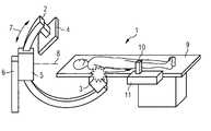
- FIG. 1a perspective view an x-ray system which is used in angiography or cardiography;
- FIG. 2the x-ray system from FIG. 1 in a state in which there is a danger of a collision with the patient bed;
- FIG. 3a block diagram of a circuit for controlling the x-ray system from FIGS. 1 and 2 .
- FIG. 4shows a side view of an embodiment implementing a magnetic navigation system.
- the x-ray system 1comprises a C-shaped x-ray arm 2 , on the ends of which an x-ray source 3 and an x-ray detector 4 are mounted.
- the x-ray arm 2is held by a support 5 which is mounted on a stand 6
- the x-ray arm 2can be moved in the support 5 in a circular direction 7 .
- the support 5is mounted on the stand 6 so that it can pivot around an axis 8 .
- the stand 6can also be moved around the floor.
- the x-ray arm 2is both moved in the circular direction 7 and also rotated around the pivot axis 8 .
- the x-ray arm 2executes a relative movement in relation to a patient bed 9 .
- the x-ray arm 2is controlled amongst other methods with the aid of a joystick 10 of a guidance device 11 .
- the x-ray arm 2will always move in the circular direction 7 if the joystick 10 is pushed to the left or to the right.
- the x-ray arm 2performs a rotational movement if the joystick 10 is pushed forwards or backwards.
- the x-ray system 1is used for the treatment of a patient 12 lying on the patient bed 9 , the personnel are frequently busy operating on the patient 12 . Thus their full attention is as a rule not available for the control of the x-ray arm 2 . Thus, as shown in FIG. 2 , there is always the danger of the collision 13 between the x-ray arm 2 and the components mounted thereon and the patient bed 9 . In addition there can also be collisions between the x-ray arm 2 and the components mounted thereon and further obstacles, such as further functional units arranged in the area of the patient bed 9 . These types of functional units can for example be magnets for magnetic navigation of a catheter equipped with a magnetic tip in the body of the patient 12 .
- the x-ray system 1warns the user who is manually operating the joystick 10 , not by using an additional acoustic or optical signal, but by tactile means.
- FIG. 3shows a block diagram of the x-ray system 1 .
- a position sensor 14monitors the movement of the x-ray arm 2 .
- the position sensor 14applies a position signal 16 to the monitoring device 15 . If the monitoring device 15 establishes the threat of a collision 13 , a setting device 16 is used to output an activation signal 17 .
- the setting device 16exerts a force effect 18 on the joystick 10 of the guidance device 11 .
- the force effect 18can result in or can cause an oscillation or vibration of the joystick 10 so that the force exerted by the user on the joystick 10 is inhibited.
- the latterhas the advantage that the user, as a result of the inhibition of the movement of the joystick 10 , cannot move the joystick 10 in a direction which would lead to a collision 13 between the x-ray arm 2 and an obstacle.
- the guidance device 11not only applies a control signal 19 to the setting devices for the x-ray arm, but will preferably also forward the control signal 19 to the monitoring device 15 so that the monitoring device can check whether the desired movement of the x-ray arm through activation of the joystick 10 leads to a collision.
- the intensity of the force effect 18advantageously depends on the level of the danger of a collision.
- the force effect 18increases as the danger of a collision 13 increases.
- FIG. 4shows an alternative embodiment, similar to embodiment in FIG. 1 .
- the support arm 20has mounted thereon a magnet 22 in place of an x-ray source.
- joystick 10instead of the joystick 10 , modified control elements can also be used.
- a joystick 10can be replaced by a tracker ball let into a recess, of which the movement is detected by sensors.
- a computer mousecan also basically be considered for controlling the x-ray arm 2 .
- pedalscan also be used for control of the x-ray arm.
- the feedback messageis communicated to the user directly on activation of the joystick 10 and since the force effect 18 depends on the probability of the collision 13 , the user can move the x-ray arm 2 almost without risk. It is further of advantage that the attention of the medical personnel and the peace and quiet of the patient are not adversely affected by distracting acoustic signals.
- the concept described herecan also be used in conjunction with x-ray devices which feature a number of x-ray arms 2 .
- the moveable components for which collisions with an obstacle are to be avoided where possiblecan in addition also be components which record images in other wavelength ranges.
- Furthermore considerationcan be given to controlling the magnets of a magnetic navigation device for controlling a magnetic tip of a catheter in the body of a patient in accordance with the concept described here.
Landscapes
- Health & Medical Sciences (AREA)
- Life Sciences & Earth Sciences (AREA)
- Medical Informatics (AREA)
- Engineering & Computer Science (AREA)
- Radiology & Medical Imaging (AREA)
- Biomedical Technology (AREA)
- Biophysics (AREA)
- Nuclear Medicine, Radiotherapy & Molecular Imaging (AREA)
- Optics & Photonics (AREA)
- Pathology (AREA)
- Physics & Mathematics (AREA)
- High Energy & Nuclear Physics (AREA)
- Heart & Thoracic Surgery (AREA)
- Molecular Biology (AREA)
- Surgery (AREA)
- Animal Behavior & Ethology (AREA)
- General Health & Medical Sciences (AREA)
- Public Health (AREA)
- Veterinary Medicine (AREA)
- Apparatus For Radiation Diagnosis (AREA)
Abstract
Description
- a medical functional unit which can be controlled by a user and is moveable in relation to a patient bed,
- a position sensor, which detects the position of the functional unit, and with
- a monitoring device connected downstream from the position sensor which monitors the movement of the functional unit and, if there is a danger of a collision with an obstacle, generates a warning signal perceptible to the user.
Claims (11)
Applications Claiming Priority (2)
| Application Number | Priority Date | Filing Date | Title |
|---|---|---|---|
| DE102005028215.6 | 2005-06-17 | ||
| DE102005028215ADE102005028215A1 (en) | 2005-06-17 | 2005-06-17 | X-ray system used for treatment of patient, has guidance device that includes user-operated joystick which exerts vibratory warning force, that can be perceived in tactile manner by user, based on warning signal from monitoring device |
Publications (2)
| Publication Number | Publication Date |
|---|---|
| US20060285644A1 US20060285644A1 (en) | 2006-12-21 |
| US7302040B2true US7302040B2 (en) | 2007-11-27 |
Family
ID=37513412
Family Applications (1)
| Application Number | Title | Priority Date | Filing Date |
|---|---|---|---|
| US11/455,262ActiveUS7302040B2 (en) | 2005-06-17 | 2006-06-16 | Device for medical provision |
Country Status (2)
| Country | Link |
|---|---|
| US (1) | US7302040B2 (en) |
| DE (1) | DE102005028215A1 (en) |
Cited By (6)
| Publication number | Priority date | Publication date | Assignee | Title |
|---|---|---|---|---|
| US20080279333A1 (en)* | 2007-05-09 | 2008-11-13 | Siemens Aktiengesellschaft | Angiography device and associated recording method with a mechanism for collision avoidance |
| US20110224904A1 (en)* | 2010-03-10 | 2011-09-15 | Wendelin Feiten | Method for monitoring the spatial environment of a mobile device |
| US20120136480A1 (en)* | 2010-11-30 | 2012-05-31 | Samsung Electronics, Co., Ltd | Method to control medical equipment |
| CN102836506A (en)* | 2011-06-20 | 2012-12-26 | 重庆微海软件开发有限公司 | Safety collision avoidance system and method of ultrasonic treatment equipment |
| US20160193731A1 (en)* | 2015-01-02 | 2016-07-07 | Stefan Sattler | Robotic medical apparatus with collision detection and method for collision detection in a robotic medical apparatus |
| KR101720032B1 (en)* | 2016-03-14 | 2017-03-27 | 재단법인대구경북과학기술원 | Magnetic steering system and vision system combined bed for surgery |
Families Citing this family (8)
| Publication number | Priority date | Publication date | Assignee | Title |
|---|---|---|---|---|
| DE102007002401A1 (en)* | 2007-01-17 | 2008-07-31 | Siemens Ag | Medical examination or intervention facility |
| DE102007018810A1 (en)* | 2007-04-20 | 2008-10-30 | Siemens Ag | Method for motion monitoring in a medical device and associated medical device |
| DE102007032540B4 (en)* | 2007-07-12 | 2015-05-21 | Siemens Aktiengesellschaft | Method for controlling the movement of a moving part of an X-ray image recording system and X-ray image recording system coupled to video cameras |
| DE102007044365A1 (en)* | 2007-09-17 | 2009-03-26 | Siemens Ag | Manual operating device for two-dimensional position control of mechanical or virtual movement of components of medical diagnostic and therapy system, comprises basic module, which has generator system and switch element |
| DE102011083876B4 (en) | 2011-09-30 | 2018-12-27 | Siemens Healthcare Gmbh | Method for controlling the movement of an X-ray device and X-ray system |
| JP6469336B2 (en)* | 2013-02-12 | 2019-02-13 | キヤノンメディカルシステムズ株式会社 | X-ray diagnostic apparatus and control method of X-ray diagnostic apparatus |
| WO2015087103A1 (en) | 2013-12-12 | 2015-06-18 | General Electric Company | Mobile medical imaging robot |
| US11207035B2 (en)* | 2019-04-10 | 2021-12-28 | Siemens Healthcare Gmbh | Sensor-based patient treatment support |
Citations (8)
| Publication number | Priority date | Publication date | Assignee | Title |
|---|---|---|---|---|
| DE3604955C2 (en) | 1986-02-17 | 1994-03-24 | Siemens Ag | X-ray diagnostic device |
| US5821920A (en) | 1994-07-14 | 1998-10-13 | Immersion Human Interface Corporation | Control input device for interfacing an elongated flexible object with a computer system |
| US5878112A (en)* | 1996-06-25 | 1999-03-02 | Siemens Aktiengesellschaft | Medical system having movable components and a control device for preventing component collisions |
| DE19912169A1 (en) | 1998-12-29 | 2000-07-06 | Bosch Gmbh Robert | Steer-by-wire steering system for vehicles has electronic steering regulator connected to steering control devices that modifies driver's steering demand depending on dynamic parameters |
| US6219604B1 (en) | 1998-12-29 | 2001-04-17 | Robert Bosch Gmbh | Steer-by-wire steering system for motorized vehicles |
| US20010016517A1 (en)* | 1997-07-17 | 2001-08-23 | Satoshi Nishiumi | Video game system |
| US6723106B1 (en) | 1998-11-23 | 2004-04-20 | Microdexterity Systems, Inc. | Surgical manipulator |
| DE69532536T2 (en) | 1994-11-23 | 2004-12-23 | Immersion Corp., San Jose | DEVICE WITH MECHANICAL INPUT / OUTPUT FOR COMPUTER SYSTEMS WITH AN INTERFACE FOR FLEXIBLE LONG STRETCHED ITEMS |
- 2005
- 2005-06-17DEDE102005028215Apatent/DE102005028215A1/ennot_activeWithdrawn
- 2006
- 2006-06-16USUS11/455,262patent/US7302040B2/enactiveActive
Patent Citations (9)
| Publication number | Priority date | Publication date | Assignee | Title |
|---|---|---|---|---|
| DE3604955C2 (en) | 1986-02-17 | 1994-03-24 | Siemens Ag | X-ray diagnostic device |
| US5821920A (en) | 1994-07-14 | 1998-10-13 | Immersion Human Interface Corporation | Control input device for interfacing an elongated flexible object with a computer system |
| DE69532536T2 (en) | 1994-11-23 | 2004-12-23 | Immersion Corp., San Jose | DEVICE WITH MECHANICAL INPUT / OUTPUT FOR COMPUTER SYSTEMS WITH AN INTERFACE FOR FLEXIBLE LONG STRETCHED ITEMS |
| US5878112A (en)* | 1996-06-25 | 1999-03-02 | Siemens Aktiengesellschaft | Medical system having movable components and a control device for preventing component collisions |
| US20010016517A1 (en)* | 1997-07-17 | 2001-08-23 | Satoshi Nishiumi | Video game system |
| US6723106B1 (en) | 1998-11-23 | 2004-04-20 | Microdexterity Systems, Inc. | Surgical manipulator |
| DE69918569T2 (en) | 1998-11-23 | 2005-03-24 | Microdexterity Systems Inc., Memphis | SURGICAL MANIPULATOR |
| DE19912169A1 (en) | 1998-12-29 | 2000-07-06 | Bosch Gmbh Robert | Steer-by-wire steering system for vehicles has electronic steering regulator connected to steering control devices that modifies driver's steering demand depending on dynamic parameters |
| US6219604B1 (en) | 1998-12-29 | 2001-04-17 | Robert Bosch Gmbh | Steer-by-wire steering system for motorized vehicles |
Cited By (10)
| Publication number | Priority date | Publication date | Assignee | Title |
|---|---|---|---|---|
| US20080279333A1 (en)* | 2007-05-09 | 2008-11-13 | Siemens Aktiengesellschaft | Angiography device and associated recording method with a mechanism for collision avoidance |
| US7564949B2 (en)* | 2007-05-09 | 2009-07-21 | Siemens Aktiengesellschaft | Angiography device and associated recording method with a mechanism for collision avoidance |
| US20110224904A1 (en)* | 2010-03-10 | 2011-09-15 | Wendelin Feiten | Method for monitoring the spatial environment of a mobile device |
| US20120136480A1 (en)* | 2010-11-30 | 2012-05-31 | Samsung Electronics, Co., Ltd | Method to control medical equipment |
| US9298194B2 (en)* | 2010-11-30 | 2016-03-29 | Samsung Electronics Co., Ltd. | Method to control medical equipment |
| CN102836506A (en)* | 2011-06-20 | 2012-12-26 | 重庆微海软件开发有限公司 | Safety collision avoidance system and method of ultrasonic treatment equipment |
| CN102836506B (en)* | 2011-06-20 | 2015-07-08 | 重庆微海软件开发有限公司 | Safety collision avoidance system and method of ultrasonic treatment equipment |
| US20160193731A1 (en)* | 2015-01-02 | 2016-07-07 | Stefan Sattler | Robotic medical apparatus with collision detection and method for collision detection in a robotic medical apparatus |
| US9943962B2 (en)* | 2015-01-02 | 2018-04-17 | Siemens Aktiengesellschaft | Robotic medical apparatus with collision detection and method for collision detection in a robotic medical apparatus |
| KR101720032B1 (en)* | 2016-03-14 | 2017-03-27 | 재단법인대구경북과학기술원 | Magnetic steering system and vision system combined bed for surgery |
Also Published As
| Publication number | Publication date |
|---|---|
| US20060285644A1 (en) | 2006-12-21 |
| DE102005028215A1 (en) | 2006-12-28 |
Similar Documents
| Publication | Publication Date | Title |
|---|---|---|
| US7302040B2 (en) | Device for medical provision | |
| US8041411B2 (en) | Device and method for controlling a magnetic element in the body of a patient | |
| US11013561B2 (en) | Medical device navigation system | |
| JP7608165B2 (en) | Foot-controlled cursor | |
| US7618189B2 (en) | Bed apparatus, X-ray diagnostic apparatus, and method of controlling a bed for X-ray diagnostic apparatus | |
| CN107735031B (en) | Object approach detection for medical diagnostic apparatus | |
| CN112118799A (en) | Virtual foot pedal | |
| JP2016531685A (en) | Method and apparatus for navigating active surgical instruments | |
| CN109330688B (en) | Safety self-checking endoscopic auxiliary manipulator and its intelligent control system | |
| CN104394768B (en) | Versatile Interfaces for Medical Imaging | |
| JPH08266536A (en) | Medical x-ray system | |
| JP2018075132A (en) | X-ray diagnostic apparatus | |
| JP7526639B2 (en) | Operation device and X-ray diagnostic system | |
| JP2008237684A (en) | X-ray imaging apparatus and control method thereof | |
| JP2009072360A (en) | X-ray diagnostic apparatus | |
| US20050117710A1 (en) | Motorized adjustable x-ray apparatus | |
| EP0923275B1 (en) | X-ray handswitch with integral indicator means | |
| JP3688382B2 (en) | X-ray diagnostic equipment | |
| CN114848140A (en) | Operation table, seat, control method of seat and operation table system | |
| CN109316198B (en) | Interaction of operating parameters in a medical system | |
| JP5326103B2 (en) | System and method for X-ray system status display | |
| US6424855B1 (en) | Medical diagnostic imaging apparatus | |
| JP3575848B2 (en) | Control device for diagnostic imaging device | |
| EP1501416A1 (en) | Medical examination device having patient positioning means movable under safety control | |
| US20240188907A1 (en) | X-ray diagnostic device and medical couch device |
Legal Events
| Date | Code | Title | Description |
|---|---|---|---|
| AS | Assignment | Owner name:SIEMENS AKTIENGESELLSCHAFT, GERMANY Free format text:ASSIGNMENT OF ASSIGNORS INTEREST;ASSIGNOR:CAMUS, ESTELLE;REEL/FRAME:017990/0469 Effective date:20060509 | |
| STCF | Information on status: patent grant | Free format text:PATENTED CASE | |
| FPAY | Fee payment | Year of fee payment:4 | |
| FPAY | Fee payment | Year of fee payment:8 | |
| AS | Assignment | Owner name:SIEMENS HEALTHCARE GMBH, GERMANY Free format text:ASSIGNMENT OF ASSIGNORS INTEREST;ASSIGNOR:SIEMENS AKTIENGESELLSCHAFT;REEL/FRAME:039271/0561 Effective date:20160610 | |
| MAFP | Maintenance fee payment | Free format text:PAYMENT OF MAINTENANCE FEE, 12TH YEAR, LARGE ENTITY (ORIGINAL EVENT CODE: M1553); ENTITY STATUS OF PATENT OWNER: LARGE ENTITY Year of fee payment:12 | |
| AS | Assignment | Owner name:SIEMENS HEALTHINEERS AG, GERMANY Free format text:ASSIGNMENT OF ASSIGNORS INTEREST;ASSIGNOR:SIEMENS HEALTHCARE GMBH;REEL/FRAME:066088/0256 Effective date:20231219 | |
| AS | Assignment | Owner name:SIEMENS HEALTHINEERS AG, GERMANY Free format text:CORRECTIVE ASSIGNMENT TO CORRECT THE ASSIGNEE PREVIOUSLY RECORDED AT REEL: 066088 FRAME: 0256. ASSIGNOR(S) HEREBY CONFIRMS THE ASSIGNMENT;ASSIGNOR:SIEMENS HEALTHCARE GMBH;REEL/FRAME:071178/0246 Effective date:20231219 |