US7302015B2 - Motion estimation method for moving picture compression coding - Google Patents
Motion estimation method for moving picture compression codingDownload PDFInfo
- Publication number
- US7302015B2 US7302015B2US10/428,629US42862903AUS7302015B2US 7302015 B2US7302015 B2US 7302015B2US 42862903 AUS42862903 AUS 42862903AUS 7302015 B2US7302015 B2US 7302015B2
- Authority
- US
- United States
- Prior art keywords
- motion point
- motion
- point
- difference
- new
- Prior art date
- Legal status (The legal status is an assumption and is not a legal conclusion. Google has not performed a legal analysis and makes no representation as to the accuracy of the status listed.)
- Expired - Fee Related, expires
Links
Images


Classifications
- H—ELECTRICITY
- H04—ELECTRIC COMMUNICATION TECHNIQUE
- H04N—PICTORIAL COMMUNICATION, e.g. TELEVISION
- H04N19/00—Methods or arrangements for coding, decoding, compressing or decompressing digital video signals
- H04N19/50—Methods or arrangements for coding, decoding, compressing or decompressing digital video signals using predictive coding
- H04N19/503—Methods or arrangements for coding, decoding, compressing or decompressing digital video signals using predictive coding involving temporal prediction
- H04N19/51—Motion estimation or motion compensation
- H04N19/557—Motion estimation characterised by stopping computation or iteration based on certain criteria, e.g. error magnitude being too large or early exit
- H—ELECTRICITY
- H04—ELECTRIC COMMUNICATION TECHNIQUE
- H04N—PICTORIAL COMMUNICATION, e.g. TELEVISION
- H04N19/00—Methods or arrangements for coding, decoding, compressing or decompressing digital video signals
- H04N19/50—Methods or arrangements for coding, decoding, compressing or decompressing digital video signals using predictive coding
- H04N19/503—Methods or arrangements for coding, decoding, compressing or decompressing digital video signals using predictive coding involving temporal prediction
- H04N19/51—Motion estimation or motion compensation
- H—ELECTRICITY
- H04—ELECTRIC COMMUNICATION TECHNIQUE
- H04N—PICTORIAL COMMUNICATION, e.g. TELEVISION
- H04N5/00—Details of television systems
- H04N5/14—Picture signal circuitry for video frequency region
- H04N5/144—Movement detection
- H04N5/145—Movement estimation
Definitions
- the present inventionrelates to a moving picture compression coding method, and more particularly to a motion estimation method for image compression coding, and a computer-readable recording medium on which a program for implementing the motion estimation method is recorded.
- a mobile phone servicehas been limited to only a voice service in the second generation wireless network because the second generation wireless network has a narrow bandwidth, therefore the third generation wireless network such as IMT (International Mobile Telecommunication)-2000 service was recently developed to provide users with a moving image service as well as the voice service.
- IMTInternational Mobile Telecommunication
- the size of image datais much larger than that of voice or character data. Consequently, the total size of such image data must be compressed down to a prescribed level. Provided that the size of image data is not compressed down to the prescribed level, it is impossible to process the image data in real time.
- image compression international standards for image compressionfor example, JPEG (Joint Photograph Expert Group) serving as a still image standard, MPEG (Moving Picture Experts Group)1 for TV broadcasting as one of moving picture standards, MPEG2 for satellite broadcasting as one of moving picture standards, and MPEG4 for low bit rate transmission as one of moving picture standards.
- JPEGJoint Photograph Expert Group
- MPEGMotion Picture Experts Group
- the MPEG4is an international standard for compression coding of digital image and audio data having a transfer rate of below 64 kbps, and therefore is a compression-coding standard for image or video data having an ultralow transfer rate and a high compression rate as compared to the MPEG1 or MPEG2, and is mainly applied to mobile telecommunications.
- image data compressionis established by removing redundant data caused by similarities between data of image information and data representing the image information.
- the spatial redundancyis based on similarities between values of adjacent pixels within a frame image, indicates that an arbitrary pixel has a value similar to that of its adjacent pixel, and is controlled by a DCT (Discrete Cosine Transform).
- DCTDiscrete Cosine Transform
- the stochastic redundancyis based on similarities between symbols within a frame image, indicates that a plurality of data are stochastically and unevenly distributed on the frame image such that an arbitrary symbol has a value similar to that of its adjacent pixel, and is controlled by a VLC (Variable Length Coding) serving as an entropy coding method.
- the VLCindicates a method for allocating a bit having a prescribed size proportional to a symbol size.
- the temporal redundancyis based on similarities between a current frame image and a previous frame image, and is controlled by a ME/MC (Motion Estimation/Motion Compensation).
- the MEis adapted to detect a motion vector between a current frame image and a previous frame image, generates a new frame image by a ME operation using the detected motion vector, subtracts the new frame image from the current frame image to remove the same data between the current frame image and the new frame image in such a way that the temporal redundancy is controlled.
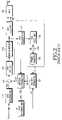
- FIG. 1is a view illustrating a block diagram of a conventional system for transmitting/receiving image data.
- the conventional system for transmitting/receiving image dataincludes an image data transmitter 100 for compressing image data, and transmitting a compression image signal of the image data; a satellite 1 for receiving the image signal from the image data transmitter 100 , and transmitting it to a receiver; and an image data receiver 200 for receiving the image signal from satellite 1 , decompressing the image signal, and restoring the original image data.
- the image data transmitter 100includes a MPEG source decoder 110 for compressing video data (VD) and audio data (AD), a text encoder 130 for compressing text data (TD), a channel encoder 150 for performing a channel encoding operation on encoded data of the MPEG source encoder 110 and the text encoder 130 to remove a noise from the encoded data, and a RF (Radio Frequency) unit 170 for modulating encoded data of the channel encoder 150 , and transmitting it over a first antenna ANT 1 . In this manner, the signal transmitted from the transmitter 100 is relayed to the receiver 200 over the satellite 1 .
- the image data receiver 200includes a baseband processor 210 for demodulating an image signal received from satellite 1 over a second antenna ANT 2 , thereby restoring the image signal to baseband image data, a channel decoder 220 for detecting errors of the image data received from the baseband processor 210 , correcting the errors, and performing image restoration, and a MPEG decoder 230 for decompressing compressed image data received from the channel decoder 220 , and restoring original image data.
- the TDis also decoded since the TD is also an input to channel encoder.
- FIG. 2is a view illustrating a detailed block diagram of a MPEG source encoder 110 contained in the image data transmitter 100 shown in FIG. 1 .
- the MPEG source encoder 110includes a 8 ⁇ 8 blocking unit 111 for dividing one frame image Vin into 8 ⁇ 8 blocks, a subtracter 112 for subtracting a generated frame image from a current frame image received from the 8 ⁇ 8 blocking unit 111 , a 8 ⁇ 8 DCT (discrete cosine transformation) unit 113 for performing a DCT operation on the current frame image received from the subtracter 112 , a 8 ⁇ 8 quantizer 114 for quantizing a frame image received from the 8 ⁇ 8 DCT unit 113 , a VLC unit 115 for performing a VLC operation on a current frame image received from the 8 ⁇ 8 quantizer 114 , a 8 ⁇ 8 dequantizer 117 for dequantizing a frame image received from the 8 ⁇ 8 quantizer 114 , a 8 ⁇ 8 IDCT (Inverse Discrete Cosine Transform
- One frame imagehas a variety of resolutions such as 720 ⁇ 480 and 1192 ⁇ 1080, etc.
- the motion estimator 121 for estimating a motion vector between a current frame image and a previous frame imageconsiders each such frame image of 16 ⁇ 16 pixel blocks, and processes the frame image in block units.
- the motion estimator 121compares a pixel value of a current frame image F(t) with that of a previous frame image F(t ⁇ 1) to estimate a moving direction of an image, i.e., a motion vector, and will hereinafter be described in more detail.
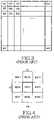
- FIG. 3is a view illustrating an exemplary blocked frame image.
- the 16 ⁇ 16 blocking unit 123 shown in FIG. 2divides one frame image into 16 ⁇ 16 blocks according to the MPEG4 standard.
- An example of such 16 ⁇ 16 blocked frame imageis shown in FIG. 3 .
- an overall frame imageis divided into 16 ⁇ 16 blocks, and the overall frame image is denoted by a group of the 16 ⁇ 16 blocks such as B 11 , B 12 . . . B 1 m , B 21 , B 22 . . . Bn 1 . . . Bnm.
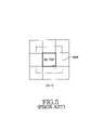
- FIG. 4is a view illustrating a current frame image formed by partially-blocking the frame image of FIG. 3 , and depicts a current frame image F(t) composed of 9 partial blocks wherein 8 partial blocks are arranged to surround an exemplary block that corresponds from the previous frame to the current frame.
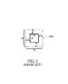
- FIG. 5is a view illustrating a previous frame image having block B(t ⁇ 1) 22 corresponding to block B(t) 22 of the current frame image of FIG. 4 .
- FIG. 5depicts a previous frame image F(t ⁇ 1) composed of 9 partial blocks wherein 8 partial blocks are arranged to surround an arbitrary block B(t ⁇ 1) 22 corresponding to the current block B(t) 22 shown in FIG. 4 .
- the search window SRWis determined depending on a movable range between successive two frame images comprising about 24 frames per second.
- a corresponding block B(t ⁇ 1) 22 of the SRWis extended in the range of ⁇ block size/2.
- the motion estimator 121 shown in FIG. 2compares the current block B(t) 22 of FIG. 4 with each block comprising the SRW of FIG. 5 .
- the motion estimator 121establishes such a comparison process in the direction from the upper left end as shown in FIG. 6 a to the lower right end.
- the comparison process of the motion estimator 121is established along the same direction as an electron gun scanning direction of a cathode ray tube as shown in FIG. 6 b .
- the motion estimator 121finds the most similar matching block to the current block in order to estimate a motion vector. This algorithm for finding the most similar matching block is called a block matching algorithm.
- each pixel value within a blockis adapted as a comparison value among blocks, and in more detail, a pixel value of a current block of a current frame image is compared to that of a corresponding block of a previous frame image.
- the block matching algorithmsubtracts a pixel value of a corresponding block from that of a current block, finds an arbitrary block having the least error (or the least difference), calculates a position vector of a matching block on the basis of the, current block, and thereby estimates a motion vector.
- the motion vectoris generally estimated in light of two factors composed of image quality degradation prevention and high speed estimation.
- a full search algorithmThere are a variety of block matching algorithms, and particularly, one of them is called a full search algorithm.
- This full search algorithmis adapted as an estimation reference of other algorithms because its resultant estimated image has the best image quality.
- the full search algorithmneeds 24 bits in total to display a color pixel because 8 bits are assigned to each of 3 primary colors (i.e., R, G, and B).
- R, G, and B3 primary colors
- a representative one of the method for reducing the number of search points using the UESAis a TSS (Three Step Search) method that will hereinafter be described in more detail.
- FIG. 7is an exemplary view illustrating a SRW (shown in FIG. 5 ) of a predetermined size.
- the SRWis extended in all directions of a reference block having 16 ⁇ 16 pixels such that a large-sized search window larger than the reference block is formed.
- the SRWis typically extended by a size of (+block size/2) in one direction of the reference block, but FIG. 7 indicates this size of (+block size/2) as a prescribed value of +7 for the convenience of description.
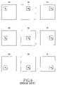
- FIGS. 8 a ⁇ 8 iare exemplary views illustrating search points within a SRW determined by the conventional TSS method.
- the TSS methoddoes not determine whether a current block is matched with all blocks of the SRW, but determines whether the current block is matched with one or more of 9 blocks among all blocks as shown in FIGS. 8 a ⁇ 8 i .
- center points of these 9 blocks to be searched within the SRWare indicated as reference numerals 1 ⁇ 9 as shown in FIGS. 8 a ⁇ 8 i.
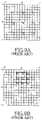
- FIGS. 9 a ⁇ 9 care exemplary views illustrating search points adapted for explaining the conventional TSS method.
- search pointswhich may each be a center point of a block in case of using the full search method within a SRW are indicated by small circles, and 9 search points determined by the TSS method are assigned with reference numerals 1 ⁇ 9 , respectively.
- a SADSud of Absolute Difference
- the SADis defined as the sum of absolute differences (or errors) between a pixel value of a current block of a current frame image F(t) and a pixel value of a block corresponding to the current block on a SRW of a previous frame image F(t ⁇ 1), and is represented as the following Eq. 1:
- I c (k+i,l+j)is a pixel value of a current frame image block
- I p (k+x+i,l+y+j)is a pixel value of a corresponding block on a SRW of a previous frame image
- ‘x’ and ‘y’are coordinates within the SRW
- ‘k’ and ‘l’are coordinates within a corresponding block
- ‘n’is a size of a matching block.
- the TSS methoddetermines a motion vector through first to third search processes using the UESA method for monotonically increasing an error value on each search point in proportion to a difference between the error value and a global motion vector.
- the first search processcalculates all SADs on the basis of nine search points 1 ⁇ 9 shown in FIG. 9 a .
- the second search processcalculates again all SADs on the basis of nine search points 21 ⁇ 29 of FIG. 9 b on the basis of a search point ‘2’ of FIG. 9 a when a search point of a minimum SAD calculated by the first search process is ‘2’ shown in FIG. 9 a .
- the third search processcalculates all SADs on the basis of nine search points on the basis of a search point ‘22’ of FIG. 9 b when a search point of a minimum SAD calculated by the second search process is ‘22’ shown in FIG. 9 b , and thereby one search point having a minimum SAD is determined as a motion vector.
- the aforesaid TSS methodsearches all the 9 search points in each of the first to third search processes.
- all the 9 search pointsare searched in the first search process
- 8 search points other than one search point calculated by the first search processare searched in the second search process
- 8 search points other than one search point calculated by the second search processare searched in the third search process. Therefore, the TSS method searches 25 search points in total.
- the TSS methodhas an excessively long search time such that it is impossible to perform real-time processing of images using software.
- the present inventionhas been made in view of the above problems, and it is an object of the present invention to provide a moving picture compression coding method, and more particularly to a method for finding a motion vector at a high speed without degrading a compression rate and an image quality, and to a computer-readable recording medium on which a program for implementing the motion vector finding method is recorded.
- a motion estimation method for a motion picture compression coding in a MPEG4-based motion estimation methodcomprising the steps of: a) estimating an initial motion point; b) performing a Newton-Raphson method using a MAD (Mean Absolute Difference) of the estimated motion point of the step (a) as an objective function, and finding a new motion point; c) determining whether a difference between the new motion point of the step (b) and the estimated motion point is less than a minimum error range, estimating the new motion point as the initial motion point when the difference is more than the minimum error range, and performing the step (b); and d) determining whether a difference between the new motion point of the step (b) and the estimated motion point is less than a minimum error range, estimating the new motion point as a final motion point when the difference is less than the minimum error range, and determining a motion vector.
- MADMel Absolute Difference
- a computer-readable recording mediumon which a program is recorded in a motion estimation system having a processor therein, the program comprising the steps of: a) estimating an initial motion point; b) performing a Newton-Raphson method using a MAD (Mean Absolute Difference) of the estimated motion point of the step (a) as an objective function, and finding a new motion point; c) determining whether a difference between the new motion point of the step (b) and the estimated motion point is less than a minimum error range, estimating the new motion point as the initial motion point when the difference is more than the minimum error range, and performing the step (b); and d) determining whether a difference between the new motion point of the step (b) and the estimated motion point is less than a minimum error range, estimating the new motion point as a final motion point when the difference is less than the minimum error range, and determining a motion vector.
- MADMel Absolute Difference
- the present inventionuses the Newton-Raphson method being one of optimization methods for finding a minimum value, obtains a minimum MAD by repeatedly calculating a MAD of image blocks corresponding to each frame using a second-derivative method, and calculates a motion vector in case of the minimum MAD.
- the present inventionsuccessively minimizes a MAD value being an objective function used for the Newton-Raphson method, and thereby finds a motion vector at a high speed.
- FIG. 1is a view illustrating a block diagram of a conventional system for transmitting/receiving image data
- FIG. 2is a view illustrating a detailed block diagram of a MPEG source encoder contained in the image data transmitter shown in FIG. 1 ;
- FIG. 3is a view illustrating an exemplary blocked frame image
- FIG. 4is a view illustrating a current frame image formed by partially-blocking the frame image of FIG. 3 ;
- FIG. 5is a view illustrating a previous frame image having a block corresponding to the current frame image of FIG. 4 ;
- FIGS. 6 a ⁇ 6 bare exemplary views illustrating a first search position of a current block on a search window (SRW) and a search direction of the current block within the SRW, respectively;
- SRWsearch window
- FIG. 7is an exemplary view illustrating a SRW of a predetermined size
- FIGS. 8 a ⁇ 8 iare exemplary views illustrating search points within a SRW determined by a conventional TSS method
- FIGS. 9 a ⁇ 9 care exemplary views illustrating search points adapted for explaining the conventional TSS method
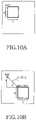
- FIGS. 10 a ⁇ 10 bare exemplary views illustrating a moving direction of a block in a motion vector detection method in accordance with the present invention
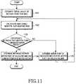
- FIG. 11is a flow chart illustrating a motion estimation method in accordance with the present invention.
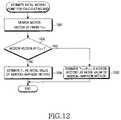
- FIG. 12is a flow chart illustrating a procedure for estimating an initial value of a motion point for calculating a MAD (Mean Absolute Difference) in accordance with the present invention.
- MADMel Absolute Difference
- a general curveis indicated as a function f(x), and a zero value (i.e., x-intercept) of the function f(x)is determined.
- the function f(x)is approximated by its own tangent line at an arbitrary position x0 corresponding to an initial estimate, and a new estimate is formed on the basis of a zero value x1 (i.e., x-intercept) of the tangent line. This simple process may be repeated the necessary number of times to achieve a desired precision.
- a zero value of a tangent line corresponding to the number (i) of repetitionsis represented as the following Eq. 2:
- the present inventionadapts a second-derivative operation of the above Newton-Raphson method.
- the Newton-Raphson method using the second-derivative operationis represented as the following Eq. 3:
- E( ⁇ )is a MAD (Mean Absolute Difference) serving as an objective function
- ⁇is a convergence factor
- ⁇is a predicted parameter value equal to an estimated position value of the present invention.
- the Newton-Raphson methodstops operating on condition that ⁇ (k+1) ⁇ (k) has a sufficiently low value.
- an initial estimated valueis determined at or close to the correct value and an optimal stop value should be also derived according to the Newton-Raphson method. Therefore, the present invention discloses a method for estimating such an initial value adapted to perform motion estimation as well as a stop condition adapted to the motion estimation.
- FIGS. 10 a ⁇ 10 billustrating a moving direction of a block in a motion vector detection method in accordance with the present invention.
- the present inventionuses a MAD instead of the conventional SAD adapted to perform motion detection. If the SAD is an overall error within a block, the MAD corresponds to a prescribed value formed by dividing the SAD by a block area with reference to a mean value of each pixel error within the block. That is, the MAD is adapted to the present invention for the convenience of description and better understanding of the present invention, but the SAD may be also adapted to the present invention if necessary.
- the MAD adapted to the present inventionperforms in accordance with the following Eq. 7:
- F n (a+i,b+j)is a pixel value of a current frame image block
- F n ⁇ 1 (a+x+i,b+y+j)is a pixel value of a corresponding block on a SRW of a previous frame image
- ‘x’ and ‘y’are coordinates within the SRW
- ‘a’ and ‘b’are coordinates within a corresponding block
- ‘L’is a block size.
- a point (a, b)is formed by moving a block by a point (x, y) from a point (a+x, b+y) of FIG. 10 b showing a previous frame.
- the point (x, y)is a motion vector mainly discussed later in the description.
- the present inventioncalculates an error for every pixel, and estimates a particular point on which a minimum one of the calculated errors is established. The minimum point is determined as a moving result point of a current point in such a way that such motion estimation is established by the present invention.
- FIG. 11is a flow chart illustrating a motion estimation method in accordance with the present invention.
- an initial value of a motion pointis estimated to calculate a MAD at step 1101 .
- the Newton-Raphson method adapted to the present inventionfluctuates in accuracy of a calculation result and the number of calculations according to the estimated initial value.
- a key point in the Newton-Raphson methodis a method for estimating such an initial value. Such a method for estimating the initial value will be described with reference to FIG. 12 .
- the MADis calculated in Eq. 7 on the basis of the estimated position, and a new MAD is calculated for a new point determined using the Newton-Raphson method shown in the Eq. 3 at step 1102 . It is determined at step 1103 whether a difference between the new motion point corresponding to the calculated MAD in Eq. 7 and the estimated motion point is more than a prescribed minimum error range.
- the minimum error rangeis preferably set to one pixel size according to a preferred embodiment of the present invention.
- a motion point corresponding to the calculated MADis then used as the initial or estimated value of the motion point for calculating a subsequent MAD at step 1105 , and a program returns to step 1102 such that a plurality of steps from the step 1102 are repeated.
- a calculation value of x of the motion pointis below one pixel adapted as a minimum error range proposed by the preferred embodiment of the present invention when the calculations of x and y are repeated in Eq. 3 to determine a new motion point, the next calculation of x in the Newton-Raphson Equation of Eq. 3 can be omitted, thereby effectively reducing the number of calculations.
- a difference between a motion point corresponding to the calculated MAD and a current positionis determined as a motion vector at step 1104 .
- FIG. 12is a flow chart illustrating a procedure for estimating an initial value of a motion point for calculating a MAD (Mean Absolute Difference) in accordance with the present invention.
- MADMel Absolute Difference
- a motion vector of a previous frame F n ⁇ 1is searched to estimate an initial value of a motion point for the MAD at step 1201 . If a motion vector of the previous frame F n ⁇ 1 exists at step 1202 , a parameter “current position (F n )+ motion vector of the previous frame (F n ⁇ 1 )” is estimated as an initial value of a motion point for calculating the MAD according to the Newton-Raphson method at step 1203 .
- the current position (F n )is estimated as an initial value of a motion point for calculating the MAD according to the Newton-Raphson method at step 1204 .
- the MPEG-4 image compression methodadapts the Newton-Raphson method using a second-derivative equation, and thereby finds a motion vector at a high speed without degrading a compression rate and an image quality.
- the present inventionuses a method for estimating an initial value according to the Newton-Raphson method, and thereby more quickly and correctly performs motion estimation.
- the aforementioned method according to the present inventionmay be implemented with a program, and may be recorded on a computer-readable recording medium such as a CD-ROM, a RAM, a floppy disc, a hard disc, and a magneto-optical disc, etc.
- a computer-readable recording mediumsuch as a CD-ROM, a RAM, a floppy disc, a hard disc, and a magneto-optical disc, etc.
Landscapes
- Engineering & Computer Science (AREA)
- Multimedia (AREA)
- Signal Processing (AREA)
- Computing Systems (AREA)
- Theoretical Computer Science (AREA)
- Compression Or Coding Systems Of Tv Signals (AREA)
Abstract
Description
where Ic(k+i,l+j) is a pixel value of a current frame image block, Ip(k+x+i,l+y+j)is a pixel value of a corresponding block on a SRW of a previous frame image, ‘x’ and ‘y’ are coordinates within the SRW, ‘k’ and ‘l’ are coordinates within a corresponding block, and ‘n’ is a size of a matching block.
where E(ξ) is a MAD (Mean Absolute Difference) serving as an objective function, ψ is a convergence factor, and ξ is a predicted parameter value equal to an estimated position value of the present invention.
ξ(1)is then calculated using ξ(0)shown in the following Eq. 6:
where Fn(a+i,b+j) is a pixel value of a current frame image block, Fn−1(a+x+i,b+y+j) is a pixel value of a corresponding block on a SRW of a previous frame image, ‘x’ and ‘y’ are coordinates within the SRW, ‘a’ and ‘b’ are coordinates within a corresponding block, and ‘L’ is a block size.
Claims (10)
Applications Claiming Priority (2)
| Application Number | Priority Date | Filing Date | Title |
|---|---|---|---|
| KRP2003-0000140 | 2003-01-02 | ||
| KR10-2003-0000140AKR100498951B1 (en) | 2003-01-02 | 2003-01-02 | Method of Motion Estimation for Video Coding in MPEG-4/H.263 Standards |
Publications (2)
| Publication Number | Publication Date |
|---|---|
| US20040131120A1 US20040131120A1 (en) | 2004-07-08 |
| US7302015B2true US7302015B2 (en) | 2007-11-27 |
Family
ID=32677834
Family Applications (1)
| Application Number | Title | Priority Date | Filing Date |
|---|---|---|---|
| US10/428,629Expired - Fee RelatedUS7302015B2 (en) | 2003-01-02 | 2003-05-02 | Motion estimation method for moving picture compression coding |
Country Status (2)
| Country | Link |
|---|---|
| US (1) | US7302015B2 (en) |
| KR (1) | KR100498951B1 (en) |
Cited By (40)
| Publication number | Priority date | Publication date | Assignee | Title |
|---|---|---|---|---|
| US20050093820A1 (en)* | 2003-10-20 | 2005-05-05 | Ruei-Shiang Suen | Wireless device having a distinct hardware video accelerator to support motion processing |
| US20060140451A1 (en)* | 2004-12-24 | 2006-06-29 | Lite-On Semiconductor Corp. | Motion detection method |
| US20070242752A1 (en)* | 2006-04-12 | 2007-10-18 | Sony Corporation | Motion-vector searching method and motion-vector searching apparatus |
| US20090115840A1 (en)* | 2007-11-02 | 2009-05-07 | Samsung Electronics Co. Ltd. | Mobile terminal and panoramic photographing method for the same |
| US8463037B2 (en) | 2011-03-31 | 2013-06-11 | Sony Corporation | Detection of low contrast for image processing |
| US20140301652A1 (en)* | 2013-04-08 | 2014-10-09 | Broadcom Corporation | Compression within a set of images |
| US10016220B2 (en) | 2011-11-01 | 2018-07-10 | Nuvasive Specialized Orthopedics, Inc. | Adjustable magnetic devices and methods of using same |
| US10039661B2 (en) | 2006-10-20 | 2018-08-07 | Nuvasive Specialized Orthopedics, Inc. | Adjustable implant and method of use |
| US10238427B2 (en) | 2015-02-19 | 2019-03-26 | Nuvasive Specialized Orthopedics, Inc. | Systems and methods for vertebral adjustment |
| US10271885B2 (en) | 2014-12-26 | 2019-04-30 | Nuvasive Specialized Orthopedics, Inc. | Systems and methods for distraction |
| US10349995B2 (en) | 2007-10-30 | 2019-07-16 | Nuvasive Specialized Orthopedics, Inc. | Skeletal manipulation method |
| US10405891B2 (en) | 2010-08-09 | 2019-09-10 | Nuvasive Specialized Orthopedics, Inc. | Maintenance feature in magnetic implant |
| US10517643B2 (en) | 2009-02-23 | 2019-12-31 | Nuvasive Specialized Orthopedics, Inc. | Non-invasive adjustable distraction system |
| US11207110B2 (en) | 2009-09-04 | 2021-12-28 | Nuvasive Specialized Orthopedics, Inc. | Bone growth device and method |
| US11246694B2 (en) | 2014-04-28 | 2022-02-15 | Nuvasive Specialized Orthopedics, Inc. | System for informational magnetic feedback in adjustable implants |
| USRE49061E1 (en) | 2012-10-18 | 2022-05-10 | Nuvasive Specialized Orthopedics, Inc. | Intramedullary implants for replacing lost bone |
| US11357547B2 (en) | 2014-10-23 | 2022-06-14 | Nuvasive Specialized Orthopedics Inc. | Remotely adjustable interactive bone reshaping implant |
| US11406432B2 (en) | 2011-02-14 | 2022-08-09 | Nuvasive Specialized Orthopedics, Inc. | System and method for altering rotational alignment of bone sections |
| US11445939B2 (en) | 2011-10-04 | 2022-09-20 | Nuvasive Specialized Orthopedics, Inc. | Devices and methods for non-invasive implant length sensing |
| US11497530B2 (en) | 2010-06-30 | 2022-11-15 | Nuvasive Specialized Orthopedics, Inc. | External adjustment device for distraction device |
| US11504162B2 (en) | 2015-12-10 | 2022-11-22 | Nuvasive Specialized Orthopedics, Inc. | External adjustment device for distraction device |
| US11576702B2 (en) | 2013-10-10 | 2023-02-14 | Nuvasive Specialized Orthopedics, Inc. | Adjustable spinal implant |
| US11577097B2 (en) | 2019-02-07 | 2023-02-14 | Nuvasive Specialized Orthopedics, Inc. | Ultrasonic communication in medical devices |
| US11589901B2 (en) | 2019-02-08 | 2023-02-28 | Nuvasive Specialized Orthopedics, Inc. | External adjustment device |
| US11596456B2 (en) | 2015-10-16 | 2023-03-07 | Nuvasive Specialized Orthopedics, Inc. | Adjustable devices for treating arthritis of the knee |
| US11602380B2 (en) | 2009-04-29 | 2023-03-14 | Nuvasive Specialized Orthopedics, Inc. | Interspinous process device and method |
| US11696836B2 (en) | 2013-08-09 | 2023-07-11 | Nuvasive, Inc. | Lordotic expandable interbody implant |
| US11712268B2 (en) | 2004-07-02 | 2023-08-01 | Nuvasive Specialized Orthopedics, Inc. | Expandable rod system to treat scoliosis and method of using the same |
| US11737787B1 (en) | 2021-05-27 | 2023-08-29 | Nuvasive, Inc. | Bone elongating devices and methods of use |
| US11766252B2 (en) | 2013-07-31 | 2023-09-26 | Nuvasive Specialized Orthopedics, Inc. | Noninvasively adjustable suture anchors |
| US11801187B2 (en) | 2016-02-10 | 2023-10-31 | Nuvasive Specialized Orthopedics, Inc. | Systems and methods for controlling multiple surgical variables |
| US11806054B2 (en) | 2021-02-23 | 2023-11-07 | Nuvasive Specialized Orthopedics, Inc. | Adjustable implant, system and methods |
| US11839410B2 (en) | 2012-06-15 | 2023-12-12 | Nuvasive Inc. | Magnetic implants with improved anatomical compatibility |
| US11857226B2 (en) | 2013-03-08 | 2024-01-02 | Nuvasive Specialized Orthopedics | Systems and methods for ultrasonic detection of device distraction |
| US11871971B2 (en) | 2012-10-29 | 2024-01-16 | Nuvasive Specialized Orthopedics, Inc. | Adjustable devices for treating arthritis of the knee |
| US11925389B2 (en) | 2008-10-13 | 2024-03-12 | Nuvasive Specialized Orthopedics, Inc. | Spinal distraction system |
| US11974782B2 (en) | 2008-11-10 | 2024-05-07 | Nuvasive Specialized Orthopedics, Inc. | External adjustment device for distraction device |
| US12023073B2 (en) | 2021-08-03 | 2024-07-02 | Nuvasive Specialized Orthopedics, Inc. | Adjustable implant |
| US12076241B2 (en) | 2008-03-25 | 2024-09-03 | Nuvasive Specialized Orthopedics, Inc. | Adjustable implant system |
| US12213708B2 (en) | 2020-09-08 | 2025-02-04 | Nuvasive Specialized Orthopedics, Inc. | Remote control module for adjustable implants |
Families Citing this family (8)
| Publication number | Priority date | Publication date | Assignee | Title |
|---|---|---|---|---|
| US20040248549A1 (en)* | 2003-06-04 | 2004-12-09 | Drews Paul C. | Entropy collection |
| KR100636785B1 (en)* | 2005-05-31 | 2006-10-20 | 삼성전자주식회사 | Multi-view stereoscopic imaging system and compression and decompression method applied to it |
| KR102070719B1 (en)* | 2013-01-23 | 2020-01-30 | 한국전자통신연구원 | Method for inter prediction and apparatus thereof |
| US10372528B1 (en) | 2014-12-15 | 2019-08-06 | Seagate Technology Llc | Random values from data errors |
| US10338890B1 (en) | 2015-01-07 | 2019-07-02 | Seagate Technology Llc | Random values from data errors |
| KR102173576B1 (en)* | 2020-01-21 | 2020-11-03 | 한국전자통신연구원 | Method for inter prediction and apparatus thereof |
| KR102281514B1 (en)* | 2020-01-21 | 2021-07-26 | 한국전자통신연구원 | Method for inter prediction and apparatus thereof |
| KR102380722B1 (en)* | 2020-10-28 | 2022-04-01 | 한국전자통신연구원 | Method for inter prediction and apparatus thereof |
Citations (3)
| Publication number | Priority date | Publication date | Assignee | Title |
|---|---|---|---|---|
| US20020034318A1 (en)* | 2000-07-28 | 2002-03-21 | Woo-Sung Sim | Motion Estimation method |
| US20020181745A1 (en)* | 2001-06-05 | 2002-12-05 | Hu Shane Ching-Feng | Multi-modal motion estimation for video sequences |
| US20040022419A1 (en)* | 1999-12-28 | 2004-02-05 | Martti Kesaniemi | Optical flow and image forming |
- 2003
- 2003-01-02KRKR10-2003-0000140Apatent/KR100498951B1/ennot_activeExpired - Fee Related
- 2003-05-02USUS10/428,629patent/US7302015B2/ennot_activeExpired - Fee Related
Patent Citations (3)
| Publication number | Priority date | Publication date | Assignee | Title |
|---|---|---|---|---|
| US20040022419A1 (en)* | 1999-12-28 | 2004-02-05 | Martti Kesaniemi | Optical flow and image forming |
| US20020034318A1 (en)* | 2000-07-28 | 2002-03-21 | Woo-Sung Sim | Motion Estimation method |
| US20020181745A1 (en)* | 2001-06-05 | 2002-12-05 | Hu Shane Ching-Feng | Multi-modal motion estimation for video sequences |
Cited By (64)
| Publication number | Priority date | Publication date | Assignee | Title |
|---|---|---|---|---|
| US20050094730A1 (en)* | 2003-10-20 | 2005-05-05 | Chang Li F. | Wireless device having a distinct hardware video accelerator to support video compression and decompression |
| US20050093820A1 (en)* | 2003-10-20 | 2005-05-05 | Ruei-Shiang Suen | Wireless device having a distinct hardware video accelerator to support motion processing |
| US11712268B2 (en) | 2004-07-02 | 2023-08-01 | Nuvasive Specialized Orthopedics, Inc. | Expandable rod system to treat scoliosis and method of using the same |
| US20060140451A1 (en)* | 2004-12-24 | 2006-06-29 | Lite-On Semiconductor Corp. | Motion detection method |
| US20070242752A1 (en)* | 2006-04-12 | 2007-10-18 | Sony Corporation | Motion-vector searching method and motion-vector searching apparatus |
| US8379725B2 (en)* | 2006-04-12 | 2013-02-19 | Sony Corporation | Motion-vector searching method and motion-vector searching apparatus |
| US10039661B2 (en) | 2006-10-20 | 2018-08-07 | Nuvasive Specialized Orthopedics, Inc. | Adjustable implant and method of use |
| US11172972B2 (en) | 2007-10-30 | 2021-11-16 | Nuvasive Specialized Orthopedics, Inc. | Skeletal manipulation method |
| US10349995B2 (en) | 2007-10-30 | 2019-07-16 | Nuvasive Specialized Orthopedics, Inc. | Skeletal manipulation method |
| US11871974B2 (en) | 2007-10-30 | 2024-01-16 | Nuvasive Specialized Orthopedics, Inc. | Skeletal manipulation method |
| US20090115840A1 (en)* | 2007-11-02 | 2009-05-07 | Samsung Electronics Co. Ltd. | Mobile terminal and panoramic photographing method for the same |
| US8411133B2 (en)* | 2007-11-02 | 2013-04-02 | Samsung Electronics Co., Ltd. | Mobile terminal and panoramic photographing method for the same |
| US12076241B2 (en) | 2008-03-25 | 2024-09-03 | Nuvasive Specialized Orthopedics, Inc. | Adjustable implant system |
| US11925389B2 (en) | 2008-10-13 | 2024-03-12 | Nuvasive Specialized Orthopedics, Inc. | Spinal distraction system |
| US11974782B2 (en) | 2008-11-10 | 2024-05-07 | Nuvasive Specialized Orthopedics, Inc. | External adjustment device for distraction device |
| US11918254B2 (en) | 2009-02-23 | 2024-03-05 | Nuvasive Specialized Orthopedics Inc. | Adjustable implant system |
| US10517643B2 (en) | 2009-02-23 | 2019-12-31 | Nuvasive Specialized Orthopedics, Inc. | Non-invasive adjustable distraction system |
| US11304729B2 (en) | 2009-02-23 | 2022-04-19 | Nuvasive Specialized Orthhopedics, Inc. | Non-invasive adjustable distraction system |
| US11602380B2 (en) | 2009-04-29 | 2023-03-14 | Nuvasive Specialized Orthopedics, Inc. | Interspinous process device and method |
| US11207110B2 (en) | 2009-09-04 | 2021-12-28 | Nuvasive Specialized Orthopedics, Inc. | Bone growth device and method |
| US11944358B2 (en) | 2009-09-04 | 2024-04-02 | Nuvasive Specialized Orthopedics, Inc. | Bone growth device and method |
| US11497530B2 (en) | 2010-06-30 | 2022-11-15 | Nuvasive Specialized Orthopedics, Inc. | External adjustment device for distraction device |
| US12178477B2 (en) | 2010-06-30 | 2024-12-31 | Globus Medical Inc. | External adjustment device for distraction system |
| US10405891B2 (en) | 2010-08-09 | 2019-09-10 | Nuvasive Specialized Orthopedics, Inc. | Maintenance feature in magnetic implant |
| US11406432B2 (en) | 2011-02-14 | 2022-08-09 | Nuvasive Specialized Orthopedics, Inc. | System and method for altering rotational alignment of bone sections |
| US12290290B2 (en) | 2011-02-14 | 2025-05-06 | Nuvasive, Inc. | System and method for altering rotational alignment of bone sections |
| US8463037B2 (en) | 2011-03-31 | 2013-06-11 | Sony Corporation | Detection of low contrast for image processing |
| US11445939B2 (en) | 2011-10-04 | 2022-09-20 | Nuvasive Specialized Orthopedics, Inc. | Devices and methods for non-invasive implant length sensing |
| US11918255B2 (en) | 2011-11-01 | 2024-03-05 | Nuvasive Specialized Orthopedics Inc. | Adjustable magnetic devices and methods of using same |
| US10016220B2 (en) | 2011-11-01 | 2018-07-10 | Nuvasive Specialized Orthopedics, Inc. | Adjustable magnetic devices and methods of using same |
| US11839410B2 (en) | 2012-06-15 | 2023-12-12 | Nuvasive Inc. | Magnetic implants with improved anatomical compatibility |
| USRE49720E1 (en) | 2012-10-18 | 2023-11-07 | Nuvasive Specialized Orthopedics, Inc. | Intramedullary implants for replacing lost bone |
| USRE49061E1 (en) | 2012-10-18 | 2022-05-10 | Nuvasive Specialized Orthopedics, Inc. | Intramedullary implants for replacing lost bone |
| US11871971B2 (en) | 2012-10-29 | 2024-01-16 | Nuvasive Specialized Orthopedics, Inc. | Adjustable devices for treating arthritis of the knee |
| US11857226B2 (en) | 2013-03-08 | 2024-01-02 | Nuvasive Specialized Orthopedics | Systems and methods for ultrasonic detection of device distraction |
| US9286696B2 (en)* | 2013-04-08 | 2016-03-15 | Broadcom Corporation | Compression within a set of images |
| US20140301652A1 (en)* | 2013-04-08 | 2014-10-09 | Broadcom Corporation | Compression within a set of images |
| US12329374B2 (en) | 2013-07-31 | 2025-06-17 | Nuvasive Specialized Orthopedics Inc. | Noninvasively adjustable suture anchors |
| US11766252B2 (en) | 2013-07-31 | 2023-09-26 | Nuvasive Specialized Orthopedics, Inc. | Noninvasively adjustable suture anchors |
| US12213893B2 (en) | 2013-08-09 | 2025-02-04 | Nuvasive, Inc. | Lordotic expandable interbody implant and method of using same |
| US11696836B2 (en) | 2013-08-09 | 2023-07-11 | Nuvasive, Inc. | Lordotic expandable interbody implant |
| US11576702B2 (en) | 2013-10-10 | 2023-02-14 | Nuvasive Specialized Orthopedics, Inc. | Adjustable spinal implant |
| US11246694B2 (en) | 2014-04-28 | 2022-02-15 | Nuvasive Specialized Orthopedics, Inc. | System for informational magnetic feedback in adjustable implants |
| US12226127B2 (en) | 2014-10-23 | 2025-02-18 | Nuvasive Specialized Orthopedics, Inc. | Remotely adjustable interactive implantable device |
| US11357547B2 (en) | 2014-10-23 | 2022-06-14 | Nuvasive Specialized Orthopedics Inc. | Remotely adjustable interactive bone reshaping implant |
| US10271885B2 (en) | 2014-12-26 | 2019-04-30 | Nuvasive Specialized Orthopedics, Inc. | Systems and methods for distraction |
| US11890043B2 (en) | 2014-12-26 | 2024-02-06 | Nuvasive Specialized Orthopedics, Inc. | Systems and methods for distraction |
| US11963705B2 (en) | 2014-12-26 | 2024-04-23 | Nuvasive Specialized Orthopedics, Inc. | Systems and methods for distraction |
| US10238427B2 (en) | 2015-02-19 | 2019-03-26 | Nuvasive Specialized Orthopedics, Inc. | Systems and methods for vertebral adjustment |
| US11596456B2 (en) | 2015-10-16 | 2023-03-07 | Nuvasive Specialized Orthopedics, Inc. | Adjustable devices for treating arthritis of the knee |
| US11504162B2 (en) | 2015-12-10 | 2022-11-22 | Nuvasive Specialized Orthopedics, Inc. | External adjustment device for distraction device |
| US12185982B2 (en) | 2015-12-10 | 2025-01-07 | Globus Medical Inc. | External adjustment device for distraction device |
| US11801187B2 (en) | 2016-02-10 | 2023-10-31 | Nuvasive Specialized Orthopedics, Inc. | Systems and methods for controlling multiple surgical variables |
| US12263128B2 (en) | 2016-02-10 | 2025-04-01 | Nuvasive Specialized Orthopedics, Inc. | Systems and methods for controlling multiple surgical variables |
| US11577097B2 (en) | 2019-02-07 | 2023-02-14 | Nuvasive Specialized Orthopedics, Inc. | Ultrasonic communication in medical devices |
| US12274896B2 (en) | 2019-02-07 | 2025-04-15 | Nuvasive Specialized Orthopedics, Inc. | Ultrasonic communication in medical devices |
| US11589901B2 (en) | 2019-02-08 | 2023-02-28 | Nuvasive Specialized Orthopedics, Inc. | External adjustment device |
| US12213708B2 (en) | 2020-09-08 | 2025-02-04 | Nuvasive Specialized Orthopedics, Inc. | Remote control module for adjustable implants |
| US11806054B2 (en) | 2021-02-23 | 2023-11-07 | Nuvasive Specialized Orthopedics, Inc. | Adjustable implant, system and methods |
| US11944359B2 (en) | 2021-02-23 | 2024-04-02 | Nuvasive Specialized Orthopedics, Inc. | Adjustable implant, system and methods |
| US12004784B2 (en) | 2021-02-23 | 2024-06-11 | Nuvasive Specialized Orthopedics, Inc. | Adjustable implant, system and methods |
| US11737787B1 (en) | 2021-05-27 | 2023-08-29 | Nuvasive, Inc. | Bone elongating devices and methods of use |
| US12303169B1 (en) | 2021-05-27 | 2025-05-20 | Nuvasive, Inc. | Bone elongating devices and methods of use |
| US12023073B2 (en) | 2021-08-03 | 2024-07-02 | Nuvasive Specialized Orthopedics, Inc. | Adjustable implant |
Also Published As
| Publication number | Publication date |
|---|---|
| KR20040062331A (en) | 2004-07-07 |
| KR100498951B1 (en) | 2005-07-04 |
| US20040131120A1 (en) | 2004-07-08 |
Similar Documents
| Publication | Publication Date | Title |
|---|---|---|
| US7302015B2 (en) | Motion estimation method for moving picture compression coding | |
| AU688893B2 (en) | A method for estimating motion in a video sequence | |
| Ghanbari | The cross-search algorithm for motion estimation (image coding) | |
| EP1228645B1 (en) | Adaptive motion vector field coding | |
| JP4001400B2 (en) | Motion vector detection method and motion vector detection device | |
| US6462791B1 (en) | Constrained motion estimation and compensation for packet loss resiliency in standard based codec | |
| US6785333B2 (en) | Motion vector coding method | |
| US20060013317A1 (en) | Method for encoding and decoding video information, a motion compensated video encoder and a coresponding decoder | |
| US20070019724A1 (en) | Method and apparatus for minimizing number of reference pictures used for inter-coding | |
| US8428135B2 (en) | Device and method for fast sub sample block-matching motion estimation in video encoders | |
| US9948944B2 (en) | Image coding apparatus and image coding method | |
| KR100301833B1 (en) | Error concealment method | |
| US7203369B2 (en) | Method for estimating motion by referring to discrete cosine transform coefficients and apparatus therefor | |
| US7817717B2 (en) | Motion estimation techniques for video encoding | |
| US20020094030A1 (en) | Apparatus and method of transcoding image data in digital TV | |
| US6996180B2 (en) | Fast half-pixel motion estimation using steepest descent | |
| KR0159370B1 (en) | Image coding method and device considering object boundary | |
| EP1534017B1 (en) | System and method for estimating motion vector for transcoding digital video | |
| KR100286818B1 (en) | Fast motion estimating method for real-time video coding | |
| KR100212559B1 (en) | Contour Coding System of Objects and Its Motion Estimation Method | |
| US20050226329A1 (en) | Motion estimation method using multilevel succesive elimination algorithm | |
| US7386050B2 (en) | Fast half-pel searching method on the basis of SAD values according to integer-pel search and random variable corresponding to each macro block | |
| KR100305582B1 (en) | Fast motion estimating method using adaptive scan based on image complexity | |
| Kim et al. | Robust transmission of video sequence over noisy channel using parity-check motion vector | |
| US7995653B2 (en) | Method for finding the prediction direction in intraframe video coding |
Legal Events
| Date | Code | Title | Description |
|---|---|---|---|
| AS | Assignment | Owner name:SAMSUNG ELECTRONICS CO., LTD., KOREA, REPUBLIC OF Free format text:ASSIGNMENT OF ASSIGNORS INTEREST;ASSIGNORS:KIM, DAE-WON;LEE, HYUN-SEUNG;REEL/FRAME:014038/0486 Effective date:20030417 | |
| FEPP | Fee payment procedure | Free format text:PAYER NUMBER DE-ASSIGNED (ORIGINAL EVENT CODE: RMPN); ENTITY STATUS OF PATENT OWNER: LARGE ENTITY Free format text:PAYOR NUMBER ASSIGNED (ORIGINAL EVENT CODE: ASPN); ENTITY STATUS OF PATENT OWNER: LARGE ENTITY | |
| STCF | Information on status: patent grant | Free format text:PATENTED CASE | |
| FEPP | Fee payment procedure | Free format text:PAYER NUMBER DE-ASSIGNED (ORIGINAL EVENT CODE: RMPN); ENTITY STATUS OF PATENT OWNER: LARGE ENTITY Free format text:PAYOR NUMBER ASSIGNED (ORIGINAL EVENT CODE: ASPN); ENTITY STATUS OF PATENT OWNER: LARGE ENTITY | |
| FPAY | Fee payment | Year of fee payment:4 | |
| FPAY | Fee payment | Year of fee payment:8 | |
| FEPP | Fee payment procedure | Free format text:MAINTENANCE FEE REMINDER MAILED (ORIGINAL EVENT CODE: REM.); ENTITY STATUS OF PATENT OWNER: LARGE ENTITY | |
| LAPS | Lapse for failure to pay maintenance fees | Free format text:PATENT EXPIRED FOR FAILURE TO PAY MAINTENANCE FEES (ORIGINAL EVENT CODE: EXP.); ENTITY STATUS OF PATENT OWNER: LARGE ENTITY | |
| STCH | Information on status: patent discontinuation | Free format text:PATENT EXPIRED DUE TO NONPAYMENT OF MAINTENANCE FEES UNDER 37 CFR 1.362 | |
| FP | Lapsed due to failure to pay maintenance fee | Effective date:20191127 |