US7301508B1 - Optimization of near field antenna characteristics by aperture modulation - Google Patents
Optimization of near field antenna characteristics by aperture modulationDownload PDFInfo
- Publication number
- US7301508B1 US7301508B1US11/539,886US53988606AUS7301508B1US 7301508 B1US7301508 B1US 7301508B1US 53988606 AUS53988606 AUS 53988606AUS 7301508 B1US7301508 B1US 7301508B1
- Authority
- US
- United States
- Prior art keywords
- aperture
- plate
- transducers
- displacement
- near field
- Prior art date
- Legal status (The legal status is an assumption and is not a legal conclusion. Google has not performed a legal analysis and makes no representation as to the accuracy of the status listed.)
- Expired - Fee Related
Links
- 238000005457optimizationMethods0.000titledescription2
- 238000006073displacement reactionMethods0.000claimsdescription28
- 238000009826distributionMethods0.000abstractdescription12
- 230000007423decreaseEffects0.000description7
- 238000005286illuminationMethods0.000description7
- 230000005855radiationEffects0.000description6
- 230000000694effectsEffects0.000description5
- 238000004364calculation methodMethods0.000description4
- 238000010586diagramMethods0.000description4
- 238000004458analytical methodMethods0.000description3
- 230000003247decreasing effectEffects0.000description3
- 238000005516engineering processMethods0.000description2
- 230000007704transitionEffects0.000description2
- 238000012935AveragingMethods0.000description1
- 230000005672electromagnetic fieldEffects0.000description1
- 238000000034methodMethods0.000description1
- 230000000284resting effectEffects0.000description1
Images


Classifications
- H—ELECTRICITY
- H01—ELECTRIC ELEMENTS
- H01Q—ANTENNAS, i.e. RADIO AERIALS
- H01Q3/00—Arrangements for changing or varying the orientation or the shape of the directional pattern of the waves radiated from an antenna or antenna system
- H01Q3/44—Arrangements for changing or varying the orientation or the shape of the directional pattern of the waves radiated from an antenna or antenna system varying the electric or magnetic characteristics of reflecting, refracting, or diffracting devices associated with the radiating element
- H01Q3/46—Active lenses or reflecting arrays
- H—ELECTRICITY
- H01—ELECTRIC ELEMENTS
- H01Q—ANTENNAS, i.e. RADIO AERIALS
- H01Q19/00—Combinations of primary active antenna elements and units with secondary devices, e.g. with quasi-optical devices, for giving the antenna a desired directional characteristic
- H01Q19/10—Combinations of primary active antenna elements and units with secondary devices, e.g. with quasi-optical devices, for giving the antenna a desired directional characteristic using reflecting surfaces
- H01Q19/12—Combinations of primary active antenna elements and units with secondary devices, e.g. with quasi-optical devices, for giving the antenna a desired directional characteristic using reflecting surfaces wherein the surfaces are concave
Definitions
- This inventionrelates generally to the field of antennas and more specifically provides a means of control and optimization of the near field behavior of a microwave transmitting antenna.
- Microwave transmitting antennas of the aperture type or equivalent operating at millimeter wavelengthshave an equivalent aperture diameter that is many wavelengths that defines a near field region extending as far as hundreds of meters.
- the near field range (Rnf) of an antennais defined as a range that is less than Rnf ⁇ D 2 / ⁇ . This is referred to as the near field boundary.
- Dis the equivalent diameter of the antenna and
- Ais the wavelength, all quantities being in meters. For example, an antenna with a diameter of 1 meter, at a wavelength of 0.003 meters (i.e. 100 GHz), the near field boundary is 333.33 meters. At ranges greater than the near field boundary, i.e.
- the behavior of the beam formed by the radiation from the antennais well defined and has an intensity that falls off as the inverse square of the range.
- ADTActive Denial Technology
- An aperture antennais one that has an aperture through or from which the electromagnetic fields pass to form a radiate beam or field. Any antenna can be described in terms of an equivalent aperture, thus in general the aperture concept is very broad. To simplify much of the analysis a circular aperture antenna is used to explain the qualitative performance characteristics in a somewhat general manner. However, the shape of the aperture does have an important impact in the near field and will be dealt with as required. Unless otherwise stated, an aperture of diameter D operating at a wavelength ⁇ is used as the basis of analysis. In addition to the shape, wavelength, and diameter, the aperture also has another attribute, focal length, f. The focal length is defined as the radius of curvature of the spherical phase front at the aperture.
- the near field power density of a circular aperture with uniform illuminationhas a peak on boresight at a typical normalized range on the order of Rnf/6 to Rnf/4 depending primarily on the focal length and shape of the aperture.
- the first peak of the power intensity on boresight, as the range is decreased from the near field boundaryis called the Fresnel maximum. This characteristic is illustrated in FIG. 1 .
- the radial power intensity of the spotis illustrated in FIG. 2 .
- the power density peakrises and the range of the peak decreases.
- the power density on boresighthas numerous nulls and the shape of the “spot” develops various patterns of rings.
- the “spot”has a central concentration and gradually transitions into the far field where the power density falls off as the inverse square of the range.
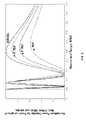
- the focal lengthis made negative, that is the radius of curvature of the phase front is convex instead of concave, the behavior of the normalized boresight power density behaves as shown in FIG. 3 .
- the poweris dispersed by the convex phase front and, as shown in FIG. 3 , the power density becomes lower as the negative focal length becomes more convex.
- the focal lengthis negative, as in FIG. 3 , the far field performance is seriously degraded. Thus, one would never use a negative focal length for a far field application.
- the complexity of the “spot” power density distribution in the near fieldis illustrated in FIG. 2 .
- the power density of a circular aperture with an infinite focusis plotted as a function of the radial distance from boresight for normalized ranges (R/Rnf) of 0.05, 0.10, 0.15, 0.20 and 0.25. Because of the circular symmetry, the beam profile is a figure of revolution of the plots shown in FIG. 2 .
- the pattern of the power density in the beamis quite variable as a function of range. In addition, for all ranges the total power of the beam is confined to about the same outer diameter although the distribution is non-uniform.
- Aperture type microwave transmitting antennasare usually designed for far field operation.
- systems designed for near field operationsuch as active denial technology.
- the shape and power density distribution of the radiated beam in the near fieldis complicated and varies considerably as a function of range, aperture shape, focal length, illumination, and phase distribution. While it is computationally possible to program the focal length of the aperture to achieve a more uniform power density distribution at selected ranges within the near field, it has heretofore required an aperture phased array of hundreds of thousands of elements or a precisely mechanically deformable aperture.
- An embodiment of the present inventionprovides a simple and inexpensive means for controlling the near field (Fresnel zone) characteristics of microwave transmitting antennas.
- the antenna apertureis divided into two sections with the inner section connected to the outer section by a small number of transducers that can be individually driven by a programmable driver.
- the transducersare used to vary the relative position of the inner section of the antenna aperture with respect to the outer section of the antenna aperture, approximating a concave or convex shape. Controlling the effective radius of curvature of the spherical phase front (focal length) at the antenna aperture controls the spot characteristics within the near field of the antenna.
- this embodimentcan also vary the tilt angle of the inner section to control the off axis position of the radiated beam or to trace out a scan pattern.
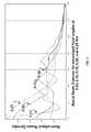
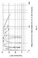
- FIG. 1is a plot of the boresight power density (W/m 2 ) vs. range normalized to the near field boundary of a disc aperture as in FIG. 4 with zero displacement of the inner disc.
- FIG. 2is a plot of normalized power density vs. radial beam distance for normalized ranges of 0.05, 0.10, 0.15, 0.20 and 0.25 Rnf, focal length is infinite.
- FIG. 3is a plot of normalized boresight power density of a circular aperture vs. normalized range for normalized focal lengths of ⁇ 1.0, ⁇ 3.0, ⁇ 5.0 (Rnf) and infinite.
- FIG. 4is a plot of normalized boresight power density of a circular aperture as a function of normalized range for normalized focal lengths of 0.25, 0.5, 1.0, 2.0 and 100 (Rnf).
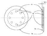
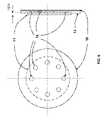
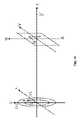
- FIG. 5shows three views of a circular aperture with a movable center section.
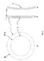
- FIG. 6is a diagram of a possible embodiment of the invention having two concentric disc apertures with the inner disc being displaced from the outer disc by means of transducers.
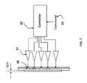
- FIG. 7is a diagram showing a typical arrangement for controlling the transducers of FIG. 6 .
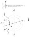
- FIG. 8is a diagram showing the ability to tilt the center disc and to vary the angular position of the maximum tilt.
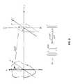
- FIG. 9is a diagram and general equation for calculation of the power density due to radiation from an aperture antenna.
- FIG. 10shows the geometry for the calculation of the power density due to radiation from the aperture antenna of FIG. 5 .
- FIG. 11is the general equation for the calculation of the power density due to radiation from the aperture antenna of FIG. 5 .
- FIG. 12is a plot of the boresight power density (W/m 2 ) vs. range for central disc displacements of 0, ⁇ 15, ⁇ 30, and ⁇ 45 degrees.
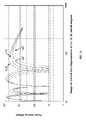
- FIG. 13is a plot of the boresight power density (W/m 2 ) vs. range for central disc displacements of 0, 15, 30, and 45 degrees.
- the near field of an aperture antennais comprised of a non-radiating reactive region in the space immediately surrounding the antenna and the radiating near field region referred to as the Fresnel region, the region of primary interest in the following discussion.
- This regionextends from the outer boundary of the reactive region given approximately by: R rr ⁇ 0.62 ⁇ ( D 3 / ⁇ ) where D is the largest dimension of the antenna and ⁇ is the transmitting wavelength.
- the outer boundary of the Fresnel regionis approximately given by: R nf ⁇ D 2 / ⁇ which for the earlier example would give an approximate range of 11 to 333 meters.
- the inventionprovides for this type of modulation in addition to the capability of controlling the steady spot characteristic.
- To accomplish this preciselyis a difficult and costly task to implement.
- Precise implementationwould require an aperture antenna fabricated from hundreds of thousands of individual phase controlled elements or a precision physically deformable aperture.
- the phased array approachis costly and prohibitively complex.
- the implementation of a precisely mechanically deformable apertureis also a very difficult and complex task.
- analysisshows that a simple approximation of the phase front radius of curvature modulation produces the desired effect as well as the precisely modulated phase front radius of curvature modulation.
- This approximate method of modulating the phase front radiusis very easily implemented and is the basis of the invention.
- the aperture antennamay be of any type that is illuminated externally or internally and emits a phase front to form a beam.
- the center section 2 of the aperture 1is such that it may be displaced normal to the plane of the aperture plate 1 . In the initial resting position the center section 2 is in the same plane as the outer fixed part of the aperture plate 1 and the effective radius of curvature is infinite.
- the surface of the aperture plate 1approximates a convex shape 3 .
- transducers 12are placed around the center disc 11 of the antenna assembly as shown in FIG. 6 .
- the transducers 12are mounted on the central disc 11 and attached to the aperture plate 10 .
- the center disc 11is itself attached to a frame 13 that is connected to the outer ring of the antenna plate 10 .
- the transducers 12may be piezoelectric, electromagnetic, or any other suitable type.
- the maximum throw of the transducer, ⁇ ps,should be a maximum of about one wavelength, or about 3-mm at a frequency of 100 GHz.
- the transducer drive amplifiers 21are programmed by a controller 22 that receives commands 23 from a system computer, operator or some appropriate source, and determines the displacement, ⁇ ps, based on a look up file, which is included in the controller 22 , relating the spot characteristic to the range of interest.
- the transducersmay also be programmed to provide a tilt, ⁇ T, to the central disc 31 .
- the axis of the tilt 32may be controlled to assume any orientation or to vary in time. This would permit the transmitted beam to point off axis or to trace out a scan pattern.
- the resulting characteristics of the displacements and tiltsare analyzed in the following paragraphs.
- the power density at a point in a target plane at rangecan be calculated using scalar potential theory.
- the general case equation and geometryare shown in FIG. 9 .
- the equation in FIG. 9assumes that the aperture is uniformly illuminated. This equation can be adapted to any shape aperture and also for non-uniform illumination by those skilled in the art.
- FIG. 9the geometry has been adapted to the geometry of an embodiment of the invention as shown in FIG. 5 .
- the equation of FIG. 9has been likewise adapted (see FIG. 10 ) to the geometry of the FIG. 5 embodiment.
- the over all coordinate system of FIG. 10is x-y-z.
- the aperture calculationsare in polar coordinates because of the circular symmetry.
- the computations in the target planeare in Cartesian coordinates referred to the v-w plane.
- Ddiameter of the outer disc
- D1diameter of the inner disc
- ⁇ psis the displacement of the inner disc from the outer disc
- PNscaling factor to relate the power density on the aperture to the field point.
- the power density profiles of the beammay be calculated for any displacement, ⁇ ps, and at any range R.
- the boresight power densityis shown in FIG. 1 with the central disc ( 2 of FIG. 5 ) having zero displacement.
- the first maximum encountered as the range decreases from the far-field regionis commonly referred to as the “Fresnel maximum”.
- the transition between near-field and far-fieldtakes place between this maximum and the normalized range of 1.0.
- the frequencyis 100 GHz
- the outside diameteris 1 meter
- the disc diameteris 0.707 m
- the poweris 1-kW with uniform illumination for this figure.
- the frequencyis 100 GHz
- the outside diameteris 1 meter
- the disc diameteris 0.707 m
- the poweris 1-kW with uniform illumination for this figure.
- FIGS. 1 , 3 , 4 , 12 , and 13are of the power density on the boresight.
- the power density profile of the beam or spot profile across the entire cross-sectionis calculated by adapting the FIG. 11 equation.
- the variation of the displacementgreatly affects the profile of the beam.
- the beam profile at 60 meters range as in FIG. 14has a null at the center, and peaks at a beam radius of about 1.8-m with an amplitude of about 1500 W/m 2 .
- the beam profileassumes a central peak and becomes a well formed pencil beam with the intensity concentrated within a radius of about 0.1 m and a peak amplitude of 8500 W/m 2 to 9000 W/m 2 .
- a 180° displacement of the discis equivalent to one half wavelength, or at 100 GHz the value is 1.5-mm.
- This magnitude of displacementis easily achieved with electromechanical transducers.
- electromechanical transducersThere are several suitable types of transducer including electromagnetic and piezoelectric types. A typical implementation of the invention would use several transducers, the exact number depending on the size of the inner disc.
- a tiltWhen a tilt is introduced to the inner disc position as illustrated in FIG. 8 , it affects the beam in that it is no longer rotationally symmetric.
- the tilting of the discis easily accomplished by programming the transducers 12 in FIG. 6 .
- the tilt orientation angle 32 in FIG. 8is also controlled in the same manner and, in addition, a complex combination of displacement, tilt and tilt orientation angle is achievable as a function of time.
Landscapes
- Variable-Direction Aerials And Aerial Arrays (AREA)
Abstract
Description
The conditions under which this invention was made are such as to entitle the Government of the United States under paragraph I(a) of Executive Order 10096, as represented by the Secretary of the Air Force, to the entire right, title and interest therein, including foreign rights.
This invention relates generally to the field of antennas and more specifically provides a means of control and optimization of the near field behavior of a microwave transmitting antenna.
Microwave transmitting antennas of the aperture type or equivalent operating at millimeter wavelengths have an equivalent aperture diameter that is many wavelengths that defines a near field region extending as far as hundreds of meters. The near field range (Rnf) of an antenna is defined as a range that is less than Rnf≈D2/λ. This is referred to as the near field boundary. D is the equivalent diameter of the antenna and A is the wavelength, all quantities being in meters. For example, an antenna with a diameter of 1 meter, at a wavelength of 0.003 meters (i.e. 100 GHz), the near field boundary is 333.33 meters. At ranges greater than the near field boundary, i.e. in the far field region, the behavior of the beam formed by the radiation from the antenna is well defined and has an intensity that falls off as the inverse square of the range. Most microwave systems, such as radar and communications, operate over ranges that are exclusively in the far field and near field performance is not a consideration.
There are systems that operate in the near field, such as Active Denial Technology (ADT). In the near field the shape and power density distribution of the radiated beam is complicated and changes considerably as a function of range, aperture shape, focal length, illumination amplitude and phase distribution.
An aperture antenna is one that has an aperture through or from which the electromagnetic fields pass to form a radiate beam or field. Any antenna can be described in terms of an equivalent aperture, thus in general the aperture concept is very broad. To simplify much of the analysis a circular aperture antenna is used to explain the qualitative performance characteristics in a somewhat general manner. However, the shape of the aperture does have an important impact in the near field and will be dealt with as required. Unless otherwise stated, an aperture of diameter D operating at a wavelength λ is used as the basis of analysis. In addition to the shape, wavelength, and diameter, the aperture also has another attribute, focal length, f. The focal length is defined as the radius of curvature of the spherical phase front at the aperture.
For the applications under consideration it is desirable to provide a nearly uniform power density distribution, bounded by a minimum and maximum level, over a target area for a continuous variation of range from a few meters from the antenna to a maximum of tens or hundreds of meters. The near field power density of a circular aperture with uniform illumination has a peak on boresight at a typical normalized range on the order of Rnf/6 to Rnf/4 depending primarily on the focal length and shape of the aperture. The first peak of the power intensity on boresight, as the range is decreased from the near field boundary is called the Fresnel maximum. This characteristic is illustrated inFIG. 1 . The radial power intensity of the spot is illustrated inFIG. 2 . As the focal length is reduced, the power density peak rises and the range of the peak decreases. At ranges closer than the Fresnel maximum peak the power density on boresight has numerous nulls and the shape of the “spot” develops various patterns of rings. As the range increases beyond the Fresnel maximum the “spot” has a central concentration and gradually transitions into the far field where the power density falls off as the inverse square of the range.
When the focal length is made negative, that is the radius of curvature of the phase front is convex instead of concave, the behavior of the normalized boresight power density behaves as shown inFIG. 3 . As expected, the power is dispersed by the convex phase front and, as shown inFIG. 3 , the power density becomes lower as the negative focal length becomes more convex. When the focal length is negative, as inFIG. 3 , the far field performance is seriously degraded. Thus, one would never use a negative focal length for a far field application.
The complexity of the “spot” power density distribution in the near field is illustrated inFIG. 2 . The power density of a circular aperture with an infinite focus is plotted as a function of the radial distance from boresight for normalized ranges (R/Rnf) of 0.05, 0.10, 0.15, 0.20 and 0.25. Because of the circular symmetry, the beam profile is a figure of revolution of the plots shown inFIG. 2 . The pattern of the power density in the beam is quite variable as a function of range. In addition, for all ranges the total power of the beam is confined to about the same outer diameter although the distribution is non-uniform.
These characteristics are not ideal for applications that require a concentration of the beam power that is confined to an area and does not vary greatly in magnitude over the concentration area. It is desirable to have control of the spot characteristics. In principle it is computationally possible to program the focal length of the aperture such that a more uniform power density distribution is achieved at selected ranges. This is very difficult to implement in that it would require an aperture phased array of hundreds of thousands of elements or a precisely mechanically deformable aperture. Neither of these options is feasible as a practical matter.
How to accomplish a more uniform power density distribution and control of the spot characteristics in the near field region using a practical approach is the subject of the present invention.
Aperture type microwave transmitting antennas are usually designed for far field operation. However, there are systems designed for near field operation, such as active denial technology. The shape and power density distribution of the radiated beam in the near field is complicated and varies considerably as a function of range, aperture shape, focal length, illumination, and phase distribution. While it is computationally possible to program the focal length of the aperture to achieve a more uniform power density distribution at selected ranges within the near field, it has heretofore required an aperture phased array of hundreds of thousands of elements or a precisely mechanically deformable aperture.
An embodiment of the present invention provides a simple and inexpensive means for controlling the near field (Fresnel zone) characteristics of microwave transmitting antennas. The antenna aperture is divided into two sections with the inner section connected to the outer section by a small number of transducers that can be individually driven by a programmable driver. The transducers are used to vary the relative position of the inner section of the antenna aperture with respect to the outer section of the antenna aperture, approximating a concave or convex shape. Controlling the effective radius of curvature of the spherical phase front (focal length) at the antenna aperture controls the spot characteristics within the near field of the antenna. Furthermore, this embodiment can also vary the tilt angle of the inner section to control the off axis position of the radiated beam or to trace out a scan pattern.
The near field of an aperture antenna is comprised of a non-radiating reactive region in the space immediately surrounding the antenna and the radiating near field region referred to as the Fresnel region, the region of primary interest in the following discussion. This region extends from the outer boundary of the reactive region given approximately by:
Rrr<0.62√(D3/λ)
where D is the largest dimension of the antenna and λ is the transmitting wavelength. The outer boundary of the Fresnel region is approximately given by:
Rnf≈D2/λ
which for the earlier example would give an approximate range of 11 to 333 meters.
Rrr<0.62√(D3/λ)
where D is the largest dimension of the antenna and λ is the transmitting wavelength. The outer boundary of the Fresnel region is approximately given by:
Rnf≈D2/λ
which for the earlier example would give an approximate range of 11 to 333 meters.
It has been shown above that conventional aperture antennas have non-uniform power density distributions in the near field region and are, therefore, poor in performance for applications that require a concentrated beam that is reasonably uniform over the beam area. It has also been shown that if one can control the focal length or the radius of curvature of the phase front on the array, the spot characteristics can be controlled at ranges within the near field of the aperture. This type of application requirement can be satisfied if the power intensity profile can be modulated such that the average power over the beam diameter is constant even if the instantaneous profile has non-uniform variations. This is based on the thermal time constant of the target being longer than the modulation rate of the power intensity profile and providing the averaging function.
The invention provides for this type of modulation in addition to the capability of controlling the steady spot characteristic. As illustrated inFIG. 2 ,FIG. 3 , andFIG. 4 , it is possible to modulate the power density and beam profile by varying the radius of curvature of the phase front at the aperture. To accomplish this precisely is a difficult and costly task to implement. Precise implementation would require an aperture antenna fabricated from hundreds of thousands of individual phase controlled elements or a precision physically deformable aperture. The phased array approach is costly and prohibitively complex. The implementation of a precisely mechanically deformable aperture is also a very difficult and complex task. However, analysis shows that a simple approximation of the phase front radius of curvature modulation produces the desired effect as well as the precisely modulated phase front radius of curvature modulation.
This approximate method of modulating the phase front radius is very easily implemented and is the basis of the invention. To explain, consider a circular aperture that is divided into two sections, anaperture plate 1 of diameter D is fixed at its outer rim and a moveablecentral section 2 of diameter D/√2, as inFIG. 5 . The aperture antenna may be of any type that is illuminated externally or internally and emits a phase front to form a beam. For simplicity of explanation a flat aperture with an infinite focus is assumed. Thecenter section 2 of theaperture 1 is such that it may be displaced normal to the plane of theaperture plate 1. In the initial resting position thecenter section 2 is in the same plane as the outer fixed part of theaperture plate 1 and the effective radius of curvature is infinite. When thecentral part 2 of the aperture is displaced to the left, as shown inFIG. 5 c, the surface of theaperture plate 1 approximates aconvex shape 3.
When thecenter section 2 is displaced by various amounts in terms of fractions of a wavelength, λ, of the operating frequency, the phase of the radiation from theaperture surface 3 is shifted. This shift changes the radiation characteristics from those experienced when there is no shift or equivalently when the aperture consists of a single uniform flat disc.
One implementation of the invention is achieved by placingtransducers 12 around thecenter disc 11 of the antenna assembly as shown inFIG. 6 . Thetransducers 12 are mounted on thecentral disc 11 and attached to theaperture plate 10. Thecenter disc 11 is itself attached to aframe 13 that is connected to the outer ring of theantenna plate 10. Thetransducers 12 may be piezoelectric, electromagnetic, or any other suitable type. The maximum throw of the transducer, Δps, should be a maximum of about one wavelength, or about 3-mm at a frequency of 100 GHz.
InFIG. 7 , thetransducer drive amplifiers 21 are programmed by acontroller 22 that receives commands23 from a system computer, operator or some appropriate source, and determines the displacement, Δps, based on a look up file, which is included in thecontroller 22, relating the spot characteristic to the range of interest.
As shown inFIG. 8 , in addition to implementing a linear displacement, Δps, of the innercentral disc 31 normal to the plane of theaperture plate 30, the transducers may also be programmed to provide a tilt, ΔT, to thecentral disc 31. Furthermore, the axis of thetilt 32 may be controlled to assume any orientation or to vary in time. This would permit the transmitted beam to point off axis or to trace out a scan pattern.
The resulting characteristics of the displacements and tilts are analyzed in the following paragraphs. The power density at a point in a target plane at range can be calculated using scalar potential theory. The general case equation and geometry are shown inFIG. 9 . The equation inFIG. 9 assumes that the aperture is uniformly illuminated. This equation can be adapted to any shape aperture and also for non-uniform illumination by those skilled in the art.
InFIG. 9 the geometry has been adapted to the geometry of an embodiment of the invention as shown inFIG. 5 . The equation ofFIG. 9 has been likewise adapted (seeFIG. 10 ) to the geometry of theFIG. 5 embodiment.
The over all coordinate system ofFIG. 10 is x-y-z. The aperture calculations are in polar coordinates because of the circular symmetry. The computations in the target plane are in Cartesian coordinates referred to the v-w plane. Referring to the equation ofFIG. 11 , D=diameter of the outer disc; D1=diameter of the inner disc; Δps is the displacement of the inner disc from the outer disc; and PN=scaling factor to relate the power density on the aperture to the field point. Using theFIG. 11 equation, the power density profiles of the beam may be calculated for any displacement, Δps, and at any range R.
For reference purposes the boresight power density is shown inFIG. 1 with the central disc (2 ofFIG. 5 ) having zero displacement. InFIG. 11 the range is normalized to the near field boundary (NFB=D2/λ), the frequency is 100 GHz, the outside diameter of the aperture plate is 1 meter, the inner disc diameter is 0.707 m, and the power is 1-kW with uniform illumination.
The first maximum encountered as the range decreases from the far-field region (at a normalized range of about 0.25 in theFIG. 1 plot) is commonly referred to as the “Fresnel maximum”. The transition between near-field and far-field takes place between this maximum and the normalized range of 1.0.
When the displacement Δps, expressed in equivalent degrees, (seeFIG. 12 ) is negative, the effect is that of decreasing the focal length of the aperture, or equivalently, a concave curvature of the phase front (aperture plate concave curvature). As the displacement Δps becomes increasingly negative, the boresight Fresnel peak amplitude increases and moves closer in range to the aperture, as shown inFIG. 12 . This is equivalent to decreasing the focal length, f, of the aperture. This is verified by comparison withFIG. 3 .FIG. 12 is a plot of the boresight power density (W/m2) vs. the range for central disc displacements of 0.0, −15, −30, and −45 degrees based on λ=360 degrees. The frequency is 100 GHz, the outside diameter is 1 meter, the disc diameter is 0.707 m, and the power is 1-kW with uniform illumination for this figure.
When the displacement is positive it approximates distorting the phase front in a convex manner. Intuitively one might think that this would disperse the beam power and the boresight intensity would fall off at all ranges as the convex curvature increased. This is true in the far field. The Fresnel maximum is also affected in that it decreases in amplitude and moves out in range. However, the first maximum to the left of the Fresnel peak increases in amplitude and also moves out in range.
When the displacement, Δps, of the inner disc is positive the result is the approximation of a convex phase front (aperture plate convex curvature). This behavior is shown inFIG. 13 for positive displacements of the inner disc that result in an approximate convex phase front. ComparingFIG. 13 toFIG. 2 , the behavior is similar in that when there is a decrease in the focal length or precise radius of curvature as inFIG. 2 , or a decrease in the approximate focal length as inFIG. 13 . That is, the Fresnel peak moves inward in range and increases in amplitude. And, the first peak to the left of the Fresnel peak moves inward in range and decreases in amplitude. Therefore, in terms of effect, the disc movement or modulation in this embodiment of the invention is essentially equivalent to that of a precisely shaped radius of curvature.
The effect of varying the displacement Δps in the positive direction is shown inFIG. 13 . The Fresnel maxim shifts to the right and decreases the amplitude. Also, the amplitude peak to the left of the Fresnel peak grows in amplitude and shifts slightly to the right. The effect is equivalent to that shown inFIG. 3 where the focal length is negative.FIG. 13 is a plot of the boresight power density (W/m2) vs. the range for central disc displacements of 0.0, 15, 30, and 45 degrees based on λ=360 degrees. The frequency is 100 GHz, the outside diameter is 1 meter, the disc diameter is 0.707 m, and the power is 1-kW with uniform illumination for this figure.
The plots inFIGS. 1 ,3,4,12, and13 are of the power density on the boresight. Of interest is the power density profile of the beam or spot profile across the entire cross-section. This is calculated by adapting theFIG. 11 equation. An example is shown inFIG. 14 , which shows the radial power profile at a range of 60 meters for inner disc displacements ranging between ±120° referred to an electrical wavelength, λ=360°. The variation of the displacement greatly affects the profile of the beam. With no displacement, 0.00, the beam profile at 60 meters range as inFIG. 14 , has a null at the center, and peaks at a beam radius of about 1.8-m with an amplitude of about 1500 W/m2. When the displacement is on the order of 80° to 120°, the beam profile assumes a central peak and becomes a well formed pencil beam with the intensity concentrated within a radius of about 0.1 m and a peak amplitude of 8500 W/m2to 9000 W/m2.
A 180° displacement of the disc is equivalent to one half wavelength, or at 100 GHz the value is 1.5-mm. This magnitude of displacement is easily achieved with electromechanical transducers. There are several suitable types of transducer including electromagnetic and piezoelectric types. A typical implementation of the invention would use several transducers, the exact number depending on the size of the inner disc.
When a tilt is introduced to the inner disc position as illustrated inFIG. 8 , it affects the beam in that it is no longer rotationally symmetric. The tilting of the disc is easily accomplished by programming thetransducers 12 inFIG. 6 . Thetilt orientation angle 32 inFIG. 8 is also controlled in the same manner and, in addition, a complex combination of displacement, tilt and tilt orientation angle is achievable as a function of time.
Claims (3)
1. A mechanism for varying the focal length of an aperture type transmitting antenna having an operating frequency in the microwave band capable of being illuminated externally or internally and of emitting a phase front to form a beam and having a fixed aperture outer rim, the mechanism comprised of:
a. a first flexible microwave antenna aperture plate of equivalent aperture diameter D fixed to said fixed aperture outer rim;
b. a second microwave antenna plate of equivalent aperture diameter of approximately D/√2 adjacent, parallel to, and centered on said first aperture plate;
c. a plurality of transducers placed near the outer edge of said second plate, connecting said first and second plate, and capable of linearly displacing said first plate with respect to said second plate;
d. a frame connected to a fixed outer rim of said second plate and to said first plate outer rim, thereby fixing said second plate's position with respect to said first plate; and
e. means for commanding the displacement of said transducers to change the displacement between said first and second plates, thereby altering the curvature of said first plate to control the transmitted beam shape, direction, and power density in the Fresnel zone.
2. The mechanism ofclaim 1 , wherein the maximum throw of said transducers is approximately one wavelength of the operating frequency.
3. The mechanism ofclaim 1 , wherein the means of commanding the displacement of said transducers is a controller that receives commands based on a look-up file relating the beam characteristics to the range of interest.
Priority Applications (1)
| Application Number | Priority Date | Filing Date | Title |
|---|---|---|---|
| US11/539,886US7301508B1 (en) | 2006-10-10 | 2006-10-10 | Optimization of near field antenna characteristics by aperture modulation |
Applications Claiming Priority (1)
| Application Number | Priority Date | Filing Date | Title |
|---|---|---|---|
| US11/539,886US7301508B1 (en) | 2006-10-10 | 2006-10-10 | Optimization of near field antenna characteristics by aperture modulation |
Publications (1)
| Publication Number | Publication Date |
|---|---|
| US7301508B1true US7301508B1 (en) | 2007-11-27 |
Family
ID=38721968
Family Applications (1)
| Application Number | Title | Priority Date | Filing Date |
|---|---|---|---|
| US11/539,886Expired - Fee RelatedUS7301508B1 (en) | 2006-10-10 | 2006-10-10 | Optimization of near field antenna characteristics by aperture modulation |
Country Status (1)
| Country | Link |
|---|---|
| US (1) | US7301508B1 (en) |
Cited By (129)
| Publication number | Priority date | Publication date | Assignee | Title |
|---|---|---|---|---|
| US9445483B2 (en)* | 2013-07-30 | 2016-09-13 | Koninklijke Philips N.V. | Lighting device and luminaire comprising an integrated antenna |
| US9667317B2 (en) | 2015-06-15 | 2017-05-30 | At&T Intellectual Property I, L.P. | Method and apparatus for providing security using network traffic adjustments |
| US20170155193A1 (en)* | 2015-11-30 | 2017-06-01 | Elwha Llc | Beam pattern projection for metamaterial antennas |
| US20170155192A1 (en)* | 2015-11-30 | 2017-06-01 | Elwha Llc | Beam pattern synthesis for metamaterial antennas |
| US9674711B2 (en) | 2013-11-06 | 2017-06-06 | At&T Intellectual Property I, L.P. | Surface-wave communications and methods thereof |
| US9685992B2 (en) | 2014-10-03 | 2017-06-20 | At&T Intellectual Property I, L.P. | Circuit panel network and methods thereof |
| US9705610B2 (en) | 2014-10-21 | 2017-07-11 | At&T Intellectual Property I, L.P. | Transmission device with impairment compensation and methods for use therewith |
| US9705561B2 (en) | 2015-04-24 | 2017-07-11 | At&T Intellectual Property I, L.P. | Directional coupling device and methods for use therewith |
| US9722318B2 (en) | 2015-07-14 | 2017-08-01 | At&T Intellectual Property I, L.P. | Method and apparatus for coupling an antenna to a device |
| US9729197B2 (en) | 2015-10-01 | 2017-08-08 | At&T Intellectual Property I, L.P. | Method and apparatus for communicating network management traffic over a network |
| US9735833B2 (en) | 2015-07-31 | 2017-08-15 | At&T Intellectual Property I, L.P. | Method and apparatus for communications management in a neighborhood network |
| US9742462B2 (en) | 2014-12-04 | 2017-08-22 | At&T Intellectual Property I, L.P. | Transmission medium and communication interfaces and methods for use therewith |
| US9742521B2 (en) | 2014-11-20 | 2017-08-22 | At&T Intellectual Property I, L.P. | Transmission device with mode division multiplexing and methods for use therewith |
| US9749053B2 (en) | 2015-07-23 | 2017-08-29 | At&T Intellectual Property I, L.P. | Node device, repeater and methods for use therewith |
| US9749013B2 (en) | 2015-03-17 | 2017-08-29 | At&T Intellectual Property I, L.P. | Method and apparatus for reducing attenuation of electromagnetic waves guided by a transmission medium |
| US9748626B2 (en) | 2015-05-14 | 2017-08-29 | At&T Intellectual Property I, L.P. | Plurality of cables having different cross-sectional shapes which are bundled together to form a transmission medium |
| US9769020B2 (en) | 2014-10-21 | 2017-09-19 | At&T Intellectual Property I, L.P. | Method and apparatus for responding to events affecting communications in a communication network |
| US9769128B2 (en) | 2015-09-28 | 2017-09-19 | At&T Intellectual Property I, L.P. | Method and apparatus for encryption of communications over a network |
| US9768833B2 (en) | 2014-09-15 | 2017-09-19 | At&T Intellectual Property I, L.P. | Method and apparatus for sensing a condition in a transmission medium of electromagnetic waves |
| US9780834B2 (en) | 2014-10-21 | 2017-10-03 | At&T Intellectual Property I, L.P. | Method and apparatus for transmitting electromagnetic waves |
| US9787412B2 (en) | 2015-06-25 | 2017-10-10 | At&T Intellectual Property I, L.P. | Methods and apparatus for inducing a fundamental wave mode on a transmission medium |
| US9793951B2 (en) | 2015-07-15 | 2017-10-17 | At&T Intellectual Property I, L.P. | Method and apparatus for launching a wave mode that mitigates interference |
| US9793955B2 (en) | 2015-04-24 | 2017-10-17 | At&T Intellectual Property I, Lp | Passive electrical coupling device and methods for use therewith |
| US9793954B2 (en) | 2015-04-28 | 2017-10-17 | At&T Intellectual Property I, L.P. | Magnetic coupling device and methods for use therewith |
| US9800327B2 (en) | 2014-11-20 | 2017-10-24 | At&T Intellectual Property I, L.P. | Apparatus for controlling operations of a communication device and methods thereof |
| US9820146B2 (en) | 2015-06-12 | 2017-11-14 | At&T Intellectual Property I, L.P. | Method and apparatus for authentication and identity management of communicating devices |
| WO2017198157A1 (en)* | 2016-05-18 | 2017-11-23 | 上海跃盛信息技术有限公司 | Solid-surface reflector for microwave reflection |
| US9838896B1 (en) | 2016-12-09 | 2017-12-05 | At&T Intellectual Property I, L.P. | Method and apparatus for assessing network coverage |
| US9838078B2 (en) | 2015-07-31 | 2017-12-05 | At&T Intellectual Property I, L.P. | Method and apparatus for exchanging communication signals |
| US9847566B2 (en) | 2015-07-14 | 2017-12-19 | At&T Intellectual Property I, L.P. | Method and apparatus for adjusting a field of a signal to mitigate interference |
| US9847850B2 (en) | 2014-10-14 | 2017-12-19 | At&T Intellectual Property I, L.P. | Method and apparatus for adjusting a mode of communication in a communication network |
| US9853342B2 (en) | 2015-07-14 | 2017-12-26 | At&T Intellectual Property I, L.P. | Dielectric transmission medium connector and methods for use therewith |
| US9860075B1 (en) | 2016-08-26 | 2018-01-02 | At&T Intellectual Property I, L.P. | Method and communication node for broadband distribution |
| US9866309B2 (en) | 2015-06-03 | 2018-01-09 | At&T Intellectual Property I, Lp | Host node device and methods for use therewith |
| US9866276B2 (en) | 2014-10-10 | 2018-01-09 | At&T Intellectual Property I, L.P. | Method and apparatus for arranging communication sessions in a communication system |
| US9865911B2 (en) | 2015-06-25 | 2018-01-09 | At&T Intellectual Property I, L.P. | Waveguide system for slot radiating first electromagnetic waves that are combined into a non-fundamental wave mode second electromagnetic wave on a transmission medium |
| US9871282B2 (en) | 2015-05-14 | 2018-01-16 | At&T Intellectual Property I, L.P. | At least one transmission medium having a dielectric surface that is covered at least in part by a second dielectric |
| US9871283B2 (en) | 2015-07-23 | 2018-01-16 | At&T Intellectual Property I, Lp | Transmission medium having a dielectric core comprised of plural members connected by a ball and socket configuration |
| US9871558B2 (en) | 2014-10-21 | 2018-01-16 | At&T Intellectual Property I, L.P. | Guided-wave transmission device and methods for use therewith |
| US9876605B1 (en) | 2016-10-21 | 2018-01-23 | At&T Intellectual Property I, L.P. | Launcher and coupling system to support desired guided wave mode |
| US9876570B2 (en) | 2015-02-20 | 2018-01-23 | At&T Intellectual Property I, Lp | Guided-wave transmission device with non-fundamental mode propagation and methods for use therewith |
| US9876264B2 (en) | 2015-10-02 | 2018-01-23 | At&T Intellectual Property I, Lp | Communication system, guided wave switch and methods for use therewith |
| US9882257B2 (en) | 2015-07-14 | 2018-01-30 | At&T Intellectual Property I, L.P. | Method and apparatus for launching a wave mode that mitigates interference |
| US9887447B2 (en) | 2015-05-14 | 2018-02-06 | At&T Intellectual Property I, L.P. | Transmission medium having multiple cores and methods for use therewith |
| US9893795B1 (en) | 2016-12-07 | 2018-02-13 | At&T Intellectual Property I, Lp | Method and repeater for broadband distribution |
| US9904535B2 (en) | 2015-09-14 | 2018-02-27 | At&T Intellectual Property I, L.P. | Method and apparatus for distributing software |
| US9906269B2 (en) | 2014-09-17 | 2018-02-27 | At&T Intellectual Property I, L.P. | Monitoring and mitigating conditions in a communication network |
| US9911020B1 (en) | 2016-12-08 | 2018-03-06 | At&T Intellectual Property I, L.P. | Method and apparatus for tracking via a radio frequency identification device |
| US9912033B2 (en) | 2014-10-21 | 2018-03-06 | At&T Intellectual Property I, Lp | Guided wave coupler, coupling module and methods for use therewith |
| US9913139B2 (en) | 2015-06-09 | 2018-03-06 | At&T Intellectual Property I, L.P. | Signal fingerprinting for authentication of communicating devices |
| US9912027B2 (en) | 2015-07-23 | 2018-03-06 | At&T Intellectual Property I, L.P. | Method and apparatus for exchanging communication signals |
| US9912381B2 (en) | 2015-06-03 | 2018-03-06 | At&T Intellectual Property I, Lp | Network termination and methods for use therewith |
| US9917341B2 (en) | 2015-05-27 | 2018-03-13 | At&T Intellectual Property I, L.P. | Apparatus and method for launching electromagnetic waves and for modifying radial dimensions of the propagating electromagnetic waves |
| US9929755B2 (en) | 2015-07-14 | 2018-03-27 | At&T Intellectual Property I, L.P. | Method and apparatus for coupling an antenna to a device |
| US9927517B1 (en) | 2016-12-06 | 2018-03-27 | At&T Intellectual Property I, L.P. | Apparatus and methods for sensing rainfall |
| US9948333B2 (en) | 2015-07-23 | 2018-04-17 | At&T Intellectual Property I, L.P. | Method and apparatus for wireless communications to mitigate interference |
| US9954286B2 (en) | 2014-10-21 | 2018-04-24 | At&T Intellectual Property I, L.P. | Guided-wave transmission device with non-fundamental mode propagation and methods for use therewith |
| US9954287B2 (en) | 2014-11-20 | 2018-04-24 | At&T Intellectual Property I, L.P. | Apparatus for converting wireless signals and electromagnetic waves and methods thereof |
| US9967173B2 (en) | 2015-07-31 | 2018-05-08 | At&T Intellectual Property I, L.P. | Method and apparatus for authentication and identity management of communicating devices |
| US9973416B2 (en) | 2014-10-02 | 2018-05-15 | At&T Intellectual Property I, L.P. | Method and apparatus that provides fault tolerance in a communication network |
| US9973940B1 (en) | 2017-02-27 | 2018-05-15 | At&T Intellectual Property I, L.P. | Apparatus and methods for dynamic impedance matching of a guided wave launcher |
| US9991580B2 (en) | 2016-10-21 | 2018-06-05 | At&T Intellectual Property I, L.P. | Launcher and coupling system for guided wave mode cancellation |
| US9998870B1 (en) | 2016-12-08 | 2018-06-12 | At&T Intellectual Property I, L.P. | Method and apparatus for proximity sensing |
| US9997819B2 (en) | 2015-06-09 | 2018-06-12 | At&T Intellectual Property I, L.P. | Transmission medium and method for facilitating propagation of electromagnetic waves via a core |
| US9999038B2 (en) | 2013-05-31 | 2018-06-12 | At&T Intellectual Property I, L.P. | Remote distributed antenna system |
| US10009067B2 (en) | 2014-12-04 | 2018-06-26 | At&T Intellectual Property I, L.P. | Method and apparatus for configuring a communication interface |
| US10020844B2 (en) | 2016-12-06 | 2018-07-10 | T&T Intellectual Property I, L.P. | Method and apparatus for broadcast communication via guided waves |
| US10027397B2 (en) | 2016-12-07 | 2018-07-17 | At&T Intellectual Property I, L.P. | Distributed antenna system and methods for use therewith |
| US10033108B2 (en) | 2015-07-14 | 2018-07-24 | At&T Intellectual Property I, L.P. | Apparatus and methods for generating an electromagnetic wave having a wave mode that mitigates interference |
| US10044409B2 (en) | 2015-07-14 | 2018-08-07 | At&T Intellectual Property I, L.P. | Transmission medium and methods for use therewith |
| US10051630B2 (en) | 2013-05-31 | 2018-08-14 | At&T Intellectual Property I, L.P. | Remote distributed antenna system |
| US10069535B2 (en) | 2016-12-08 | 2018-09-04 | At&T Intellectual Property I, L.P. | Apparatus and methods for launching electromagnetic waves having a certain electric field structure |
| US10069185B2 (en) | 2015-06-25 | 2018-09-04 | At&T Intellectual Property I, L.P. | Methods and apparatus for inducing a non-fundamental wave mode on a transmission medium |
| US10090594B2 (en) | 2016-11-23 | 2018-10-02 | At&T Intellectual Property I, L.P. | Antenna system having structural configurations for assembly |
| US10090606B2 (en) | 2015-07-15 | 2018-10-02 | At&T Intellectual Property I, L.P. | Antenna system with dielectric array and methods for use therewith |
| US10103422B2 (en) | 2016-12-08 | 2018-10-16 | At&T Intellectual Property I, L.P. | Method and apparatus for mounting network devices |
| US10135145B2 (en) | 2016-12-06 | 2018-11-20 | At&T Intellectual Property I, L.P. | Apparatus and methods for generating an electromagnetic wave along a transmission medium |
| US10135147B2 (en) | 2016-10-18 | 2018-11-20 | At&T Intellectual Property I, L.P. | Apparatus and methods for launching guided waves via an antenna |
| US10135146B2 (en) | 2016-10-18 | 2018-11-20 | At&T Intellectual Property I, L.P. | Apparatus and methods for launching guided waves via circuits |
| US10139820B2 (en) | 2016-12-07 | 2018-11-27 | At&T Intellectual Property I, L.P. | Method and apparatus for deploying equipment of a communication system |
| US10148016B2 (en) | 2015-07-14 | 2018-12-04 | At&T Intellectual Property I, L.P. | Apparatus and methods for communicating utilizing an antenna array |
| US10168695B2 (en) | 2016-12-07 | 2019-01-01 | At&T Intellectual Property I, L.P. | Method and apparatus for controlling an unmanned aircraft |
| US10170840B2 (en) | 2015-07-14 | 2019-01-01 | At&T Intellectual Property I, L.P. | Apparatus and methods for sending or receiving electromagnetic signals |
| US10178445B2 (en) | 2016-11-23 | 2019-01-08 | At&T Intellectual Property I, L.P. | Methods, devices, and systems for load balancing between a plurality of waveguides |
| US10205655B2 (en) | 2015-07-14 | 2019-02-12 | At&T Intellectual Property I, L.P. | Apparatus and methods for communicating utilizing an antenna array and multiple communication paths |
| US10224634B2 (en) | 2016-11-03 | 2019-03-05 | At&T Intellectual Property I, L.P. | Methods and apparatus for adjusting an operational characteristic of an antenna |
| US10225025B2 (en) | 2016-11-03 | 2019-03-05 | At&T Intellectual Property I, L.P. | Method and apparatus for detecting a fault in a communication system |
| US10243784B2 (en) | 2014-11-20 | 2019-03-26 | At&T Intellectual Property I, L.P. | System for generating topology information and methods thereof |
| US10243270B2 (en) | 2016-12-07 | 2019-03-26 | At&T Intellectual Property I, L.P. | Beam adaptive multi-feed dielectric antenna system and methods for use therewith |
| US10264586B2 (en) | 2016-12-09 | 2019-04-16 | At&T Mobility Ii Llc | Cloud-based packet controller and methods for use therewith |
| US10291334B2 (en) | 2016-11-03 | 2019-05-14 | At&T Intellectual Property I, L.P. | System for detecting a fault in a communication system |
| US10298293B2 (en) | 2017-03-13 | 2019-05-21 | At&T Intellectual Property I, L.P. | Apparatus of communication utilizing wireless network devices |
| US10305190B2 (en) | 2016-12-01 | 2019-05-28 | At&T Intellectual Property I, L.P. | Reflecting dielectric antenna system and methods for use therewith |
| US10312567B2 (en) | 2016-10-26 | 2019-06-04 | At&T Intellectual Property I, L.P. | Launcher with planar strip antenna and methods for use therewith |
| US10320586B2 (en) | 2015-07-14 | 2019-06-11 | At&T Intellectual Property I, L.P. | Apparatus and methods for generating non-interfering electromagnetic waves on an insulated transmission medium |
| US10326689B2 (en) | 2016-12-08 | 2019-06-18 | At&T Intellectual Property I, L.P. | Method and system for providing alternative communication paths |
| US10326494B2 (en) | 2016-12-06 | 2019-06-18 | At&T Intellectual Property I, L.P. | Apparatus for measurement de-embedding and methods for use therewith |
| US10340603B2 (en) | 2016-11-23 | 2019-07-02 | At&T Intellectual Property I, L.P. | Antenna system having shielded structural configurations for assembly |
| US10340601B2 (en) | 2016-11-23 | 2019-07-02 | At&T Intellectual Property I, L.P. | Multi-antenna system and methods for use therewith |
| US10341142B2 (en) | 2015-07-14 | 2019-07-02 | At&T Intellectual Property I, L.P. | Apparatus and methods for generating non-interfering electromagnetic waves on an uninsulated conductor |
| US10340573B2 (en) | 2016-10-26 | 2019-07-02 | At&T Intellectual Property I, L.P. | Launcher with cylindrical coupling device and methods for use therewith |
| US10340600B2 (en) | 2016-10-18 | 2019-07-02 | At&T Intellectual Property I, L.P. | Apparatus and methods for launching guided waves via plural waveguide systems |
| US10340983B2 (en) | 2016-12-09 | 2019-07-02 | At&T Intellectual Property I, L.P. | Method and apparatus for surveying remote sites via guided wave communications |
| US10355367B2 (en) | 2015-10-16 | 2019-07-16 | At&T Intellectual Property I, L.P. | Antenna structure for exchanging wireless signals |
| US10359749B2 (en) | 2016-12-07 | 2019-07-23 | At&T Intellectual Property I, L.P. | Method and apparatus for utilities management via guided wave communication |
| US10361489B2 (en) | 2016-12-01 | 2019-07-23 | At&T Intellectual Property I, L.P. | Dielectric dish antenna system and methods for use therewith |
| US10374316B2 (en) | 2016-10-21 | 2019-08-06 | At&T Intellectual Property I, L.P. | System and dielectric antenna with non-uniform dielectric |
| US10382976B2 (en) | 2016-12-06 | 2019-08-13 | At&T Intellectual Property I, L.P. | Method and apparatus for managing wireless communications based on communication paths and network device positions |
| US10389029B2 (en) | 2016-12-07 | 2019-08-20 | At&T Intellectual Property I, L.P. | Multi-feed dielectric antenna system with core selection and methods for use therewith |
| US10389037B2 (en) | 2016-12-08 | 2019-08-20 | At&T Intellectual Property I, L.P. | Apparatus and methods for selecting sections of an antenna array and use therewith |
| US10411356B2 (en) | 2016-12-08 | 2019-09-10 | At&T Intellectual Property I, L.P. | Apparatus and methods for selectively targeting communication devices with an antenna array |
| US10439675B2 (en) | 2016-12-06 | 2019-10-08 | At&T Intellectual Property I, L.P. | Method and apparatus for repeating guided wave communication signals |
| US10446936B2 (en) | 2016-12-07 | 2019-10-15 | At&T Intellectual Property I, L.P. | Multi-feed dielectric antenna system and methods for use therewith |
| US10498044B2 (en) | 2016-11-03 | 2019-12-03 | At&T Intellectual Property I, L.P. | Apparatus for configuring a surface of an antenna |
| US10530505B2 (en) | 2016-12-08 | 2020-01-07 | At&T Intellectual Property I, L.P. | Apparatus and methods for launching electromagnetic waves along a transmission medium |
| US10535928B2 (en) | 2016-11-23 | 2020-01-14 | At&T Intellectual Property I, L.P. | Antenna system and methods for use therewith |
| US10547348B2 (en) | 2016-12-07 | 2020-01-28 | At&T Intellectual Property I, L.P. | Method and apparatus for switching transmission mediums in a communication system |
| US10601494B2 (en) | 2016-12-08 | 2020-03-24 | At&T Intellectual Property I, L.P. | Dual-band communication device and method for use therewith |
| US10637149B2 (en) | 2016-12-06 | 2020-04-28 | At&T Intellectual Property I, L.P. | Injection molded dielectric antenna and methods for use therewith |
| US10650940B2 (en) | 2015-05-15 | 2020-05-12 | At&T Intellectual Property I, L.P. | Transmission medium having a conductive material and methods for use therewith |
| US10694379B2 (en) | 2016-12-06 | 2020-06-23 | At&T Intellectual Property I, L.P. | Waveguide system with device-based authentication and methods for use therewith |
| US10727599B2 (en) | 2016-12-06 | 2020-07-28 | At&T Intellectual Property I, L.P. | Launcher with slot antenna and methods for use therewith |
| US10755542B2 (en) | 2016-12-06 | 2020-08-25 | At&T Intellectual Property I, L.P. | Method and apparatus for surveillance via guided wave communication |
| US10777873B2 (en) | 2016-12-08 | 2020-09-15 | At&T Intellectual Property I, L.P. | Method and apparatus for mounting network devices |
| US10797781B2 (en) | 2015-06-03 | 2020-10-06 | At&T Intellectual Property I, L.P. | Client node device and methods for use therewith |
| US10811767B2 (en) | 2016-10-21 | 2020-10-20 | At&T Intellectual Property I, L.P. | System and dielectric antenna with convex dielectric radome |
| US10819035B2 (en) | 2016-12-06 | 2020-10-27 | At&T Intellectual Property I, L.P. | Launcher with helical antenna and methods for use therewith |
| US10916969B2 (en) | 2016-12-08 | 2021-02-09 | At&T Intellectual Property I, L.P. | Method and apparatus for providing power using an inductive coupling |
| US10938108B2 (en) | 2016-12-08 | 2021-03-02 | At&T Intellectual Property I, L.P. | Frequency selective multi-feed dielectric antenna system and methods for use therewith |
Citations (4)
| Publication number | Priority date | Publication date | Assignee | Title |
|---|---|---|---|---|
| US4571594A (en)* | 1983-09-02 | 1986-02-18 | The United States Of America As Represented By The Secretary Of The Air Force | Directional antenna system having sidelobe suppression |
| US4750002A (en)* | 1986-09-12 | 1988-06-07 | Harris Corporation | Antenna panel having adjustable supports to improve surface accuracy |
| US4845510A (en)* | 1987-08-10 | 1989-07-04 | Hughes Aircraft Company | Reflector surface adjustment structure |
| US5307082A (en)* | 1992-10-28 | 1994-04-26 | North Carolina State University | Electrostatically shaped membranes |
- 2006
- 2006-10-10USUS11/539,886patent/US7301508B1/ennot_activeExpired - Fee Related
Patent Citations (4)
| Publication number | Priority date | Publication date | Assignee | Title |
|---|---|---|---|---|
| US4571594A (en)* | 1983-09-02 | 1986-02-18 | The United States Of America As Represented By The Secretary Of The Air Force | Directional antenna system having sidelobe suppression |
| US4750002A (en)* | 1986-09-12 | 1988-06-07 | Harris Corporation | Antenna panel having adjustable supports to improve surface accuracy |
| US4845510A (en)* | 1987-08-10 | 1989-07-04 | Hughes Aircraft Company | Reflector surface adjustment structure |
| US5307082A (en)* | 1992-10-28 | 1994-04-26 | North Carolina State University | Electrostatically shaped membranes |
Non-Patent Citations (1)
| Title |
|---|
| USAF Active Denial Technology, http://deps.org/news/active<SUB>-</SUB>denial<SUB>-</SUB>tech.doc. |
Cited By (148)
| Publication number | Priority date | Publication date | Assignee | Title |
|---|---|---|---|---|
| US9999038B2 (en) | 2013-05-31 | 2018-06-12 | At&T Intellectual Property I, L.P. | Remote distributed antenna system |
| US10051630B2 (en) | 2013-05-31 | 2018-08-14 | At&T Intellectual Property I, L.P. | Remote distributed antenna system |
| US9445483B2 (en)* | 2013-07-30 | 2016-09-13 | Koninklijke Philips N.V. | Lighting device and luminaire comprising an integrated antenna |
| RU2672052C2 (en)* | 2013-07-30 | 2018-11-09 | Филипс Лайтинг Холдинг Б.В. | Lighting device and lamps containing integrated antenna |
| US9674711B2 (en) | 2013-11-06 | 2017-06-06 | At&T Intellectual Property I, L.P. | Surface-wave communications and methods thereof |
| US9768833B2 (en) | 2014-09-15 | 2017-09-19 | At&T Intellectual Property I, L.P. | Method and apparatus for sensing a condition in a transmission medium of electromagnetic waves |
| US9906269B2 (en) | 2014-09-17 | 2018-02-27 | At&T Intellectual Property I, L.P. | Monitoring and mitigating conditions in a communication network |
| US10063280B2 (en) | 2014-09-17 | 2018-08-28 | At&T Intellectual Property I, L.P. | Monitoring and mitigating conditions in a communication network |
| US9973416B2 (en) | 2014-10-02 | 2018-05-15 | At&T Intellectual Property I, L.P. | Method and apparatus that provides fault tolerance in a communication network |
| US9685992B2 (en) | 2014-10-03 | 2017-06-20 | At&T Intellectual Property I, L.P. | Circuit panel network and methods thereof |
| US9866276B2 (en) | 2014-10-10 | 2018-01-09 | At&T Intellectual Property I, L.P. | Method and apparatus for arranging communication sessions in a communication system |
| US9847850B2 (en) | 2014-10-14 | 2017-12-19 | At&T Intellectual Property I, L.P. | Method and apparatus for adjusting a mode of communication in a communication network |
| US9780834B2 (en) | 2014-10-21 | 2017-10-03 | At&T Intellectual Property I, L.P. | Method and apparatus for transmitting electromagnetic waves |
| US9960808B2 (en) | 2014-10-21 | 2018-05-01 | At&T Intellectual Property I, L.P. | Guided-wave transmission device and methods for use therewith |
| US9871558B2 (en) | 2014-10-21 | 2018-01-16 | At&T Intellectual Property I, L.P. | Guided-wave transmission device and methods for use therewith |
| US9876587B2 (en) | 2014-10-21 | 2018-01-23 | At&T Intellectual Property I, L.P. | Transmission device with impairment compensation and methods for use therewith |
| US9705610B2 (en) | 2014-10-21 | 2017-07-11 | At&T Intellectual Property I, L.P. | Transmission device with impairment compensation and methods for use therewith |
| US9769020B2 (en) | 2014-10-21 | 2017-09-19 | At&T Intellectual Property I, L.P. | Method and apparatus for responding to events affecting communications in a communication network |
| US9912033B2 (en) | 2014-10-21 | 2018-03-06 | At&T Intellectual Property I, Lp | Guided wave coupler, coupling module and methods for use therewith |
| US9954286B2 (en) | 2014-10-21 | 2018-04-24 | At&T Intellectual Property I, L.P. | Guided-wave transmission device with non-fundamental mode propagation and methods for use therewith |
| US9800327B2 (en) | 2014-11-20 | 2017-10-24 | At&T Intellectual Property I, L.P. | Apparatus for controlling operations of a communication device and methods thereof |
| US9742521B2 (en) | 2014-11-20 | 2017-08-22 | At&T Intellectual Property I, L.P. | Transmission device with mode division multiplexing and methods for use therewith |
| US10243784B2 (en) | 2014-11-20 | 2019-03-26 | At&T Intellectual Property I, L.P. | System for generating topology information and methods thereof |
| US9954287B2 (en) | 2014-11-20 | 2018-04-24 | At&T Intellectual Property I, L.P. | Apparatus for converting wireless signals and electromagnetic waves and methods thereof |
| US9749083B2 (en) | 2014-11-20 | 2017-08-29 | At&T Intellectual Property I, L.P. | Transmission device with mode division multiplexing and methods for use therewith |
| US9742462B2 (en) | 2014-12-04 | 2017-08-22 | At&T Intellectual Property I, L.P. | Transmission medium and communication interfaces and methods for use therewith |
| US10009067B2 (en) | 2014-12-04 | 2018-06-26 | At&T Intellectual Property I, L.P. | Method and apparatus for configuring a communication interface |
| US9876570B2 (en) | 2015-02-20 | 2018-01-23 | At&T Intellectual Property I, Lp | Guided-wave transmission device with non-fundamental mode propagation and methods for use therewith |
| US9876571B2 (en) | 2015-02-20 | 2018-01-23 | At&T Intellectual Property I, Lp | Guided-wave transmission device with non-fundamental mode propagation and methods for use therewith |
| US9749013B2 (en) | 2015-03-17 | 2017-08-29 | At&T Intellectual Property I, L.P. | Method and apparatus for reducing attenuation of electromagnetic waves guided by a transmission medium |
| US9793955B2 (en) | 2015-04-24 | 2017-10-17 | At&T Intellectual Property I, Lp | Passive electrical coupling device and methods for use therewith |
| US9705561B2 (en) | 2015-04-24 | 2017-07-11 | At&T Intellectual Property I, L.P. | Directional coupling device and methods for use therewith |
| US9831912B2 (en) | 2015-04-24 | 2017-11-28 | At&T Intellectual Property I, Lp | Directional coupling device and methods for use therewith |
| US10224981B2 (en) | 2015-04-24 | 2019-03-05 | At&T Intellectual Property I, Lp | Passive electrical coupling device and methods for use therewith |
| US9793954B2 (en) | 2015-04-28 | 2017-10-17 | At&T Intellectual Property I, L.P. | Magnetic coupling device and methods for use therewith |
| US9748626B2 (en) | 2015-05-14 | 2017-08-29 | At&T Intellectual Property I, L.P. | Plurality of cables having different cross-sectional shapes which are bundled together to form a transmission medium |
| US9887447B2 (en) | 2015-05-14 | 2018-02-06 | At&T Intellectual Property I, L.P. | Transmission medium having multiple cores and methods for use therewith |
| US9871282B2 (en) | 2015-05-14 | 2018-01-16 | At&T Intellectual Property I, L.P. | At least one transmission medium having a dielectric surface that is covered at least in part by a second dielectric |
| US10650940B2 (en) | 2015-05-15 | 2020-05-12 | At&T Intellectual Property I, L.P. | Transmission medium having a conductive material and methods for use therewith |
| US9917341B2 (en) | 2015-05-27 | 2018-03-13 | At&T Intellectual Property I, L.P. | Apparatus and method for launching electromagnetic waves and for modifying radial dimensions of the propagating electromagnetic waves |
| US9866309B2 (en) | 2015-06-03 | 2018-01-09 | At&T Intellectual Property I, Lp | Host node device and methods for use therewith |
| US9912382B2 (en) | 2015-06-03 | 2018-03-06 | At&T Intellectual Property I, Lp | Network termination and methods for use therewith |
| US9912381B2 (en) | 2015-06-03 | 2018-03-06 | At&T Intellectual Property I, Lp | Network termination and methods for use therewith |
| US10812174B2 (en) | 2015-06-03 | 2020-10-20 | At&T Intellectual Property I, L.P. | Client node device and methods for use therewith |
| US10050697B2 (en) | 2015-06-03 | 2018-08-14 | At&T Intellectual Property I, L.P. | Host node device and methods for use therewith |
| US9967002B2 (en) | 2015-06-03 | 2018-05-08 | At&T Intellectual I, Lp | Network termination and methods for use therewith |
| US10797781B2 (en) | 2015-06-03 | 2020-10-06 | At&T Intellectual Property I, L.P. | Client node device and methods for use therewith |
| US9935703B2 (en) | 2015-06-03 | 2018-04-03 | At&T Intellectual Property I, L.P. | Host node device and methods for use therewith |
| US9913139B2 (en) | 2015-06-09 | 2018-03-06 | At&T Intellectual Property I, L.P. | Signal fingerprinting for authentication of communicating devices |
| US9997819B2 (en) | 2015-06-09 | 2018-06-12 | At&T Intellectual Property I, L.P. | Transmission medium and method for facilitating propagation of electromagnetic waves via a core |
| US9820146B2 (en) | 2015-06-12 | 2017-11-14 | At&T Intellectual Property I, L.P. | Method and apparatus for authentication and identity management of communicating devices |
| US9667317B2 (en) | 2015-06-15 | 2017-05-30 | At&T Intellectual Property I, L.P. | Method and apparatus for providing security using network traffic adjustments |
| US10069185B2 (en) | 2015-06-25 | 2018-09-04 | At&T Intellectual Property I, L.P. | Methods and apparatus for inducing a non-fundamental wave mode on a transmission medium |
| US9787412B2 (en) | 2015-06-25 | 2017-10-10 | At&T Intellectual Property I, L.P. | Methods and apparatus for inducing a fundamental wave mode on a transmission medium |
| US9865911B2 (en) | 2015-06-25 | 2018-01-09 | At&T Intellectual Property I, L.P. | Waveguide system for slot radiating first electromagnetic waves that are combined into a non-fundamental wave mode second electromagnetic wave on a transmission medium |
| US10205655B2 (en) | 2015-07-14 | 2019-02-12 | At&T Intellectual Property I, L.P. | Apparatus and methods for communicating utilizing an antenna array and multiple communication paths |
| US10320586B2 (en) | 2015-07-14 | 2019-06-11 | At&T Intellectual Property I, L.P. | Apparatus and methods for generating non-interfering electromagnetic waves on an insulated transmission medium |
| US10170840B2 (en) | 2015-07-14 | 2019-01-01 | At&T Intellectual Property I, L.P. | Apparatus and methods for sending or receiving electromagnetic signals |
| US10033108B2 (en) | 2015-07-14 | 2018-07-24 | At&T Intellectual Property I, L.P. | Apparatus and methods for generating an electromagnetic wave having a wave mode that mitigates interference |
| US10148016B2 (en) | 2015-07-14 | 2018-12-04 | At&T Intellectual Property I, L.P. | Apparatus and methods for communicating utilizing an antenna array |
| US9929755B2 (en) | 2015-07-14 | 2018-03-27 | At&T Intellectual Property I, L.P. | Method and apparatus for coupling an antenna to a device |
| US9853342B2 (en) | 2015-07-14 | 2017-12-26 | At&T Intellectual Property I, L.P. | Dielectric transmission medium connector and methods for use therewith |
| US9847566B2 (en) | 2015-07-14 | 2017-12-19 | At&T Intellectual Property I, L.P. | Method and apparatus for adjusting a field of a signal to mitigate interference |
| US9722318B2 (en) | 2015-07-14 | 2017-08-01 | At&T Intellectual Property I, L.P. | Method and apparatus for coupling an antenna to a device |
| US10341142B2 (en) | 2015-07-14 | 2019-07-02 | At&T Intellectual Property I, L.P. | Apparatus and methods for generating non-interfering electromagnetic waves on an uninsulated conductor |
| US10044409B2 (en) | 2015-07-14 | 2018-08-07 | At&T Intellectual Property I, L.P. | Transmission medium and methods for use therewith |
| US9882257B2 (en) | 2015-07-14 | 2018-01-30 | At&T Intellectual Property I, L.P. | Method and apparatus for launching a wave mode that mitigates interference |
| US9793951B2 (en) | 2015-07-15 | 2017-10-17 | At&T Intellectual Property I, L.P. | Method and apparatus for launching a wave mode that mitigates interference |
| US10090606B2 (en) | 2015-07-15 | 2018-10-02 | At&T Intellectual Property I, L.P. | Antenna system with dielectric array and methods for use therewith |
| US9806818B2 (en) | 2015-07-23 | 2017-10-31 | At&T Intellectual Property I, Lp | Node device, repeater and methods for use therewith |
| US9948333B2 (en) | 2015-07-23 | 2018-04-17 | At&T Intellectual Property I, L.P. | Method and apparatus for wireless communications to mitigate interference |
| US9912027B2 (en) | 2015-07-23 | 2018-03-06 | At&T Intellectual Property I, L.P. | Method and apparatus for exchanging communication signals |
| US9749053B2 (en) | 2015-07-23 | 2017-08-29 | At&T Intellectual Property I, L.P. | Node device, repeater and methods for use therewith |
| US9871283B2 (en) | 2015-07-23 | 2018-01-16 | At&T Intellectual Property I, Lp | Transmission medium having a dielectric core comprised of plural members connected by a ball and socket configuration |
| US9967173B2 (en) | 2015-07-31 | 2018-05-08 | At&T Intellectual Property I, L.P. | Method and apparatus for authentication and identity management of communicating devices |
| US9838078B2 (en) | 2015-07-31 | 2017-12-05 | At&T Intellectual Property I, L.P. | Method and apparatus for exchanging communication signals |
| US9735833B2 (en) | 2015-07-31 | 2017-08-15 | At&T Intellectual Property I, L.P. | Method and apparatus for communications management in a neighborhood network |
| US9904535B2 (en) | 2015-09-14 | 2018-02-27 | At&T Intellectual Property I, L.P. | Method and apparatus for distributing software |
| US9769128B2 (en) | 2015-09-28 | 2017-09-19 | At&T Intellectual Property I, L.P. | Method and apparatus for encryption of communications over a network |
| US9729197B2 (en) | 2015-10-01 | 2017-08-08 | At&T Intellectual Property I, L.P. | Method and apparatus for communicating network management traffic over a network |
| US9876264B2 (en) | 2015-10-02 | 2018-01-23 | At&T Intellectual Property I, Lp | Communication system, guided wave switch and methods for use therewith |
| US10355367B2 (en) | 2015-10-16 | 2019-07-16 | At&T Intellectual Property I, L.P. | Antenna structure for exchanging wireless signals |
| US20170155193A1 (en)* | 2015-11-30 | 2017-06-01 | Elwha Llc | Beam pattern projection for metamaterial antennas |
| US10050345B2 (en)* | 2015-11-30 | 2018-08-14 | Elwha Llc | Beam pattern projection for metamaterial antennas |
| US10050344B2 (en)* | 2015-11-30 | 2018-08-14 | Elwha Llc | Beam pattern synthesis for metamaterial antennas |
| US20170155192A1 (en)* | 2015-11-30 | 2017-06-01 | Elwha Llc | Beam pattern synthesis for metamaterial antennas |
| US10741913B2 (en)* | 2015-11-30 | 2020-08-11 | The Invention Science Fund I, Llc | Beam pattern synthesis for metamaterial antennas |
| WO2017198157A1 (en)* | 2016-05-18 | 2017-11-23 | 上海跃盛信息技术有限公司 | Solid-surface reflector for microwave reflection |
| CN107404006A (en)* | 2016-05-18 | 2017-11-28 | 上海跃盛信息技术有限公司 | A kind of solid face reflector for microwave reflection |
| US9860075B1 (en) | 2016-08-26 | 2018-01-02 | At&T Intellectual Property I, L.P. | Method and communication node for broadband distribution |
| US10135146B2 (en) | 2016-10-18 | 2018-11-20 | At&T Intellectual Property I, L.P. | Apparatus and methods for launching guided waves via circuits |
| US10340600B2 (en) | 2016-10-18 | 2019-07-02 | At&T Intellectual Property I, L.P. | Apparatus and methods for launching guided waves via plural waveguide systems |
| US10135147B2 (en) | 2016-10-18 | 2018-11-20 | At&T Intellectual Property I, L.P. | Apparatus and methods for launching guided waves via an antenna |
| US9991580B2 (en) | 2016-10-21 | 2018-06-05 | At&T Intellectual Property I, L.P. | Launcher and coupling system for guided wave mode cancellation |
| US10374316B2 (en) | 2016-10-21 | 2019-08-06 | At&T Intellectual Property I, L.P. | System and dielectric antenna with non-uniform dielectric |
| US9876605B1 (en) | 2016-10-21 | 2018-01-23 | At&T Intellectual Property I, L.P. | Launcher and coupling system to support desired guided wave mode |
| US10811767B2 (en) | 2016-10-21 | 2020-10-20 | At&T Intellectual Property I, L.P. | System and dielectric antenna with convex dielectric radome |
| US10312567B2 (en) | 2016-10-26 | 2019-06-04 | At&T Intellectual Property I, L.P. | Launcher with planar strip antenna and methods for use therewith |
| US10340573B2 (en) | 2016-10-26 | 2019-07-02 | At&T Intellectual Property I, L.P. | Launcher with cylindrical coupling device and methods for use therewith |
| US10224634B2 (en) | 2016-11-03 | 2019-03-05 | At&T Intellectual Property I, L.P. | Methods and apparatus for adjusting an operational characteristic of an antenna |
| US10498044B2 (en) | 2016-11-03 | 2019-12-03 | At&T Intellectual Property I, L.P. | Apparatus for configuring a surface of an antenna |
| US10225025B2 (en) | 2016-11-03 | 2019-03-05 | At&T Intellectual Property I, L.P. | Method and apparatus for detecting a fault in a communication system |
| US10291334B2 (en) | 2016-11-03 | 2019-05-14 | At&T Intellectual Property I, L.P. | System for detecting a fault in a communication system |
| US10178445B2 (en) | 2016-11-23 | 2019-01-08 | At&T Intellectual Property I, L.P. | Methods, devices, and systems for load balancing between a plurality of waveguides |
| US10340601B2 (en) | 2016-11-23 | 2019-07-02 | At&T Intellectual Property I, L.P. | Multi-antenna system and methods for use therewith |
| US10340603B2 (en) | 2016-11-23 | 2019-07-02 | At&T Intellectual Property I, L.P. | Antenna system having shielded structural configurations for assembly |
| US10090594B2 (en) | 2016-11-23 | 2018-10-02 | At&T Intellectual Property I, L.P. | Antenna system having structural configurations for assembly |
| US10535928B2 (en) | 2016-11-23 | 2020-01-14 | At&T Intellectual Property I, L.P. | Antenna system and methods for use therewith |
| US11139580B2 (en) | 2016-11-23 | 2021-10-05 | At&T Intellectual Property I, L.P. | Multi-antenna system and methods for use therewith |
| US10305190B2 (en) | 2016-12-01 | 2019-05-28 | At&T Intellectual Property I, L.P. | Reflecting dielectric antenna system and methods for use therewith |
| US10361489B2 (en) | 2016-12-01 | 2019-07-23 | At&T Intellectual Property I, L.P. | Dielectric dish antenna system and methods for use therewith |
| US10637149B2 (en) | 2016-12-06 | 2020-04-28 | At&T Intellectual Property I, L.P. | Injection molded dielectric antenna and methods for use therewith |
| US10326494B2 (en) | 2016-12-06 | 2019-06-18 | At&T Intellectual Property I, L.P. | Apparatus for measurement de-embedding and methods for use therewith |
| US10694379B2 (en) | 2016-12-06 | 2020-06-23 | At&T Intellectual Property I, L.P. | Waveguide system with device-based authentication and methods for use therewith |
| US10727599B2 (en) | 2016-12-06 | 2020-07-28 | At&T Intellectual Property I, L.P. | Launcher with slot antenna and methods for use therewith |
| US10439675B2 (en) | 2016-12-06 | 2019-10-08 | At&T Intellectual Property I, L.P. | Method and apparatus for repeating guided wave communication signals |
| US10020844B2 (en) | 2016-12-06 | 2018-07-10 | T&T Intellectual Property I, L.P. | Method and apparatus for broadcast communication via guided waves |
| US10755542B2 (en) | 2016-12-06 | 2020-08-25 | At&T Intellectual Property I, L.P. | Method and apparatus for surveillance via guided wave communication |
| US10382976B2 (en) | 2016-12-06 | 2019-08-13 | At&T Intellectual Property I, L.P. | Method and apparatus for managing wireless communications based on communication paths and network device positions |
| US9927517B1 (en) | 2016-12-06 | 2018-03-27 | At&T Intellectual Property I, L.P. | Apparatus and methods for sensing rainfall |
| US10135145B2 (en) | 2016-12-06 | 2018-11-20 | At&T Intellectual Property I, L.P. | Apparatus and methods for generating an electromagnetic wave along a transmission medium |
| US10819035B2 (en) | 2016-12-06 | 2020-10-27 | At&T Intellectual Property I, L.P. | Launcher with helical antenna and methods for use therewith |
| US10359749B2 (en) | 2016-12-07 | 2019-07-23 | At&T Intellectual Property I, L.P. | Method and apparatus for utilities management via guided wave communication |
| US10547348B2 (en) | 2016-12-07 | 2020-01-28 | At&T Intellectual Property I, L.P. | Method and apparatus for switching transmission mediums in a communication system |
| US10389029B2 (en) | 2016-12-07 | 2019-08-20 | At&T Intellectual Property I, L.P. | Multi-feed dielectric antenna system with core selection and methods for use therewith |
| US10139820B2 (en) | 2016-12-07 | 2018-11-27 | At&T Intellectual Property I, L.P. | Method and apparatus for deploying equipment of a communication system |
| US10168695B2 (en) | 2016-12-07 | 2019-01-01 | At&T Intellectual Property I, L.P. | Method and apparatus for controlling an unmanned aircraft |
| US9893795B1 (en) | 2016-12-07 | 2018-02-13 | At&T Intellectual Property I, Lp | Method and repeater for broadband distribution |
| US10446936B2 (en) | 2016-12-07 | 2019-10-15 | At&T Intellectual Property I, L.P. | Multi-feed dielectric antenna system and methods for use therewith |
| US10027397B2 (en) | 2016-12-07 | 2018-07-17 | At&T Intellectual Property I, L.P. | Distributed antenna system and methods for use therewith |
| US10243270B2 (en) | 2016-12-07 | 2019-03-26 | At&T Intellectual Property I, L.P. | Beam adaptive multi-feed dielectric antenna system and methods for use therewith |
| US10326689B2 (en) | 2016-12-08 | 2019-06-18 | At&T Intellectual Property I, L.P. | Method and system for providing alternative communication paths |
| US10777873B2 (en) | 2016-12-08 | 2020-09-15 | At&T Intellectual Property I, L.P. | Method and apparatus for mounting network devices |
| US10601494B2 (en) | 2016-12-08 | 2020-03-24 | At&T Intellectual Property I, L.P. | Dual-band communication device and method for use therewith |
| US10103422B2 (en) | 2016-12-08 | 2018-10-16 | At&T Intellectual Property I, L.P. | Method and apparatus for mounting network devices |
| US9911020B1 (en) | 2016-12-08 | 2018-03-06 | At&T Intellectual Property I, L.P. | Method and apparatus for tracking via a radio frequency identification device |
| US10530505B2 (en) | 2016-12-08 | 2020-01-07 | At&T Intellectual Property I, L.P. | Apparatus and methods for launching electromagnetic waves along a transmission medium |
| US9998870B1 (en) | 2016-12-08 | 2018-06-12 | At&T Intellectual Property I, L.P. | Method and apparatus for proximity sensing |
| US10938108B2 (en) | 2016-12-08 | 2021-03-02 | At&T Intellectual Property I, L.P. | Frequency selective multi-feed dielectric antenna system and methods for use therewith |
| US10916969B2 (en) | 2016-12-08 | 2021-02-09 | At&T Intellectual Property I, L.P. | Method and apparatus for providing power using an inductive coupling |
| US10389037B2 (en) | 2016-12-08 | 2019-08-20 | At&T Intellectual Property I, L.P. | Apparatus and methods for selecting sections of an antenna array and use therewith |
| US10411356B2 (en) | 2016-12-08 | 2019-09-10 | At&T Intellectual Property I, L.P. | Apparatus and methods for selectively targeting communication devices with an antenna array |
| US10069535B2 (en) | 2016-12-08 | 2018-09-04 | At&T Intellectual Property I, L.P. | Apparatus and methods for launching electromagnetic waves having a certain electric field structure |
| US10340983B2 (en) | 2016-12-09 | 2019-07-02 | At&T Intellectual Property I, L.P. | Method and apparatus for surveying remote sites via guided wave communications |
| US9838896B1 (en) | 2016-12-09 | 2017-12-05 | At&T Intellectual Property I, L.P. | Method and apparatus for assessing network coverage |
| US10264586B2 (en) | 2016-12-09 | 2019-04-16 | At&T Mobility Ii Llc | Cloud-based packet controller and methods for use therewith |
| US9973940B1 (en) | 2017-02-27 | 2018-05-15 | At&T Intellectual Property I, L.P. | Apparatus and methods for dynamic impedance matching of a guided wave launcher |
| US10298293B2 (en) | 2017-03-13 | 2019-05-21 | At&T Intellectual Property I, L.P. | Apparatus of communication utilizing wireless network devices |
Similar Documents
| Publication | Publication Date | Title |
|---|---|---|
| US7301508B1 (en) | Optimization of near field antenna characteristics by aperture modulation | |
| US3755815A (en) | Phased array fed lens antenna | |
| US9583840B1 (en) | Microwave zoom antenna using metal plate lenses | |
| EP2025045B1 (en) | Chip-lens array antenna system | |
| JP5290403B2 (en) | Small aperture interrogator antenna system using sum-difference orientation discrimination technique | |
| US4268831A (en) | Antenna for scanning a limited spatial sector | |
| CN109346843B (en) | Design method of space one-dimensional scanning lens antenna and beam scanning method | |
| EP3414793B1 (en) | Antenna system comprising dielectric lenses and method for aerial vehicles | |
| CN111817017B (en) | A Reflector Antenna Based on Arrayed Micro-displacement Control | |
| US8963774B1 (en) | Adaptive nulling for parasitic array antennas | |
| US5233356A (en) | Low sidelobe solid state array antenna apparatus and process for configuring an array antenna aperture | |
| KR101986048B1 (en) | A spatial microwave modulating device using active metasurface | |
| US8472121B2 (en) | Adjustable electromagnetic energy collimator | |
| WO1988001106A1 (en) | Low sidelobe solid state array antenna apparatus and process for configuring an array antenna aperture | |
| CN115836443A (en) | Annular gradient index lens for omnidirectional and sector antennas | |
| US8159410B2 (en) | Reflective antenna assembly | |
| US10050338B1 (en) | Variable focus microwave antenna | |
| EP4396905A1 (en) | Antenna assembly and communication system | |
| Elizarrarás et al. | Design of aperiodic spherical antenna arrays for wideband performance | |
| KR20210110009A (en) | WIRELESS POWER CHARGING APPARATUS FOR CHARGING IoT DEVICE | |
| KR102724494B1 (en) | Transmitarray antenna for simultaneous beam forming and focusing | |
| US2664508A (en) | Antenna | |
| Zhang et al. | A New Beam-Scanning Scheme of a 1-bit Uniform 1-D Antenna Array for Generating Uniform Field Distribution | |
| Marin et al. | Figure of merit for beam-steering antennas | |
| Huang et al. | Synthesis of low and equal-ripple sidelobe patterns in time-modulated circular antenna arrays |
Legal Events
| Date | Code | Title | Description |
|---|---|---|---|
| AS | Assignment | Owner name:THE GOVERNMENT OF THE UNITED STATES AS REPRESENTED Free format text:ASSIGNMENT OF ASSIGNORS INTEREST;ASSIGNOR:O'LOUGHLIN, JAMES P.;REEL/FRAME:018425/0503 Effective date:20061005 | |
| FPAY | Fee payment | Year of fee payment:4 | |
| REMI | Maintenance fee reminder mailed | ||
| LAPS | Lapse for failure to pay maintenance fees | ||
| STCH | Information on status: patent discontinuation | Free format text:PATENT EXPIRED DUE TO NONPAYMENT OF MAINTENANCE FEES UNDER 37 CFR 1.362 | |
| FP | Lapsed due to failure to pay maintenance fee | Effective date:20151127 |