US7300457B2 - Self-supporting metallic implantable grafts, compliant implantable medical devices and methods of making same - Google Patents
Self-supporting metallic implantable grafts, compliant implantable medical devices and methods of making sameDownload PDFInfo
- Publication number
- US7300457B2 US7300457B2US10/135,316US13531602AUS7300457B2US 7300457 B2US7300457 B2US 7300457B2US 13531602 AUS13531602 AUS 13531602AUS 7300457 B2US7300457 B2US 7300457B2
- Authority
- US
- United States
- Prior art keywords
- graft
- microperforations
- implantable
- graft according
- implantable medical
- Prior art date
- Legal status (The legal status is an assumption and is not a legal conclusion. Google has not performed a legal analysis and makes no representation as to the accuracy of the status listed.)
- Expired - Lifetime, expires
Links
- 238000000034methodMethods0.000titledescription26
- 229910052751metalInorganic materials0.000claimsdescription35
- 239000002184metalSubstances0.000claimsdescription35
- PXHVJJICTQNCMI-UHFFFAOYSA-NNickelChemical compound[Ni]PXHVJJICTQNCMI-UHFFFAOYSA-N0.000claimsdescription18
- RTAQQCXQSZGOHL-UHFFFAOYSA-NTitaniumChemical compound[Ti]RTAQQCXQSZGOHL-UHFFFAOYSA-N0.000claimsdescription10
- 239000010936titaniumSubstances0.000claimsdescription10
- 229910052719titaniumInorganic materials0.000claimsdescription10
- 229910052759nickelInorganic materials0.000claimsdescription9
- KDLHZDBZIXYQEI-UHFFFAOYSA-NPalladiumChemical compound[Pd]KDLHZDBZIXYQEI-UHFFFAOYSA-N0.000claimsdescription8
- 230000008859changeEffects0.000claimsdescription8
- BASFCYQUMIYNBI-UHFFFAOYSA-NplatinumChemical compound[Pt]BASFCYQUMIYNBI-UHFFFAOYSA-N0.000claimsdescription8
- 229910045601alloyInorganic materials0.000claimsdescription7
- 239000000956alloySubstances0.000claimsdescription7
- 239000004033plasticSubstances0.000claimsdescription7
- 229920003023plasticPolymers0.000claimsdescription7
- 229910052715tantalumInorganic materials0.000claimsdescription6
- GUVRBAGPIYLISA-UHFFFAOYSA-Ntantalum atomChemical compound[Ta]GUVRBAGPIYLISA-UHFFFAOYSA-N0.000claimsdescription6
- PCHJSUWPFVWCPO-UHFFFAOYSA-NgoldChemical compound[Au]PCHJSUWPFVWCPO-UHFFFAOYSA-N0.000claimsdescription5
- 229910052737goldInorganic materials0.000claimsdescription5
- 239000010931goldSubstances0.000claimsdescription5
- 239000007769metal materialSubstances0.000claimsdescription5
- VYZAMTAEIAYCRO-UHFFFAOYSA-NChromiumChemical compound[Cr]VYZAMTAEIAYCRO-UHFFFAOYSA-N0.000claimsdescription4
- FYYHWMGAXLPEAU-UHFFFAOYSA-NMagnesiumChemical compound[Mg]FYYHWMGAXLPEAU-UHFFFAOYSA-N0.000claimsdescription4
- ZOKXTWBITQBERF-UHFFFAOYSA-NMolybdenumChemical compound[Mo]ZOKXTWBITQBERF-UHFFFAOYSA-N0.000claimsdescription4
- XUIMIQQOPSSXEZ-UHFFFAOYSA-NSiliconChemical compound[Si]XUIMIQQOPSSXEZ-UHFFFAOYSA-N0.000claimsdescription4
- BQCADISMDOOEFD-UHFFFAOYSA-NSilverChemical compound[Ag]BQCADISMDOOEFD-UHFFFAOYSA-N0.000claimsdescription4
- QCWXUUIWCKQGHC-UHFFFAOYSA-NZirconiumChemical compound[Zr]QCWXUUIWCKQGHC-UHFFFAOYSA-N0.000claimsdescription4
- 229910052782aluminiumInorganic materials0.000claimsdescription4
- XAGFODPZIPBFFR-UHFFFAOYSA-NaluminiumChemical compound[Al]XAGFODPZIPBFFR-UHFFFAOYSA-N0.000claimsdescription4
- 229910052804chromiumInorganic materials0.000claimsdescription4
- 239000011651chromiumSubstances0.000claimsdescription4
- 229910017052cobaltInorganic materials0.000claimsdescription4
- 239000010941cobaltSubstances0.000claimsdescription4
- GUTLYIVDDKVIGB-UHFFFAOYSA-Ncobalt atomChemical compound[Co]GUTLYIVDDKVIGB-UHFFFAOYSA-N0.000claimsdescription4
- 229910052749magnesiumInorganic materials0.000claimsdescription4
- 239000011777magnesiumSubstances0.000claimsdescription4
- WPBNNNQJVZRUHP-UHFFFAOYSA-Lmanganese(2+);methyl n-[[2-(methoxycarbonylcarbamothioylamino)phenyl]carbamothioyl]carbamate;n-[2-(sulfidocarbothioylamino)ethyl]carbamodithioateChemical compound[Mn+2].[S-]C(=S)NCCNC([S-])=S.COC(=O)NC(=S)NC1=CC=CC=C1NC(=S)NC(=O)OCWPBNNNQJVZRUHP-UHFFFAOYSA-L0.000claimsdescription4
- 229910052750molybdenumInorganic materials0.000claimsdescription4
- 239000011733molybdenumSubstances0.000claimsdescription4
- 229910052758niobiumInorganic materials0.000claimsdescription4
- 239000010955niobiumSubstances0.000claimsdescription4
- GUCVJGMIXFAOAE-UHFFFAOYSA-Nniobium atomChemical compound[Nb]GUCVJGMIXFAOAE-UHFFFAOYSA-N0.000claimsdescription4
- 229910052763palladiumInorganic materials0.000claimsdescription4
- 229910052697platinumInorganic materials0.000claimsdescription4
- 229910052706scandiumInorganic materials0.000claimsdescription4
- SIXSYDAISGFNSX-UHFFFAOYSA-Nscandium atomChemical compound[Sc]SIXSYDAISGFNSX-UHFFFAOYSA-N0.000claimsdescription4
- 229910052710siliconInorganic materials0.000claimsdescription4
- 239000010703siliconSubstances0.000claimsdescription4
- 229910052709silverInorganic materials0.000claimsdescription4
- 239000004332silverSubstances0.000claimsdescription4
- 229910052720vanadiumInorganic materials0.000claimsdescription4
- 229910052726zirconiumInorganic materials0.000claimsdescription4
- LEONUFNNVUYDNQ-UHFFFAOYSA-Nvanadium atomChemical compound[V]LEONUFNNVUYDNQ-UHFFFAOYSA-N0.000claims2
- 239000000463materialSubstances0.000abstractdescription56
- 238000001771vacuum depositionMethods0.000abstractdescription20
- 238000000151depositionMethods0.000abstractdescription14
- 230000008021depositionEffects0.000abstractdescription13
- 230000002792vascularEffects0.000abstractdescription10
- 239000000560biocompatible materialSubstances0.000abstractdescription5
- 210000000988bone and boneAnatomy0.000abstractdescription2
- 210000003041ligamentAnatomy0.000abstractdescription2
- 239000012528membraneSubstances0.000abstractdescription2
- 210000005070sphincterAnatomy0.000abstractdescription2
- 210000002435tendonAnatomy0.000abstractdescription2
- 239000010408filmSubstances0.000description27
- 239000010410layerSubstances0.000description16
- 150000002739metalsChemical class0.000description12
- 230000005012migrationEffects0.000description12
- 238000013508migrationMethods0.000description12
- 239000000758substrateSubstances0.000description12
- 210000002889endothelial cellAnatomy0.000description11
- 238000004519manufacturing processMethods0.000description11
- 229920000642polymerPolymers0.000description11
- 238000000576coating methodMethods0.000description10
- 230000001413cellular effectEffects0.000description9
- 229910001000nickel titaniumInorganic materials0.000description9
- 239000011248coating agentSubstances0.000description8
- 230000008569processEffects0.000description8
- 238000001816coolingMethods0.000description7
- 210000004027cellAnatomy0.000description6
- 102000006495integrinsHuman genes0.000description6
- 108010044426integrinsProteins0.000description6
- 230000008901benefitEffects0.000description5
- 239000007789gasSubstances0.000description5
- 239000002243precursorSubstances0.000description5
- 238000012545processingMethods0.000description5
- 102000004169proteins and genesHuman genes0.000description5
- 108090000623proteins and genesProteins0.000description5
- WZUVPPKBWHMQCE-UHFFFAOYSA-NHaematoxylinChemical compoundC12=CC(O)=C(O)C=C2CC2(O)C1C1=CC=C(O)C(O)=C1OC2WZUVPPKBWHMQCE-UHFFFAOYSA-N0.000description4
- 241000282898Sus scrofaSpecies0.000description4
- 238000002679ablationMethods0.000description4
- 210000001715carotid arteryAnatomy0.000description4
- 239000000919ceramicSubstances0.000description4
- 238000009826distributionMethods0.000description4
- 238000005516engineering processMethods0.000description4
- 238000005530etchingMethods0.000description4
- 230000006870functionEffects0.000description4
- 238000001727in vivoMethods0.000description4
- 239000003446ligandSubstances0.000description4
- HLXZNVUGXRDIFK-UHFFFAOYSA-Nnickel titaniumChemical compound[Ti].[Ti].[Ti].[Ti].[Ti].[Ti].[Ti].[Ti].[Ti].[Ti].[Ti].[Ni].[Ni].[Ni].[Ni].[Ni].[Ni].[Ni].[Ni].[Ni].[Ni].[Ni].[Ni].[Ni].[Ni]HLXZNVUGXRDIFK-UHFFFAOYSA-N0.000description4
- 239000011148porous materialSubstances0.000description4
- 238000004544sputter depositionMethods0.000description4
- OKTJSMMVPCPJKN-UHFFFAOYSA-NCarbonChemical compound[C]OKTJSMMVPCPJKN-UHFFFAOYSA-N0.000description3
- RYGMFSIKBFXOCR-UHFFFAOYSA-NCopperChemical compound[Cu]RYGMFSIKBFXOCR-UHFFFAOYSA-N0.000description3
- 229910052799carbonInorganic materials0.000description3
- 238000006243chemical reactionMethods0.000description3
- 239000002131composite materialSubstances0.000description3
- 229910052802copperInorganic materials0.000description3
- 239000010949copperSubstances0.000description3
- 239000012530fluidSubstances0.000description3
- 210000001650focal adhesionAnatomy0.000description3
- 239000000203mixtureSubstances0.000description3
- 239000002245particleSubstances0.000description3
- 230000037361pathwayEffects0.000description3
- -1polytetrafluoroethylenePolymers0.000description3
- 229910001220stainless steelInorganic materials0.000description3
- 239000010935stainless steelSubstances0.000description3
- 239000010409thin filmSubstances0.000description3
- 238000003466weldingMethods0.000description3
- XKRFYHLGVUSROY-UHFFFAOYSA-NArgonChemical compound[Ar]XKRFYHLGVUSROY-UHFFFAOYSA-N0.000description2
- HTTJABKRGRZYRN-UHFFFAOYSA-NHeparinChemical compoundOC1C(NC(=O)C)C(O)OC(COS(O)(=O)=O)C1OC1C(OS(O)(=O)=O)C(O)C(OC2C(C(OS(O)(=O)=O)C(OC3C(C(O)C(O)C(O3)C(O)=O)OS(O)(=O)=O)C(CO)O2)NS(O)(=O)=O)C(C(O)=O)O1HTTJABKRGRZYRN-UHFFFAOYSA-N0.000description2
- 229910001362Ta alloysInorganic materials0.000description2
- 239000000853adhesiveSubstances0.000description2
- 230000001070adhesive effectEffects0.000description2
- 238000000137annealingMethods0.000description2
- 238000000889atomisationMethods0.000description2
- 230000015572biosynthetic processEffects0.000description2
- 230000017531blood circulationEffects0.000description2
- 230000015556catabolic processEffects0.000description2
- 230000021164cell adhesionEffects0.000description2
- 210000000170cell membraneAnatomy0.000description2
- 238000003486chemical etchingMethods0.000description2
- 230000004087circulationEffects0.000description2
- 238000006731degradation reactionMethods0.000description2
- 238000013461designMethods0.000description2
- 230000000694effectsEffects0.000description2
- YQGOJNYOYNNSMM-UHFFFAOYSA-NeosinChemical compound[Na+].OC(=O)C1=CC=CC=C1C1=C2C=C(Br)C(=O)C(Br)=C2OC2=C(Br)C(O)=C(Br)C=C21YQGOJNYOYNNSMM-UHFFFAOYSA-N0.000description2
- 239000003102growth factorSubstances0.000description2
- 230000035876healingEffects0.000description2
- 238000010438heat treatmentMethods0.000description2
- 229960002897heparinDrugs0.000description2
- 229920000669heparinPolymers0.000description2
- 238000000608laser ablationMethods0.000description2
- 238000003754machiningMethods0.000description2
- 229910001092metal group alloyInorganic materials0.000description2
- 239000000178monomerSubstances0.000description2
- 230000003287optical effectEffects0.000description2
- 238000005240physical vapour depositionMethods0.000description2
- 238000006116polymerization reactionMethods0.000description2
- 230000035755proliferationEffects0.000description2
- 230000005855radiationEffects0.000description2
- 229910000077silaneInorganic materials0.000description2
- 241000894007speciesSpecies0.000description2
- 238000005482strain hardeningMethods0.000description2
- WILOFBYLLUPEHC-UHFFFAOYSA-Ntantalum titanium zirconiumChemical compound[Ti].[Zr].[Ta]WILOFBYLLUPEHC-UHFFFAOYSA-N0.000description2
- 238000012876topographyMethods0.000description2
- GPPXJZIENCGNKB-UHFFFAOYSA-NvanadiumChemical compound[V]#[V]GPPXJZIENCGNKB-UHFFFAOYSA-N0.000description2
- 125000000391vinyl groupChemical group[H]C([*])=C([H])[H]0.000description2
- 229910020018Nb ZrInorganic materials0.000description1
- GRYLNZFGIOXLOG-UHFFFAOYSA-NNitric acidChemical compoundO[N+]([O-])=OGRYLNZFGIOXLOG-UHFFFAOYSA-N0.000description1
- 238000003723SmeltingMethods0.000description1
- 208000007536ThrombosisDiseases0.000description1
- 229910001069Ti alloyInorganic materials0.000description1
- 239000000654additiveSubstances0.000description1
- 230000000996additive effectEffects0.000description1
- 230000002411adverseEffects0.000description1
- 125000003275alpha amino acid groupChemical group0.000description1
- 238000002399angioplastyMethods0.000description1
- 239000006117anti-reflective coatingSubstances0.000description1
- 230000002785anti-thrombosisEffects0.000description1
- 239000003146anticoagulant agentSubstances0.000description1
- 238000013459approachMethods0.000description1
- 229910052786argonInorganic materials0.000description1
- 239000012300argon atmosphereSubstances0.000description1
- 210000001367arteryAnatomy0.000description1
- QVGXLLKOCUKJST-UHFFFAOYSA-Natomic oxygenChemical compound[O]QVGXLLKOCUKJST-UHFFFAOYSA-N0.000description1
- 229920002988biodegradable polymerPolymers0.000description1
- 239000004621biodegradable polymerSubstances0.000description1
- 230000004071biological effectEffects0.000description1
- 230000008512biological responseEffects0.000description1
- 210000004369bloodAnatomy0.000description1
- 239000008280bloodSubstances0.000description1
- 210000001124body fluidAnatomy0.000description1
- 239000010839body fluidSubstances0.000description1
- 239000013590bulk materialSubstances0.000description1
- 230000010267cellular communicationEffects0.000description1
- 239000003795chemical substances by applicationSubstances0.000description1
- 238000005229chemical vapour depositionMethods0.000description1
- 238000004140cleaningMethods0.000description1
- 150000001875compoundsChemical class0.000description1
- 239000012141concentrateSubstances0.000description1
- 239000000356contaminantSubstances0.000description1
- 238000011109contaminationMethods0.000description1
- 210000004351coronary vesselAnatomy0.000description1
- 238000005260corrosionMethods0.000description1
- 230000007797corrosionEffects0.000description1
- 238000005520cutting processMethods0.000description1
- 230000002939deleterious effectEffects0.000description1
- 238000005137deposition processMethods0.000description1
- 230000001627detrimental effectEffects0.000description1
- 238000010586diagramMethods0.000description1
- 238000001312dry etchingMethods0.000description1
- 230000009977dual effectEffects0.000description1
- 239000003792electrolyteSubstances0.000description1
- 210000003038endotheliumAnatomy0.000description1
- 230000001747exhibiting effectEffects0.000description1
- 239000000835fiberSubstances0.000description1
- 239000003527fibrinolytic agentSubstances0.000description1
- 239000011888foilSubstances0.000description1
- 229920000578graft copolymerPolymers0.000description1
- 238000000227grindingMethods0.000description1
- 238000007490hematoxylin and eosin (H&E) stainingMethods0.000description1
- 230000002209hydrophobic effectEffects0.000description1
- KHYBPSFKEHXSLX-UHFFFAOYSA-NiminotitaniumChemical compound[Ti]=NKHYBPSFKEHXSLX-UHFFFAOYSA-N0.000description1
- 238000002513implantationMethods0.000description1
- 230000002757inflammatory effectEffects0.000description1
- 208000014674injuryDiseases0.000description1
- 230000003993interactionEffects0.000description1
- 230000003834intracellular effectEffects0.000description1
- 238000005304joiningMethods0.000description1
- 210000000265leukocyteAnatomy0.000description1
- 230000007774longtermEffects0.000description1
- 238000001755magnetron sputter depositionMethods0.000description1
- 239000011159matrix materialSubstances0.000description1
- 238000001465metallisationMethods0.000description1
- 239000011859microparticleSubstances0.000description1
- 238000003032molecular dockingMethods0.000description1
- 229910017604nitric acidInorganic materials0.000description1
- 230000003647oxidationEffects0.000description1
- 238000007254oxidation reactionMethods0.000description1
- 239000001301oxygenSubstances0.000description1
- 229910052760oxygenInorganic materials0.000description1
- RVTZCBVAJQQJTK-UHFFFAOYSA-Noxygen(2-);zirconium(4+)Chemical compound[O-2].[O-2].[Zr+4]RVTZCBVAJQQJTK-UHFFFAOYSA-N0.000description1
- 239000008188pelletSubstances0.000description1
- 230000004962physiological conditionEffects0.000description1
- 229920001296polysiloxanePolymers0.000description1
- 229920001343polytetrafluoroethylenePolymers0.000description1
- 239000004810polytetrafluoroethyleneSubstances0.000description1
- 229920002635polyurethanePolymers0.000description1
- 239000004814polyurethaneSubstances0.000description1
- 238000001556precipitationMethods0.000description1
- 238000004886process controlMethods0.000description1
- 230000002285radioactive effectEffects0.000description1
- 102000005962receptorsHuman genes0.000description1
- 108020003175receptorsProteins0.000description1
- 238000007634remodelingMethods0.000description1
- 230000033458reproductionEffects0.000description1
- 230000004044responseEffects0.000description1
- 238000005096rolling processMethods0.000description1
- 210000003752saphenous veinAnatomy0.000description1
- 229910001285shape-memory alloyInorganic materials0.000description1
- 230000011664signalingEffects0.000description1
- 230000007727signaling mechanismEffects0.000description1
- 239000002356single layerSubstances0.000description1
- 239000007787solidSubstances0.000description1
- 238000001179sorption measurementMethods0.000description1
- 125000006850spacer groupChemical group0.000description1
- 239000000126substanceSubstances0.000description1
- 108010053226substrate adhesion moleculesProteins0.000description1
- 210000001519tissueAnatomy0.000description1
- 230000007704transitionEffects0.000description1
- 230000008733traumaEffects0.000description1
- 238000007740vapor depositionMethods0.000description1
- 230000006444vascular growthEffects0.000description1
- XLYOFNOQVPJJNP-UHFFFAOYSA-NwaterSubstancesOXLYOFNOQVPJJNP-UHFFFAOYSA-N0.000description1
- 238000001039wet etchingMethods0.000description1
- 239000002759woven fabricSubstances0.000description1
- ZVWKZXLXHLZXLS-UHFFFAOYSA-Nzirconium nitrideChemical compound[Zr]#NZVWKZXLXHLZXLS-UHFFFAOYSA-N0.000description1
- 229910001928zirconium oxideInorganic materials0.000description1
Images


Classifications
- A—HUMAN NECESSITIES
- A61—MEDICAL OR VETERINARY SCIENCE; HYGIENE
- A61F—FILTERS IMPLANTABLE INTO BLOOD VESSELS; PROSTHESES; DEVICES PROVIDING PATENCY TO, OR PREVENTING COLLAPSING OF, TUBULAR STRUCTURES OF THE BODY, e.g. STENTS; ORTHOPAEDIC, NURSING OR CONTRACEPTIVE DEVICES; FOMENTATION; TREATMENT OR PROTECTION OF EYES OR EARS; BANDAGES, DRESSINGS OR ABSORBENT PADS; FIRST-AID KITS
- A61F2/00—Filters implantable into blood vessels; Prostheses, i.e. artificial substitutes or replacements for parts of the body; Appliances for connecting them with the body; Devices providing patency to, or preventing collapsing of, tubular structures of the body, e.g. stents
- A61F2/02—Prostheses implantable into the body
- A61F2/04—Hollow or tubular parts of organs, e.g. bladders, tracheae, bronchi or bile ducts
- A61F2/06—Blood vessels
- A61F2/07—Stent-grafts
- A—HUMAN NECESSITIES
- A61—MEDICAL OR VETERINARY SCIENCE; HYGIENE
- A61F—FILTERS IMPLANTABLE INTO BLOOD VESSELS; PROSTHESES; DEVICES PROVIDING PATENCY TO, OR PREVENTING COLLAPSING OF, TUBULAR STRUCTURES OF THE BODY, e.g. STENTS; ORTHOPAEDIC, NURSING OR CONTRACEPTIVE DEVICES; FOMENTATION; TREATMENT OR PROTECTION OF EYES OR EARS; BANDAGES, DRESSINGS OR ABSORBENT PADS; FIRST-AID KITS
- A61F2/00—Filters implantable into blood vessels; Prostheses, i.e. artificial substitutes or replacements for parts of the body; Appliances for connecting them with the body; Devices providing patency to, or preventing collapsing of, tubular structures of the body, e.g. stents
- A61F2/82—Devices providing patency to, or preventing collapsing of, tubular structures of the body, e.g. stents
- A61F2/86—Stents in a form characterised by the wire-like elements; Stents in the form characterised by a net-like or mesh-like structure
- A61F2/90—Stents in a form characterised by the wire-like elements; Stents in the form characterised by a net-like or mesh-like structure characterised by a net-like or mesh-like structure
- A61F2/91—Stents in a form characterised by the wire-like elements; Stents in the form characterised by a net-like or mesh-like structure characterised by a net-like or mesh-like structure made from perforated sheets or tubes, e.g. perforated by laser cuts or etched holes
- A61F2/915—Stents in a form characterised by the wire-like elements; Stents in the form characterised by a net-like or mesh-like structure characterised by a net-like or mesh-like structure made from perforated sheets or tubes, e.g. perforated by laser cuts or etched holes with bands having a meander structure, adjacent bands being connected to each other
- A—HUMAN NECESSITIES
- A61—MEDICAL OR VETERINARY SCIENCE; HYGIENE
- A61F—FILTERS IMPLANTABLE INTO BLOOD VESSELS; PROSTHESES; DEVICES PROVIDING PATENCY TO, OR PREVENTING COLLAPSING OF, TUBULAR STRUCTURES OF THE BODY, e.g. STENTS; ORTHOPAEDIC, NURSING OR CONTRACEPTIVE DEVICES; FOMENTATION; TREATMENT OR PROTECTION OF EYES OR EARS; BANDAGES, DRESSINGS OR ABSORBENT PADS; FIRST-AID KITS
- A61F2/00—Filters implantable into blood vessels; Prostheses, i.e. artificial substitutes or replacements for parts of the body; Appliances for connecting them with the body; Devices providing patency to, or preventing collapsing of, tubular structures of the body, e.g. stents
- A61F2/82—Devices providing patency to, or preventing collapsing of, tubular structures of the body, e.g. stents
- A61F2/86—Stents in a form characterised by the wire-like elements; Stents in the form characterised by a net-like or mesh-like structure
- A61F2/90—Stents in a form characterised by the wire-like elements; Stents in the form characterised by a net-like or mesh-like structure characterised by a net-like or mesh-like structure
- A—HUMAN NECESSITIES
- A61—MEDICAL OR VETERINARY SCIENCE; HYGIENE
- A61F—FILTERS IMPLANTABLE INTO BLOOD VESSELS; PROSTHESES; DEVICES PROVIDING PATENCY TO, OR PREVENTING COLLAPSING OF, TUBULAR STRUCTURES OF THE BODY, e.g. STENTS; ORTHOPAEDIC, NURSING OR CONTRACEPTIVE DEVICES; FOMENTATION; TREATMENT OR PROTECTION OF EYES OR EARS; BANDAGES, DRESSINGS OR ABSORBENT PADS; FIRST-AID KITS
- A61F2/00—Filters implantable into blood vessels; Prostheses, i.e. artificial substitutes or replacements for parts of the body; Appliances for connecting them with the body; Devices providing patency to, or preventing collapsing of, tubular structures of the body, e.g. stents
- A61F2/02—Prostheses implantable into the body
- A61F2/04—Hollow or tubular parts of organs, e.g. bladders, tracheae, bronchi or bile ducts
- A61F2/06—Blood vessels
- A61F2/07—Stent-grafts
- A61F2002/075—Stent-grafts the stent being loosely attached to the graft material, e.g. by stitching
- A—HUMAN NECESSITIES
- A61—MEDICAL OR VETERINARY SCIENCE; HYGIENE
- A61F—FILTERS IMPLANTABLE INTO BLOOD VESSELS; PROSTHESES; DEVICES PROVIDING PATENCY TO, OR PREVENTING COLLAPSING OF, TUBULAR STRUCTURES OF THE BODY, e.g. STENTS; ORTHOPAEDIC, NURSING OR CONTRACEPTIVE DEVICES; FOMENTATION; TREATMENT OR PROTECTION OF EYES OR EARS; BANDAGES, DRESSINGS OR ABSORBENT PADS; FIRST-AID KITS
- A61F2/00—Filters implantable into blood vessels; Prostheses, i.e. artificial substitutes or replacements for parts of the body; Appliances for connecting them with the body; Devices providing patency to, or preventing collapsing of, tubular structures of the body, e.g. stents
- A61F2/82—Devices providing patency to, or preventing collapsing of, tubular structures of the body, e.g. stents
- A61F2/86—Stents in a form characterised by the wire-like elements; Stents in the form characterised by a net-like or mesh-like structure
- A61F2/90—Stents in a form characterised by the wire-like elements; Stents in the form characterised by a net-like or mesh-like structure characterised by a net-like or mesh-like structure
- A61F2/91—Stents in a form characterised by the wire-like elements; Stents in the form characterised by a net-like or mesh-like structure characterised by a net-like or mesh-like structure made from perforated sheets or tubes, e.g. perforated by laser cuts or etched holes
- A61F2/915—Stents in a form characterised by the wire-like elements; Stents in the form characterised by a net-like or mesh-like structure characterised by a net-like or mesh-like structure made from perforated sheets or tubes, e.g. perforated by laser cuts or etched holes with bands having a meander structure, adjacent bands being connected to each other
- A61F2002/9155—Adjacent bands being connected to each other
Definitions
- the present inventionrelates generally to implantable metallic medical devices. More specifically, the present invention relates to implantable medical devices, including, for example, surgical and endoluminal vascular grafts, stent grafts, skin grafts, shunts, bone grafts, surgical patches, non-vascular conduits, valvular leaflets, filters, occlusion membranes, sphincters, artificial tendons and ligaments. More specifically, the present invention relates to implantable medical grafts fabricated of metallic or pseudometallic films of biocompatible materials having a plurality of microperforations passing through the film.
- the plurality of microperforationsmay serve multiple purposes, including, for example, permitting geometric deformation of the film, imparting a fabric-like quality to the film, and imparting flexibility to the film.
- fabric-likeis intended to mean a quality of being pliable and/or compliant in a manner similar to that found with natural or synthetic woven fabrics.
- the inventive implantable graftsare fabricated entirely of self-supporting films made of biocompatible metals or biocompatible pseudometals.
- an implantable medical devicethat comprises a graft at least as one of its elements, such as a stent graft, entirely of self-supporting metal or pseudometal materials.
- graftis intended to indicate any type of device or part of a device that comprises essentially a material delimited by two surfaces where the distance between said surfaces is the thickness of the graft and that exhibits integral dimensional strength and that has microperforations that pass through the thickness of the graft.
- the inventive graftsmay be formed in planar sheets, toroids, and in other shapes as particular applications may warrant. However, for purposes of illustration only, the present application will refer to tubular grafts.
- the terms “pseudometal” and “pseudometallic”are intended to mean a biocompatible material which exhibits biological response and material characteristics substantially the same as biocompatible metals. Examples of pseudometallic materials include, for example, composite materials and ceramics. Composite materials are composed of a matrix material reinforced with any of a variety of fibers made from ceramics, metals, carbon, or polymers.
- metalsWhen implanted into the body, metals are generally considered to have superior biocompatibility than that exhibited by polymers used to fabricate commercially available polymeric grafts. It has been found that when prosthetic materials are implanted, integrin receptors on cell surfaces interact with the prosthetic surface. The integrin receptors are specific for certain ligands in vivo. If a specific protein is adsorbed on a prosthetic surface and the ligand exposed, cellular binding to the prosthetic surface may occur by integrin-ligand docking. It has also been observed that proteins bind to metals in a more permanent fashion than they do to polymers, thereby providing a more stable adhesive surface.
- metals and metal alloysexhibit greater resistance to degradation of metals relative to polymers, thereby providing greater long-term structural integrity and stable interface conditions.
- metalsare also susceptible to short-term platelet activity and/or thrombogenicity. These deleterious properties may be offset by administration of pharmacologically active antithrombogenic agents in routine use today. Surface thrombogenicity usually disappears 1-3 weeks after initial exposure. Antithrombotic coverage is routinely provided during this period of time for coronary stenting. In non-vascular applications such as musculoskeletal and dental, metals have also greater tissue compatibility than polymers because of similar molecular considerations. The best article to demonstrate the fact that all polymers are inferior to metals is van der Giessen, W J. et al. Marked inflammatory sequelae to implantation of biodegradable and non - biodegradable polymers in porcine coronary arteries, Circulation, 1996:94(7):1690-7.
- endothelial cellsmigrate and proliferate to cover denuded areas until confluence is achieved. Migration, quantitatively more important than proliferation, proceeds under normal blood flow roughly at a rate of 25 ⁇ m/hr or 2.5 times the diameter of an EC, which is nominally 10 ⁇ m.
- ECmigrate by a rolling motion of the cell membrane, coordinated by a complex system of intracellular filaments attached to clusters of cell membrane integrin receptors, specifically focal contact points. The integrins within the focal contact sites are expressed according to complex signaling mechanisms and eventually couple to specific amino acid sequences in substrate adhesion molecules.
- An EChas roughly 16-22% of its cell surface represented by integrin clusters. Davies, P. F., Robotewskyi A., Griem M.
- inventive metal devicesmay be fabricated of pre-existing conventional wrought metallic materials, such as stainless steel or nitinol hypotubes, or may be fabricated by thin film vacuum deposition techniques.
- inventive implantable devicesby vacuum deposition.
- Vacuum depositionpermits greater control over many material characteristics and properties of the resulting formed device. For example, vacuum deposition permits control over grain size, grain phase, grain material composition, bulk material composition, surface topography, mechanical properties, such as transition temperatures in the case of a shape memory alloy.
- vacuum deposition processeswill permit creation of devices with greater material purity without the introduction of large quantities of contaminants that adversely affect the material, mechanical or biological properties of the implanted device.
- Vacuum deposition techniquesalso lend themselves to fabrication of more complex devices than those susceptible of manufacture by conventional cold-working techniques. For example, multi-layer structures, complex geometrical configurations, extremely fine control over material tolerances, such as thickness or surface uniformity, are all advantages of vacuum deposition processing.
- vacuum depositionmaterials are formed directly in the desired geometry, e.g., planar, tubular, etc.
- the common principle of vacuum deposition processesis to take a material in a minimally processed form, such as pellets or thick foils, known as the source material and atomize them. Atomization may be carried out using heat, as is the case in physical vapor deposition, or using the effect of collisional processes, as in the case of sputter deposition, for example.
- a processsuch as laser ablation, which creates microparticles that typically consist of one or more atoms, may replace atomization; the number of atoms per particle may be in the thousands or more.
- the atoms or particles of the source materialare then deposited on a substrate or mandrel to directly form the desired object.
- chemical reactions between ambient gas introduced into the vacuum chamber, i.e., the gas source, and the deposited atoms and/or particlesare part of the deposition process.
- the deposited materialincludes compound species that are formed due to the reaction of the solid source and the gas source, such as in the case of chemical vapor deposition. In most cases, the deposited material is then either partially or completely removed from the substrate, to form the desired product.
- a first advantage of vacuum deposition processingis that vacuum deposition of the metallic and/or pseudometallic films permits tight process control and films may be deposited that have regular, homogeneous atomic and molecular pattern of distribution along their fluid-contacting surfaces. This avoids the marked variations in surface composition, creating predictable oxidation and organic adsorption patterns and has predictable interactions with water, electrolytes, proteins and cells. Particularly, EC migration is supported by a homogeneous distribution of binding domains that serve as natural or implanted cell attachment sites, in order to promote unimpeded migration and attachment.
- the inventive graftsmay be comprised of a layer of biocompatible material or of a plurality of layers of biocompatible materials formed upon one another into a self-supporting multilayer structure because multilayer structures are generally known to increase the mechanical strength of sheet materials, or to provide special qualities by including layers that have special properties such as superelasticity, shape memory, radio-opacity, corrosion resistance etc.
- a special advantage of vacuum deposition technologiesis that it is possible to deposit layered materials and thus films possessing exceptional qualities may be produced (cf., H. Holleck, V. Schier: Multilayer PVD coatings for wear protection, Surface and Coatings Technology , Vol.
- Layered materialssuch as superstructures or multilayers, are commonly deposited to take advantage of some chemical, electronic, or optical property of the material as a coating; a common example is an antireflective coating on an optical lens.
- Multilayersare also used in the field of thin film fabrication to increase the mechanical properties of the thin film, specifically hardness and toughness.
- vacuum depositionis an additive technique that lends itself toward fabrication of substantially uniformly thin materials with potentially complex three dimensional geometries and structures that cannot be cost-effectively achieved, or in some cases achieved at all, by employing conventional wrought fabrication techniques.
- Conventional wrought metal fabrication techniquesmay entail smelting, hot working, cold working, heat treatment, high temperature annealing, precipitation annealing, grinding, ablation, wet etching, dry etching, cutting and welding. All of these processing steps have disadvantages including contamination, material property degradation, ultimate achievable configurations, dimensions and tolerances, biocompatibility and cost.
- conventional wrought processesare not suitable for fabricating tubes having diameters greater than about 20 mm diameter, nor are such processes suitable for fabricating materials having wall thicknesses down to about 5 ⁇ m with sub- ⁇ m tolerances.
- inventive self-supporting metal or pseudometal graftmay be fabricated of conventionally fabricated wrought materials, in accordance with the best mode contemplated for the present invention, the inventive graft is preferably fabricated by vacuum deposition techniques. By vacuum depositing the metal and/or pseudometallic film as the precursor material for the inventive graft, it is possible to more stringently control the material, biocompatibility and mechanical properties of the resulting film material and graft than is possible with conventionally fabricated graft-forming materials.
- the inventive self-supporting graftmay be used alone, i.e., the whole implantable device may be made of a single graft, or it may be a part of a structure where the graft is used in conjunction either with other grafts, or in conjunction with other structural elements, such as scaffolds, stents, and other devices.
- the term “in conjunction”may mean actual connection, such as that made by welding, fusing, or other joining methods, as well as being made from the same piece of material by forming some area of the piece into a graft and some other area of the piece into another member or part of the device.
- a self-supporting graft memberhaving a plurality of microperforations passing through the wall thickness of the graft.
- the graft membermay assume virtually any geometric configuration, including sheets, tubes or rings.
- the plurality of microperforationsmay serve to impart geometric compliance to the graft, geometric distendability to the graft and/or limit or permit the passage of body fluids or biological matter through the graft, such as facilitating transmural endothelialization while preventing fluid flow through the wall of the graft under normal physiological conditions.
- the plurality of microperforationsmay also impart a fabric-like quality to the graft by imparting pliability and/or elastic, plastic or superelastic compliance to the graft, such as that required for longitudinal flexibility in the case of a vascular graft.
- the graftmay be made from plastically deformable materials such that upon application of a force, the microperforations geometrically deform to impart permanent enlargement of one or more axes of the graft, such as length in the case of a planar graft, e.g., a surgical patch graft, or diameter, such as in the case of a tubular graft, e.g., a vascular graft.
- the graftmay be fabricated of elastic or superelastic materials. Elastic and/or superelastic materials will permit the microperforations to geometrically deform under an applied force in a manner that allows for a recoverable change in one or more axes of the graft.
- the graftmay be fabricated in such a manner as to have fabric-like qualities by controlling the film thickness, material properties and geometry of the plurality of microperforations.
- the first and second embodimentsallow for delivery using balloon expansion and self-expansion, respectively, or a combination of both.
- Minimally invasive deliverymay also be accomplished by folding the graft for delivery similar to the manner in which an angioplasty balloon is creased and fluted or folded.
- the graftmay be delivered by unfolding the device in vivo either by assistance such as by using a balloon, or by the graft material's plastic, elastic or superelastic properties or by a combination thereof.
- the plurality of microperforationsmay be patterned in such a manner as to allow for additional dimensional enlargement of the graft member by elastic or plastic deformation such as a radially expansive positive pressure.
- each of the plurality of microperforationsbe such as to permit cellular migration through each opening, without permitting fluid flow there through.
- bloodcannot flow through the plurality of microperforations (in their deformed or un-deformed state), but various cells or proteins may freely pass through the plurality of microperforations to promote graft healing in vivo.
- moderate amounts of fluid flow through the plurality of deformed or un-deformed microperforationsmay be acceptable.
- endoluminal saphenous vein graftsmay be fabricated with microperforations that serve the dual function of permitting transmural endothelialization while also excluding biological debris, such as thrombus from passing through the wall thickness of the graft, effectively excluding detrimental matter from entering the circulation.
- each of the plurality of microperforations in either their deformed or undeformed statemay exceed several hundred microns.
- two or more graft membersare employed such as diametrically concentric grafts for tubular configurations.
- the two or more graft membershave a pattern of a plurality of microperforations passing there through, with the plurality of patterned microperforations being positioned out of phase relative to one another such as to create a tortuous cellular migration pathway through the wall of the concentrically engaged first and second graft members as well as a smaller effective pore size.
- additional cellular migration pathwaysthat communicate between the plurality of microperforations in the first and second graft members.
- These additional cellular migration pathwaysmay be imparted as 1) a plurality of projections formed on either the luminal surface of the second graft or the abluminal surface of the first graft, or both, which serve as spacers and act to maintain an annular opening between the first and second graft members that permits cellular migration and cellular communication between the plurality of microperforations in the first and second graft members, 2) a plurality of microgrooves, which may be random, radial, helical, or longitudinal relative to the longitudinal axis of the first and second graft members, the plurality of microgrooves being of a sufficient size to permit cellular migration and propagation along the groove, the microgrooves serve as cellular migration conduits between the plurality of microperforations
- the graft member or membersmay be formed as a monolayer film, or may be formed from a plurality of film layers formed one upon another.
- the particular material used to form each layer of biocompatible metal and/or pseudometalis chosen for its biocompatibility, corrosion-fatigue resistance and mechanical properties, i.e., tensile strength, yield strength.
- the metalsinclude, without limitation, the following: titanium, vanadium, aluminum, nickel, tantalum, zirconium, chromium, silver, gold, silicon, magnesium, niobium, scandium, platinum, cobalt, palladium, manganese, molybdenum and alloys thereof, such as zirconium-titanium-tantalum alloys, nitinol, and stainless steel.
- each layer of material used to form the graftmay be doped with another material for purposes of improving properties of the material, such as radiopacity or radioactivity, by doping with tantalum, gold, or radioactive isotopes.
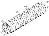
- FIG. 1is a perspective view of the inventive graft.
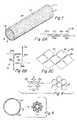
- FIG. 2Ais a fragmentary plan view depicting a first pattern of microperforations useful in the present invention.
- FIG. 2Bis a fragmentary plan view depicting a second pattern of microperforations useful in the present invention.
- FIG. 2Cis a fragmentary plan view depicting a third pattern of microperforations useful in the present invention.
- FIG. 2Dis a fragmentary plan view depicting a fourth pattern of microperforations useful in the present invention.
- FIG. 3Ais photomicrograph depicting the inventive graft having the first pattern of microperforation depicted in FIG. 2A in a geometrically undeformed state.
- FIG. 3Bis a photomicrograph of the inventive graft illustrated in FIG. 3A showing the microperforations in a geometrically deformed state.
- FIG. 4is a diagrammatic illustration depicting geometric deformation of the fourth pattern of microperforations in FIG. 2D .
- FIG. 5is a diagrammatic cross-sectional view illustration depicting the inventive graft assuming a folded condition suitable for endoluminal delivery.
- FIG. 6is a photographic illustration of the inventive graft used as a stent covering.
- FIG. 7is a photographic illustration of the inventive graft deformed approximately 180 degrees along its longitudinal axis illustrating the fabric-like quality of the graft.
- FIG. 8Ais a photographic illustration of the inventive graft circumferentially covering a braided expansion member and mounted on an expansion jig that exerts a compressive force along the longitudinal axis of the braided expansion member and which radially expands the braided expansion member.
- FIG. 8Bis a photographic illustration of the inventive graft radially exhibiting radial compliance under the influence of a radially expansive force.
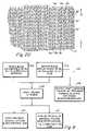
- FIG. 9is a flow diagram depicting alternate embodiments of making the inventive graft.
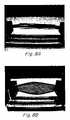
- FIG. 10Ais a histology slide, stained with hematoxylin and eosin, from a 28 day explanted swine carotid artery having the inventive graft implanted therein.
- FIG. 10Bis a histology slide, stained with hematoxylin and eosin, from a 28 day explanted swine carotid artery having the inventive graft implanted therein.
- the inventive microporous metallic implantable devicesmay assume a wide number of geometric configurations, including, for example, planar sheets, tubes or toroids.
- the accompanying figures and the following description of the inventionwill refer to tubular implantable graft members. Those skilled in the art, however, will understand that this is merely an exemplary geometric configuration and is not intended to limit the scope of the invention to tubular members or be limited in application to graft members.
- Graft 10consists generally of a body member 12 having a first surface 14 and a second surface 16 and a thickness 18 intermediate the first surface 14 and the second surface 16 .
- a plurality of microperforations 20is provided and pass through the thickness 18 of the body member 12 with interperforation regions 22 of the body member 12 between adjacent microperforation 20 .
- the plurality of microperforations 20each preferably have a geometric configuration that is susceptible of geometric change, such that the open surface area of each microperforation 20 may change under an externally applied load.
- Each of the plurality of microperforations 20 in the undeformed statepreferably has an open surface area less than about 2 mm 2 , with the total open surface area of the graft in the undeformed state being between 0.001 to 99%.
- the open surface area of the plurality of microperforations and the open surface area of the graftmay change considerably upon deformation of the plurality of microperforations 20 .
- Both the size of the microperforations 20 in the deformed and undeformed state and the total open area of the graft 12 in the deformed and undeformed statemay be selected in view of the following non-exclusive factors based on the graft application: 1) the desired compliance of the graft 10 , 2) the desired strength of the graft 10 , 3) desired stiffness of the graft 10 , 4) the desired degree of geometric enlargement of the microperforations 20 upon deformation and 5) in some cases, such as with vascular grafts, the desired delivery profile and post delivery profile.
- the plurality of microperforations 20is patterned in such a manner as to define deformation regions of the body member 12 .
- the thickness 18is between 0.1 ⁇ m and 75 ⁇ m, preferably between 1 ⁇ m and 50 ⁇ m.
- the graft 10has a thickness 18 which is thinner than the wall thickness of conventional non-metallic implantable grafts and that of conventional metal endoluminal stents.
- the plurality of microperforationsis patterned in a regular array forming a regular array of microperforations 20 in both the longitudinal and circumferential axes of the body member 12 .
- the pattern of microperforations 20will, hereinafter, be described with reference to a planar X-Y axes, which in a tubular member will correspond to the longitudinal or circumferential axes of the tubular member.
- X-axis or Y-axiswhen applied to a tubular member may be used such that the term “X-axis” may correspond to either the longitudinal axis or circumferential direction of the tubular member and the term “Y-axis” may refer to the corresponding circumferential direction or longitudinal axis or the tubular member.
- the particular intended use of the implantable member 12will be a consideration in the selection of the particular geometric pattern for the plurality of microperforations 20 .
- the implantable member 12has an intended use as a free-standing implantable endoluminal vascular graft, a large circumferential expansion ratio and longitudinal flexibility may be desirable.
- a particular geometry of the plurality of microperforations 20 that offers these propertieswill be selected.
- the plurality of microperforations 20also affect the material properties of the implantable member 10 .
- each microperforation 20may be altered so that each microperforation 20 exhibits stress-strain relief capabilities or the microperforations 20 may control whether geometric deformation of the microperforations 20 are plastic, elastic or superelastic deformation.
- both the geometry of the individual microperforations 20 , the orientation of the microperforations 20 relative to the X-Y axis of the implantable member 10 and the pattern of the microperforations 20may be selected to directly impart, affect or control the mechanical and material properties of the implantable member 10 .
- FIG. 2Aillustrates a first geometry for each of the plurality of microperforations 30 .
- each of the plurality of microperforations 30consist of generally elongated slots 32 a , 32 b .
- Each of the generally elongated slots 32 a , 32 bpreferably include terminal fillets 34 on opposing ends of each elongated slot 32 a , 32 b .
- the terminal fillets 34serve a strain relief function that aids in strain distribution through the interperforation regions 22 between adjacent slots 32 .
- FIG. 1illustrates a first geometry for each of the plurality of microperforations 30 .
- each of the plurality of microperforations 30consist of generally elongated slots 32 a , 32 b .
- Each of the generally elongated slots 32 a , 32 bpreferably include terminal fillets 34 on opposing ends of each elongated slot 32 a , 32 b .
- the terminal fillets 34serve
- 2Afurther illustrates a first geometric pattern for the plurality of microperforations 32 a , 32 b , wherein a first row of a plurality of microperforations 32 a is provided with adjacent microperforations 32 a being arrayed in end-to-end fashion along a common axis, and a second row of a plurality of microperforations 32 b is provided with adjacent microperforations 32 b being arrayed in end-to-end fashion along a common axis with one another and with the microperforations 32 a .
- the first row of microperforations 32 a and the second row of microperforations 32 bare offset or staggered from one another, with an end of a microperforation 32 a being laterally adjacent to an intermediate section of a microperforation 32 b , and an end of microperforation 32 b being laterally adjacent an intermediate section of a microperforation 32 a.
- the first geometry 30 of the plurality of microperforations 32 a , 32 b illustrated in FIG. 2Apermits a large deformation along an axis perpendicular to a longitudinal axis of the slots.
- the longitudinal axis of slots 32 a , 32 bis co-axial with the longitudinal axis of the implantable member 10
- deformation of the slots 32 a , 32 bwill permit circumferential compliance and/or expansion of the implantable member 10 .
- the slots 32 a , 32 bpermit longitudinal compliance, flexibility and expansion of the implantable member 10 .
- FIG. 2Billustrates a second geometry 40 for the plurality of microperforations 20 and consists of a plurality of microperforations 42 a , 44 b , again having a generally elongate slot-like configuration like those of the first geometry 30 .
- individual microperforations 42 a and 44 bare oriented orthogonal relative to one another.
- a first microperforation 42 ais oriented parallel to an X-axis of the implantable member 10
- a first microperforation 44 bis positioned adjacent to the first microperforation 44 a along the X-axis, but the first microperforation 44 b is oriented perpendicular to the X-axis of the implantable member 10 and parallel to the Y-axis of the implantable member 10 .
- each of the plurality of microperforations 42 a , 44 bmay include a terminal fillet 44 at opposing ends of the slot of each microperforation in order to serve a strain relief function and transmit strain to the interperforation region 22 between adjacent microperforations.
- This second geometry 40offers a balance in both compliance and degree of expansion in both the X and Y-axes of the implantable device 12
- each of the microperforations 32 a , 32 b , 42 a , 44 bhas a generally longitudinal slot configuration.
- Each of the generally longitudinal slotsmay be configured as a generally linear or curvilinear slot. In accordance with the preferred embodiments of the invention, however, it is preferred to employ generally linear slots.
- FIG. 2Cillustrates a third preferred geometry 50 for the plurality of microperforations.
- each of the plurality of microperforations 52has a generally trapezoidal or diamond-like shape with interperforation graft regions 56 between adjacent pairs of microperforations 52 .
- the third geometry 50may be achieved by geometrically deforming the first geometry 30 along an axis perpendicular to the longitudinal axis of the plurality of microperforations 32 a , 32 b .
- the first geometry 30may be achieved by deforming microperforations 52 in the third geometry 50 along either an X-axis or a Y-axis of the implantable member 10 .
- FIGS. 3A and 3Bare photomicrographs illustrating the inventive implantable device 12 having a plurality of microperforations formed as generally longitudinal slots 32 a , 32 b in accordance with the first geometry depicted in FIG. 2A .
- Each of the plurality of microperforationswere formed with an orientation parallel to the longitudinal axis of the implantable device 12 .
- the implantable device 12consists of a 6 mm inner diameter NiTi shape memory tubular graft member having a wall thickness of 5 ⁇ m.
- FIG. 3Adepicts the plurality of microperforations 32 a and 32 b in their undeformed state, while FIG.
- FIGS. 3A and 3Bdepicts the plurality of microperforations 32 a and 32 b in their geometrically deformed state under the influence of stain applied perpendicular to the longitudinal axis of the implantable graft 12 . It may be clearly understood that geometric deformation of the plurality of microperforations 32 a , 32 b permitted circumferential expansion of the inventive graft.
- the dimensions of each of the plurality of microperforations in their undeformed state depicted in FIGS. 3A and 3Bwas 430 ⁇ m in length, 50 ⁇ m width, with the terminal fillets having a 50 ⁇ m diameter.
- each of the plurality of microperforations 20have a generally tri-legged or Y-shaped configuration.
- the Y-shaped configuration of each of the plurality of microperforations 20has three co-planar radially projecting legs 31 a , 31 b , 31 e , each offset from the other by an angle of about 120 degrees thereby forming a generally Y-shape.
- Each of the three co-planar radially projecting legs 31 a , 31 b , 31 cmay be symmetrical or asymmetrical relative to one another.
- each of the plurality of microperforations 20has geometric symmetry.
- any number of different patternsmay be used without significantly departing from the inventive graft concept described in the present patent.
- each of the microperforations 20are capable of undergoing deformation upon application of a sufficient force.
- the graft 12may deform both circumferentially and longitudinally.
- each of the plurality of elongated slotsmay deform into opened microperforations which assume a generally rhomboidal shape.
- Y-shaped microperforations 20 shown in 4are capable of deformation into generally circular or oval open microperforations 21 .
- the deformation regions 22 between adjacent microperforations 20facilitate deformation of each of the plurality of microperforations 20 by deforming to accommodate opening of each of the plurality of microperforations 20 .
- the inventive graft 12may be folded to assume a smaller diametric profile for endoluminal delivery.
- the pattern of the plurality of microperforations 20may be fashioned to create a plurality of folding regions 23 , that constitute relatively weakened regions of the graft 12 , to permit folding the graft 12 along folding regions 23 .
- FIG. 6is a photographic illustration of the inventive microporous graft 12 circumferentially mounted onto an endoluminal stent 5 . It may be readily seen that the microporous graft 12 exhibits mechanical properties of high longitudinal flexibility and both radial and circumferential compliance.
- FIG. 7is a photographic illustration of the inventive microporous graft 12 mounted onto mandrel and flexed approximately 180 degrees along its longitudinal axis. Upon longitudinal flexion, the inventive graft 12 undergoes a high degree of folding with a plurality of circumferentially oriented folds 7 , characteristic of its fabric-like qualities.
- FIGS. 8A and 8Bare photographic reproductions illustrating the high degree of circumferential compliance of the inventive microporous graft 12 .
- a 6 mm microporous graft having a 5 ⁇ m wall thicknesswas mounted concentrically over a braided pseudostent.
- An axial forcewas applied along the longitudinal axis of the braided pseudostent causing the pseudostent to radially expand and exert a circumferentially expansive force to the inventive graft 12 .
- the plurality of micropores in the inventive graft 12geometrically deform thereby permitting circumferential expansion of the graft 12 .
- one embodiment of the present inventionprovides a new metallic and/or pseudometallic implantable graft that is biocompatible, geometrically changeable either by folding and unfolding or by application of a plastically, elastically or superelastically deforming force, and capable of endoluminal delivery with a suitably small delivery profile.
- Suitable metal materials to fabricate the inventive graftare chosen for their biocompatibility, mechanical properties, i.e., tensile strength, yield strength, and their ease of fabrication.
- the compliant nature of the inventive graft materialmay be employed to form the graft into complex shapes by deforming the inventive graft over a mandrel or fixture of the appropriate design. Plastic deformation and shape setting heat treatments may be employed to ensure the inventive implantable members 10 retain a desired conformation.
- the graftis fabricated of vacuum deposited metallic and/or pseudometallic films.
- the fabrication method 100 of the present inventionis illustrated.
- a precursor blank of a conventionally fabricated biocompatible metal or pseudometallic materialmay be employed at step 102 .
- a precursor blank of a vacuum deposited metal or pseudometallic filmmay be employed at step 104 .
- the precursor blank material obtained either from step 102 or step 104is then preferably masked at step 108 leaving exposed only those regions defining the plurality of microperforations.
- the exposed regions from step 108are then subjected to removal either by etching at step 110 , such as by wet or dry chemical etching processing, with the etchant being selected based upon the material of the precursor blank, or by machining at step 112 , such as by laser ablation or EDM.
- etchingsuch as by wet or dry chemical etching processing
- machiningsuch as by laser ablation or EDM.
- a pattern mask corresponding to the plurality of microperforationsmay be interposed at step 106 between the target and the source and the metal or pseudometal deposited through the pattern mask to form the patterned microperforations.
- plural film layersmaybe deposited to form a multilayer film structure of the film prior to or concurrently with forming the plurality of microperforations.
- the present inventionprovides a new metallic and/or pseudometallic implantable graft that is biocompatible, compliant, geometrically changeable either by folding and unfolding or by application of a plastically, elastically or superelastically deforming force, and, in some cases, capable of endoluminal delivery with a suitably small delivery profile and suitably low post-delivery profile.
- Suitable metal materials to fabricate the inventive graftare chosen for their biocompatibility, mechanical properties, i.e., tensile strength, yield strength, and in the case where vapor deposition is deployed, their ease of deposition include, without limitation, the following: titanium, vanadium, aluminum, nickel, tantalum, zirconium, chromium, silver, gold, silicon, magnesium, niobium, scandium, platinum, cobalt, palladium, manganese, molybdenum and alloys thereof, such as zirconium-titanium-tantalum alloys, nitinol, and stainless steel.
- pseudometallic materials potentially useful with the present inventioninclude, for example, composite materials and ceramics.
- the present inventionalso provides a method of making the inventive expandable metallic graft by vacuum deposition of a graft-forming metal or pseudometal and formation of the microperforations either by removing sections of deposited material, such as by etching, EDM, ablation, or other similar methods, or by interposing a pattern mask, corresponding to the microperforations, between the target and the source during deposition processing.
- a pre-existing metal and/or pseudometallic film manufactured by conventional non-vacuum deposition methodologies, such as wrought hypotube or sheet,may be obtained, and the microperforations formed in the pre-existing metal and/or pseudometallic film by removing sections of the film, such as by etching, EDM, ablation, or other similar methods.
- an advantage of employing multilayer film structures to form the inventive graftis that differential functionalities may be imparted in the discrete layers.
- a radiopaque materialsuch as tantalum may form one layer of a structure while other layers are chosen to provide the graft with its desired mechanical and structural properties.
- a cylindrical deoxygenated copper substrateis provided.
- the substrateis mechanically and/or electropolished to provide a substantially uniform surface topography for accommodating metal deposition thereupon.
- a cylindrical hollow cathode magnetron sputtering deposition devicewas employed, in which the cathode was on the outside and the substrate was positioned along the longitudinal axis of the cathode.
- a cylindrical targetconsisting either of a nickel-titanium alloy having an atomic ratio of nickel to titanium of about 50-50% and which can be adjusted by spot welding nickel or titanium wires to the target, or a nickel cylinder having a plurality of titanium strips spot welded to the inner surface of the nickel cylinder, or a titanium cylinder having a plurality of nickel strips spot welded to the inner surface of the titanium cylinder is provided. It is known in the sputter deposition arts to cool a target within the deposition chamber by maintaining a thermal contact between the target and a cooling jacket within the cathode. In accordance with the present invention, it has been found useful to reduce the thermal cooling by thermally insulating the target from the cooling jacket within the cathode while still providing electrical contact to it.
- the targetBy insulating the target from the cooling jacket, the target is allowed to become hot within the reaction chamber.
- Two methods of thermally isolating the cylindrical target from the cooling jacket of the cathodewere employed.
- a plurality of wires having a diameter of 0.0381 mmwere spot welded around the outer circumference of the target to provide an equivalent spacing between the target and the cathode cooling jacket.
- a tubular ceramic insulating sleevewas interposed between the outer circumference of the target and the cathode cooling jacket.
- the deposition chamberwas evacuated to a pressure less than or about 2-5 ⁇ 10 ⁇ 7 Torr and pre-cleaning of the substrate is conducted under vacuum.
- substrate temperatureis preferably maintained within the range of 300 and 700 degrees Centigrade. It is preferable to apply a negative bias voltage between 0 and ⁇ 1000 volts to the substrate, and preferably between ⁇ 50 and ⁇ 150 volts, which is sufficient to cause energetic species arriving at the surface of the substrate.
- the gas pressureis maintained between 0.1 and 40 mTorr but preferably between 1 and 20 mTorr.
- Sputteringpreferably occurs in the presence of an Argon atmosphere.
- the argon gasmust be of high purity and special pumps may be employed to reduce oxygen partial pressure.
- Deposition timeswill vary depending upon the desired thickness of the deposited tubular film.
- the plurality of microperforationsare formed in the tube by removing regions of the deposited film by etching, such as chemical etching, ablation, such as by excimer laser or by electric discharge machining (EDM), or the like.
- etchingsuch as chemical etching
- ablationsuch as by excimer laser or by electric discharge machining (EDM), or the like.
- EDMelectric discharge machining
- FIG. 10Ahistology of the explanted samples revealed complete endothelialization around the graft 12 , negligible neointimal proliferation with the absence of trauma to the internal elastic lamina.
- FIG. 10Bis a sample indicating cross-talk between the arterial superficial and deep layers with the transmural formation of small capillaries.
Landscapes
- Health & Medical Sciences (AREA)
- Engineering & Computer Science (AREA)
- Biomedical Technology (AREA)
- Heart & Thoracic Surgery (AREA)
- Public Health (AREA)
- Transplantation (AREA)
- Cardiology (AREA)
- Veterinary Medicine (AREA)
- Oral & Maxillofacial Surgery (AREA)
- Vascular Medicine (AREA)
- Life Sciences & Earth Sciences (AREA)
- Animal Behavior & Ethology (AREA)
- General Health & Medical Sciences (AREA)
- Physics & Mathematics (AREA)
- Optics & Photonics (AREA)
- Gastroenterology & Hepatology (AREA)
- Pulmonology (AREA)
- Prostheses (AREA)
- Materials For Medical Uses (AREA)
Abstract
Description
Claims (18)
Priority Applications (12)
| Application Number | Priority Date | Filing Date | Title |
|---|---|---|---|
| US10/135,316US7300457B2 (en) | 1999-11-19 | 2002-04-29 | Self-supporting metallic implantable grafts, compliant implantable medical devices and methods of making same |
| DE60239878TDE60239878D1 (en) | 2001-08-07 | 2002-08-01 | SELF SUPPORTING IMPLANTABLE METAL PROSTHESES |
| PCT/US2002/024719WO2003013337A2 (en) | 2001-08-07 | 2002-08-01 | Medical grafts having plurality of microperforations |
| EP02756942.5AEP1420717B2 (en) | 2001-08-07 | 2002-08-01 | Self-supporting metallic implantable grafts |
| AT02756942TATE506910T1 (en) | 2001-08-07 | 2002-08-01 | SELF-SUPPORTING IMPLANTABLE METAL DENTURES |
| EP10185229.1AEP2298249B1 (en) | 2001-08-07 | 2002-08-01 | Self-supporting metallic implantable grafts |
| AU2002321909AAU2002321909B2 (en) | 2001-08-07 | 2002-08-01 | Medical grafts having plurality of microperforations |
| JP2003518356AJP4934269B2 (en) | 2001-08-07 | 2002-08-01 | Medical graft with multiple micropores |
| CA002456697ACA2456697C (en) | 2001-08-07 | 2002-08-01 | Self-supporting metallic implantable grafts, compliant implantable medical devices and methods of making same |
| US12/686,350US9284637B2 (en) | 1999-11-19 | 2010-01-12 | Implantable graft and methods of making same |
| US13/673,168US9132001B2 (en) | 1999-11-19 | 2012-11-09 | Metallic implantable grafts and method of making same |
| US14/852,371US9668852B2 (en) | 1999-11-19 | 2015-09-11 | Metallic implantable grafts and method of making same |
Applications Claiming Priority (5)
| Application Number | Priority Date | Filing Date | Title |
|---|---|---|---|
| US09/443,929US6379383B1 (en) | 1999-11-19 | 1999-11-19 | Endoluminal device exhibiting improved endothelialization and method of manufacture thereof |
| US09/532,164US6537310B1 (en) | 1999-11-19 | 2000-03-20 | Endoluminal implantable devices and method of making same |
| US30279701P | 2001-07-03 | 2001-07-03 | |
| US31061701P | 2001-08-07 | 2001-08-07 | |
| US10/135,316US7300457B2 (en) | 1999-11-19 | 2002-04-29 | Self-supporting metallic implantable grafts, compliant implantable medical devices and methods of making same |
Related Parent Applications (2)
| Application Number | Title | Priority Date | Filing Date |
|---|---|---|---|
| US09/443,929Continuation-In-PartUS6379383B1 (en) | 1999-11-19 | 1999-11-19 | Endoluminal device exhibiting improved endothelialization and method of manufacture thereof |
| US09/532,164Continuation-In-PartUS6537310B1 (en) | 1999-11-19 | 2000-03-20 | Endoluminal implantable devices and method of making same |
Publications (2)
| Publication Number | Publication Date |
|---|---|
| US20070250156A1 US20070250156A1 (en) | 2007-10-25 |
| US7300457B2true US7300457B2 (en) | 2007-11-27 |
Family
ID=26833204
Family Applications (1)
| Application Number | Title | Priority Date | Filing Date |
|---|---|---|---|
| US10/135,316Expired - LifetimeUS7300457B2 (en) | 1999-11-19 | 2002-04-29 | Self-supporting metallic implantable grafts, compliant implantable medical devices and methods of making same |
Country Status (8)
| Country | Link |
|---|---|
| US (1) | US7300457B2 (en) |
| EP (2) | EP1420717B2 (en) |
| JP (1) | JP4934269B2 (en) |
| AT (1) | ATE506910T1 (en) |
| AU (1) | AU2002321909B2 (en) |
| CA (1) | CA2456697C (en) |
| DE (1) | DE60239878D1 (en) |
| WO (1) | WO2003013337A2 (en) |
Cited By (81)
| Publication number | Priority date | Publication date | Assignee | Title |
|---|---|---|---|---|
| US20060069428A1 (en)* | 2004-09-20 | 2006-03-30 | Feller Frederick Iii | Thin film medical device and delivery system |
| US20070050017A1 (en)* | 2005-08-31 | 2007-03-01 | Sims Daniel D | Covered stent with proximal and distal attachment, delivery catheter, and method of making same |
| US20080097495A1 (en)* | 2004-09-17 | 2008-04-24 | Feller Lll Frederick R | Thin Film Metallic Device for Plugging Aneurysms or Vessels |
| US7611535B2 (en) | 2001-09-07 | 2009-11-03 | Medtronic, Inc. | Fixation band for affixing a prosthetic heart valve to tissue |
| US7682390B2 (en) | 2001-07-31 | 2010-03-23 | Medtronic, Inc. | Assembly for setting a valve prosthesis in a corporeal duct |
| US20100106235A1 (en)* | 2008-10-27 | 2010-04-29 | Aga Medical Corporation | Multi-layer device with gap for treating a target site and associated method |
| US7758606B2 (en) | 2000-06-30 | 2010-07-20 | Medtronic, Inc. | Intravascular filter with debris entrapment mechanism |
| US7780726B2 (en) | 2001-07-04 | 2010-08-24 | Medtronic, Inc. | Assembly for placing a prosthetic valve in a duct in the body |
| US7871436B2 (en) | 2007-02-16 | 2011-01-18 | Medtronic, Inc. | Replacement prosthetic heart valves and methods of implantation |
| US7892281B2 (en) | 1999-11-17 | 2011-02-22 | Medtronic Corevalve Llc | Prosthetic valve for transluminal delivery |
| US7914569B2 (en) | 2005-05-13 | 2011-03-29 | Medtronics Corevalve Llc | Heart valve prosthesis and methods of manufacture and use |
| US7972378B2 (en) | 2008-01-24 | 2011-07-05 | Medtronic, Inc. | Stents for prosthetic heart valves |
| US8016877B2 (en) | 1999-11-17 | 2011-09-13 | Medtronic Corevalve Llc | Prosthetic valve for transluminal delivery |
| US8052750B2 (en) | 2006-09-19 | 2011-11-08 | Medtronic Ventor Technologies Ltd | Valve prosthesis fixation techniques using sandwiching |
| US8070801B2 (en) | 2001-06-29 | 2011-12-06 | Medtronic, Inc. | Method and apparatus for resecting and replacing an aortic valve |
| US8075615B2 (en) | 2006-03-28 | 2011-12-13 | Medtronic, Inc. | Prosthetic cardiac valve formed from pericardium material and methods of making same |
| US8109996B2 (en) | 2004-03-03 | 2012-02-07 | Sorin Biomedica Cardio, S.R.L. | Minimally-invasive cardiac-valve prosthesis |
| US8137398B2 (en) | 2008-10-13 | 2012-03-20 | Medtronic Ventor Technologies Ltd | Prosthetic valve having tapered tip when compressed for delivery |
| US8157852B2 (en) | 2008-01-24 | 2012-04-17 | Medtronic, Inc. | Delivery systems and methods of implantation for prosthetic heart valves |
| US8241274B2 (en) | 2000-01-19 | 2012-08-14 | Medtronic, Inc. | Method for guiding a medical device |
| US8313525B2 (en) | 2008-03-18 | 2012-11-20 | Medtronic Ventor Technologies, Ltd. | Valve suturing and implantation procedures |
| US8312825B2 (en) | 2008-04-23 | 2012-11-20 | Medtronic, Inc. | Methods and apparatuses for assembly of a pericardial prosthetic heart valve |
| US8430927B2 (en) | 2008-04-08 | 2013-04-30 | Medtronic, Inc. | Multiple orifice implantable heart valve and methods of implantation |
| US8506620B2 (en) | 2005-09-26 | 2013-08-13 | Medtronic, Inc. | Prosthetic cardiac and venous valves |
| US8512397B2 (en) | 2009-04-27 | 2013-08-20 | Sorin Group Italia S.R.L. | Prosthetic vascular conduit |
| US8540768B2 (en) | 2005-02-10 | 2013-09-24 | Sorin Group Italia S.R.L. | Cardiac valve prosthesis |
| US8562672B2 (en) | 2004-11-19 | 2013-10-22 | Medtronic, Inc. | Apparatus for treatment of cardiac valves and method of its manufacture |
| US8579966B2 (en) | 1999-11-17 | 2013-11-12 | Medtronic Corevalve Llc | Prosthetic valve for transluminal delivery |
| US8591570B2 (en) | 2004-09-07 | 2013-11-26 | Medtronic, Inc. | Prosthetic heart valve for replacing previously implanted heart valve |
| US8613765B2 (en) | 2008-02-28 | 2013-12-24 | Medtronic, Inc. | Prosthetic heart valve systems |
| US8623077B2 (en) | 2001-06-29 | 2014-01-07 | Medtronic, Inc. | Apparatus for replacing a cardiac valve |
| US8628566B2 (en) | 2008-01-24 | 2014-01-14 | Medtronic, Inc. | Stents for prosthetic heart valves |
| US8652204B2 (en) | 2010-04-01 | 2014-02-18 | Medtronic, Inc. | Transcatheter valve with torsion spring fixation and related systems and methods |
| US8685084B2 (en) | 2011-12-29 | 2014-04-01 | Sorin Group Italia S.R.L. | Prosthetic vascular conduit and assembly method |
| US8696689B2 (en) | 2008-03-18 | 2014-04-15 | Medtronic Ventor Technologies Ltd. | Medical suturing device and method for use thereof |
| US8696743B2 (en) | 2008-04-23 | 2014-04-15 | Medtronic, Inc. | Tissue attachment devices and methods for prosthetic heart valves |
| US8721714B2 (en) | 2008-09-17 | 2014-05-13 | Medtronic Corevalve Llc | Delivery system for deployment of medical devices |
| US8747459B2 (en) | 2006-12-06 | 2014-06-10 | Medtronic Corevalve Llc | System and method for transapical delivery of an annulus anchored self-expanding valve |
| US8747458B2 (en) | 2007-08-20 | 2014-06-10 | Medtronic Ventor Technologies Ltd. | Stent loading tool and method for use thereof |
| US8771302B2 (en) | 2001-06-29 | 2014-07-08 | Medtronic, Inc. | Method and apparatus for resecting and replacing an aortic valve |
| US8784478B2 (en) | 2006-10-16 | 2014-07-22 | Medtronic Corevalve, Inc. | Transapical delivery system with ventruculo-arterial overlfow bypass |
| US8808369B2 (en) | 2009-10-05 | 2014-08-19 | Mayo Foundation For Medical Education And Research | Minimally invasive aortic valve replacement |
| US8834563B2 (en) | 2008-12-23 | 2014-09-16 | Sorin Group Italia S.R.L. | Expandable prosthetic valve having anchoring appendages |
| US8834564B2 (en) | 2006-09-19 | 2014-09-16 | Medtronic, Inc. | Sinus-engaging valve fixation member |
| US8840661B2 (en) | 2008-05-16 | 2014-09-23 | Sorin Group Italia S.R.L. | Atraumatic prosthetic heart valve prosthesis |
| US8910363B2 (en)* | 1999-11-19 | 2014-12-16 | Advanced Bio Prosthetic Surfaces, Ltd. | Compliant implantable medical devices and methods of making same |
| US8951280B2 (en) | 2000-11-09 | 2015-02-10 | Medtronic, Inc. | Cardiac valve procedure methods and devices |
| US8986361B2 (en) | 2008-10-17 | 2015-03-24 | Medtronic Corevalve, Inc. | Delivery system for deployment of medical devices |
| US8998981B2 (en) | 2008-09-15 | 2015-04-07 | Medtronic, Inc. | Prosthetic heart valve having identifiers for aiding in radiographic positioning |
| US9089422B2 (en) | 2008-01-24 | 2015-07-28 | Medtronic, Inc. | Markers for prosthetic heart valves |
| US9149358B2 (en) | 2008-01-24 | 2015-10-06 | Medtronic, Inc. | Delivery systems for prosthetic heart valves |
| US9161836B2 (en) | 2011-02-14 | 2015-10-20 | Sorin Group Italia S.R.L. | Sutureless anchoring device for cardiac valve prostheses |
| US9226826B2 (en) | 2010-02-24 | 2016-01-05 | Medtronic, Inc. | Transcatheter valve structure and methods for valve delivery |
| US9237886B2 (en) | 2007-04-20 | 2016-01-19 | Medtronic, Inc. | Implant for treatment of a heart valve, in particular a mitral valve, material including such an implant, and material for insertion thereof |
| US9248017B2 (en) | 2010-05-21 | 2016-02-02 | Sorin Group Italia S.R.L. | Support device for valve prostheses and corresponding kit |
| US9289289B2 (en) | 2011-02-14 | 2016-03-22 | Sorin Group Italia S.R.L. | Sutureless anchoring device for cardiac valve prostheses |
| US9393115B2 (en) | 2008-01-24 | 2016-07-19 | Medtronic, Inc. | Delivery systems and methods of implantation for prosthetic heart valves |
| US20170028109A1 (en)* | 2002-09-26 | 2017-02-02 | Palmaz Scientific, Inc. | Implantable materials having engineered surfaces and method of making same |
| US9579194B2 (en) | 2003-10-06 | 2017-02-28 | Medtronic ATS Medical, Inc. | Anchoring structure with concave landing zone |
| US9629718B2 (en) | 2013-05-03 | 2017-04-25 | Medtronic, Inc. | Valve delivery tool |
| US9775704B2 (en) | 2004-04-23 | 2017-10-03 | Medtronic3F Therapeutics, Inc. | Implantable valve prosthesis |
| US9848981B2 (en) | 2007-10-12 | 2017-12-26 | Mayo Foundation For Medical Education And Research | Expandable valve prosthesis with sealing mechanism |
| US9918833B2 (en) | 2010-09-01 | 2018-03-20 | Medtronic Vascular Galway | Prosthetic valve support structure |
| US10485976B2 (en) | 1998-04-30 | 2019-11-26 | Medtronic, Inc. | Intracardiovascular access (ICVA™) system |
| US10856970B2 (en) | 2007-10-10 | 2020-12-08 | Medtronic Ventor Technologies Ltd. | Prosthetic heart valve for transfemoral delivery |
| US10993805B2 (en) | 2008-02-26 | 2021-05-04 | Jenavalve Technology, Inc. | Stent for the positioning and anchoring of a valvular prosthesis in an implantation site in the heart of a patient |
| US11065138B2 (en) | 2016-05-13 | 2021-07-20 | Jenavalve Technology, Inc. | Heart valve prosthesis delivery system and method for delivery of heart valve prosthesis with introducer sheath and loading system |
| US11185405B2 (en) | 2013-08-30 | 2021-11-30 | Jenavalve Technology, Inc. | Radially collapsible frame for a prosthetic valve and method for manufacturing such a frame |
| US11197754B2 (en) | 2017-01-27 | 2021-12-14 | Jenavalve Technology, Inc. | Heart valve mimicry |
| US11304800B2 (en) | 2006-09-19 | 2022-04-19 | Medtronic Ventor Technologies Ltd. | Sinus-engaging valve fixation member |
| US11337800B2 (en) | 2015-05-01 | 2022-05-24 | Jenavalve Technology, Inc. | Device and method with reduced pacemaker rate in heart valve replacement |
| US11357624B2 (en) | 2007-04-13 | 2022-06-14 | Jenavalve Technology, Inc. | Medical device for treating a heart valve insufficiency |
| US11504231B2 (en) | 2018-05-23 | 2022-11-22 | Corcym S.R.L. | Cardiac valve prosthesis |
| US11517431B2 (en) | 2005-01-20 | 2022-12-06 | Jenavalve Technology, Inc. | Catheter system for implantation of prosthetic heart valves |
| US11564794B2 (en) | 2008-02-26 | 2023-01-31 | Jenavalve Technology, Inc. | Stent for the positioning and anchoring of a valvular prosthesis in an implantation site in the heart of a patient |
| US11589981B2 (en) | 2010-05-25 | 2023-02-28 | Jenavalve Technology, Inc. | Prosthetic heart valve and transcatheter delivered endoprosthesis comprising a prosthetic heart valve and a stent |
| US12121461B2 (en) | 2015-03-20 | 2024-10-22 | Jenavalve Technology, Inc. | Heart valve prosthesis delivery system and method for delivery of heart valve prosthesis with introducer sheath |
| US12171658B2 (en) | 2022-11-09 | 2024-12-24 | Jenavalve Technology, Inc. | Catheter system for sequential deployment of an expandable implant |
| EP4545936A2 (en) | 2016-03-17 | 2025-04-30 | Becton, Dickinson and Company | Cell sorting using a high throughput fluorescence flow cytometer |
| US12318289B2 (en) | 2018-05-23 | 2025-06-03 | Corcym S.R.L. | Device for the in-situ delivery of heart valve prosthesis |
| US12414854B2 (en) | 2010-05-20 | 2025-09-16 | Jenavalve Technology, Inc. | Catheter system for introducing an expandable stent into the body of a patient |
Families Citing this family (52)
| Publication number | Priority date | Publication date | Assignee | Title |
|---|---|---|---|---|
| US7736687B2 (en) | 2006-01-31 | 2010-06-15 | Advance Bio Prosthetic Surfaces, Ltd. | Methods of making medical devices |
| US6936066B2 (en) | 1999-11-19 | 2005-08-30 | Advanced Bio Prosthetic Surfaces, Ltd. | Complaint implantable medical devices and methods of making same |
| US7300457B2 (en)* | 1999-11-19 | 2007-11-27 | Advanced Bio Prosthetic Surfaces, Ltd. | Self-supporting metallic implantable grafts, compliant implantable medical devices and methods of making same |
| US9566148B2 (en) | 2000-05-12 | 2017-02-14 | Vactronix Scientific, Inc. | Self-supporting laminated films, structural materials and medical devices manufactured therefrom and methods of making same |
| WO2003002243A2 (en) | 2001-06-27 | 2003-01-09 | Remon Medical Technologies Ltd. | Method and device for electrochemical formation of therapeutic species in vivo |
| US8268340B2 (en) | 2002-09-26 | 2012-09-18 | Advanced Bio Prosthetic Surfaces, Ltd. | Implantable materials having engineered surfaces and method of making same |
| AU2003270817B2 (en) | 2002-09-26 | 2009-09-17 | Vactronix Scientific, Llc | High strength vacuum deposited nitionol alloy films, medical thin film graft materials and method of making same |
| US20040260315A1 (en)* | 2003-06-17 | 2004-12-23 | Dell Jeffrey R. | Expandable tissue support member and method of forming the support member |
| NZ527025A (en) | 2003-07-16 | 2007-01-26 | David Peter Shaw | Prosthetic valves for medical application |
| US7488343B2 (en)* | 2003-09-16 | 2009-02-10 | Boston Scientific Scimed, Inc. | Medical devices |
| AU2004277970A1 (en) | 2003-09-30 | 2005-04-14 | Merit Medical Systems, Inc. | Active stent |
| US20070106374A1 (en)* | 2004-01-22 | 2007-05-10 | Isoflux, Inc. | Radiopaque coating for biomedical devices |
| US8998973B2 (en) | 2004-03-02 | 2015-04-07 | Boston Scientific Scimed, Inc. | Medical devices including metallic films |
| US8992592B2 (en) | 2004-12-29 | 2015-03-31 | Boston Scientific Scimed, Inc. | Medical devices including metallic films |
| US8591568B2 (en) | 2004-03-02 | 2013-11-26 | Boston Scientific Scimed, Inc. | Medical devices including metallic films and methods for making same |
| US8632580B2 (en) | 2004-12-29 | 2014-01-21 | Boston Scientific Scimed, Inc. | Flexible medical devices including metallic films |
| CA2558128C (en)* | 2004-03-02 | 2013-01-08 | Boston Scientific Scimed, Inc. | Medical devices including metallic films and polymer layers |
| US7901447B2 (en) | 2004-12-29 | 2011-03-08 | Boston Scientific Scimed, Inc. | Medical devices including a metallic film and at least one filament |
| US8894824B2 (en)* | 2004-06-28 | 2014-11-25 | Isoflux, Inc. | Porous coatings for biomedical implants |
| EP2468348B1 (en)* | 2004-09-17 | 2016-10-26 | Codman & Shurtleff, Inc. | Thin film metallic devices for plugging aneurysms or vessels |
| US20080004653A1 (en)* | 2004-09-17 | 2008-01-03 | Sherman Darren R | Thin Film Devices for Occlusion of a Vessel |
| WO2006071244A1 (en)* | 2004-12-29 | 2006-07-06 | Boston Scientific Limited | Medical devices including metallic films and methods for making the same |
| WO2006071243A1 (en)* | 2004-12-29 | 2006-07-06 | Boston Scientific Limited | Medical devices including metallic films and methods for making same |
| WO2006071242A1 (en)* | 2004-12-29 | 2006-07-06 | Boston Scientific Limited | Medical devices including metallic films and methods for making same |
| US7854760B2 (en) | 2005-05-16 | 2010-12-21 | Boston Scientific Scimed, Inc. | Medical devices including metallic films |
| US8840660B2 (en) | 2006-01-05 | 2014-09-23 | Boston Scientific Scimed, Inc. | Bioerodible endoprostheses and methods of making the same |
| US8089029B2 (en) | 2006-02-01 | 2012-01-03 | Boston Scientific Scimed, Inc. | Bioabsorbable metal medical device and method of manufacture |
| US8048150B2 (en) | 2006-04-12 | 2011-11-01 | Boston Scientific Scimed, Inc. | Endoprosthesis having a fiber meshwork disposed thereon |
| EP2054537A2 (en) | 2006-08-02 | 2009-05-06 | Boston Scientific Scimed, Inc. | Endoprosthesis with three-dimensional disintegration control |
| ES2357661T3 (en)* | 2006-09-15 | 2011-04-28 | Boston Scientific Scimed, Inc. | BIOEROSIONABLE ENDOPROOTHESIS WITH BIOESTABLE INORGANIC LAYERS. |
| WO2008034066A1 (en) | 2006-09-15 | 2008-03-20 | Boston Scientific Limited | Bioerodible endoprostheses and methods of making the same |
| WO2008034047A2 (en)* | 2006-09-15 | 2008-03-20 | Boston Scientific Limited | Endoprosthesis with adjustable surface features |
| JP2010503489A (en) | 2006-09-15 | 2010-02-04 | ボストン サイエンティフィック リミテッド | Biodegradable endoprosthesis and method for producing the same |
| EP2959925B1 (en) | 2006-09-15 | 2018-08-29 | Boston Scientific Limited | Medical devices and methods of making the same |
| WO2008036548A2 (en) | 2006-09-18 | 2008-03-27 | Boston Scientific Limited | Endoprostheses |
| ES2506144T3 (en) | 2006-12-28 | 2014-10-13 | Boston Scientific Limited | Bioerodible endoprosthesis and their manufacturing procedure |
| US8052745B2 (en) | 2007-09-13 | 2011-11-08 | Boston Scientific Scimed, Inc. | Endoprosthesis |
| US8926688B2 (en)* | 2008-01-11 | 2015-01-06 | W. L. Gore & Assoc. Inc. | Stent having adjacent elements connected by flexible webs |
| RU2357928C1 (en)* | 2008-03-11 | 2009-06-10 | Юрий Олегович Бобылев | Method for making microperforations on elastic jacket and device for its realisation |
| US7998192B2 (en) | 2008-05-09 | 2011-08-16 | Boston Scientific Scimed, Inc. | Endoprostheses |
| US8236046B2 (en) | 2008-06-10 | 2012-08-07 | Boston Scientific Scimed, Inc. | Bioerodible endoprosthesis |
| US7985252B2 (en) | 2008-07-30 | 2011-07-26 | Boston Scientific Scimed, Inc. | Bioerodible endoprosthesis |
| US8382824B2 (en) | 2008-10-03 | 2013-02-26 | Boston Scientific Scimed, Inc. | Medical implant having NANO-crystal grains with barrier layers of metal nitrides or fluorides |
| EP2403546A2 (en) | 2009-03-02 | 2012-01-11 | Boston Scientific Scimed, Inc. | Self-buffering medical implants |
| WO2011104875A1 (en)* | 2010-02-26 | 2011-09-01 | 株式会社ティー・アンド・アイ | Instrument for treating soft tissue |
| US8668732B2 (en) | 2010-03-23 | 2014-03-11 | Boston Scientific Scimed, Inc. | Surface treated bioerodible metal endoprostheses |
| US10299948B2 (en) | 2014-11-26 | 2019-05-28 | W. L. Gore & Associates, Inc. | Balloon expandable endoprosthesis |
| JP6050444B2 (en)* | 2015-07-31 | 2016-12-21 | 京セラメディカル株式会社 | Bone guided regeneration support |
| US10568752B2 (en) | 2016-05-25 | 2020-02-25 | W. L. Gore & Associates, Inc. | Controlled endoprosthesis balloon expansion |
| JP6306132B2 (en)* | 2016-11-24 | 2018-04-04 | 京セラ株式会社 | Bone guided regeneration support |
| CN106730373B (en)* | 2017-02-06 | 2023-12-08 | 中国人民解放军总医院 | Cobalt zirconium molybdenum alloy mark |
| US11576797B2 (en)* | 2017-10-13 | 2023-02-14 | The Secant Group, Llc | Bored hollow lumen |
Citations (140)
| Publication number | Priority date | Publication date | Assignee | Title |
|---|---|---|---|---|
| US4073999A (en) | 1975-05-09 | 1978-02-14 | Minnesota Mining And Manufacturing Company | Porous ceramic or metallic coatings and articles |
| US4510182A (en) | 1981-08-27 | 1985-04-09 | Ruhrchemie Aktiengesellschaft | Method for the production of homogeneous coatings of two or more metals and/or metal compounds |
| JPS6188135A (en) | 1984-10-05 | 1986-05-06 | Nec Corp | Production of semiconductor biosensor |
| US4657544A (en) | 1984-04-18 | 1987-04-14 | Cordis Corporation | Cardiovascular graft and method of forming same |
| US4751099A (en) | 1985-12-28 | 1988-06-14 | National Aerospace Laboratories of Science and Technology Agency | Method of producing a functionally gradient material |
| US4846834A (en) | 1986-05-27 | 1989-07-11 | Clemson University | Method for promoting tissue adhesion to soft tissue implants |
| US5049251A (en) | 1988-06-10 | 1991-09-17 | Fujitsu Limited | Sputtering method for fabricating thin film |
| US5061914A (en) | 1989-06-27 | 1991-10-29 | Tini Alloy Company | Shape-memory alloy micro-actuator |
| US5078736A (en) | 1990-05-04 | 1992-01-07 | Interventional Thermodynamics, Inc. | Method and apparatus for maintaining patency in the body passages |
| US5084151A (en) | 1985-11-26 | 1992-01-28 | Sorin Biomedica S.P.A. | Method and apparatus for forming prosthetic device having a biocompatible carbon film thereon |
| US5133845A (en) | 1986-12-12 | 1992-07-28 | Sorin Biomedica, S.P.A. | Method for making prosthesis of polymeric material coated with biocompatible carbon |
| US5207709A (en) | 1991-11-13 | 1993-05-04 | Picha George J | Implant with textured surface |
| US5242710A (en) | 1990-06-25 | 1993-09-07 | Lanxide Technology Company, Lp | Methods for making self-supporting composite bodies and articles produced thereby |
| US5277933A (en) | 1990-06-25 | 1994-01-11 | Lanxide Technology Company, Lp | Method for forming a self-supporting body using vapor-phase parent metals and solid oxidants |
| EP0274846B1 (en) | 1986-12-09 | 1994-02-09 | Boston Scientific Corporation | Apparatus for treating hypertrophy of the prostate gland |
| US5370684A (en) | 1986-12-12 | 1994-12-06 | Sorin Biomedica S.P.A. | Prosthesis of polymeric material coated with biocompatible carbon |
| US5387247A (en) | 1983-10-25 | 1995-02-07 | Sorin Biomedia S.P.A. | Prosthetic device having a biocompatible carbon film thereon and a method of and apparatus for forming such device |
| US5421955A (en) | 1991-10-28 | 1995-06-06 | Advanced Cardiovascular Systems, Inc. | Expandable stents and method for making same |
| US5455100A (en) | 1991-01-30 | 1995-10-03 | Interpore International | Porous articles and methods for producing same |
| US5477864A (en) | 1989-12-21 | 1995-12-26 | Smith & Nephew Richards, Inc. | Cardiovascular guidewire of enhanced biocompatibility |
| US5540820A (en) | 1990-11-30 | 1996-07-30 | Hitachi, Ltd. | Thin film forming method |
| US5545210A (en) | 1994-09-22 | 1996-08-13 | Advanced Coronary Technology, Inc. | Method of implanting a permanent shape memory alloy stent |
| US5569295A (en) | 1993-12-28 | 1996-10-29 | Advanced Cardiovascular Systems, Inc. | Expandable stents and method for making same |
| US5571173A (en)* | 1990-06-11 | 1996-11-05 | Parodi; Juan C. | Graft to repair a body passageway |
| US5593442A (en) | 1995-06-05 | 1997-01-14 | Localmed, Inc. | Radially expansible and articulated vessel scaffold |
| US5605714A (en) | 1994-03-29 | 1997-02-25 | Southwest Research Institute | Treatments to reduce thrombogeneticity in heart valves made from titanium and its alloys |
| US5607463A (en) | 1993-03-30 | 1997-03-04 | Medtronic, Inc. | Intravascular medical device |
| US5607445A (en) | 1992-06-18 | 1997-03-04 | American Biomed, Inc. | Stent for supporting a blood vessel |
| US5609629A (en) | 1995-06-07 | 1997-03-11 | Med Institute, Inc. | Coated implantable medical device |
| US5628788A (en) | 1995-11-07 | 1997-05-13 | Corvita Corporation | Self-expanding endoluminal stent-graft |
| US5630840A (en) | 1993-01-19 | 1997-05-20 | Schneider (Usa) Inc | Clad composite stent |
| US5632779A (en)* | 1989-07-25 | 1997-05-27 | Smith & Nephew, Inc. | Zirconium oxide and zirconium nitride coated vascular grafts |
| US5649977A (en) | 1994-09-22 | 1997-07-22 | Advanced Cardiovascular Systems, Inc. | Metal reinforced polymer stent |
| US5656036A (en) | 1992-09-01 | 1997-08-12 | Expandable Grafts Partnership | Apparatus for occluding vessels |
| US5683453A (en) | 1992-01-08 | 1997-11-04 | Expandable Grafts Partnership | Apparatus for bilateral intra-aortic bypass |
| US5685961A (en) | 1992-03-27 | 1997-11-11 | P & D Medical Coatings, Inc. | Method for fabrication of metallized medical devices |
| US5723004A (en)* | 1993-10-21 | 1998-03-03 | Corvita Corporation | Expandable supportive endoluminal grafts |
| US5723219A (en) | 1995-12-19 | 1998-03-03 | Talison Research | Plasma deposited film networks |
| US5725573A (en) | 1994-03-29 | 1998-03-10 | Southwest Research Institute | Medical implants made of metal alloys bearing cohesive diamond like carbon coatings |
| US5728150A (en)* | 1996-07-29 | 1998-03-17 | Cardiovascular Dynamics, Inc. | Expandable microporous prosthesis |
| US5733303A (en) | 1994-03-17 | 1998-03-31 | Medinol Ltd. | Flexible expandable stent |
| WO1998013537A1 (en) | 1996-09-24 | 1998-04-02 | Fotomechanix Limited | Method of producing a hollow structure |
| US5735896A (en) | 1994-08-15 | 1998-04-07 | Biotronik | Biocompatible prosthesis |
| US5744515A (en) | 1995-05-26 | 1998-04-28 | Bsi Corporation | Method and implantable article for promoting endothelialization |
| US5765418A (en) | 1994-05-16 | 1998-06-16 | Medtronic, Inc. | Method for making an implantable medical device from a refractory metal |
| WO1997044692A3 (en) | 1996-05-09 | 1998-06-18 | Harvard College | Fabrication of small-scale coils and bands as photomasks on optical fibers for generation of in-fiber gratings, electromagnets as micro-nmr coils, microtransformers, and intra-vascular stents |
| US5772864A (en) | 1996-02-23 | 1998-06-30 | Meadox Medicals, Inc. | Method for manufacturing implantable medical devices |
| US5776161A (en) | 1995-10-16 | 1998-07-07 | Instent, Inc. | Medical stents, apparatus and method for making same |
| US5780807A (en) | 1994-11-28 | 1998-07-14 | Advanced Cardiovascular Systems, Inc. | Method and apparatus for direct laser cutting of metal stents |
| US5782908A (en) | 1995-08-22 | 1998-07-21 | Medtronic, Inc. | Biocompatible medical article and method |
| US5788558A (en) | 1995-11-13 | 1998-08-04 | Localmed, Inc. | Apparatus and method for polishing lumenal prostheses |
| US5811151A (en) | 1996-05-31 | 1998-09-22 | Medtronic, Inc. | Method of modifying the surface of a medical device |
| WO1998045506A1 (en) | 1997-04-08 | 1998-10-15 | Interventional Technologies, Inc. | Method for manufacturing a stent |
| US5824045A (en) | 1996-10-21 | 1998-10-20 | Inflow Dynamics Inc. | Vascular and endoluminal stents |
| US5824049A (en) | 1995-06-07 | 1998-10-20 | Med Institute, Inc. | Coated implantable medical device |
| US5840009A (en) | 1995-12-05 | 1998-11-24 | Isostent, Inc. | Radioisotope stent with increased radiation field strength at the ends of the stent |
| US5843117A (en) | 1996-02-14 | 1998-12-01 | Inflow Dynamics Inc. | Implantable vascular and endoluminal stents and process of fabricating the same |
| US5843289A (en) | 1996-01-22 | 1998-12-01 | Etex Corporation | Surface modification of medical implants |
| US5843120A (en) | 1994-03-17 | 1998-12-01 | Medinol Ltd. | Flexible-expandable stent |
| US5855955A (en) | 1995-06-07 | 1999-01-05 | Lanxide Technology Company L.P. | Method for making self-supporting composite bodies |
| US5855802A (en) | 1996-05-30 | 1999-01-05 | International Business Machines Corporation | Method and apparatus for forming a tubular article having a perforated annular wall |
| US5855600A (en) | 1997-08-01 | 1999-01-05 | Inflow Dynamics Inc. | Flexible implantable stent with composite design |
| US5858556A (en) | 1997-01-21 | 1999-01-12 | Uti Corporation | Multilayer composite tubular structure and method of making |
| US5868782A (en) | 1996-12-24 | 1999-02-09 | Global Therapeutics, Inc. | Radially expandable axially non-contracting surgical stent |
| US5876432A (en) | 1994-04-01 | 1999-03-02 | Gore Enterprise Holdings, Inc. | Self-expandable helical intravascular stent and stent-graft |
| US5879370A (en) | 1994-02-25 | 1999-03-09 | Fischell; Robert E. | Stent having a multiplicity of undulating longitudinals |
| US5891507A (en) | 1997-07-28 | 1999-04-06 | Iowa-India Investments Company Limited | Process for coating a surface of a metallic stent |
| WO1999016385A1 (en) | 1997-09-30 | 1999-04-08 | Litana Ltd. | Medical devices of shape memory alloys |
| US5895406A (en) | 1996-01-26 | 1999-04-20 | Cordis Corporation | Axially flexible stent |
| US5899935A (en) | 1997-08-04 | 1999-05-04 | Schneider (Usa) Inc. | Balloon expandable braided stent with restraint |
| WO1999023977A1 (en) | 1997-11-07 | 1999-05-20 | Expandable Grafts Partnership | Intravascular stent and method for manufacturing an intravascular stent |
| US5907893A (en) | 1996-01-30 | 1999-06-01 | Medtronic, Inc. | Methods for the manufacture of radially expansible stents |
| US5913896A (en) | 1995-11-28 | 1999-06-22 | Medtronic, Inc. | Interwoven dual sinusoidal helix stent |
| US5919225A (en) | 1994-09-08 | 1999-07-06 | Gore Enterprise Holdings, Inc. | Procedures for introducing stents and stent-grafts |
| US5925063A (en) | 1997-09-26 | 1999-07-20 | Khosravi; Farhad | Coiled sheet valve, filter or occlusive device and methods of use |
| US5932299A (en) | 1996-04-23 | 1999-08-03 | Katoot; Mohammad W. | Method for modifying the surface of an object |
| US5938682A (en) | 1996-01-26 | 1999-08-17 | Cordis Corporation | Axially flexible stent |
| US5938697A (en) | 1998-03-04 | 1999-08-17 | Scimed Life Systems, Inc. | Stent having variable properties |
| US5945153A (en) | 1994-07-11 | 1999-08-31 | Southwest Research Institute | Non-irritating antimicrobial coating for medical implants and a process for preparing same |
| US5951881A (en) | 1996-07-22 | 1999-09-14 | President And Fellows Of Harvard College | Fabrication of small-scale cylindrical articles |
| US5955588A (en) | 1997-12-22 | 1999-09-21 | Innerdyne, Inc. | Non-thrombogenic coating composition and methods for using same |
| US5968091A (en) | 1996-03-26 | 1999-10-19 | Corvita Corp. | Stents and stent grafts having enhanced hoop strength and methods of making the same |
| US5972027A (en) | 1997-09-30 | 1999-10-26 | Scimed Life Systems, Inc | Porous stent drug delivery system |
| US6007573A (en) | 1996-09-18 | 1999-12-28 | Microtherapeutics, Inc. | Intracranial stent and method of use |
| US6013855A (en) | 1996-08-06 | 2000-01-11 | United States Surgical | Grafting of biocompatible hydrophilic polymers onto inorganic and metal surfaces |
| US6013054A (en) | 1997-04-28 | 2000-01-11 | Advanced Cardiovascular Systems, Inc. | Multifurcated balloon catheter |
| WO2000004204A1 (en) | 1998-07-17 | 2000-01-27 | Micro Therapeutics, Inc. | Thin film stent |
| US6019784A (en) | 1996-04-04 | 2000-02-01 | Electroformed Stents, Inc. | Process for making electroformed stents |
| US6022370A (en) | 1996-10-01 | 2000-02-08 | Numed, Inc. | Expandable stent |
| US6027526A (en) | 1996-04-10 | 2000-02-22 | Advanced Cardiovascular Systems, Inc. | Stent having varied amounts of structural strength along its length |
| US6033433A (en) | 1997-04-25 | 2000-03-07 | Scimed Life Systems, Inc. | Stent configurations including spirals |
| US6042597A (en) | 1998-10-23 | 2000-03-28 | Scimed Life Systems, Inc. | Helical stent design |
| US6042605A (en) | 1995-12-14 | 2000-03-28 | Gore Enterprose Holdings, Inc. | Kink resistant stent-graft |
| WO2000018327A1 (en) | 1998-09-30 | 2000-04-06 | Impra, Inc. | Fluid containing endoluminal stent |
| US6059808A (en) | 1996-04-10 | 2000-05-09 | Laboratoires Nycomed Sa | Implantable device and delivery system to reestablish or maintain a bodily canal |
| US6066169A (en) | 1998-06-02 | 2000-05-23 | Ave Connaught | Expandable stent having articulated connecting rods |
| US6071305A (en) | 1996-11-25 | 2000-06-06 | Alza Corporation | Directional drug delivery stent and method of use |
| US6086773A (en) | 1998-05-22 | 2000-07-11 | Bmc Industries, Inc. | Method and apparatus for etching-manufacture of cylindrical elements |
| US6103320A (en) | 1998-03-05 | 2000-08-15 | Shincron Co., Ltd. | Method for forming a thin film of a metal compound by vacuum deposition |
| US6106642A (en) | 1998-02-19 | 2000-08-22 | Boston Scientific Limited | Process for the improved ductility of nitinol |
| US6113750A (en) | 1996-06-10 | 2000-09-05 | Nec Corporation | Method of forming thin metal films |
| US6120536A (en) | 1995-04-19 | 2000-09-19 | Schneider (Usa) Inc. | Medical devices with long term non-thrombogenic coatings |
| US6120847A (en) | 1999-01-08 | 2000-09-19 | Scimed Life Systems, Inc. | Surface treatment method for stent coating |
| US6124523A (en) | 1995-03-10 | 2000-09-26 | Impra, Inc. | Encapsulated stent |
| US6126793A (en) | 1995-10-17 | 2000-10-03 | Citizen Watch Co., Ltd. | Method of forming films over inner surface of cylindrical member |
| US6136258A (en) | 1991-04-26 | 2000-10-24 | Boston Scientific Corporation | Method of forming a co-extruded balloon for medical purposes |
| WO2000071054A1 (en) | 1999-05-20 | 2000-11-30 | Conor Medsystems, Inc. | Expandable medical stent with ductile hinges |
| US6202304B1 (en) | 1994-11-02 | 2001-03-20 | Solomon Shatz | Method of making a perforated metal sheet |
| US6207536B1 (en) | 1998-03-27 | 2001-03-27 | Shincron Co., Ltd. | Method for forming a thin film of a composite metal compound and apparatus for carrying out the method |
| WO2001021851A1 (en) | 1999-09-22 | 2001-03-29 | Delphi Technologies, Inc. | Production of ternary shape-memory alloy films by sputtering |
| WO2001021852A1 (en) | 1999-09-22 | 2001-03-29 | Delphi Technologies, Inc. | A METHOD FOR PRODUCING NiTiHf ALLOY FILMS BY SPUTTERING |
| US20010000188A1 (en) | 1996-01-05 | 2001-04-05 | Lenker Jay A. | Limited expansion endoluminal prostheses and methods for their use |
| WO2001037892A1 (en) | 1999-11-24 | 2001-05-31 | Scimed Life Systems, Inc. | Thin-layered, endovascular, polymer-coated stent device |
| US6240616B1 (en) | 1997-04-15 | 2001-06-05 | Advanced Cardiovascular Systems, Inc. | Method of manufacturing a medicated porous metal prosthesis |
| US6245104B1 (en) | 1999-02-28 | 2001-06-12 | Inflow Dynamics Inc. | Method of fabricating a biocompatible stent |
| WO2001049340A1 (en) | 1999-12-30 | 2001-07-12 | Advanced Cardiovascular Systems, Inc. | Stent with radiopaque coating consisting of particles in a binder |
| US6264687B1 (en) | 1998-04-20 | 2001-07-24 | Cordis Corporation | Multi-laminate stent having superelastic articulated sections |
| WO2001053559A1 (en) | 2000-01-24 | 2001-07-26 | Smart Therapeutics, Inc. | Thin-film shape memory alloy device and method |
| WO2001055473A1 (en) | 2000-01-25 | 2001-08-02 | Boston Scientific Limited | Manufacturing medical devices by vapor deposition |
| US6280467B1 (en) | 1998-02-26 | 2001-08-28 | World Medical Manufacturing Corporation | Delivery system for deployment and endovascular assembly of a multi-stage stented graft |
| US20010019847A1 (en) | 1997-03-13 | 2001-09-06 | Takeshi Mori | Method of forming thin copper film |
| US6287435B1 (en) | 1998-05-06 | 2001-09-11 | Tokyo Electron Limited | Method and apparatus for ionized physical vapor deposition |
| US6287628B1 (en) | 1999-09-03 | 2001-09-11 | Advanced Cardiovascular Systems, Inc. | Porous prosthesis and a method of depositing substances into the pores |
| US6287329B1 (en) | 1999-06-28 | 2001-09-11 | Nitinol Development Corporation | Stent keeper for a self-expanding stent delivery system |
| US20010021870A1 (en) | 1995-03-10 | 2001-09-13 | Edwin Tarun J. | Externally supported graft |
| US6290721B1 (en) | 1992-03-31 | 2001-09-18 | Boston Scientific Corporation | Tubular medical endoprostheses |
| US6290720B1 (en) | 1998-11-16 | 2001-09-18 | Endotex Interventional Systems, Inc. | Stretchable anti-buckling coiled-sheet stent |
| US6299604B1 (en) | 1998-08-20 | 2001-10-09 | Cook Incorporated | Coated implantable medical device |
| US20010032013A1 (en) | 1999-11-19 | 2001-10-18 | Denes Marton | Self-supporting laminated films, structural materials and medical devices manufactured therefrom and method of making same |
| US20010037144A1 (en) | 2000-03-31 | 2001-11-01 | Kim Young Ha | Biocompatible metallic materials grafted with biologically active compounds and preparation thereof |
| US6312463B1 (en) | 2000-02-01 | 2001-11-06 | Endotex Interventional Systems, Inc. | Micro-porous mesh stent with hybrid structure |
| US6315794B1 (en) | 1997-11-13 | 2001-11-13 | Medinol Ltd. | Multilayered metal stent |
| US6315708B1 (en) | 2000-03-31 | 2001-11-13 | Cordis Corporation | Stent with self-expanding end sections |
| US6331191B1 (en) | 1997-11-25 | 2001-12-18 | Trivascular Inc. | Layered endovascular graft |
| WO2000054704A9 (en) | 1999-03-16 | 2001-12-27 | Advanced Cardiovascular System | Multilayer stent |
| US20020013616A1 (en) | 2000-05-05 | 2002-01-31 | Andrew Carter | Multilayer stents having enhanced flexibility and hoop strength |
| WO2001043790A3 (en) | 1999-11-10 | 2002-05-02 | St Jude Medical | Medical article with a diamond-like carbon coating |
| US6428569B1 (en) | 1999-11-09 | 2002-08-06 | Scimed Life Systems Inc. | Micro structure stent configurations |
| US6458152B1 (en) | 1997-03-18 | 2002-10-01 | Endotex Interventional Systems, Inc. | Coiled sheet graft for single and bifurcated lumens and methods of making and use |
| US6936066B2 (en)* | 1999-11-19 | 2005-08-30 | Advanced Bio Prosthetic Surfaces, Ltd. | Complaint implantable medical devices and methods of making same |
Family Cites Families (6)
| Publication number | Priority date | Publication date | Assignee | Title |
|---|---|---|---|---|
| DE19713011C2 (en)† | 1997-03-27 | 1999-10-21 | Friadent Gmbh | Foil for medical technology |
| US5897911A (en) | 1997-08-11 | 1999-04-27 | Advanced Cardiovascular Systems, Inc. | Polymer-coated stent structure |
| JPH11104153A (en)† | 1997-09-30 | 1999-04-20 | Ube Ind Ltd | Stent graft |
| US6015433A (en)† | 1998-05-29 | 2000-01-18 | Micro Therapeutics, Inc. | Rolled stent with waveform perforation pattern |
| US7300457B2 (en)* | 1999-11-19 | 2007-11-27 | Advanced Bio Prosthetic Surfaces, Ltd. | Self-supporting metallic implantable grafts, compliant implantable medical devices and methods of making same |
| JP2001187149A (en)* | 1999-12-28 | 2001-07-10 | Kawasumi Lab Inc | Multilayer clad tube and stent for stent |
- 2002
- 2002-04-29USUS10/135,316patent/US7300457B2/ennot_activeExpired - Lifetime
- 2002-08-01ATAT02756942Tpatent/ATE506910T1/ennot_activeIP Right Cessation
- 2002-08-01DEDE60239878Tpatent/DE60239878D1/ennot_activeExpired - Lifetime
- 2002-08-01EPEP02756942.5Apatent/EP1420717B2/ennot_activeExpired - Lifetime
- 2002-08-01WOPCT/US2002/024719patent/WO2003013337A2/enactiveApplication Filing
- 2002-08-01CACA002456697Apatent/CA2456697C/ennot_activeExpired - Lifetime
- 2002-08-01EPEP10185229.1Apatent/EP2298249B1/ennot_activeExpired - Lifetime
- 2002-08-01AUAU2002321909Apatent/AU2002321909B2/ennot_activeExpired
- 2002-08-01JPJP2003518356Apatent/JP4934269B2/ennot_activeExpired - Lifetime
Patent Citations (166)
| Publication number | Priority date | Publication date | Assignee | Title |
|---|---|---|---|---|
| US4073999A (en) | 1975-05-09 | 1978-02-14 | Minnesota Mining And Manufacturing Company | Porous ceramic or metallic coatings and articles |
| US4510182A (en) | 1981-08-27 | 1985-04-09 | Ruhrchemie Aktiengesellschaft | Method for the production of homogeneous coatings of two or more metals and/or metal compounds |
| US5387247A (en) | 1983-10-25 | 1995-02-07 | Sorin Biomedia S.P.A. | Prosthetic device having a biocompatible carbon film thereon and a method of and apparatus for forming such device |
| US4657544A (en) | 1984-04-18 | 1987-04-14 | Cordis Corporation | Cardiovascular graft and method of forming same |
| JPS6188135A (en) | 1984-10-05 | 1986-05-06 | Nec Corp | Production of semiconductor biosensor |
| US5084151A (en) | 1985-11-26 | 1992-01-28 | Sorin Biomedica S.P.A. | Method and apparatus for forming prosthetic device having a biocompatible carbon film thereon |
| US4751099A (en) | 1985-12-28 | 1988-06-14 | National Aerospace Laboratories of Science and Technology Agency | Method of producing a functionally gradient material |
| US4846834A (en) | 1986-05-27 | 1989-07-11 | Clemson University | Method for promoting tissue adhesion to soft tissue implants |
| EP0274846B1 (en) | 1986-12-09 | 1994-02-09 | Boston Scientific Corporation | Apparatus for treating hypertrophy of the prostate gland |
| US5133845A (en) | 1986-12-12 | 1992-07-28 | Sorin Biomedica, S.P.A. | Method for making prosthesis of polymeric material coated with biocompatible carbon |
| US5370684A (en) | 1986-12-12 | 1994-12-06 | Sorin Biomedica S.P.A. | Prosthesis of polymeric material coated with biocompatible carbon |
| US5049251A (en) | 1988-06-10 | 1991-09-17 | Fujitsu Limited | Sputtering method for fabricating thin film |
| US5061914A (en) | 1989-06-27 | 1991-10-29 | Tini Alloy Company | Shape-memory alloy micro-actuator |
| US5649951A (en) | 1989-07-25 | 1997-07-22 | Smith & Nephew Richards, Inc. | Zirconium oxide and zirconium nitride coated stents |
| US5632779A (en)* | 1989-07-25 | 1997-05-27 | Smith & Nephew, Inc. | Zirconium oxide and zirconium nitride coated vascular grafts |
| US5647858A (en) | 1989-07-25 | 1997-07-15 | Smith & Nephew, Inc. | Zirconium oxide and zirconium nitride coated catheters |
| US5782910A (en) | 1989-12-21 | 1998-07-21 | Smith & Nephew, Inc. | Cardiovascular implants of enhanced biocompatibility |
| US5477864A (en) | 1989-12-21 | 1995-12-26 | Smith & Nephew Richards, Inc. | Cardiovascular guidewire of enhanced biocompatibility |
| US5690670A (en) | 1989-12-21 | 1997-11-25 | Davidson; James A. | Stents of enhanced biocompatibility and hemocompatibility |
| US5078736A (en) | 1990-05-04 | 1992-01-07 | Interventional Thermodynamics, Inc. | Method and apparatus for maintaining patency in the body passages |
| US5571173A (en)* | 1990-06-11 | 1996-11-05 | Parodi; Juan C. | Graft to repair a body passageway |
| US5277933A (en) | 1990-06-25 | 1994-01-11 | Lanxide Technology Company, Lp | Method for forming a self-supporting body using vapor-phase parent metals and solid oxidants |
| US5242710A (en) | 1990-06-25 | 1993-09-07 | Lanxide Technology Company, Lp | Methods for making self-supporting composite bodies and articles produced thereby |
| US5540820A (en) | 1990-11-30 | 1996-07-30 | Hitachi, Ltd. | Thin film forming method |
| US5455100A (en) | 1991-01-30 | 1995-10-03 | Interpore International | Porous articles and methods for producing same |
| US6136258A (en) | 1991-04-26 | 2000-10-24 | Boston Scientific Corporation | Method of forming a co-extruded balloon for medical purposes |
| US6066168A (en) | 1991-10-28 | 2000-05-23 | Advanced Cardiovascular Systems, Inc. | Expandable stents and method for making same |
| US5421955A (en) | 1991-10-28 | 1995-06-06 | Advanced Cardiovascular Systems, Inc. | Expandable stents and method for making same |
| US5603721A (en) | 1991-10-28 | 1997-02-18 | Advanced Cardiovascular Systems, Inc. | Expandable stents and method for making same |
| US6066167A (en) | 1991-10-28 | 2000-05-23 | Advanced Cardiovascular Systems, Inc. | Expandable stents |
| US5728158A (en) | 1991-10-28 | 1998-03-17 | Advanced Cardiovascular Systems, Inc. | Expandable stents |
| US6056776A (en) | 1991-10-28 | 2000-05-02 | Advanced Cardiovascular System, Inc. | Expandable stents and method for making same |
| US5514154A (en) | 1991-10-28 | 1996-05-07 | Advanced Cardiovascular Systems, Inc. | Expandable stents |
| US5421955B1 (en) | 1991-10-28 | 1998-01-20 | Advanced Cardiovascular System | Expandable stents and method for making same |
| US5207709A (en) | 1991-11-13 | 1993-05-04 | Picha George J | Implant with textured surface |
| US5683453A (en) | 1992-01-08 | 1997-11-04 | Expandable Grafts Partnership | Apparatus for bilateral intra-aortic bypass |
| US5685961A (en) | 1992-03-27 | 1997-11-11 | P & D Medical Coatings, Inc. | Method for fabrication of metallized medical devices |
| US6290721B1 (en) | 1992-03-31 | 2001-09-18 | Boston Scientific Corporation | Tubular medical endoprostheses |
| US5607445A (en) | 1992-06-18 | 1997-03-04 | American Biomed, Inc. | Stent for supporting a blood vessel |
| US5656036A (en) | 1992-09-01 | 1997-08-12 | Expandable Grafts Partnership | Apparatus for occluding vessels |
| US5630840A (en) | 1993-01-19 | 1997-05-20 | Schneider (Usa) Inc | Clad composite stent |
| US5607463A (en) | 1993-03-30 | 1997-03-04 | Medtronic, Inc. | Intravascular medical device |
| US5723004A (en)* | 1993-10-21 | 1998-03-03 | Corvita Corporation | Expandable supportive endoluminal grafts |
| US5569295A (en) | 1993-12-28 | 1996-10-29 | Advanced Cardiovascular Systems, Inc. | Expandable stents and method for making same |
| US5879370A (en) | 1994-02-25 | 1999-03-09 | Fischell; Robert E. | Stent having a multiplicity of undulating longitudinals |
| US5972018A (en) | 1994-03-17 | 1999-10-26 | Medinol Ltd. | Flexible expandable stent |
| US5733303A (en) | 1994-03-17 | 1998-03-31 | Medinol Ltd. | Flexible expandable stent |
| US5843120A (en) | 1994-03-17 | 1998-12-01 | Medinol Ltd. | Flexible-expandable stent |
| US5605714A (en) | 1994-03-29 | 1997-02-25 | Southwest Research Institute | Treatments to reduce thrombogeneticity in heart valves made from titanium and its alloys |
| US5725573A (en) | 1994-03-29 | 1998-03-10 | Southwest Research Institute | Medical implants made of metal alloys bearing cohesive diamond like carbon coatings |
| US5876432A (en) | 1994-04-01 | 1999-03-02 | Gore Enterprise Holdings, Inc. | Self-expandable helical intravascular stent and stent-graft |
| US5765418A (en) | 1994-05-16 | 1998-06-16 | Medtronic, Inc. | Method for making an implantable medical device from a refractory metal |
| US5824056A (en) | 1994-05-16 | 1998-10-20 | Medtronic, Inc. | Implantable medical device formed from a refractory metal having a thin coating disposed thereon |
| US5945153A (en) | 1994-07-11 | 1999-08-31 | Southwest Research Institute | Non-irritating antimicrobial coating for medical implants and a process for preparing same |
| US5984905A (en) | 1994-07-11 | 1999-11-16 | Southwest Research Institute | Non-irritating antimicrobial coating for medical implants and a process for preparing same |
| US5735896A (en) | 1994-08-15 | 1998-04-07 | Biotronik | Biocompatible prosthesis |
| US5849206A (en) | 1994-08-15 | 1998-12-15 | Biotronik Mess- Und Therapiegerate Gmbh & Co. Ingenieurburo Berlin | Method of producing a biocompatible prosthesis |
| US5919225A (en) | 1994-09-08 | 1999-07-06 | Gore Enterprise Holdings, Inc. | Procedures for introducing stents and stent-grafts |
| US6015429A (en) | 1994-09-08 | 2000-01-18 | Gore Enterprise Holdings, Inc. | Procedures for introducing stents and stent-grafts |
| US5649977A (en) | 1994-09-22 | 1997-07-22 | Advanced Cardiovascular Systems, Inc. | Metal reinforced polymer stent |
| US5545210A (en) | 1994-09-22 | 1996-08-13 | Advanced Coronary Technology, Inc. | Method of implanting a permanent shape memory alloy stent |
| US6202304B1 (en) | 1994-11-02 | 2001-03-20 | Solomon Shatz | Method of making a perforated metal sheet |
| US5780807A (en) | 1994-11-28 | 1998-07-14 | Advanced Cardiovascular Systems, Inc. | Method and apparatus for direct laser cutting of metal stents |
| US20010021870A1 (en) | 1995-03-10 | 2001-09-13 | Edwin Tarun J. | Externally supported graft |
| US6124523A (en) | 1995-03-10 | 2000-09-26 | Impra, Inc. | Encapsulated stent |
| US20010025131A1 (en) | 1995-03-10 | 2001-09-27 | Edwin Tarun J. | Methods for making a supported graft |
| US6120536A (en) | 1995-04-19 | 2000-09-19 | Schneider (Usa) Inc. | Medical devices with long term non-thrombogenic coatings |
| US5744515A (en) | 1995-05-26 | 1998-04-28 | Bsi Corporation | Method and implantable article for promoting endothelialization |
| US5593442A (en) | 1995-06-05 | 1997-01-14 | Localmed, Inc. | Radially expansible and articulated vessel scaffold |
| US5855955A (en) | 1995-06-07 | 1999-01-05 | Lanxide Technology Company L.P. | Method for making self-supporting composite bodies |
| US5609629A (en) | 1995-06-07 | 1997-03-11 | Med Institute, Inc. | Coated implantable medical device |
| US5824049A (en) | 1995-06-07 | 1998-10-20 | Med Institute, Inc. | Coated implantable medical device |
| US5873904A (en) | 1995-06-07 | 1999-02-23 | Cook Incorporated | Silver implantable medical device |
| US5782908A (en) | 1995-08-22 | 1998-07-21 | Medtronic, Inc. | Biocompatible medical article and method |
| US5776161A (en) | 1995-10-16 | 1998-07-07 | Instent, Inc. | Medical stents, apparatus and method for making same |
| US6126793A (en) | 1995-10-17 | 2000-10-03 | Citizen Watch Co., Ltd. | Method of forming films over inner surface of cylindrical member |
| US5628788A (en) | 1995-11-07 | 1997-05-13 | Corvita Corporation | Self-expanding endoluminal stent-graft |
| US5788558A (en) | 1995-11-13 | 1998-08-04 | Localmed, Inc. | Apparatus and method for polishing lumenal prostheses |
| US5913896A (en) | 1995-11-28 | 1999-06-22 | Medtronic, Inc. | Interwoven dual sinusoidal helix stent |
| US5840009A (en) | 1995-12-05 | 1998-11-24 | Isostent, Inc. | Radioisotope stent with increased radiation field strength at the ends of the stent |
| US6042605A (en) | 1995-12-14 | 2000-03-28 | Gore Enterprose Holdings, Inc. | Kink resistant stent-graft |
| US5723219A (en) | 1995-12-19 | 1998-03-03 | Talison Research | Plasma deposited film networks |
| US5962138A (en) | 1995-12-19 | 1999-10-05 | Talison Research, Inc. | Plasma deposited substrate structure |
| US20010000188A1 (en) | 1996-01-05 | 2001-04-05 | Lenker Jay A. | Limited expansion endoluminal prostheses and methods for their use |
| US5843289A (en) | 1996-01-22 | 1998-12-01 | Etex Corporation | Surface modification of medical implants |
| US5938682A (en) | 1996-01-26 | 1999-08-17 | Cordis Corporation | Axially flexible stent |
| US5895406A (en) | 1996-01-26 | 1999-04-20 | Cordis Corporation | Axially flexible stent |
| US5907893A (en) | 1996-01-30 | 1999-06-01 | Medtronic, Inc. | Methods for the manufacture of radially expansible stents |
| US5843117A (en) | 1996-02-14 | 1998-12-01 | Inflow Dynamics Inc. | Implantable vascular and endoluminal stents and process of fabricating the same |
| US5772864A (en) | 1996-02-23 | 1998-06-30 | Meadox Medicals, Inc. | Method for manufacturing implantable medical devices |
| US5968091A (en) | 1996-03-26 | 1999-10-19 | Corvita Corp. | Stents and stent grafts having enhanced hoop strength and methods of making the same |
| US6019784A (en) | 1996-04-04 | 2000-02-01 | Electroformed Stents, Inc. | Process for making electroformed stents |
| US6059808A (en) | 1996-04-10 | 2000-05-09 | Laboratoires Nycomed Sa | Implantable device and delivery system to reestablish or maintain a bodily canal |
| US6027526A (en) | 1996-04-10 | 2000-02-22 | Advanced Cardiovascular Systems, Inc. | Stent having varied amounts of structural strength along its length |
| US5932299A (en) | 1996-04-23 | 1999-08-03 | Katoot; Mohammad W. | Method for modifying the surface of an object |
| WO1997044692A3 (en) | 1996-05-09 | 1998-06-18 | Harvard College | Fabrication of small-scale coils and bands as photomasks on optical fibers for generation of in-fiber gratings, electromagnets as micro-nmr coils, microtransformers, and intra-vascular stents |
| US5855802A (en) | 1996-05-30 | 1999-01-05 | International Business Machines Corporation | Method and apparatus for forming a tubular article having a perforated annular wall |
| US5811151A (en) | 1996-05-31 | 1998-09-22 | Medtronic, Inc. | Method of modifying the surface of a medical device |
| US5866113A (en) | 1996-05-31 | 1999-02-02 | Medtronic, Inc. | Medical device with biomolecule-coated surface graft matrix |
| US6113750A (en) | 1996-06-10 | 2000-09-05 | Nec Corporation | Method of forming thin metal films |
| US5951881A (en) | 1996-07-22 | 1999-09-14 | President And Fellows Of Harvard College | Fabrication of small-scale cylindrical articles |
| US5728150A (en)* | 1996-07-29 | 1998-03-17 | Cardiovascular Dynamics, Inc. | Expandable microporous prosthesis |
| US6013855A (en) | 1996-08-06 | 2000-01-11 | United States Surgical | Grafting of biocompatible hydrophilic polymers onto inorganic and metal surfaces |
| US6007573A (en) | 1996-09-18 | 1999-12-28 | Microtherapeutics, Inc. | Intracranial stent and method of use |
| WO1998013537A1 (en) | 1996-09-24 | 1998-04-02 | Fotomechanix Limited | Method of producing a hollow structure |
| US6022370A (en) | 1996-10-01 | 2000-02-08 | Numed, Inc. | Expandable stent |
| US5824045A (en) | 1996-10-21 | 1998-10-20 | Inflow Dynamics Inc. | Vascular and endoluminal stents |
| US6071305A (en) | 1996-11-25 | 2000-06-06 | Alza Corporation | Directional drug delivery stent and method of use |
| US5868782A (en) | 1996-12-24 | 1999-02-09 | Global Therapeutics, Inc. | Radially expandable axially non-contracting surgical stent |
| US5858556A (en) | 1997-01-21 | 1999-01-12 | Uti Corporation | Multilayer composite tubular structure and method of making |
| US20010019847A1 (en) | 1997-03-13 | 2001-09-06 | Takeshi Mori | Method of forming thin copper film |
| US6458152B1 (en) | 1997-03-18 | 2002-10-01 | Endotex Interventional Systems, Inc. | Coiled sheet graft for single and bifurcated lumens and methods of making and use |
| WO1998045506A1 (en) | 1997-04-08 | 1998-10-15 | Interventional Technologies, Inc. | Method for manufacturing a stent |
| US6240616B1 (en) | 1997-04-15 | 2001-06-05 | Advanced Cardiovascular Systems, Inc. | Method of manufacturing a medicated porous metal prosthesis |
| US6033433A (en) | 1997-04-25 | 2000-03-07 | Scimed Life Systems, Inc. | Stent configurations including spirals |
| US6287277B1 (en) | 1997-04-28 | 2001-09-11 | Advanced Cardiovascular Systems, Inc. | Balloon formation by vacuum deposition |
| US6013054A (en) | 1997-04-28 | 2000-01-11 | Advanced Cardiovascular Systems, Inc. | Multifurcated balloon catheter |
| US5891507A (en) | 1997-07-28 | 1999-04-06 | Iowa-India Investments Company Limited | Process for coating a surface of a metallic stent |
| US5855600A (en) | 1997-08-01 | 1999-01-05 | Inflow Dynamics Inc. | Flexible implantable stent with composite design |
| US5899935A (en) | 1997-08-04 | 1999-05-04 | Schneider (Usa) Inc. | Balloon expandable braided stent with restraint |
| US5925063A (en) | 1997-09-26 | 1999-07-20 | Khosravi; Farhad | Coiled sheet valve, filter or occlusive device and methods of use |
| US5972027A (en) | 1997-09-30 | 1999-10-26 | Scimed Life Systems, Inc | Porous stent drug delivery system |
| WO1999016385A1 (en) | 1997-09-30 | 1999-04-08 | Litana Ltd. | Medical devices of shape memory alloys |
| WO1999023977A1 (en) | 1997-11-07 | 1999-05-20 | Expandable Grafts Partnership | Intravascular stent and method for manufacturing an intravascular stent |
| US6190404B1 (en) | 1997-11-07 | 2001-02-20 | Advanced Bio Prosthetic Surfaces, Ltd. | Intravascular stent and method for manufacturing an intravascular stent |
| US6315794B1 (en) | 1997-11-13 | 2001-11-13 | Medinol Ltd. | Multilayered metal stent |
| US6331191B1 (en) | 1997-11-25 | 2001-12-18 | Trivascular Inc. | Layered endovascular graft |
| US5955588A (en) | 1997-12-22 | 1999-09-21 | Innerdyne, Inc. | Non-thrombogenic coating composition and methods for using same |
| US6106642A (en) | 1998-02-19 | 2000-08-22 | Boston Scientific Limited | Process for the improved ductility of nitinol |
| US6280467B1 (en) | 1998-02-26 | 2001-08-28 | World Medical Manufacturing Corporation | Delivery system for deployment and endovascular assembly of a multi-stage stented graft |
| US5938697A (en) | 1998-03-04 | 1999-08-17 | Scimed Life Systems, Inc. | Stent having variable properties |
| US6103320A (en) | 1998-03-05 | 2000-08-15 | Shincron Co., Ltd. | Method for forming a thin film of a metal compound by vacuum deposition |
| US6274014B1 (en) | 1998-03-05 | 2001-08-14 | Shincron Co., Ltd. | Method for forming a thin film of a metal compound by vacuum deposition |
| US6207536B1 (en) | 1998-03-27 | 2001-03-27 | Shincron Co., Ltd. | Method for forming a thin film of a composite metal compound and apparatus for carrying out the method |
| US6264687B1 (en) | 1998-04-20 | 2001-07-24 | Cordis Corporation | Multi-laminate stent having superelastic articulated sections |
| US6287435B1 (en) | 1998-05-06 | 2001-09-11 | Tokyo Electron Limited | Method and apparatus for ionized physical vapor deposition |
| US6086773A (en) | 1998-05-22 | 2000-07-11 | Bmc Industries, Inc. | Method and apparatus for etching-manufacture of cylindrical elements |
| US6066169A (en) | 1998-06-02 | 2000-05-23 | Ave Connaught | Expandable stent having articulated connecting rods |
| US6096175A (en) | 1998-07-17 | 2000-08-01 | Micro Therapeutics, Inc. | Thin film stent |
| WO2000004204A1 (en) | 1998-07-17 | 2000-01-27 | Micro Therapeutics, Inc. | Thin film stent |
| US6299604B1 (en) | 1998-08-20 | 2001-10-09 | Cook Incorporated | Coated implantable medical device |
| WO2000018327A1 (en) | 1998-09-30 | 2000-04-06 | Impra, Inc. | Fluid containing endoluminal stent |
| US6042597A (en) | 1998-10-23 | 2000-03-28 | Scimed Life Systems, Inc. | Helical stent design |
| US6293967B1 (en) | 1998-10-29 | 2001-09-25 | Conor Medsystems, Inc. | Expandable medical device with ductile hinges |
| US6290720B1 (en) | 1998-11-16 | 2001-09-18 | Endotex Interventional Systems, Inc. | Stretchable anti-buckling coiled-sheet stent |
| US6120847A (en) | 1999-01-08 | 2000-09-19 | Scimed Life Systems, Inc. | Surface treatment method for stent coating |
| US6245104B1 (en) | 1999-02-28 | 2001-06-12 | Inflow Dynamics Inc. | Method of fabricating a biocompatible stent |
| WO2000054704A9 (en) | 1999-03-16 | 2001-12-27 | Advanced Cardiovascular System | Multilayer stent |
| WO2000071054A1 (en) | 1999-05-20 | 2000-11-30 | Conor Medsystems, Inc. | Expandable medical stent with ductile hinges |
| US6287329B1 (en) | 1999-06-28 | 2001-09-11 | Nitinol Development Corporation | Stent keeper for a self-expanding stent delivery system |
| US6287628B1 (en) | 1999-09-03 | 2001-09-11 | Advanced Cardiovascular Systems, Inc. | Porous prosthesis and a method of depositing substances into the pores |
| WO2001021851A1 (en) | 1999-09-22 | 2001-03-29 | Delphi Technologies, Inc. | Production of ternary shape-memory alloy films by sputtering |
| WO2001021852A1 (en) | 1999-09-22 | 2001-03-29 | Delphi Technologies, Inc. | A METHOD FOR PRODUCING NiTiHf ALLOY FILMS BY SPUTTERING |
| US6428569B1 (en) | 1999-11-09 | 2002-08-06 | Scimed Life Systems Inc. | Micro structure stent configurations |
| WO2001043790A3 (en) | 1999-11-10 | 2002-05-02 | St Jude Medical | Medical article with a diamond-like carbon coating |
| US20010032013A1 (en) | 1999-11-19 | 2001-10-18 | Denes Marton | Self-supporting laminated films, structural materials and medical devices manufactured therefrom and method of making same |
| US6936066B2 (en)* | 1999-11-19 | 2005-08-30 | Advanced Bio Prosthetic Surfaces, Ltd. | Complaint implantable medical devices and methods of making same |
| WO2001037892A1 (en) | 1999-11-24 | 2001-05-31 | Scimed Life Systems, Inc. | Thin-layered, endovascular, polymer-coated stent device |
| WO2001049340A1 (en) | 1999-12-30 | 2001-07-12 | Advanced Cardiovascular Systems, Inc. | Stent with radiopaque coating consisting of particles in a binder |
| WO2001053559A1 (en) | 2000-01-24 | 2001-07-26 | Smart Therapeutics, Inc. | Thin-film shape memory alloy device and method |
| US20010039449A1 (en) | 2000-01-24 | 2001-11-08 | A. David Johnson | Thin-film shape memory alloy device and method |
| WO2001055473A1 (en) | 2000-01-25 | 2001-08-02 | Boston Scientific Limited | Manufacturing medical devices by vapor deposition |
| US6312463B1 (en) | 2000-02-01 | 2001-11-06 | Endotex Interventional Systems, Inc. | Micro-porous mesh stent with hybrid structure |
| US6315708B1 (en) | 2000-03-31 | 2001-11-13 | Cordis Corporation | Stent with self-expanding end sections |
| US20010037144A1 (en) | 2000-03-31 | 2001-11-01 | Kim Young Ha | Biocompatible metallic materials grafted with biologically active compounds and preparation thereof |
| US20020013616A1 (en) | 2000-05-05 | 2002-01-31 | Andrew Carter | Multilayer stents having enhanced flexibility and hoop strength |
Non-Patent Citations (69)
| Title |
|---|
| "A Concise History of Vacuum Coating Technology, Part 2: 1940 to 1975" by D. Mattox, www.svc.org/HistoryofVac2.html, pp. 1-15. |
| "Adhesion of Bovine Serum Albumin on Coated DLC (Diamond-Like) and Uncoated (SiO<SUB>2 </SUB>/ TiO<SUB>2</SUB>) Sensor Chips", http://www.phytis.com/stent4.htm, pp. 1-2. |
| "Amorphous Carbon and C:N Thin Films" http://www.glue.umd.edu/~astan/avs01.htm. |
| "Anomalous Plastic and Elastic Behaviors of Suptter-deposited TiNi with 10 or 20 Inserted Thin A1 Layers Evaluated by Nanoindentation" by E. Kusano, et al., AVS 47<SUP>th </SUP>International Symposium, Paper No. TF-TuA3 (Oct. 3, 2000). |
| "Applications of Shape-Memory Alloy Thin Films" by A.D. Johnson and V.V. Martynov, Proceedings of the Second International Conference on Shape Memory and Superelastic Technologies Asilomar Conference Center, Pacific Grove, California, USA, pp. 1-8 (1997). |
| "Benefits From Diamond-Like Coated Stainless Steel Stents", http:/www.phytis.com/stens0.1htm, pp. 1-2. |
| "Biocompatibility of Cardiac Cells on Silane-Modified Surfaces" AVS 46<SUP>th </SUP>International Symposium, Paper BI-WeM5 (Oct. 27, 1999). |
| "Biofilm-Titanium Chemistry for Adhesion Using X-ray Photoelectron Spectroscopy" AVS 46<SUP>th </SUP>International Symposium, Paper No. BI-FrM8. |
| "Biofunctionalization of Surfaces with Peptide Amphilphiles" AVS 46<SUP>th </SUP>International Symposium, Paper No. BI-WeM7 (Oct. 27, 1999). |
| "Cell Response to Chemically and Topographically Modified Surfaces" by D.S. Sutherland, et al., AVS 47<SUP>th </SUP>International Symposium, Paper No. BI+EL-TuA3 (Oct. 3, 2000). |
| "Constitutive Parts of a Shape Memory Allloy Titanium Nickel Thin Film Catheter" by L. Buchaillot, et al., Proceedings of the Second International Conference on Shape Memory and Superelastic Technologies Asilomar Conference Center, Pacific Grove, California, USA, pp. 183-188 (1997). |
| "Directions for Use, DIAMOND AS(R) Stent", http://www.phytis.com/direcuse.htm, pp. 1-8. |
| "Endothelial Cell Organization on Micropatterned Protein Surfaces" by R. Daw, et al., AVS 47<SUP>th </SUP>International Symposium, Paper No. BI-WeP21 (Oct. 4, 2000). |
| "Expertise Concerning the Implementation of the PHYTIS DIAMOND AS STENT Performed at the Institute for Experimental Medicine (IEM)", http://www.phytis.com/stent9.htm, pp. 1. |
| "Fabrication of Small-Scale Coils and Bands as Photomasks on Optical Fibers for Generation of In-Fiber Gratings, Electromagnets as Micro-NMR Coils, Microtransformers, and Intra-Vascular Stents" www.techtransfer.harvard.edu/cgi-bin/TALSearch.cgi?full<SUB>-</SUB>report=1&case=72, Case No. 1263. |
| "Flow Cytometric Investigation", http://www.phytis.com/stent6.htm, pp. 1-3. |
| "Focused Ion Beam Non-Fabrication", http://www.glue.umd.edu/~astan/avs04.htm. |
| "Invulnerability and Resistance of DLC-Coating", http://www.phytis.com/stent3.htm, pp. 1-3. |
| "Liquid Sources for Chemical Vapor Deposition of Group 6 Metals and Metal Nitrides" by Gordon, et al., www.techtransfer.harvard.edu/cgi-bin/TALSearch.cgi?full<SUB>-</SUB>report=1&case=3, Case No. 1709. |
| "Material In Use and Its Biocompatibility", http://www.phytis.com/stent5.htm, pp. 1-2. |
| "Microstructure of Ti-Rich TiNi Thin Films" by A. Ishida, et al., Proceedings of the Second International Conference on Shape Memory and Superelastic Technologies Asilomar Conference Center, Pacific Grove, California, USA, pp. 161-166 (1997). |
| "Model Surfaces for Studying and Controlling the Adhesion of Cells" by M. Mrksich, AVS 47<SUP>th </SUP>International Symposium, Invited Paper No. BI+EL-TuA1 (Oct. 3, 2000). |
| "Multicomponent Film Deposition by Target Baising", IBM Technical Disclosure Bulletin, pp. 1-2 (Jul. 1980). |
| "Nanoscale Pattering of Gold for Attachment of Supported Lipid Bilayers" AVS 46<SUP>th </SUP>International Symposium, Paper No. BI-Frm10. |
| "PHYTIS L.D.A. Home Page information", http://www.phytis.com/content/htm, pp. 1-15. |
| "Plasma Copolymer Surfaces for Cell Culture" AVS 46<SUP>th </SUP>International Symposium, Paper No. PaperBI-WeM9 (Oct. 27, 1999). |
| "Plasma Co-polymer Surfaces for the Controlled Adsorption of Common Proteins" AVS 46<SUP>th </SUP>International Symposium, Paper No. BI-FrM2 (Oct. 29, 1999). |
| "Pre-clinical and Clinical Evaluation", http://www.phytis.com/stent2.htm, pp. 1B2. |
| "Progress in Thin Film Shape Memory Microactuators" by Johnson, et al., www.sma-mems.com/recent.htm (Overview), pp. 1-5. |
| "Reactions of Biological Cells to Nanostructures", by Curtis, et al., AVS 46<SUP>th </SUP>International Symposium, Paper BI-WeM2 (Oct. 27, 1999). |
| "Recent Progress in the Application of Thin Film Shape Memory Alloys" by A.D. Johnson and J.D. Busch, Proceedings of the First International Conference on Shape Memory and Superelastic Technologies Asilomar Conference Center, Pacific Grove, California, USA, pp. 299-310 (1994). |
| "Risk Analysis of Stents With a Diamond-Like Coated Surface For Use in Prosthetic Implants", http://www.phytis.com/risk.htm, pp. 1-6. |
| "Shape Memory Properties in NiTi Sputter-deposited Film", by J.D. Busch and A.D. Johnson, J Appl. Phys, vol. 68, No. 12, pp. 6224-6226 (Dec. 15, 1990). |
| "Sputter-deposition of TiNi, TiNiPd and TiPd films displaying the two-way shape-memory effect" by E. Quandt, et al., Sensors and Actuators, A 53, pp. 434-439 (1996). |
| "Sputtering Targets High-Quality Thin Film Materials" by AMETEK Specialty Metal Products online at www.ametek84.com/fd-sputtering.html, pp. 1-3. |
| "Stents: Literature", http://www.phytis.com/liter.htm, pp. 1-8. |
| "The Characteristics of NiTiHCD-Deposited SMA Films" by H. Weixin, et al., Proceedings of the Second International Conference on Shape Memory and Superelastic Technologies Asilomar Conference Center, Pacific Grove, California, USA, pp. 167-172 (1997). |
| "The Effect of HCD Technological Factors on the NiTi SMA Film Thickness" by Q. Pingshan, et al., Proceedings of the Second International Conference on Shape Memory and Superelastic Technologies Asilomar Conference Center, Pacific Grove, California, USA, pp. 173-176 (1997). |
| "The Effects of Ion Irradiation on NiTi Shape Memory Alloy Thin Films" by F. Goldberg and E. Knystautas, Proceedings of the Second International Conference on Shape Memory and Superelastic Technologies Asilomar Conference Center, Pacific Grove, California, USA, pp. 177-182 (1997). |
| "The Experimental Use of Steel Mesh Tubes for the Replacement of Arterial Segments," by Larry, Banning G., M.D., et al, Presented at the Third Scientific Meeting of the North American Chapter of the International Society of Angiology, Atlantic City, N.J., pp. 69-75, Jun. 4, 1955. |
| "The influence of ion irradiation during film growth on the chemical stability of film/substrate systems" by W. Ensinger, Surface and Coatings Technology, vol. 80, pp. 35-48 (1996). |
| "The Nanomechanical Properties of Thin Films" by J.E. Houston, AVS 47<SUP>th </SUP>International Symposium, Paper No. TF-TuA1 (Oct. 3, 2000). |
| "The New Phytis Stent", http://www.phytis.com/stent1.htm, pp. 1-2. |
| "Thin Film Shape Memory Alloy Microactuators" by TiNi Alloy Company (online). |
| "Thin-film Processing of TiNi Shape Memory Alloy" by J.A. Waker and K.J. Gabriel, Sensors and Actuators, A21-A23, pp. 243-246 (1990). |
| "Tissue Formation of Hepatocytes on Micro-Porous Films of Polylactide" by T. Nishikawa, et al., AVS 47<SUP>th </SUP>International Symposium, Paper No. BI+EL-TuA10 (Oct. 3, 2000). |
| "Adhesion of Bovine Serum Albumin on Coated DLC (Diamond-Like) and Uncoated (SiO2 / TiO2) Sensor Chips", http://www.phytis.com/stent4.htm, pp. 1-2. |
| "Amorphous Carbon and C:N Thin Films" http://www.glue.umd.edu/˜astan/avs01.htm. |
| "Anomalous Plastic and Elastic Behaviors of Suptter-deposited TiNi with 10 or 20 Inserted Thin A1 Layers Evaluated by Nanoindentation" by E. Kusano, et al., AVS 47th International Symposium, Paper No. TF-TuA3 (Oct. 3, 2000). |
| "Biocompatibility of Cardiac Cells on Silane-Modified Surfaces" AVS 46th International Symposium, Paper BI-WeM5 (Oct. 27, 1999). |
| "Biofilm—Titanium Chemistry for Adhesion Using X-ray Photoelectron Spectroscopy" AVS 46th International Symposium, Paper No. BI-FrM8. |
| "Biofunctionalization of Surfaces with Peptide Amphilphiles" AVS 46th International Symposium, Paper No. BI-WeM7 (Oct. 27, 1999). |
| "Cell Response to Chemically and Topographically Modified Surfaces" by D.S. Sutherland, et al., AVS 47th International Symposium, Paper No. BI+EL-TuA3 (Oct. 3, 2000). |
| "Directions for Use, DIAMOND AS® Stent", http://www.phytis.com/direcuse.htm, pp. 1-8. |
| "Endothelial Cell Organization on Micropatterned Protein Surfaces" by R. Daw, et al., AVS 47th International Symposium, Paper No. BI-WeP21 (Oct. 4, 2000). |
| "Fabrication of Small-Scale Coils and Bands as Photomasks on Optical Fibers for Generation of In-Fiber Gratings, Electromagnets as Micro-NMR Coils, Microtransformers, and Intra-Vascular Stents" www.techtransfer.harvard.edu/cgi-bin/TALSearch.cgi?full—report=1&case=72, Case No. 1263. |
| "Focused Ion Beam Non-Fabrication", http://www.glue.umd.edu/˜astan/avs04.htm. |
| "Liquid Sources for Chemical Vapor Deposition of Group 6 Metals and Metal Nitrides" by Gordon, et al., www.techtransfer.harvard.edu/cgi-bin/TALSearch.cgi?full—report=1&case=3, Case No. 1709. |
| "Model Surfaces for Studying and Controlling the Adhesion of Cells" by M. Mrksich, AVS 47th International Symposium, Invited Paper No. BI+EL-TuA1 (Oct. 3, 2000). |
| "Nanoscale Pattering of Gold for Attachment of Supported Lipid Bilayers" AVS 46th International Symposium, Paper No. BI-Frm10. |
| "Plasma Copolymer Surfaces for Cell Culture" AVS 46th International Symposium, Paper No. PaperBI-WeM9 (Oct. 27, 1999). |
| "Plasma Co-polymer Surfaces for the Controlled Adsorption of Common Proteins" AVS 46th International Symposium, Paper No. BI-FrM2 (Oct. 29, 1999). |
| "Reactions of Biological Cells to Nanostructures", by Curtis, et al., AVS 46th International Symposium, Paper BI-WeM2 (Oct. 27, 1999). |
| "The Nanomechanical Properties of Thin Films" by J.E. Houston, AVS 47th International Symposium, Paper No. TF-TuA1 (Oct. 3, 2000). |
| "Tissue Formation of Hepatocytes on Micro-Porous Films of Polylactide" by T. Nishikawa, et al., AVS 47th International Symposium, Paper No. BI+EL-TuA10 (Oct. 3, 2000). |
| Abstract: "Oriented nickel-titanium shape memory alloy films prepared by annealing during deposition" by K. Gisser, J. Bussh and A. Johnson and A. Ellis, Applied Physics Letters, Oct. 1992, vol. 61, Issue 14, pp. 1632-1634. |
| Abstract: "Relative importance of bombardment energy and intensity in ion plating" by K.S. Fancey, C.A. Porter and A. Matthews, Journal of Vacuum Science & Technology A: Vacuum, Surfaces, and Films, Mar. 1995, vol. 13, Issue s, pp. 428-435. |
| Abstract: "Vacuum conditions for sputtering thin film TiNi" by A. Peter Jardine, Journal of Vacuum Science & Technology A: Vacuum, Surfaces, and Films, May 1995, vol. 13, Issue 3, pp. 1058-1062. |
| Multilayer Ceramic/Metallic Coatings by Ion Beam-Assisted, Electron Beam Physical Vapor (EB-PVD) Deposition, Penn State Applied Research Laboratory, pp. 1-4 (1997). |
Cited By (202)
| Publication number | Priority date | Publication date | Assignee | Title |
|---|---|---|---|---|
| US10485976B2 (en) | 1998-04-30 | 2019-11-26 | Medtronic, Inc. | Intracardiovascular access (ICVA™) system |
| US7892281B2 (en) | 1999-11-17 | 2011-02-22 | Medtronic Corevalve Llc | Prosthetic valve for transluminal delivery |
| US10219901B2 (en) | 1999-11-17 | 2019-03-05 | Medtronic CV Luxembourg S.a.r.l. | Prosthetic valve for transluminal delivery |
| US8986329B2 (en) | 1999-11-17 | 2015-03-24 | Medtronic Corevalve Llc | Methods for transluminal delivery of prosthetic valves |
| US9066799B2 (en) | 1999-11-17 | 2015-06-30 | Medtronic Corevalve Llc | Prosthetic valve for transluminal delivery |
| US9060856B2 (en) | 1999-11-17 | 2015-06-23 | Medtronic Corevalve Llc | Transcatheter heart valves |
| US8998979B2 (en) | 1999-11-17 | 2015-04-07 | Medtronic Corevalve Llc | Transcatheter heart valves |
| US8579966B2 (en) | 1999-11-17 | 2013-11-12 | Medtronic Corevalve Llc | Prosthetic valve for transluminal delivery |
| US8721708B2 (en) | 1999-11-17 | 2014-05-13 | Medtronic Corevalve Llc | Prosthetic valve for transluminal delivery |
| US8801779B2 (en) | 1999-11-17 | 2014-08-12 | Medtronic Corevalve, Llc | Prosthetic valve for transluminal delivery |
| US8603159B2 (en) | 1999-11-17 | 2013-12-10 | Medtronic Corevalve, Llc | Prosthetic valve for transluminal delivery |
| US9962258B2 (en) | 1999-11-17 | 2018-05-08 | Medtronic CV Luxembourg S.a.r.l. | Transcatheter heart valves |
| US8876896B2 (en) | 1999-11-17 | 2014-11-04 | Medtronic Corevalve Llc | Prosthetic valve for transluminal delivery |
| US8016877B2 (en) | 1999-11-17 | 2011-09-13 | Medtronic Corevalve Llc | Prosthetic valve for transluminal delivery |
| US8910363B2 (en)* | 1999-11-19 | 2014-12-16 | Advanced Bio Prosthetic Surfaces, Ltd. | Compliant implantable medical devices and methods of making same |
| US9949831B2 (en) | 2000-01-19 | 2018-04-24 | Medtronics, Inc. | Image-guided heart valve placement |
| US10335280B2 (en) | 2000-01-19 | 2019-07-02 | Medtronic, Inc. | Method for ablating target tissue of a patient |
| US8241274B2 (en) | 2000-01-19 | 2012-08-14 | Medtronic, Inc. | Method for guiding a medical device |
| US7758606B2 (en) | 2000-06-30 | 2010-07-20 | Medtronic, Inc. | Intravascular filter with debris entrapment mechanism |
| US8092487B2 (en) | 2000-06-30 | 2012-01-10 | Medtronic, Inc. | Intravascular filter with debris entrapment mechanism |
| US8777980B2 (en) | 2000-06-30 | 2014-07-15 | Medtronic, Inc. | Intravascular filter with debris entrapment mechanism |
| US8951280B2 (en) | 2000-11-09 | 2015-02-10 | Medtronic, Inc. | Cardiac valve procedure methods and devices |
| US8623077B2 (en) | 2001-06-29 | 2014-01-07 | Medtronic, Inc. | Apparatus for replacing a cardiac valve |
| US8956402B2 (en) | 2001-06-29 | 2015-02-17 | Medtronic, Inc. | Apparatus for replacing a cardiac valve |
| US8771302B2 (en) | 2001-06-29 | 2014-07-08 | Medtronic, Inc. | Method and apparatus for resecting and replacing an aortic valve |
| US8070801B2 (en) | 2001-06-29 | 2011-12-06 | Medtronic, Inc. | Method and apparatus for resecting and replacing an aortic valve |
| US7780726B2 (en) | 2001-07-04 | 2010-08-24 | Medtronic, Inc. | Assembly for placing a prosthetic valve in a duct in the body |
| US8002826B2 (en) | 2001-07-04 | 2011-08-23 | Medtronic Corevalve Llc | Assembly for placing a prosthetic valve in a duct in the body |
| US8628570B2 (en) | 2001-07-04 | 2014-01-14 | Medtronic Corevalve Llc | Assembly for placing a prosthetic valve in a duct in the body |
| US9149357B2 (en) | 2001-07-04 | 2015-10-06 | Medtronic CV Luxembourg S.a.r.l. | Heart valve assemblies |
| US7682390B2 (en) | 2001-07-31 | 2010-03-23 | Medtronic, Inc. | Assembly for setting a valve prosthesis in a corporeal duct |
| US10342657B2 (en) | 2001-09-07 | 2019-07-09 | Medtronic, Inc. | Fixation band for affixing a prosthetic heart valve to tissue |
| US7611535B2 (en) | 2001-09-07 | 2009-11-03 | Medtronic, Inc. | Fixation band for affixing a prosthetic heart valve to tissue |
| US9539088B2 (en) | 2001-09-07 | 2017-01-10 | Medtronic, Inc. | Fixation band for affixing a prosthetic heart valve to tissue |
| US20170028109A1 (en)* | 2002-09-26 | 2017-02-02 | Palmaz Scientific, Inc. | Implantable materials having engineered surfaces and method of making same |
| US10039866B2 (en)* | 2002-09-26 | 2018-08-07 | Vactronix Scientific, Llc | Implantable materials having engineered surfaces and method of making same |
| US9579194B2 (en) | 2003-10-06 | 2017-02-28 | Medtronic ATS Medical, Inc. | Anchoring structure with concave landing zone |
| US8535373B2 (en) | 2004-03-03 | 2013-09-17 | Sorin Group Italia S.R.L. | Minimally-invasive cardiac-valve prosthesis |
| US9867695B2 (en) | 2004-03-03 | 2018-01-16 | Sorin Group Italia S.R.L. | Minimally-invasive cardiac-valve prosthesis |
| US8109996B2 (en) | 2004-03-03 | 2012-02-07 | Sorin Biomedica Cardio, S.R.L. | Minimally-invasive cardiac-valve prosthesis |
| US9775704B2 (en) | 2004-04-23 | 2017-10-03 | Medtronic3F Therapeutics, Inc. | Implantable valve prosthesis |
| US8591570B2 (en) | 2004-09-07 | 2013-11-26 | Medtronic, Inc. | Prosthetic heart valve for replacing previously implanted heart valve |
| US9480556B2 (en) | 2004-09-07 | 2016-11-01 | Medtronic, Inc. | Replacement prosthetic heart valve, system and method of implant |
| US11253355B2 (en) | 2004-09-07 | 2022-02-22 | Medtronic, Inc. | Replacement prosthetic heart valve, system and method of implant |
| US8357180B2 (en)* | 2004-09-17 | 2013-01-22 | Codman & Shurtleff, Inc. | Thin film metallic device for plugging aneurysms or vessels |
| US20080097495A1 (en)* | 2004-09-17 | 2008-04-24 | Feller Lll Frederick R | Thin Film Metallic Device for Plugging Aneurysms or Vessels |
| US20060069428A1 (en)* | 2004-09-20 | 2006-03-30 | Feller Frederick Iii | Thin film medical device and delivery system |
| US8562672B2 (en) | 2004-11-19 | 2013-10-22 | Medtronic, Inc. | Apparatus for treatment of cardiac valves and method of its manufacture |
| US9498329B2 (en) | 2004-11-19 | 2016-11-22 | Medtronic, Inc. | Apparatus for treatment of cardiac valves and method of its manufacture |
| US11517431B2 (en) | 2005-01-20 | 2022-12-06 | Jenavalve Technology, Inc. | Catheter system for implantation of prosthetic heart valves |
| US8540768B2 (en) | 2005-02-10 | 2013-09-24 | Sorin Group Italia S.R.L. | Cardiac valve prosthesis |
| US9895223B2 (en) | 2005-02-10 | 2018-02-20 | Sorin Group Italia S.R.L. | Cardiac valve prosthesis |
| US8920492B2 (en) | 2005-02-10 | 2014-12-30 | Sorin Group Italia S.R.L. | Cardiac valve prosthesis |
| US9486313B2 (en) | 2005-02-10 | 2016-11-08 | Sorin Group Italia S.R.L. | Cardiac valve prosthesis |
| US8539662B2 (en) | 2005-02-10 | 2013-09-24 | Sorin Group Italia S.R.L. | Cardiac-valve prosthesis |
| US9504564B2 (en) | 2005-05-13 | 2016-11-29 | Medtronic Corevalve Llc | Heart valve prosthesis and methods of manufacture and use |
| US11284997B2 (en) | 2005-05-13 | 2022-03-29 | Medtronic CV Luxembourg S.a.r.l | Heart valve prosthesis and methods of manufacture and use |
| USD812226S1 (en) | 2005-05-13 | 2018-03-06 | Medtronic Corevalve Llc | Heart valve prosthesis |
| US12076238B2 (en) | 2005-05-13 | 2024-09-03 | Medtronic CV Luxembourg S.a.r.l. | Heart valve prosthesis and methods of manufacture and use |
| USD732666S1 (en) | 2005-05-13 | 2015-06-23 | Medtronic Corevalve, Inc. | Heart valve prosthesis |
| US9060857B2 (en) | 2005-05-13 | 2015-06-23 | Medtronic Corevalve Llc | Heart valve prosthesis and methods of manufacture and use |
| US7914569B2 (en) | 2005-05-13 | 2011-03-29 | Medtronics Corevalve Llc | Heart valve prosthesis and methods of manufacture and use |
| US8226710B2 (en) | 2005-05-13 | 2012-07-24 | Medtronic Corevalve, Inc. | Heart valve prosthesis and methods of manufacture and use |
| US10478291B2 (en) | 2005-05-13 | 2019-11-19 | Medtronic CV Luxembourg S.a.r.l | Heart valve prosthesis and methods of manufacture and use |
| US8732935B2 (en) | 2005-08-31 | 2014-05-27 | Advanced Bio Prosthetic Surfaces, Ltd., A Wholly Owned Subsidiary Of Palmaz Scientific, Inc. | Stent-graft with proximal and distal attachment, delivery catheter and methods of making same |
| US8187318B2 (en)* | 2005-08-31 | 2012-05-29 | Advanced Bio Prosthetic Surfaces, Ltd. | Covered stent with proximal and distal attachment, delivery catheter, and method of making same |
| US20070050017A1 (en)* | 2005-08-31 | 2007-03-01 | Sims Daniel D | Covered stent with proximal and distal attachment, delivery catheter, and method of making same |
| US8506620B2 (en) | 2005-09-26 | 2013-08-13 | Medtronic, Inc. | Prosthetic cardiac and venous valves |
| US9331328B2 (en) | 2006-03-28 | 2016-05-03 | Medtronic, Inc. | Prosthetic cardiac valve from pericardium material and methods of making same |
| US8075615B2 (en) | 2006-03-28 | 2011-12-13 | Medtronic, Inc. | Prosthetic cardiac valve formed from pericardium material and methods of making same |
| US10058421B2 (en) | 2006-03-28 | 2018-08-28 | Medtronic, Inc. | Prosthetic cardiac valve formed from pericardium material and methods of making same |
| US9301834B2 (en) | 2006-09-19 | 2016-04-05 | Medtronic Ventor Technologies Ltd. | Sinus-engaging valve fixation member |
| US8747460B2 (en) | 2006-09-19 | 2014-06-10 | Medtronic Ventor Technologies Ltd. | Methods for implanting a valve prothesis |
| US12396849B2 (en) | 2006-09-19 | 2025-08-26 | Medtronic Ventor Technologies Ltd. | Sinus-engaging valve fixation member |
| US8876894B2 (en) | 2006-09-19 | 2014-11-04 | Medtronic Ventor Technologies Ltd. | Leaflet-sensitive valve fixation member |
| US9642704B2 (en) | 2006-09-19 | 2017-05-09 | Medtronic Ventor Technologies Ltd. | Catheter for implanting a valve prosthesis |
| US11304800B2 (en) | 2006-09-19 | 2022-04-19 | Medtronic Ventor Technologies Ltd. | Sinus-engaging valve fixation member |
| US8876895B2 (en) | 2006-09-19 | 2014-11-04 | Medtronic Ventor Technologies Ltd. | Valve fixation member having engagement arms |
| US10195033B2 (en) | 2006-09-19 | 2019-02-05 | Medtronic Ventor Technologies Ltd. | Valve prosthesis fixation techniques using sandwiching |
| US12076237B2 (en) | 2006-09-19 | 2024-09-03 | Medtronic Ventor Technologies Ltd. | Sinus-engaging valve fixation member |
| US11304802B2 (en) | 2006-09-19 | 2022-04-19 | Medtronic Ventor Technologies Ltd. | Sinus-engaging valve fixation member |
| US8414643B2 (en) | 2006-09-19 | 2013-04-09 | Medtronic Ventor Technologies Ltd. | Sinus-engaging valve fixation member |
| US8834564B2 (en) | 2006-09-19 | 2014-09-16 | Medtronic, Inc. | Sinus-engaging valve fixation member |
| US8348995B2 (en) | 2006-09-19 | 2013-01-08 | Medtronic Ventor Technologies, Ltd. | Axial-force fixation member for valve |
| US12257148B2 (en) | 2006-09-19 | 2025-03-25 | Medtronic Ventor Technologies, Ltd. | Sinus-engaging valve fixation member |
| US11304801B2 (en) | 2006-09-19 | 2022-04-19 | Medtronic Ventor Technologies Ltd. | Sinus-engaging valve fixation member |
| US9138312B2 (en) | 2006-09-19 | 2015-09-22 | Medtronic Ventor Technologies Ltd. | Valve prostheses |
| US8348996B2 (en) | 2006-09-19 | 2013-01-08 | Medtronic Ventor Technologies Ltd. | Valve prosthesis implantation techniques |
| US10543077B2 (en) | 2006-09-19 | 2020-01-28 | Medtronic, Inc. | Sinus-engaging valve fixation member |
| US9827097B2 (en) | 2006-09-19 | 2017-11-28 | Medtronic Ventor Technologies Ltd. | Sinus-engaging valve fixation member |
| US12245937B2 (en) | 2006-09-19 | 2025-03-11 | Medtronic Ventor Technologies, Ltd. | Sinus-engaging valve fixation member |
| US8771345B2 (en) | 2006-09-19 | 2014-07-08 | Medtronic Ventor Technologies Ltd. | Valve prosthesis fixation techniques using sandwiching |
| US10004601B2 (en) | 2006-09-19 | 2018-06-26 | Medtronic Ventor Technologies Ltd. | Valve prosthesis fixation techniques using sandwiching |
| US8052750B2 (en) | 2006-09-19 | 2011-11-08 | Medtronic Ventor Technologies Ltd | Valve prosthesis fixation techniques using sandwiching |
| US9387071B2 (en) | 2006-09-19 | 2016-07-12 | Medtronic, Inc. | Sinus-engaging valve fixation member |
| US9913714B2 (en) | 2006-09-19 | 2018-03-13 | Medtronic, Inc. | Sinus-engaging valve fixation member |
| US8771346B2 (en) | 2006-09-19 | 2014-07-08 | Medtronic Ventor Technologies Ltd. | Valve prosthetic fixation techniques using sandwiching |
| US8784478B2 (en) | 2006-10-16 | 2014-07-22 | Medtronic Corevalve, Inc. | Transapical delivery system with ventruculo-arterial overlfow bypass |
| US8747459B2 (en) | 2006-12-06 | 2014-06-10 | Medtronic Corevalve Llc | System and method for transapical delivery of an annulus anchored self-expanding valve |
| US9295550B2 (en) | 2006-12-06 | 2016-03-29 | Medtronic CV Luxembourg S.a.r.l. | Methods for delivering a self-expanding valve |
| US7871436B2 (en) | 2007-02-16 | 2011-01-18 | Medtronic, Inc. | Replacement prosthetic heart valves and methods of implantation |
| US9504568B2 (en) | 2007-02-16 | 2016-11-29 | Medtronic, Inc. | Replacement prosthetic heart valves and methods of implantation |
| US11357624B2 (en) | 2007-04-13 | 2022-06-14 | Jenavalve Technology, Inc. | Medical device for treating a heart valve insufficiency |
| US9585754B2 (en) | 2007-04-20 | 2017-03-07 | Medtronic, Inc. | Implant for treatment of a heart valve, in particular a mitral valve, material including such an implant, and material for insertion thereof |
| US9237886B2 (en) | 2007-04-20 | 2016-01-19 | Medtronic, Inc. | Implant for treatment of a heart valve, in particular a mitral valve, material including such an implant, and material for insertion thereof |
| US8747458B2 (en) | 2007-08-20 | 2014-06-10 | Medtronic Ventor Technologies Ltd. | Stent loading tool and method for use thereof |
| US10188516B2 (en) | 2007-08-20 | 2019-01-29 | Medtronic Ventor Technologies Ltd. | Stent loading tool and method for use thereof |
| US9393112B2 (en) | 2007-08-20 | 2016-07-19 | Medtronic Ventor Technologies Ltd. | Stent loading tool and method for use thereof |
| US10856970B2 (en) | 2007-10-10 | 2020-12-08 | Medtronic Ventor Technologies Ltd. | Prosthetic heart valve for transfemoral delivery |
| US9848981B2 (en) | 2007-10-12 | 2017-12-26 | Mayo Foundation For Medical Education And Research | Expandable valve prosthesis with sealing mechanism |
| US10966823B2 (en) | 2007-10-12 | 2021-04-06 | Sorin Group Italia S.R.L. | Expandable valve prosthesis with sealing mechanism |
| US11259919B2 (en) | 2008-01-24 | 2022-03-01 | Medtronic, Inc. | Stents for prosthetic heart valves |
| US10639182B2 (en) | 2008-01-24 | 2020-05-05 | Medtronic, Inc. | Delivery systems and methods of implantation for prosthetic heart valves |
| US8157853B2 (en) | 2008-01-24 | 2012-04-17 | Medtronic, Inc. | Delivery systems and methods of implantation for prosthetic heart valves |
| US10820993B2 (en) | 2008-01-24 | 2020-11-03 | Medtronic, Inc. | Stents for prosthetic heart valves |
| US8673000B2 (en) | 2008-01-24 | 2014-03-18 | Medtronic, Inc. | Stents for prosthetic heart valves |
| US11786367B2 (en) | 2008-01-24 | 2023-10-17 | Medtronic, Inc. | Stents for prosthetic heart valves |
| US8628566B2 (en) | 2008-01-24 | 2014-01-14 | Medtronic, Inc. | Stents for prosthetic heart valves |
| US8685077B2 (en) | 2008-01-24 | 2014-04-01 | Medtronics, Inc. | Delivery systems and methods of implantation for prosthetic heart valves |
| US9393115B2 (en) | 2008-01-24 | 2016-07-19 | Medtronic, Inc. | Delivery systems and methods of implantation for prosthetic heart valves |
| US9339382B2 (en) | 2008-01-24 | 2016-05-17 | Medtronic, Inc. | Stents for prosthetic heart valves |
| US9333100B2 (en) | 2008-01-24 | 2016-05-10 | Medtronic, Inc. | Stents for prosthetic heart valves |
| US11607311B2 (en) | 2008-01-24 | 2023-03-21 | Medtronic, Inc. | Stents for prosthetic heart valves |
| US10758343B2 (en) | 2008-01-24 | 2020-09-01 | Medtronic, Inc. | Stent for prosthetic heart valves |
| US9925079B2 (en) | 2008-01-24 | 2018-03-27 | Medtronic, Inc. | Delivery systems and methods of implantation for prosthetic heart valves |
| US10646335B2 (en) | 2008-01-24 | 2020-05-12 | Medtronic, Inc. | Stents for prosthetic heart valves |
| US8157852B2 (en) | 2008-01-24 | 2012-04-17 | Medtronic, Inc. | Delivery systems and methods of implantation for prosthetic heart valves |
| US11083573B2 (en) | 2008-01-24 | 2021-08-10 | Medtronic, Inc. | Delivery systems and methods of implantation for prosthetic heart valves |
| US7972378B2 (en) | 2008-01-24 | 2011-07-05 | Medtronic, Inc. | Stents for prosthetic heart valves |
| US11951007B2 (en) | 2008-01-24 | 2024-04-09 | Medtronic, Inc. | Delivery systems and methods of implantation for prosthetic heart valves |
| US10016274B2 (en) | 2008-01-24 | 2018-07-10 | Medtronic, Inc. | Stent for prosthetic heart valves |
| US11284999B2 (en) | 2008-01-24 | 2022-03-29 | Medtronic, Inc. | Stents for prosthetic heart valves |
| US9089422B2 (en) | 2008-01-24 | 2015-07-28 | Medtronic, Inc. | Markers for prosthetic heart valves |
| US9149358B2 (en) | 2008-01-24 | 2015-10-06 | Medtronic, Inc. | Delivery systems for prosthetic heart valves |
| US12232957B2 (en) | 2008-02-26 | 2025-02-25 | Jenavalve Technology, Inc. | Stent for the positioning and anchoring of a valvular prosthesis in an implantation site in the heart of a patient |
| US11154398B2 (en) | 2008-02-26 | 2021-10-26 | JenaValve Technology. Inc. | Stent for the positioning and anchoring of a valvular prosthesis in an implantation site in the heart of a patient |
| US11564794B2 (en) | 2008-02-26 | 2023-01-31 | Jenavalve Technology, Inc. | Stent for the positioning and anchoring of a valvular prosthesis in an implantation site in the heart of a patient |
| US10993805B2 (en) | 2008-02-26 | 2021-05-04 | Jenavalve Technology, Inc. | Stent for the positioning and anchoring of a valvular prosthesis in an implantation site in the heart of a patient |
| US8613765B2 (en) | 2008-02-28 | 2013-12-24 | Medtronic, Inc. | Prosthetic heart valve systems |
| US8961593B2 (en) | 2008-02-28 | 2015-02-24 | Medtronic, Inc. | Prosthetic heart valve systems |
| US8696689B2 (en) | 2008-03-18 | 2014-04-15 | Medtronic Ventor Technologies Ltd. | Medical suturing device and method for use thereof |
| US10856979B2 (en) | 2008-03-18 | 2020-12-08 | Medtronic Ventor Technologies Ltd. | Valve suturing and implantation procedures |
| US11602430B2 (en) | 2008-03-18 | 2023-03-14 | Medtronic Ventor Technologies Ltd. | Valve suturing and implantation procedures |
| US11278408B2 (en) | 2008-03-18 | 2022-03-22 | Medtronic Venter Technologies, Ltd. | Valve suturing and implantation procedures |
| US8313525B2 (en) | 2008-03-18 | 2012-11-20 | Medtronic Ventor Technologies, Ltd. | Valve suturing and implantation procedures |
| US9592120B2 (en) | 2008-03-18 | 2017-03-14 | Medtronic Ventor Technologies, Ltd. | Valve suturing and implantation procedures |
| US10245142B2 (en) | 2008-04-08 | 2019-04-02 | Medtronic, Inc. | Multiple orifice implantable heart valve and methods of implantation |
| US8430927B2 (en) | 2008-04-08 | 2013-04-30 | Medtronic, Inc. | Multiple orifice implantable heart valve and methods of implantation |
| US8696743B2 (en) | 2008-04-23 | 2014-04-15 | Medtronic, Inc. | Tissue attachment devices and methods for prosthetic heart valves |
| US8312825B2 (en) | 2008-04-23 | 2012-11-20 | Medtronic, Inc. | Methods and apparatuses for assembly of a pericardial prosthetic heart valve |
| US8511244B2 (en) | 2008-04-23 | 2013-08-20 | Medtronic, Inc. | Methods and apparatuses for assembly of a pericardial prosthetic heart valve |
| US8840661B2 (en) | 2008-05-16 | 2014-09-23 | Sorin Group Italia S.R.L. | Atraumatic prosthetic heart valve prosthesis |
| US11026786B2 (en) | 2008-09-15 | 2021-06-08 | Medtronic, Inc. | Prosthetic heart valve having identifiers for aiding in radiographic positioning |
| US10806570B2 (en) | 2008-09-15 | 2020-10-20 | Medtronic, Inc. | Prosthetic heart valve having identifiers for aiding in radiographic positioning |
| US9943407B2 (en) | 2008-09-15 | 2018-04-17 | Medtronic, Inc. | Prosthetic heart valve having identifiers for aiding in radiographic positioning |
| US12285333B2 (en) | 2008-09-15 | 2025-04-29 | Medtronic, Inc. | Prosthetic heart valve having identifiers for aiding in radiographic positioning |
| US12295841B1 (en) | 2008-09-15 | 2025-05-13 | Medtronic, Inc. | Prosthetic heart valve having identifiers for aiding in radiographic positioning |
| US8998981B2 (en) | 2008-09-15 | 2015-04-07 | Medtronic, Inc. | Prosthetic heart valve having identifiers for aiding in radiographic positioning |
| US9532873B2 (en) | 2008-09-17 | 2017-01-03 | Medtronic CV Luxembourg S.a.r.l. | Methods for deployment of medical devices |
| US10321997B2 (en) | 2008-09-17 | 2019-06-18 | Medtronic CV Luxembourg S.a.r.l. | Delivery system for deployment of medical devices |
| US8721714B2 (en) | 2008-09-17 | 2014-05-13 | Medtronic Corevalve Llc | Delivery system for deployment of medical devices |
| US11166815B2 (en) | 2008-09-17 | 2021-11-09 | Medtronic CV Luxembourg S.a.r.l | Delivery system for deployment of medical devices |
| US8137398B2 (en) | 2008-10-13 | 2012-03-20 | Medtronic Ventor Technologies Ltd | Prosthetic valve having tapered tip when compressed for delivery |
| US8986361B2 (en) | 2008-10-17 | 2015-03-24 | Medtronic Corevalve, Inc. | Delivery system for deployment of medical devices |
| US9427304B2 (en)* | 2008-10-27 | 2016-08-30 | St. Jude Medical, Cardiology Division, Inc. | Multi-layer device with gap for treating a target site and associated method |
| US20100106235A1 (en)* | 2008-10-27 | 2010-04-29 | Aga Medical Corporation | Multi-layer device with gap for treating a target site and associated method |
| US10098733B2 (en) | 2008-12-23 | 2018-10-16 | Sorin Group Italia S.R.L. | Expandable prosthetic valve having anchoring appendages |
| US8834563B2 (en) | 2008-12-23 | 2014-09-16 | Sorin Group Italia S.R.L. | Expandable prosthetic valve having anchoring appendages |
| US8512397B2 (en) | 2009-04-27 | 2013-08-20 | Sorin Group Italia S.R.L. | Prosthetic vascular conduit |
| US8808369B2 (en) | 2009-10-05 | 2014-08-19 | Mayo Foundation For Medical Education And Research | Minimally invasive aortic valve replacement |
| US9226826B2 (en) | 2010-02-24 | 2016-01-05 | Medtronic, Inc. | Transcatheter valve structure and methods for valve delivery |
| US9925044B2 (en) | 2010-04-01 | 2018-03-27 | Medtronic, Inc. | Transcatheter valve with torsion spring fixation and related systems and methods |
| US11554010B2 (en) | 2010-04-01 | 2023-01-17 | Medtronic, Inc. | Transcatheter valve with torsion spring fixation and related systems and methods |
| US10716665B2 (en) | 2010-04-01 | 2020-07-21 | Medtronic, Inc. | Transcatheter valve with torsion spring fixation and related systems and methods |
| US8652204B2 (en) | 2010-04-01 | 2014-02-18 | Medtronic, Inc. | Transcatheter valve with torsion spring fixation and related systems and methods |
| US11833041B2 (en) | 2010-04-01 | 2023-12-05 | Medtronic, Inc. | Transcatheter valve with torsion spring fixation and related systems and methods |
| US12414854B2 (en) | 2010-05-20 | 2025-09-16 | Jenavalve Technology, Inc. | Catheter system for introducing an expandable stent into the body of a patient |
| US9248017B2 (en) | 2010-05-21 | 2016-02-02 | Sorin Group Italia S.R.L. | Support device for valve prostheses and corresponding kit |
| US11589981B2 (en) | 2010-05-25 | 2023-02-28 | Jenavalve Technology, Inc. | Prosthetic heart valve and transcatheter delivered endoprosthesis comprising a prosthetic heart valve and a stent |
| US10835376B2 (en) | 2010-09-01 | 2020-11-17 | Medtronic Vascular Galway | Prosthetic valve support structure |
| US11786368B2 (en) | 2010-09-01 | 2023-10-17 | Medtronic Vascular Galway | Prosthetic valve support structure |
| US9918833B2 (en) | 2010-09-01 | 2018-03-20 | Medtronic Vascular Galway | Prosthetic valve support structure |
| US9289289B2 (en) | 2011-02-14 | 2016-03-22 | Sorin Group Italia S.R.L. | Sutureless anchoring device for cardiac valve prostheses |
| US9161836B2 (en) | 2011-02-14 | 2015-10-20 | Sorin Group Italia S.R.L. | Sutureless anchoring device for cardiac valve prostheses |
| US8685084B2 (en) | 2011-12-29 | 2014-04-01 | Sorin Group Italia S.R.L. | Prosthetic vascular conduit and assembly method |
| US9138314B2 (en) | 2011-12-29 | 2015-09-22 | Sorin Group Italia S.R.L. | Prosthetic vascular conduit and assembly method |
| US11793637B2 (en) | 2013-05-03 | 2023-10-24 | Medtronic, Inc. | Valve delivery tool |
| US9629718B2 (en) | 2013-05-03 | 2017-04-25 | Medtronic, Inc. | Valve delivery tool |
| US10568739B2 (en) | 2013-05-03 | 2020-02-25 | Medtronic, Inc. | Valve delivery tool |
| US12318281B2 (en) | 2013-08-30 | 2025-06-03 | Jenavalve Technology, Inc. | Radially collapsible frame for a prosthetic valve and method for manufacturing such a frame |
| US11185405B2 (en) | 2013-08-30 | 2021-11-30 | Jenavalve Technology, Inc. | Radially collapsible frame for a prosthetic valve and method for manufacturing such a frame |
| US12121461B2 (en) | 2015-03-20 | 2024-10-22 | Jenavalve Technology, Inc. | Heart valve prosthesis delivery system and method for delivery of heart valve prosthesis with introducer sheath |
| US11337800B2 (en) | 2015-05-01 | 2022-05-24 | Jenavalve Technology, Inc. | Device and method with reduced pacemaker rate in heart valve replacement |
| US12343255B2 (en) | 2015-05-01 | 2025-07-01 | Jenavalve Technology, Inc. | Device and method with reduced pacemaker rate in heart valve replacement |
| EP4545936A2 (en) | 2016-03-17 | 2025-04-30 | Becton, Dickinson and Company | Cell sorting using a high throughput fluorescence flow cytometer |
| US11065138B2 (en) | 2016-05-13 | 2021-07-20 | Jenavalve Technology, Inc. | Heart valve prosthesis delivery system and method for delivery of heart valve prosthesis with introducer sheath and loading system |
| US11197754B2 (en) | 2017-01-27 | 2021-12-14 | Jenavalve Technology, Inc. | Heart valve mimicry |
| US12433745B2 (en) | 2017-01-27 | 2025-10-07 | Jenavalve Technology, Inc. | Heart valve mimicry |
| US12318289B2 (en) | 2018-05-23 | 2025-06-03 | Corcym S.R.L. | Device for the in-situ delivery of heart valve prosthesis |
| US11969341B2 (en) | 2018-05-23 | 2024-04-30 | Corcym S.R.L. | Cardiac valve prosthesis |
| US11504231B2 (en) | 2018-05-23 | 2022-11-22 | Corcym S.R.L. | Cardiac valve prosthesis |
| US12171658B2 (en) | 2022-11-09 | 2024-12-24 | Jenavalve Technology, Inc. | Catheter system for sequential deployment of an expandable implant |
Also Published As
| Publication number | Publication date |
|---|---|
| AU2002321909B2 (en) | 2008-01-10 |
| JP2004537359A (en) | 2004-12-16 |
| EP2298249B1 (en) | 2016-01-06 |
| WO2003013337A2 (en) | 2003-02-20 |
| CA2456697C (en) | 2010-02-02 |
| EP1420717A2 (en) | 2004-05-26 |
| CA2456697A1 (en) | 2003-02-20 |
| ATE506910T1 (en) | 2011-05-15 |
| EP1420717B2 (en) | 2016-07-27 |
| JP4934269B2 (en) | 2012-05-16 |
| US20070250156A1 (en) | 2007-10-25 |
| DE60239878D1 (en) | 2011-06-09 |
| EP2298249A1 (en) | 2011-03-23 |
| EP1420717B1 (en) | 2011-04-27 |
| EP1420717A4 (en) | 2006-09-27 |
| WO2003013337A3 (en) | 2004-02-26 |
Similar Documents
| Publication | Publication Date | Title |
|---|---|---|
| US7300457B2 (en) | Self-supporting metallic implantable grafts, compliant implantable medical devices and methods of making same | |
| US7641682B2 (en) | Compliant implantable medical devices and methods of making same | |
| US9668852B2 (en) | Metallic implantable grafts and method of making same | |
| US10745799B2 (en) | Compliant implantable medical devices and methods of making same | |
| AU2002321909A1 (en) | Medical grafts having plurality of microperforations | |
| US10363125B2 (en) | Method of making implantable medical devices having controlled surface properties | |
| CA2574972C (en) | Metallic drug-releasing medical devices and method of making same |
Legal Events
| Date | Code | Title | Description |
|---|---|---|---|
| AS | Assignment | Owner name:ADVANCED BIO PROSTHETIC SURFACES, LTD., TEXAS Free format text:ASSIGNMENT OF ASSIGNORS INTEREST;ASSIGNOR:PALMAZ, JULIO C.;REEL/FRAME:013837/0420 Effective date:20030215 | |
| STCF | Information on status: patent grant | Free format text:PATENTED CASE | |
| FEPP | Fee payment procedure | Free format text:PAT HOLDER CLAIMS SMALL ENTITY STATUS, ENTITY STATUS SET TO SMALL (ORIGINAL EVENT CODE: LTOS); ENTITY STATUS OF PATENT OWNER: SMALL ENTITY | |
| FPAY | Fee payment | Year of fee payment:4 | |
| REMI | Maintenance fee reminder mailed | ||
| AS | Assignment | Owner name:SPI DALLAS INVESTMENTS, LP, TEXAS Free format text:SECURITY INTEREST;ASSIGNORS:PALMAZ SCIENTIFIC INC.;ADVANCED BIO PROSTHETIC SURFACES, LTD.;ABPS VENTURE ONE, LTD.;REEL/FRAME:036384/0818 Effective date:20150722 | |
| AS | Assignment | Owner name:SPI DALLAS INVESTMENTS, LP, TEXAS Free format text:SECURITY INTEREST;ASSIGNORS:PALMAZ SCIENTIFIC INC.;ADVANCED BIO PROSTHETIC SURFACES, LTD.;ABPS VENTURE ONE, LTD.;REEL/FRAME:036434/0813 Effective date:20150722 Owner name:LENNOX CAPITAL PARTNERS, LP, TEXAS Free format text:CORRECTIVE ASSIGNMENT TO CORRECT THE NAME OF ASSIGNEE PREVIOUSLY RECORDED AT REEL: 036384 FRAME: 0818. ASSIGNOR(S) HEREBY CONFIRMS THE SECURITY INTEREST;ASSIGNORS:PALMAZ SCIENTIFIC INC.;ADVANCED BIO PROSTHETIC SURFACES, LTD.;ABPS VENTURE ONE, LTD.;REEL/FRAME:036465/0091 Effective date:20150722 | |
| FPAY | Fee payment | Year of fee payment:8 | |
| SULP | Surcharge for late payment | Year of fee payment:7 | |
| AS | Assignment | Owner name:PALMAZ, JULIO, CALIFORNIA Free format text:SECURITY INTEREST;ASSIGNORS:PALMAZ SCIENTIFIC INC.;ADVANCED BIO PROSTHETIC SURFACES, LTD.;ABPS VENTURE ONE, LTD.;REEL/FRAME:037820/0400 Effective date:20150917 | |
| AS | Assignment | Owner name:OAK COURT PARTNERS, LTD., NEVADA Free format text:SECURITY INTEREST;ASSIGNORS:PALMAZ SCIENTIFIC INC.;ADVANCED BIO PROSTHETIC SURFACES, LTD.;ABPS VENTURE ONE, LTD.;REEL/FRAME:037827/0568 Effective date:20150917 Owner name:OAK COURT PARTNERS, LTD., NEVADA Free format text:SECURITY INTEREST;ASSIGNORS:PALMAZ SCIENTIFIC INC.;ADVANCED BIO PROSTHETIC SURFACES, LTD.;ABPS VENTURE ONE, LTD.;REEL/FRAME:037836/0646 Effective date:20150917 | |
| AS | Assignment | Owner name:OAK COURT PARTNERS, LTD., TEXAS Free format text:SECURITY INTEREST;ASSIGNORS:PALMAZ SCIENTIFIC INC.;ADVANCED BIO PROSTHETIC SURFACES, LTD.;ABPS VENTURE ONE, LTD.;REEL/FRAME:037839/0278 Effective date:20151230 | |
| AS | Assignment | Owner name:VACTRONIX SCIENTIFIC, INC., CALIFORNIA Free format text:ASSIGNMENT OF ASSIGNORS INTEREST;ASSIGNOR:ADVANCED BIO PROSTHETIC SURFACES, LTD.;REEL/FRAME:042117/0331 Effective date:20160805 | |
| AS | Assignment | Owner name:VACTRONIX SCIENTIFIC, LLC, TEXAS Free format text:ASSIGNMENT OF ASSIGNORS INTEREST;ASSIGNOR:VACTRONIX SCIENTIFIC, INC.;REEL/FRAME:045846/0917 Effective date:20180516 | |
| MAFP | Maintenance fee payment | Free format text:PAYMENT OF MAINTENANCE FEE, 12TH YR, SMALL ENTITY (ORIGINAL EVENT CODE: M2553); ENTITY STATUS OF PATENT OWNER: SMALL ENTITY Year of fee payment:12 |