US7300100B2 - Windrower cab mounting and suspension system - Google Patents
Windrower cab mounting and suspension systemDownload PDFInfo
- Publication number
- US7300100B2 US7300100B2US10/969,892US96989204AUS7300100B2US 7300100 B2US7300100 B2US 7300100B2US 96989204 AUS96989204 AUS 96989204AUS 7300100 B2US7300100 B2US 7300100B2
- Authority
- US
- United States
- Prior art keywords
- cab
- main frame
- windrower
- shock absorber
- mounts
- Prior art date
- Legal status (The legal status is an assumption and is not a legal conclusion. Google has not performed a legal analysis and makes no representation as to the accuracy of the status listed.)
- Expired - Lifetime
Links
- 239000000725suspensionSubstances0.000titleclaimsabstractdescription20
- 230000035939shockEffects0.000claimsabstractdescription29
- 239000006096absorbing agentSubstances0.000claimsabstractdescription20
- 239000003381stabilizerSubstances0.000claimsdescription14
- 230000007246mechanismEffects0.000claimsdescription13
- 230000000712assemblyEffects0.000claimsdescription11
- 238000000429assemblyMethods0.000claimsdescription11
- 230000000087stabilizing effectEffects0.000abstractdescription2
- 239000000463materialSubstances0.000description4
- 239000013536elastomeric materialSubstances0.000description3
- 230000006835compressionEffects0.000description2
- 238000007906compressionMethods0.000description2
- 238000000034methodMethods0.000description2
- 230000003466anti-cipated effectEffects0.000description1
- 230000005540biological transmissionEffects0.000description1
- 230000003750conditioning effectEffects0.000description1
- 238000010276constructionMethods0.000description1
- 230000000694effectsEffects0.000description1
- 238000005516engineering processMethods0.000description1
- 238000009313farmingMethods0.000description1
- 238000005188flotationMethods0.000description1
- 239000011521glassSubstances0.000description1
- 230000005484gravityEffects0.000description1
- 238000003306harvestingMethods0.000description1
- 238000009434installationMethods0.000description1
- 230000007774longtermEffects0.000description1
- 238000012423maintenanceMethods0.000description1
- 238000004519manufacturing processMethods0.000description1
- 230000000007visual effectEffects0.000description1
Images


Classifications
- F—MECHANICAL ENGINEERING; LIGHTING; HEATING; WEAPONS; BLASTING
- F16—ENGINEERING ELEMENTS AND UNITS; GENERAL MEASURES FOR PRODUCING AND MAINTAINING EFFECTIVE FUNCTIONING OF MACHINES OR INSTALLATIONS; THERMAL INSULATION IN GENERAL
- F16F—SPRINGS; SHOCK-ABSORBERS; MEANS FOR DAMPING VIBRATION
- F16F1/00—Springs
- F16F1/36—Springs made of rubber or other material having high internal friction, e.g. thermoplastic elastomers
- F16F1/38—Springs made of rubber or other material having high internal friction, e.g. thermoplastic elastomers with a sleeve of elastic material between a rigid outer sleeve and a rigid inner sleeve or pin, i.e. bushing-type
- F16F1/3863—Springs made of rubber or other material having high internal friction, e.g. thermoplastic elastomers with a sleeve of elastic material between a rigid outer sleeve and a rigid inner sleeve or pin, i.e. bushing-type characterised by the rigid sleeves or pin, e.g. of non-circular cross-section
- B—PERFORMING OPERATIONS; TRANSPORTING
- B62—LAND VEHICLES FOR TRAVELLING OTHERWISE THAN ON RAILS
- B62D—MOTOR VEHICLES; TRAILERS
- B62D33/00—Superstructures for load-carrying vehicles
- B62D33/06—Drivers' cabs
- B62D33/0604—Cabs insulated against vibrations or noise, e.g. with elastic suspension
- B62D33/0608—Cabs insulated against vibrations or noise, e.g. with elastic suspension pneumatic or hydraulic suspension
- B—PERFORMING OPERATIONS; TRANSPORTING
- B60—VEHICLES IN GENERAL
- B60G—VEHICLE SUSPENSION ARRANGEMENTS
- B60G2200/00—Indexing codes relating to suspension types
- B60G2200/30—Rigid axle suspensions
- B60G2200/34—Stabilising mechanisms, e.g. for lateral stability
- B60G2200/341—Panhard rod
- B—PERFORMING OPERATIONS; TRANSPORTING
- B60—VEHICLES IN GENERAL
- B60G—VEHICLE SUSPENSION ARRANGEMENTS
- B60G2202/00—Indexing codes relating to the type of spring, damper or actuator
- B60G2202/30—Spring/Damper and/or actuator Units
- B60G2202/31—Spring/Damper and/or actuator Units with the spring arranged around the damper, e.g. MacPherson strut
- B60G2202/312—The spring being a wound spring
- B—PERFORMING OPERATIONS; TRANSPORTING
- B60—VEHICLES IN GENERAL
- B60G—VEHICLE SUSPENSION ARRANGEMENTS
- B60G2204/00—Indexing codes related to suspensions per se or to auxiliary parts
- B60G2204/10—Mounting of suspension elements
- B60G2204/16—Mounting of vehicle body on chassis
- B60G2204/162—Cabins, e.g. for trucks, tractors
- B—PERFORMING OPERATIONS; TRANSPORTING
- B60—VEHICLES IN GENERAL
- B60G—VEHICLE SUSPENSION ARRANGEMENTS
- B60G2204/00—Indexing codes related to suspensions per se or to auxiliary parts
- B60G2204/40—Auxiliary suspension parts; Adjustment of suspensions
- B60G2204/41—Elastic mounts, e.g. bushings
Definitions
- the present inventionrelates generally to agricultural self-propelled windrowers, and more particularly to a cab mounting and suspension system for such machines.
- a windrower of the type under consideration hereincludes a tractor and a separate header.
- the tractorhas a pair of drive wheels on the forward end and a pair of pair of tricycle-like wheels on the rear end.
- the wheelssupport a main frame that carries the engine between the wheel pairs and a drive train.
- a cabprovides an enclosed environmentally controlled operator's platform generally above the drive wheels.
- a variety of crop-harvesting headersare selectively attachable to the forward end of the unit to provide the operator with a choice of tools with which to handle the crops.
- the vehicle operatorIn the case of self-propelled agricultural vehicles, the vehicle operator is to be protected from jolts, shaking, and vibrations occurring in travel over rough terrain or are caused by the engine and other components. Substantially every obstacle encountered by the wheels transmit a “bounce” or vibration directly through the chassis to the operator's platform, making the ride uncomfortable and tiring, and thus resulting in lower field operation speeds.
- elastomeric mounting systemsare conventionally used at each of the four corners of the cab between the cab frame and the windrower frame. These mounts are focalized at the approximate center of gravity of the cab assembly or, more particularly, at the operator's head. While providing some cushion for the cab structure and the operator, the shock of rough field conditions are still transferred through the mounts creating fatigue for the operator and cab structure failures.
- an object of the present inventionis to provide a self-propelled windrower cab mounting and suspension system.
- Another object of the present inventionis to provide a cab mounting and suspension system for an agricultural windrower that efficiently and effectively permits faster operating speeds than previously known.
- Another object of the present inventionis to provide a cab mounting and suspension system for an agricultural windrower that greatly reduces the stress in the cab weld assembly, reducing joint weld failures in the cab.
- Yet another object of the present inventionis to provide a cab mounting and suspension system for a windrower that uses coil-over shock absorbers at the rear corners of the cab between the respective frame members to provide a cushion for rough conditions.
- a cab mounting and suspension system for an agricultural windrowerthat uses pivoting elastomeric mounts on the front corners of the cab and coil-over shock absorbers on the rear corners.
- a stabilizing baris mounted on elastomeric isolators and located between the cab and the windrower frame across the back of the cab. The bar extends the full width of the cab to reduce the amount of movement of the cab from side to side as the rear pivots up and down through the range of the coil-over shocks.
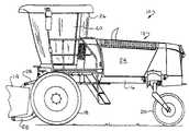
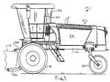
- FIG. 1is a side plan view of a windrower, with header
- FIG. 2is partial top plan view of the bottom assembly of the cab
- FIG. 3is a partial sectional view of the bottom assembly of the cab, taken along line 3 - 3 of FIG. 2 , also showing a portion of the main frame to which the cab is attached;
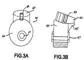
- FIGS. 3A and 3Bare detailed views of the side and front of the pivoting elastomeric mount
- FIG. 4is a partial sectional view of the bottom assembly of the cab, taken along line 4 - 4 of FIG. 2 , also showing a portion of the main frame to which the cab is attached;
- FIG. 5is a partial sectional view of the bottom assembly of the cab, taken along lines 5 - 5 of FIG. 2 .
- FIG. 1shows the two primary components of a self-propelled windrower 10 , i.e., tractor 12 and header 14 .
- Tractor 12has a main frame 16 , with a longitudinal horizontal axis from front to back, that is supported by a pair of drive wheels 18 (only one shown) on the forward portion thereof and a pair of rear wheels 20 adjacent the rear end.
- Main frame 16includes longitudinal and lateral structural elements that provide a fairly rigid and structurally strong skeletal assembly for the support of the various components.
- An engine, located under cowling 24 , a transmission and other components, all well known in the art,are supported on the main frame 16 and provide the power necessary for the machine to operate.
- a cab 26also supported on the main frame, encloses the operator's platform to provide an environmentally controlled location from which the windrower may be comfortably operated.
- Header 14may be of several designs, but typically comprises a cutting mechanism, either a sicklebar or rotary cutter, a feeder mechanism and conditioning rolls.
- the headeris supported by a hydraulic lift and flotation structure 28 that may be activated to selectively raise or lower the header between transport and operational positions.
- a hydraulic lift and flotation structure 28that may be activated to selectively raise or lower the header between transport and operational positions.
- the rotary cutteroperates at such speed and efficiency that operational speed of the windrower is limited not so much by the efficiency of the header, but more so by the comfort of the operator and the long term integrity of the windrower itself.
- the cab mounting and suspension system on the typical self-propelled windroweris such that bumps and irregularities in the field are directed through the chassis to the operator.
- the cab mounting and suspension system to be described hereinreduces this stress and discomfort, making it possible to operate the windrower at a higher ground speed and thus greater crop throughput.
- Cab 26is typically a four-sided structure, somewhat like a rectangular box with top and bottom assemblies. The sides may slope outwardly, especially the front portion, to increase the size of the operator's workspace without enlarging the footprint.
- the cabwould comprise four upright panel assemblies, with considerable glass to provide visual access to as much of the field or surrounding area as possible, a door, a roof and a floor or bottom assembly.
- the bottom assemblyis conventionally attached to the main frame 16 of the windrower, and may comprise several configurations, that may include structural components at various locations such as along the lower portion of the cab. Inside the cab there are located various necessary components such as a seat and a steering wheel, and various additional systems for operator comfort such as, for example, a heater and an air conditioner.
- FIG. 2shows an exemplary bottom assembly 30 , or floor of cab 26 , to have a generally rectangular shape with a curved front panel assembly 32 .
- a door 40( FIG. 1 ) is located in one of the side panel assemblies, and it is possible that each side panel assembly would have a door located in it, depending upon the designer's preferences and the operational requirements of the windrower.
- FIG. 3depicts the front mounting and suspension of the cab 26 .
- Each of the two front corners formed by bottom assembly 30 , front panel assembly 32 , side panel assembly 36 and side panel assembly 38is attached to main frame 16 by a pivoting elastomeric mount 42 .
- a generally cylindrically-shaped lower portion 44with an upper extension 45 , is affixed to a brace 46 , itself affixed to main frame 16 , by a yoke 48 and pivot pin 50 .
- the pinmay be either loose fitting or tight. If loose fitting, lower portion 44 rotates about pin 50 and slightly flexes due to the elastic characteristics of the material of which mount 42 is made in substantially any direction in the plane of the bottom assembly 30 .
- Extension 45protrudes from the side of portion 44 and forms a part thereof to increase the volume of material at the interface 52 between lower portion 44 and upper portion 60 . If the pin is tightly clamping the lower portion 44 , as is preferred, all of the pivoting occurs in the elastomeric material.
- lower portion 44has an off-center opening 47 through which pin 50 extends to pivotably affix mount 42 to yoke 48 .
- the term “off-center”is relative to the central axis of lower portion 44 , which is, as seen in FIG. 3A , circular.
- the pivoting movementis, in the embodiment where the pin 50 loosely clamps portion 44 , thus not limited to rotation about pin 50 , but also includes exaggerated flexure above the axis of pin 50 due to the off-center position of the pin.
- a threaded insert 49integrally formed with mount 42 , allows the mount to be bolted to bottom 30 .
- Pivoting elastomeric mounting assembly 42further includes an upper elastomeric portion 60 which is generally cylindrical in configuration.
- the upper and lower portionsare integrally formed at an angle for structural and function purposes as discussed above.
- Mount 42is made from an elastomeric material so that it can absorb a certain amount of shock through compression, expansion (stretching) and flexure.
- the preferred materialis rubber, but substantially any relatively hard elastomeric material will perform the necessary function.
- FIG. 4depicts the rear mounting and suspension of the cab 26 .
- Each of the two rear corners formed by bottom assembly 30 , rear panel assembly 34 , side panel assembly 36 and side panel assembly 38is attached to main frame 16 by a coil-over shock mounting assembly 70 .
- a shock absorber 72is affixed to a brace 74 , itself affixed to main frame 16 .
- a compression spring 76is positioned around the barrel of shock absorber 72 and held in place by upper and lower stops 78 , 80 , affixed to shock absorber 72 .
- the upper end of assembly 70is affixed to bottom assembly 30 by bracket 82 .
- the coil-over shock assemblycan compress approximately two inches and extend approximately one inch.
- a stabilizer bar 90located between the cab 26 and windrower main frame 16 across the back of the cab is a stabilizer bar 90 .
- the stabilizer baris mounted in pivoting rubber isolators 92 , 94 .
- Bar 90extends the full width of the cab to reduce the amount of movement of the cab from side to side as the ear pivots up and down through the range of the coil-over shocks. There are no adjustments or operator inputs required of this system, as it functions fully automatically once installation is completed.
- the biggest advantage of this cab mounting and suspension system in the windrower applicationis operator comfort, allowing higher ground speed for the unit. Also, the stress is greatly reduced in the cab weld assembly resulting in fewer joint weld failures in the cab.
- FIG. 5is a side view of the lower part of cab 26 . It shows the relative positions of the front pivoting elastomeric mount 42 and the coil-over shock mounting assembly 70 . The left and right sides are essentially the same.
Landscapes
- Engineering & Computer Science (AREA)
- General Engineering & Computer Science (AREA)
- Mechanical Engineering (AREA)
- Chemical & Material Sciences (AREA)
- Combustion & Propulsion (AREA)
- Transportation (AREA)
- Body Structure For Vehicles (AREA)
Abstract
Description
Claims (13)
Priority Applications (1)
| Application Number | Priority Date | Filing Date | Title |
|---|---|---|---|
| US10/969,892US7300100B2 (en) | 2004-10-21 | 2004-10-21 | Windrower cab mounting and suspension system |
Applications Claiming Priority (1)
| Application Number | Priority Date | Filing Date | Title |
|---|---|---|---|
| US10/969,892US7300100B2 (en) | 2004-10-21 | 2004-10-21 | Windrower cab mounting and suspension system |
Publications (2)
| Publication Number | Publication Date |
|---|---|
| US20060096269A1 US20060096269A1 (en) | 2006-05-11 |
| US7300100B2true US7300100B2 (en) | 2007-11-27 |
Family
ID=36314911
Family Applications (1)
| Application Number | Title | Priority Date | Filing Date |
|---|---|---|---|
| US10/969,892Expired - LifetimeUS7300100B2 (en) | 2004-10-21 | 2004-10-21 | Windrower cab mounting and suspension system |
Country Status (1)
| Country | Link |
|---|---|
| US (1) | US7300100B2 (en) |
Cited By (21)
| Publication number | Priority date | Publication date | Assignee | Title |
|---|---|---|---|---|
| US20070056787A1 (en)* | 2005-09-14 | 2007-03-15 | Haeusler Felix | Suspension device with watt's linkage |
| US20080252102A1 (en)* | 2007-04-12 | 2008-10-16 | Kubota Corporation | Vehicle with Cabin |
| US20100276959A1 (en)* | 2007-12-27 | 2010-11-04 | Doosan Infracore Co., Ltd. | Cabin mounting structure for construction machinery |
| US20110079457A1 (en)* | 2008-06-11 | 2011-04-07 | Valtra Oy Ab | Cab Suspensions |
| US20120043798A1 (en)* | 2010-08-18 | 2012-02-23 | Grammer Ag | Vehicle suspension device for vehicle seats or vehicle cabs |
| US20120193941A1 (en)* | 2009-10-05 | 2012-08-02 | Agco Sa | Utility Vehicle Cab Suspension |
| US8534646B2 (en) | 2010-07-08 | 2013-09-17 | Grammer Ag | Seat suspension device for a vehicle seat |
| US8678508B2 (en) | 2010-08-02 | 2014-03-25 | Grammer Ag | Horizontal springing means with inclination compensation |
| US8800977B2 (en) | 2010-12-15 | 2014-08-12 | Grammer Ag | Suspension device for vehicle seats and/or vehicle cabins having an elastomer member |
| US8807633B2 (en) | 2011-06-21 | 2014-08-19 | Cnh Industrial America Llc | Cab suspension system for an off-road vehicle |
| US8926012B2 (en) | 2010-08-31 | 2015-01-06 | Grammer Ag | Vehicle seats for vehicles |
| US8960802B2 (en) | 2010-11-29 | 2015-02-24 | Grammer Ag | Vehicle seat with guided scissor arms |
| US8973967B2 (en) | 2011-09-15 | 2015-03-10 | Grammer Ag | Vehicle seat, motor vehicle and method for spring-mounting a vehicle seat |
| US9238902B2 (en) | 2011-04-14 | 2016-01-19 | Vermeer Manufacturing Company | Cab suspension system for a machine adapted to surface excavate rock or like materials |
| US9266452B2 (en) | 2010-12-08 | 2016-02-23 | Grammer Ag | Vehicle vibration device for vehicle seats or vehicle cabs |
| US9376042B2 (en) | 2010-08-04 | 2016-06-28 | Grammer Ag | Horizontal springing device for vehicle seats with elastomer spring element with progressive spring characteristic curve |
| US9549503B2 (en) | 2012-07-02 | 2017-01-24 | Cnh Industrial America Llc | Mount for a cabin of an agricultural harvester |
| US10029744B2 (en) | 2013-03-14 | 2018-07-24 | Hendrickson Usa, L.L.C. | Vehicle cab suspension |
| US10065541B2 (en) | 2015-08-10 | 2018-09-04 | Grammer Ag | Horizontal vibration device for a vehicle seat |
| US11173969B2 (en) | 2017-05-01 | 2021-11-16 | Agco Corporation | Four-point cab suspension system |
| US20250263133A1 (en)* | 2024-02-19 | 2025-08-21 | CNH Industrial Brasil Ltda. | System and method for work vehicle |
Families Citing this family (3)
| Publication number | Priority date | Publication date | Assignee | Title |
|---|---|---|---|---|
| US8475108B2 (en)* | 2007-10-17 | 2013-07-02 | Castlewood Medical Technologies Llc | System and method for moving large objects |
| WO2018203125A1 (en)* | 2017-05-01 | 2018-11-08 | Agco Corporation | Two-point cab suspension system |
| US11339553B2 (en)* | 2020-04-23 | 2022-05-24 | Deere & Company | Cab viscous mount |
Citations (22)
| Publication number | Priority date | Publication date | Assignee | Title |
|---|---|---|---|---|
| US3554596A (en)* | 1969-02-06 | 1971-01-12 | White Motor Corp | Cab support |
| US3841694A (en)* | 1973-11-01 | 1974-10-15 | Gen Motors Corp | Vehicle cab mounting means |
| US3966009A (en) | 1974-12-17 | 1976-06-29 | Mack Trucks, Inc. | Vehicle cab mounting arrangement |
| US4061393A (en) | 1975-12-15 | 1977-12-06 | Caterpillar Tractor Co. | Shock mounted tilting operator platform |
| US4275918A (en) | 1978-08-11 | 1981-06-30 | Centro Ricerche Fiat S.P.A. | Resilient suspension for the cab of an agricultural tractor |
| US4452329A (en) | 1982-12-13 | 1984-06-05 | Paccar Inc. | Suspension for a truck tilt cab |
| US4470477A (en)* | 1981-10-23 | 1984-09-11 | Dunlop Limited | Hydropneumatic suspensions |
| US4638878A (en) | 1984-10-03 | 1987-01-27 | Kloeckner-Humboldt-Deutz Ag | Device for the cushioned mounting of a tractor cab |
| US4989684A (en)* | 1989-07-25 | 1991-02-05 | Richard Conaway | Suspension device for the cab of a truck vehicle |
| US5044455A (en)* | 1990-02-16 | 1991-09-03 | Navistar International Transportion Corp. | Actively controlled truck cab suspension |
| WO1993019973A1 (en) | 1992-04-07 | 1993-10-14 | Ab Volvo | Shock absorbing and sprung suspension system |
| US5398774A (en) | 1991-05-03 | 1995-03-21 | Ab Volvo | End stop arrangement for a vehicle cabin |
| US5553911A (en)* | 1994-12-15 | 1996-09-10 | Volvo Gm Heavy Truck Corporation | Heavy duty motor vehicle cab suspension |
| US5633452A (en)* | 1996-03-29 | 1997-05-27 | Deere & Company | Low pressure warning for hydraulic system of platform float suspension |
| US6073714A (en) | 1999-02-25 | 2000-06-13 | Freightliner Corporation | Vehicle cab suspension system |
| US6168229B1 (en) | 1999-01-12 | 2001-01-02 | Link Mfg., Ltd. | Vehicle cab suspension |
| US6478102B1 (en)* | 2001-04-21 | 2002-11-12 | International Truck Intellectual Property Company, L.L.C. | Vehicle body suspension system |
| US6540283B1 (en) | 1999-02-12 | 2003-04-01 | Scania Cv Ag (Publ) | Method and device for suspension of a cab on a vehicle frame |
| US6598932B2 (en) | 2001-02-17 | 2003-07-29 | Zf Sachs Ag | Driver's cab suspension |
| US6619728B1 (en) | 1999-08-12 | 2003-09-16 | Hydac Technology Gmbh | Suspension system, especially cab suspension system |
| US20040080181A1 (en) | 2002-10-24 | 2004-04-29 | Puterbaugh Benjamin S | Truck cab suspension system |
| US6758294B2 (en)* | 2002-06-10 | 2004-07-06 | Volvo Trucks North America, Inc. | Laterally damped panhard rod cab suspension |
- 2004
- 2004-10-21USUS10/969,892patent/US7300100B2/ennot_activeExpired - Lifetime
Patent Citations (22)
| Publication number | Priority date | Publication date | Assignee | Title |
|---|---|---|---|---|
| US3554596A (en)* | 1969-02-06 | 1971-01-12 | White Motor Corp | Cab support |
| US3841694A (en)* | 1973-11-01 | 1974-10-15 | Gen Motors Corp | Vehicle cab mounting means |
| US3966009A (en) | 1974-12-17 | 1976-06-29 | Mack Trucks, Inc. | Vehicle cab mounting arrangement |
| US4061393A (en) | 1975-12-15 | 1977-12-06 | Caterpillar Tractor Co. | Shock mounted tilting operator platform |
| US4275918A (en) | 1978-08-11 | 1981-06-30 | Centro Ricerche Fiat S.P.A. | Resilient suspension for the cab of an agricultural tractor |
| US4470477A (en)* | 1981-10-23 | 1984-09-11 | Dunlop Limited | Hydropneumatic suspensions |
| US4452329A (en) | 1982-12-13 | 1984-06-05 | Paccar Inc. | Suspension for a truck tilt cab |
| US4638878A (en) | 1984-10-03 | 1987-01-27 | Kloeckner-Humboldt-Deutz Ag | Device for the cushioned mounting of a tractor cab |
| US4989684A (en)* | 1989-07-25 | 1991-02-05 | Richard Conaway | Suspension device for the cab of a truck vehicle |
| US5044455A (en)* | 1990-02-16 | 1991-09-03 | Navistar International Transportion Corp. | Actively controlled truck cab suspension |
| US5398774A (en) | 1991-05-03 | 1995-03-21 | Ab Volvo | End stop arrangement for a vehicle cabin |
| WO1993019973A1 (en) | 1992-04-07 | 1993-10-14 | Ab Volvo | Shock absorbing and sprung suspension system |
| US5553911A (en)* | 1994-12-15 | 1996-09-10 | Volvo Gm Heavy Truck Corporation | Heavy duty motor vehicle cab suspension |
| US5633452A (en)* | 1996-03-29 | 1997-05-27 | Deere & Company | Low pressure warning for hydraulic system of platform float suspension |
| US6168229B1 (en) | 1999-01-12 | 2001-01-02 | Link Mfg., Ltd. | Vehicle cab suspension |
| US6540283B1 (en) | 1999-02-12 | 2003-04-01 | Scania Cv Ag (Publ) | Method and device for suspension of a cab on a vehicle frame |
| US6073714A (en) | 1999-02-25 | 2000-06-13 | Freightliner Corporation | Vehicle cab suspension system |
| US6619728B1 (en) | 1999-08-12 | 2003-09-16 | Hydac Technology Gmbh | Suspension system, especially cab suspension system |
| US6598932B2 (en) | 2001-02-17 | 2003-07-29 | Zf Sachs Ag | Driver's cab suspension |
| US6478102B1 (en)* | 2001-04-21 | 2002-11-12 | International Truck Intellectual Property Company, L.L.C. | Vehicle body suspension system |
| US6758294B2 (en)* | 2002-06-10 | 2004-07-06 | Volvo Trucks North America, Inc. | Laterally damped panhard rod cab suspension |
| US20040080181A1 (en) | 2002-10-24 | 2004-04-29 | Puterbaugh Benjamin S | Truck cab suspension system |
Cited By (31)
| Publication number | Priority date | Publication date | Assignee | Title |
|---|---|---|---|---|
| US7695054B2 (en)* | 2005-09-14 | 2010-04-13 | Zf Friedrichshafen Ag | Suspension device with Watt's linkage |
| US20070056787A1 (en)* | 2005-09-14 | 2007-03-15 | Haeusler Felix | Suspension device with watt's linkage |
| US8104826B2 (en)* | 2007-04-12 | 2012-01-31 | Kubota Corporation | Vehicle with cabin |
| US8491041B2 (en)* | 2007-04-12 | 2013-07-23 | Kubota Corporation | Vehicle with cabin |
| US20100244488A1 (en)* | 2007-04-12 | 2010-09-30 | Kubota Corporation | Vehicle With Cabin |
| US20100253115A1 (en)* | 2007-04-12 | 2010-10-07 | Kubota Corporation | Vehicle With Cabin |
| US7703840B2 (en)* | 2007-04-12 | 2010-04-27 | Kubota Corporation | Vehicle with cabin |
| US20080252102A1 (en)* | 2007-04-12 | 2008-10-16 | Kubota Corporation | Vehicle with Cabin |
| US20100276959A1 (en)* | 2007-12-27 | 2010-11-04 | Doosan Infracore Co., Ltd. | Cabin mounting structure for construction machinery |
| US8356858B2 (en)* | 2007-12-27 | 2013-01-22 | Doosan Infracore Co., Ltd. | Cabin mounting structure for construction machinery |
| US8820456B2 (en)* | 2008-06-11 | 2014-09-02 | Voltra Oy Ab | Cab suspensions |
| US20110079457A1 (en)* | 2008-06-11 | 2011-04-07 | Valtra Oy Ab | Cab Suspensions |
| US20120193941A1 (en)* | 2009-10-05 | 2012-08-02 | Agco Sa | Utility Vehicle Cab Suspension |
| US8678477B2 (en)* | 2009-10-05 | 2014-03-25 | Agco Sa | Utility vehicle cab suspension |
| US8534646B2 (en) | 2010-07-08 | 2013-09-17 | Grammer Ag | Seat suspension device for a vehicle seat |
| US8678508B2 (en) | 2010-08-02 | 2014-03-25 | Grammer Ag | Horizontal springing means with inclination compensation |
| US9376042B2 (en) | 2010-08-04 | 2016-06-28 | Grammer Ag | Horizontal springing device for vehicle seats with elastomer spring element with progressive spring characteristic curve |
| US8607910B2 (en)* | 2010-08-18 | 2013-12-17 | Grammer Ag | Vehicle suspension device for vehicle seats or vehicle cabs |
| US20120043798A1 (en)* | 2010-08-18 | 2012-02-23 | Grammer Ag | Vehicle suspension device for vehicle seats or vehicle cabs |
| US8926012B2 (en) | 2010-08-31 | 2015-01-06 | Grammer Ag | Vehicle seats for vehicles |
| US8960802B2 (en) | 2010-11-29 | 2015-02-24 | Grammer Ag | Vehicle seat with guided scissor arms |
| US9266452B2 (en) | 2010-12-08 | 2016-02-23 | Grammer Ag | Vehicle vibration device for vehicle seats or vehicle cabs |
| US8800977B2 (en) | 2010-12-15 | 2014-08-12 | Grammer Ag | Suspension device for vehicle seats and/or vehicle cabins having an elastomer member |
| US9238902B2 (en) | 2011-04-14 | 2016-01-19 | Vermeer Manufacturing Company | Cab suspension system for a machine adapted to surface excavate rock or like materials |
| US8807633B2 (en) | 2011-06-21 | 2014-08-19 | Cnh Industrial America Llc | Cab suspension system for an off-road vehicle |
| US8973967B2 (en) | 2011-09-15 | 2015-03-10 | Grammer Ag | Vehicle seat, motor vehicle and method for spring-mounting a vehicle seat |
| US9549503B2 (en) | 2012-07-02 | 2017-01-24 | Cnh Industrial America Llc | Mount for a cabin of an agricultural harvester |
| US10029744B2 (en) | 2013-03-14 | 2018-07-24 | Hendrickson Usa, L.L.C. | Vehicle cab suspension |
| US10065541B2 (en) | 2015-08-10 | 2018-09-04 | Grammer Ag | Horizontal vibration device for a vehicle seat |
| US11173969B2 (en) | 2017-05-01 | 2021-11-16 | Agco Corporation | Four-point cab suspension system |
| US20250263133A1 (en)* | 2024-02-19 | 2025-08-21 | CNH Industrial Brasil Ltda. | System and method for work vehicle |
Also Published As
| Publication number | Publication date |
|---|---|
| US20060096269A1 (en) | 2006-05-11 |
Similar Documents
| Publication | Publication Date | Title |
|---|---|---|
| US7300100B2 (en) | Windrower cab mounting and suspension system | |
| US8267416B2 (en) | Independent rear suspension | |
| US6179328B1 (en) | Vehicle rear suspension apparatus | |
| US10343729B2 (en) | Suspension system for a work vehicle | |
| US8132822B2 (en) | Compression and torsion damping wheel suspension system | |
| US12054082B2 (en) | Suspension system for a utility vehicle | |
| CN111660743A (en) | Rear wheel suspension | |
| US7252169B2 (en) | Windrower rear axle suspension system | |
| US11173969B2 (en) | Four-point cab suspension system | |
| EP1275283A2 (en) | A pull-type agricultural machine, in particular a mower | |
| US3732941A (en) | Vehicle chassis resiliently supported on main frame | |
| US5579860A (en) | Three-point cab mounting system for a one man cab using one rear mount | |
| US20110192128A1 (en) | Compression and torsion damping wheel suspension system | |
| EP0301782B1 (en) | Vehicle wheel suspension unit | |
| JP3957767B2 (en) | Steering assembly | |
| US4043584A (en) | Vehicle suspension and stabilizer system | |
| US7607671B2 (en) | Light weight suspension system | |
| US11407344B2 (en) | Work vehicle having driver's seat | |
| US20230256876A1 (en) | Lawn care vehicle with improved seat isolation | |
| JP2003014037A (en) | Dynamic damper for viehicle | |
| EP0102772B1 (en) | Improvements relating to vehicle suspensions | |
| US11772716B1 (en) | Suspension system for an operator station of a work vehicle | |
| US12233960B2 (en) | Working vehicle | |
| JP3151373B2 (en) | Moore | |
| JPH03281490A (en) | Structure for pivotally supporting upper arm of front wheel suspension device for motor-cycle |
Legal Events
| Date | Code | Title | Description |
|---|---|---|---|
| AS | Assignment | Owner name:CNH AMERICA LLC, PENNSYLVANIA Free format text:ASSIGNMENT OF ASSIGNORS INTEREST;ASSIGNORS:MCLEAN, KENNETH W.;OSBORNE, DONALD L.;DECHRISTOPHER, DAVID M.;REEL/FRAME:015927/0497 Effective date:20041021 | |
| STCF | Information on status: patent grant | Free format text:PATENTED CASE | |
| AS | Assignment | Owner name:BLUE LEAF I.P. INC., DELAWARE Free format text:ASSIGNMENT OF ASSIGNORS INTEREST;ASSIGNOR:CNH AMERICA LLC;REEL/FRAME:020227/0024 Effective date:20071210 Owner name:BLUE LEAF I.P. INC.,DELAWARE Free format text:ASSIGNMENT OF ASSIGNORS INTEREST;ASSIGNOR:CNH AMERICA LLC;REEL/FRAME:020227/0024 Effective date:20071210 | |
| FPAY | Fee payment | Year of fee payment:4 | |
| FPAY | Fee payment | Year of fee payment:8 | |
| MAFP | Maintenance fee payment | Free format text:PAYMENT OF MAINTENANCE FEE, 12TH YEAR, LARGE ENTITY (ORIGINAL EVENT CODE: M1553); ENTITY STATUS OF PATENT OWNER: LARGE ENTITY Year of fee payment:12 |