US7299952B2 - Container closure and method of assembly - Google Patents
Container closure and method of assemblyDownload PDFInfo
- Publication number
- US7299952B2 US7299952B2US11/175,587US17558705AUS7299952B2US 7299952 B2US7299952 B2US 7299952B2US 17558705 AUS17558705 AUS 17558705AUS 7299952 B2US7299952 B2US 7299952B2
- Authority
- US
- United States
- Prior art keywords
- valve
- lid
- base
- closure
- adapter
- Prior art date
- Legal status (The legal status is an assumption and is not a legal conclusion. Google has not performed a legal analysis and makes no representation as to the accuracy of the status listed.)
- Expired - Lifetime, expires
Links
Images


Classifications
- B—PERFORMING OPERATIONS; TRANSPORTING
- B29—WORKING OF PLASTICS; WORKING OF SUBSTANCES IN A PLASTIC STATE IN GENERAL
- B29C—SHAPING OR JOINING OF PLASTICS; SHAPING OF MATERIAL IN A PLASTIC STATE, NOT OTHERWISE PROVIDED FOR; AFTER-TREATMENT OF THE SHAPED PRODUCTS, e.g. REPAIRING
- B29C45/00—Injection moulding, i.e. forcing the required volume of moulding material through a nozzle into a closed mould; Apparatus therefor
- B29C45/0081—Injection moulding, i.e. forcing the required volume of moulding material through a nozzle into a closed mould; Apparatus therefor of objects with parts connected by a thin section, e.g. hinge, tear line
- B—PERFORMING OPERATIONS; TRANSPORTING
- B29—WORKING OF PLASTICS; WORKING OF SUBSTANCES IN A PLASTIC STATE IN GENERAL
- B29C—SHAPING OR JOINING OF PLASTICS; SHAPING OF MATERIAL IN A PLASTIC STATE, NOT OTHERWISE PROVIDED FOR; AFTER-TREATMENT OF THE SHAPED PRODUCTS, e.g. REPAIRING
- B29C45/00—Injection moulding, i.e. forcing the required volume of moulding material through a nozzle into a closed mould; Apparatus therefor
- B29C45/16—Making multilayered or multicoloured articles
- B—PERFORMING OPERATIONS; TRANSPORTING
- B65—CONVEYING; PACKING; STORING; HANDLING THIN OR FILAMENTARY MATERIAL
- B65D—CONTAINERS FOR STORAGE OR TRANSPORT OF ARTICLES OR MATERIALS, e.g. BAGS, BARRELS, BOTTLES, BOXES, CANS, CARTONS, CRATES, DRUMS, JARS, TANKS, HOPPERS, FORWARDING CONTAINERS; ACCESSORIES, CLOSURES, OR FITTINGS THEREFOR; PACKAGING ELEMENTS; PACKAGES
- B65D47/00—Closures with filling and discharging, or with discharging, devices
- B65D47/04—Closures with discharging devices other than pumps
- B65D47/06—Closures with discharging devices other than pumps with pouring spouts or tubes; with discharge nozzles or passages
- B65D47/08—Closures with discharging devices other than pumps with pouring spouts or tubes; with discharge nozzles or passages having articulated or hinged closures
- B65D47/0804—Closures with discharging devices other than pumps with pouring spouts or tubes; with discharge nozzles or passages having articulated or hinged closures integrally formed with the base element provided with the spout or discharge passage
- B65D47/0833—Hinges without elastic bias
- B65D47/0838—Hinges without elastic bias located at an edge of the base element
- B65D47/0842—Hinges without elastic bias located at an edge of the base element consisting of a strap of flexible material
- B—PERFORMING OPERATIONS; TRANSPORTING
- B65—CONVEYING; PACKING; STORING; HANDLING THIN OR FILAMENTARY MATERIAL
- B65D—CONTAINERS FOR STORAGE OR TRANSPORT OF ARTICLES OR MATERIALS, e.g. BAGS, BARRELS, BOTTLES, BOXES, CANS, CARTONS, CRATES, DRUMS, JARS, TANKS, HOPPERS, FORWARDING CONTAINERS; ACCESSORIES, CLOSURES, OR FITTINGS THEREFOR; PACKAGING ELEMENTS; PACKAGES
- B65D47/00—Closures with filling and discharging, or with discharging, devices
- B65D47/04—Closures with discharging devices other than pumps
- B65D47/20—Closures with discharging devices other than pumps comprising hand-operated members for controlling discharge
- B65D47/2018—Closures with discharging devices other than pumps comprising hand-operated members for controlling discharge comprising a valve or like element which is opened or closed by deformation of the container or closure
- B65D47/2031—Closures with discharging devices other than pumps comprising hand-operated members for controlling discharge comprising a valve or like element which is opened or closed by deformation of the container or closure the element being formed by a slit, narrow opening or constrictable spout, the size of the outlet passage being able to be varied by increasing or decreasing the pressure
- B—PERFORMING OPERATIONS; TRANSPORTING
- B29—WORKING OF PLASTICS; WORKING OF SUBSTANCES IN A PLASTIC STATE IN GENERAL
- B29L—INDEXING SCHEME ASSOCIATED WITH SUBCLASS B29C, RELATING TO PARTICULAR ARTICLES
- B29L2031/00—Other particular articles
- B29L2031/56—Stoppers or lids for bottles, jars, or the like, e.g. closures
- B29L2031/565—Stoppers or lids for bottles, jars, or the like, e.g. closures for containers
Definitions
- the inventionrelates generally to containers used to dispense fluids and other substances, such as foodstuffs (for example, ketchup) or cosmetics. More particularly, the invention relates to a closure for a squeeze-type container wherein contents can be discharged from the container through a self-closing valve.
- U.S. Pat. No. 6,230,940Manning et al.
- U.S. Pat. No. 6,530,504Socier
- U.S. Pat. No. 5,927,566discloses a self-sealing valve bonded by a molding process to a closure.
- U.S. Pat. No. 5,743,443discloses a valve bonded to a base, the valve/base combination in turn being retained against a container neck by a fastening element.
- the inventionis a closure for use with a container having a container neck.
- the closureincludes a base with a top that have a skirt depending from a peripheral edge of the top.
- the basehas a valve mount portion formed on the base top.
- the valve mount portionincludes an attachment surface.
- the baseis made from a first thermoplastic material.
- a valve made from a second thermoplastic materialincludes a flexible central portion with at least one valve opening.
- the valvealso includes an outer peripheral portion that is molded onto the attachment surface of the valve mount portion.
- a lidis hingedly attached to the base and rotates between an open position and a closed position.
- the lidhas an inner surface.
- a sealing rimis located on the lid and extends downward from the inside surface when the lid is in its closed position.
- the sealing rimincludes a lower tip which is positioned so as to contact the outer peripheral portion of the valve. The contact between the tip and the outer peripheral portion forms a substantial seal between the sealing rim and the outer peripheral portion.
- the valve mount portionis an adapter formed from a first thermoplastic material and includes a housing with a passage extending through the adapter.
- the adapterincludes a first end and a second end. At least one adapter connector is formed on the adapter at or near the first end.
- the valve attachment surfaceis formed on the adapter at or near the second end.
- the adapter connectoris engaged with a base connector on the base.
- the lidincludes a protrusion positioned on the inner surface of the lid and located to as to be positioned adjacent to the central portion of the valve when the lid is in its closed position.
- the protrusionis designed to inhibit the valve from opening when the lid is in the closed position.
- the sealing rimis substantially cylindrical in shape and sized to locally compress the outer peripheral portion of the valve when the lid is in its closed position.
- FIG. 1is a perspective view of a first preferred embodiment of the closure of the present invention shown removed from a container and showing a lid of the closure in an open position.
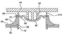
- FIG. 2is an exploded cross-sectional view of the closure of FIG. 1 .
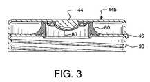
- FIG. 3is cross-sectional view of the closure of FIGS. 1 and 2 , showing the lid in a closed position.
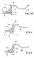
- FIG. 3Ais an enlarged view of a portion of the closure of FIGS. 1-3 , showing connections between first embodiments of a valve, an adapter and a base.
- FIG. 4is a view similar to FIG. 3A , showing connections between second embodiments of the valve, adapter and base.
- FIG. 5is a view similar to FIG. 3A , showing connections between third embodiments of the valve, adapter and base.
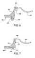
- FIG. 6is a view similar to FIG. 3A , showing connections between fourth embodiments of the valve, adapter and base.
- FIG. 7is a view similar to FIG. 3A , showing connections between fifth embodiments of the valve, adapter and base.
- FIG. 8is an enlarged cross-sectional view of a portion of the closure of FIG. 1 including a novel cap for assisting in sealing the valve.
- FIG. 8Ais an enlarged detail of a portion of the closure of FIG. 8 .
- multi-material moldingmeans any conventional molding process in which two or more materials are injected simultaneously or in sequence into a single mold during a single molding cycle. Multi-material molding is intended to include co-injection molding, bi-injection molding, two-shot molding and insert molding techniques well known to those of ordinary skill in the art of injection molding.
- a closure for a containeris indicated generally by the reference numeral 20 .
- the closure 20is adapted for use with a conventional container 10 .
- the container 10comprises a container neck 12 , defining a container opening 14 .
- the container neck 12may be provided with an external helical thread 16 for threaded engagement with the closure 20 .
- the container 10 and closure 20may be connectable with inter-engaging snap elements (e.g., raised beads and recesses) (not shown).
- the closure 20could be permanently affixed to the container neck 12 by any number of conventional techniques including induction melting, ultrasonic melting or use of adhesive.
- the container 10is preferably squeezable with at least one flexible wall capable of being manually deformed to compress the contents therein and increase the pressure within the container to force the contents out of the container.
- the closure 20is an assembly of a base 30 , an adapter 60 and a valve 80 .
- the base 30includes a top 32 having an outer periphery.
- An opening 34is formed in the top 32 , the opening 34 being surrounded by a lip 36 .
- the lip 36is sized and shaped to be engaged by an adapter connector 70 , and thus the lip 36 serves as a base connector 38 .
- a base skirt 40depends from the outer periphery, generally perpendicular to the top 32 .
- a base helical internal thread 42may be provided on an interior surface of the base skirt 40 , allowing the base 30 to be connected to the container neck 12 by threaded engagement of the internal thread 42 with the external thread 16 . While threads are shown in the figures, those skilled in the art would readily appreciate that many other conventional attachments may be used for a engaging the base with the container neck.
- the base 30further preferably includes a lid 44 hingedly attached to the base 30 by a hinge 46 .
- the hingepermits that lid 44 to rotate or pivot between an open position 44 a and a closed position 44 b .
- the lid 44includes a lid top 48 having a periphery, and a lid skirt 50 extending from the lid top 48 .
- the lid 44includes a protrusion 52 on an interior side of the top 48 of the lid.
- the protrusion 52is preferably sized, shaped and positioned to prevent a valve aperture 86 from opening when the lid 44 is in the closed position 44 b.
- the base 30including the lid 44 , is preferably fabricated using conventional thermoplastic materials such as polyolefins, including polypropylene, and using conventional fabrication techniques, such as injection molding, well known to those of ordinary skill in the art of bottle closures.
- the adapter 60is formed from a first thermoplastic material, preferably a polyolefin material such as polypropylene.
- the adapter 60includes a shell or housing 62 , which is preferably cylindrical in shape and which defines a passage 64 through the adapter.
- the adapter 60has a first end 66 and a second end 68 .
- At least one adapter connector 70is provided proximate the first end 66 .
- the adapter connector 70is a hook element that engages and latches with the base connector 38 to connect the adapter 60 to the base 30 .
- the adapter 60further includes a valve attachment surface 72 . It is along this surface 72 that the valve 80 is connected to the adapter 60 .
- numerous variationsare possible for forming the inter-engaging base and adapter connectors 38 , 70 , as well as the valve attachment surface 72 .
- the valve 80is formed from a second thermoplastic material, preferably a thermoplastic elastomer.
- the valve 80has a resiliently flexible central portion 82 provided with at least one opening 84 forming an aperture 86 .
- the aperture 86has a closed position 86 a and an open position 86 b .
- the resiliency of the flexible central portion 82biases the aperture 86 into the closed position 86 a .
- the central portion 82flexes from a retracted position 82 a into an extended position 82 b , such that the aperture 86 moves to the open position 86 b .
- the resilient nature of the aperture 86biases it back to the closed position 86 a .
- at least the central portion 82 of the valve 80has a substantially uniform wall thickness.
- the valve 80includes an outer peripheral portion 88 .
- the valve outer peripheral portion 88is molded to the adapter 60 at the attachment surface 72 thereby bonding the valve 80 to the adapter 60 to form an adapter and valve assembly.
- a pleated portion 90forming a bellows-like fold, may be provided to allow increased flexure of the central portion 82 .
- the pleated portion 90acts to bias the central portion 82 into the retracted position 82 a.
- FIGS. 1-3illustrate a presently preferred embodiment wherein the base opening 34 is formed in the top 32 .
- the base opening 34(and the base connector 38 ) could be positioned elsewhere on the base 30 , for example on a side portion of the base 30 .
- the adapter and valve assembly of the closure 20are formed by a multi-material molding process.
- this processentails sequentially injecting first and second thermoplastic materials into a single mold such that the adapter 60 is formed from the first thermoplastic material, the valve 80 is formed from the second thermoplastic material and a physical bond between the adapter 60 and valve 80 is formed during the molding process, eliminating the need for any subsequent assembly using adhesive or other types of fasteners to join the adapter 60 to the valve 80 .
- the assemblyis connected to the base to form the closure 20 .
- the connectionis made by engagement of the adapter connector 70 with the base connector 38 .
- numerous embodiments of the adapter connector and base connectorare possible.
- the connectionis one that is performed in a manner that prevents subsequent disconnection.
- the connectionbe a snap connection wherein the assembly is snapped downward on, onto or into engagement with the base, thus forming the complete closure.
- the closureAfter the closure is formed, it is connected to the container neck, for example, by screwing the closure 20 onto the container neck 12 (for containers 10 having a conventional threaded design), snapping the closure 20 onto the container neck 12 (for containers having a conventional snap-on design), or by permanently affixing the closure 20 to the container neck 12 .
- the adapter 60Upon assembly of the closure 20 to the container 10 , the adapter 60 does not interface directly with the container neck 12 . That is, the valve and adapter assembly, when incorporated into the closure 20 and installed on the container 10 , is separated from the container 10 by the base 30 . In this manner, as the valve and adapter assembly does not directly connect or otherwise directly interface with the container, the design of the valve and adapter assembly is generally independent of the design of the container, and a single valve and adapter assembly design may be adapted for use with different types of containers.
- the lid 44In use, the lid 44 is placed in the open position 44 a and the container 10 is squeezed, pressurizing and forcing contents of the container 10 against an interior side of the valve central portion 82 . When the pressure within the container exceeds the predetermined level necessary to open the aperture 86 , contents of the container 10 are dispensed. When the pressure within the container 10 falls below the predetermined level, the aperture 86 moves back to the closed position 86 a . After use, the lid 44 is rotated back into the closed position 44 b . As discussed above, the lid preferably includes a lid protrusion 52 formed on the lid that moves with the remainder of the lid 44 , into a position adjacent to the aperture 86 .
- the lid protrusion 52blocks the aperture 86 so as to prevent or inhibit the valve central portion 82 from flexing and/or rotating open.
- the lid protrusion 52operates to prevent discharge of the container contents should the container 10 be squeezed when the lid 44 is in the closed position 44 b.
- second through fifth embodiments of the base 30 , adapter 60 and valve 80illustrate that connections between the base 30 and adapter 60 and between the adapter 60 and valve 80 can be made in various ways.
- elements of the second through fifth embodiments corresponding to like elements of the first embodimentare numbered in increments of 100, 200, 300, 400 and 500, respectively, above the reference number of the corresponding first embodiment element.
- FIG. 4A second embodiment base 130 , adapter 160 and valve 180 are illustrated in FIG. 4 .
- the adapter connector 170is in the form of a pin, having a hook-like portion adapted to engage the base connector 138 .
- the base connector 138is in the form of an opening in the base 130 , and is sized and shaped to receive and engage the adapter connector 170 .
- the peripheral portion 188 of the valve 180is bifurcated and engages the valve attachment surface 172 along multiple planes.
- a third embodiment base 230 , adapter 260 and valve 280are illustrated in FIG. 5 .
- the adapter connector 270is in the form of a raised bead, adapted to engage the base connector 238 , in the form of a recess in the base 230 , sized and shaped to receive and engage the adapter connector 270 .
- the peripheral portion 288 of the valve 280engages the valve attachment surface 272 along an exterior portion of the adapter 260 .
- a fourth embodiment base 330 , adapter 360 and valve 380are illustrated in FIG. 6 .
- the adapter connector 370is in the form of a shaft having an outer extent with a first dimension, adapted to engage the base connector 338 , in the form of a recess in the base 330 , the recess having an inner bore with a second dimension such that an interference fit occurs when the adapter connector 370 is inserted into the base connector 338 .
- the peripheral portion 388 of the valve 380forms a channel-like structure which engages the valve attachment surface 372 of the adapter 360 in an interlocking fashion.
- a fifth embodiment base 430 , adapter 460 and valve 480are illustrated in FIG. 7 .
- the adapter connector 470has a plurality of corrugated or tooth-like structures which are adapted to engage similar corrugated structures on the base connector 438 .
- the peripheral portion 488 of the valve 480is adapted to be received within a slot forming the valve attachment surface 472 of the adapter 460 .
- the lid 44preferably includes a protrusion 52 which is designed to lie adjacent to or against the valve in the closed position so as to prevent inadvertent opening or flexure of the valve central portion 82 .
- the lid 44includes not only the protrusion 52 , which in this embodiment is preferably one or more spaced apart ribs 200 , but also a sealing rim 210 that extends from the lower surface of the lid 44 and is positioned to engage the valve outer peripheral portion 88 at the point where it mounted to the attachment surface 72 of the adapter 60 .
- the sealing rimis designed to provide a physical engagement or seal between the lid 44 and the valve, thus preventing material from passing to or from the valve are inside the lid. More particularly, as shown in FIGS. 8 and 8A , the sealing rim 210 extends down from the lower or inside surface of the lid 44 and has a length of sufficient dimension to contact, and more preferably, press into the sealing outer peripheral portion 88 of the valve. As shown in FIG. 8A , the sealing rim 210 locally compresses the elastic valve material, thus creating a tight seal.
- the sealing rim 210may include a tip end designed to facilitate a tight seal, such as a pointed tip as shown.
- the sealing rim 210may be completely cylindrical so as to completely seal the outer peripheral portion 88 .
- the sealing rim 210my constitute a series of spaced apart rim portions to contact the outer peripheral portion at spaced apart areas.
- the rim portionmay be formed as a substantially rigid member as shown in the figures, or may be designed to flex to some degree to accommodate manufacturing tolerances.
- the lidneed not include both.
- the sealing rim 210is designed to provide sealing around the valve, it may be desirable to not include a protrusion in the lid.
Landscapes
- Engineering & Computer Science (AREA)
- Mechanical Engineering (AREA)
- Manufacturing & Machinery (AREA)
- Closures For Containers (AREA)
Abstract
Description
Claims (11)
Priority Applications (1)
| Application Number | Priority Date | Filing Date | Title |
|---|---|---|---|
| US11/175,587US7299952B2 (en) | 2004-07-08 | 2005-07-06 | Container closure and method of assembly |
Applications Claiming Priority (2)
| Application Number | Priority Date | Filing Date | Title |
|---|---|---|---|
| US10/888,162US7152763B2 (en) | 2004-07-08 | 2004-07-08 | Container closure and method of assembly |
| US11/175,587US7299952B2 (en) | 2004-07-08 | 2005-07-06 | Container closure and method of assembly |
Related Parent Applications (1)
| Application Number | Title | Priority Date | Filing Date |
|---|---|---|---|
| US10/888,162Continuation-In-PartUS7152763B2 (en) | 2004-07-08 | 2004-07-08 | Container closure and method of assembly |
Publications (2)
| Publication Number | Publication Date |
|---|---|
| US20060006203A1 US20060006203A1 (en) | 2006-01-12 |
| US7299952B2true US7299952B2 (en) | 2007-11-27 |
Family
ID=35540256
Family Applications (2)
| Application Number | Title | Priority Date | Filing Date |
|---|---|---|---|
| US10/888,162Expired - LifetimeUS7152763B2 (en) | 2004-07-08 | 2004-07-08 | Container closure and method of assembly |
| US11/175,587Expired - LifetimeUS7299952B2 (en) | 2004-07-08 | 2005-07-06 | Container closure and method of assembly |
Family Applications Before (1)
| Application Number | Title | Priority Date | Filing Date |
|---|---|---|---|
| US10/888,162Expired - LifetimeUS7152763B2 (en) | 2004-07-08 | 2004-07-08 | Container closure and method of assembly |
Country Status (5)
| Country | Link |
|---|---|
| US (2) | US7152763B2 (en) |
| EP (1) | EP1763475A4 (en) |
| CN (1) | CN101014508A (en) |
| CA (1) | CA2572949A1 (en) |
| WO (1) | WO2006017077A1 (en) |
Cited By (9)
| Publication number | Priority date | Publication date | Assignee | Title |
|---|---|---|---|---|
| US20060201976A1 (en)* | 2005-03-09 | 2006-09-14 | Owens-Illinois Closure Inc. | Integrally molded dispensing valve and method of manufacture |
| US20120024912A1 (en)* | 2007-05-16 | 2012-02-02 | Krallmann Kunststoffverarbeitungs Gmbh | Deformable small packaging structure |
| US8292101B1 (en) | 2007-05-29 | 2012-10-23 | Remax Healthcare Packaging Inc. | Flip-top dispensing system with a child resistant latch mechanism |
| US8757442B2 (en) | 2012-01-10 | 2014-06-24 | Holdenart, Inc. | Reversible spout for bottles |
| US8794489B2 (en)* | 2010-01-06 | 2014-08-05 | Berry Plastics Corporation | Dispensing valve |
| USD728378S1 (en) | 2013-03-15 | 2015-05-05 | Tc Heartland Llc | Container |
| US10518943B2 (en) | 2013-03-15 | 2019-12-31 | Tc Heartland Llc | Container with valve |
| US10836541B2 (en) | 2017-11-27 | 2020-11-17 | Gateway Plastics, Inc. | Valve for a dispensing container |
| US12371233B2 (en) | 2020-10-19 | 2025-07-29 | Aptargroup, Inc. | Valve |
Families Citing this family (25)
| Publication number | Priority date | Publication date | Assignee | Title |
|---|---|---|---|---|
| US7152763B2 (en)* | 2004-07-08 | 2006-12-26 | Stull Technologies, Inc. | Container closure and method of assembly |
| EP1531130A1 (en)* | 2004-08-26 | 2005-05-18 | CROWN Packaging Technology, Inc | Valve retaining device |
| US20060191933A1 (en)* | 2005-02-25 | 2006-08-31 | Seaquist Closures Foreign, Inc. | Closure system with improved sealing of lid |
| US7861873B1 (en)* | 2007-05-29 | 2011-01-04 | Rexam Closures And Containers Inc. | Flip-top dispensing system with a child resistant latch mechanism |
| TW200917824A (en)* | 2007-10-12 | 2009-04-16 | Univ Nat Taiwan | Shockproof method for digital imaging |
| US20090120899A1 (en)* | 2007-11-08 | 2009-05-14 | Stull Technologies, Inc. | Flip top container closure |
| US7918360B2 (en) | 2008-03-07 | 2011-04-05 | Silgan Plastics Corporation | Container with overcap |
| EP2296820B1 (en)* | 2008-06-18 | 2019-12-11 | Silgan Dispensing Systems Slatersville LLC | Dispensing closure for a fan spray nozzle |
| MX2011013177A (en)* | 2009-06-11 | 2012-01-31 | Smucker J M Co | Dispensing closure. |
| SG179076A1 (en)* | 2009-09-11 | 2012-04-27 | Kraft Foods Global Brands Llc | Containers and methods for dispensing multiple doses of a concentrated liquid, and shelf stable concentrated liquids |
| GB0916083D0 (en)* | 2009-09-14 | 2009-10-28 | Obrist Closures Switzerland | A closure |
| EP2405164A1 (en) | 2010-07-08 | 2012-01-11 | Anheuser-Bush Inbev NV | Resilient closure for pressure driven dispensing container |
| US8485231B2 (en) | 2011-07-11 | 2013-07-16 | Tessy Plastics Corporation | Method and apparatus for dispensing liquid medicine |
| BR112014022760B1 (en) | 2012-03-16 | 2022-04-19 | Aptargroup, Inc. | Dispensing valve and method for its formation |
| US11013248B2 (en) | 2012-05-25 | 2021-05-25 | Kraft Foods Group Brands Llc | Shelf stable, concentrated, liquid flavorings and methods of preparing beverages with the concentrated liquid flavorings |
| ITRM20130351A1 (en)* | 2013-06-19 | 2014-12-20 | Emsar Spa | DISPENSER FOR BOTTLES OF LIQUID OR SEMILEQUID PRODUCTS |
| ES2820701T3 (en)* | 2013-11-26 | 2021-04-22 | Nestle Sa | Adapters for packaging of consumable products and procedure for their use |
| MX374447B (en)* | 2013-12-21 | 2025-03-06 | Gabor Fazekas | VALVE CLOSING ELEMENT, CLOSING CAP COMPRISING THE VALVE CLOSING ELEMENT, AND A METHOD AND APPARATUS FOR MANUFACTURING THE VALVE CLOSING ELEMENT. |
| RU2682533C2 (en)* | 2014-01-08 | 2019-03-19 | Венер Пластикс Незерландс Б.В. | Closure assembly |
| CN106458382A (en)* | 2014-01-31 | 2017-02-22 | 特制自行车配件有限公司 | Water bottle with self-closing valve |
| NL2014225B1 (en)* | 2015-02-03 | 2016-10-12 | Plasticum Netherlands B V | Dispensing closure with self-closing valve. |
| US10392239B2 (en)* | 2016-07-29 | 2019-08-27 | Berry Plastics Corporation | Liquid dispenser |
| GB201820292D0 (en)* | 2018-12-13 | 2019-01-30 | Obrist Closures Switzerland | Flow control insert |
| JP2022182652A (en)* | 2021-05-28 | 2022-12-08 | 株式会社吉野工業所 | cap |
| CN114933094B (en)* | 2022-07-21 | 2022-09-30 | 山东港源管道物流有限公司 | Crude oil sample storage device and use method thereof |
Citations (41)
| Publication number | Priority date | Publication date | Assignee | Title |
|---|---|---|---|---|
| US1989714A (en) | 1930-09-23 | 1935-02-05 | Statham Noel | Self-sealing valve |
| US2758755A (en) | 1953-04-15 | 1956-08-14 | Schafler Kay | Compressible container with automatically closing and retracting discharge nozzle |
| US4728006A (en) | 1984-04-27 | 1988-03-01 | The Procter & Gamble Company | Flexible container including self-sealing dispensing valve to provide automatic shut-off and leak resistant inverted storage |
| US4749108A (en) | 1986-12-19 | 1988-06-07 | The Procter & Gamble Company | Bimodal storage and dispensing package including self-sealing dispensing valve to provide automatic shut-off and leak-resistant inverted storage |
| US5033655A (en) | 1989-02-15 | 1991-07-23 | Liquid Molding Systems Inc. | Dispensing package for fluid products and the like |
| US5071017A (en) | 1991-02-15 | 1991-12-10 | Stuli Iene | Closure cap construction with slitted flexible diaphragm |
| US5213236A (en) | 1991-12-06 | 1993-05-25 | Liquid Molding Systems, Inc. | Dispensing valve for packaging |
| US5271531A (en) | 1991-01-14 | 1993-12-21 | Seaquist Closures, A Division Of Pittway Corp. | Dispensing closure with pressure-actuated flexible valve |
| US5409144A (en) | 1991-12-06 | 1995-04-25 | Liquid Molding Systems Inc. | Dispensing valve for packaging |
| US5439124A (en) | 1991-09-17 | 1995-08-08 | Tetra Laval Holdings & Finance S.A. | Closure unit on flowable product container |
| US5632420A (en) | 1993-11-03 | 1997-05-27 | Zeller Plastik, Inc. | Dispensing package |
| US5676289A (en) | 1996-04-04 | 1997-10-14 | Aptargroup, Inc. | Valve-controlled dispensing closure with dispersion baffle |
| US5743443A (en) | 1995-05-17 | 1998-04-28 | Georg Menshen Gmbh & Co. Kg | Slit valve for closing off containers |
| US5839614A (en) | 1991-12-06 | 1998-11-24 | Aptar Group, Inc. | Dispensing package |
| US5897833A (en) | 1996-09-30 | 1999-04-27 | Allergan | Systems and methods for disinfecting contact lenses |
| US5924605A (en) | 1996-03-07 | 1999-07-20 | L'oreal | Dispensing head for a product of liquid to viscous consistency, comprising an elastic closing element and a dispensing unit thus equipped |
| US5927549A (en) | 1998-03-20 | 1999-07-27 | Aptargroup, Inc. | Dispensing structure with frangible membrane for separating two products |
| US5927566A (en) | 1996-07-11 | 1999-07-27 | Aptargroup, Inc. | One-piece dispensing system and method for making same |
| US6045004A (en) | 1998-03-20 | 2000-04-04 | Aptargroup, Inc. | Dispensing structure with dispensing valve and barrier penetrator |
| US6089411A (en) | 1996-02-29 | 2000-07-18 | L'oreal | Dispensing head and unit for a product with a liquid-to-viscous consistency comprising a flow reducer, and method of manufacturing same |
| US6152324A (en) | 1997-11-14 | 2000-11-28 | L'oreal | Flow reducer member, in particular for a receptacle containing a cosmetic, and a method of manufacture |
| US6213355B1 (en) | 1996-05-30 | 2001-04-10 | Zeller Plastik Gmbh | Closure membrane and closure employing same |
| US6223956B1 (en) | 1998-10-01 | 2001-05-01 | Georg Menshen Gmbh & Co. Kg | Self-closing valve assembly for a dispensing opening of a container |
| US6230940B1 (en) | 1999-11-02 | 2001-05-15 | Seaquist Closures Foreign, Inc. | One-Piece dispensing system and method for making same |
| US6257431B1 (en) | 1996-08-29 | 2001-07-10 | L'oreal | Dispensing cap with improved tightness |
| US6290108B1 (en) | 2000-04-14 | 2001-09-18 | Seaquist Closures Foreign, Inc. | Dispensing system with an internal releasable shipping seal and an extended tip containing a pressure openable valve |
| US6293437B1 (en) | 2000-12-22 | 2001-09-25 | Seaquist Closures Foreign, Inc. | Valve with rolling sleeve |
| USH2027H1 (en) | 2001-06-06 | 2002-06-04 | Seaquist Closures Foreign, Inc. | Flexible slit valve |
| US6405901B1 (en) | 2000-12-22 | 2002-06-18 | Seaquist Closures Foreign, Inc. | Valve with rolling sleeve |
| US6446844B1 (en) | 2001-12-18 | 2002-09-10 | Seaquist Closures Foreign, Inc. | Closure with internal flow control for a pressure openable valve in an extendable/retractable nozzle |
| WO2002098756A2 (en) | 2001-06-07 | 2002-12-12 | Itsac N.V. | Dispensing spout and cap assembly |
| US6494346B2 (en) | 2001-01-25 | 2002-12-17 | Seaquist Closures Foreign, Inc. | Inverted package dispensing system |
| US6530504B2 (en) | 2001-03-02 | 2003-03-11 | Seaquist Closures Foreign, Inc. | Multiple orifice valve |
| US6536617B2 (en) | 2001-02-15 | 2003-03-25 | Colgate-Palmolive Company | Bottle with closure holding structure |
| US20030085240A1 (en)* | 2001-07-27 | 2003-05-08 | Dark Richard C.G. | Fluid dispensing valve and method of use |
| US6575330B2 (en) | 2000-06-09 | 2003-06-10 | L'oreal | Container cap |
| US6616016B2 (en) | 2001-12-07 | 2003-09-09 | Seaquist Closures Foreign, Inc. | Closure with pressure-actuated valve and lid seal |
| US6672487B1 (en) | 2002-06-07 | 2004-01-06 | Owens-Illinois Closure Inc. | Fluid dispensing closure, package and method of manufacture |
| US20040251278A1 (en)* | 2001-05-30 | 2004-12-16 | Toshihiro Arai | Liquid container having cap with slit valve |
| US20050006407A1 (en)* | 2003-07-11 | 2005-01-13 | Sonoco Development, Inc. | Twist lock valve for fluid dispensing cartridges |
| US7152763B2 (en)* | 2004-07-08 | 2006-12-26 | Stull Technologies, Inc. | Container closure and method of assembly |
Family Cites Families (13)
| Publication number | Priority date | Publication date | Assignee | Title |
|---|---|---|---|---|
| CH393956A (en) | 1962-07-23 | 1965-06-15 | Buerki Walter | Wall with self-closing perforation opening |
| US3674183A (en)* | 1971-02-01 | 1972-07-04 | Herny B Venable | Dispensing device |
| GB1447626A (en)* | 1972-12-08 | 1976-08-25 | Chenault B R | Non-spill cover |
| US4133457A (en)* | 1976-03-08 | 1979-01-09 | Klassen Edward J | Squeeze bottle with valve septum |
| US4660747A (en)* | 1983-06-06 | 1987-04-28 | Aco Lakemedel Ab | Valve element |
| JPH02161950A (en)* | 1988-12-15 | 1990-06-21 | Jiekusu Kk | Nipple |
| ES2079841T3 (en)* | 1992-02-14 | 1996-01-16 | Procter & Gamble | SYSTEM THAT COMPRISES A CONTAINER THAT HAS A SPLIT VALVE IN THE FORM OF A VENTILATION VALVE AND A LIQUID CONTAINED IN SUCH CONTAINER. |
| GB2266045B (en)* | 1992-04-07 | 1996-09-18 | Mandy Nicola Haberman | Drinking vessel suitable for use as a trainer cup or the like |
| US5954237A (en)* | 1995-08-25 | 1999-09-21 | The Coca-Cola Company | Dispensing valve closure with inner seal |
| GB2304545B (en)* | 1995-09-01 | 1999-10-06 | Mandy Nicola Haberman | Articles adapted for a drinking liquid to be taken therefrom |
| ES2253239T3 (en)* | 1999-07-29 | 2006-06-01 | WEENER PLASTIK GMBH & CO. KG | AUTOMATIC CLOSING VALVE. |
| US7699193B2 (en)* | 1999-07-29 | 2010-04-20 | Weener Plastik Gmbh & Co., Kg | Self-closing valve |
| US6112921A (en)* | 1999-10-12 | 2000-09-05 | Owens-Illinois Closure Inc. | Child-resistant squeeze-and-turn closure, package and method of manufacturing |
- 2004
- 2004-07-08USUS10/888,162patent/US7152763B2/ennot_activeExpired - Lifetime
- 2005
- 2005-07-06USUS11/175,587patent/US7299952B2/ennot_activeExpired - Lifetime
- 2005-07-07WOPCT/US2005/023804patent/WO2006017077A1/ennot_activeApplication Discontinuation
- 2005-07-07CNCNA2005800224482Apatent/CN101014508A/enactivePending
- 2005-07-07CACA002572949Apatent/CA2572949A1/ennot_activeAbandoned
- 2005-07-07EPEP05764368Apatent/EP1763475A4/ennot_activeWithdrawn
Patent Citations (46)
| Publication number | Priority date | Publication date | Assignee | Title |
|---|---|---|---|---|
| US1989714A (en) | 1930-09-23 | 1935-02-05 | Statham Noel | Self-sealing valve |
| US2758755A (en) | 1953-04-15 | 1956-08-14 | Schafler Kay | Compressible container with automatically closing and retracting discharge nozzle |
| US4728006A (en) | 1984-04-27 | 1988-03-01 | The Procter & Gamble Company | Flexible container including self-sealing dispensing valve to provide automatic shut-off and leak resistant inverted storage |
| US4749108A (en) | 1986-12-19 | 1988-06-07 | The Procter & Gamble Company | Bimodal storage and dispensing package including self-sealing dispensing valve to provide automatic shut-off and leak-resistant inverted storage |
| US5033655A (en) | 1989-02-15 | 1991-07-23 | Liquid Molding Systems Inc. | Dispensing package for fluid products and the like |
| US5271531A (en) | 1991-01-14 | 1993-12-21 | Seaquist Closures, A Division Of Pittway Corp. | Dispensing closure with pressure-actuated flexible valve |
| US5071017A (en) | 1991-02-15 | 1991-12-10 | Stuli Iene | Closure cap construction with slitted flexible diaphragm |
| US5439124A (en) | 1991-09-17 | 1995-08-08 | Tetra Laval Holdings & Finance S.A. | Closure unit on flowable product container |
| US6427874B2 (en) | 1991-12-06 | 2002-08-06 | Seaquist Closures Foreign, Inc. | Dispensing valve |
| US5409144A (en) | 1991-12-06 | 1995-04-25 | Liquid Molding Systems Inc. | Dispensing valve for packaging |
| US5339995A (en) | 1991-12-06 | 1994-08-23 | Liquid Molding Systems, Inc. | Dispensing valve for packaging |
| US5439143A (en) | 1991-12-06 | 1995-08-08 | Liquid Molding Systems, Inc. | Dispensing valve for packaging |
| US6279783B1 (en) | 1991-12-06 | 2001-08-28 | Seaquist Closures Foreign, Inc. | Dispensing valve |
| US5839614A (en) | 1991-12-06 | 1998-11-24 | Aptar Group, Inc. | Dispensing package |
| US5213236A (en) | 1991-12-06 | 1993-05-25 | Liquid Molding Systems, Inc. | Dispensing valve for packaging |
| US5632420A (en) | 1993-11-03 | 1997-05-27 | Zeller Plastik, Inc. | Dispensing package |
| US5743443A (en) | 1995-05-17 | 1998-04-28 | Georg Menshen Gmbh & Co. Kg | Slit valve for closing off containers |
| US6089411A (en) | 1996-02-29 | 2000-07-18 | L'oreal | Dispensing head and unit for a product with a liquid-to-viscous consistency comprising a flow reducer, and method of manufacturing same |
| US5924605A (en) | 1996-03-07 | 1999-07-20 | L'oreal | Dispensing head for a product of liquid to viscous consistency, comprising an elastic closing element and a dispensing unit thus equipped |
| US5676289A (en) | 1996-04-04 | 1997-10-14 | Aptargroup, Inc. | Valve-controlled dispensing closure with dispersion baffle |
| US6213355B1 (en) | 1996-05-30 | 2001-04-10 | Zeller Plastik Gmbh | Closure membrane and closure employing same |
| US5927566A (en) | 1996-07-11 | 1999-07-27 | Aptargroup, Inc. | One-piece dispensing system and method for making same |
| US6112951A (en) | 1996-07-11 | 2000-09-05 | Aptargroup, Inc. | One-piece dispensing system and method for making same |
| US6257431B1 (en) | 1996-08-29 | 2001-07-10 | L'oreal | Dispensing cap with improved tightness |
| US5897833A (en) | 1996-09-30 | 1999-04-27 | Allergan | Systems and methods for disinfecting contact lenses |
| US6152324A (en) | 1997-11-14 | 2000-11-28 | L'oreal | Flow reducer member, in particular for a receptacle containing a cosmetic, and a method of manufacture |
| US5927549A (en) | 1998-03-20 | 1999-07-27 | Aptargroup, Inc. | Dispensing structure with frangible membrane for separating two products |
| US6045004A (en) | 1998-03-20 | 2000-04-04 | Aptargroup, Inc. | Dispensing structure with dispensing valve and barrier penetrator |
| US6223956B1 (en) | 1998-10-01 | 2001-05-01 | Georg Menshen Gmbh & Co. Kg | Self-closing valve assembly for a dispensing opening of a container |
| US6230940B1 (en) | 1999-11-02 | 2001-05-15 | Seaquist Closures Foreign, Inc. | One-Piece dispensing system and method for making same |
| US6290108B1 (en) | 2000-04-14 | 2001-09-18 | Seaquist Closures Foreign, Inc. | Dispensing system with an internal releasable shipping seal and an extended tip containing a pressure openable valve |
| US6575330B2 (en) | 2000-06-09 | 2003-06-10 | L'oreal | Container cap |
| US6293437B1 (en) | 2000-12-22 | 2001-09-25 | Seaquist Closures Foreign, Inc. | Valve with rolling sleeve |
| US6405901B1 (en) | 2000-12-22 | 2002-06-18 | Seaquist Closures Foreign, Inc. | Valve with rolling sleeve |
| US6494346B2 (en) | 2001-01-25 | 2002-12-17 | Seaquist Closures Foreign, Inc. | Inverted package dispensing system |
| US6536617B2 (en) | 2001-02-15 | 2003-03-25 | Colgate-Palmolive Company | Bottle with closure holding structure |
| US6530504B2 (en) | 2001-03-02 | 2003-03-11 | Seaquist Closures Foreign, Inc. | Multiple orifice valve |
| US20040251278A1 (en)* | 2001-05-30 | 2004-12-16 | Toshihiro Arai | Liquid container having cap with slit valve |
| USH2027H1 (en) | 2001-06-06 | 2002-06-04 | Seaquist Closures Foreign, Inc. | Flexible slit valve |
| WO2002098756A2 (en) | 2001-06-07 | 2002-12-12 | Itsac N.V. | Dispensing spout and cap assembly |
| US20030085240A1 (en)* | 2001-07-27 | 2003-05-08 | Dark Richard C.G. | Fluid dispensing valve and method of use |
| US6616016B2 (en) | 2001-12-07 | 2003-09-09 | Seaquist Closures Foreign, Inc. | Closure with pressure-actuated valve and lid seal |
| US6446844B1 (en) | 2001-12-18 | 2002-09-10 | Seaquist Closures Foreign, Inc. | Closure with internal flow control for a pressure openable valve in an extendable/retractable nozzle |
| US6672487B1 (en) | 2002-06-07 | 2004-01-06 | Owens-Illinois Closure Inc. | Fluid dispensing closure, package and method of manufacture |
| US20050006407A1 (en)* | 2003-07-11 | 2005-01-13 | Sonoco Development, Inc. | Twist lock valve for fluid dispensing cartridges |
| US7152763B2 (en)* | 2004-07-08 | 2006-12-26 | Stull Technologies, Inc. | Container closure and method of assembly |
Non-Patent Citations (1)
| Title |
|---|
| Seaquist Closures, "Features of Bi-injected Closures," date unknown, 3 pages www.seaquistclosures.com. |
Cited By (15)
| Publication number | Priority date | Publication date | Assignee | Title |
|---|---|---|---|---|
| US7503469B2 (en)* | 2005-03-09 | 2009-03-17 | Rexam Closure Systems Inc. | Integrally molded dispensing valve and method of manufacture |
| US20060201976A1 (en)* | 2005-03-09 | 2006-09-14 | Owens-Illinois Closure Inc. | Integrally molded dispensing valve and method of manufacture |
| US8820590B2 (en)* | 2007-05-16 | 2014-09-02 | Bericap Holding Gmbh | Deformable small packaging structure |
| US20120024912A1 (en)* | 2007-05-16 | 2012-02-02 | Krallmann Kunststoffverarbeitungs Gmbh | Deformable small packaging structure |
| US8292101B1 (en) | 2007-05-29 | 2012-10-23 | Remax Healthcare Packaging Inc. | Flip-top dispensing system with a child resistant latch mechanism |
| US8794489B2 (en)* | 2010-01-06 | 2014-08-05 | Berry Plastics Corporation | Dispensing valve |
| US8757442B2 (en) | 2012-01-10 | 2014-06-24 | Holdenart, Inc. | Reversible spout for bottles |
| USD728378S1 (en) | 2013-03-15 | 2015-05-05 | Tc Heartland Llc | Container |
| USD801827S1 (en) | 2013-03-15 | 2017-11-07 | Tc Heartland Llc | Container |
| USD863064S1 (en) | 2013-03-15 | 2019-10-15 | Tc Heartland Llc | Container |
| US10518943B2 (en) | 2013-03-15 | 2019-12-31 | Tc Heartland Llc | Container with valve |
| USD945886S1 (en) | 2013-03-15 | 2022-03-15 | Tc Heartland Llc | Container |
| US10836541B2 (en) | 2017-11-27 | 2020-11-17 | Gateway Plastics, Inc. | Valve for a dispensing container |
| US11377266B2 (en) | 2017-11-27 | 2022-07-05 | Silgan Specialty Packaging Llc | Valve for a dispensing container |
| US12371233B2 (en) | 2020-10-19 | 2025-07-29 | Aptargroup, Inc. | Valve |
Also Published As
| Publication number | Publication date |
|---|---|
| CA2572949A1 (en) | 2006-02-16 |
| US20060006202A1 (en) | 2006-01-12 |
| WO2006017077A1 (en) | 2006-02-16 |
| EP1763475A4 (en) | 2009-11-18 |
| CN101014508A (en) | 2007-08-08 |
| EP1763475A1 (en) | 2007-03-21 |
| US20060006203A1 (en) | 2006-01-12 |
| US7152763B2 (en) | 2006-12-26 |
Similar Documents
| Publication | Publication Date | Title |
|---|---|---|
| US7299952B2 (en) | Container closure and method of assembly | |
| US20040016714A1 (en) | Elastomeric hinge for a closure lid | |
| EP2137078B1 (en) | Dispensing closure with latch back | |
| US7322493B2 (en) | Dispensing closure having complete peripheral seal | |
| CA2527261C (en) | Dispensing closure having flow modulator and syneresis capture | |
| US7503469B2 (en) | Integrally molded dispensing valve and method of manufacture | |
| EP1115621B1 (en) | Pressure-openable valve retained with folding elements | |
| AU713638B2 (en) | One-piece dispensing system and method for making same | |
| US6405885B1 (en) | Locking tamper-evident dispensing closure | |
| US5169035A (en) | Squeeze bottle dispensing closure with vent valve | |
| EP1500602B1 (en) | Dispensing container | |
| WO2008060533A2 (en) | Tamper-indicating dispensing closure | |
| AU2008209653B2 (en) | Valve carrier ring assembly | |
| US11377266B2 (en) | Valve for a dispensing container | |
| CN103958363A (en) | Tamper-evident closure | |
| JP7566585B2 (en) | cap | |
| CN1200852C (en) | Dispensing closure | |
| AU2002234181B9 (en) | Elastomeric hinge for a closure lid | |
| KR200270814Y1 (en) | Unitary Type Dispensing Valve Closure | |
| CA2257411C (en) | One-piece dispensing system and method for making same |
Legal Events
| Date | Code | Title | Description |
|---|---|---|---|
| AS | Assignment | Owner name:STULL TECHNOLOGIES, INC., NEW JERSEY Free format text:ASSIGNMENT OF ASSIGNORS INTEREST;ASSIGNORS:STULL, JAMESON P.;AUER, ROBERT T.;REEL/FRAME:016900/0189 Effective date:20050808 | |
| AS | Assignment | Owner name:GREYSTONE BUSINESS CREDIT II LLC, NEW YORK Free format text:SECURITY AGREEMENT;ASSIGNOR:STULL TECHNOLOGIES, INC.;REEL/FRAME:019974/0046 Effective date:20071017 Owner name:GREYSTONE BUSINESS CREDIT II LLC,NEW YORK Free format text:SECURITY AGREEMENT;ASSIGNOR:STULL TECHNOLOGIES, INC.;REEL/FRAME:019974/0046 Effective date:20071017 | |
| STCF | Information on status: patent grant | Free format text:PATENTED CASE | |
| AS | Assignment | Owner name:WEBSTER BUSINESS CREDIT CORPORATION,NEW YORK Free format text:SECURITY AGREEMENT;ASSIGNOR:STULL TECHNOLOGIES, INC.;REEL/FRAME:023928/0960 Effective date:20091221 Owner name:WEBSTER BUSINESS CREDIT CORPORATION, NEW YORK Free format text:SECURITY AGREEMENT;ASSIGNOR:STULL TECHNOLOGIES, INC.;REEL/FRAME:023928/0960 Effective date:20091221 | |
| FPAY | Fee payment | Year of fee payment:4 | |
| AS | Assignment | Owner name:EVERBANK COMMERCIAL FINANCE, INC., NEW JERSEY Free format text:LICENSE AGREEMENT;ASSIGNOR:STULL TECHNOLOGIES, INC.;REEL/FRAME:027534/0195 Effective date:20111206 | |
| AS | Assignment | Owner name:STULL TECHNOLOGIES, INC., NEW JERSEY Free format text:RELEASE BY SECURED PARTY;ASSIGNOR:GREYSTONE BUSINESS CREDIT II, LLC;REEL/FRAME:029206/0360 Effective date:20091221 | |
| AS | Assignment | Owner name:MRP NEW JERSEY LLC, NEW YORK Free format text:ASSIGNMENT OF ASSIGNORS INTEREST;ASSIGNOR:STULL TECHNOLOGIES, INC.;REEL/FRAME:029316/0121 Effective date:20121116 | |
| AS | Assignment | Owner name:STULL TECHNOLOGIES, INC., NEW JERSEY Free format text:RELEASE BY SECURED PARTY;ASSIGNOR:WEBSTER BUSINESS CREDIT CORPORATION;REEL/FRAME:029362/0080 Effective date:20121116 Owner name:STULL TECHNOLOGIES, INC., NEW JERSEY Free format text:RELEASE BY SECURED PARTY;ASSIGNOR:EVERBANK COMMERCIAL FINANCE, INC.;REEL/FRAME:029362/0191 Effective date:20121119 | |
| FPAY | Fee payment | Year of fee payment:8 | |
| AS | Assignment | Owner name:MADISON CAPITAL FUNDING LLC, ILLINOIS Free format text:SECURITY INTEREST;ASSIGNOR:STULL TECHNOLOGIES LLC;REEL/FRAME:037339/0939 Effective date:20151218 | |
| AS | Assignment | Owner name:MADISON CAPITAL FUNDING LLC, ILLINOIS Free format text:CORRECTIVE ASSIGNMENT TO CORRECT THE ASSIGNEE ADDRESS FROM 303 W. MADISON ST.,CHICAGO, IL, 60606 TO 30 S. WACKER DRIVE, SUITE 3700, CHICAGO, ILLINOIS,60606 PREVIOUSLY RECORDED ON REEL 037339 FRAME 0939. ASSIGNOR(S) HEREBY CONFIRMS THE SECURITY INTEREST;ASSIGNOR:STULL TECHNOLOGIES LLC;REEL/FRAME:037359/0781 Effective date:20151218 | |
| FEPP | Fee payment procedure | Free format text:PAT HOLDER NO LONGER CLAIMS SMALL ENTITY STATUS, ENTITY STATUS SET TO UNDISCOUNTED (ORIGINAL EVENT CODE: STOL); ENTITY STATUS OF PATENT OWNER: LARGE ENTITY | |
| FEPP | Fee payment procedure | Free format text:PETITION RELATED TO MAINTENANCE FEES GRANTED (ORIGINAL EVENT CODE: PTGR) | |
| MAFP | Maintenance fee payment | Free format text:PAYMENT OF MAINTENANCE FEE UNDER 1.28(C) (ORIGINAL EVENT CODE: M1559) | |
| MAFP | Maintenance fee payment | Free format text:PAYMENT OF MAINTENANCE FEE, 12TH YEAR, LARGE ENTITY (ORIGINAL EVENT CODE: M1553); ENTITY STATUS OF PATENT OWNER: LARGE ENTITY Year of fee payment:12 | |
| AS | Assignment | Owner name:WELLS FARGO BANK, NATIONAL ASSOCIATION, AS COLLATERAL AGENT, CALIFORNIA Free format text:INTELLECTUAL PROPERTY SECURITY AGREEMENT;ASSIGNORS:WEATHERCHEM CORPORATION;MOLD-RITE PLASTICS, LLC;STULL TECHNOLOGIES LLC;REEL/FRAME:057697/0779 Effective date:20211004 | |
| AS | Assignment | Owner name:DEUTSCHE BANK AG, NEW YORK BRANCH, AS COLLATERAL AGENT, NEW YORK Free format text:SECURITY AGREEMENT (FIRST LIEN);ASSIGNORS:MOLD-RITE PLASTICS, LLC;STULL TECHNOLOGIES LLC;WEATHERCHEM CORPORATION;REEL/FRAME:057726/0681 Effective date:20211004 | |
| AS | Assignment | Owner name:DEUTSCHE BANK AG, NEW YORK BRANCH, AS COLLATERAL AGENT, NEW YORK Free format text:SECURITY AGREEMENT (SECOND LIEN);ASSIGNORS:MOLD-RITE PLASTICS, LLC;STULL TECHNOLOGIES LLC;WEATHERCHEM CORPORATION;REEL/FRAME:057723/0927 Effective date:20211004 | |
| AS | Assignment | Owner name:WEATHERCHEM CORPORATION, ILLINOIS Free format text:RELEASE (PATENT SECURITY INTERESTS);ASSIGNOR:MADISON CAPITAL FUNDING, LLC;REEL/FRAME:057748/0174 Effective date:20211004 Owner name:STULL TECHNOLOGIES LLC, ILLINOIS Free format text:RELEASE (PATENT SECURITY INTERESTS);ASSIGNOR:MADISON CAPITAL FUNDING, LLC;REEL/FRAME:057748/0174 Effective date:20211004 Owner name:MOLD-RITE PLASTICS, LLC, ILLINOIS Free format text:RELEASE (PATENT SECURITY INTERESTS);ASSIGNOR:MADISON CAPITAL FUNDING, LLC;REEL/FRAME:057748/0174 Effective date:20211004 | |
| AS | Assignment | Owner name:STULL TECHNOLOGIES LLC, NEW JERSEY Free format text:CHANGE OF NAME;ASSIGNOR:MRP NEW JERSEY LLC;REEL/FRAME:058685/0791 Effective date:20121127 | |
| AS | Assignment | Owner name:ACQUIOM AGENCY SERVICES LLC, AS COLLATERAL AGENT, COLORADO Free format text:FIRST LIEN INTELLECTUAL PROPERTY SECURITY AGREEMENT (TRANCHE A-1 FACILITY);ASSIGNORS:MOLD-RITE PLASTICS, LLC;STULL TECHNOLOGIES LLC;WEATHERCHEM CORPORATION;REEL/FRAME:067679/0510 Effective date:20240607 Owner name:ACQUIOM AGENCY SERVICES LLC, AS COLLATERAL AGENT, COLORADO Free format text:FOURTH LIEN INTELLECTUAL PROPERTY SECURITY AGREEMENT (TRANCHE A-4 FACILITY);ASSIGNORS:MOLD-RITE PLASTICS, LLC;STULL TECHNOLOGIES LLC;WEATHERCHEM CORPORATION;REEL/FRAME:067679/0282 Effective date:20240607 Owner name:ACQUIOM AGENCY SERVICES LLC, AS COLLATERAL AGENT, COLORADO Free format text:THIRD LIEN INTELLECTUAL PROPERTY SECURITY AGREEMENT (TRANCHE A-3 FACILITY);ASSIGNORS:MOLD-RITE PLASTICS, LLC;STULL TECHNOLOGIES LLC;WEATHERCHEM CORPORATION;REEL/FRAME:067679/0268 Effective date:20240607 Owner name:ACQUIOM AGENCY SERVICES LLC, AS COLLATERAL AGENT, COLORADO Free format text:SECOND LIEN INTELLECTUAL PROPERTY SECURITY AGREEMENT (TRANCHE A-2 FACILITY);ASSIGNORS:MOLD-RITE PLASTICS, LLC;STULL TECHNOLOGIES LLC;WEATHERCHEM CORPORATION;REEL/FRAME:067679/0254 Effective date:20240607 | |
| AS | Assignment | Owner name:WEATHERCHEM CORPORATION, ILLINOIS Free format text:RELEASE (REEL 057723 / FRAME 0927);ASSIGNOR:DEUTSCHE BANK AG, NEW YORK BRANCH, AS COLLATERAL AGENT;REEL/FRAME:067964/0571 Effective date:20240627 Owner name:STULL TECHNOLOGIES LLC, NEW JERSEY Free format text:RELEASE (REEL 057723 / FRAME 0927);ASSIGNOR:DEUTSCHE BANK AG, NEW YORK BRANCH, AS COLLATERAL AGENT;REEL/FRAME:067964/0571 Effective date:20240627 Owner name:MOLD-RITE PLASTICS, LLC, ILLINOIS Free format text:RELEASE (REEL 057723 / FRAME 0927);ASSIGNOR:DEUTSCHE BANK AG, NEW YORK BRANCH, AS COLLATERAL AGENT;REEL/FRAME:067964/0571 Effective date:20240627 Owner name:WEATHERCHEM CORPORATION, ILLINOIS Free format text:RELEASE (REEL 057726 / FRAME 0681);ASSIGNOR:DEUTSCHE BANK AG, NEW YORK BRANCH, AS COLLATERAL AGENT;REEL/FRAME:067964/0558 Effective date:20240627 Owner name:STULL TECHNOLOGIES LLC, NEW JERSEY Free format text:RELEASE (REEL 057726 / FRAME 0681);ASSIGNOR:DEUTSCHE BANK AG, NEW YORK BRANCH, AS COLLATERAL AGENT;REEL/FRAME:067964/0558 Effective date:20240627 Owner name:MOLD-RITE PLASTICS, LLC, ILLINOIS Free format text:RELEASE (REEL 057726 / FRAME 0681);ASSIGNOR:DEUTSCHE BANK AG, NEW YORK BRANCH, AS COLLATERAL AGENT;REEL/FRAME:067964/0558 Effective date:20240627 | |
| AS | Assignment | Owner name:ACQUIOM AGENCY SERVICES LLC, COLORADO Free format text:SECURITY INTEREST;ASSIGNORS:MOLD-RITE PLASTICS, LLC;STULL TECHNOLOGIES LLC;WEATHERCHEM CORPORATION;REEL/FRAME:068568/0247 Effective date:20240911 | |
| AS | Assignment | Owner name:WEATHERCHEM CORPORATION, OHIO Free format text:RELEASE BY SECURED PARTY;ASSIGNOR:ACQUIOM AGENCY SERVICES LLC, AS COLLATERAL AGENT;REEL/FRAME:068730/0001 Effective date:20240923 Owner name:STULL TECHNOLOGIES LLC, NEW JERSEY Free format text:RELEASE BY SECURED PARTY;ASSIGNOR:ACQUIOM AGENCY SERVICES LLC, AS COLLATERAL AGENT;REEL/FRAME:068730/0001 Effective date:20240923 Owner name:MOLD-RITE PLASTICS, LLC, OHIO Free format text:RELEASE BY SECURED PARTY;ASSIGNOR:ACQUIOM AGENCY SERVICES LLC, AS COLLATERAL AGENT;REEL/FRAME:068730/0001 Effective date:20240923 |