US7299832B2 - Rotary filling machine and related components, and related method - Google Patents
Rotary filling machine and related components, and related methodDownload PDFInfo
- Publication number
- US7299832B2 US7299832B2US10/880,351US88035104AUS7299832B2US 7299832 B2US7299832 B2US 7299832B2US 88035104 AUS88035104 AUS 88035104AUS 7299832 B2US7299832 B2US 7299832B2
- Authority
- US
- United States
- Prior art keywords
- filling
- machine
- conveyor
- containers
- elements
- Prior art date
- Legal status (The legal status is an assumption and is not a legal conclusion. Google has not performed a legal analysis and makes no representation as to the accuracy of the status listed.)
- Expired - Lifetime, expires
Links
Images


Classifications
- B—PERFORMING OPERATIONS; TRANSPORTING
- B67—OPENING, CLOSING OR CLEANING BOTTLES, JARS OR SIMILAR CONTAINERS; LIQUID HANDLING
- B67C—CLEANING, FILLING WITH LIQUIDS OR SEMILIQUIDS, OR EMPTYING, OF BOTTLES, JARS, CANS, CASKS, BARRELS, OR SIMILAR CONTAINERS, NOT OTHERWISE PROVIDED FOR; FUNNELS
- B67C7/00—Concurrent cleaning, filling, and closing of bottles; Processes or devices for at least two of these operations
- B67C7/0006—Conveying; Synchronising
- B67C7/004—Conveying; Synchronising the containers travelling along a circular path
- B67C7/0046—Infeed and outfeed devices
- B—PERFORMING OPERATIONS; TRANSPORTING
- B65—CONVEYING; PACKING; STORING; HANDLING THIN OR FILAMENTARY MATERIAL
- B65G—TRANSPORT OR STORAGE DEVICES, e.g. CONVEYORS FOR LOADING OR TIPPING, SHOP CONVEYOR SYSTEMS OR PNEUMATIC TUBE CONVEYORS
- B65G17/00—Conveyors having an endless traction element, e.g. a chain, transmitting movement to a continuous or substantially-continuous load-carrying surface or to a series of individual load-carriers; Endless-chain conveyors in which the chains form the load-carrying surface
- B65G17/30—Details; Auxiliary devices
- B65G17/32—Individual load-carriers
- B65G17/323—Grippers, e.g. suction or magnetic
- B—PERFORMING OPERATIONS; TRANSPORTING
- B67—OPENING, CLOSING OR CLEANING BOTTLES, JARS OR SIMILAR CONTAINERS; LIQUID HANDLING
- B67C—CLEANING, FILLING WITH LIQUIDS OR SEMILIQUIDS, OR EMPTYING, OF BOTTLES, JARS, CANS, CASKS, BARRELS, OR SIMILAR CONTAINERS, NOT OTHERWISE PROVIDED FOR; FUNNELS
- B67C3/00—Bottling liquids or semiliquids; Filling jars or cans with liquids or semiliquids using bottling or like apparatus; Filling casks or barrels with liquids or semiliquids
- B67C3/02—Bottling liquids or semiliquids; Filling jars or cans with liquids or semiliquids using bottling or like apparatus
- B67C3/04—Bottling liquids or semiliquids; Filling jars or cans with liquids or semiliquids using bottling or like apparatus without applying pressure
- B—PERFORMING OPERATIONS; TRANSPORTING
- B67—OPENING, CLOSING OR CLEANING BOTTLES, JARS OR SIMILAR CONTAINERS; LIQUID HANDLING
- B67C—CLEANING, FILLING WITH LIQUIDS OR SEMILIQUIDS, OR EMPTYING, OF BOTTLES, JARS, CANS, CASKS, BARRELS, OR SIMILAR CONTAINERS, NOT OTHERWISE PROVIDED FOR; FUNNELS
- B67C3/00—Bottling liquids or semiliquids; Filling jars or cans with liquids or semiliquids using bottling or like apparatus; Filling casks or barrels with liquids or semiliquids
- B67C3/02—Bottling liquids or semiliquids; Filling jars or cans with liquids or semiliquids using bottling or like apparatus
- B67C3/22—Details
- B67C3/225—Means for filling simultaneously, e.g. in a rotary filling apparatus or multiple rows of containers
- B—PERFORMING OPERATIONS; TRANSPORTING
- B67—OPENING, CLOSING OR CLEANING BOTTLES, JARS OR SIMILAR CONTAINERS; LIQUID HANDLING
- B67C—CLEANING, FILLING WITH LIQUIDS OR SEMILIQUIDS, OR EMPTYING, OF BOTTLES, JARS, CANS, CASKS, BARRELS, OR SIMILAR CONTAINERS, NOT OTHERWISE PROVIDED FOR; FUNNELS
- B67C3/00—Bottling liquids or semiliquids; Filling jars or cans with liquids or semiliquids using bottling or like apparatus; Filling casks or barrels with liquids or semiliquids
- B67C3/02—Bottling liquids or semiliquids; Filling jars or cans with liquids or semiliquids using bottling or like apparatus
- B67C3/22—Details
- B67C3/26—Filling-heads; Means for engaging filling-heads with bottle necks
- B67C3/2637—Filling-heads; Means for engaging filling-heads with bottle necks comprising a liquid valve opened by relative movement between the container and the filling head
- B—PERFORMING OPERATIONS; TRANSPORTING
- B67—OPENING, CLOSING OR CLEANING BOTTLES, JARS OR SIMILAR CONTAINERS; LIQUID HANDLING
- B67C—CLEANING, FILLING WITH LIQUIDS OR SEMILIQUIDS, OR EMPTYING, OF BOTTLES, JARS, CANS, CASKS, BARRELS, OR SIMILAR CONTAINERS, NOT OTHERWISE PROVIDED FOR; FUNNELS
- B67C7/00—Concurrent cleaning, filling, and closing of bottles; Processes or devices for at least two of these operations
- B67C7/0006—Conveying; Synchronising
- B67C7/002—General lay-out of bottle-handling machines
- B—PERFORMING OPERATIONS; TRANSPORTING
- B65—CONVEYING; PACKING; STORING; HANDLING THIN OR FILAMENTARY MATERIAL
- B65G—TRANSPORT OR STORAGE DEVICES, e.g. CONVEYORS FOR LOADING OR TIPPING, SHOP CONVEYOR SYSTEMS OR PNEUMATIC TUBE CONVEYORS
- B65G2201/00—Indexing codes relating to handling devices, e.g. conveyors, characterised by the type of product or load being conveyed or handled
- B65G2201/02—Articles
- B65G2201/0235—Containers
- B65G2201/0244—Bottles
- B65G2201/0247—Suspended bottles
Definitions
- the present inventionrelates generally to a rotary filling machine and components related to the filling machine, as well as a related method of filling. More particularly, the invention relates to a rotary filling machine and conveyor that may be used to convey containers to the filler.
- Automated filling machinesconfigured for filling any manner of container processed through the machine by a conveyor or the like are old and well known in the art.
- a conventional high-speed filling machinetypically uses a worm gear or screw-like device to orient and deliver containers (i.e., bottles) conveyed in single file and in contact with each other.
- the worm gearengages each container and spaces the containers apart a desired distance corresponding to the spacing of downstream filling valves.
- the containersare typically conveyed from the worm gear to a rotating star wheel that receives the containers in individual pockets or recesses.
- the star wheelmay further convey the bottles to one or more additional star wheels, to a rotating table or platform of the filling machine, or may directly convey the bottles under the heads of the rotary filling machine. Examples of such filling machines are described, for example, in the following U.S. Pat. Nos. 2,666,564; 3,519,108; 4,053,003; 4,588,001; 6,253,809 B1; and 6,47
- the containersare spaced apart on a conveyor by a pair of parallel screws and conveyed on the same conveyer directly to the filling valves of the rotary filler without the use of a star wheel.
- U.S. Pat. No. 5,029,695describes a star wheel having a plurality of circumferentially spaced orienting devices around its periphery.
- Each of the orienting devicesincludes moveable fingers which can readily assume the contour of different containers. However, the containers must still be indexed prior to being conveyed to the star wheel.
- the indexing mechanismreleases the containers and the filled containers are conveyed out on the same conveyor and another grouping of containers in indexed into position for filling.
- the linear-type machinesalso have drawbacks, particularly with respect to processing speed.
- the basic architecture of the rotary system designis clearly superior with respect to potential through-put of containers as compared to the linear systems. Also, the rotary systems make far more efficient use of floor space.
- Objectsmay be conveyed from work station to work station individually or in groupings, depending on the object and the task to be performed. It may or may not be important to maintain any spacing or control of the objects during some or all of the travel. For example, apples being conveyed may simply be stacked randomly on a conveyor, while bottles being filled may be held rigidly in place by a filling machine that has received the bottles from a conveyor.
- Certain conveyor beltsare made of a plurality of interconnected links, driven by motors that engage the conveyor belt.
- Such conveying systemsare commonly employed in the transportation of manufactured goods and articles, and for containers.
- the motordrives a toothed drive sprocket that engages complimenting driving recesses or “dogs” formed on the conveyor belt.
- These drive unitscan be disposed in any number along the length of the conveyor belt.
- Such a drive unit and conveyor systemis disclosed in U.S. Pat. No. 6,119,848 which is assigned to the assignee of the present invention, and is incorporated herein by reference in its entirety for all purposes.
- Link type conveyor beltsare sometimes designed having a knuckle/socket joint arrangement wherein one part of the link has a rounded knuckle and the opposite part has a socket formed by two extending edges.
- the knuckle of one linkfits into the socket of a neighboring link.
- the knuckleis able to move in various directions within the socket, which allows for the conveyor system as a whole to curve and move.
- the interconnected linkstypically have a platform member connected to or formed integral with the link's upper (conveying) surface.
- the platform memberis generally shaped to match the neighboring platform members on other links such that the links can turn in a plane or twist while moving around curved sections of the conveying system, yet are also shaped such that the cracks and spaces formed between the links are minimized.
- the platform memberscan be connected to the links in several different ways. For instance, the platforms may have pegs extending therefrom which match corresponding slots on the links. Alternatively or additionally, the platforms can have snap springs which lock into place on corresponding sections of the links. Such a knuckle link with a platform surface member is disclosed in U.S. Pat. No. 6,209,716 which is owned by the assignee of the present invention and incorporated herein by reference in its entirety for all purposes.
- a rotary filling machinefor filling containers, the machine including a rotating platform rotatable relative to a vertical rotating axis through a filling zone, and a conveyor configured to convey empty containers to be filled to the rotating platform for filling and to convey filled containers from the rotating platform.
- Cooperating elementsare disposed on the rotating platform and conveyor for releasably attaching the conveyor to the rotating platform at least in the filling zone, and a filling turret is disposed generally above the rotating platform and rotatable relative to the vertical rotating axis at a speed corresponding generally to that of the rotating platform, the filling turret including a plurality of filling heads movable from a rest position to a filling position as said turret rotates between through the filling zone, each of the filling heads having a plurality of filling elements, the filling elements movable into engagement with the containers as the filling heads move to the filling position for filling the containers.
- Various options and modificationsare possible.
- the cooperating elementsmay include a plurality of openings disposed on the rotating platform for receiving mating structure disposed on the conveyor.
- the mating structuremay include a plurality of arms configured for releasable attachment to the openings.
- the cooperating elementsmay include a plurality of indentations disposed on the rotating platform for receiving mating structure disposed on the conveyor.
- the cooperating elementsmay also be configured so that containers are held by the conveyor within the filling zone in registration with respective filling elements.
- a trackmay be provided for guiding the conveyor to the rotating platform.
- the trackmay have an end adjacent the rotating platform and an off ramp for guiding the conveyor to the rotating platform for releaseable attachment thereto, and the track may have an end adjacent the rotating platform and an on ramp for guiding the conveyor from the rotating platform after release therefrom.
- the trackmay include a substantially T-shaped cross-section, or the track may include opposed rails.
- the conveyormay include a plurality of links, each link including at least one movable gripper for gripping the container.
- the conveyormay be configured to grip and hold the container with the container located substantially below the links.
- the conveyormay include a plurality of links, each link having a length extending across the direction of transport and a width extending along the direction of transport, each link having a conveying surface for conveying one or more of the objects, and connection elements may connect the links so as to form a conveyor.
- the connection elementsinclude a flexible cable attached to the links at given intervals, the links being configured so as to be removably attachable to the cable.
- the connection elementsmay also be a plurality of joining elements extending between adjacent links, each joining element joining two of the links.
- the connection elements and linksmay be configured to allow three-dimensional movement of a given one of the links relative to an adjacent link. If desired, the connection elements and links may be configured to allow twisting of at least about 180 degrees per foot of the cable.
- Each linkmay include a link body.
- the connection elementsmay be connected to the link bodies, or the links may include intermediate members, the link bodies being attached to the intermediate members, the connection elements being removably attached to the intermediate members.
- the link bodiesmay be removably attachable to the intermediate members.
- the intermediate membersmay be substantially cylindrical pucks.
- the machinemay include two of the conveyors, the conveyors being guided to the rotating platform adjacent each other for simultaneous filling of conveyed containers in the filling zone.
- the two conveyorsmay comprise an inner conveyor located closer to the vertical rotating axis and an outer conveyor located further from the vertical rotating axis.
- the rotating platformmay rotate so that at least about 150 containers may be filled per minute per foot of diameter measured at the filler elements.
- the filling elementsmay be arranged in two substantially concentric groups. A first group of the filling elements may dispense a first liquid and a second group of the filling elements may dispense a second liquid. The first group may be radially and/or circumferentially spaced from the second group.
- Each filling headmay be configured for removal from the filling turret.
- An interfacemay be configured to move vertically relative to the filling turret, the filling head being selectively connectable to or removable from the interface.
- the filling element and interfacemay include cooperating elements configured for rapid connection and disconnection.
- a rotary filling machinefor filling containers conveyed by a conveyor conveying containers with a predetermined spacing, the machine including a rotating platform rotatable relative to a vertical rotating axis through a filling zone, the rotating platform configured for releasably attaching itself to the conveyor at least in the filling zone.
- a filling turretis disposed generally above the rotating platform and rotatable relative to the vertical rotating axis at a speed corresponding generally to that of the rotating platform, the filling turret including a plurality of filling heads movable from a rest position to a filling position as said turret rotates between through the filling zone, each of the filling heads having a plurality of filling elements, the filling elements movable into engagement with the containers as the filling heads move to the filling position for filling the containers.
- a rotary filling machineis disposed for filling containers conveyed by two substantially parallel conveyors, the machine including a rotating platform rotatable relative to a vertical rotating axis through a filling zone, the rotating platform configured for releasably attaching itself to the conveyors at least in the filling zone.
- a filling turretis disposed generally above the rotating platform and rotatable relative to the vertical rotating axis at a speed corresponding generally to that of the rotating platform, the filling turret including a plurality of filling heads arranged in two substantially concentric groups about the vertical rotating axis, the filling heads being movable from a rest position to a filling position as said turret rotates between through the filling zone, each of the filling heads having a plurality of filling elements, the filling elements movable into engagement with the containers as the filling heads move to the filling position for filling the containers.
- various options and modificationsare possible.
- a method of filling containersis disclosed using a rotating filling machine, the method including conveying empty containers to the rotating filling machine using a conveyor, attaching a portion of the conveyor to the rotating filling machine, filling the empty containers on the attached portion of the conveyor, and detaching the portion of the conveyor from the rotating filling machine after the containers are filled.
- a rotating filling machineincluding conveying empty containers to the rotating filling machine using a conveyor, attaching a portion of the conveyor to the rotating filling machine, filling the empty containers on the attached portion of the conveyor, and detaching the portion of the conveyor from the rotating filling machine after the containers are filled.
- the step of fillingmay include filling at a rates of at least about 60–100 containers per minute.
- the attaching stepmay include releasably attaching cooperating elements on the conveyor and on a rotating platform on the rotatable filling machine.
- the attaching stepmay also include attaching the conveyor portion so that containers on the conveyor are in registration with filling elements disposed on the rotary filling machine.
- the additional step of moving the filling elements into engagement with the containers when the conveyor portion is attachedmay also be performed.
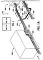
- FIG. 1(in parts FIG. 1A and FIG. 1B ) is a perspective view of a conveying system and a conveyor incorporating certain aspects of the present invention
- FIG. 2is a top view of a filler station and conveyor of the system of FIG. 1 ;
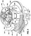
- FIG. 3is a perspective, partial view of the filler station of FIG. 2 without the conveyor links or conveyed objects;
- FIG. 4is a partial end view of the filler station of FIG. 1 showing conveyor links and conveyed objects;
- FIG. 5is a partially broken-apart perspective view of a portion of the filler station of FIG. 1 showing one possible design for an accumulator tank and associated components;
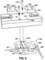
- FIG. 6is an exploded perspective view of one design for a portion of the conveyor of FIG. 1 ;
- FIG. 7is an exploded perspective view of an alternative design for a portion of the conveyor of FIG. 1 ;
- FIG. 8is a bottom perspective view showing one method of engagement between a portion of the conveyor of FIG. 1 and a portion of the filler station;
- FIG. 9is a perspective view of a number of links of the conveyor of FIG. 1 ;
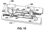
- FIG. 10is a partial perspective view of one possible internal mechanism for a link for a conveyor as in FIG. 1 ;
- FIG. 11is a perspective view of an embodiment of a conveyor according to the present invention, optionally including a drive mechanism and track;
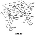
- FIG. 12is a top perspective view of a link of the conveyor of FIG. 11 in a first, opened position
- FIG. 13is a top perspective view of a link of the conveyor of FIG. 11 in a second, closed position
- FIG. 14is a partially exploded bottom perspective view of a link of the conveyor of FIG. 11 ;
- FIG. 15is a bottom perspective view of a link of the conveyor of FIG. 11 holding an object such as a container;
- FIG. 16is a bottom perspective view of a plurality of connected links of the conveyor of FIG. 11 disposed on a track;
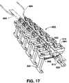
- FIG. 17is a top perspective view of a plurality of connected links of the conveyor of FIG. 11 disposed on a track, and acted upon by a camming rail;
- FIG. 18is a top perspective view of a link for another embodiment
- FIG. 19is a diagrammatical representation of one example of a transfer station including an intermediate gripping conveyor for transferring conveyed articles from a first conveyor to a second conveyor;
- FIG. 20is a perspective view of a portion of another conveyor according to certain aspects of the invention.
- FIG. 21is a top view of a portion of a conveyor as in FIG. 20 ;
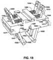
- FIG. 22is a perspective view of a portion of a modified rotary filling machine and modified track ends for use with a conveyor as in FIG. 20 .
- a flexible conveyor having links, and flexible connection elements for conveyors, along with their constituent partsare disclosed. It should be understood that the present invention encompasses both a full conveyor structure made of individual links, connecting structures, and/or other components, and individual components for a conveyor including the connection elements and their components. Other aspects of the invention include the attachment or guidance of the conveyor or its component to links or to mating elements of a processing and/or filling system, as well as elements of a filler. The examples shown herein are for explanatory purposes only, and are not intended to limit the invention only to that shown and disclosed.
- FIGS. 1A–10show embodiments of a flexible conveyor having links, and potential use of such conveyor with a container processing system, including a rotary filler.
- the present inventionincludes various aspects of this complete disclosure.
- FIG. 1(divided into a left-hand section FIG. 1A and a right-hand section FIG. 1B )
- an article conveying system 100is shown.
- system 100may include numerous portions of an article conveying system, such as a system for filling containers.
- FIG. 1may include numerous portions of an article conveying system, such as a system for filling containers.
- system 100may include an accumulator 200 having an accumulator infeed conveyor 202 and an accumulator outfeed conveyor 204 .
- a transfer station 300may be provided for transferring containers C from accumulator outfeed conveyor 204 to main conveyor 400 .
- transfer station 300may include a conventional screw mechanism 302 for spacing containers C so that the containers are in registry with links 410 of main conveyor 400 .
- a relatively short top gripping conveyor(not shown in FIG. 1A ), such as is shown in FIGS. 11–18 , may also be used as a part of transfer stations 300 and 800 to assist in transferring containers from conveyor 204 to conveyor 400 .
- a rinsing station 500is also provided including two inverter mechanisms 502 and 504 .
- Filler station 600is provided including a rotary filler 602 . Downstream of filler station 600 is an additional processing station 700 , which may be a capping station, labeling station, or the like. Finally, a transfer station 800 is provided downstream of the additional station for transferring containers C from main conveyor 400 to a system outfeed conveyor 802 .
- FIG. 1is one possible example of a conveying system suitable for use with the conveyors of the present invention.
- the systemis a filling system
- various stationscould be added or omitted from the above.
- a molding stationcould be included
- separate capping and labeling stationscould be included
- the rinsing stationcould be omitted
- cartoning or packing stationscould be added, etc.
- the present inventionshould not be considered to be limited to the particular filling system shown in FIG. 1 .
- the inventionhas various utilities with systems that are not filling systems. For example, certain benefits of the invention could be achieved using the disclosed conveyors apart from an actual filling operation to process articles, which may or may not be containers.
- the systemcould be used with an accumulator and rinser for empty containers, or with a capper and cartoner for full containers. Also, other sorts of conventional fillers could be used, and the disclosed conveyors need not be used with the filler for all aspects of the invention. Further, the system need not be used with containers at all, but could be used for conveying other objects.
- conveyor 400which will be described in greater detail below, is shown as passing through rinsing station 500 , filler station 600 , and additional station 700 in a loop. It should be understood that more or fewer stations could be included within such loop.
- Accumulator station 200may comprise a spiral accumulator such as a DYNAC®, available from Hartness International, Inc., or any other available spiral, linear, or other type of accumulator device. It should be understood that use of an accumulator station 200 is not necessary according to all aspects of the invention, but the invention does provide certain benefits when used within a system having an accumulator station. As shown, accumulator station includes infeed conveyor 202 which provides the initial supply of containers to system 100 .
- infeed conveyor 202which provides the initial supply of containers to system 100 .
- Infeed conveyor 202supplies containers from a source S that may comprise a storage or staging apparatus (not shown), or may supply containers more directly from a manufacturing apparatus such as a blow molding machine (not shown). Again, although certain benefits of the invention are provided by linking infeed container 202 to a container manufacturing apparatus, such use is not required according to all aspects of the present invention.
- outfeed conveyor 204receives containers from accumulator station 200 and conveys them to transfer station 300 , where the containers are transferred to main (endless) conveyor 400 . If an accumulator station 202 is not used, infeed conveyor 202 may also be eliminated or merged with outfeed conveyor 204 , so that containers conveyed from source S are passed to transfer station 200 without entry into an accumulator.
- infeed and outfeed conveyors 202 and 204may comprise any type of conventional conveyor, such as a knuckle conveyor attached to a platform member, which may be constructed as set forth in U.S. Pat. No. 6,601,697 or in various other ways.
- a knuckle conveyorinstead of a knuckle conveyor, other types of conveyors, belts, or chains such as roller chains, or roller chains with attachments, could be used for infeed and outfeed conveyors 202 and 204 .
- any of the conveyor designs and options disclosed hereincould be utilized.
- infeed and outfeed conveyors 202 and 204would have side rails or some equivalent structure (not shown) for guiding the conveyed containers.
- gripping conveyorssuch as those disclosed in U.S. patent applications Ser. Nos. 10/712,405, 10/712,406, and 10/712,407, all filed Nov. 13, 2003, and U.S. patent application Ser. No. 10/806,806, filed Mar. 30, 2004, all assigned to the owner of the present application, could also be used for infeed and outfeed conveyors 202 and 204 , if desired. Also, the designs of the above patent applications could also be used or adapted for conveyor 400 , discussed in more detail below.
- Transfer station 300functions to transfer containers from outfeed conveyor 204 to main conveyor 400 .
- Transfer station 300includes a conventional screw mechanism 302 for spacing containers along the conveying direction according to the spacing of further machinery, such as filling elements of filler station 600 , as will be described below.
- the parameters of screw mechanism 302may readily be designed by one skilled in the art so as to space containers “on centers” of rinsing elements used to rinse out the containers, filling elements used to fill the containers, and/or capping elements used to cap the containers, if desired.
- Screw mechanism 302may comprise one or more screws, available from Morrison Timing Screws, or any other conventional screw mechanism.
- a top gripping conveyorsuch as is shown in FIGS.
- 11–18may be added to that shown in FIG. 1A to assist in smoothly transferring conveyed objects from an upstream conveyor to a downstream conveyor near screw mechanism 302 . (See FIG. 19 .) Also, it would be possible to place transfer station 300 at the exit to accumulator station 200 and/or infeed conveyor 202 and/or adjacent source S, so as to convey containers more directly to main conveyor 400 , if desired.
- Rinsing station 500as diagrammatically shown includes an inverter 502 , a rinsing device 506 , and an un-inverter 504 .
- Main conveyor 400holds containers as they travel through these elements of the system.
- Main conveyor 400may be a gripping conveyor as disclosed in U.S. patent applications Ser. Nos. 10/712,405, 10/712,406, and 10/712,407, all filed Nov. 13, 2003, and U.S. patent application Ser. No. 10/809,806, filed Mar. 30, 2004, all assigned to the owner of the present application.
- Main conveyor 400is configured so that gripping members may positively grip containers in a fixed position along the conveying direction, spaced “on centers.”
- inverter 502 and un-inverter 504are tracks that spiral through 180 degrees perpendicular to the conveying direction, to alter the orientation of the conveyed containers for rinsing or filling.
- inverter 502 and un-inverter 504could invert the containers by passing main conveyor 400 around an arc along the conveying direction, such as in a high-in/low-out rinser, or a low-in/high-out rinser, as is shown.
- filler station 600may include a rotary filler such as filler 602 .
- a rotary fillersuch as filler 602 .
- the machine 602 and associated methodare not limited to filling of any particular size or shape of container C.
- the containers Care illustrated in the figures as conventional long-necked bottles for purposes of illustration only.
- the filler 602is particularly useful and well-adapted for filling various size and shape containers with relatively little reconfiguration of the machine.
- FIGS. 1A and 1Bfor ease of illustration, a single main conveyor 400 is shown. However, as is made clear in other figures, two or more such conveyors may be utilized with filler 602 . Thus, conveyor 400 a (see FIG. 2 ) has been omitted from FIGS. 1A and 1B . If two main conveyors 400 , 400 a were used, additional corresponding parts of system 100 could also be doubled.
- Filler 602includes a rotating platform, generally 604 having an in-feed section 606 and an out-feed section 608 .
- containers Care transferred via main conveyor 400 onto the rotating platform 604 .
- filled containers Care transferred from the rotating platform 604 via main conveyor 400 .
- containers Cdo not leave conveyor 400 during filling; rather conveyor 400 is connected to and detached from platform 604 for filling.
- the rotating platform 604is a generally circular rotating plate member, as particularly illustrated in FIG. 2 .
- the rotating platform 604rotates about a vertical axis 610 ( FIG. 3 ).
- an on-ramp 612may be disposed at the in-feed 606 section to move conveyor 400 onto the rotating platform 604
- an off-ramp 614may be disposed at the outfeed section 608 to move the conveyor off the rotating platform.
- rotating platform 604may be replaced by a circular portion of conveyor 400 including an extending circular track portion.
- platform 604could have different shapes. It should be appreciated by those skilled in the art that various configurations of conveying systems may be utilized for practicing the invention, and that all such configurations are within the scope and spirit of the invention.
- a filling turret 616is disposed generally above the rotating platform 604 and rotates relative to the vertical axis 610 at a rotational speed that corresponds generally to that of the rotating platform 604 .
- the rotating turret 616 and platform 604may be driven by a common drive mechanism, as described in greater detail below.
- the filling turret 616includes a plurality of radially disposed filling heads, generally 618 , that are movable from a rest position relative to the containers C to a filling position wherein filling elements 620 engage with the containers C for a filling operation (see FIG. 4 ).
- the filling heads 618may be individually supplied and controlled.
- the filling heads 618are configured with respective groups of filling elements 620 .
- Each filling head 618includes an accumulator tank 622 in which a grouping of individual filling elements 620 are configured.
- Each accumulator tank 622is in communication with a rotary gland 624 via flexible coupling hoses 626 .
- Gland 624is connected to a supply pipe 625 , which is in turn in communication with central reservoir R (see FIG. 4 ).
- the individual filling elements 620 in this particular embodimentare arranged in curved, parallel serial rows wherein the outer radial row contains a greater number of elements 620 as compared to the inner radial row. It should be appreciated that the number of elements in each of the rows will be a function of the circumferential spacing and size of the elements, as well as the radial placement of the elements 620 with respect to the axis 610 .
- FIGS. 1A and 1Bonly a single main conveyor 400 is shown. However, as indicated in the figures two such conveyors 400 , 400 a may be used if desired.
- Use of two main conveyorsallows for nearly doubling the processing speed through the system without drastic change in diameter of filler 602 , and allows for double row filling in the filler station 600 .
- a much smaller amount of floor spacecan be used to fill containers, as compared to two separate, side-by-side single file filler stations 600 .
- a double file filler stationis not required for all aspects of the present invention.
- links 412are deleted about filler 602 so that the ramps 612 and 614 , and the holes 628 , and the registration of holes 628 , containers C, and elements 620 can be better illustrated.
- individual filling heads 618can be raised and lowered by way of a rotary track 630 having a follower 632 riding in a groove 634 .
- Interface 636 attached to follower 632rides up and down on member 638 .
- motorized, electronic, hydraulic elementssuch as cylinder 617
- similar elementssuch as cylinder 619
- a motor 640powers rotation of the platform 604 and associated elements around axis 610 .
- motor 640Various user-operated motor controls, such as Allen Bradley programmable logic controllers (not shown) as is known can be provided for motor 640 .
- an on-board computer or other controller 623may be provided either rotationally mounted on platform 604 , as shown in FIG. 3 , or non-rotationally mounted to another portion of filler 602 . Suitable electrical connections would also be provided, depending on the mounting position.
- Other conventional filler head moving mechanismscould also be used in conjunction with the disclosed rotating platform and main conveyor and associated elements, if desired. Thus, any and all such subject matter should be considered within the scope of the present invention.
- FIG. 5shows a diagrammatical (not to scale) example of elements within and attached to a given head 618 .
- interface 636includes rollers 642 that roll along contact member 638 as the interface rises and falls.
- Two pair of rollers 642may be provided, although only one of each pair is shown in FIG. 5 for clarity.
- Two pivoting mounting arms 644are provided on a radially outer portion of interface 636 for receiving an extending tab 646 extending from a radially inner portion of tank 622 .
- Tab 646slides into a mating opening 647 in interface 636 to mount head 618 to the interface.
- Tab 646has slots in it sized for receiving mounting arms 644 so as to prevent tab 646 from withdrawing from opening 647 once mounted.
- Other mating or interlocking structuresmay also be used, if desired, for releasably securing head 618 to interface 636 .
- Use of tab 646 and arms 644allows for quick removal of an entire head 618 when desired.
- FIG. 5further shows a single filling element 620 mounted to bottom wall 622 a of tank 622 via opening 622 b .
- Two openings 622 b and 622 care shown in a single row, although two or more rows of such openings could be provided for filling elements, if desired.
- Filling element 620includes a body 648 mounted to wall 622 a via a mounting clamp 650 , which may be attached via a screw, pin, or the like to wall 622 a .
- a sealsuch as an O-ring 652 is provided between wall 622 a and body 648 .
- a vent tube 654is fixed to body 648 via a seal member 656 .
- a fill tube 658is slidably mounted around vent tube 654 , and is urged downward (as shown) by a spring member 660 .
- a first seal member 662is attached to a bottom portion of fill tube 658
- a second seal member 664is attached to a bottom portion of vent tube 654 .
- Second seal member 664acts to evenly spread liquids within container C during filling.
- Fill tube 658may have a screen (not shown) disposed therein for further improving flow and retaining fluids when desired due to liquid surface tension.
- a centering cup 666may be slidably mounted to body 648 for guiding container necks to contact seal member 662 for filling, as described below.
- Centering cup 666may have one or more guide slots 668 for receiving an extension 670 from body 648 for guiding motion of the centering cup. Although not illustrated as such in FIG. 5 for purposes of clarity, centering cup 666 may simply hang on body 648 under the force of gravity unless lifted by contact due to interaction with a container, but spring loading is also possible.
- filling head 618when no container is present, filling head 618 is at a raised position and fill tube 658 is at a lowered position so that seal members 662 and 664 are in contact, thereby preventing flow of liquid out of filling element 620 through seal member 662 .
- seal member 662eventually comes into contact with the top of a container C.
- Centering cup 666may contact container C during this process to assist in alignment.
- head 618drops further, it lifts sealing member 662 enough so that liquid in tank 622 may follow arrows 672 into container C.
- Fillingmay be accomplished by gravity fill, or with pressurized assistance if desired, with gasses being evacuated from container C substantially through vent tube 654 .
- evacuation of gas from the containereffectively ceases, since liquid flow though fill tube 658 precludes most gas flow out of the container in that route.
- the containermay be filled before filling head 618 is lifted so as to disengage the container.
- Disclosed filling element 620is a reliable gravity fill design that is easy to install and change out when desired. But it should be understood that various commercially available filling elements could be substituted for some aspects of the present invention.
- FIG. 5An example of tank fill and venting systems are also schematically shown in FIG. 5 .
- a release valve or vent 674is shown on an upper wall 622 d of tank 622 .
- a float 676 with an attached positioning rod 678 and position indicator 680are also provided. Float 676 rises or falls with the level of fluid in tank 622 .
- a pneumatic or hydraulic valve 682 actuated by indicator 680controls flow though fluid input line 684 and output line 686 .
- Another pneumatic valve 688controls flow of liquid into tank 622 through hose 626 .
- valve 688is also actuated, thereby causing fluid to flow into tank 622 and evacuated gas to exit through release valve 674 .
- Quick disconnect fittingsmay be used with hose 626 and lines 684 and 686 to improve the ease of changing filling heads, if desired.
- Various other tank filling systemscould alternatively be employed, including electronic sensors and valves, servomotors, etc. However, for such a wet system, use of the mechanical and pneumatic systems may avoid certain environmental issues with electronic parts and controls.
- tank 622 and related filling elements 620may be modified from that shown, for example as set forth in U.S. patent application Ser. Nos. 10/650,490 and 10/274,656, filed Aug. 28, 2003 and Oct. 21, 2002, respectively, for some aspects of the present invention.
- tank 622may include one or more radial or circumferential partitions (not shown) creating distinct portions, with a separate liquid in each portion. Therefore, more than one type of liquid could be put into containers by one tank 622 .
- an inner row of elements 620could fill containers with one liquid on an inner conveyor and an outer row of elements could fill containers with another liquid on an outer conveyor.
- multiple hoses 626 and associated tank filling systemswould be needed in such case.
- individual filling heads 618dispense different liquids as well, and any number of individual heads could be used around filler 602 .
- the filling heads 618are readily removable and replaceable by detaching the hose 626 and lines 684 and 686 , opening arms 644 , and then sliding tab 646 out of opening 647 . At this point another filling head may be connected and filling continued. The removed filling head 618 may be cleaned apart from the filler while the new head is operating on the filler, substantially reducing down time for the filler.
- filling head 618expandable or contractible, by adding or removing any number of filling elements 620 (and plugging the resulting openings).
- filler 602could be modified between a one or two conveyor 400 and/or 400 a system, with one or two liquids, as desired, with minimal modification to individual heads 618 . Also, such modification could be accomplished by switching out whole filler heads 618 , if spare elements are available.
- a single conveyor systemmay include as many as 60–100 individual filling elements 620 .
- the number of elements 620 on filler 602may be increased by about 80%.
- a two-conveyor fillermay achieve rates as high as 150 containers per minute per foot of filler diameter (at heads).
- the corresponding fill rateis on the order of about 1,200 containers per minute. It is expected that using the teachings of the present invention, even higher fill rates are possible in a two-conveyor system.
- Adding a third conveyorwould again increase capacity, perhaps by 60% or more of the single conveyor capacity.
- various aspects of the present conveyor and filler designscan substantially increase filled container output without substantially or correspondingly increasing floor space required for the filler, its various components, and/or associated system components.
- such conveyormay be made of links 412 comprising extending bodies having opposed gripping members 432 and at least one spring member 466 (see FIG. 10 ). At least one of gripping members 432 may move toward the other to grip a container therebetween. Gripping members 432 may include adaptors 492 configured for gripping and centering a container with respect to link 412 , so as to be able to hold container C in a position and registration with a filling element 620 . Cam follower members 452 may be provided for opening gripping members 432 when desired. As shown in FIG.
- gripping members 432may be moved via a double rack and pinion arrangement with pinion 433 mounted for rotation relative to link 412 so as to allow racks 441 to move relative thereto in unison.
- pinion 433mounted for rotation relative to link 412 so as to allow racks 441 to move relative thereto in unison.
- various other designs of main conveyor links in which one or more gripping members 432 are moveablemay be utilized according to the present invention.
- spring members 466urge gripping members 432 toward a closed position.
- the function of cam followers 452 and spring members 466may be reversed so that the cam members urge gripping members 432 toward the closed position and the spring members urge the gripping members toward the open position.
- gripping membersmay contact a conveyed object C to hold the object during transport as the objects pass through the system, including filler station 600 or various other elements.
- Adjacent links 412may be connected via connection elements such as a connecting member 401 (see FIGS. 6 and 9 ).
- connecting member 401includes a braided wire cable 403 made of stainless steel or any other suitable material, or the like with mounting members 405 secured to it at given intervals.
- the mounting members 405may comprise cylindrical swages may of aluminum, stainless steel or any other suitable material or the like secured to cable 403 by a set screw, swaging, welding, braising, or any other reliable manner of attachment.
- connection elementsmay be connected directly to the link bodies 412 or, as shown in FIGS. 6 , 7 and 9 , the connection elements may be connected to an intermediate member 412 a .
- Link bodies 412are then connected to intermediate members 412 a via screws 413 , or any other method of attachment.
- intermediate members 412 amay be removably attachable to links 412 for purposes of quick change out of main conveyor 400 , maintenance, replacement, cleaning, etc.
- intermediate member 412 acould simply comprise an extension disposed at the bottom of link 412 .
- intermediate members 412 amay comprise substantially cylindrical pucks, and the intermediate members include structure for guiding links 412 along a track.
- Intermediate members 412 a in FIG. 6include slots 417 having flared edges 417 a for guiding links 412 along a track (such as on ramps and off ramps 612 and 614 having extending opposed rails).
- Other shapes for the track and the structure for following the trackare possible within the scope of the invention.
- Flared edges 417 aallow for a certain amount of twisting if the tracks are to be inverted, for example as would be done at inverter 502 and inverter 504 , discussed above.
- Links 412may thus follow a track to on ramp 612 (on ramp 612 may even be considered a part of the track), at which point links 412 depart the track and attach themselves to rotatable platform 604 while still holding containers C to be filled. After containers C are filled, links 412 disattach themselves from rotatable platform 604 and rejoin the track, by way of off ramp 614 . Therefore, links 412 include attaching structure for attaching the links to at least one element along the handling or filling system, in this case the filler 602 .
- such attaching structuremay include cooperating elements disposed on each link 412 and on the filler 602 .
- rotating platform 604is shown in dotted lines, even though the rotating platform is below the intermediate member.
- the cooperating elementsmay include an arm 419 (or securing tab) attached to each link 412 and a plurality of openings 628 disposed on rotating platform 604 of filler 602 .
- Arm 419may or may not be utilized to assist in conveyor 400 following any track portion of the system.
- arm 419may include a slanted portion 419 a for guiding arm 419 into hole 628 and includes a cantilevered portion 419 b for securing arm 419 to platform 604 .
- itmay be desirable to include a curvature in the vertical direction along on ramp 612 to guide arm 419 downward into engagement with opening 628 .
- Tension caused by connection element 401pulls arm 419 radially inward (relative to axis 610 ) thereby sliding portion 419 b under the bottom of platform 604 adjacent hole 628 (see arrow A in FIG. 7 ).
- off ramp 614engages links 412 to slide them outward radially (in the direction opposite arrow A in FIG. 7 ) to move part 419 b so as to align with hole 628 , and then links 412 move arm 419 upward out of hole 628 .
- Link 412may then be conveyed downstream of filler 602 for its next processing step.
- pinscould extend out of platform 604 into bottoms of link 412 or intermediate members 412 a . Any such structure for attaching the conveyor to the platform while the container is gripped is within the scope of the invention. Similarly other such structures could be used at other parts of system 100 , modified for the particular application.
- a robust object handling and/or container filling systemcan be carried out using various elements of the above structure, as needed for the particular application. For example, perhaps only a rinser and filler could be used with a conveyor, with the conveyor conveying gripped containers for handling therein. In any event, fewer conveyors are needed, and more rapid processing may be possible with gripped conveyors. Elaborate star wheel systems for loading loose containers of a conveyor onto a filler can be eliminated, and the incidence of improperly aligned, broken, or missing containers at filler heads can be reduced. Also, lines may be able to run faster, as well, because containers are not likely to fall over while being affirmatively and continuously gripped.
- FIGS. 11–18show another embodiment of a conveyor 910 according to certain other aspects of the invention.
- conveyor 910includes a plurality of connected links 912 for conveying objects such as containers along a direction of transport T.
- Conveyor 910may optionally be used to grip objects spaced from or in contact with conveying surfaces 938 of links 912 ( FIGS. 14 and 15 ).
- Conveyor 910is thus suited to grip and convey bottles by the neck, either upright or inverted, if desired.
- conveyor 910could also carry objects sitting on conveying surface 938 .
- Each link 912has a length L extending across the direction of transport T and a width W extending along the direction of transport T (see FIG. 12 ).
- Each link 912has a body 930 , and may have two opposed gripping members 932 , and at least one spring member 966 .
- Cam follower members 952may be located on one or both of gripping members 932 , which are selectively movable between a first, opened position (as shown in FIG. 12 ) and a second, gripping position (as shown in FIG. 13 ).
- the spring member 966urges the gripping members toward the second, gripping position. Gripping members 932 may thus contact one of the conveyed objects C to hold the object during transport when in the second position (see FIG. 15 ).
- Camming memberssuch as cams or, as shown, rails 984 ( FIG. 17 ) may be provided to move gripping members 932 toward the first, opened position against the force of springs 966 .
- gripping members 932are shown as operating independently, if desired, their motions could be more directly tied by use of interacting circular gears, sliders, rack and pinion arrangements, or the like.
- each link 912may include two pins 933 around which gripping members 932 pivot.
- spring members 966comprise tension springs.
- compression springs located on the opposite side of pins 933could be used, or leaf springs could be substituted as well.
- the spring constant of spring members 966can be selected according to the application to as to be able to securely hold the desired object, whether full or empty, in motion and/or traveling around curves. If desired to achieve a certain result, multiple spring members 966 could also be used.
- gripping members 932may include a flexible adaptor 992 for more securely holding the gripped objects in a particular location relative to link 912 .
- the adaptor 992 or the griping member 932may be shaped so that adjacent containers C may be gripped “on-centers” with a predetermined spacing for interaction with other machinery (see, e.g., FIG. 11 below).
- the size and shape of adaptors 992may be altered to suit the application and/or conveyed objects.
- Links 912 and/or adaptors 992may also be particularly configured to allow gripping members 932 to grip bottlenecks, or to grip objects spaced from the links or with the links inverted, as shown.
- Gripping members 932 on adjacent links 912may be connected via connections elements such as a flexible connecting member 901 ( FIG. 14 ).
- the connection elementsare configured so as to allow three-dimensional movement of a given link relative to an adjacent link.
- three-dimensional movementmeans relative movement between links about three axes: twisting between adjacent links around an axis parallel to the direction of transport, and around two axes perpendicular to the direction of transport (i.e., horizontally and vertically, as oriented in FIG. 11 ). If each link grips and conveys one container, the connection elements may allow twisting of approximately 180° or more per foot of member 901 .
- Flexible connecting member 901may comprise a braided wire cable 903 made of stainless steel, or any other suitable materials or the like, with mounting members 905 secured to it at given intervals.
- Mounting members 905may comprise cylindrical swages, as shown, made of aluminum, stainless steel, or any other suitable material or the like, secured to cable 903 by a set screw, swaging, welding, brazing, or any other reliable manner of attachment. If such a flexible connecting member 901 is used, a groove 907 may be formed in conveying surface 938 of link 912 sized so that cable 903 may be slid into the groove. A retaining portion 909 of groove 907 may be provided to receive mounting member 905 .
- Retaining portion 909may be a widened portion of groove 907 configured for receiving mounting member 905 .
- a retainer 911may be slid over top of mounting member 905 and into a slot 913 in body 912 adjacent groove 907 to retain the mounting member in retaining portion 909 .
- Retainer 911may be a spring-type member having leaf spring type edges if desired to hold it in place.
- a set screw, a pin, etc.may be used to secured mounting member 905 within retaining portion 909 .
- a retainer or the likemay not be needed, as tension and friction caused by the arrangement and travel may be sufficient to hold link 912 in place on flexible connecting member 901 .
- individual links 912may be removed from flexible connecting member 901 for service, repair, cleaning, or changing of conveyed object or application, if desired. While such removable mounting is not necessary for all aspects of the invention, such arrangement may be useful in certain applications.
- conveyor 910may include a track 913 , links 912 being configured to follow the track.
- Track 913may have a T-shaped cross section 915 (see FIG. 11 ), and each link 912 may includes a T-shaped channel 917 for receiving and following the track.
- Conveyor 910may utilize other guides instead of track 913 , if desired, and links 912 would be reconfigured accordingly.
- Conveyor 910may also include a rotatable wheel 919 for contacting the links 912 to direct the links around any curves in track 913 , such as curve 921 shown in FIG. 11 .
- a rotatable wheel 919for contacting the links 912 to direct the links around any curves in track 913 , such as curve 921 shown in FIG. 11 .
- Use of wheel 919reduces friction that would be present between links 912 and track 913 along a curve.
- Such a wheelcould also be utilized in non-curved portions of travel as well.
- track 913could bend laterally or twist along the direction of travel, if desired. In particular, track 913 could invert before bottles pass through a rinser and then turn back upright.
- a drive mechanismmay also be provided for driving links 912 in a given direction.
- the drive mechanismmay comprise a motor and motor control 923 , and at least one driven gear 925 having teeth 927 . Teeth 927 are configured to fit between adjacent links 912 in a rack and pinion arrangement to drive the links. Links 912 may accordingly include side cut outs 912 a configured for receiving teeth 927 of gear 925 .
- the drive mechanismmay include two of the driven gears 925 disposed on opposite sides of links 912 , and may also include intermediate gears 929 configured to drive gears 925 at a given speed, as well as other intermediate gearing (not shown) between the output of motor 923 and gears 929 .
- conveyor 910may be readily driven by direct contact with gears 925 .
- gears 925could be replaced with wheels (not shown) that frictionally contact outer ends of links 912 . If so, the wheels could have flexible materials about their edges, and/or links 912 could have similar materials, for a secure frictional engagement so as to reliably drive links 912 .
- FIG. 18shows a link 1012 for a conveyor according to other aspects of the invention.
- the conveyorincludes a plurality of links 1012 each having a body 1030 .
- Four opposed gripping members 1032are provided on each link, in pairs.
- a cam follower member 1052is moveable to selectively move each gripping member 1032 between a first, opened position and a second, gripping position.
- a spring mechanism 1066is provided between each pair of gripping members 1032 .
- Links 1012are similar to links 912 in many ways. However, links 1012 have two pairs of gripping members 1032 per link, rather than one. As above, gripping members 1032 may include flexible adaptors 1092 , which may be made of material such as plastic, rubber, or the like.
- Spring members 1066are compression springs, as above, to urge the gripping members toward the second, closed position.
- a cam member(not shown) may contact each cam follower member 1052 to move gripping members 1032 in the opposite direction.
- the position of the spring member and/or cam membercould be reversed so as to urge gripping members 1032 in opposite directions.
- the compression spring memberscould be replaced with tension springs on the opposite side of pivot pins 1033 , or with leaf springs.
- links 1012could be modified in various other ways, such as by modifying the adaptor 1092 , etc.
- Links 1012may include slots 1017 for receiving a track, which may comprise two opposed rails (not shown). Also, links may include a T-shaped slot 917 , as above. Either way, links 1012 may be guided along the track. As above, links 1012 may be connected via a flexible connector such as a wire cable, or other structures, depending on the application.
- FIGS. 11–18may be utilized in combination with aspects of the designs of FIGS. 1A–10 .
- the conveyors of FIGS. 11–18may be used to grip and convey articles through multiple stations of a processing system, which may include a filler station.
- top gripping conveyor 910may be utilized as part of a transfer station 300 having one or more timing screws 302 , as described above. Therefore, a short top gripping conveyor 910 such as shown in FIGS. 11–18 may be utilized in the system of FIGS.
- Such structurewould be beneficial in aligning the conveyed objects at timing screw 302 while gripped from above so that gripping portions of the downstream conveyor 400 do not interfere with the screw. Then, the top gripping conveyor could pass control to main conveyor 400 , all controlled by simple cams and followers. If a timing screw or other such objects that might be interfered with are not present near the moveable portions of the gripping conveyor, then it may be suitable to simply cam open grippers of the gripping conveyor to directly pass the conveyed articles to the next station, conveyor, etc. However, a combination of a top gripping conveyor and bottom gripping conveyor, in either order, can have various utilities in article handling and container filling.
- conveyors of FIGS. 11–18could be used to grip container bases rather than necks and still be used in the system of FIGS. 1A and 1B . If so, certain modifications would be possible, such as modifications to the track and adding cooperating elements to attach the conveyor links to processing stations such as the filler.
- FIGS. 20–22show another alternate construction of a conveyor, along with certain corresponding system components such as a track, a filler portion, etc.
- FIG. 20shows an alternative track 1113 including dual channels 1115 facing each other.
- An alternate form of intermediate element 1112 ais shown having an extending flange 1117 that slides within channels 1115 .
- No arm, such as arm 419 above,is provided on a bottom surface of intermediate element 1112 a.
- connection element 1101is provided for connecting adjacent intermediate elements 1112 a into a conveyor.
- Links(not shown), such as any of the links discussed above, may be attached in various ways to intermediate elements 1112 a to form a conveyor.
- Connection element 1101comprises a barbell shaped element having a center rod 1103 and two larger end pieces 1105 .
- End pieces 1105comprise spherical members that are seated within openings 1109 in intermediate elements 1112 a .
- Slots 1107 extending from openings 1109allow for assembly and a certain amount of play between adjacent intermediate elements 1112 a to provide for three-dimensional movement between adjacent intermediate elements 1112 a, as discussed above.
- filler 602includes three rotating platforms 604 a, 604 b, and 604 c .
- Platform 604 ais located vertically lowest and platform 604 c is located vertically highest.
- On ramps 612 a and 612 b (for dual conveyors) and off ramps 612 a and 614 b (also for dual conveyors)are substantially flat and slide intermediate elements 1112 a substantially horizontally onto rotating platforms 604 a and 604 b .
- Platforms 604 b and 604 cinclude receiving elements 628 b in the shape of indentations for receiving sides of intermediate elements 1112 a .
- conveyorsare fed to filler 600 along tracks (not shown other than the on and off ramps), at which point the conveyors depart the tracks and are gripped by the filler in registration with filling heads (not shown in FIG. 22 ).
- Each indentation 628 bis disposed for placing a conveyed container in registration with a filler element.
- intermediate elements 1112 acould include indentations and platforms 604 a–c could include mating protrusions, or other equivalent cooperating structures.
- connection elements 1101Tension between adjacent links caused by the connection of connection elements 1101 keeps the links tightly held against indentations 628 b for conveying containers around the filler for filling.
- Use of the intermediate elements 1112 aallows for the direct sliding (without any vertical component) to place links in location for filling containers, as contrasted with use of intermediate elements 412 a having arm 419 . In certain situations such structure could provide beneficial results in terms of container stability. Again, such structure need not be used in a dual filler configuration, at which point elements 612 b, 614 b and 604 c could be eliminated. Numerous modifications and variations are possible for the device of FIGS. 20 and 21 , incorporating various of the teachings of previous figures and embodiments.
- the conveyors and links of FIGS. 1A–22have particular usefulness in picking up and moving objects including containers, either by their necks or their bases.
- the objectscan be inverted, if desired, to pass them through a rinser or a labeler, or to allow them to drain.
- Moving lightweight plastic containersis also reliably performed, as the bottles are securely gripped during travel. Tipping over of such lightweight containers is not an issue when the containers are gripped from above. Therefore, it is possible in some applications to move the conveyed objects very rapidly.
- each linkmay include only one or multiple gripping members.
- Each gripping membermay include only one or multiple gripping arms.
- gripping armsmay be actuated by a single slider on a link, or each gripping arms may be actuated by a single slider on a link, or each gripping arm may have its own slider.
- the shape of the link body, the method of attachment to the drive mechanism, the type of drive mechanism, and the disclosed uses of the conveyors hereinare also examples only, and no limitations should be drawn from this disclosure. Thus, the present invention contemplates that any and all such subject matter is included within the scope of the present invention.
Landscapes
- Engineering & Computer Science (AREA)
- Mechanical Engineering (AREA)
- Filling Of Jars Or Cans And Processes For Cleaning And Sealing Jars (AREA)
- Specific Conveyance Elements (AREA)
Abstract
Description
Claims (54)
Priority Applications (2)
| Application Number | Priority Date | Filing Date | Title |
|---|---|---|---|
| US10/880,351US7299832B2 (en) | 2004-06-29 | 2004-06-29 | Rotary filling machine and related components, and related method |
| PCT/US2004/037107WO2006011894A1 (en) | 2004-06-29 | 2004-11-05 | Rotary filling machine and method of filling containers using a rotary filling machine |
Applications Claiming Priority (1)
| Application Number | Priority Date | Filing Date | Title |
|---|---|---|---|
| US10/880,351US7299832B2 (en) | 2004-06-29 | 2004-06-29 | Rotary filling machine and related components, and related method |
Publications (2)
| Publication Number | Publication Date |
|---|---|
| US20050284537A1 US20050284537A1 (en) | 2005-12-29 |
| US7299832B2true US7299832B2 (en) | 2007-11-27 |
Family
ID=34959448
Family Applications (1)
| Application Number | Title | Priority Date | Filing Date |
|---|---|---|---|
| US10/880,351Expired - LifetimeUS7299832B2 (en) | 2004-06-29 | 2004-06-29 | Rotary filling machine and related components, and related method |
Country Status (2)
| Country | Link |
|---|---|
| US (1) | US7299832B2 (en) |
| WO (1) | WO2006011894A1 (en) |
Cited By (24)
| Publication number | Priority date | Publication date | Assignee | Title |
|---|---|---|---|---|
| US20070209328A1 (en)* | 2005-12-23 | 2007-09-13 | The Coca-Cola Company | Apparatus and Method for Orienting Spheroidal Containers and Packaging Beverages in Spheroidal Containers |
| US20080142336A1 (en)* | 2004-02-02 | 2008-06-19 | Krones Ag | Device for Dynamic Storage of Objects |
| US20080314476A1 (en)* | 2004-08-21 | 2008-12-25 | Herbert Bernhard | Beverage bottling plant for filling bottles with a liquid beverage material |
| US20090071569A1 (en)* | 2006-03-24 | 2009-03-19 | Thomas Stienen | Beverage bottling plant for filling bottles with a liquid beverage, having a flow meter integrated into the filling element and located in the flow path for filling bottles with a liquid beverage and a filling machine having such a filling element |
| US20090200136A1 (en)* | 2006-02-20 | 2009-08-13 | Krones Ag | Device for storing objects |
| US20100037981A1 (en)* | 2008-08-13 | 2010-02-18 | Uhlmann Pac-Systeme Gmbh & Co.Kg | Method and device for filling containers |
| US20100044185A1 (en)* | 2006-07-29 | 2010-02-25 | Krones Ag | Conveying Device |
| US20100224283A1 (en)* | 2006-02-14 | 2010-09-09 | Azionaria Costruzioni Macchine Automatiche A.C.M.A. S.P.A. | Carousel for Processing Containers Filled With Liquid or Powder Products |
| US20100314223A1 (en)* | 2006-03-16 | 2010-12-16 | Krones Ag | Conveyance means |
| US7926642B2 (en) | 2004-10-16 | 2011-04-19 | Krones Ag | Device for the buffering of objects |
| US8162127B2 (en) | 2005-08-27 | 2012-04-24 | Krones Ag | Dynamic storage for objects |
| US20140069054A1 (en)* | 2012-09-09 | 2014-03-13 | Multivac Sepp Haggenmuller Gmbh & Co. Kg | Tray sealer |
| US9067773B2 (en) | 2010-09-10 | 2015-06-30 | Pepsico, Inc. | Prevention of agglomeration of particles during sterilization processes |
| US9120587B2 (en) | 2010-09-10 | 2015-09-01 | Pepsico, Inc. | In-package non-ionizing electromagnetic radiation sterilization |
| US20160152413A1 (en)* | 2014-11-28 | 2016-06-02 | Samsung Electronics Co., Ltd. | Conveyor apparatus |
| US20160244310A1 (en)* | 2015-02-24 | 2016-08-25 | G.D Societa' Per Azioni | Filling Apparatus for Filling Containers and Related Method |
| US20170001848A1 (en)* | 2015-06-23 | 2017-01-05 | World Packaging Company, Inc. | Multi-container filling machine, valves, and related technologies |
| USD821133S1 (en) | 2016-06-23 | 2018-06-26 | Abc Fillers, Inc. | Multi-container filling nozzle |
| US20180346306A1 (en)* | 2017-06-06 | 2018-12-06 | Promach Filling Systems, Llc | Rotary filling machine |
| US10507158B2 (en) | 2016-02-18 | 2019-12-17 | Hill-Rom Services, Inc. | Patient support apparatus having an integrated limb compression device |
| US11891206B2 (en)* | 2017-06-29 | 2024-02-06 | G.D S.P.A. | System for assembling and filling two groups of electronic cigarettes |
| US11897747B1 (en) | 2019-03-27 | 2024-02-13 | Abc Fillers, Inc. | Multi-container filling machine technologies |
| US12275627B2 (en)* | 2022-09-12 | 2025-04-15 | Gruppo Bertolaso S.P.A. | Filling valve group for a filling machine |
| US12415714B2 (en) | 2019-03-27 | 2025-09-16 | Abc Fillers, Inc. | Multi-container filling machine technologies |
Families Citing this family (18)
| Publication number | Priority date | Publication date | Assignee | Title |
|---|---|---|---|---|
| US7278531B2 (en) | 2004-06-29 | 2007-10-09 | Hartness International, Inc. | Flexible conveyor and connection elements |
| US7299832B2 (en) | 2004-06-29 | 2007-11-27 | Hartness International, Inc. | Rotary filling machine and related components, and related method |
| US7331156B2 (en) | 2004-06-29 | 2008-02-19 | Hartness International, Inc. | System for securely conveying articles and related components |
| DE102006033111A1 (en)* | 2006-07-18 | 2008-01-31 | Khs Ag | treatment machine |
| EP2094600B2 (en)* | 2006-10-24 | 2022-05-18 | KHS GmbH | Filling machine |
| CN102485598A (en)* | 2010-12-04 | 2012-06-06 | 大连渴望科技发展有限公司 | Fruit/vegetable filling device |
| US9790074B2 (en)* | 2013-02-25 | 2017-10-17 | Khs Gmbh | Filling system |
| PL3119678T3 (en)* | 2014-03-21 | 2019-03-29 | G.D Societa' Per Azioni | Machine and method for producing electronic-cigarette cartridges |
| CN105036036A (en)* | 2015-07-24 | 2015-11-11 | 镇江市顶智微电子科技有限公司 | Method for rinsing, screening, conveying, filling and sealing pharmaceutical chemical biological reagent bottles and conveying bottle covers |
| CN109690430B (en) | 2016-09-09 | 2022-06-24 | 宝洁公司 | System and method for producing products based on demand |
| US11584628B2 (en) | 2016-09-09 | 2023-02-21 | The Procter & Gamble Company | System and method for independently routing vehicles and delivering containers and closures to unit operation systems |
| WO2018049119A1 (en)* | 2016-09-09 | 2018-03-15 | The Procter & Gamble Company | Methods for simultaneously producing different products on a single production line |
| CN108131560B (en)* | 2017-12-26 | 2023-12-26 | 洛阳理工学院 | Automatic filling production line of circulating liquefied gas steel cylinder |
| EP3823479A1 (en)* | 2018-07-19 | 2021-05-26 | Sluis Cigar Machinery B.V. | Processing line comprising processing modules for performing processing operations on a product or part thereof, and simulated smoking device manufacturing line |
| CN109466835B (en)* | 2018-11-09 | 2023-12-15 | 广州达意隆包装机械股份有限公司 | Rotary filling machine |
| DE102019113653A1 (en) | 2019-05-22 | 2020-11-26 | Krones Ag | Device for holding a container and closing device |
| US10994879B2 (en)* | 2019-09-20 | 2021-05-04 | Spee-Dee Packaging Machinery, Inc. | Rotary filling machine |
| USD1045605S1 (en) | 2020-04-16 | 2024-10-08 | Ez Pour, Llc | Combination sleeve receiver and collapsible flexible accordion spout for a container |
Citations (300)
| Publication number | Priority date | Publication date | Assignee | Title |
|---|---|---|---|---|
| US766329A (en) | 1903-05-08 | 1904-08-02 | James Cunning | Multiple-can-filling machine. |
| US989546A (en) | 1907-06-13 | 1911-04-11 | Mathias Jensen | Bottle-filling machine. |
| US1058096A (en) | 1911-12-09 | 1913-04-08 | Frank Gebbie | Can-filling machine. |
| US1072290A (en) | 1910-05-06 | 1913-09-02 | Dairymens Supply Company | Bottle-filling machine. |
| US1073067A (en) | 1912-04-24 | 1913-09-09 | Ayars Machine Co | Can-filling machine. |
| US1481259A (en) | 1923-01-19 | 1924-01-22 | James E Harrison | Fishing tool |
| US1538406A (en) | 1924-06-19 | 1925-05-19 | Chalmer D Mccarty | Well-fishing tool |
| US1583767A (en) | 1925-10-21 | 1926-05-11 | Merrill I Akins | Fishing tool |
| US1636421A (en) | 1925-08-10 | 1927-07-19 | Warren E Knott | Chuck |
| US1883007A (en) | 1930-05-10 | 1932-10-18 | Western Electric Co | Conveyer |
| US1892463A (en) | 1927-06-03 | 1932-12-27 | Corning Glass Works | Glass working machine |
| US1933551A (en) | 1931-02-05 | 1933-11-07 | Horix Mfg Company | Bottle capping attachment |
| US1942885A (en) | 1925-12-26 | 1934-01-09 | Standard Cap & Seal Corp | Bottle capping machine |
| GB513260A (en) | 1938-03-04 | 1939-10-09 | Herbert Cyril Taylor | Apparatus for filling and/or applying closures to bottles or other containers |
| US2258717A (en) | 1939-08-07 | 1941-10-14 | Dostal & Lowey Co Inc | Bottle carrier for bottle washing machines |
| US2270709A (en) | 1940-05-25 | 1942-01-20 | Pittaluga Stefano | Fruit and vegetable juice filling machine |
| US2277688A (en) | 1938-07-08 | 1942-03-31 | Edward Ermold Co | Packaging machine |
| US2350692A (en) | 1943-12-28 | 1944-06-06 | Alexander Healy Jr | Fishing tool |
| US2611524A (en) | 1947-11-25 | 1952-09-23 | Baltimore Biolog Lab | Apparatus for filling ampoules |
| US2666564A (en) | 1950-03-02 | 1954-01-19 | Pfaudler Co Inc | Filling machine |
| US2671588A (en) | 1948-11-18 | 1954-03-09 | Clarence W Vogt | Paired bag filling machine |
| US2723790A (en)* | 1950-04-05 | 1955-11-15 | Nat Dairy Res Lab Inc | Gas charging machine and method |
| US2730279A (en) | 1951-11-23 | 1956-01-10 | Graham Enock Mfg Company Ltd | Bottle crating and decrating machines |
| US2760316A (en) | 1952-08-12 | 1956-08-28 | Okulitch George Joseph | Automatic case filling machine |
| US2766635A (en) | 1954-10-22 | 1956-10-16 | Lathrop Paulson Co | Conveyor chain |
| US2890553A (en) | 1953-11-16 | 1959-06-16 | Crown Cork & Seal Co | Case filling machine |
| FR1195550A (en) | 1958-05-02 | 1959-11-18 | Materiel D Alimentation Sa Con | Handling chain for packaging installation of products or foodstuffs in various containers |
| US2921425A (en) | 1957-04-04 | 1960-01-19 | Seval Andre Amand Etienne | Very high capacity boxing machine |
| US2928693A (en) | 1956-10-24 | 1960-03-15 | Jr Kenneth F Cannon | Automatic load-release coupler |
| US3012811A (en) | 1960-03-21 | 1961-12-12 | Sandrock Raymond James | Gripping tool |
| US3028713A (en) | 1958-10-02 | 1962-04-10 | Kennedy Edward | Article counting and loading machine |
| US3067863A (en) | 1959-04-21 | 1962-12-11 | Fr Hesser Maschinenfabrik Ag F | Endless conveyor mechanism for folding boxes in packaging machines |
| US3125370A (en) | 1964-03-17 | Self-centering article crimpers | ||
| US3168123A (en) | 1962-01-24 | 1965-02-02 | Pellerino Ernest | Automatic machines for filling bottles, cans and the like |
| US3308928A (en) | 1964-03-18 | 1967-03-14 | Jacob H Mosterd | Apparatus for causing articles separately supplied by grip means to be deposited in a row one after another |
| US3505787A (en) | 1968-03-04 | 1970-04-14 | Lodge & Shipley Co | Case packer |
| US3519108A (en) | 1968-07-11 | 1970-07-07 | Richardson Merrell Inc | Machine for filling bottles |
| US3553932A (en) | 1969-02-05 | 1971-01-12 | Lodge & Shipley Co | Case packer having floating guides |
| US3553927A (en) | 1968-03-13 | 1971-01-12 | Carlos Anglade Jr | Apparatus and method for packing articles in containers |
| US3555773A (en) | 1969-06-23 | 1971-01-19 | Lodge & Shipley Co | Four-head carriage for case packer |
| US3555770A (en) | 1969-01-28 | 1971-01-19 | Lodge & Shipley Co | Case packer |
| US3590982A (en) | 1969-05-19 | 1971-07-06 | Owens Illinois Inc | Article transfer apparatus |
| US3608700A (en) | 1969-12-12 | 1971-09-28 | Kockum Soederhamn Ab | Infeed conveyor |
| GB1264622A (en) | 1968-05-15 | 1972-02-23 | ||
| US3648427A (en) | 1970-08-11 | 1972-03-14 | Emhart Corp | Apparatus for loading frangible containers |
| US3656517A (en) | 1966-10-20 | 1972-04-18 | Perry Ind Inc | Powder filling machine and method |
| US3664491A (en) | 1970-06-11 | 1972-05-23 | Granco Equipment | Conveyor slat construction |
| US3703954A (en) | 1971-03-16 | 1972-11-28 | Artos Engineering Co | Conveyor system for wire like articles |
| GB1301335A (en) | 1970-10-03 | 1972-12-29 | ||
| US3727366A (en) | 1970-10-19 | 1973-04-17 | Fmc Corp | Casing machine |
| US3742989A (en) | 1971-06-14 | 1973-07-03 | R Campbell | Bottle alignment device for bottle filling machines |
| US3747737A (en) | 1971-11-12 | 1973-07-24 | Delamere & Williams Co Ltd | Article handling apparatus |
| US3754637A (en) | 1971-02-12 | 1973-08-28 | Ato Inc | Clamping means for container labeling and strip-applying apparatus |
| US3771284A (en) | 1971-09-20 | 1973-11-13 | Federal Mfg Co | Capping apparatus |
| US3777877A (en) | 1972-10-12 | 1973-12-11 | Stearns Manuf Co Inc | Conveyor assembly |
| US3794315A (en) | 1970-07-17 | 1974-02-26 | Fuji Photo Film Co Ltd | Bag conveyor system with automatic edge pressing |
| US3805476A (en) | 1971-02-25 | 1974-04-23 | Mitsubishi Heavy Ind Ltd | Method and apparatus for encasing of articles |
| US3818785A (en) | 1971-03-27 | 1974-06-25 | Shikoku Kakoki Co Ltd | Bottling system |
| US3825980A (en) | 1972-10-17 | 1974-07-30 | Us Navy | Retaining and release assembly |
| US3826293A (en) | 1973-04-16 | 1974-07-30 | Fmc Corp | No can-no fill for high speed rotary filling machine |
| US3854574A (en) | 1973-05-29 | 1974-12-17 | Rexnord Inc | Luggage dispensing conveyor |
| US3856059A (en) | 1973-03-07 | 1974-12-24 | R Hartness | Container centering device |
| US3858709A (en) | 1970-03-31 | 1975-01-07 | Owens Illinois Inc | Container handling apparatus |
| US3860104A (en) | 1973-04-19 | 1975-01-14 | Indian Head Inc | Bottle conveyor system including adjustable height continuous belt conveyor and positive lock spray shielded rotatable bottle carrier |
| US3864890A (en) | 1973-01-08 | 1975-02-11 | Huntingdon Ind Inc | Bottle packaging machine and method |
| DE2153078C3 (en) | 1971-10-25 | 1975-02-27 | Edwig Dmitriewitsch Nikolajew Glesin | Vertical conveyor |
| US3881592A (en) | 1972-12-29 | 1975-05-06 | Stanray Corp | Modular baggage handling system with chain drive |
| US3910404A (en) | 1973-03-01 | 1975-10-07 | Ulf Henrekson | Conveying means |
| US3938847A (en) | 1972-11-13 | 1976-02-17 | Industrial Automation Corporation | Gripper means |
| US3944058A (en) | 1973-04-19 | 1976-03-16 | Indian Head Inc. | Bottle conveyor system including adjustable height continuous belt conveyor and positive lock spray shielded rotatable bottle carrier |
| US3949859A (en) | 1974-05-30 | 1976-04-13 | Micafil A.G. | Apparatus for grabbing, holding and transporting workpieces on a conveyor chain |
| US3958685A (en) | 1974-06-03 | 1976-05-25 | Cincinnati Milacron, Inc. | Coupling for handling workpiece, conveyor combined therewith, and method |
| US3971190A (en) | 1975-02-20 | 1976-07-27 | A-T-O Inc. | Article transfer apparatus having releasable rods |
| US3990209A (en) | 1973-12-10 | 1976-11-09 | Solbern Corporation | Machine and method for transferring predetermined numbers of items |
| US3992766A (en) | 1975-08-26 | 1976-11-23 | Youngs Rubber Corporation | Apparatus for processing elastic articles |
| US4018325A (en) | 1975-10-09 | 1977-04-19 | The Pillsbury Company | Automatic package accumulator |
| US4033862A (en) | 1976-01-21 | 1977-07-05 | Paper Converting Machine Company | Apparatus for handling wound rolls |
| US4053003A (en)* | 1974-04-15 | 1977-10-11 | The Coca-Cola Company | Machine for filling containers |
| US4055943A (en) | 1976-06-09 | 1977-11-01 | Abc Packaging Machine Corporation | Bottle loading machine |
| US4064987A (en) | 1976-02-12 | 1977-12-27 | Rowan Daniel J | Conveyor system for handling non-rigid containers |
| US4068882A (en) | 1975-11-21 | 1978-01-17 | Staalkat B.V. | Carrier for articles, such as eggs |
| US4096939A (en) | 1976-03-12 | 1978-06-27 | Owens-Illinois, Inc. | Apparatus for feeding glass containers at spaced intervals |
| US4106612A (en) | 1976-09-24 | 1978-08-15 | Mbi Corporation | Gripper for case unloader |
| US4126163A (en) | 1977-02-17 | 1978-11-21 | Hartness Thomas P | Centering device for bottle filling machines |
| US4159762A (en) | 1976-09-10 | 1979-07-03 | Avon Products, Inc. | Article transferring apparatus |
| US4159608A (en)* | 1978-04-28 | 1979-07-03 | Package Engineering Corporation | Bottling machine |
| US4166527A (en) | 1977-08-01 | 1979-09-04 | Stelron Cam Company | Device for picking up and placing articles on movable conveyors and assembly lines and to an endless construction and to an article pickup and deposit device therefor |
| US4169621A (en) | 1977-10-25 | 1979-10-02 | A-T-O, Inc. | Bottle gripping device |
| US4171738A (en) | 1977-08-19 | 1979-10-23 | Glopak Industries Limited | Conveyor mechanism for conveying flexible pouches adapted to contain fluids, granular substances and the like |
| US4172514A (en) | 1977-02-07 | 1979-10-30 | Giddings & Lewis, Inc. | High speed continuous assembly machine |
| US4183428A (en) | 1978-02-21 | 1980-01-15 | A-T-O Inc. | Mounting bar and gripper jaw assembly |
| US4208852A (en) | 1974-11-08 | 1980-06-24 | Pont-A-Mousson S.A. | Process for the aseptic packing of products and machine employing said process |
| US4215521A (en) | 1978-09-07 | 1980-08-05 | Hartness Thomas Signor | Article retarding device for case loading machine |
| US4257727A (en) | 1977-02-28 | 1981-03-24 | Industrial Automation Corp. | Full depth uncaser |
| US4287980A (en) | 1979-09-21 | 1981-09-08 | E. P. Remy Et Cie. | Device for distributing containers into several rows and machine using such a device |
| US4291733A (en) | 1978-06-09 | 1981-09-29 | Stork Repak B.V. | Device for handling containers |
| US4294057A (en) | 1978-04-12 | 1981-10-13 | A-T-O, Inc. | Case packer apparatus including velocity compensator assembly |
| US4300330A (en) | 1979-11-13 | 1981-11-17 | Hartness International, Inc. | Bottle loading machine |
| US4312439A (en) | 1979-12-14 | 1982-01-26 | William P. Young Co. | Machine for applying base cups to bottles |
| US4320914A (en) | 1979-07-27 | 1982-03-23 | Beta Engineering & Development Ltd. | Clamping-type holder |
| JPS5785714U (en) | 1980-11-12 | 1982-05-27 | ||
| US4335761A (en) | 1980-07-21 | 1982-06-22 | Fci, Inc. | Reciprocal bottle filling device |
| JPS57209104A (en) | 1981-06-19 | 1982-12-22 | Daifuku Co Ltd | Tire pinch-holding conveyor |
| US4446672A (en) | 1981-08-31 | 1984-05-08 | Standard-Knapp, Inc. | Method for drop packing small unstable articles |
| US4457121A (en) | 1982-09-27 | 1984-07-03 | Standard-Knapp, Inc. | Continuous motion bottle packer |
| US4467847A (en) | 1981-06-19 | 1984-08-28 | Jagenberg Ag | Machine for labeling and/or filling bottles along two paths |
| US4483436A (en) | 1981-12-04 | 1984-11-20 | The Continental Group, Inc. | Transport pallet |
| US4502587A (en) | 1983-04-18 | 1985-03-05 | R. J. Reynolds Tobacco Company | Automatic accumulator for rectangular articles |
| US4513858A (en) | 1981-05-18 | 1985-04-30 | Mapatent, N.V. | Horizontal accumulator |
| JPS6087111A (en) | 1983-10-17 | 1985-05-16 | Imai Tekkosho:Kk | Conveyer apparatus |
| US4522238A (en) | 1983-02-16 | 1985-06-11 | Elmar Industries, Inc. | Valve control mechanism for reciprocating valves of a positive displacement rotary filling machine |
| US4524865A (en) | 1981-11-06 | 1985-06-25 | Von Hofen Edward L | Universal platform chain |
| US4528796A (en) | 1983-02-08 | 1985-07-16 | E. P. Remy Et Cie | Apparatus for automatic filling and closing of containers |
| US4530433A (en) | 1982-05-18 | 1985-07-23 | Enomec S.R.L. | Bottle-holder pincers forming a link in a conveyor chain |
| US4532968A (en) | 1983-06-23 | 1985-08-06 | The Kartridg Pak Co. | Rotary filling apparatus and method |
| US4533038A (en) | 1977-06-22 | 1985-08-06 | Manufacture De Machines Du Haut-Rhin | Conveyor for objects treated while continuously in motion |
| US4541524A (en) | 1983-03-11 | 1985-09-17 | Figgie International | Case packer |
| US4553442A (en) | 1982-05-18 | 1985-11-19 | Societe Paris-Rhone | Starter for heat engine comprising a reinforced support |
| US4567919A (en) | 1983-09-08 | 1986-02-04 | Fogg Filler Company | Container filling machine and process |
| US4585369A (en) | 1983-12-01 | 1986-04-29 | Alsthom-Atlantique | Mechanical connection means |
| US4587792A (en) | 1984-08-06 | 1986-05-13 | Hartness International, Inc. | Apparatus for opening box flaps on an article loading machine |
| US4588001A (en) | 1983-06-23 | 1986-05-13 | The Kartridg Pak Co. | Rotary filling apparatus and method |
| US4638906A (en) | 1985-11-19 | 1987-01-27 | Harris Graphics Corporation | Conveyor assembly |
| US4655029A (en) | 1984-10-31 | 1987-04-07 | Krones Ag Herman Kronseder Maschinenfabrik | Method and apparatus for filling bottles or the like with liquid |
| US4678077A (en) | 1984-12-07 | 1987-07-07 | Rotomors S.P.A | System for controlling the jaws of a self-centering platform (pallet) which can be moved between fittings (pallet supports) carried by the loading and unloading station and the working station of a machine tool |
| US4697691A (en) | 1985-02-11 | 1987-10-06 | Jagenberg Aktiengesellschaft | Apparatus for transferring articles, especially bottles |
| US4723906A (en) | 1986-06-02 | 1988-02-09 | Cincinnati Milacron Inc. | Blow molding apparatus |
| US4723649A (en) | 1986-07-21 | 1988-02-09 | Hartness International | Apparatus for aligning articles in parallel rows |
| US4746007A (en) | 1986-02-20 | 1988-05-24 | Quipp Incorporated | Single gripper conveyor system |
| US4790421A (en) | 1987-10-22 | 1988-12-13 | The Boeing Company | Roller assembly |
| US4793261A (en) | 1987-02-11 | 1988-12-27 | Durr Industries, Inc. | Accumulating pallet chain-dog conveyor and method of conveying pallets |
| US4807421A (en) | 1985-07-19 | 1989-02-28 | Mitsubishi Jukogyo Kabushiki Kaisha | Equipment for handling various containers |
| US4817780A (en) | 1984-07-23 | 1989-04-04 | Davidsson Mats I | Means for securing objects |
| US4823934A (en) | 1986-12-01 | 1989-04-25 | E. P. Remy & Cie. | Device for gripping and holding back articles, such as for example containers, on a conveyor, and conveyor equipped with this device |
| US4835946A (en) | 1987-01-28 | 1989-06-06 | Hartness International | Article transport apparatus |
| US4856144A (en) | 1986-11-17 | 1989-08-15 | Terpa Poultry B.V. | Method and an apparatus for transporting slaughter animals during slaughtering, packaging or otherwise processing said animals, in particular poultry |
| US4878577A (en) | 1986-11-04 | 1989-11-07 | Investronica, S.A. | Peg for overhead trouser conveyor |
| US4888936A (en) | 1985-11-28 | 1989-12-26 | The Coca-Cola Company | Apparatus for producing bottled beverages |
| US4901844A (en) | 1988-10-03 | 1990-02-20 | Kvp Systems, Inc. | Low tension plastic conveyor belt system |
| US4921294A (en) | 1988-06-03 | 1990-05-01 | Am International Incorporated | Spring wire gripper jaw |
| EP0366067A1 (en) | 1988-10-24 | 1990-05-02 | Fmc Corporation | Container filler and sealer with two directional flexing chain |
| US4925013A (en) | 1984-08-20 | 1990-05-15 | The Laitram Corporation | Conveyor belt having a high friction conveying surface |
| US4934517A (en) | 1988-11-14 | 1990-06-19 | The Laitram Corporation | Horizontal flexing conveyor belt |
| US4953687A (en) | 1987-09-22 | 1990-09-04 | Solis S.R.L. | Method and apparatus for automatically transferring and accumulating groups of flaccid articles |
| US5004097A (en) | 1990-01-30 | 1991-04-02 | Ashworth Bros., Inc. | Replaceable snap-on modular overlay for rod and link turn-curve conveyor belts |
| US5029695A (en) | 1990-04-03 | 1991-07-09 | S. C. Johnson & Son, Inc. | Improved starwheel |
| US5035270A (en) | 1989-11-08 | 1991-07-30 | Herzog Kenneth J | Automatic conveyorized container filler |
| US5052166A (en) | 1989-05-24 | 1991-10-01 | Sig Schweizerische Industrie-Gesellschaft | Method and apparatus for continuous package making |
| US5072573A (en) | 1990-01-12 | 1991-12-17 | Tisma Machine Corporation | Apparatus with adjustable width trays for automatic packaging machines |
| US5074103A (en) | 1990-10-23 | 1991-12-24 | Dowell International Packaging Systems, Inc. | Bottle loading machine and method |
| EP0471401A2 (en) | 1990-08-06 | 1992-02-19 | Gerardus Smit | Apparatus for selectively separating a bottle from a stream of bottles |
| US5115901A (en) | 1988-06-27 | 1992-05-26 | Axis U.S.A., Inc. | Automatic adjustment of pallet workpiece support members |
| US5127514A (en) | 1991-09-10 | 1992-07-07 | Peter Guttinger | Variable width conveyor bucket |
| US5170546A (en) | 1992-02-21 | 1992-12-15 | Overton Corporation | Indexing machine with rotary cam drive |
| US5174430A (en) | 1990-10-11 | 1992-12-29 | Tetra Alfa Holdings Sa | Distributing and collecting device for conveyed products |
| US5212930A (en) | 1991-11-26 | 1993-05-25 | Standard-Knapp, Inc. | Continuous motion packer for loading parallel columns of upright containers into partitioned packing cases |
| US5219405A (en) | 1987-12-16 | 1993-06-15 | Krones Ag Hermann Kronseder Maschinenfabrik | Continuously operating rotational bottle filling installation |
| US5219065A (en) | 1984-05-25 | 1993-06-15 | Rexnord Corporation | Chain link for a product capturing chain |
| US5257888A (en) | 1990-11-13 | 1993-11-02 | Hermann Kronseder | Apparatus for crating and uncrating containers |
| DE4216721A1 (en) | 1992-05-20 | 1993-11-25 | Kettner Verpackungsmaschf | Packing system for moving bottles and cans in and out of crates - has conveyor system for crates following circulating path of grippers which pick up and put down bottles. |
| US5285884A (en) | 1990-12-22 | 1994-02-15 | Bernhard Beumer Maschinenfabrik Kg | Tipping conveyor element |
| US5295523A (en) | 1992-04-09 | 1994-03-22 | Aliseo Gentile | Adjustable stroke multiple package filling apparatus |
| US5295517A (en) | 1991-10-11 | 1994-03-22 | Krones Ag Hermann Kronseder Maschinenfabrik | Process and device for the filling of a vessel with a liquid |
| US5313764A (en) | 1990-07-31 | 1994-05-24 | Hermann Kronseder | Packing apparatus |
| US5392896A (en) | 1993-02-22 | 1995-02-28 | A.M.R.P. Handels Ag | Method for automatically adjusting a drawer conveyor in accordance with the size of articles to be transported, and conveyor that carries out the method |
| US5395151A (en) | 1992-12-02 | 1995-03-07 | Ferag Ag | Gripper for a conveying device for conveying single-sheet or multi-sheet printed products |
| US5400894A (en) | 1994-03-14 | 1995-03-28 | Brenton Engineering Co. | Production line accumulator |
| US5427227A (en) | 1993-04-01 | 1995-06-27 | Trinity Industries, Inc. | Baggage conveyor system |
| US5429227A (en) | 1993-07-19 | 1995-07-04 | Korber Ag | Chain conveyor |
| US5452568A (en) | 1990-01-12 | 1995-09-26 | Tisma Machinery Corporation | Automatic packaging equipment |
| WO1995029860A1 (en) | 1994-04-28 | 1995-11-09 | Feco Engineered Systems, Inc. | Container transfer system for coating line |
| US5477659A (en) | 1993-05-03 | 1995-12-26 | Sulzer Papertec Krefeld Gmbh | Method and arrangement for the packaging of a material-web roll |
| US5487461A (en) | 1992-04-07 | 1996-01-30 | Focke & Co. (Gmbh & Co.) | Apparatus for transporting packs |
| US5487257A (en) | 1992-12-19 | 1996-01-30 | Krones Ag | Packing and unpacking machine |
| US5497887A (en) | 1988-03-15 | 1996-03-12 | Autoline, Inc. | Method and apparatus for handling objects |
| US5501253A (en) | 1993-07-31 | 1996-03-26 | Krones Ag Hermann Kronseder Maschinenfabrik | Apparatus for filling vessels with liquid |
| US5509524A (en) | 1991-09-30 | 1996-04-23 | Kao Corporation And Shibuya Kogyo Co., Ltd. | Article transportation processing system |
| US5522439A (en) | 1992-04-02 | 1996-06-04 | Ab Imia Development | Apparatus for filling containers |
| US5533552A (en) | 1993-12-23 | 1996-07-09 | Krones Ag | Bottle filling machine and a cleansing system accessory including an operator therefor |
| US5555709A (en) | 1995-10-10 | 1996-09-17 | Ag-Pak, Inc. | Carousel bagger machine |
| US5558200A (en) | 1994-04-28 | 1996-09-24 | Feco Engineered Systems, Inc. | Container transfer system for coating line with rotary loader, plunger chuck and knock-off mechanisms |
| US5581975A (en) | 1993-12-24 | 1996-12-10 | I.M.A. Industria Macchine Automatiche S.P.A. | Automatic machine for filling and closing flasks or the like containers |
| US5588282A (en) | 1994-11-10 | 1996-12-31 | Hartness International, Inc. | Continuous motion case packing apparatus and method |
| US5595221A (en) | 1994-07-04 | 1997-01-21 | Eastman Kodak Company | Metering machine suitable for filling bottles of varying dimensions |
| US5603399A (en) | 1993-12-28 | 1997-02-18 | Lever Brothers Company, Division Of Conopco, Inc. | Adjustable bucket |
| US5611418A (en) | 1992-03-25 | 1997-03-18 | Chicopee | Apparatus for interfacing indexing and continuous motion machines and method of utilizing apparatus |
| US5620084A (en) | 1995-03-30 | 1997-04-15 | Jervis B. Webb Company | Chain propelled belt conveyor |
| US5642604A (en) | 1994-10-20 | 1997-07-01 | Riverwood International Corporation | Spacing conveyor mechanism |
| US5657615A (en) | 1994-10-20 | 1997-08-19 | Riverwood International Corporation | Spacing conveyor mechanism |
| US5693113A (en) | 1993-01-25 | 1997-12-02 | International Partners In Glass Research | Container gripper apparatus |
| US5697490A (en) | 1995-08-15 | 1997-12-16 | Raque Food Systems, Inc. | Clamshell carrier |
| US5701719A (en) | 1995-03-31 | 1997-12-30 | P.E.E.M. Forderanlagen Gesellschaft m.b.H. | Loading device |
| US5722655A (en) | 1995-02-16 | 1998-03-03 | Ferag Ag | Apparatus for evenly spacing successive printed products |
| US5727365A (en) | 1996-01-16 | 1998-03-17 | Riverwood International Corporation | Apparatus for packaging article groups |
| DE19637624A1 (en) | 1996-09-16 | 1998-03-26 | Bosch Gmbh Robert | Conveyor for transporting workpieces |
| US5768860A (en) | 1996-11-07 | 1998-06-23 | Standard-Knapp, Inc. | Round product divider for packaging line |
| US5775067A (en) | 1997-01-08 | 1998-07-07 | Riverwood International Corporation | Article selector wedge |
| US5778634A (en) | 1996-11-07 | 1998-07-14 | Standard-Knapp, Inc. | Product infeed line pressure controlling apparatus for packer |
| US5791453A (en) | 1995-08-29 | 1998-08-11 | Soltec B.V. | Transporting device with fixation finger |
| US5810151A (en) | 1996-12-17 | 1998-09-22 | Rossi & Catelli | Apparatus for upending and transporating bottles in continuous cycle |
| EP0711717B1 (en) | 1994-11-09 | 1998-12-09 | Jaime Marti Sala | Automated facility for the unscrambling of light, hollow elongated articles and for the lined up delivery of said articles |
| US5862649A (en) | 1996-10-17 | 1999-01-26 | Pamag Ag | Method and device for packaging cans or tubes |
| US5865225A (en) | 1993-04-16 | 1999-02-02 | Krones Ag Hermann Kronseder Maschinenfabrik | Rotating device for filling liquids in portions into bottles, cans or similar receptacles |
| US5878796A (en)* | 1997-10-22 | 1999-03-09 | Oden Corporation | Parallel processing in-line liquid filling machine |
| US5890584A (en) | 1997-01-22 | 1999-04-06 | Bonnet; Henri | Detachable material handling tray with automatic parcel ejection mechanism |
| US5896900A (en) | 1994-02-08 | 1999-04-27 | Krones Ag Hermann Kronseder Maschinenfabrik | Method and apparatus for filling a liquid volume into receptacles |
| US5915524A (en) | 1996-09-20 | 1999-06-29 | Benhil Gasti Verpackungsmaschinen Gmbh | Conveyor for a container filling/capping machine |
| US5927504A (en) | 1998-06-23 | 1999-07-27 | Samsung Electronics Co., Ltd. | Apparatus for carrying plural printed circuit boards for semiconductor module |
| US5931282A (en) | 1994-07-20 | 1999-08-03 | Matsushita Electric Industrial Co., Ltd. | Component collective and component collective feeding apparatus |
| US5947262A (en) | 1997-05-13 | 1999-09-07 | Ser-Tek Systems, Inc. | Conveyor with integrated self-actuating clamp |
| US5960927A (en) | 1997-04-30 | 1999-10-05 | Mgs Machine Corporation | Apparatus for providing a buffer between article-handling devices |
| US5960838A (en) | 1998-02-27 | 1999-10-05 | Crown Simplimatic Incorporated | Valve for adjustable filling chamber |
| US5975159A (en) | 1997-09-09 | 1999-11-02 | Fogg Filler Company | Container filler apparatus external disconnect valve |
| US5975280A (en) | 1996-09-09 | 1999-11-02 | Heidelberger Druckmaschinen | Device for transporting flat products to further processing units or delivery stations |
| US5979147A (en) | 1997-12-30 | 1999-11-09 | Riverwood International Corporation | Article grouping assembly and method for a packaging machine |
| US6003286A (en) | 1998-03-13 | 1999-12-21 | Prototype Equipment Corporation | Universal packaging system with vacuum lifter |
| US6026867A (en) | 1997-07-24 | 2000-02-22 | Krones Ag Hermann Kronseder Maschinenfabrik | Rotary filling machine |
| US6029797A (en) | 1995-10-24 | 2000-02-29 | Frigoscandia Equipment Ab | Endless articulated conveyor movable in a three-dimensional curved path |
| US6038833A (en) | 1998-08-17 | 2000-03-21 | Beringer; Bernie | Bottle guide and fill seal structure for bottle filling machine |
| US6050060A (en) | 1998-06-05 | 2000-04-18 | Azionaria Costruzioni Macchine Automatiche A.C.M.A. S.P.A | Unit and method for forming a group of products on a wrapping machine |
| US6062799A (en) | 1998-06-23 | 2000-05-16 | Samsung Electronics Co., Ltd. | Apparatus and method for automatically loading or unloading printed circuit boards for semiconductor modules |
| US6079541A (en) | 1997-01-16 | 2000-06-27 | S.B.R S.R.L. | Container gripper, in particular for bottles |
| US6112885A (en) | 1997-03-05 | 2000-09-05 | Ciba Specialty Chemicals Corp. | Transport apparatus for thin, board-shaped substrates |
| WO2000051919A1 (en) | 1999-03-04 | 2000-09-08 | Koichi Takagi | Device and method for transporting containers |
| US6119440A (en) | 1998-10-02 | 2000-09-19 | R. A. Jones & Co. Inc. | Single level multiple product filler wheel |
| US6119848A (en) | 1999-01-22 | 2000-09-19 | Hartness International | Conveyor motor drive unit and conveyor system |
| US6141943A (en) | 1998-09-21 | 2000-11-07 | F. R. Drake Company | Food article loading head and method |
| US6148589A (en) | 1998-12-04 | 2000-11-21 | Omori Machinery Co., Ltd. | Method and apparatus for packaging group of cylindrical articles |
| EP1061014A1 (en) | 1999-05-31 | 2000-12-20 | Cosmopack S.r.l. | Take-up head for the grasping, movement and release of objects of diverse shape |
| US6182819B1 (en) | 1988-06-15 | 2001-02-06 | Rehm Anlagenbau Gmbh + Co. | Article carrier with adjustable support elements and a reflow soldering system provided with such an article carrier |
| US6185910B1 (en) | 1997-07-24 | 2001-02-13 | Krones Ag | Method and an apparatus for high-purity bottling of beverages |
| US6186314B1 (en) | 1999-07-16 | 2001-02-13 | Carrosell, Inc. | Conveyor panel with indicia and method of presentation |
| US6209293B1 (en) | 1999-06-25 | 2001-04-03 | Box Loader, Llc | Packing apparatus for packing multiple layers of containers into a receptacle |
| US6209716B1 (en) | 1998-11-05 | 2001-04-03 | The Laitram Corporation | Knuckle drive link conveyor belt systems with removable load conveying surface members |
| US6220444B1 (en) | 1999-03-15 | 2001-04-24 | Industrial Dynamics Co., Ltd. | Method and apparatus for marking containers with magnetic code and detecting the marked container using a magnetic sensing device |
| US6234300B1 (en) | 1996-05-07 | 2001-05-22 | De Greff's Wagen -, Carrosserie - En Machinebouw B.V. | Method and device for supplying, discharging and transferring of objects, like fruits |
| US6237750B1 (en) | 1996-04-16 | 2001-05-29 | Uni-Chains International | Transport band for conveying along a spiral path |
| US20010002532A1 (en) | 1999-10-27 | 2001-06-07 | Murphy Peter F. | Mechanism for inserting a straw into a container and method therefore |
| US6253809B1 (en) | 2000-04-18 | 2001-07-03 | Crown Simplimatic Incorporated | Bottle filling assembly with a screw loader having a spatial groove |
| US6269615B1 (en) | 1998-03-09 | 2001-08-07 | Cima Labs, Inc. | Apparatus for handling and packaging friable tablets |
| US20010013459A1 (en) | 1998-06-26 | 2001-08-16 | Pattantyus-Abraham Imre A. | High speed manufacturing system |
| US6276409B1 (en) | 1998-11-05 | 2001-08-21 | Biner-Ellison Package Manufacturing Company D/B/A Ellison Packaging Systems, Inc. | Container feed and in-line filler system |
| US6286290B1 (en) | 1998-05-26 | 2001-09-11 | Sig Pack Systems Ag | Conveyor apparatus for depositing products in groups into containers |
| US20010027825A1 (en) | 2000-02-25 | 2001-10-11 | Hamba-Maschinenfabrik Hans A. Muller Gmbh & Co. Kg | Filling and handling bottles |
| US6321897B1 (en) | 1999-11-24 | 2001-11-27 | Heidelberger Druckmaschinen, Ag | Recyclable pocket system for printed products |
| US20010052216A1 (en) | 2000-06-15 | 2001-12-20 | Toyo Jidoki Co. Ltd. | Spout transfer method, spout transfer apparatus and spout positioning and supplying apparatus |
| US6334473B1 (en) | 1999-11-30 | 2002-01-01 | Serac Group | Installation for filling containers |
| US6334526B1 (en) | 1996-02-27 | 2002-01-01 | Mannesmann Dematic Colby Pty Limited | Hybrid closed loop conveyor |
| US20020011400A1 (en) | 2000-07-05 | 2002-01-31 | Burkhart James R. | Conveyor belt impact cradle with adjustable wing members |
| US6343628B2 (en) | 2000-03-03 | 2002-02-05 | Sig Hamba Filltec Gmbh & Co. Kg | Machine for filling bottles with liquid |
| US6343690B1 (en) | 1999-10-18 | 2002-02-05 | Coulter International Corp. | Specimen carrier for automated transport system and method and apparatus for identifying same |
| US6354427B1 (en) | 1998-04-11 | 2002-03-12 | Krones Ag | Device for introducing containers into a treatment space and/or removing them therefrom |
| EP1188692A2 (en) | 2000-09-14 | 2002-03-20 | De Greef's Wagen-, Carrosserie- en Machinebouw B.V. | Apparatus and method for conveying and/or transferring fruits |
| US6374997B1 (en) | 2000-03-24 | 2002-04-23 | Langen Packaging Inc. | Conveyor system |
| US20020060132A1 (en) | 1999-03-19 | 2002-05-23 | Kloster Michael Richard | Workpiece transport apparatus |
| US6393800B1 (en) | 1997-09-09 | 2002-05-28 | Alfill Engineering Gmbh & Co. Kg | Apparatus for sealing beverage containers by means of caps |
| US20020079199A1 (en) | 2000-12-22 | 2002-06-27 | Alfred Wipf | Apparatus for conveying and temporarily storing products |
| JP2002249215A (en) | 2001-02-23 | 2002-09-03 | Kurimoto Ltd | Billet carrying conveyor |
| US20020139645A1 (en) | 1998-09-11 | 2002-10-03 | Haubert Thomas D. | Conveyance system for interface with component production and assembly equipment |
| US20020139436A1 (en) | 2000-11-03 | 2002-10-03 | Rosen Robert A. | Liquid filling system with improved fluid displacement, nozzle and container handling, cleaning, and calibration/set-up capabilities |
| US20020144880A1 (en) | 2001-04-04 | 2002-10-10 | Toyo Jidoki Co., Ltd. | Bag conveying apparatus and a gripper endless chain used in a bag filling packaging machine |
| US20020150458A1 (en) | 1999-10-15 | 2002-10-17 | Hartness Thomas Patterson | Packing and unpacking machine |
| US6474464B1 (en) | 1998-06-16 | 2002-11-05 | The Laitram Corporation | Modular belt with tapered oblong hinge pins |
| US6474368B2 (en) | 2000-02-23 | 2002-11-05 | Khs Maschinen- Und Anlagenbau Aktiengesellschaft | Beverage container filling machine, and method for filling containers with a liquid filling material in a beverage container filling machine |
| WO2002092240A1 (en) | 2001-03-27 | 2002-11-21 | Krones Ag | Method and device for coating a plastic container |
| US6494307B1 (en) | 1997-09-08 | 2002-12-17 | Weld Tooling Corporation | Flexible track and carriage system |
| US6494238B2 (en) | 2000-03-10 | 2002-12-17 | Khs Maschinen-Und Anlagenbau Ag | Plant for filling beverage into beverage bottles and other beverage containers having apparatus for replacing remaining air volume in filled beverage bottles or other beverage containers |
| US20030000994A1 (en) | 2001-06-28 | 2003-01-02 | Kabushiki Kaisha Shinkawa | Transducer and a bonding apparatus using the same |
| US20030000969A1 (en) | 2000-02-16 | 2003-01-02 | Patrick Mie | Device for injecting a product at a predetermined locating of a moving object |
| US20030029700A1 (en) | 2001-08-07 | 2003-02-13 | Miller Jack E. | Indexing conveyor with operable part retaining mechanism |
| US6520316B2 (en) | 1999-12-29 | 2003-02-18 | Aries Packaging | Device for forming successive batches of articles comprising means of transferring the articles |
| US20030047427A1 (en) | 2001-07-02 | 2003-03-13 | Thomas Spangenberg | Conveyor chain link having movable gripper and conveyor system utilizing same |
| US6533103B2 (en) | 2001-07-27 | 2003-03-18 | Hartness International | Transfer device for use between two conveyors |
| US6533126B1 (en) | 1998-03-03 | 2003-03-18 | E.D. Parsons Engineering Pty Ltd | Produce sizing transport mechanism |
| US20030075547A1 (en) | 2000-02-09 | 2003-04-24 | Gabriele Stocchi | Machine for treating containers comprising a sandwich structured table and method for making such a table |
| US6571532B1 (en) | 1994-11-10 | 2003-06-03 | Hartness International, Inc. | Continuous motion case packing apparatus and method |
| US20030106779A1 (en) | 2000-02-21 | 2003-06-12 | Gabriele Stocchi | Device for transferring containers comprising a guide wheel with variable geometry |
| US20030106288A1 (en) | 1994-11-10 | 2003-06-12 | Hartness Thomas Patterson | Continuous circular motion case packing and closure apparatus and method |
| US6581653B2 (en) | 2000-04-14 | 2003-06-24 | I.M.A. Industria Macchine Automatiche S.P.A. | Sealed rotary joint for connecting a liquid feed pipe to the rotating supply container of a filling machine |
| US20030116222A1 (en) | 2000-05-08 | 2003-06-26 | G.D Societa' Per Azioni | Method and machine for on-line treating and/or processing containers |
| US6601697B2 (en) | 2001-07-25 | 2003-08-05 | Hartness International | Sloped surface conveyor belt |
| US6612567B1 (en) | 2002-06-24 | 2003-09-02 | Heidelberger Druckmaschinen Ag | Adjustable gripping device for adjustable sheet-receiving pockets |
| US6619472B2 (en) | 1998-06-15 | 2003-09-16 | Rehm Anlagenbau Gmbh | Adjusting unit |
| US20030173186A1 (en) | 2002-03-18 | 2003-09-18 | Toyo Jidoki Co., Ltd. | Conveying apparatus for spouts or bags with spouts |
| US6629403B1 (en) | 2000-10-24 | 2003-10-07 | Delaware Capital Formation, Inc. | Mandrel with variable pocket widths for automatic packaging machines |
| US6675951B2 (en) | 2001-09-20 | 2004-01-13 | Sig Simonazzi S.P.A. | Apparatus for the handling of containers |
| US6684602B2 (en) | 2000-02-25 | 2004-02-03 | Sig Hamba Filltech Gmbh & Co. Kg | Compact bottling machine |
| US6692050B2 (en) | 2001-05-09 | 2004-02-17 | Serac Group | Receptacle-gripping clamp |
| US6748983B2 (en) | 2002-02-25 | 2004-06-15 | Sig Hamba Filltec Gmbh & Co. Kg | Conveyor for bottle-filling machine |
| US20050103606A1 (en) | 2003-11-13 | 2005-05-19 | Hartness International, Inc. | Conveyor with center-actuatable gripper, and related conveyor link |
| US20050103603A1 (en) | 2003-11-13 | 2005-05-19 | Hartness International, Inc. | Conveyor with opposed spring-loaded grippers, and related conveyor link |
| US6905012B2 (en) | 2000-10-23 | 2005-06-14 | Sidel | Device for inverting a hollow body |
| US20050269188A1 (en) | 2003-11-13 | 2005-12-08 | Hartness International, Inc. | Pivotable conveyor and link |
| US20050284537A1 (en) | 2004-06-29 | 2005-12-29 | Hartness International, Inc. | Rotary filling machine and related components, and related method |
| US20050284735A1 (en) | 2004-06-29 | 2005-12-29 | Hartness International, Inc. | Flexible conveyor and connection elements |
| US7021453B2 (en) | 2003-11-13 | 2006-04-04 | Hartness International, Inc. | Conveyor with gear mechanism gripper and related conveyor link |
| US20060070850A1 (en) | 2004-09-28 | 2006-04-06 | Hartness International, Inc. | Shuttle conveyor |
| US7036658B2 (en) | 2003-11-13 | 2006-05-02 | Hartness International, Inc. | Gripper conveyor with clear conveying path and related conveyor link |
| US7055676B2 (en) | 2003-11-13 | 2006-06-06 | Hartness International, Inc. | Conveyor with movable gripper and related conveyor link |
| US7055677B2 (en) | 2003-11-13 | 2006-06-06 | Hartness International, Inc. | Conveyor with movable grippers, and related conveyor link |
- 2004
- 2004-06-29USUS10/880,351patent/US7299832B2/ennot_activeExpired - Lifetime
- 2004-11-05WOPCT/US2004/037107patent/WO2006011894A1/enactiveApplication Filing
Patent Citations (309)
| Publication number | Priority date | Publication date | Assignee | Title |
|---|---|---|---|---|
| US3125370A (en) | 1964-03-17 | Self-centering article crimpers | ||
| US766329A (en) | 1903-05-08 | 1904-08-02 | James Cunning | Multiple-can-filling machine. |
| US989546A (en) | 1907-06-13 | 1911-04-11 | Mathias Jensen | Bottle-filling machine. |
| US1072290A (en) | 1910-05-06 | 1913-09-02 | Dairymens Supply Company | Bottle-filling machine. |
| US1058096A (en) | 1911-12-09 | 1913-04-08 | Frank Gebbie | Can-filling machine. |
| US1073067A (en) | 1912-04-24 | 1913-09-09 | Ayars Machine Co | Can-filling machine. |
| US1481259A (en) | 1923-01-19 | 1924-01-22 | James E Harrison | Fishing tool |
| US1538406A (en) | 1924-06-19 | 1925-05-19 | Chalmer D Mccarty | Well-fishing tool |
| US1636421A (en) | 1925-08-10 | 1927-07-19 | Warren E Knott | Chuck |
| US1583767A (en) | 1925-10-21 | 1926-05-11 | Merrill I Akins | Fishing tool |
| US1942885A (en) | 1925-12-26 | 1934-01-09 | Standard Cap & Seal Corp | Bottle capping machine |
| US1892463A (en) | 1927-06-03 | 1932-12-27 | Corning Glass Works | Glass working machine |
| US1883007A (en) | 1930-05-10 | 1932-10-18 | Western Electric Co | Conveyer |
| US1933551A (en) | 1931-02-05 | 1933-11-07 | Horix Mfg Company | Bottle capping attachment |
| GB513260A (en) | 1938-03-04 | 1939-10-09 | Herbert Cyril Taylor | Apparatus for filling and/or applying closures to bottles or other containers |
| US2277688A (en) | 1938-07-08 | 1942-03-31 | Edward Ermold Co | Packaging machine |
| US2258717A (en) | 1939-08-07 | 1941-10-14 | Dostal & Lowey Co Inc | Bottle carrier for bottle washing machines |
| US2270709A (en) | 1940-05-25 | 1942-01-20 | Pittaluga Stefano | Fruit and vegetable juice filling machine |
| US2350692A (en) | 1943-12-28 | 1944-06-06 | Alexander Healy Jr | Fishing tool |
| US2611524A (en) | 1947-11-25 | 1952-09-23 | Baltimore Biolog Lab | Apparatus for filling ampoules |
| US2671588A (en) | 1948-11-18 | 1954-03-09 | Clarence W Vogt | Paired bag filling machine |
| US2666564A (en) | 1950-03-02 | 1954-01-19 | Pfaudler Co Inc | Filling machine |
| US2723790A (en)* | 1950-04-05 | 1955-11-15 | Nat Dairy Res Lab Inc | Gas charging machine and method |
| US2730279A (en) | 1951-11-23 | 1956-01-10 | Graham Enock Mfg Company Ltd | Bottle crating and decrating machines |
| US2760316A (en) | 1952-08-12 | 1956-08-28 | Okulitch George Joseph | Automatic case filling machine |
| US2890553A (en) | 1953-11-16 | 1959-06-16 | Crown Cork & Seal Co | Case filling machine |
| US2766635A (en) | 1954-10-22 | 1956-10-16 | Lathrop Paulson Co | Conveyor chain |
| US2928693A (en) | 1956-10-24 | 1960-03-15 | Jr Kenneth F Cannon | Automatic load-release coupler |
| US2921425A (en) | 1957-04-04 | 1960-01-19 | Seval Andre Amand Etienne | Very high capacity boxing machine |
| FR1195550A (en) | 1958-05-02 | 1959-11-18 | Materiel D Alimentation Sa Con | Handling chain for packaging installation of products or foodstuffs in various containers |
| US3028713A (en) | 1958-10-02 | 1962-04-10 | Kennedy Edward | Article counting and loading machine |
| US3067863A (en) | 1959-04-21 | 1962-12-11 | Fr Hesser Maschinenfabrik Ag F | Endless conveyor mechanism for folding boxes in packaging machines |
| US3012811A (en) | 1960-03-21 | 1961-12-12 | Sandrock Raymond James | Gripping tool |
| US3168123A (en) | 1962-01-24 | 1965-02-02 | Pellerino Ernest | Automatic machines for filling bottles, cans and the like |
| US3308928A (en) | 1964-03-18 | 1967-03-14 | Jacob H Mosterd | Apparatus for causing articles separately supplied by grip means to be deposited in a row one after another |
| US3656517A (en) | 1966-10-20 | 1972-04-18 | Perry Ind Inc | Powder filling machine and method |
| US3505787A (en) | 1968-03-04 | 1970-04-14 | Lodge & Shipley Co | Case packer |
| US3553927A (en) | 1968-03-13 | 1971-01-12 | Carlos Anglade Jr | Apparatus and method for packing articles in containers |
| GB1264622A (en) | 1968-05-15 | 1972-02-23 | ||
| US3519108A (en) | 1968-07-11 | 1970-07-07 | Richardson Merrell Inc | Machine for filling bottles |
| US3555770A (en) | 1969-01-28 | 1971-01-19 | Lodge & Shipley Co | Case packer |
| US3553932A (en) | 1969-02-05 | 1971-01-12 | Lodge & Shipley Co | Case packer having floating guides |
| US3590982A (en) | 1969-05-19 | 1971-07-06 | Owens Illinois Inc | Article transfer apparatus |
| US3555773A (en) | 1969-06-23 | 1971-01-19 | Lodge & Shipley Co | Four-head carriage for case packer |
| US3608700A (en) | 1969-12-12 | 1971-09-28 | Kockum Soederhamn Ab | Infeed conveyor |
| US3858709A (en) | 1970-03-31 | 1975-01-07 | Owens Illinois Inc | Container handling apparatus |
| US3664491A (en) | 1970-06-11 | 1972-05-23 | Granco Equipment | Conveyor slat construction |
| US3794315A (en) | 1970-07-17 | 1974-02-26 | Fuji Photo Film Co Ltd | Bag conveyor system with automatic edge pressing |
| US3648427A (en) | 1970-08-11 | 1972-03-14 | Emhart Corp | Apparatus for loading frangible containers |
| GB1301335A (en) | 1970-10-03 | 1972-12-29 | ||
| US3727366A (en) | 1970-10-19 | 1973-04-17 | Fmc Corp | Casing machine |
| US3754637A (en) | 1971-02-12 | 1973-08-28 | Ato Inc | Clamping means for container labeling and strip-applying apparatus |
| US3805476A (en) | 1971-02-25 | 1974-04-23 | Mitsubishi Heavy Ind Ltd | Method and apparatus for encasing of articles |
| US3703954A (en) | 1971-03-16 | 1972-11-28 | Artos Engineering Co | Conveyor system for wire like articles |
| US3818785A (en) | 1971-03-27 | 1974-06-25 | Shikoku Kakoki Co Ltd | Bottling system |
| US3742989A (en) | 1971-06-14 | 1973-07-03 | R Campbell | Bottle alignment device for bottle filling machines |
| US3771284A (en) | 1971-09-20 | 1973-11-13 | Federal Mfg Co | Capping apparatus |
| DE2153078C3 (en) | 1971-10-25 | 1975-02-27 | Edwig Dmitriewitsch Nikolajew Glesin | Vertical conveyor |
| US3747737A (en) | 1971-11-12 | 1973-07-24 | Delamere & Williams Co Ltd | Article handling apparatus |
| US3777877A (en) | 1972-10-12 | 1973-12-11 | Stearns Manuf Co Inc | Conveyor assembly |
| US3825980A (en) | 1972-10-17 | 1974-07-30 | Us Navy | Retaining and release assembly |
| US3938847A (en) | 1972-11-13 | 1976-02-17 | Industrial Automation Corporation | Gripper means |
| US3881592A (en) | 1972-12-29 | 1975-05-06 | Stanray Corp | Modular baggage handling system with chain drive |
| US3864890A (en) | 1973-01-08 | 1975-02-11 | Huntingdon Ind Inc | Bottle packaging machine and method |
| US3910404A (en) | 1973-03-01 | 1975-10-07 | Ulf Henrekson | Conveying means |
| US3856059A (en) | 1973-03-07 | 1974-12-24 | R Hartness | Container centering device |
| US3826293A (en) | 1973-04-16 | 1974-07-30 | Fmc Corp | No can-no fill for high speed rotary filling machine |
| US3944058A (en) | 1973-04-19 | 1976-03-16 | Indian Head Inc. | Bottle conveyor system including adjustable height continuous belt conveyor and positive lock spray shielded rotatable bottle carrier |
| US3860104A (en) | 1973-04-19 | 1975-01-14 | Indian Head Inc | Bottle conveyor system including adjustable height continuous belt conveyor and positive lock spray shielded rotatable bottle carrier |
| US3854574A (en) | 1973-05-29 | 1974-12-17 | Rexnord Inc | Luggage dispensing conveyor |
| US3990209A (en) | 1973-12-10 | 1976-11-09 | Solbern Corporation | Machine and method for transferring predetermined numbers of items |
| US4053003A (en)* | 1974-04-15 | 1977-10-11 | The Coca-Cola Company | Machine for filling containers |
| US3949859A (en) | 1974-05-30 | 1976-04-13 | Micafil A.G. | Apparatus for grabbing, holding and transporting workpieces on a conveyor chain |
| US3958685A (en) | 1974-06-03 | 1976-05-25 | Cincinnati Milacron, Inc. | Coupling for handling workpiece, conveyor combined therewith, and method |
| US4208852A (en) | 1974-11-08 | 1980-06-24 | Pont-A-Mousson S.A. | Process for the aseptic packing of products and machine employing said process |
| US3971190A (en) | 1975-02-20 | 1976-07-27 | A-T-O Inc. | Article transfer apparatus having releasable rods |
| US3992766A (en) | 1975-08-26 | 1976-11-23 | Youngs Rubber Corporation | Apparatus for processing elastic articles |
| US4018325A (en) | 1975-10-09 | 1977-04-19 | The Pillsbury Company | Automatic package accumulator |
| US4068882A (en) | 1975-11-21 | 1978-01-17 | Staalkat B.V. | Carrier for articles, such as eggs |
| US4033862A (en) | 1976-01-21 | 1977-07-05 | Paper Converting Machine Company | Apparatus for handling wound rolls |
| US4064987A (en) | 1976-02-12 | 1977-12-27 | Rowan Daniel J | Conveyor system for handling non-rigid containers |
| US4096939A (en) | 1976-03-12 | 1978-06-27 | Owens-Illinois, Inc. | Apparatus for feeding glass containers at spaced intervals |
| US4055943A (en) | 1976-06-09 | 1977-11-01 | Abc Packaging Machine Corporation | Bottle loading machine |
| US4159762A (en) | 1976-09-10 | 1979-07-03 | Avon Products, Inc. | Article transferring apparatus |
| US4106612A (en) | 1976-09-24 | 1978-08-15 | Mbi Corporation | Gripper for case unloader |
| US4172514A (en) | 1977-02-07 | 1979-10-30 | Giddings & Lewis, Inc. | High speed continuous assembly machine |
| US4126163A (en) | 1977-02-17 | 1978-11-21 | Hartness Thomas P | Centering device for bottle filling machines |
| US4257727A (en) | 1977-02-28 | 1981-03-24 | Industrial Automation Corp. | Full depth uncaser |
| US4533038A (en) | 1977-06-22 | 1985-08-06 | Manufacture De Machines Du Haut-Rhin | Conveyor for objects treated while continuously in motion |
| US4166527A (en) | 1977-08-01 | 1979-09-04 | Stelron Cam Company | Device for picking up and placing articles on movable conveyors and assembly lines and to an endless construction and to an article pickup and deposit device therefor |
| US4171738A (en) | 1977-08-19 | 1979-10-23 | Glopak Industries Limited | Conveyor mechanism for conveying flexible pouches adapted to contain fluids, granular substances and the like |
| US4169621A (en) | 1977-10-25 | 1979-10-02 | A-T-O, Inc. | Bottle gripping device |
| US4183428A (en) | 1978-02-21 | 1980-01-15 | A-T-O Inc. | Mounting bar and gripper jaw assembly |
| US4294057A (en) | 1978-04-12 | 1981-10-13 | A-T-O, Inc. | Case packer apparatus including velocity compensator assembly |
| US4159608A (en)* | 1978-04-28 | 1979-07-03 | Package Engineering Corporation | Bottling machine |
| US4291733A (en) | 1978-06-09 | 1981-09-29 | Stork Repak B.V. | Device for handling containers |
| US4215521A (en) | 1978-09-07 | 1980-08-05 | Hartness Thomas Signor | Article retarding device for case loading machine |
| US4320914A (en) | 1979-07-27 | 1982-03-23 | Beta Engineering & Development Ltd. | Clamping-type holder |
| US4287980A (en) | 1979-09-21 | 1981-09-08 | E. P. Remy Et Cie. | Device for distributing containers into several rows and machine using such a device |
| US4300330A (en) | 1979-11-13 | 1981-11-17 | Hartness International, Inc. | Bottle loading machine |
| US4312439A (en) | 1979-12-14 | 1982-01-26 | William P. Young Co. | Machine for applying base cups to bottles |
| US4335761A (en) | 1980-07-21 | 1982-06-22 | Fci, Inc. | Reciprocal bottle filling device |
| JPS5785714U (en) | 1980-11-12 | 1982-05-27 | ||
| US4513858A (en) | 1981-05-18 | 1985-04-30 | Mapatent, N.V. | Horizontal accumulator |
| JPS57209104A (en) | 1981-06-19 | 1982-12-22 | Daifuku Co Ltd | Tire pinch-holding conveyor |
| US4467847A (en) | 1981-06-19 | 1984-08-28 | Jagenberg Ag | Machine for labeling and/or filling bottles along two paths |
| US4446672A (en) | 1981-08-31 | 1984-05-08 | Standard-Knapp, Inc. | Method for drop packing small unstable articles |
| US4524865A (en) | 1981-11-06 | 1985-06-25 | Von Hofen Edward L | Universal platform chain |
| US4483436A (en) | 1981-12-04 | 1984-11-20 | The Continental Group, Inc. | Transport pallet |
| US4553442A (en) | 1982-05-18 | 1985-11-19 | Societe Paris-Rhone | Starter for heat engine comprising a reinforced support |
| US4530433A (en) | 1982-05-18 | 1985-07-23 | Enomec S.R.L. | Bottle-holder pincers forming a link in a conveyor chain |
| US4457121A (en) | 1982-09-27 | 1984-07-03 | Standard-Knapp, Inc. | Continuous motion bottle packer |
| US4528796A (en) | 1983-02-08 | 1985-07-16 | E. P. Remy Et Cie | Apparatus for automatic filling and closing of containers |
| US4522238A (en) | 1983-02-16 | 1985-06-11 | Elmar Industries, Inc. | Valve control mechanism for reciprocating valves of a positive displacement rotary filling machine |
| US4541524A (en) | 1983-03-11 | 1985-09-17 | Figgie International | Case packer |
| US4502587A (en) | 1983-04-18 | 1985-03-05 | R. J. Reynolds Tobacco Company | Automatic accumulator for rectangular articles |
| US4532968A (en) | 1983-06-23 | 1985-08-06 | The Kartridg Pak Co. | Rotary filling apparatus and method |
| US4588001A (en) | 1983-06-23 | 1986-05-13 | The Kartridg Pak Co. | Rotary filling apparatus and method |
| US4567919A (en) | 1983-09-08 | 1986-02-04 | Fogg Filler Company | Container filling machine and process |
| JPS6087111A (en) | 1983-10-17 | 1985-05-16 | Imai Tekkosho:Kk | Conveyer apparatus |
| US4585369A (en) | 1983-12-01 | 1986-04-29 | Alsthom-Atlantique | Mechanical connection means |
| US5219065A (en) | 1984-05-25 | 1993-06-15 | Rexnord Corporation | Chain link for a product capturing chain |
| US4817780A (en) | 1984-07-23 | 1989-04-04 | Davidsson Mats I | Means for securing objects |
| US4587792A (en) | 1984-08-06 | 1986-05-13 | Hartness International, Inc. | Apparatus for opening box flaps on an article loading machine |
| US4925013A (en) | 1984-08-20 | 1990-05-15 | The Laitram Corporation | Conveyor belt having a high friction conveying surface |
| US4655029A (en) | 1984-10-31 | 1987-04-07 | Krones Ag Herman Kronseder Maschinenfabrik | Method and apparatus for filling bottles or the like with liquid |
| US4678077A (en) | 1984-12-07 | 1987-07-07 | Rotomors S.P.A | System for controlling the jaws of a self-centering platform (pallet) which can be moved between fittings (pallet supports) carried by the loading and unloading station and the working station of a machine tool |
| US4697691A (en) | 1985-02-11 | 1987-10-06 | Jagenberg Aktiengesellschaft | Apparatus for transferring articles, especially bottles |
| US4807421A (en) | 1985-07-19 | 1989-02-28 | Mitsubishi Jukogyo Kabushiki Kaisha | Equipment for handling various containers |
| US4638906A (en) | 1985-11-19 | 1987-01-27 | Harris Graphics Corporation | Conveyor assembly |
| US4888936A (en) | 1985-11-28 | 1989-12-26 | The Coca-Cola Company | Apparatus for producing bottled beverages |
| US4746007A (en) | 1986-02-20 | 1988-05-24 | Quipp Incorporated | Single gripper conveyor system |
| US4723906A (en) | 1986-06-02 | 1988-02-09 | Cincinnati Milacron Inc. | Blow molding apparatus |
| US4723649A (en) | 1986-07-21 | 1988-02-09 | Hartness International | Apparatus for aligning articles in parallel rows |
| US4878577A (en) | 1986-11-04 | 1989-11-07 | Investronica, S.A. | Peg for overhead trouser conveyor |
| US4856144A (en) | 1986-11-17 | 1989-08-15 | Terpa Poultry B.V. | Method and an apparatus for transporting slaughter animals during slaughtering, packaging or otherwise processing said animals, in particular poultry |
| US4823934A (en) | 1986-12-01 | 1989-04-25 | E. P. Remy & Cie. | Device for gripping and holding back articles, such as for example containers, on a conveyor, and conveyor equipped with this device |
| US4835946A (en) | 1987-01-28 | 1989-06-06 | Hartness International | Article transport apparatus |
| US4793261A (en) | 1987-02-11 | 1988-12-27 | Durr Industries, Inc. | Accumulating pallet chain-dog conveyor and method of conveying pallets |
| US4953687A (en) | 1987-09-22 | 1990-09-04 | Solis S.R.L. | Method and apparatus for automatically transferring and accumulating groups of flaccid articles |
| US4790421A (en) | 1987-10-22 | 1988-12-13 | The Boeing Company | Roller assembly |
| US5219405A (en) | 1987-12-16 | 1993-06-15 | Krones Ag Hermann Kronseder Maschinenfabrik | Continuously operating rotational bottle filling installation |
| US5497887A (en) | 1988-03-15 | 1996-03-12 | Autoline, Inc. | Method and apparatus for handling objects |
| US4921294A (en) | 1988-06-03 | 1990-05-01 | Am International Incorporated | Spring wire gripper jaw |
| US6182819B1 (en) | 1988-06-15 | 2001-02-06 | Rehm Anlagenbau Gmbh + Co. | Article carrier with adjustable support elements and a reflow soldering system provided with such an article carrier |
| US5115901A (en) | 1988-06-27 | 1992-05-26 | Axis U.S.A., Inc. | Automatic adjustment of pallet workpiece support members |
| US4901844A (en) | 1988-10-03 | 1990-02-20 | Kvp Systems, Inc. | Low tension plastic conveyor belt system |
| EP0366067A1 (en) | 1988-10-24 | 1990-05-02 | Fmc Corporation | Container filler and sealer with two directional flexing chain |
| US4936072A (en) | 1988-10-24 | 1990-06-26 | Fmc Corporation | Container filler and sealer with two directional flexing chain |
| US4934517A (en) | 1988-11-14 | 1990-06-19 | The Laitram Corporation | Horizontal flexing conveyor belt |
| US5052166A (en) | 1989-05-24 | 1991-10-01 | Sig Schweizerische Industrie-Gesellschaft | Method and apparatus for continuous package making |
| US5035270A (en) | 1989-11-08 | 1991-07-30 | Herzog Kenneth J | Automatic conveyorized container filler |
| US5072573A (en) | 1990-01-12 | 1991-12-17 | Tisma Machine Corporation | Apparatus with adjustable width trays for automatic packaging machines |
| US5452568A (en) | 1990-01-12 | 1995-09-26 | Tisma Machinery Corporation | Automatic packaging equipment |
| US5004097A (en) | 1990-01-30 | 1991-04-02 | Ashworth Bros., Inc. | Replaceable snap-on modular overlay for rod and link turn-curve conveyor belts |
| US5029695A (en) | 1990-04-03 | 1991-07-09 | S. C. Johnson & Son, Inc. | Improved starwheel |
| US5313764A (en) | 1990-07-31 | 1994-05-24 | Hermann Kronseder | Packing apparatus |
| EP0471401A2 (en) | 1990-08-06 | 1992-02-19 | Gerardus Smit | Apparatus for selectively separating a bottle from a stream of bottles |
| US5174430A (en) | 1990-10-11 | 1992-12-29 | Tetra Alfa Holdings Sa | Distributing and collecting device for conveyed products |
| US5074103A (en) | 1990-10-23 | 1991-12-24 | Dowell International Packaging Systems, Inc. | Bottle loading machine and method |
| US5257888A (en) | 1990-11-13 | 1993-11-02 | Hermann Kronseder | Apparatus for crating and uncrating containers |
| US5285884A (en) | 1990-12-22 | 1994-02-15 | Bernhard Beumer Maschinenfabrik Kg | Tipping conveyor element |
| US5127514A (en) | 1991-09-10 | 1992-07-07 | Peter Guttinger | Variable width conveyor bucket |
| US5509524A (en) | 1991-09-30 | 1996-04-23 | Kao Corporation And Shibuya Kogyo Co., Ltd. | Article transportation processing system |
| US5295517A (en) | 1991-10-11 | 1994-03-22 | Krones Ag Hermann Kronseder Maschinenfabrik | Process and device for the filling of a vessel with a liquid |
| US5212930A (en) | 1991-11-26 | 1993-05-25 | Standard-Knapp, Inc. | Continuous motion packer for loading parallel columns of upright containers into partitioned packing cases |
| US5170546A (en) | 1992-02-21 | 1992-12-15 | Overton Corporation | Indexing machine with rotary cam drive |
| US5611418A (en) | 1992-03-25 | 1997-03-18 | Chicopee | Apparatus for interfacing indexing and continuous motion machines and method of utilizing apparatus |
| US5522439A (en) | 1992-04-02 | 1996-06-04 | Ab Imia Development | Apparatus for filling containers |
| US5487461A (en) | 1992-04-07 | 1996-01-30 | Focke & Co. (Gmbh & Co.) | Apparatus for transporting packs |
| US5295523A (en) | 1992-04-09 | 1994-03-22 | Aliseo Gentile | Adjustable stroke multiple package filling apparatus |
| DE4216721A1 (en) | 1992-05-20 | 1993-11-25 | Kettner Verpackungsmaschf | Packing system for moving bottles and cans in and out of crates - has conveyor system for crates following circulating path of grippers which pick up and put down bottles. |
| US5395151A (en) | 1992-12-02 | 1995-03-07 | Ferag Ag | Gripper for a conveying device for conveying single-sheet or multi-sheet printed products |
| US5487257A (en) | 1992-12-19 | 1996-01-30 | Krones Ag | Packing and unpacking machine |
| US5693113A (en) | 1993-01-25 | 1997-12-02 | International Partners In Glass Research | Container gripper apparatus |
| US5392896A (en) | 1993-02-22 | 1995-02-28 | A.M.R.P. Handels Ag | Method for automatically adjusting a drawer conveyor in accordance with the size of articles to be transported, and conveyor that carries out the method |
| US5427227A (en) | 1993-04-01 | 1995-06-27 | Trinity Industries, Inc. | Baggage conveyor system |
| US5865225A (en) | 1993-04-16 | 1999-02-02 | Krones Ag Hermann Kronseder Maschinenfabrik | Rotating device for filling liquids in portions into bottles, cans or similar receptacles |
| US5477659A (en) | 1993-05-03 | 1995-12-26 | Sulzer Papertec Krefeld Gmbh | Method and arrangement for the packaging of a material-web roll |
| US5429227A (en) | 1993-07-19 | 1995-07-04 | Korber Ag | Chain conveyor |
| US5501253A (en) | 1993-07-31 | 1996-03-26 | Krones Ag Hermann Kronseder Maschinenfabrik | Apparatus for filling vessels with liquid |
| US5533552A (en) | 1993-12-23 | 1996-07-09 | Krones Ag | Bottle filling machine and a cleansing system accessory including an operator therefor |
| US5581975A (en) | 1993-12-24 | 1996-12-10 | I.M.A. Industria Macchine Automatiche S.P.A. | Automatic machine for filling and closing flasks or the like containers |
| US5603399A (en) | 1993-12-28 | 1997-02-18 | Lever Brothers Company, Division Of Conopco, Inc. | Adjustable bucket |
| US5896900A (en) | 1994-02-08 | 1999-04-27 | Krones Ag Hermann Kronseder Maschinenfabrik | Method and apparatus for filling a liquid volume into receptacles |
| US5400894A (en) | 1994-03-14 | 1995-03-28 | Brenton Engineering Co. | Production line accumulator |
| US5558200A (en) | 1994-04-28 | 1996-09-24 | Feco Engineered Systems, Inc. | Container transfer system for coating line with rotary loader, plunger chuck and knock-off mechanisms |
| WO1995029860A1 (en) | 1994-04-28 | 1995-11-09 | Feco Engineered Systems, Inc. | Container transfer system for coating line |
| US5595221A (en) | 1994-07-04 | 1997-01-21 | Eastman Kodak Company | Metering machine suitable for filling bottles of varying dimensions |
| US5931282A (en) | 1994-07-20 | 1999-08-03 | Matsushita Electric Industrial Co., Ltd. | Component collective and component collective feeding apparatus |
| US5642604A (en) | 1994-10-20 | 1997-07-01 | Riverwood International Corporation | Spacing conveyor mechanism |
| US5657615A (en) | 1994-10-20 | 1997-08-19 | Riverwood International Corporation | Spacing conveyor mechanism |
| EP0711717B1 (en) | 1994-11-09 | 1998-12-09 | Jaime Marti Sala | Automated facility for the unscrambling of light, hollow elongated articles and for the lined up delivery of said articles |
| US20030106288A1 (en) | 1994-11-10 | 2003-06-12 | Hartness Thomas Patterson | Continuous circular motion case packing and closure apparatus and method |
| US5797249A (en) | 1994-11-10 | 1998-08-25 | Hartness International, Inc. | Continuous motion case packing apparatus and method |
| US6571532B1 (en) | 1994-11-10 | 2003-06-03 | Hartness International, Inc. | Continuous motion case packing apparatus and method |
| US6722101B2 (en) | 1994-11-10 | 2004-04-20 | Hartness International, Inc. | Continuous circular motion case packing and closure apparatus and method |
| US5588282A (en) | 1994-11-10 | 1996-12-31 | Hartness International, Inc. | Continuous motion case packing apparatus and method |
| US5722655A (en) | 1995-02-16 | 1998-03-03 | Ferag Ag | Apparatus for evenly spacing successive printed products |
| US5620084A (en) | 1995-03-30 | 1997-04-15 | Jervis B. Webb Company | Chain propelled belt conveyor |
| US5701719A (en) | 1995-03-31 | 1997-12-30 | P.E.E.M. Forderanlagen Gesellschaft m.b.H. | Loading device |
| US5697490A (en) | 1995-08-15 | 1997-12-16 | Raque Food Systems, Inc. | Clamshell carrier |
| US5791453A (en) | 1995-08-29 | 1998-08-11 | Soltec B.V. | Transporting device with fixation finger |
| US5555709A (en) | 1995-10-10 | 1996-09-17 | Ag-Pak, Inc. | Carousel bagger machine |
| US6029797A (en) | 1995-10-24 | 2000-02-29 | Frigoscandia Equipment Ab | Endless articulated conveyor movable in a three-dimensional curved path |
| US5727365A (en) | 1996-01-16 | 1998-03-17 | Riverwood International Corporation | Apparatus for packaging article groups |
| US6334526B1 (en) | 1996-02-27 | 2002-01-01 | Mannesmann Dematic Colby Pty Limited | Hybrid closed loop conveyor |
| US6237750B1 (en) | 1996-04-16 | 2001-05-29 | Uni-Chains International | Transport band for conveying along a spiral path |
| US6234300B1 (en) | 1996-05-07 | 2001-05-22 | De Greff's Wagen -, Carrosserie - En Machinebouw B.V. | Method and device for supplying, discharging and transferring of objects, like fruits |
| US5975280A (en) | 1996-09-09 | 1999-11-02 | Heidelberger Druckmaschinen | Device for transporting flat products to further processing units or delivery stations |
| DE19637624A1 (en) | 1996-09-16 | 1998-03-26 | Bosch Gmbh Robert | Conveyor for transporting workpieces |
| US5915524A (en) | 1996-09-20 | 1999-06-29 | Benhil Gasti Verpackungsmaschinen Gmbh | Conveyor for a container filling/capping machine |
| US5862649A (en) | 1996-10-17 | 1999-01-26 | Pamag Ag | Method and device for packaging cans or tubes |
| US5778634A (en) | 1996-11-07 | 1998-07-14 | Standard-Knapp, Inc. | Product infeed line pressure controlling apparatus for packer |
| US5768860A (en) | 1996-11-07 | 1998-06-23 | Standard-Knapp, Inc. | Round product divider for packaging line |
| US5810151A (en) | 1996-12-17 | 1998-09-22 | Rossi & Catelli | Apparatus for upending and transporating bottles in continuous cycle |
| US5775067A (en) | 1997-01-08 | 1998-07-07 | Riverwood International Corporation | Article selector wedge |
| US6079541A (en) | 1997-01-16 | 2000-06-27 | S.B.R S.R.L. | Container gripper, in particular for bottles |
| US5890584A (en) | 1997-01-22 | 1999-04-06 | Bonnet; Henri | Detachable material handling tray with automatic parcel ejection mechanism |
| US6112885A (en) | 1997-03-05 | 2000-09-05 | Ciba Specialty Chemicals Corp. | Transport apparatus for thin, board-shaped substrates |
| US5960927A (en) | 1997-04-30 | 1999-10-05 | Mgs Machine Corporation | Apparatus for providing a buffer between article-handling devices |
| US5947262A (en) | 1997-05-13 | 1999-09-07 | Ser-Tek Systems, Inc. | Conveyor with integrated self-actuating clamp |
| US6026867A (en) | 1997-07-24 | 2000-02-22 | Krones Ag Hermann Kronseder Maschinenfabrik | Rotary filling machine |
| US6185910B1 (en) | 1997-07-24 | 2001-02-13 | Krones Ag | Method and an apparatus for high-purity bottling of beverages |
| US6494307B1 (en) | 1997-09-08 | 2002-12-17 | Weld Tooling Corporation | Flexible track and carriage system |
| US5975159A (en) | 1997-09-09 | 1999-11-02 | Fogg Filler Company | Container filler apparatus external disconnect valve |
| US6393800B1 (en) | 1997-09-09 | 2002-05-28 | Alfill Engineering Gmbh & Co. Kg | Apparatus for sealing beverage containers by means of caps |
| US5878796A (en)* | 1997-10-22 | 1999-03-09 | Oden Corporation | Parallel processing in-line liquid filling machine |
| US5979147A (en) | 1997-12-30 | 1999-11-09 | Riverwood International Corporation | Article grouping assembly and method for a packaging machine |
| US5960838A (en) | 1998-02-27 | 1999-10-05 | Crown Simplimatic Incorporated | Valve for adjustable filling chamber |
| US6533126B1 (en) | 1998-03-03 | 2003-03-18 | E.D. Parsons Engineering Pty Ltd | Produce sizing transport mechanism |
| US6269615B1 (en) | 1998-03-09 | 2001-08-07 | Cima Labs, Inc. | Apparatus for handling and packaging friable tablets |
| US6003286A (en) | 1998-03-13 | 1999-12-21 | Prototype Equipment Corporation | Universal packaging system with vacuum lifter |
| US6354427B1 (en) | 1998-04-11 | 2002-03-12 | Krones Ag | Device for introducing containers into a treatment space and/or removing them therefrom |
| US6286290B1 (en) | 1998-05-26 | 2001-09-11 | Sig Pack Systems Ag | Conveyor apparatus for depositing products in groups into containers |
| US6050060A (en) | 1998-06-05 | 2000-04-18 | Azionaria Costruzioni Macchine Automatiche A.C.M.A. S.P.A | Unit and method for forming a group of products on a wrapping machine |
| US6619472B2 (en) | 1998-06-15 | 2003-09-16 | Rehm Anlagenbau Gmbh | Adjusting unit |
| US6474464B1 (en) | 1998-06-16 | 2002-11-05 | The Laitram Corporation | Modular belt with tapered oblong hinge pins |
| US5927504A (en) | 1998-06-23 | 1999-07-27 | Samsung Electronics Co., Ltd. | Apparatus for carrying plural printed circuit boards for semiconductor module |
| US6062799A (en) | 1998-06-23 | 2000-05-16 | Samsung Electronics Co., Ltd. | Apparatus and method for automatically loading or unloading printed circuit boards for semiconductor modules |
| US20010013459A1 (en) | 1998-06-26 | 2001-08-16 | Pattantyus-Abraham Imre A. | High speed manufacturing system |
| US6038833A (en) | 1998-08-17 | 2000-03-21 | Beringer; Bernie | Bottle guide and fill seal structure for bottle filling machine |
| US20020139645A1 (en) | 1998-09-11 | 2002-10-03 | Haubert Thomas D. | Conveyance system for interface with component production and assembly equipment |
| US6141943A (en) | 1998-09-21 | 2000-11-07 | F. R. Drake Company | Food article loading head and method |
| US6119440A (en) | 1998-10-02 | 2000-09-19 | R. A. Jones & Co. Inc. | Single level multiple product filler wheel |
| US6276409B1 (en) | 1998-11-05 | 2001-08-21 | Biner-Ellison Package Manufacturing Company D/B/A Ellison Packaging Systems, Inc. | Container feed and in-line filler system |
| US6209716B1 (en) | 1998-11-05 | 2001-04-03 | The Laitram Corporation | Knuckle drive link conveyor belt systems with removable load conveying surface members |
| US6148589A (en) | 1998-12-04 | 2000-11-21 | Omori Machinery Co., Ltd. | Method and apparatus for packaging group of cylindrical articles |
| US6119848A (en) | 1999-01-22 | 2000-09-19 | Hartness International | Conveyor motor drive unit and conveyor system |
| WO2000051919A1 (en) | 1999-03-04 | 2000-09-08 | Koichi Takagi | Device and method for transporting containers |
| US6220444B1 (en) | 1999-03-15 | 2001-04-24 | Industrial Dynamics Co., Ltd. | Method and apparatus for marking containers with magnetic code and detecting the marked container using a magnetic sensing device |
| US20020060132A1 (en) | 1999-03-19 | 2002-05-23 | Kloster Michael Richard | Workpiece transport apparatus |
| EP1061014A1 (en) | 1999-05-31 | 2000-12-20 | Cosmopack S.r.l. | Take-up head for the grasping, movement and release of objects of diverse shape |
| US6209293B1 (en) | 1999-06-25 | 2001-04-03 | Box Loader, Llc | Packing apparatus for packing multiple layers of containers into a receptacle |
| US6186314B1 (en) | 1999-07-16 | 2001-02-13 | Carrosell, Inc. | Conveyor panel with indicia and method of presentation |
| US20020150458A1 (en) | 1999-10-15 | 2002-10-17 | Hartness Thomas Patterson | Packing and unpacking machine |
| US6612095B2 (en) | 1999-10-15 | 2003-09-02 | Hartness International, Inc. | Packing and unpacking machine |
| US6343690B1 (en) | 1999-10-18 | 2002-02-05 | Coulter International Corp. | Specimen carrier for automated transport system and method and apparatus for identifying same |
| US20010002532A1 (en) | 1999-10-27 | 2001-06-07 | Murphy Peter F. | Mechanism for inserting a straw into a container and method therefore |
| US6321897B1 (en) | 1999-11-24 | 2001-11-27 | Heidelberger Druckmaschinen, Ag | Recyclable pocket system for printed products |
| US6334473B1 (en) | 1999-11-30 | 2002-01-01 | Serac Group | Installation for filling containers |
| US6520316B2 (en) | 1999-12-29 | 2003-02-18 | Aries Packaging | Device for forming successive batches of articles comprising means of transferring the articles |
| US20030075547A1 (en) | 2000-02-09 | 2003-04-24 | Gabriele Stocchi | Machine for treating containers comprising a sandwich structured table and method for making such a table |
| US20030000969A1 (en) | 2000-02-16 | 2003-01-02 | Patrick Mie | Device for injecting a product at a predetermined locating of a moving object |
| US20030106779A1 (en) | 2000-02-21 | 2003-06-12 | Gabriele Stocchi | Device for transferring containers comprising a guide wheel with variable geometry |
| US6474368B2 (en) | 2000-02-23 | 2002-11-05 | Khs Maschinen- Und Anlagenbau Aktiengesellschaft | Beverage container filling machine, and method for filling containers with a liquid filling material in a beverage container filling machine |
| US6341630B2 (en) | 2000-02-25 | 2002-01-29 | Sig Hamba Filtec Gmbh & Co. Kg | Filling and handling bottles |
| US20010027825A1 (en) | 2000-02-25 | 2001-10-11 | Hamba-Maschinenfabrik Hans A. Muller Gmbh & Co. Kg | Filling and handling bottles |
| US6684602B2 (en) | 2000-02-25 | 2004-02-03 | Sig Hamba Filltech Gmbh & Co. Kg | Compact bottling machine |
| US6343628B2 (en) | 2000-03-03 | 2002-02-05 | Sig Hamba Filltec Gmbh & Co. Kg | Machine for filling bottles with liquid |
| US6494238B2 (en) | 2000-03-10 | 2002-12-17 | Khs Maschinen-Und Anlagenbau Ag | Plant for filling beverage into beverage bottles and other beverage containers having apparatus for replacing remaining air volume in filled beverage bottles or other beverage containers |
| US6374997B1 (en) | 2000-03-24 | 2002-04-23 | Langen Packaging Inc. | Conveyor system |
| US6581653B2 (en) | 2000-04-14 | 2003-06-24 | I.M.A. Industria Macchine Automatiche S.P.A. | Sealed rotary joint for connecting a liquid feed pipe to the rotating supply container of a filling machine |
| US6253809B1 (en) | 2000-04-18 | 2001-07-03 | Crown Simplimatic Incorporated | Bottle filling assembly with a screw loader having a spatial groove |
| US20030116222A1 (en) | 2000-05-08 | 2003-06-26 | G.D Societa' Per Azioni | Method and machine for on-line treating and/or processing containers |
| US20010052216A1 (en) | 2000-06-15 | 2001-12-20 | Toyo Jidoki Co. Ltd. | Spout transfer method, spout transfer apparatus and spout positioning and supplying apparatus |
| US20020011400A1 (en) | 2000-07-05 | 2002-01-31 | Burkhart James R. | Conveyor belt impact cradle with adjustable wing members |
| US6742647B2 (en) | 2000-09-14 | 2004-06-01 | De Greef's Wagen-, Carrosserie- En Machinebouw B.V. | Apparatus and method for conveying and/or transferring fruits |
| EP1188692A2 (en) | 2000-09-14 | 2002-03-20 | De Greef's Wagen-, Carrosserie- en Machinebouw B.V. | Apparatus and method for conveying and/or transferring fruits |
| US6905012B2 (en) | 2000-10-23 | 2005-06-14 | Sidel | Device for inverting a hollow body |
| US6629403B1 (en) | 2000-10-24 | 2003-10-07 | Delaware Capital Formation, Inc. | Mandrel with variable pocket widths for automatic packaging machines |
| US20020139436A1 (en) | 2000-11-03 | 2002-10-03 | Rosen Robert A. | Liquid filling system with improved fluid displacement, nozzle and container handling, cleaning, and calibration/set-up capabilities |
| US20020079199A1 (en) | 2000-12-22 | 2002-06-27 | Alfred Wipf | Apparatus for conveying and temporarily storing products |
| JP2002249215A (en) | 2001-02-23 | 2002-09-03 | Kurimoto Ltd | Billet carrying conveyor |
| WO2002092240A1 (en) | 2001-03-27 | 2002-11-21 | Krones Ag | Method and device for coating a plastic container |
| US20040151842A1 (en) | 2001-03-27 | 2004-08-05 | Heinz Humele | Method and device for coating a plastic container |
| US20020144880A1 (en) | 2001-04-04 | 2002-10-10 | Toyo Jidoki Co., Ltd. | Bag conveying apparatus and a gripper endless chain used in a bag filling packaging machine |
| US6692050B2 (en) | 2001-05-09 | 2004-02-17 | Serac Group | Receptacle-gripping clamp |
| US20030000994A1 (en) | 2001-06-28 | 2003-01-02 | Kabushiki Kaisha Shinkawa | Transducer and a bonding apparatus using the same |
| US6772876B2 (en) | 2001-07-02 | 2004-08-10 | Ambec, Inc. | Conveyor chain link having movable gripper and conveyor system utilizing same |
| US20030047427A1 (en) | 2001-07-02 | 2003-03-13 | Thomas Spangenberg | Conveyor chain link having movable gripper and conveyor system utilizing same |
| US6601697B2 (en) | 2001-07-25 | 2003-08-05 | Hartness International | Sloped surface conveyor belt |
| US6761264B2 (en) | 2001-07-25 | 2004-07-13 | Hartness International | Sloped surface links for a conveyor belt |
| US6533103B2 (en) | 2001-07-27 | 2003-03-18 | Hartness International | Transfer device for use between two conveyors |
| US20030029700A1 (en) | 2001-08-07 | 2003-02-13 | Miller Jack E. | Indexing conveyor with operable part retaining mechanism |
| US6675951B2 (en) | 2001-09-20 | 2004-01-13 | Sig Simonazzi S.P.A. | Apparatus for the handling of containers |
| US6748983B2 (en) | 2002-02-25 | 2004-06-15 | Sig Hamba Filltec Gmbh & Co. Kg | Conveyor for bottle-filling machine |
| US20030173186A1 (en) | 2002-03-18 | 2003-09-18 | Toyo Jidoki Co., Ltd. | Conveying apparatus for spouts or bags with spouts |
| US6612567B1 (en) | 2002-06-24 | 2003-09-02 | Heidelberger Druckmaschinen Ag | Adjustable gripping device for adjustable sheet-receiving pockets |
| US20050269188A1 (en) | 2003-11-13 | 2005-12-08 | Hartness International, Inc. | Pivotable conveyor and link |
| US20050103603A1 (en) | 2003-11-13 | 2005-05-19 | Hartness International, Inc. | Conveyor with opposed spring-loaded grippers, and related conveyor link |
| US20050103606A1 (en) | 2003-11-13 | 2005-05-19 | Hartness International, Inc. | Conveyor with center-actuatable gripper, and related conveyor link |
| US7021453B2 (en) | 2003-11-13 | 2006-04-04 | Hartness International, Inc. | Conveyor with gear mechanism gripper and related conveyor link |
| US7036658B2 (en) | 2003-11-13 | 2006-05-02 | Hartness International, Inc. | Gripper conveyor with clear conveying path and related conveyor link |
| US7055676B2 (en) | 2003-11-13 | 2006-06-06 | Hartness International, Inc. | Conveyor with movable gripper and related conveyor link |
| US7055677B2 (en) | 2003-11-13 | 2006-06-06 | Hartness International, Inc. | Conveyor with movable grippers, and related conveyor link |
| US20050284537A1 (en) | 2004-06-29 | 2005-12-29 | Hartness International, Inc. | Rotary filling machine and related components, and related method |
| US20050284735A1 (en) | 2004-06-29 | 2005-12-29 | Hartness International, Inc. | Flexible conveyor and connection elements |
| US20060070850A1 (en) | 2004-09-28 | 2006-04-06 | Hartness International, Inc. | Shuttle conveyor |
Non-Patent Citations (17)
| Title |
|---|
| FOGG Filler Company, The Fill Newsletter, vol. 1, Issue 2, Oct. 5, 2001. |
| Internet Screen Print, FOGG Filler Company - Products, Jul 5, 2002. |
| Internet Screen Print, KHS, Inc., Innofill, et al., Jul. 5, 2002. |
| Internet Screen Print, Krones Filling Closing, et al., Jul. 5, 2002. |
| Internet Screen Print, Pheumatic Scale Co Capping Equipment, Filler Equipment and Seamers, Jul. 5, 2002. |
| Internet Screen Print, SIG Beverages - SIG Simonazzi, Jul. 5, 2002. |
| Internet Screen Print, US Bottlers Fillers, Jul. 5, 2002. |
| Krones Brochure, Counter-Pressure Filler, Type VP Pneumatic Valve, Jul., 1994. |
| Patent Abstracts of Japan JP 2000255736, Sep. 19, 2000. |
| Patent Abstracts of Japan JP 2002249215, Sep. 3, 2002. |
| Patent Abstracts of Japan JP07206123, Aug. 8, 1995. |
| Patent Abstracts of Japan JP08120966A, May 14, 1996. |
| Patent Abstracts of Japan JP57085714, May 28, 1982. |
| Patent Abstracts of Japan JP57209104, Dec. 22, 1982. |
| PCT International Search Report and Written Opinion for PCT/US2004/037107, Feb. 23, 2005. |
| Pneumatic Scale Co Brochure, Easi-Flow Wine Filler, et al., Jan., 2001. |
| Posimat Universal Puck Screen Shot, Jul. 19, 2004. |
Cited By (39)
| Publication number | Priority date | Publication date | Assignee | Title |
|---|---|---|---|---|
| US7810629B2 (en)* | 2004-02-02 | 2010-10-12 | Krones Ag | Device for dynamic storage of objects |
| US20080142336A1 (en)* | 2004-02-02 | 2008-06-19 | Krones Ag | Device for Dynamic Storage of Objects |
| US20080314476A1 (en)* | 2004-08-21 | 2008-12-25 | Herbert Bernhard | Beverage bottling plant for filling bottles with a liquid beverage material |
| US7926642B2 (en) | 2004-10-16 | 2011-04-19 | Krones Ag | Device for the buffering of objects |
| US8162127B2 (en) | 2005-08-27 | 2012-04-24 | Krones Ag | Dynamic storage for objects |
| US20070209328A1 (en)* | 2005-12-23 | 2007-09-13 | The Coca-Cola Company | Apparatus and Method for Orienting Spheroidal Containers and Packaging Beverages in Spheroidal Containers |
| US7753192B2 (en)* | 2005-12-23 | 2010-07-13 | The Coca-Cola Company | Apparatus and method for orienting spheroidal containers and packaging beverages in spheroidal containers |
| US8151831B2 (en)* | 2006-02-14 | 2012-04-10 | Azionaria Costruzioni Macchine Automatiche A.C.M.A. S.P.A. | Carousel for processing containers filled with liquid or powder products |
| US20100224283A1 (en)* | 2006-02-14 | 2010-09-09 | Azionaria Costruzioni Macchine Automatiche A.C.M.A. S.P.A. | Carousel for Processing Containers Filled With Liquid or Powder Products |
| US20090200136A1 (en)* | 2006-02-20 | 2009-08-13 | Krones Ag | Device for storing objects |
| US8028820B2 (en) | 2006-02-20 | 2011-10-04 | Krones Ag | Device for storing objects |
| US20100314223A1 (en)* | 2006-03-16 | 2010-12-16 | Krones Ag | Conveyance means |
| US8162129B2 (en) | 2006-03-16 | 2012-04-24 | Krones Ag | Conveyance means |
| US8256474B2 (en)* | 2006-03-24 | 2012-09-04 | Khs Gmbh | Beverage bottling plant for filling bottles with a liquid beverage, having a flow meter integrated into the filling element and located in the flow path for filling bottles with a liquid beverage and a filling machine having such a filling element |
| US20090071569A1 (en)* | 2006-03-24 | 2009-03-19 | Thomas Stienen | Beverage bottling plant for filling bottles with a liquid beverage, having a flow meter integrated into the filling element and located in the flow path for filling bottles with a liquid beverage and a filling machine having such a filling element |
| US20100044185A1 (en)* | 2006-07-29 | 2010-02-25 | Krones Ag | Conveying Device |
| US8028815B2 (en) | 2006-07-29 | 2011-10-04 | Krones Ag | Conveying device |
| US8403009B2 (en)* | 2008-08-13 | 2013-03-26 | Uhlmann Pac-Systems Gmbh & Co. Kg | Method and device for filling containers |
| US20100037981A1 (en)* | 2008-08-13 | 2010-02-18 | Uhlmann Pac-Systeme Gmbh & Co.Kg | Method and device for filling containers |
| US9067773B2 (en) | 2010-09-10 | 2015-06-30 | Pepsico, Inc. | Prevention of agglomeration of particles during sterilization processes |
| US9120587B2 (en) | 2010-09-10 | 2015-09-01 | Pepsico, Inc. | In-package non-ionizing electromagnetic radiation sterilization |
| US20140069054A1 (en)* | 2012-09-09 | 2014-03-13 | Multivac Sepp Haggenmuller Gmbh & Co. Kg | Tray sealer |
| US9650165B2 (en)* | 2012-09-10 | 2017-05-16 | Multivac Sepp Haggenmueller Se & Co. Kg | Tray sealer |
| US20160152413A1 (en)* | 2014-11-28 | 2016-06-02 | Samsung Electronics Co., Ltd. | Conveyor apparatus |
| US9682827B2 (en)* | 2014-11-28 | 2017-06-20 | Samsung Electronics Co., Ltd. | Conveyor apparatus |
| US9783401B2 (en)* | 2015-02-24 | 2017-10-10 | Gd Societa' Per Azioni | Filling apparatus for filling containers and related method |
| US20160244310A1 (en)* | 2015-02-24 | 2016-08-25 | G.D Societa' Per Azioni | Filling Apparatus for Filling Containers and Related Method |
| US10954112B2 (en) | 2015-06-23 | 2021-03-23 | Abc Fillers, Inc. | Multi-container filling machine, valves, and related technologies |
| US10214406B2 (en)* | 2015-06-23 | 2019-02-26 | Abc Fillers, Inc. | Multi-container filling machine, valves, and related technologies |
| US20170001848A1 (en)* | 2015-06-23 | 2017-01-05 | World Packaging Company, Inc. | Multi-container filling machine, valves, and related technologies |
| US10507158B2 (en) | 2016-02-18 | 2019-12-17 | Hill-Rom Services, Inc. | Patient support apparatus having an integrated limb compression device |
| US10952920B2 (en) | 2016-02-18 | 2021-03-23 | Hill-Rom Services, Inc. | Patient support apparatus having an integrated limb compression device |
| USD821133S1 (en) | 2016-06-23 | 2018-06-26 | Abc Fillers, Inc. | Multi-container filling nozzle |
| US20180346306A1 (en)* | 2017-06-06 | 2018-12-06 | Promach Filling Systems, Llc | Rotary filling machine |
| US10919750B2 (en) | 2017-06-06 | 2021-02-16 | Pacific Packaging Machinery, Llc | Rotary filling machine |
| US11891206B2 (en)* | 2017-06-29 | 2024-02-06 | G.D S.P.A. | System for assembling and filling two groups of electronic cigarettes |
| US11897747B1 (en) | 2019-03-27 | 2024-02-13 | Abc Fillers, Inc. | Multi-container filling machine technologies |
| US12415714B2 (en) | 2019-03-27 | 2025-09-16 | Abc Fillers, Inc. | Multi-container filling machine technologies |
| US12275627B2 (en)* | 2022-09-12 | 2025-04-15 | Gruppo Bertolaso S.P.A. | Filling valve group for a filling machine |
Also Published As
| Publication number | Publication date |
|---|---|
| US20050284537A1 (en) | 2005-12-29 |
| WO2006011894A1 (en) | 2006-02-02 |
Similar Documents
| Publication | Publication Date | Title |
|---|---|---|
| US7299832B2 (en) | Rotary filling machine and related components, and related method | |
| US7331156B2 (en) | System for securely conveying articles and related components | |
| US7278531B2 (en) | Flexible conveyor and connection elements | |
| US7261199B2 (en) | Neck gripping conveyor and link, and related rotary filler and system | |
| US7264113B2 (en) | Pivotable conveyor and link | |
| US7114535B2 (en) | Circular motion filling machine and method | |
| US6983577B2 (en) | Circular motion filling machine for processing parallel rows of containers and method | |
| US7661522B2 (en) | Container processing machine, and method for loading and unloading a container processing machine | |
| US5425402A (en) | Bottling system with mass filling and capping arrays | |
| US7185753B2 (en) | Shuttle conveyor | |
| US7886893B2 (en) | Beverage bottling plant with beverage bottle handling machines having beverage bottle transfer stations and a method of operation thereof | |
| US7055676B2 (en) | Conveyor with movable gripper and related conveyor link | |
| US7021453B2 (en) | Conveyor with gear mechanism gripper and related conveyor link | |
| US20070000570A1 (en) | Beverage bottling plant for filling and closing beverage bottles with a packaging device for packaging beverage bottles | |
| US20050103606A1 (en) | Conveyor with center-actuatable gripper, and related conveyor link | |
| US7216758B2 (en) | Conveyor with opposed spring-loaded grippers, and related conveyor link | |
| US7036658B2 (en) | Gripper conveyor with clear conveying path and related conveyor link | |
| US5158168A (en) | Container transfer device | |
| WO2023048563A1 (en) | A system for processing containers during transport | |
| JPH06199326A (en) | Bottling apparatus |
Legal Events
| Date | Code | Title | Description |
|---|---|---|---|
| AS | Assignment | Owner name:HARTNESS INTERNATIONAL, INC., SOUTH CAROLINA Free format text:ASSIGNMENT OF ASSIGNORS INTEREST;ASSIGNORS:HARTNESS, THOMAS P.;HARTNESS, WILLIAM R., III;DAVIDSON, MARK W.;REEL/FRAME:015914/0941 Effective date:20041014 | |
| STCF | Information on status: patent grant | Free format text:PATENTED CASE | |
| AS | Assignment | Owner name:ILLINOIS TOOL WORKS INC.,ILLINOIS Free format text:ASSIGNMENT OF ASSIGNORS INTEREST;ASSIGNOR:HARTNESS INTERNATIONAL, INC.;REEL/FRAME:024235/0821 Effective date:20091029 Owner name:ILLINOIS TOOL WORKS INC., ILLINOIS Free format text:ASSIGNMENT OF ASSIGNORS INTEREST;ASSIGNOR:HARTNESS INTERNATIONAL, INC.;REEL/FRAME:024235/0821 Effective date:20091029 | |
| FPAY | Fee payment | Year of fee payment:4 | |
| FEPP | Fee payment procedure | Free format text:PAYOR NUMBER ASSIGNED (ORIGINAL EVENT CODE: ASPN); ENTITY STATUS OF PATENT OWNER: LARGE ENTITY | |
| FPAY | Fee payment | Year of fee payment:8 | |
| MAFP | Maintenance fee payment | Free format text:PAYMENT OF MAINTENANCE FEE, 12TH YEAR, LARGE ENTITY (ORIGINAL EVENT CODE: M1553); ENTITY STATUS OF PATENT OWNER: LARGE ENTITY Year of fee payment:12 |