US7299805B2 - Scaffold and method for implanting cells - Google Patents
Scaffold and method for implanting cellsDownload PDFInfo
- Publication number
- US7299805B2 US7299805B2US10/457,100US45710003AUS7299805B2US 7299805 B2US7299805 B2US 7299805B2US 45710003 AUS45710003 AUS 45710003AUS 7299805 B2US7299805 B2US 7299805B2
- Authority
- US
- United States
- Prior art keywords
- support structure
- set forth
- patient
- organ
- blood vessel
- Prior art date
- Legal status (The legal status is an assumption and is not a legal conclusion. Google has not performed a legal analysis and makes no representation as to the accuracy of the status listed.)
- Expired - Lifetime, expires
Links
Images


Classifications
- C—CHEMISTRY; METALLURGY
- C12—BIOCHEMISTRY; BEER; SPIRITS; WINE; VINEGAR; MICROBIOLOGY; ENZYMOLOGY; MUTATION OR GENETIC ENGINEERING
- C12N—MICROORGANISMS OR ENZYMES; COMPOSITIONS THEREOF; PROPAGATING, PRESERVING, OR MAINTAINING MICROORGANISMS; MUTATION OR GENETIC ENGINEERING; CULTURE MEDIA
- C12N5/00—Undifferentiated human, animal or plant cells, e.g. cell lines; Tissues; Cultivation or maintenance thereof; Culture media therefor
- C12N5/06—Animal cells or tissues; Human cells or tissues
- C12N5/0602—Vertebrate cells
- C12N5/0652—Cells of skeletal and connective tissues; Mesenchyme
- C12N5/0654—Osteocytes, Osteoblasts, Odontocytes; Bones, Teeth
- A—HUMAN NECESSITIES
- A61—MEDICAL OR VETERINARY SCIENCE; HYGIENE
- A61F—FILTERS IMPLANTABLE INTO BLOOD VESSELS; PROSTHESES; DEVICES PROVIDING PATENCY TO, OR PREVENTING COLLAPSING OF, TUBULAR STRUCTURES OF THE BODY, e.g. STENTS; ORTHOPAEDIC, NURSING OR CONTRACEPTIVE DEVICES; FOMENTATION; TREATMENT OR PROTECTION OF EYES OR EARS; BANDAGES, DRESSINGS OR ABSORBENT PADS; FIRST-AID KITS
- A61F2/00—Filters implantable into blood vessels; Prostheses, i.e. artificial substitutes or replacements for parts of the body; Appliances for connecting them with the body; Devices providing patency to, or preventing collapsing of, tubular structures of the body, e.g. stents
- A61F2/0077—Special surfaces of prostheses, e.g. for improving ingrowth
- A—HUMAN NECESSITIES
- A61—MEDICAL OR VETERINARY SCIENCE; HYGIENE
- A61F—FILTERS IMPLANTABLE INTO BLOOD VESSELS; PROSTHESES; DEVICES PROVIDING PATENCY TO, OR PREVENTING COLLAPSING OF, TUBULAR STRUCTURES OF THE BODY, e.g. STENTS; ORTHOPAEDIC, NURSING OR CONTRACEPTIVE DEVICES; FOMENTATION; TREATMENT OR PROTECTION OF EYES OR EARS; BANDAGES, DRESSINGS OR ABSORBENT PADS; FIRST-AID KITS
- A61F2/00—Filters implantable into blood vessels; Prostheses, i.e. artificial substitutes or replacements for parts of the body; Appliances for connecting them with the body; Devices providing patency to, or preventing collapsing of, tubular structures of the body, e.g. stents
- A61F2/02—Prostheses implantable into the body
- A61F2/28—Bones
- A—HUMAN NECESSITIES
- A61—MEDICAL OR VETERINARY SCIENCE; HYGIENE
- A61F—FILTERS IMPLANTABLE INTO BLOOD VESSELS; PROSTHESES; DEVICES PROVIDING PATENCY TO, OR PREVENTING COLLAPSING OF, TUBULAR STRUCTURES OF THE BODY, e.g. STENTS; ORTHOPAEDIC, NURSING OR CONTRACEPTIVE DEVICES; FOMENTATION; TREATMENT OR PROTECTION OF EYES OR EARS; BANDAGES, DRESSINGS OR ABSORBENT PADS; FIRST-AID KITS
- A61F2/00—Filters implantable into blood vessels; Prostheses, i.e. artificial substitutes or replacements for parts of the body; Appliances for connecting them with the body; Devices providing patency to, or preventing collapsing of, tubular structures of the body, e.g. stents
- A61F2/02—Prostheses implantable into the body
- A61F2/30—Joints
- A61F2/46—Special tools for implanting artificial joints
- A61F2/4601—Special tools for implanting artificial joints for introducing bone substitute, for implanting bone graft implants or for compacting them in the bone cavity
- A—HUMAN NECESSITIES
- A61—MEDICAL OR VETERINARY SCIENCE; HYGIENE
- A61L—METHODS OR APPARATUS FOR STERILISING MATERIALS OR OBJECTS IN GENERAL; DISINFECTION, STERILISATION OR DEODORISATION OF AIR; CHEMICAL ASPECTS OF BANDAGES, DRESSINGS, ABSORBENT PADS OR SURGICAL ARTICLES; MATERIALS FOR BANDAGES, DRESSINGS, ABSORBENT PADS OR SURGICAL ARTICLES
- A61L24/00—Surgical adhesives or cements; Adhesives for colostomy devices
- A61L24/001—Use of materials characterised by their function or physical properties
- A61L24/0015—Medicaments; Biocides
- A—HUMAN NECESSITIES
- A61—MEDICAL OR VETERINARY SCIENCE; HYGIENE
- A61L—METHODS OR APPARATUS FOR STERILISING MATERIALS OR OBJECTS IN GENERAL; DISINFECTION, STERILISATION OR DEODORISATION OF AIR; CHEMICAL ASPECTS OF BANDAGES, DRESSINGS, ABSORBENT PADS OR SURGICAL ARTICLES; MATERIALS FOR BANDAGES, DRESSINGS, ABSORBENT PADS OR SURGICAL ARTICLES
- A61L24/00—Surgical adhesives or cements; Adhesives for colostomy devices
- A61L24/04—Surgical adhesives or cements; Adhesives for colostomy devices containing macromolecular materials
- A61L24/08—Polysaccharides
- C—CHEMISTRY; METALLURGY
- C12—BIOCHEMISTRY; BEER; SPIRITS; WINE; VINEGAR; MICROBIOLOGY; ENZYMOLOGY; MUTATION OR GENETIC ENGINEERING
- C12N—MICROORGANISMS OR ENZYMES; COMPOSITIONS THEREOF; PROPAGATING, PRESERVING, OR MAINTAINING MICROORGANISMS; MUTATION OR GENETIC ENGINEERING; CULTURE MEDIA
- C12N5/00—Undifferentiated human, animal or plant cells, e.g. cell lines; Tissues; Cultivation or maintenance thereof; Culture media therefor
- C12N5/0062—General methods for three-dimensional culture
- C—CHEMISTRY; METALLURGY
- C12—BIOCHEMISTRY; BEER; SPIRITS; WINE; VINEGAR; MICROBIOLOGY; ENZYMOLOGY; MUTATION OR GENETIC ENGINEERING
- C12N—MICROORGANISMS OR ENZYMES; COMPOSITIONS THEREOF; PROPAGATING, PRESERVING, OR MAINTAINING MICROORGANISMS; MUTATION OR GENETIC ENGINEERING; CULTURE MEDIA
- C12N5/00—Undifferentiated human, animal or plant cells, e.g. cell lines; Tissues; Cultivation or maintenance thereof; Culture media therefor
- C12N5/0068—General culture methods using substrates
- C—CHEMISTRY; METALLURGY
- C12—BIOCHEMISTRY; BEER; SPIRITS; WINE; VINEGAR; MICROBIOLOGY; ENZYMOLOGY; MUTATION OR GENETIC ENGINEERING
- C12N—MICROORGANISMS OR ENZYMES; COMPOSITIONS THEREOF; PROPAGATING, PRESERVING, OR MAINTAINING MICROORGANISMS; MUTATION OR GENETIC ENGINEERING; CULTURE MEDIA
- C12N5/00—Undifferentiated human, animal or plant cells, e.g. cell lines; Tissues; Cultivation or maintenance thereof; Culture media therefor
- C12N5/06—Animal cells or tissues; Human cells or tissues
- C12N5/0602—Vertebrate cells
- C12N5/069—Vascular Endothelial cells
- C12N5/0691—Vascular smooth muscle cells; 3D culture thereof, e.g. models of blood vessels
- A—HUMAN NECESSITIES
- A61—MEDICAL OR VETERINARY SCIENCE; HYGIENE
- A61F—FILTERS IMPLANTABLE INTO BLOOD VESSELS; PROSTHESES; DEVICES PROVIDING PATENCY TO, OR PREVENTING COLLAPSING OF, TUBULAR STRUCTURES OF THE BODY, e.g. STENTS; ORTHOPAEDIC, NURSING OR CONTRACEPTIVE DEVICES; FOMENTATION; TREATMENT OR PROTECTION OF EYES OR EARS; BANDAGES, DRESSINGS OR ABSORBENT PADS; FIRST-AID KITS
- A61F2/00—Filters implantable into blood vessels; Prostheses, i.e. artificial substitutes or replacements for parts of the body; Appliances for connecting them with the body; Devices providing patency to, or preventing collapsing of, tubular structures of the body, e.g. stents
- A61F2/02—Prostheses implantable into the body
- A61F2/28—Bones
- A61F2002/2817—Bone stimulation by chemical reactions or by osteogenic or biological products for enhancing ossification, e.g. by bone morphogenetic or morphogenic proteins [BMP] or by transforming growth factors [TGF]
- A—HUMAN NECESSITIES
- A61—MEDICAL OR VETERINARY SCIENCE; HYGIENE
- A61F—FILTERS IMPLANTABLE INTO BLOOD VESSELS; PROSTHESES; DEVICES PROVIDING PATENCY TO, OR PREVENTING COLLAPSING OF, TUBULAR STRUCTURES OF THE BODY, e.g. STENTS; ORTHOPAEDIC, NURSING OR CONTRACEPTIVE DEVICES; FOMENTATION; TREATMENT OR PROTECTION OF EYES OR EARS; BANDAGES, DRESSINGS OR ABSORBENT PADS; FIRST-AID KITS
- A61F2/00—Filters implantable into blood vessels; Prostheses, i.e. artificial substitutes or replacements for parts of the body; Appliances for connecting them with the body; Devices providing patency to, or preventing collapsing of, tubular structures of the body, e.g. stents
- A61F2/02—Prostheses implantable into the body
- A61F2/28—Bones
- A61F2002/2835—Bone graft implants for filling a bony defect or an endoprosthesis cavity, e.g. by synthetic material or biological material
- A—HUMAN NECESSITIES
- A61—MEDICAL OR VETERINARY SCIENCE; HYGIENE
- A61F—FILTERS IMPLANTABLE INTO BLOOD VESSELS; PROSTHESES; DEVICES PROVIDING PATENCY TO, OR PREVENTING COLLAPSING OF, TUBULAR STRUCTURES OF THE BODY, e.g. STENTS; ORTHOPAEDIC, NURSING OR CONTRACEPTIVE DEVICES; FOMENTATION; TREATMENT OR PROTECTION OF EYES OR EARS; BANDAGES, DRESSINGS OR ABSORBENT PADS; FIRST-AID KITS
- A61F2210/00—Particular material properties of prostheses classified in groups A61F2/00 - A61F2/26 or A61F2/82 or A61F9/00 or A61F11/00 or subgroups thereof
- A61F2210/0004—Particular material properties of prostheses classified in groups A61F2/00 - A61F2/26 or A61F2/82 or A61F9/00 or A61F11/00 or subgroups thereof bioabsorbable
- C—CHEMISTRY; METALLURGY
- C12—BIOCHEMISTRY; BEER; SPIRITS; WINE; VINEGAR; MICROBIOLOGY; ENZYMOLOGY; MUTATION OR GENETIC ENGINEERING
- C12N—MICROORGANISMS OR ENZYMES; COMPOSITIONS THEREOF; PROPAGATING, PRESERVING, OR MAINTAINING MICROORGANISMS; MUTATION OR GENETIC ENGINEERING; CULTURE MEDIA
- C12N2501/00—Active agents used in cell culture processes, e.g. differentation
- C12N2501/10—Growth factors
- C12N2501/105—Insulin-like growth factors [IGF]
- C—CHEMISTRY; METALLURGY
- C12—BIOCHEMISTRY; BEER; SPIRITS; WINE; VINEGAR; MICROBIOLOGY; ENZYMOLOGY; MUTATION OR GENETIC ENGINEERING
- C12N—MICROORGANISMS OR ENZYMES; COMPOSITIONS THEREOF; PROPAGATING, PRESERVING, OR MAINTAINING MICROORGANISMS; MUTATION OR GENETIC ENGINEERING; CULTURE MEDIA
- C12N2501/00—Active agents used in cell culture processes, e.g. differentation
- C12N2501/10—Growth factors
- C12N2501/11—Epidermal growth factor [EGF]
- C—CHEMISTRY; METALLURGY
- C12—BIOCHEMISTRY; BEER; SPIRITS; WINE; VINEGAR; MICROBIOLOGY; ENZYMOLOGY; MUTATION OR GENETIC ENGINEERING
- C12N—MICROORGANISMS OR ENZYMES; COMPOSITIONS THEREOF; PROPAGATING, PRESERVING, OR MAINTAINING MICROORGANISMS; MUTATION OR GENETIC ENGINEERING; CULTURE MEDIA
- C12N2501/00—Active agents used in cell culture processes, e.g. differentation
- C12N2501/10—Growth factors
- C12N2501/135—Platelet-derived growth factor [PDGF]
- C—CHEMISTRY; METALLURGY
- C12—BIOCHEMISTRY; BEER; SPIRITS; WINE; VINEGAR; MICROBIOLOGY; ENZYMOLOGY; MUTATION OR GENETIC ENGINEERING
- C12N—MICROORGANISMS OR ENZYMES; COMPOSITIONS THEREOF; PROPAGATING, PRESERVING, OR MAINTAINING MICROORGANISMS; MUTATION OR GENETIC ENGINEERING; CULTURE MEDIA
- C12N2501/00—Active agents used in cell culture processes, e.g. differentation
- C12N2501/10—Growth factors
- C12N2501/155—Bone morphogenic proteins [BMP]; Osteogenins; Osteogenic factor; Bone inducing factor
- C—CHEMISTRY; METALLURGY
- C12—BIOCHEMISTRY; BEER; SPIRITS; WINE; VINEGAR; MICROBIOLOGY; ENZYMOLOGY; MUTATION OR GENETIC ENGINEERING
- C12N—MICROORGANISMS OR ENZYMES; COMPOSITIONS THEREOF; PROPAGATING, PRESERVING, OR MAINTAINING MICROORGANISMS; MUTATION OR GENETIC ENGINEERING; CULTURE MEDIA
- C12N2513/00—3D culture
- C—CHEMISTRY; METALLURGY
- C12—BIOCHEMISTRY; BEER; SPIRITS; WINE; VINEGAR; MICROBIOLOGY; ENZYMOLOGY; MUTATION OR GENETIC ENGINEERING
- C12N—MICROORGANISMS OR ENZYMES; COMPOSITIONS THEREOF; PROPAGATING, PRESERVING, OR MAINTAINING MICROORGANISMS; MUTATION OR GENETIC ENGINEERING; CULTURE MEDIA
- C12N2533/00—Supports or coatings for cell culture, characterised by material
- C12N2533/50—Proteins
- C12N2533/54—Collagen; Gelatin
- C—CHEMISTRY; METALLURGY
- C12—BIOCHEMISTRY; BEER; SPIRITS; WINE; VINEGAR; MICROBIOLOGY; ENZYMOLOGY; MUTATION OR GENETIC ENGINEERING
- C12N—MICROORGANISMS OR ENZYMES; COMPOSITIONS THEREOF; PROPAGATING, PRESERVING, OR MAINTAINING MICROORGANISMS; MUTATION OR GENETIC ENGINEERING; CULTURE MEDIA
- C12N2533/00—Supports or coatings for cell culture, characterised by material
- C12N2533/90—Substrates of biological origin, e.g. extracellular matrix, decellularised tissue
- Y—GENERAL TAGGING OF NEW TECHNOLOGICAL DEVELOPMENTS; GENERAL TAGGING OF CROSS-SECTIONAL TECHNOLOGIES SPANNING OVER SEVERAL SECTIONS OF THE IPC; TECHNICAL SUBJECTS COVERED BY FORMER USPC CROSS-REFERENCE ART COLLECTIONS [XRACs] AND DIGESTS
- Y10—TECHNICAL SUBJECTS COVERED BY FORMER USPC
- Y10S—TECHNICAL SUBJECTS COVERED BY FORMER USPC CROSS-REFERENCE ART COLLECTIONS [XRACs] AND DIGESTS
- Y10S623/00—Prosthesis, i.e. artificial body members, parts thereof, or aids and accessories therefor
- Y10S623/92—Method or apparatus for preparing or treating prosthetic
Definitions
- the present inventionrelates to the implanting of cells into a body of a patient, and in particular to the implantation of viable cells on a scaffold or support structure.
- organs or other tissue in a patient's bodymay become defective due to trauma, disease, or other causes.
- Transplanting of organs and/or tissuehas been utilized for the treatment of defective organs.
- problemshave been encountered in securing an adequate number of suitable donor organs. It is believed that it may be desirable to have a patient grow a replacement organ, portion of an organ, or other body tissue for replacement of any defective tissue, organ, or portion thereof.
- the present inventionrelates to a method of implanting viable cells into a body of a patient.
- the viable cellsmay be positioned on a support structure.
- One or more blood vessels in a patient's bodymay be connected with the support structure at one or more locations.
- the viable cells on the support structuremay be exposed to blood flow in the support structure.
- One or more support structuresmay be provided and positioned in the patient's body.
- the support structuremay be formed in many different ways.
- One way in which the support structure may be formedis by removing an organ or a portion of an organ from a body, either the patient's own body or another body. Cells and/or other tissue may be removed from the organ or portion of an organ to leave a collagen matrix support structure having a configuration corresponding to the configuration of the organ or portion of an organ. Viable cells are positioned on the collagen matrix support structure.
- the support structurewhich has a configuration corresponding to the configuration of an organ or portion of an organ, is positioned in the patient's body with the viable cells disposed on the support structure. Blood vessels may be connected with the support structure as it is positioned in the patient's body.
- the support structuremay be formed by using an organ or portion of an organ from a body that is either the patient's body or another body as a pattern.
- the patternmay be synthetically constructed to have a configuration corresponding to the general configuration of an organ or portion of an organ in a patient's body.
- the patternmay be at least partially enclosed with mold material.
- the pattern and mold materialare subsequently separated to leave a mold cavity.
- the synthetic support structureis subsequently shaped in the mold cavity.
- the synthetic support structuremay be formed as a unitary member or formed by one or more intertwined strands.
- One or more expandable membersmay be utilized to align an implant and tissue in a patient's body.
- one or more balloonsmay be utilized to align a portion of a blood vessel with a segment which is to be implanted into the blood vessel.
- FIG. 1is a schematic illustration depicting the manner in which a support structure is connected with portions of one or more blood vessels in a patient's body;
- FIG. 2is a fragmentary schematic plan view, taken generally along the line 2 - 2 of FIG. 1 , illustrating in the manner in which viable cells may be positioned on the support structure of FIG. 1 and exposed to a flow of blood through the support structure;
- FIG. 3is a schematic illustration, generally similar to FIG. 2 , illustrating in the manner in which a barrier may be used to direct the flow of blood through a support structure;
- FIG. 4is a fragmentary schematic sectional view, generally similar to FIG. 3 , depicting the manner in which a plurality of blood vessels are connected with a support structure containing a barrier to direct a flow of blood through the support structure and to disperse the flow of blood in the support structure;
- FIG. 5is a schematic illustration of an organ, that is, a kidney, in a patient's body
- FIG. 6is a schematic illustration depicting the manner in which a plurality of the support structures of FIGS. 1-4 may be positioned in the organ of FIG. 5 ;
- FIG. 7is a schematic illustration depicting the manner in which an organ or model of an organ may be used as a pattern to form a mold cavity in which a synthetic support structure may be formed;
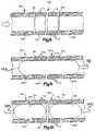
- FIG. 8is a schematic illustration depicting the manner in which a support structure on which viable cells are disposed is utilized to replace a portion of a blood vessel;
- FIG. 9is a schematic illustration depicting the manner in which a balloon is utilized to align the support structure and portions of a blood vessel;
- FIG. 10is a schematic illustration, generally similar to FIG. 9 , illustrating the manner in which a plurality of balloons may be utilized to align the support structure and portions of a blood vessel;
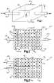
- FIG. 11is a top view of an embodiment of a support structure in the form of a three dimensional mesh of fibers.
- FIGS. 1 and 2An implant 20 is illustrated schematically in FIGS. 1 and 2 .
- the implant 20includes a support structure or matrix 22 ( FIG. 2 ) which may have any desired configuration.
- a plurality of viable cells 24( FIG. 2 ) are positioned on the support structure 22 .
- the support structure 22has been illustrated schematically in FIGS. 1 and 2 as having a rectangular configuration and the viable cells 24 have been illustrated schematically as being disposed in a rectangular array on a rectangular matrix, it is contemplated that the support structure 22 could have any desired configuration and that the viable cells 24 could be disposed in any desired arrangement on the support structure.
- one or more blood vessels 28are connected with the support structure 22 to provide for a flow of blood through the support structure.
- the support structure 22may be connected with blood vessels 28 in many different ways, in the specific arrangement illustrated in FIGS. 1 and 2 , an arteriole (a small artery) 32 and a venule (small vein) 34 are connected with the support structure 22 . This results in a flow of blood from left to right, as indicated by arrows in FIGS. 1 and 2 , through the implant 20 . The viable cells 24 are exposed to the flow of blood.
- the implant 20has been illustrated in FIGS. 1 and 2 as being connected with an artery 32 and vein 34 , it is contemplated that the implant 20 could be connected with one or more arteries or one or more veins. Thus, a portion of the same artery or vein may be connected with opposite sides of the implant 20 . Alternatively, a portion of one artery or vein may be connected with one side of the implant 20 and a portion of another artery or vein may be connected with the opposite side of the implant.
- a plurality of portions of arteries and/or veinsmay be connected with one side of the implant 20 .
- a plurality of portions of arteries and/or veinsmay be connected with the opposite side of the implant 20 .
- the number of portions of arteries and/or veins connected with the implant 20will vary depending upon the location where implant 20 is to be positioned in a patient's body. The patient is a living human.
- the interior of the support structure 20has a plurality of passages through which blood may flow. It is contemplated that capillaries, arterioles, and/or venules may grow in the support structure 20 .
- the outer sides of the support structure 20may be formed of a material which is impervious to blood or a material which restricts the flow of blood from the implant 20 to surrounding tissue.
- the implant 20may be positioned at any desired location in a patient's body.
- the support structure 22may be positioned in an organ, that is, a functional unit of cells.
- the organ in which the support structure 22 is positionedmay be a heart, blood vessel, brain, intestine, stomach, adrenal gland, liver, pancreas, skeleton, spinal cord, or other organ.
- the support structure 22may be positioned in either soft tissue or hard tissue.
- the support structure 22may have a configuration corresponding to the configuration of an entire organ or a portion of an organ. If the support structure 22 has a configuration corresponding to the configuration of a portion of an organ, a plurality of the support structures 22 may be positioned in an organ. The support structures 22 may be positioned adjacent to each other and/or spaced apart from each other in the organ. Although it may be desired to position the support structure 22 in an organ, the support structure may be positioned at other locations in a patient's body.
- the support structure 22may be positioned in a patient's body by fiber optic surgery, such as arthroscopic or laproscopic surgery. It is contemplated that an imaging apparatus and/or a robotic mechanism may be used in positioning the support structure. This may include moving the support structure through a cannula in the manner disclosed in U.S. patent application Ser. No. 10/102,413 filed Mar. 20, 2002 by Peter M. Bonutti and entitled Methods of Securing Body Tissue.
- the implant 20may be connected with tissue in a patient's body in any one of the ways disclosed in the aforementioned application Ser. No. 10/102,413, which is incorporated herein.
- the support structure 22may be formed in many different ways and of many different materials.
- the specific manner in which the support structure 22 is formedwill be influenced, to some extent at least, by the location at which the support structure is to be positioned in the patient's body.
- the manner in which the support structure is formedwill depend upon the overall size of the support structure and whether or not it is to be formed of biodegradable or nonbiodegradable material.
- the support structure 22may be integrally formed as one piece and have a porous construction with openings in which viable cells 24 are positioned.
- the support structuremay be formed by intertwining one or more strands (filaments) of a desired material. The viable cells 24 will be positioned in openings disposed between the intertwined strands.
- the support structure 22may be formed of a hydrophilic material which absorbs body fluid when the support structure 22 is positioned in a patient's body. When the support structure absorbs body fluid, it expands and presses against adjacent body tissues to promote the formation of a mechanical interlock between the support structure 22 and adjacent body tissues. As the hydrophilic material of the support structure absorbs liquid from the patient's body, the volume of the support structure 22 increases. The resulting expansion of the support structure 22 presses the support structure against adjacent body tissue. As this occurs, the material of the support structure 22 and the adjacent tissue are pressed firmly against each other to form a connection between the support structure and the adjacent tissues.
- the formation of a mechanical interlockmay also be promoted by compressing the support structure 22 before insertion of the support structure into the patient's body. When this is done, the support structure forms a mechanical interlock with tissue due to the combined effects of absorbing fluid and resiliently expanding.
- the support structure 22may be formed of a polymeric material which absorbs body liquid.
- the polymeric materialmay be either a copolymer or a dipolymer.
- the polymeric materialmay be natural or synthetic collagen. If desired, the polymeric material may be cellulose, petroylglutamic acid, high purity carboxymethylcellulose, or polylactide.
- the support structure 22may be formed of other know material which absorbs body liquid.
- the support structure 22may be formed of materials disclosed in U.S. Pat. No. 6,152,949 and form an interlock with adjacent body tissues in the manner disclosed in that patent.
- the implant 20may be formed as an entire organ or as a portion of an organ.
- the support structure 22may be formed by removing an entire organ or a portion of an organ from a body.
- the body from which the organ is removedmay be either the patient's body or another body.
- the support structure 22may include a collagen matrix formed by tissue of the organ or portion of an organ removed from a body.
- the organ or portion of an organmay be used as a pattern in the formation of a synthetic support structure.
- the synthetic support structure 22may be either biodegradable or nonbiodegradable.
- the synthetic support structure 22may be molded or woven to have a configuration corresponding to the configuration of the organ or portion of an organ. It is contemplated that the synthetic support structure 22 may have a composite construction and be formed of different materials which have different characteristics.
- the viable cells 24may be any desired type of viable cells. It is contemplated that the viable cells 24 may correspond to cells which were in a damaged organ or other portion of a patient's body. More than one type of viable cell 24 may be positioned on the same support structure 22 . The support structure 22 and viable cells 24 may be positioned in either hard or soft tissue.
- the viable cells 24 on the support structure 22will have characteristics associated with the characteristics of normal cells in the organ in which the support structure is to be positioned. Many organs contain cells which have different characteristics and perform different functions within the organ. It is contemplated that the viable cells 24 on the support structure 22 may have different characteristics corresponding to the different characteristics of cells of an organ. When the support structure 22 is to be positioned outside of an organ, the cells positioned on the support structure may have any desired characteristic or combination of characteristics.
- the viable cellscan be pluripotent cells that are directed to differentiate into the desired cell type or types.
- One example of such cellsis stem cells.
- the differentiationcan be controlled by applying or exposing the cells to certain environmental conditions such as mechanical forces (static or dynamic), chemical stimuli (e.g. pH), and/or electromagnetic stimuli.
- More than one type of cellmay be positioned on the support structure 22 .
- the type of cell positioned at a particular location on the support structure 22will be determined by the orientation of the support structure in a patient's body and by the specific type of tissue desired at a particular location in a patient's body.
- stromal cellsmay be positioned at a location where foundation tissue is desired and another type of cell may be positioned at locations where it is desired to have tissue perform a special function.
- the present inventionenvisions harvesting and culturing cells prior to placement within the support structure 22 . Although most researchers tend to isolate and grow one basic cell line, it may be beneficial to mix multiple different cell lines together. For example, embryonic cells or fetal cells can be used to grow cartilage or any desired tissue (such as liver or pancreas) and these can be combined with the mature cells of an older individual. The older individual can either be the patient receiving the mixed cells or possibly another healthier individual. Regardless of the source, the net result is a combination of two cell populations, one younger and more vibrant and another which is older, more mature. The younger cells may have more of an ability to differentiate into the desired cell type, while the older cells may have more of the regulatory factors, tissue inductive factors, etc, which would be more likely to guide and control the younger cells.
- Growth factors or other therapeutic agentscan be added to either or both of the cell types.
- the addition of the agentscan be before and/or after combining the cells.
- growth factorsinclude insulin-like growth factor (IGF-1), fibroblast growth factor (FGF), transforming growth factor (TGF- ⁇ ), hepatocyte growth factor (HGF), platelet-derived growth factor (PDGF), Indian Hedgehog (Inh) and parathyroid hormone-related peptide (PTHrP), bone morphogenetic proteins (BMPs), and Interleukin-1 receptor antagonist (IL-1ra).
- IGF-1insulin-like growth factor
- FGFfibroblast growth factor
- TGF- ⁇transforming growth factor
- HGFhepatocyte growth factor
- PDGFplatelet-derived growth factor
- IhIndian Hedgehog
- PTHrPparathyroid hormone-related peptide
- BMPsbone morphogenetic proteins
- IL-1raInterleukin-1 receptor antagonist
- cellswhich may be positioned on the support structure 22 . These cells include progenitor cells which differentiate and proliferate to form cells having desired characteristics; stromal cells which relate to foundation supporting tissue; and mesenchymal cells which relate to connective tissues, blood and blood vessels, and other systems. Fibroblasts may be used in the production of connective tissues. Osteoblasts may be used in the production of hard tissue (bone). Myoblasts may be used in the production of muscle.
- Specific cellsmay be used to provide for growth of tissue having a function associated with the cell. These cells may include reticular cells, smooth muscle cells, chondrocytes, retinal cells, endothelial cells, and other known cells.
- the cellscan include endocardial, myocardial, and pericardial cells. These cells can be layered or otherwise arranged. If cartilage and bone tissue is desired, a combination of chondrocytes (and/or chondroblasts) and osteoblasts, or their precursors can be used.
- bone marrowwhich contain progenitor cells. These progenitor or stem cells can be treated so as to differentiate into any desired cell type.
- Fetal cellscan be harvested directly from the fetus in situ using minimally invasive techniques or through procedures such as amniocentesis, chorionic villus sampling (CVS), and other similar methods that do not involve invasive contact with the fetus.
- image guidanceMRI guidance, ultrasonic guidance, etc
- Computer assisted techniquescan be used in conjunction with the image guidance.
- the harvestingcan be performed using a robotic or haptic system.
- fetal cellssuch as liver, pancreas, or renal cells, etc
- specific types of fetal cellssuch as liver, pancreas, or renal cells, etc, could be selectively harvested.
- the fetusdoes not necessarily have to be harmed during the harvesting, but can be kept viable. Thus, the fetus does not have to be aborted after obtaining the cells, but actually could be left alive and could be a source for cells possibly through one or multiple aspirations while the fetus is still growing. For example, one may require multiple aspirations of liver cells or neural cells, with multiple cell types at various levels of maturation for the desired graft.
- the implant 20includes the support structure 22 on which the viable cells 24 are disposed.
- the viable cells 24are exposed to a flow of blood between the blood vessels 32 and 34 .
- the blood vessels 32 and 34are connected with the support structure 22 .
- the bloodflows through the blood vessels 32 and 34 in the manner indicated by arrows in FIGS. 1 and 2 .
- the blood vessels 32 and 34may be connected with a support structure 22 in any desired manner.
- an end portion of the arteriole 32is stitched to the support structure 22 .
- an end portion of the venule 34is stitched to the support structure 22 .
- the implant 20may be retained in tissue in a patient's body by stitching the support structure 22 to the tissue in the patient's body.
- the blood vessels 28may be connected with the support structure in many different ways.
- the arteriole 32may be connected with the support structure 22 by an adhesive such as cyanoacrylate (so-called “superglue”), Polylatic acid, or fibrin.
- the modified biofilm discussed below in connection with the attachment of cells to the support structure 22can be used to couple the arteriole 32 and the support structure 22 .
- the end portion of the venule 34may be connected with the support structure 22 by an adhesive in the same manner as in which the arteriole 32 is connected with the support structure. It should be understood that the blood vessels 32 and 34 could both be arterioles or venules if desired.
- appropriately shaped and sized recessesmay be provided in the support structure 22 . These recesses would have an inside dimension which is only slightly larger than the outside diameter of the arteriole 32 and/or venule 34 .
- the arteriole 32for example, would be telescopically inserted into the cylindrical recess in the support structure 22 .
- the joint between the support structure and the exterior surface of the arteriole 32may be sealed with a suitable sealant. It is contemplated that an adhesive could be utilized as the sealant.
- the arteriole 32 and venule 34are shown as being axially aligned with each other, that is, they are in a coaxial relationship.
- the arteriole 32could be offset to one side, for example, to the left, and the venule 34 offset to the opposite side, for example, to the right, of the central axis of the support structure 32 .
- Thiswould promote a dispersion of the flow of blood from the arteriole in the support structure 22 before the flow of blood entered the venule 34 .
- thiswould increase the exposure of the viable cells 24 to the flow of blood.
- the arteriole 32could be inserted for a substantial distance, into the support structure 22 and the venule 34 inserted for a substantial distance into the support structure 22 . If this was done, it is contemplated that the arteriole 32 would be offset from the venule 34 . Thus, the arteriole 32 could be offset downward (as viewed in FIG. 2 ) and the venule 34 offset upward (as viewed in FIG. 2 ) so that they are not in axial alignment with each other.
- the flow of bloodwould exit the arteriole adjacent to the side of the support structure from which the venule 34 extends, that is, the right side of the support structure 22 (as viewed in FIG. 2 ).
- the venule 34would extend telescopically into a recess which extends past the center of the support structure 22 . This would result in the flow of blood in the support structure 22 entering the venule 34 adjacent to the left (as viewed in FIG. 2 ) side of the support structure 22 .
- the arteriole 32 and venule 34would not be axially aligned with each other but would be offset so that the blood would flow from the arteriole 32 in a reverse direction, that is toward the left as viewed in FIG. 2 , to the entrance to the venule 34 .
- the bloodwould flow from the end of the arteriole 32 adjacent to the right (as viewed in FIG. 2 ) side of the support structure 22 to the end of the venule 34 adjacent to the left (as viewed in FIG. 2 ) side of the support structure.
- the resulting nonlinear flow of blood between the arteriole 32 and venule 34would promote dispersion of the blood in the support structure 22 and promote exposure of the viable cells 24 to the flow of blood.
- the arteriole 32 and venule 34are connected directly to the support structure 22 .
- the support structure 22could be provided with a pair of conduits which are connected between an artery and vein in a patient's body.
- the support structure 22may be provided with a tubular conduit in place of the arteriole 32 of FIGS. 1 and 2 and a tubular conduit in place of the venule 34 .
- the tubular conduit which replaces the arteriole 32would be connected with an artery in the patient's body and the tubular conduit which replaces the venule 34 would be connected with a vein in the patient's body.
- the tubular conduits which extend from the support structure 22may be formed of a synthetic material or may be formed by veins and/or arteries harvested from the patient's body or from another body.
- a plurality of support structures 22may be implanted into a patient's body. If this is done, the plurality of support structures 22 may be interconnected by conduits before being placed in the patient's body. The plurality of the support structures 22 may be interconnected to have parallel and/or series flow of blood through the support structures 22 .
- feeder conduitscould extend from a manifold conduit to conduct a flow of blood to each support structure 22 of a plurality of support structures. If this is done, a second plurality of feeder conduits may extend from a second manifold conduit to each of the support structures to conduct a flow of blood from the plurality of support structures.
- the first manifold conduitmay be connected in fluid communication with an artery in a patient's body and the second manifold conduit may be connected with a vein in a patient's body. This would enable a plurality of support structures 22 to be supplied with blood conducted from a single connection between the first manifold conduit and an artery. Similarly, blood would flow from the plurality of support structures 22 to a vein through a single connection between a vein and the second manifold conduit. If desired, the first and second manifold conduits could both be connected with either an artery or a vein.
- interconnecting a plurality of support structures 22 with suitable conduits before the support structures are positioned in a patient's bodywill facilitate positioning of the support structures. This is because the number of connections which have to be made between the support structures 22 and the blood vessels in the patient's body would be minimized.
- a plurality of support structureWhen a plurality of support structure are utilized they may be interconnected in a parallel blood flow arrangement in the manner previously described or in a series blood flow arrangement before being positioned in the patient's body.
- the sides of the support structure 22may be constructed as to retard a flow of blood from the support structure.
- the support structure 22may be constructed with outer side surfaces that effectively block a flow of blood from the support structure through the outer side surfaces of the support structure.
- the outer sides of the support structure 22may be provided with very small openings which effectively retard, without completely blocking, a flow of blood through the sides of the support structure.
- the sides of the support material 22are made of a material that has one-way permeability. This would either allow absorption of blood while preventing discharge, or allow blood discharge while preventing absorption.
- the side walls 40are effective to block the flow of blood from the support structure 22 , all of the blood which enters the support structure 22 from the arteriole 32 ( FIGS. 1 and 2 ) would flow from the support structure through the venule 34 . However, if the side walls 40 are somewhat porous so that they are effective to retard or only partially block a flow of blood through the side walls 40 , a portion of the blood from the arteriole 32 would flow from the support structure 22 through the side walls 40 of the support structure while the remainder of the blood from the arteriole 32 would flow from the support structure through the venule 34 . By allowing some, but not all, of the blood to flow from the support structure 22 through the side walls 40 , dispersion of blood within the support structure is promoted.
- minute passagesmay be provided in the support structure 22 to accommodate the growth of capillaries within the support structure.
- a network or web of capillariesmay grow in the support structure 22 between the arteriole 32 and venule 34 .
- This network of capillarieswould facilitate supplying blood to all of the viable cells 24 within the support structure 22 .
- the side walls 40 ( FIG. 1 ) of the support structure 22may have small openings through which capillaries grow between the support structure and surrounding tissue in the patient's body.
- a single arteriole 32is connected with a support structure 22 to conduct blood to the support structure and a single venule 34 is connected with the support structure to conduct blood from the support structure. It is contemplated that a plurality of arterioles 32 and/or venules 34 may be connected with the support structure 22 . Thus, a plurality of arterioles 32 may be connected with a first side wall 40 of the support structure 22 to conduct a flow of blood into the support structure at a plurality of locations. Similarly, a plurality of venules 34 may be connected with a second side wall 40 of the support structure 22 at a plurality of locations to conduct blood from the support structure. The number of arterioles 32 connected with the support structure 22 may be the same as, greater than, or less than the number of venules 34 connected with the support structure.
- a plurality of conduitsmay be connected with one of the side walls 40 of the support structure 22 . These conduits may all be connected with a single relatively large conduit. This relatively large conduit would be connected with an artery in a patient's body in an operating room. Similarly, a plurality of conduits may be connected with a second side wall of the support structure 22 and be connected with a second single conduit. This single conduit may be connected with a vein in a patient's body in an operating room. This would minimize the number of connections which would have to be made with the support structure 22 during a surgical procedure in an operating room and would enable most of the connections to be made in a less stressful environment remote from the operating room.
- Tissue inductive growth factors and/or other therapeutic agentsmay be provided on the support structure 22 to promote a growth of tissue between the patient's body and the support structure 22 .
- the tissue growth inductive factorsmay promote a growth of blood vessels, such as capillaries, between tissue and the patient's body and the support structure 22 .
- the tissue inductive growth factorsmay also promote the growth of connective tissue between the support structure 22 and the tissue in the patient's body to securely connect the support structure in place in the patient's body.
- additivesinclude materials such as plasticizers, citrate esters, hexametholsebacate, antibiotics (e.g., tetracyclines, penicillins, mefronidazole, clindamycin, etc.), to prevent infection, etc., or to accomplish other desired conditions or results.
- Additional additives or therapeutic agentsinclude osteoinductive, biocidal, or anti-infection substances. Suitable osteoinductive substances include, for example, growth factors.
- the growth factorsmay be selected from the group of IGF (insulin-like growth factors), TGF (transforming growth factors), FGB (fibroblast growth factors), EGF (epidermal growth factors), BMP (bone morphogenic proteins), and PDGF (platelet-derived growth factors).
- the therapeutic agent(s)may be contained within the material of the support structure 22 .
- the agent(s)may be disposed in a structure which is separate from the support structure 22 .
- tissue inductive growth factorscould be disposed in a collagen sponge which is positioned adjacent to the support structure 22 in the patient's body.
- the agent(s)may be positioned in a structure which is connected to the support structure 22 .
- agent(s)adjacent to the patient's body tissue and the viable cells 24 .
- the agent(s)could be held in a biodegradable container or containers which degrade over a period of time and slowly release the agent(s).
- the support structure 22can be pretreated with an agent that promotes cell adhesion.
- an agent that promotes cell adhesionis an organic substance based on a biofilm.
- a biofilmis a slimy, glue-like substance that forms when bacteria attach to surfaces exposed to water. Typically, colonies of biofilm bacteria are unwanted as they carry out a variety of detrimental reactions.
- a sterile biofilmmay be used to promote initial attachment of cells to the support structure 22 .
- the sterile biofilmcould be engineered to isolate the glue-like substance while eliminating the adverse properties of the bacteria.
- the resulting sterile glue-like substancewould be used to help the cells stick to the support structure 22 .
- the engineered biofilmcould be added to the support structure 22 in the laboratory that produces the support structure or just prior to the addition of the cells by the user. Alternatively, the biofilm and support structure could be combined intra-corporally.
- This biofilmalso could be used as an independent polysaccharide based adhesive with mild to moderate adhesion forces.
- the biofilmcould serve as a surgical adhesion or grouting for cells, for tissue fixation (soft tissue to soft tissue, soft tissue to bone, etc.) and as a sealant.
- the biofilmcould be used in conjunction with other implants and devices.
- the biofilmcould be used to coat a stent.
- the coatingcould serve as a top coat covering a layer of a therapeutic agent or be impregnated with the therapeutic agent.
- the agentis delivered locally in a time-released fashion.
- the support structure 22may be formed of a biodegradable material.
- the biodegradable materialwould at least partially degrade after the patient's body tissue has grown into the support structure 22 .
- the support structure 22may be formed of a plurality of materials. Some of these materials may be biodegradable and some of the materials may not be biodegradable. But by forming the support structure 22 as a composite of both biodegradable and nonbiodegradable materials, a portion of the support structure would degrade with passage of time while another portion of the support structure would remain.
- the support structure 22When the support structure 22 is formed entirely of biodegradable materials, it is contemplated that portions of the structure may degrade before other portions. Thus, one portion of the support structure 22 may be formed of material which degrades over a relatively long period of time while other portions of the support structure 22 may be formed of materials which degrade over a shorter period of time.
- tissue inductive growth factors on the support structurewould promote the growth of tissue into the support structure during the degradation of material of the support structure.
- the support structure 22may be relatively large and provide for growth of a substantial volume of tissue in a patient's body. Alternatively, the support structure 22 may be relatively small. If a relatively small support structure 22 is utilized, it is believed that a plurality of the support structures may be positioned in a patient's body. The individual support structures of the plurality of support structures may be positioned adjacent to each other or spaced apart from each other.
- the implant 20When the implant 20 is to be positioned relative to the body tissue, the implant may be moved through a cannula, such as the expandable cannula disclosed in U.S. Pat. No. 6,338,730, into the body tissue.
- An opening for the support structure 22may be formed in the body tissue utilizing minimally invasive surgical techniques similar to those disclosed in U.S. Pat. No. 6,174,313.
- the surgical techniquesmay involve moving one or more devices through an expandable cannula into the body tissue.
- the devices moved into the patient's bodymay be guided by using magnetic resonance imaging systems, ultrasonic imaging apparatus, fluoroscopic apparatus and/or other imaging techniques.
- the fluoroscopic apparatusmay have a construction similar to that disclosed in U.S. Pat. Nos.
- a plurality of endoscopesmay be utilized to generate stereoscopic images, that is, three dimensional images, of an area where the implant 20 is to be positioned.
- the endoscopes and other imaging devicesmay be utilized in a manner which is the same as is disclosed in U.S. patent application Ser. No. 10/102,413 filed Mar. 20, 2002 by Peter M. Bonutti and entitled Method of Securing Body Tissue.
- the drapery systemmay include a drape which is either integrally formed as one piece with a surgeon's gown or is formed separately from the surgeon's gown and is connected with the surgeon's gown.
- the drapery systemmaintains a sterile field which extends from the surgeon to space adjacent to the patient. This enables the surgeon to move relative to the patient without contaminating the sterile field.
- the drapery systemmay be constructed in the manner disclosed in U.S. patent application Ser. No. 10/263,893 filed Oct. 3, 2002 by Peter M. Bonutti and entitled Surgical Draping System.
- a plurality of relatively small support structures 22are to be positioned in a patient's body, it is believed that it may be desired to interconnect the plurality of support structures with a network of conduits prior to insertion of the support structures into the patient's body.
- a relatively large number of support structures 22may be interconnected by a web of conduits.
- the resulting mesh or network formed of the plurality of small support structures 22 and conduitsmay be loosely positioned over soft tissue in a patient's body.
- Each of the support structures 22may then be individually implanted or moved into soft body tissue.
- the webbing of conduitswould extend between the individual support structures 22 .
- the webbing of conduitswould then be connected with the patient's vascular system.
- the number of connections to the patient's vascular system for a relatively large number of support structureswould be minimized.
- the webbing or network of support structures 22would be anchored in the patient's body tissue at each location where a support structure was implanted.
- the webbing of conduitswould be effective to conduct a flow of blood to and from the various support structures 22 in the network.
- the viable cells 24 in the plurality of support structures 22 interconnected by the network of blood conduitsmay be the same type of cells or different types of cells. It is believed that it may be particularly advantageous to have different types of cells in at least some of the support structures 22 .
- one of the support structures 22may contain viable endocrine cells and another support structure may contain viable stromal cells. Still another support structure may contain viable endothelial cells.
- viable endocrine cellsmay all be provided in one support structure 22 of the plurality of support structures interconnected by a network of conduits which conduct blood to the support structures.
- viable stromal cellsmay all be provided in one support structure 22 of the plurality of support structures interconnected by a network of conduits which conduct blood to the support structures.
- the support structure 22may be configured so as to provide for the positioning of a layer of viable cells 28 in a patient's body.
- the viable cellsmay be allograft mesenchymal cells and/or stem cells.
- the flow of bloodis conducted from the arteriole 32 to the support structure 22 and from the support structure to the venule 34 .
- the support structure 22contains a matrix of viable cells 24 ( FIG. 2 ).
- blood flow within the support structure 22is controlled to maximize the exposure of the viable cells 24 to the flow of blood.
- an implant 20includes a support structure 22 .
- Blood vessels 28are connected with the support structure 22 .
- the blood vessels 28include an arteriole 32 and a venule 34 .
- the arteriole 32 and venule 34are connected to the same side wall 40 of the implant 20 .
- a barrier 48FIG. 3 is provided in the support structure 22 .
- the barrier 48is effective to direct the flow of blood in the support structure 22 .
- the barrier 48may extend between and be connected with opposite side walls 40 of the support structure 22 . Alternatively, the barrier 48 may be spaced from the side walls of the support structure.
- the barrier 48may be formed of either a material which is impervious to a flow of blood or a material having small openings through which blood can flow. If the barrier 48 is provided with small openings through which blood can flow, the openings would be small enough to retard a flow of blood through the barrier. It is contemplated that barrier 48 may be integrally formed as one piece with a support structure 22 or formed separately from the support structure and mounted in the support structure.
- the flow of blood from the arteriole 32cannot readily move upward (as viewed in FIG. 3 ) through the barrier 48 . Therefore, the blood will flow downward towards the viable cells 24 in the lower portion of the support structure 22 . The blood from the arteriole 32 will subsequently flow upward from the lower portion of the support structure toward the upper portion of the support structure. When the blood is has moved around the right (as viewed in FIG. 3 ) end of the barrier 48 , the blood can flow upward through the upper portion of the support structure 22 .
- the upper portion of the support structure 22is connected with the venule 34 which conducts the flow of blood from the support structure 22 to a vein.
- the barrier 48 , arteriole 32 and venule 34 illustrated in FIG. 3it is believed that it would be desired to form the lower side wall 40 of the support structure 22 of a material which blocks or at least substantially blocks a flow of blood. It may also be desired to have the upright (as viewed in FIG. 3 ) side walls 40 of the retainer of support structure 22 formed of a material which blocks or at least partially blocks a flow of blood. This construction would tend to promote the flow of blood from the lower portion of the support structure 22 to the upper portion of the support structure.
- the barrier 48may be constructed of a plurality of members which are either interconnected or spaced apart to cause the blood to flow along a convoluted path between the arteriole 32 and venule 34 of FIG. 3 .
- the barrier 48may be constructed with a plurality of bends which cause the blood to flow from the arteriole 32 through a maze in the support structure 22 to promote the flow of blood past each of the viable cells 24 .
- itmay be desired to form the barrier 48 of a material through which the blood can flow between various turns and passages in the maze formed within the support structure 22 . With a passage of time, it is believed that capillaries may tend to grow in micron size passages in the support structure 22 .
- the support structure 22has been illustrated as having a polygonal configuration, specifically a rectangular configuration. However, it is contemplated the support structure 22 could have a different configuration if desired. For example, rather than the cubicle configuration illustrated in FIGS. 1-3 , the support structure could have a configuration of a polyhedron with generally flat sides. Alternatively, the support structure 22 could have a spherical, oval, or ovoid configuration.
- the specific configuration of the support structure 22is a function, in part at least, of a location where the support structure is to be positioned in a patient's body.
- the configuration of the side walls 40 of the support structure 22will have an influence on the configuration on the barrier 48 . It should be understood that the barrier 48 may have an arcuate configuration and may be formed as a portion of a sphere or cylinder.
- FIGS. 1-3the same number of conduits are utilized to conduct blood to the implant as are used to conduct blood from the implant.
- a single arteriole 32 and a single venule 34are connected with a support structure 22 which has a relatively simple cubicle construction.
- a simple one piece barrier 48has been illustrated in FIG. 3 to direct a flow of blood within the support structure 22 .
- the number of conduits utilized to conduct blood to the implantis different than the number of conduits utilized to conduct blood from the implant.
- the implant 20has a complex configuration formed by flat and arcuate surfaces. A multi-piece barrier is provided in the implant to direct the flow of blood.
- a single arteriole 32conducts a flow of blood to the support structure 22 .
- a plurality of venules 34conduct the flow of blood from the support structure 22 .
- a greater number of venulesmay be provided if desired.
- a greater number of arterioles 32could also be connected with the support structure 22 if desired.
- the number of arterioles 32may exceed the number of venules 34 if desired.
- a plurality of viable cells 24are provided within the support structure 22 .
- a barrier 48is provided within the support structure 22 .
- the barrier 48is formed of a plurality of pieces or sections.
- One section 56 of the barrier 48has a generally conical configuration.
- the section 56 of the barrier 48has an open left (as viewed in FIG. 4 ) end portion to enable blood from the arteriole 32 to flow through the leftward end portion of the generally conical section 56 of the barrier.
- the barrier 48includes a flow splitter 58 which disperses a flow of blood entering the open left (as viewed in FIG. 4 ) end of the conical section 56 of the barrier.
- the flow splitter section 58 of the barriermay be formed by a plurality of pieces or by a single piece.
- the flow splitter section 58may be aligned with the opening in the left end of the barrier 48 or may be offset relative to the opening.
- the splitter section 58could be formed by a plurality of spaced apart sections each of which is offset slightly from the central axis of the opening formed in the left (as viewed in FIG. 4 ) end portion of the section 56 of the barrier 48 .
- arteriole 32 and venules 34may be connected with the support structure 22 of FIG. 4 in any one of the manners previously discussed herein. Rather than connecting an arteriole 32 and venules 34 with the implant 20 as it is positioned in the patient's body, conduits may extend from the support structure 22 and be connected with one or more arteries and/or one or more veins in the patient's body. It should be understood that either a greater or lesser number of arterioles 32 and/or venules 34 may be connected with the support structure 22 . The arterioles 32 and venules 34 may be connected with the support structure in any one of the manners previously mentioned herein.
- the implant 20 of FIGS. 1-4may be positioned in either soft or hard tissue in a patient's body. It is believed that it may be desired to position one or more of the implants 20 in an organ in a patient's body. If this is done, the implant may be provided with one or more side walls 40 having a configuration which corresponds to a configuration of the exterior surface of the organ.
- the implants 20 of FIGS. 1-4could be utilized in association of any one of the many different organs in a patient's body, the implants are described in conjunction with a kidney 66 ( FIG. 5 ) disposed in the patient's body. It should be understood that the kidney 66 is only an example of one specific organ, that is, a functional unit of cells, with which the implants of FIGS. 1-4 may be associated.
- the kidney 66has a renal artery 68 through which blood is conducted to the kidney.
- the kidney 66has a renal vein 70 through which blood is conducted from the kidney.
- a ureter 72conducts urine from the kidney 66 to the patient's bladder.
- the renal artery 68 , renal vein 70 and ureter 72are connected with a renal capsule 74 .
- a kidney 66When a kidney 66 becomes damaged by trauma and/or disease, it may be desired to rejuvenate the kidney through the use of one or more implants corresponding to the implants 20 of FIGS. 1-4 .
- the implants 20may be positioned in a spaced apart relationship in the kidney 66 or positioned adjacent to each other. The specific location and arrangement of the implants 20 in the kidney 66 will depend upon the extent and type of damage which the kidney has incurred.
- the size and number of the implants positioned in the kidney 66 , as well as their location in the kidneycan be varied in the manner believed to be the best remedy for damage to the kidney.
- a plurality of the implants 20may be positioned at spaced apart locations in the kidney 66 ( FIG. 6 ).
- the plurality of the implants 20may be positioned in engagement with each other at selected locations in the kidney 66 . Since the implants 20 are relatively small, the locations where they are positioned in the kidney 66 can be selected to best compensate for the damage incurred by the kidney.
- the implantWhen a single implant 20 is to be positioned in the kidney, the implant may be connected with blood vessels in the kidney in the manner previously described in conjunction with FIGS. 1-4 herein. Alternatively, a plurality of the implants 20 may be connected in series with each other so that blood flows from one implant to the next succeeding implant. As was previously mentioned herein, the implants 20 may be connected in parallel with each other and with an artery which supplies blood to the implants and a vein which receives the blood from the implants. As was also previously mentioned, the implants 20 may be associated with any desired organ in the patient's body. The kidney 66 of FIGS. 5 and 6 is only representative of many organs in a patient's body.
- a recess or opening having a configuration corresponding to the configuration of the implantis cut into the kidney.
- the implant 20is then connected with blood vessels in the kidney 66 and is positioned in the opening ( FIG. 6 ).
- the openingmay be sized so as to accept a single implant 20 or a plurality of implants. If the opening is sized to accept a single implant 20 , the size of the single implant may be either relatively small or relatively large depending upon the damage which has been occurred by the kidney.
- a sectionthat is a relatively large piece of a kidney.
- a single implant 20 having a configuration corresponding to the configuration of the removed section of the kidneymay be implanted at the location where the section was removed from the kidney. Since the relatively large implant 20 has the same configuration as the exterior surface of the kidney, when tissue grows into the implant, the implant will form a portion of the kidney having the same configuration as the section which was removed from the kidney.
- the viable cells 24may include renal cells having characteristics of replaced cells in the kidney. Some of the viable cells in the implants 20 may be stromal cells and/or fibroblast. Depending upon the location where the implants 20 are positioned in the kidney, some of the viable cells 24 may be endothelial cells. Thus, stromal cells, renal cells, and endothelial cells may be positioned on a single implant 20 which is connected with the kidney 66 . Of course, other types of cells may be positioned on the implant if desired.
- the implants 20have been illustrated in FIG. 6 as being positioned in the kidney 66 , it is contemplated that the implants 20 may be positioned in a different organ if desired.
- the implants 20may be positioned in a patient's heart or one or more of the bones of the patient's skeleton. It is contemplated that the implants 20 may be used for applications other than partial or total organ replacement.
- the implant 20may be located at any desired location in either hard or soft tissue in the patient's body.
- a support structure 22 having a configuration corresponding to the configuration the organ to be replacedis formed.
- This support structure 22may be naturally formed or synthetically formed.
- the organ to be replacedmay be any one of the organs in the patient's body.
- kidney 66is the organ in a patient's body to be replaced, it may be desired to form a support structure having a configuration corresponding to the configuration of the kidney 66 .
- a kidney 66is obtained from a body.
- the kidney 66may be obtained from a patient's own body, from the body of another living human, from a cadaver (dead human body), or from a living or dead animal.
- any living cells on a kidney 66 removed from a living donormay be killed with a cytotoxic solution, such as a strong saline solution.
- the living cellsmay be killed by radiation.
- other methodscould be utilized to kill the living cells.
- the renal artery 68 , renal vein 70 and ureter 72are severed and the kidney 66 is removed from the cadaver.
- Dead cells and/or other tissueare removed from the cadaver kidney to leave a collagen matrix having a configuration corresponding to the configuration of the kidney in the cadaver.
- the collagen matrixmay have a relatively large portion with a configuration corresponding to the configuration of the renal capsule 74 ( FIG. 5 ), and three tubular conduits corresponding to the renal artery 68 , renal vein 70 and ureter 72 .
- the collagen matrixis utilized as a support structure 22 for viable cells, corresponding to the viable cells 24 of FIGS. 1-4 . It is contemplated that the viable cells 24 will be different types of cells and will be placed at various locations in the collagen matrix forming the support structure 22 made from the cadaver kidney.
- renal cellsmay be positioned in the portion of the collagen matrix formed by the cadaver kidney corresponding to the renal capsule 74 .
- Endothelial cellsmay also be positioned on the portion of the collagen matrix corresponding to the renal capsule 74 and on the portions of the collagen matrix corresponding to the renal artery 68 , renal vein 70 and ureter 72 .
- stromal cellsmay be positioned on the portion of the collagen matrix corresponding to the renal capsule 74 , renal artery 68 , renal vein 70 and ureter 72 .
- Fibroblast and mesenchymal cellsmay also be placed on the support structure 22 formed from the cadaver kidney.
- materials for promoting growth of tissuemay be positioned on the support structure.
- the replacement kidney 66may be formed at a location spaced from an operating room. After the replacement kidney 66 has been formed, it may be transported to the operating room and implanted in the patient.
- the damaged kidney in the patientis removed. Removal of the damaged kidney 66 from the patient would involve severing the renal artery 68 , renal vein 70 and ureter 72 connected with the damaged kidney in the patient.
- the renal artery 68 of the replacement kidneyis connected with the portion of the renal artery remaining in the patient's body.
- the renal vein 70 of the replacement kidney 66is connected with the portion of the renal vein remaining in the patient's body.
- the ureter 72 on the replacement kidney 66is connected with the portion of the ureter remaining in the patient's body. The replacement kidney 66 is then moved to a desired location in the patient's body.
- Bloodis conducted to the replacement kidney 66 through the remaining portion of the patient's renal artery 70 and the portion of the renal artery associated with the replacement kidney. Blood is conducted from the replacement kidney 66 through the portion of the renal vein 70 associated with the replacement kidney and the remaining portion of the patient's renal vein. Urine is conducted from the replacement kidney 66 through the portion of the ureter 72 associated with the replacement kidney and to the remaining portion of the patient's ureter.
- the method described hereinmay be used in association with the replacement of the other organs in a patient's body.
- the method described hereinmay be used in conjunction with the replacement of an adrenal gland, heart, liver, bone, pancreas, or other organ.
- the cadaver kidneymay be utilized as a pattern to form a mold cavity having a configuration corresponding to the configuration of the cadaver kidney.
- the cadaver kidney 66( FIG. 7 ) may be enclosed with mold material 80 .
- the mold materialmay be divided into two segments 82 and 84 ( FIG. 7 ).
- the pattern 66is enclosed by the mold material 80 and the mold material is solidified around the pattern to form the two segments 82 and 84 .
- the kidney patternis separated from the mold.
- the two segments 82 and 84may be interconnected to form a mold assembly which defines a recess or cavity 88 .
- the recess or cavity 88has a configuration which corresponds to the configuration of the pattern kidney along with the attached portions of the renal artery 68 , renal vein 70 , and ureter 72 .
- the kidney pattern 66may be obtained from a patient, from another living human, from a cadaver, or from an animal. It is believed that it may be preferred not to use the patient's own kidney as the kidney pattern 66 since the configuration of the patient's own kidney-may be unsuitable. If desired, an artificial pattern, having a configuration corresponding to a desired configuration of a kidney may be used as a pattern for the mold cavity 88 .
- a synthetic support structure 22is formed in the mold cavity 88 . This may be accomplished by injecting a material into the recess or cavity 88 while the two mold segments 82 and 84 are interconnected.
- the material injected into the mold cavity 88may be either biodegradable or nonbiodegradable.
- the material injected into the mold cavity 88solidifies with an open cell porous structure. Synthetic collagen or polylatic acid with a chemical blowing agent or entrained gas may be utilized to form the porous support structure.
- the material injected into the mold cavityWhen the material injected into the mold cavity has solidified with an open cell porous structure, it will have a configuration corresponding to the configuration of the renal capsule 74 of the kidney pattern 66 , the renal artery 68 , renal vein 70 and ureter 72 connected with the renal capsule of the kidney pattern.
- the resulting support structure 22is formed as one piece of porous material.
- the selected viable cellsare positioned in small openings or pores of the cast porous support structure 22 having the configuration of a kidney. It is contemplated that the viable cells 24 may be positioned in any one of many different known ways on the porous support structure 22 having the configuration of a kidney.
- One way in which the viable cells may be positioned on the porous support structure 22is to inject a liquid solution containing the viable cells 24 into the porous support structure 22 .
- the viable cells 24would be the deposited in the porous of the support structure 22 as the liquid dries.
- a different solution with different viable cellsmay be injected in different portions of the porous support structure 22 .
- the viable cells 24may be any of the viable cells previously mentioned herein. Of course, the viable cells 24 would be deposited on the porous support structure 22 in accordance with the desired tissue structure to be obtained by growth of the viable cells. Other known methods of positioning viable cells on a support structure may be utilized if desired.
- the support structuremay be formed of intertwined strands or filaments ( FIG. 11 ).
- the strands or filamentsmay be woven together in the recess or cavity 88 formed by the mold segments 82 and 84 . This would result in the intertwined filaments or strands having an overall configuration corresponding to the configuration of the pattern kidney 66 of FIG. 7 .
- the intertwined strands or filamentswould define relatively small spaces in which the viable cells 24 would be positioned.
- the viable cells 24may be positioned on the woven support structure by injecting a solution containing the viable cells into the spaces or recesses formed by the intertwined strands of the support structure.
- different types of viable cells 24would be positioned at different locations in the woven support structure. Any one of the desired types of viable cells 24 previously mentioned herein may be utilized. It should be understood that the specific viable cells 24 positioned at a specific location on the woven support structure 22 would depend upon the desired characteristics of the tissue to be grown at that location.
- the strands of the woven support structure 22may be either a naturally occurring materials or synthetic materials.
- the strands of the woven support structure 22may be biodegradable or nonbiodegradable. It is contemplated that strands of synthetic or natural collagen may be utilized to form the woven support structure 22 on which the viable cells 24 are positioned.
- the exterior of the woven support structure 22may be sealed by encapsulating the woven support structure with a material through which blood cannot easily flow.
- the material used to encapsulate the woven support structuremay be either biodegradable or nonbiodegradable. It is contemplated that a suitable polymeric material, such as polylatic acid, may be utilized. It is believed that blood vessels, such as capillaries, will grow through small passages or channels formed in the woven support structure.
- pancreasmay be replaced.
- relatively small implantscorresponding to the implants 20 of FIGS. 1-4 , may be positioned in the pancreas.
- the specific types of viable cellsthat is islets of Langerhans, endocrine, and/or exocrine cells would be positioned at the location on the support structure 20 where the corresponding tissues are to be grown.
- a portion of the patient's hard tissuemay be replaced using the foregoing methods. If this is to be done, a support structure 22 having a configuration corresponding to a configuration of at least a portion of one of the bones in the patient's skeleton would be replaced.
- the viable cells 24 positioned on the support structure 22may be osteoblasts and/or mesodermal cells.
- osteochondral cellsmay be positioned on the support structure 22 .
- Myoblastsmay be utilized in association with the support structure 22 to promote the growth of muscular tissue.
- a portion of an organmay be replaced.
- a segment of a blood vessel 96is to be replaced.
- the method of the present inventionmay be used to replace portions of an organ other than a blood vessel.
- the segment of the blood vessel 96has been selected to be representative of a portion of many different organs in a patient's body.
- the portion of the patient's blood vessel between the cuts 98 and 100is removed.
- An implant 104is positioned between the cuts and connected with segments 106 and 108 of the blood vessel 96 .
- the implant 104is tubular and has a cylindrical configuration.
- the implant 104includes a cylindrical support structure 112 having the same general construction as the support structure 22 of FIGS. 1-4 .
- the support structure 112has a plurality of openings or recesses in which viable cells 114 are disposed.
- the support structure 112is enclosed by an outer layer 116 which blocks a radially outward flow of blood from the inside of the tubular cylindrical implant 104 .
- the segments 106 and 108 of the blood vessel 96may be connected with the support structure 112 by stitching or by adhesive.
- the support structure 112could be connected with the segments 106 and 108 of the blood vessel 96 in a different manner if desired.
- the viable cells 114may include endothelial cells, mesenchymal cells, and/or smooth muscle cells. It should be understood that more than one type of cell may be mounted on the support structure 112 . Tissue growth induction materials may be provided on the support structure 112 to promote a growth of tissue between the segments 106 and 108 of the blood vessel 96 and the support structure 112 . During a flow of blood through the blood vessel 96 , the viable cells 114 on the support structure 112 are exposed to the flow of blood.
- the check valvemay be formed by flexible flaps which are pressed against each other to prevent a back flow of blood in much the same way as in naturally occurring veins.
- the check valvemay be formed by flaps of synthetic material or of a matrix of collagen or other materials in which viable smooth muscle cells are disposed. If viable smooth muscle cells are provided on flaps formed of a support structure of natural or synthetic collagen or other material, viable smooth muscle cells on the support structure 112 and the smooth muscle cells on the check valve may grow together to provide a check valve having the same general construction as a naturally occurring check valve in a vein or other organ.
- one end of the implant 104may be connected with another organ, such as a heart.
- another organsuch as a heart.
- the segment 106 of the blood vesselwould be connected with one axial end portion of the support structure 112 of the implant 104 .
- the opposite axial end portion of the tubular cylindrical implant 104would be connected directly with the patient's heart.
- the implant 104could be associated with organs other than a patient's heart. It should also be understood that the implant 104 may be positioned in a blood vessel at a location remote from other organs.
- an expandable member 122to align the segments 106 and 108 of the blood vessel 96 with the implant 104 in the manner illustrated schematically in FIG. 9 .
- the expandable member 122When the expandable member 122 is in a contracted condition, it is inserted through a relatively small slit in the segment 108 of the blood vessel 96 at a location remote from the cuts 98 and 100 where the implant 104 is to be positioned.
- the expandable member 122is moved axially along the blood vessel 96 to a location adjacent to the cut 100 .
- the expandable memberWhile the expandable member is in a contracted condition, it is moved from the segment 108 of the blood vessel 96 into the implant 104 .
- the leading end portion of the expandable member 122is then moved from the implant 104 into the segment 106 of the blood vessel 96 .
- the expandable memberis expanded.
- the expandable member 122expands radially outward from a contracted condition to the expanded condition illustrated schematically in FIG. 9 , a collapsed or contracted end portion of the segment 106 of the blood vessel 96 adjacent to the cut 98 is expanded.
- the end portion of the blood vessel segment 106 adjacent to the cut 98moves radially outward and is aligned with an adjacent end portion of the cylindrical tubular implant 104 .
- the opposite end portion of the expandable member 122is expanded.
- the end portion of the segment 108 of the blood vessel 96 adjacent to the cut 100is expanded.
- the end portion of the blood vessel 108is expanded from a collapsed or contracted condition to the expanded condition illustrated in FIG. 9 by expansion of the expandable member 122 .
- a central portion of the expandable memberthat is a portion of the expandable member enclosed by the implant 104 , expands into engagement with an inner side surface of the implant 104 .
- annular axially opposite ends of the implant 104are aligned with the cuts 98 and 100 on the ends of the blood vessel segments 106 and 108 .
- the cut 98 on the end portion of the blood vessel 106is connected to the annular end portion of the implant 104 .
- the segment 106 of the blood vessel 96may be connected with the implant 104 by stitching, by suitable adhesive, or by other known methods.
- the cut 100 on the end portion of the segment 108 of the blood vessel 96is connected to the implant 104 by stitching, a suitable adhesive, or other known methods.
- the expandable member 122is contracted.
- the contracted expandable member 122is then pulled out of the blood vessel 96 through the same small opening through which the contracted expandable member was moved into the blood vessel.
- the expandable member 122may be expanded by a mechanical device or by fluid pressure.
- the expandable membermay have a device which expands through a mechanical action in a manner similar to that disclosed in U.S. Pat. No. 5,685,826.
- the expandable member 122may be expanded under the influence of fluid pressure in the manner similar to that disclosed in U.S. Pat. No. 6,358,266.
- the expandable member 122may be expanded in the manner similar to that disclosed in U.S. Pat. No. 6,338,730.
- the expandable member 122may be a balloon which is expanded under the influence of either gas or liquid pressure.
- the gas or liquid pressuremay be conducted to the balloon through a conduit 128 ( FIG. 9 ).
- the conduit 128may have sufficient rigidity so as to be able to move the expandable member 122 , specifically, a balloon, along the blood vessel 96 and through the implant 104 to the position illustrated schematically in FIG. 9 while the expandable member is in a contracted condition.
- the implant 104 and segments 106 and 108 of the blood vessel 96are interconnected.
- the fluidis then exhausted from the expandable member 122 through the conduit 128 to contract the expandable member.
- the contracted expandable memberis then pulled out of the blood vessel 96 under the influence of force transmitted through the conduit 128 .
- a plurality of expandable members 134 and 136may be utilized to align the implants 104 and the end portions 106 and 108 of the blood vessel 96 .
- the members 134 and 136may be expanded by mechanical mechanisms or may be expanded under the influence of fluid pressure in the manner previously explained in conjunction with the expandable member 122 of FIG. 9 .
- the expandable member 134is inserted into the segment 106 of the blood vessel 96 when the expandable member is in a contracted condition.
- the contracted expandable member 134is inserted through a small slit formed in the blood vessel 106 at a location spaced from the cut 98 .
- the contracted expandable member 134is pushed along the segment 106 of the blood vessel by a conduit 140 connected with the contracted expandable member 134 .
- the leading end portion of the contracted expandable member 134is moved from the segment 106 of the blood vessel 96 into the implant 104 .
- the contracted expandable member 136is moved into the segment 108 of the blood vessel 96 through a small slit at a location spaced from the cut 100 .
- the contracted expandable member 136is pushed along the segment 108 of the blood vessel 96 by a conduit 144 .
- the leading end portion of the contracted expandable member 136is moved from the segment 108 of the blood vessel 96 into the implant 104 .
- both of the contracted expandable members 134 and 136After both of the contracted expandable members 134 and 136 have been position with their leading end portions in the implant 104 , they are expanded. Expansion of the expandable member 134 expands the end portion of the blood vessel segment 106 and moves it into alignment with the adjacent end portions of the implant 104 . Similarly, expansion of the expandable member 136 expands the end portion of the blood vessel segment 108 and moves it into alignment with the end portion of the implant 104 . This results in the implant 104 and the segments 106 and 108 of the blood vessel 96 being held in axial alignment with each other, in the manner illustrated schematically in FIG. 10 , by the expanded expandable members 134 and 136 .
- the end portions of the segments of the blood vesselare connected with the implant 104 .
- the annular cut end 98 of the segment 106 to the blood vessel 96is connected to one annular end of the implant 104 .
- the annular cut end 100 of the blood vessel segment 108is connected to the opposite annular end of the implant 104 .
- the blood vessel segments 106 and 108may be connected with the implant 104 by stitches, a suitable adhesive, or another known manner.
- the expandable members 134 and 136are contracted.
- the contracted expandable members 134 and 136are then pulled from the blood vessel segments 106 and 108 through the small slits which they enter the blood vessel segments.
- the expandable members 134 and 136may be mechanically expandable members, it is believed that it may be preferred to expand the expandable members under the influence of fluid pressure, that is under the influence of pressure transmitted through either a gas or a liquid.
- the fluid pressureis conducted to the expandable members 134 and 136 through the conduits 140 and 144 .
- the expandable members 122 , 134 and 136are illustrated in conjunction with the connecting of segments 106 and 108 with a blood vessel 96 with an implant 104 .
- implant 104could be connected directly with an organ, such as a heart.
- an organsuch as a heart.
- the segment 106 of the blood vessel 96would be omitted and the left or leading end portion of the balloon 122 ( FIG. 9 ) inserted into an opening formed in the heart. This would align the implant 104 with the opening in the heart.
- the implant 104would then be connected directly to the heart with a suitable adhesive, stitching or other known device.
- the segment 108 of the blood vessel 96would then be connected with the implant 104 while the expandable member 122 maintains the segment 108 of the blood vessel 96 in alignment with the implant 104 .
- expandable members 122 , 134 and 136have previously been described herein in conjunction with the connecting of an implant 104 with at least one of the blood vessel segments 106 and/or 108 , it is contemplated that the expandable members may be utilized in the positioning many different types of implants relative to many different types of tissue.
- expandable members similar to expandable members 122 , 134 and 136may be utilized in conjunction with the connection of ducts with organs or with implanting of a segment in a duct.
- expandable members, similar to the expandable members 122 , 134 and 136may be utilized during the connection of an implant in a portion of a patient's intestine or during the connection of an implant with one end of an intestine and a stomach.
- an implantmay be positioned in a bone in a patient's body using expandable members similar to the expandable members 122 , 134 and 136 . This may be done by inserting an expandable member through an opening in the implant. The expandable member would extend from the implant into the bone to align the bone with the implant. Once the bone and the implant have been interconnected the expandable member would be withdrawn from the opening through which it was inserted into the implant. Once this has been accomplished, the interior of the bone may be filled with an artificial cancellous bone or with a slurry containing osteoblast and bone growth promoting materials.
- the present inventionprovides a method of implanting viable cells 24 into a body of a patient.
- the viable cells 24may be positioned on a support structure 22 .
- One or more blood vessels 28 in a patient's bodymay be connected with the support structure 22 at one or more locations.
- the viable cells 24 on the support structure 22may be exposed to blood flow in the support structure.
- One or more support structures 22may be provided and positioned in the patient's body.
- the support structure 22may be formed in many different ways.
- One way in which the support structure 22 may be formedis by removing an organ 66 or a portion of an organ from a body, either the patient's own body or another body. Cells and/or other tissue may be removed from the organ 66 or portion of the organ to leave a support structure 22 having a configuration corresponding to the configuration of the organ or portion of an organ. Viable cells 24 are positioned on the support structure 22 .
- the support structure 22which has a configuration corresponding to the configuration of an organ 66 or portion of an organ, is positioned in the patient's body with the viable cells 24 disposed on the support structure 22 .
- Blood vessels 28may advantageously be connected with the support structure 22 as it is positioned in the patient's body.
- the support structure 22may correspond to an entire organ 66 or only a portion of an organ.
- the support structure 22may be formed by using an organ 66 or portion of an organ from a body, that is either the patient's body or another body, as a pattern.
- the patternmay be synthetically constructed to have a configuration corresponding to the general configuration of an organ 66 or portion of an organ in a patient's body.
- the patternis at least partially enclosed with mold material 80 .
- the pattern and mold materialare subsequently separated to leave a mold cavity 88 .
- the synthetic support structure 22is subsequently shaped in the mold cavity 88 .
- the synthetic support structuremay be formed as a unitary member or formed by one or more intertwined strands.
- One or more expandable members 122 , 134 and/or 136may be utilized to align an implant 104 and tissue 96 in a patient's body.
- one or more balloonsmay be utilized to align portions 106 and 108 of a blood vessel with a segment 104 which is to be implanted into the blood vessel.
- the scaffoldcan be introduced with a non-surgical procedure by a radiologist or other practitioner rather than a formal surgical procedure.
- the procedurecould utilize MRI guidance (open, standing vertical, etc.), ultrasonic guidance, computer navigation, radiographic guidance, PET scanning.
- the MRImay be a kinematic MRI to isolate the organ or MRI with external pressure allowing one to visualize the organ or tissue type specifically and then implant the scaffold under a pressurized approach so that the external pressure applied would hold the organ in the position while the scaffold would be stabilized.
Landscapes
- Health & Medical Sciences (AREA)
- Engineering & Computer Science (AREA)
- Life Sciences & Earth Sciences (AREA)
- Biomedical Technology (AREA)
- General Health & Medical Sciences (AREA)
- Chemical & Material Sciences (AREA)
- Biotechnology (AREA)
- Organic Chemistry (AREA)
- Bioinformatics & Cheminformatics (AREA)
- Genetics & Genomics (AREA)
- Wood Science & Technology (AREA)
- Zoology (AREA)
- Veterinary Medicine (AREA)
- Animal Behavior & Ethology (AREA)
- Public Health (AREA)
- Transplantation (AREA)
- Vascular Medicine (AREA)
- Heart & Thoracic Surgery (AREA)
- Cardiology (AREA)
- Oral & Maxillofacial Surgery (AREA)
- Orthopedic Medicine & Surgery (AREA)
- Microbiology (AREA)
- Cell Biology (AREA)
- General Engineering & Computer Science (AREA)
- Biochemistry (AREA)
- Epidemiology (AREA)
- Surgery (AREA)
- Rheumatology (AREA)
- Physical Education & Sports Medicine (AREA)
- Materials Engineering (AREA)
- Prostheses (AREA)
Abstract
Description
Claims (131)
Priority Applications (8)
| Application Number | Priority Date | Filing Date | Title |
|---|---|---|---|
| US10/457,100US7299805B2 (en) | 2002-06-07 | 2003-06-06 | Scaffold and method for implanting cells |
| US11/926,609US20080051624A1 (en) | 2002-06-07 | 2007-10-29 | Scaffold and method for implanting cells |
| US13/912,933US20130281549A1 (en) | 2002-06-07 | 2013-06-07 | Biologic bonding agent |
| US13/912,717US10294455B2 (en) | 2002-06-07 | 2013-06-07 | Methods of building a body portion |
| US15/080,113US20160201029A1 (en) | 2002-06-07 | 2016-03-24 | Scaffold and method for implanting cells |
| US15/183,855US20160312186A1 (en) | 2002-06-07 | 2016-06-16 | Non-biologic surgical implant |
| US16/548,610US11613731B2 (en) | 2002-06-07 | 2019-08-22 | Scaffold and method for implanting cells |
| US16/824,201US20200216811A1 (en) | 2002-06-07 | 2020-03-19 | Scaffold and method for implanting cells |
Applications Claiming Priority (2)
| Application Number | Priority Date | Filing Date | Title |
|---|---|---|---|
| US38701302P | 2002-06-07 | 2002-06-07 | |
| US10/457,100US7299805B2 (en) | 2002-06-07 | 2003-06-06 | Scaffold and method for implanting cells |
Related Child Applications (1)
| Application Number | Title | Priority Date | Filing Date |
|---|---|---|---|
| US11/926,609ContinuationUS20080051624A1 (en) | 2002-06-07 | 2007-10-29 | Scaffold and method for implanting cells |
Publications (2)
| Publication Number | Publication Date |
|---|---|
| US20040078073A1 US20040078073A1 (en) | 2004-04-22 |
| US7299805B2true US7299805B2 (en) | 2007-11-27 |
Family
ID=32095877
Family Applications (8)
| Application Number | Title | Priority Date | Filing Date |
|---|---|---|---|
| US10/457,100Expired - LifetimeUS7299805B2 (en) | 2002-06-07 | 2003-06-06 | Scaffold and method for implanting cells |
| US11/926,609AbandonedUS20080051624A1 (en) | 2002-06-07 | 2007-10-29 | Scaffold and method for implanting cells |
| US13/912,717Expired - LifetimeUS10294455B2 (en) | 2002-06-07 | 2013-06-07 | Methods of building a body portion |
| US13/912,933AbandonedUS20130281549A1 (en) | 2002-06-07 | 2013-06-07 | Biologic bonding agent |
| US15/080,113AbandonedUS20160201029A1 (en) | 2002-06-07 | 2016-03-24 | Scaffold and method for implanting cells |
| US15/183,855AbandonedUS20160312186A1 (en) | 2002-06-07 | 2016-06-16 | Non-biologic surgical implant |
| US16/548,610Expired - LifetimeUS11613731B2 (en) | 2002-06-07 | 2019-08-22 | Scaffold and method for implanting cells |
| US16/824,201AbandonedUS20200216811A1 (en) | 2002-06-07 | 2020-03-19 | Scaffold and method for implanting cells |
Family Applications After (7)
| Application Number | Title | Priority Date | Filing Date |
|---|---|---|---|
| US11/926,609AbandonedUS20080051624A1 (en) | 2002-06-07 | 2007-10-29 | Scaffold and method for implanting cells |
| US13/912,717Expired - LifetimeUS10294455B2 (en) | 2002-06-07 | 2013-06-07 | Methods of building a body portion |
| US13/912,933AbandonedUS20130281549A1 (en) | 2002-06-07 | 2013-06-07 | Biologic bonding agent |
| US15/080,113AbandonedUS20160201029A1 (en) | 2002-06-07 | 2016-03-24 | Scaffold and method for implanting cells |
| US15/183,855AbandonedUS20160312186A1 (en) | 2002-06-07 | 2016-06-16 | Non-biologic surgical implant |
| US16/548,610Expired - LifetimeUS11613731B2 (en) | 2002-06-07 | 2019-08-22 | Scaffold and method for implanting cells |
| US16/824,201AbandonedUS20200216811A1 (en) | 2002-06-07 | 2020-03-19 | Scaffold and method for implanting cells |
Country Status (1)
| Country | Link |
|---|---|
| US (8) | US7299805B2 (en) |
Cited By (18)
| Publication number | Priority date | Publication date | Assignee | Title |
|---|---|---|---|---|
| US20050152882A1 (en)* | 2003-12-11 | 2005-07-14 | Isto Technologies | Particulate cartilage system |
| US20100179667A1 (en)* | 2009-01-15 | 2010-07-15 | The Curators Of The University Of Missouri | Scaffold for bone and tissue repair in mammals |
| US20100274353A1 (en)* | 2007-04-12 | 2010-10-28 | The General Hospital Corporation | Biomimetic vascular network and devices using the same |
| KR101242656B1 (en) | 2011-03-04 | 2013-03-20 | 포항공과대학교 산학협력단 | Artificial pancreatic islet cell structure and manufacturing method thereof |
| US8440440B2 (en) | 2010-12-27 | 2013-05-14 | Intellicell Biosciences Inc. | Ultrasonic cavitation derived stromal or mesenchymal vascular extracts and cells derived therefrom obtained from adipose tissue and use thereof |
| US8480757B2 (en) | 2005-08-26 | 2013-07-09 | Zimmer, Inc. | Implants and methods for repair, replacement and treatment of disease |
| US8497121B2 (en) | 2006-12-20 | 2013-07-30 | Zimmer Orthobiologics, Inc. | Method of obtaining viable small tissue particles and use for tissue repair |
| US8551525B2 (en) | 2010-12-23 | 2013-10-08 | Biostructures, Llc | Bone graft materials and methods |
| US9039781B2 (en) | 2013-03-15 | 2015-05-26 | Osteoceramics, Inc. | Devices, systems, and methods for elongating bone |
| US9138317B2 (en) | 2013-03-14 | 2015-09-22 | Osteoceramics, Inc | Conduits for enhancing tissue regeneration |
| US9138318B2 (en) | 2007-04-12 | 2015-09-22 | Zimmer, Inc. | Apparatus for forming an implant |
| US9456890B2 (en) | 2009-01-15 | 2016-10-04 | The Curators Of The University Of Missouri | Scaffold for bone and tissue repair in mammals |
| US9701940B2 (en) | 2005-09-19 | 2017-07-11 | Histogenics Corporation | Cell-support matrix having narrowly defined uniformly vertically and non-randomly organized porosity and pore density and a method for preparation thereof |
| EP3266418A2 (en) | 2016-07-08 | 2018-01-10 | Mako Surgical Corporation | Scaffold for alloprosthetic composite implant |
| EP3278839A1 (en) | 2016-08-05 | 2018-02-07 | Axiosonic, LLC | Systems using ultrasound for treatment |
| US10077420B2 (en) | 2014-12-02 | 2018-09-18 | Histogenics Corporation | Cell and tissue culture container |
| US10167447B2 (en) | 2012-12-21 | 2019-01-01 | Zimmer, Inc. | Supports and methods for promoting integration of cartilage tissue explants |
| WO2020117647A1 (en) | 2018-12-03 | 2020-06-11 | Ross Ward | Indirect ultrasonic cavitation-derived perivascular cells and methods of use thereof |
Families Citing this family (16)
| Publication number | Priority date | Publication date | Assignee | Title |
|---|---|---|---|---|
| US20050267564A1 (en)* | 2004-05-27 | 2005-12-01 | St. John Health | Capsulated stent and its uses |
| US8696564B2 (en)* | 2004-07-09 | 2014-04-15 | Cardiac Pacemakers, Inc. | Implantable sensor with biocompatible coating for controlling or inhibiting tissue growth |
| US8512730B2 (en) | 2004-07-12 | 2013-08-20 | Isto Technologies, Inc. | Methods of tissue repair and compositions therefor |
| AU2006252402B2 (en)* | 2005-06-02 | 2010-11-18 | Arizona Board Of Regents On Behalf Of The University Of Arizona | Prevascularized devices and related methods |
| ES2376131T3 (en)* | 2006-09-21 | 2012-03-09 | Tissue Genesis | MATTERS OF ADMINISTRATION OF CELLS. |
| AU2009313554B2 (en) | 2008-11-04 | 2015-08-27 | Inregen | Cell-scaffold constructs |
| US10245306B2 (en) | 2012-11-16 | 2019-04-02 | Isto Technologies Ii, Llc | Flexible tissue matrix and methods for joint repair |
| US10179191B2 (en) | 2014-10-09 | 2019-01-15 | Isto Technologies Ii, Llc | Flexible tissue matrix and methods for joint repair |
| US11026418B2 (en) | 2014-11-26 | 2021-06-08 | Microban Products Company | Surface disinfectant with residual biocidal property |
| US11033023B2 (en) | 2014-11-26 | 2021-06-15 | Microban Products Company | Surface disinfectant with residual biocidal property |
| US10842147B2 (en) | 2014-11-26 | 2020-11-24 | Microban Products Company | Surface disinfectant with residual biocidal property |
| US10925281B2 (en) | 2014-11-26 | 2021-02-23 | Microban Products Company | Surface disinfectant with residual biocidal property |
| JP6966438B2 (en)* | 2015-11-23 | 2021-11-17 | マイクロバン プロダクツ カンパニー | Surface bactericidal agent with residual bactericidal properties |
| US11503824B2 (en) | 2016-05-23 | 2022-11-22 | Microban Products Company | Touch screen cleaning and protectant composition |
| WO2019051034A1 (en)* | 2017-09-06 | 2019-03-14 | Children's National Medical Center | Porous implantable devices |
| WO2021206669A1 (en)* | 2020-04-06 | 2021-10-14 | Reosteon, Llc | Method and apparatus for ensuring maintenance and integrity of surgical implant survival in human and veterinary patients |
Citations (83)
| Publication number | Priority date | Publication date | Assignee | Title |
|---|---|---|---|---|
| US4352883A (en) | 1979-03-28 | 1982-10-05 | Damon Corporation | Encapsulation of biological material |
| US4374699A (en) | 1980-07-11 | 1983-02-22 | U.S. Philips Corporation | Method of manufacturing a semiconductor device |
| US4412947A (en) | 1979-09-12 | 1983-11-01 | Seton Company | Collagen sponge |
| US4485097A (en) | 1982-05-26 | 1984-11-27 | Massachusetts Institute Of Technology | Bone-equivalent and method for preparation thereof |
| US4485096A (en) | 1982-02-26 | 1984-11-27 | Massachusetts Institute Of Technology | Tissue-equivalent and method for preparation thereof |
| US4554686A (en) | 1984-02-29 | 1985-11-26 | Technical Research Associates, Inc. | Polymethylmethacrylate bone cements and methods for preparing such bone cements |
| US4649108A (en) | 1984-07-26 | 1987-03-10 | Genzyme Corporation | Alpha amylase assay |
| US4678470A (en) | 1985-05-29 | 1987-07-07 | American Hospital Supply Corporation | Bone-grafting material |
| US4794078A (en) | 1984-07-26 | 1988-12-27 | Genzyme Corporation | Alpha amylase assay |
| US4795467A (en) | 1985-03-28 | 1989-01-03 | Collagen Corporation | Xenogeneic collagen/mineral preparations in bone repair |
| US4863472A (en) | 1986-09-05 | 1989-09-05 | Biocon Oy | Bone graft implant |
| US4902295A (en) | 1985-08-26 | 1990-02-20 | Hana Biologics, Inc. | Transplantable artificial tissue |
| US4923810A (en) | 1988-08-24 | 1990-05-08 | Genzyme Corporation | Resolution of glycidyl esters to high enantiomeric excess |
| US4937270A (en) | 1987-09-18 | 1990-06-26 | Genzyme Corporation | Water insoluble derivatives of hyaluronic acid |
| US4950296A (en) | 1988-04-07 | 1990-08-21 | Mcintyre Jonathan L | Bone grafting units |
| US4992226A (en) | 1985-03-28 | 1991-02-12 | Collagen Corporation | Method of making molds with xenogeneic collagen/mineral preparations for bone repair |
| US5001169A (en) | 1984-10-24 | 1991-03-19 | Collagen Corporation | Inductive collagen-based bone repair preparations |
| US5009888A (en) | 1987-04-13 | 1991-04-23 | Genzyme Corporation | Therapeutic enzyme-antibody complexes |
| US5017229A (en) | 1990-06-25 | 1991-05-21 | Genzyme Corporation | Water insoluble derivatives of hyaluronic acid |
| US5019505A (en) | 1986-07-29 | 1991-05-28 | Genzyme (U.K.) Ltd. | Enzymes having alpha-glycerol-3-phosphate oxidase activity, production and use thereof |
| US5077215A (en) | 1987-09-17 | 1991-12-31 | Telectronics Pty. Limited | Neutralized perfluoro-3,6-dioxa-4-methyl-7-octene sulphonyl fluoride copolymer surface for attachment and growth of animal cells |
| US5099859A (en) | 1988-12-06 | 1992-03-31 | Bell Gene D | Method and apparatus for comparative analysis of videofluoroscopic joint motion |
| US5110604A (en) | 1988-06-30 | 1992-05-05 | Collagen Corporation | Processes for producing collagen matrixes and methods of using same |
| US5131907A (en) | 1986-04-04 | 1992-07-21 | Thomas Jefferson University | Method of treating a synthetic naturally occurring surface with a collagen laminate to support microvascular endothelial cell growth, and the surface itself |
| US5156957A (en) | 1983-11-02 | 1992-10-20 | Genzyme Corporation | Follicle stimulating hormone |
| US5162535A (en) | 1989-08-18 | 1992-11-10 | Genzyme Corporation | Mono-N,N-dimethyl-4 aminopyridinium sn-glycerol-3-phosphate, its production and use in preparation of phosphatidic acids |
| US5166351A (en) | 1989-08-18 | 1992-11-24 | Genzyme Corporation | Mono-N,N-dimethyl-4-aminopyridinium sn-glycerol-3-phosphate derivatives |
| US5179199A (en) | 1986-10-20 | 1993-01-12 | Genzyme Corporation | Protein purification |
| US5202260A (en) | 1991-05-08 | 1993-04-13 | Genzyme Corporation | Resolution of α-tertiary carboxylic acid esters using lipase from Candida lipolytica |
| US5204106A (en) | 1989-04-20 | 1993-04-20 | Fbfc International S.A. | Process for restoring an osseous defect or deficiency by filling with osseous tissue |
| US5219361A (en) | 1988-09-16 | 1993-06-15 | Clemson University | Soft tissue implant with micron-scale surface texture to optimize anchorage |
| US5236838A (en) | 1988-12-23 | 1993-08-17 | Genzyme Corporation | Enzymatically active recombinant glucocerebrosidase |
| US5238821A (en) | 1989-05-16 | 1993-08-24 | Genzyme Corporation | Endo F-free PNGase |
| US5241072A (en) | 1990-05-25 | 1993-08-31 | Genzyne Corporation | Oligosaccharide oxazolines, oligosaccharide conjugates and methods of preparation thereof |
| US5240832A (en) | 1989-06-20 | 1993-08-31 | Genzyme Corporation | Heteropolymeric protein production methods |
| US5258288A (en) | 1986-07-25 | 1993-11-02 | Genzyme Corporation | Vector containing DNA encoding mature human protein S |
| US5283353A (en) | 1986-12-11 | 1994-02-01 | Genzyme Corporation | Preparation of 1-amino-1-deoxyoligosaccharides and derivatives thereof |
| US5282861A (en) | 1992-03-11 | 1994-02-01 | Ultramet | Open cell tantalum structures for cancellous bone implants and cell and tissue receptors |
| US5294551A (en) | 1987-08-25 | 1994-03-15 | Regents Of The University Of Minnesota | Cell culture substrate coated with polypeptides having fibronectin activity |
| US5324828A (en) | 1986-12-11 | 1994-06-28 | Genzyme Corporation | 1-amino-1-deoxyoligosaccharides and derivatives thereof |
| US5344773A (en) | 1984-10-01 | 1994-09-06 | Genzyme Corporation | Human uterine tissue plasminogen activator produced by recombinant DNA |
| US5344455A (en) | 1992-10-30 | 1994-09-06 | Medtronic, Inc. | Graft polymer articles having bioactive surfaces |
| US5354853A (en) | 1993-03-12 | 1994-10-11 | Genzyme Corporation | Phospholipid-saccharide conjugates |
| US5358935A (en) | 1992-11-19 | 1994-10-25 | Robert Allen Smith | Nonantigenic keratinous protein material |
| US5370990A (en) | 1991-07-29 | 1994-12-06 | Genzyme Corporation | Diagnostic assay for fructosamines |
| US5403745A (en) | 1990-04-27 | 1995-04-04 | Genzyme Corporation | Determination of analytes in biological fluids in the presence of substances interfering with assays therefor |
| US5451661A (en) | 1992-11-05 | 1995-09-19 | Genzyme Corporation | Process for making lipid conjugates |
| US5453278A (en) | 1991-07-24 | 1995-09-26 | Baxter International Inc. | Laminated barriers for tissue implants |
| US5464439A (en) | 1990-10-31 | 1995-11-07 | Gendler; El | Flexible membranes produced from organic bone matrix for skeletal repair and reconstruction |
| US5487986A (en) | 1994-03-10 | 1996-01-30 | Genzyme Corporation | Method for increasing plasmid yield |
| US5491227A (en) | 1993-03-04 | 1996-02-13 | Genzyme Limited | Controlled molecular weight reduction of polymers |
| US5492830A (en) | 1991-05-08 | 1996-02-20 | Genzyme Corporation | Enzymatic resolution of α-tertiary carboxylic acid esters |
| US5501706A (en) | 1994-11-29 | 1996-03-26 | Wildflower Communications, Inc. | Medical implant structure and method for using the same |
| US5501954A (en) | 1994-06-13 | 1996-03-26 | Genzyme Corporation | Method of detecting cellular material |
| US5507813A (en) | 1993-12-09 | 1996-04-16 | Osteotech, Inc. | Shaped materials derived from elongate bone particles |
| US5512475A (en) | 1986-04-18 | 1996-04-30 | Advanced Tissue Sciences, Inc. | Three-dimensional skin cell and tissue culture system |
| US5512477A (en) | 1994-04-21 | 1996-04-30 | Genzyme Corporation | Serum-free medium supplement |
| US5514538A (en) | 1990-05-09 | 1996-05-07 | Genzyme Limited | Bicarbonate assay and phosphoenolpyruvate carboxylase enzyme from hyphomicrobium |
| US5531791A (en) | 1993-07-23 | 1996-07-02 | Bioscience Consultants | Composition for repair of defects in osseous tissues, method of making, and prosthesis |
| US5534025A (en)* | 1993-06-08 | 1996-07-09 | The Governors Of The University Of Alberta | Vascular bioartificial organ |
| US5656450A (en) | 1994-05-27 | 1997-08-12 | Board Of Regents, The University Of Texas System | Activation of latent transforming growth factor β by matrix vesicles |
| US5685826A (en) | 1990-11-05 | 1997-11-11 | General Surgical Innovations, Inc. | Mechanically expandable arthroscopic retractors and method of using the same |
| US5741334A (en)* | 1995-06-07 | 1998-04-21 | Circe Biomedical, Inc. | Artificial pancreatic perfusion device |
| US5770417A (en) | 1986-11-20 | 1998-06-23 | Massachusetts Institute Of Technology Children's Medical Center Corporation | Three-dimensional fibrous scaffold containing attached cells for producing vascularized tissue in vivo |
| US5772695A (en)* | 1991-03-05 | 1998-06-30 | Colorado State University Research Foundation | Treated tissue for implantation and methods of treatment and use |
| US5772594A (en) | 1995-10-17 | 1998-06-30 | Barrick; Earl F. | Fluoroscopic image guided orthopaedic surgery system with intraoperative registration |
| US5804178A (en) | 1986-11-20 | 1998-09-08 | Massachusetts Institute Of Technology | Implantation of cell-matrix structure adjacent mesentery, omentum or peritoneum tissue |
| US5840576A (en) | 1994-07-20 | 1998-11-24 | Cytotherapeutics, Inc. | Methods and compositions of growth control for cells encapsulated within bioartificial organs |
| US5899936A (en)* | 1994-03-14 | 1999-05-04 | Cryolife, Inc. | Treated tissue for implantation and methods of preparation |
| US5902741A (en) | 1986-04-18 | 1999-05-11 | Advanced Tissue Sciences, Inc. | Three-dimensional cartilage cultures |
| US6118845A (en) | 1998-06-29 | 2000-09-12 | Surgical Navigation Technologies, Inc. | System and methods for the reduction and elimination of image artifacts in the calibration of X-ray imagers |
| US6152949A (en) | 1996-08-19 | 2000-11-28 | Bonutti; Peter M. | Method for securing tissue with anchor |
| US6174313B1 (en) | 1990-06-28 | 2001-01-16 | Peter M. Bonutti | Apparatus and method for tissue removal |
| US6198794B1 (en) | 1996-05-15 | 2001-03-06 | Northwestern University | Apparatus and method for planning a stereotactic surgical procedure using coordinated fluoroscopy |
| US6287340B1 (en) | 1999-05-14 | 2001-09-11 | Trustees Of Tufts College | Bioengineered anterior cruciate ligament |
| US6338730B1 (en) | 1993-02-04 | 2002-01-15 | Peter M. Bonutti | Method of using expandable cannula |
| US6352557B1 (en)* | 1999-08-13 | 2002-03-05 | Bret A. Ferree | Treating degenerative disc disease through transplantion of extracellular nucleus pulposus matrix and autograft nucleus pulposus cells |
| US6358266B1 (en) | 1990-03-02 | 2002-03-19 | General Surgical Innovations, Inc. | Active cannulas |
| US6440164B1 (en)* | 1999-10-21 | 2002-08-27 | Scimed Life Systems, Inc. | Implantable prosthetic valve |
| US6673339B1 (en)* | 1996-09-05 | 2004-01-06 | Children's Medical Center Corporation | Prosthetic kidney and its use for treating kidney disease |
| US20040072294A1 (en)* | 2002-06-19 | 2004-04-15 | Braunhut Susan J. | Tissue reconstruction and regeneration |
| US20050209687A1 (en)* | 2002-02-19 | 2005-09-22 | Bioartis, Inc. | Artificial vessel scaffold and artifical organs therefrom |
| US6986735B2 (en)* | 1998-06-05 | 2006-01-17 | Organogenesis Inc. | Method of making a bioremodelable vascular graft prosthesis |
Family Cites Families (70)
| Publication number | Priority date | Publication date | Assignee | Title |
|---|---|---|---|---|
| US3871892A (en)* | 1972-12-18 | 1975-03-18 | Hayashibara Biochem Lab | Shaped bodies of pullulan esters and their use |
| DE2760437C2 (en)* | 1976-04-05 | 1990-03-22 | Agence Nationale De Valorisation De La Recherche (Anvar), Paris, Fr | |
| US4292916A (en) | 1979-06-18 | 1981-10-06 | Micro-Circuits Company | Timer and storage condition indicator |
| US4735083A (en) | 1983-09-15 | 1988-04-05 | Dakten Products, Inc. | Conduit for detecting imminent failure |
| US4812053A (en) | 1986-01-02 | 1989-03-14 | Lifelines Technology, Inc. | Activatable time-temperature indicator |
| US5045283A (en) | 1988-08-02 | 1991-09-03 | Jp Labs Inc. | Moving boundary device for monitoring shelf-life of a perishable product |
| EP0428620B1 (en) | 1988-08-08 | 1999-03-03 | Biopak Technology, Ltd. | A method of plasticizing lactide polymers. |
| US6323307B1 (en) | 1988-08-08 | 2001-11-27 | Cargill Dow Polymers, Llc | Degradation control of environmentally degradable disposable materials |
| US6740731B2 (en) | 1988-08-08 | 2004-05-25 | Cargill Dow Polymers Llc | Degradation control of environmentally degradable disposable materials |
| US5053339A (en) | 1988-11-03 | 1991-10-01 | J P Labs Inc. | Color changing device for monitoring shelf-life of perishable products |
| US6171338B1 (en) | 1988-11-10 | 2001-01-09 | Biocon, Oy | Biodegradable surgical implants and devices |
| US5228478A (en) | 1989-02-01 | 1993-07-20 | Kleisle James R | Wear indicator for material transfer systems |
| US4903254A (en) | 1989-08-31 | 1990-02-20 | Haas David J | Time indicator enhancement method |
| US4987849A (en) | 1989-09-22 | 1991-01-29 | Sherman Daniel A | Signal device |
| DE3936542C1 (en) | 1989-11-02 | 1991-04-11 | Badische Tabakmanufaktur Roth-Haendle Gmbh, 7630 Lahr, De | |
| US5058088A (en) | 1990-01-04 | 1991-10-15 | Haas Sandra F | Time indicator |
| WO1991012023A2 (en)* | 1990-02-16 | 1991-08-22 | Boston Biomedical Research Institute | Hybrid reagents capable of selectively releasing molecules into cells |
| US5290494A (en) | 1990-03-05 | 1994-03-01 | Board Of Regents, The University Of Texas System | Process of making a resorbable implantation device |
| US5209776A (en)* | 1990-07-27 | 1993-05-11 | The Trustees Of Columbia University In The City Of New York | Tissue bonding and sealing composition and method of using the same |
| US5228573A (en) | 1991-04-23 | 1993-07-20 | Richard Pavelle | Pharmaceutical capsule and method of making |
| GB9125052D0 (en)* | 1991-11-26 | 1992-01-22 | Isis Innovation | Culture of bone cells |
| US5278256A (en) | 1992-09-16 | 1994-01-11 | E. I. Du Pont De Nemours And Company | Rapidly degradable poly (hydroxyacid) compositions |
| US7157048B2 (en) | 1993-05-19 | 2007-01-02 | Sira Technologies, Inc. | Detection of contaminants |
| US6190610B1 (en) | 1993-05-19 | 2001-02-20 | California South Pacific Investors | Detection of contaminants in food |
| US5462983A (en) | 1993-07-27 | 1995-10-31 | Evercorn, Inc. | Biodegradable moldable products and films comprising blends of starch esters and polyesters |
| US5343385A (en)* | 1993-08-17 | 1994-08-30 | International Business Machines Corporation | Interference-free insertion of a solid body into a cavity |
| US5855610A (en)* | 1995-05-19 | 1999-01-05 | Children's Medical Center Corporation | Engineering of strong, pliable tissues |
| US6673463B1 (en) | 1995-08-02 | 2004-01-06 | Matsushita Electric Industrial Co., Ltd. | Structure material and molded product using the same and decomposing method thereof |
| US5700553A (en) | 1995-11-16 | 1997-12-23 | Kimberly-Clark Corporation | Multilayer hydrodisintegratable film |
| US5964933A (en) | 1996-03-05 | 1999-10-12 | Industrial Technical R & D Laboratory, Inc. | Biodegradable molding material |
| GB2312644B (en) | 1996-05-02 | 2000-07-26 | Secr Defence Brit | Thermally insulating textile |
| US6547826B2 (en)* | 1996-09-03 | 2003-04-15 | Maulana Azad Medical College | Method of organogenesis and tissue regeneration/repair using surgical techniques |
| US6495368B1 (en) | 1996-11-05 | 2002-12-17 | Grouptek, Inc. | Methods and devices for detecting microbial spoilage in food products |
| US5883199A (en) | 1997-04-03 | 1999-03-16 | University Of Massachusetts | Polyactic acid-based blends |
| AU742248B2 (en) | 1997-05-02 | 2001-12-20 | Cargill Incorporated | Degradable polymer fibers; preperation; product; and methods of use |
| US6268434B1 (en) | 1997-10-31 | 2001-07-31 | Kimberly Clark Worldwide, Inc. | Biodegradable polylactide nonwovens with improved fluid management properties |
| DE19755966B4 (en) | 1997-12-16 | 2004-08-05 | Urs J. Dr. Hänggi | Use of formulations of waterproof, biodegradable polymers from renewable raw materials with increased binding affinity for the production of supports for analysis systems and test systems from these formulations |
| US6626939B1 (en) | 1997-12-18 | 2003-09-30 | Boston Scientific Scimed, Inc. | Stent-graft with bioabsorbable structural support |
| JP2002529064A (en)* | 1998-11-11 | 2002-09-10 | ザ ボード オブ リージェンツ オブ ザ ユニヴァーシティー オブ オクラホマ | Polymer grafting with polysaccharide synthase |
| GB9902817D0 (en) | 1999-02-10 | 1999-03-31 | Temp Tell Limited | Identification of temperature exposure |
| US7615373B2 (en) | 1999-02-25 | 2009-11-10 | Virginia Commonwealth University Intellectual Property Foundation | Electroprocessed collagen and tissue engineering |
| DE19923575C1 (en) | 1999-05-21 | 2001-03-22 | Deotexis Inc | Flat textile material |
| US6333029B1 (en)* | 1999-06-30 | 2001-12-25 | Ethicon, Inc. | Porous tissue scaffoldings for the repair of regeneration of tissue |
| KR100637115B1 (en) | 1999-09-22 | 2006-10-20 | 삼성에스디아이 주식회사 | LCD |
| US6183593B1 (en)* | 1999-12-23 | 2001-02-06 | Closure Medical Corporation | 1,1-disubstituted ethylene adhesive compositions containing polydimethylsiloxane |
| US6479064B1 (en)* | 1999-12-29 | 2002-11-12 | Children's Medical Center Corporation | Culturing different cell populations on a decellularized natural biostructure for organ reconstruction |
| AU2001249935A1 (en) | 2000-04-05 | 2001-10-23 | Therics, Inc. | System and method for rapidly customizing a design and remotely manufacturing biomedical devices using a computer system |
| WO2001077667A2 (en) | 2000-04-10 | 2001-10-18 | The Johns Hopkins University | Polymeric food spoilage sensor |
| US6423252B1 (en) | 2000-06-23 | 2002-07-23 | Ethicon, Inc. | Methods of making micropatterned foams |
| DE10034583A1 (en)* | 2000-07-14 | 2002-01-31 | Axel Haverich | Individual venous valve prosthesis |
| US6573340B1 (en) | 2000-08-23 | 2003-06-03 | Biotec Biologische Naturverpackungen Gmbh & Co. Kg | Biodegradable polymer films and sheets suitable for use as laminate coatings as well as wraps and other packaging materials |
| US20020119437A1 (en)* | 2000-09-20 | 2002-08-29 | Grooms Jamie M. | Method of preparing and processing transplant tissue |
| AU2002239810A1 (en)* | 2001-01-02 | 2002-07-16 | The Charles Stark Draper Laboratory, Inc. | Tissue engineering of three-dimensional vascularized using microfabricated polymer assembly technology |
| US6406725B1 (en) | 2001-01-11 | 2002-06-18 | Roy D. Taylor | Method of visually labelling agricultural commodites |
| US20020192182A1 (en)* | 2001-03-12 | 2002-12-19 | Stephen Massia | Polysaccharide-based polymerizable hydrogels |
| US6698510B2 (en) | 2001-04-24 | 2004-03-02 | Mide Technology Corporation | Article and method for temperature regulation using a thermosensitive reactive hydrogel material |
| US20030129751A1 (en)* | 2001-05-16 | 2003-07-10 | Grikscheit Tracy C. | Tissue-engineered organs |
| ITTO20010462A1 (en) | 2001-05-18 | 2002-11-18 | Fiat Ricerche | LIGHTING DEVICE, PARTICULARLY HEADLIGHT FOR VEHICLES. |
| US20030235119A1 (en) | 2001-07-17 | 2003-12-25 | Abraham Wien | Expiration date system |
| US6694913B2 (en) | 2001-08-10 | 2004-02-24 | Isadore Cooperman | Changed condition indicator |
| WO2003041568A2 (en)* | 2001-11-15 | 2003-05-22 | University Of Medicine & Dentistry Of New Jersey | A three-dimensional matrix for producing living tissue equivalents |
| DE60222807D1 (en)* | 2001-11-30 | 2007-11-15 | Univ Laval | MILK PROTEIN BIOFILM AND USES THEREOF |
| US20030180268A1 (en)* | 2002-02-05 | 2003-09-25 | Anthony Atala | Tissue engineered construct for supplementing or replacing a damaged organ |
| EP1476202B1 (en)* | 2002-02-21 | 2009-01-14 | Encelle, Inc. | Cross-linked bioactive hydrogel matrices |
| JP3980446B2 (en) | 2002-08-13 | 2007-09-26 | 富士通株式会社 | Biodegradable resin composition, and filler and molded article for biodegradable resin composition |
| GB2402919A (en) | 2003-06-19 | 2004-12-22 | Anthony Arthur Wills | Single-use medical devices |
| GB2410115A (en) | 2004-01-17 | 2005-07-20 | Jeanette Suzanne Jennings | Indicating selected date on packages, in particular date of opening. |
| WO2005080964A1 (en) | 2004-02-13 | 2005-09-01 | Peters Daniel F | Food product condition indicator label |
| CA2624839C (en) | 2005-10-06 | 2017-04-25 | H.B. Fuller Licensing & Financing, Inc. | Wetness indicating composition |
| US9152949B2 (en) | 2006-05-17 | 2015-10-06 | International Business Machines Corporation | Methods and apparatus for identifying spam email |
- 2003
- 2003-06-06USUS10/457,100patent/US7299805B2/ennot_activeExpired - Lifetime
- 2007
- 2007-10-29USUS11/926,609patent/US20080051624A1/ennot_activeAbandoned
- 2013
- 2013-06-07USUS13/912,717patent/US10294455B2/ennot_activeExpired - Lifetime
- 2013-06-07USUS13/912,933patent/US20130281549A1/ennot_activeAbandoned
- 2016
- 2016-03-24USUS15/080,113patent/US20160201029A1/ennot_activeAbandoned
- 2016-06-16USUS15/183,855patent/US20160312186A1/ennot_activeAbandoned
- 2019
- 2019-08-22USUS16/548,610patent/US11613731B2/ennot_activeExpired - Lifetime
- 2020
- 2020-03-19USUS16/824,201patent/US20200216811A1/ennot_activeAbandoned
Patent Citations (84)
| Publication number | Priority date | Publication date | Assignee | Title |
|---|---|---|---|---|
| US4352883A (en) | 1979-03-28 | 1982-10-05 | Damon Corporation | Encapsulation of biological material |
| US4412947A (en) | 1979-09-12 | 1983-11-01 | Seton Company | Collagen sponge |
| US4374699A (en) | 1980-07-11 | 1983-02-22 | U.S. Philips Corporation | Method of manufacturing a semiconductor device |
| US4485096A (en) | 1982-02-26 | 1984-11-27 | Massachusetts Institute Of Technology | Tissue-equivalent and method for preparation thereof |
| US4485097A (en) | 1982-05-26 | 1984-11-27 | Massachusetts Institute Of Technology | Bone-equivalent and method for preparation thereof |
| US5156957A (en) | 1983-11-02 | 1992-10-20 | Genzyme Corporation | Follicle stimulating hormone |
| US4554686A (en) | 1984-02-29 | 1985-11-26 | Technical Research Associates, Inc. | Polymethylmethacrylate bone cements and methods for preparing such bone cements |
| US4649108A (en) | 1984-07-26 | 1987-03-10 | Genzyme Corporation | Alpha amylase assay |
| US4794078A (en) | 1984-07-26 | 1988-12-27 | Genzyme Corporation | Alpha amylase assay |
| US5344773A (en) | 1984-10-01 | 1994-09-06 | Genzyme Corporation | Human uterine tissue plasminogen activator produced by recombinant DNA |
| US5001169A (en) | 1984-10-24 | 1991-03-19 | Collagen Corporation | Inductive collagen-based bone repair preparations |
| US4795467A (en) | 1985-03-28 | 1989-01-03 | Collagen Corporation | Xenogeneic collagen/mineral preparations in bone repair |
| US4992226A (en) | 1985-03-28 | 1991-02-12 | Collagen Corporation | Method of making molds with xenogeneic collagen/mineral preparations for bone repair |
| US4678470A (en) | 1985-05-29 | 1987-07-07 | American Hospital Supply Corporation | Bone-grafting material |
| US4902295A (en) | 1985-08-26 | 1990-02-20 | Hana Biologics, Inc. | Transplantable artificial tissue |
| US5131907A (en) | 1986-04-04 | 1992-07-21 | Thomas Jefferson University | Method of treating a synthetic naturally occurring surface with a collagen laminate to support microvascular endothelial cell growth, and the surface itself |
| US5902741A (en) | 1986-04-18 | 1999-05-11 | Advanced Tissue Sciences, Inc. | Three-dimensional cartilage cultures |
| US5512475A (en) | 1986-04-18 | 1996-04-30 | Advanced Tissue Sciences, Inc. | Three-dimensional skin cell and tissue culture system |
| US5258288A (en) | 1986-07-25 | 1993-11-02 | Genzyme Corporation | Vector containing DNA encoding mature human protein S |
| US5019505A (en) | 1986-07-29 | 1991-05-28 | Genzyme (U.K.) Ltd. | Enzymes having alpha-glycerol-3-phosphate oxidase activity, production and use thereof |
| US4863472A (en) | 1986-09-05 | 1989-09-05 | Biocon Oy | Bone graft implant |
| US5179199A (en) | 1986-10-20 | 1993-01-12 | Genzyme Corporation | Protein purification |
| US5770417A (en) | 1986-11-20 | 1998-06-23 | Massachusetts Institute Of Technology Children's Medical Center Corporation | Three-dimensional fibrous scaffold containing attached cells for producing vascularized tissue in vivo |
| US5804178A (en) | 1986-11-20 | 1998-09-08 | Massachusetts Institute Of Technology | Implantation of cell-matrix structure adjacent mesentery, omentum or peritoneum tissue |
| US5283353A (en) | 1986-12-11 | 1994-02-01 | Genzyme Corporation | Preparation of 1-amino-1-deoxyoligosaccharides and derivatives thereof |
| US5324828A (en) | 1986-12-11 | 1994-06-28 | Genzyme Corporation | 1-amino-1-deoxyoligosaccharides and derivatives thereof |
| US5009888A (en) | 1987-04-13 | 1991-04-23 | Genzyme Corporation | Therapeutic enzyme-antibody complexes |
| US5294551A (en) | 1987-08-25 | 1994-03-15 | Regents Of The University Of Minnesota | Cell culture substrate coated with polypeptides having fibronectin activity |
| US5077215A (en) | 1987-09-17 | 1991-12-31 | Telectronics Pty. Limited | Neutralized perfluoro-3,6-dioxa-4-methyl-7-octene sulphonyl fluoride copolymer surface for attachment and growth of animal cells |
| US4937270A (en) | 1987-09-18 | 1990-06-26 | Genzyme Corporation | Water insoluble derivatives of hyaluronic acid |
| US4950296A (en) | 1988-04-07 | 1990-08-21 | Mcintyre Jonathan L | Bone grafting units |
| US5110604A (en) | 1988-06-30 | 1992-05-05 | Collagen Corporation | Processes for producing collagen matrixes and methods of using same |
| US4923810A (en) | 1988-08-24 | 1990-05-08 | Genzyme Corporation | Resolution of glycidyl esters to high enantiomeric excess |
| US5219361A (en) | 1988-09-16 | 1993-06-15 | Clemson University | Soft tissue implant with micron-scale surface texture to optimize anchorage |
| US5099859A (en) | 1988-12-06 | 1992-03-31 | Bell Gene D | Method and apparatus for comparative analysis of videofluoroscopic joint motion |
| US5236838A (en) | 1988-12-23 | 1993-08-17 | Genzyme Corporation | Enzymatically active recombinant glucocerebrosidase |
| US5204106A (en) | 1989-04-20 | 1993-04-20 | Fbfc International S.A. | Process for restoring an osseous defect or deficiency by filling with osseous tissue |
| US5238821A (en) | 1989-05-16 | 1993-08-24 | Genzyme Corporation | Endo F-free PNGase |
| US5240832A (en) | 1989-06-20 | 1993-08-31 | Genzyme Corporation | Heteropolymeric protein production methods |
| US5162535A (en) | 1989-08-18 | 1992-11-10 | Genzyme Corporation | Mono-N,N-dimethyl-4 aminopyridinium sn-glycerol-3-phosphate, its production and use in preparation of phosphatidic acids |
| US5166351A (en) | 1989-08-18 | 1992-11-24 | Genzyme Corporation | Mono-N,N-dimethyl-4-aminopyridinium sn-glycerol-3-phosphate derivatives |
| US6358266B1 (en) | 1990-03-02 | 2002-03-19 | General Surgical Innovations, Inc. | Active cannulas |
| US5403745A (en) | 1990-04-27 | 1995-04-04 | Genzyme Corporation | Determination of analytes in biological fluids in the presence of substances interfering with assays therefor |
| US5514538A (en) | 1990-05-09 | 1996-05-07 | Genzyme Limited | Bicarbonate assay and phosphoenolpyruvate carboxylase enzyme from hyphomicrobium |
| US5241072A (en) | 1990-05-25 | 1993-08-31 | Genzyne Corporation | Oligosaccharide oxazolines, oligosaccharide conjugates and methods of preparation thereof |
| US5017229A (en) | 1990-06-25 | 1991-05-21 | Genzyme Corporation | Water insoluble derivatives of hyaluronic acid |
| US6174313B1 (en) | 1990-06-28 | 2001-01-16 | Peter M. Bonutti | Apparatus and method for tissue removal |
| US5464439A (en) | 1990-10-31 | 1995-11-07 | Gendler; El | Flexible membranes produced from organic bone matrix for skeletal repair and reconstruction |
| US5685826A (en) | 1990-11-05 | 1997-11-11 | General Surgical Innovations, Inc. | Mechanically expandable arthroscopic retractors and method of using the same |
| US5772695A (en)* | 1991-03-05 | 1998-06-30 | Colorado State University Research Foundation | Treated tissue for implantation and methods of treatment and use |
| US5492830A (en) | 1991-05-08 | 1996-02-20 | Genzyme Corporation | Enzymatic resolution of α-tertiary carboxylic acid esters |
| US5202260A (en) | 1991-05-08 | 1993-04-13 | Genzyme Corporation | Resolution of α-tertiary carboxylic acid esters using lipase from Candida lipolytica |
| US5453278A (en) | 1991-07-24 | 1995-09-26 | Baxter International Inc. | Laminated barriers for tissue implants |
| US5370990A (en) | 1991-07-29 | 1994-12-06 | Genzyme Corporation | Diagnostic assay for fructosamines |
| US5282861A (en) | 1992-03-11 | 1994-02-01 | Ultramet | Open cell tantalum structures for cancellous bone implants and cell and tissue receptors |
| US5344455A (en) | 1992-10-30 | 1994-09-06 | Medtronic, Inc. | Graft polymer articles having bioactive surfaces |
| US5451661A (en) | 1992-11-05 | 1995-09-19 | Genzyme Corporation | Process for making lipid conjugates |
| US5358935A (en) | 1992-11-19 | 1994-10-25 | Robert Allen Smith | Nonantigenic keratinous protein material |
| US6338730B1 (en) | 1993-02-04 | 2002-01-15 | Peter M. Bonutti | Method of using expandable cannula |
| US5491227A (en) | 1993-03-04 | 1996-02-13 | Genzyme Limited | Controlled molecular weight reduction of polymers |
| US5354853A (en) | 1993-03-12 | 1994-10-11 | Genzyme Corporation | Phospholipid-saccharide conjugates |
| US5534025A (en)* | 1993-06-08 | 1996-07-09 | The Governors Of The University Of Alberta | Vascular bioartificial organ |
| US5531791A (en) | 1993-07-23 | 1996-07-02 | Bioscience Consultants | Composition for repair of defects in osseous tissues, method of making, and prosthesis |
| US5507813A (en) | 1993-12-09 | 1996-04-16 | Osteotech, Inc. | Shaped materials derived from elongate bone particles |
| US5487986A (en) | 1994-03-10 | 1996-01-30 | Genzyme Corporation | Method for increasing plasmid yield |
| US5899936A (en)* | 1994-03-14 | 1999-05-04 | Cryolife, Inc. | Treated tissue for implantation and methods of preparation |
| US5512477A (en) | 1994-04-21 | 1996-04-30 | Genzyme Corporation | Serum-free medium supplement |
| US5656450A (en) | 1994-05-27 | 1997-08-12 | Board Of Regents, The University Of Texas System | Activation of latent transforming growth factor β by matrix vesicles |
| US5501954A (en) | 1994-06-13 | 1996-03-26 | Genzyme Corporation | Method of detecting cellular material |
| US5858747A (en) | 1994-07-20 | 1999-01-12 | Cytotherapeutics, Inc. | Control of cell growth in a bioartificial organ with extracellular matrix coated microcarriers |
| US5840576A (en) | 1994-07-20 | 1998-11-24 | Cytotherapeutics, Inc. | Methods and compositions of growth control for cells encapsulated within bioartificial organs |
| US5501706A (en) | 1994-11-29 | 1996-03-26 | Wildflower Communications, Inc. | Medical implant structure and method for using the same |
| US5741334A (en)* | 1995-06-07 | 1998-04-21 | Circe Biomedical, Inc. | Artificial pancreatic perfusion device |
| US5772594A (en) | 1995-10-17 | 1998-06-30 | Barrick; Earl F. | Fluoroscopic image guided orthopaedic surgery system with intraoperative registration |
| US6198794B1 (en) | 1996-05-15 | 2001-03-06 | Northwestern University | Apparatus and method for planning a stereotactic surgical procedure using coordinated fluoroscopy |
| US6152949A (en) | 1996-08-19 | 2000-11-28 | Bonutti; Peter M. | Method for securing tissue with anchor |
| US6673339B1 (en)* | 1996-09-05 | 2004-01-06 | Children's Medical Center Corporation | Prosthetic kidney and its use for treating kidney disease |
| US6986735B2 (en)* | 1998-06-05 | 2006-01-17 | Organogenesis Inc. | Method of making a bioremodelable vascular graft prosthesis |
| US6118845A (en) | 1998-06-29 | 2000-09-12 | Surgical Navigation Technologies, Inc. | System and methods for the reduction and elimination of image artifacts in the calibration of X-ray imagers |
| US6287340B1 (en) | 1999-05-14 | 2001-09-11 | Trustees Of Tufts College | Bioengineered anterior cruciate ligament |
| US6352557B1 (en)* | 1999-08-13 | 2002-03-05 | Bret A. Ferree | Treating degenerative disc disease through transplantion of extracellular nucleus pulposus matrix and autograft nucleus pulposus cells |
| US6440164B1 (en)* | 1999-10-21 | 2002-08-27 | Scimed Life Systems, Inc. | Implantable prosthetic valve |
| US20050209687A1 (en)* | 2002-02-19 | 2005-09-22 | Bioartis, Inc. | Artificial vessel scaffold and artifical organs therefrom |
| US20040072294A1 (en)* | 2002-06-19 | 2004-04-15 | Braunhut Susan J. | Tissue reconstruction and regeneration |
Non-Patent Citations (2)
| Title |
|---|
| http://cancerweb.ncl.ac.uk/cgi-bin/omd?query=biofilm&action=Search+OMD.* |
| http:/dictionary.reference.com/browse/biofilm.* |
Cited By (33)
| Publication number | Priority date | Publication date | Assignee | Title |
|---|---|---|---|---|
| US8518433B2 (en) | 2003-12-11 | 2013-08-27 | Zimmer, Inc. | Method of treating an osteochondral defect |
| US20050152882A1 (en)* | 2003-12-11 | 2005-07-14 | Isto Technologies | Particulate cartilage system |
| US8834914B2 (en) | 2003-12-11 | 2014-09-16 | Zimmer, Inc. | Treatment methods using a particulate cadaveric allogenic juvenile cartilage particles |
| US7824711B2 (en) | 2003-12-11 | 2010-11-02 | Isto Technologies, Inc. | Particulate cartilage system |
| US8784863B2 (en) | 2003-12-11 | 2014-07-22 | Zimmer, Inc. | Particulate cadaveric allogenic cartilage system |
| US8765165B2 (en) | 2003-12-11 | 2014-07-01 | Zimmer, Inc. | Particulate cartilage system |
| US8652507B2 (en) | 2003-12-11 | 2014-02-18 | Zimmer, Inc. | Juvenile cartilage composition |
| US8524268B2 (en) | 2003-12-11 | 2013-09-03 | Zimmer, Inc. | Cadaveric allogenic human juvenile cartilage implant |
| US8480757B2 (en) | 2005-08-26 | 2013-07-09 | Zimmer, Inc. | Implants and methods for repair, replacement and treatment of disease |
| US9701940B2 (en) | 2005-09-19 | 2017-07-11 | Histogenics Corporation | Cell-support matrix having narrowly defined uniformly vertically and non-randomly organized porosity and pore density and a method for preparation thereof |
| US8497121B2 (en) | 2006-12-20 | 2013-07-30 | Zimmer Orthobiologics, Inc. | Method of obtaining viable small tissue particles and use for tissue repair |
| US9138318B2 (en) | 2007-04-12 | 2015-09-22 | Zimmer, Inc. | Apparatus for forming an implant |
| US8591597B2 (en)* | 2007-04-12 | 2013-11-26 | The General Hospital Corporation | Biomimetic vascular network and devices using the same |
| US9498320B2 (en) | 2007-04-12 | 2016-11-22 | The General Hospital Corporation | Biomimetic vascular network and devices using the same |
| US20100274353A1 (en)* | 2007-04-12 | 2010-10-28 | The General Hospital Corporation | Biomimetic vascular network and devices using the same |
| US20100179667A1 (en)* | 2009-01-15 | 2010-07-15 | The Curators Of The University Of Missouri | Scaffold for bone and tissue repair in mammals |
| US9456890B2 (en) | 2009-01-15 | 2016-10-04 | The Curators Of The University Of Missouri | Scaffold for bone and tissue repair in mammals |
| US8353966B2 (en) | 2009-01-15 | 2013-01-15 | The Curators Of The University Of Missouri | Scaffold for bone and tissue repair in mammals |
| US9220596B2 (en) | 2010-12-23 | 2015-12-29 | Biostructures, Llc | Bone graft materials and methods |
| US8551525B2 (en) | 2010-12-23 | 2013-10-08 | Biostructures, Llc | Bone graft materials and methods |
| US8440440B2 (en) | 2010-12-27 | 2013-05-14 | Intellicell Biosciences Inc. | Ultrasonic cavitation derived stromal or mesenchymal vascular extracts and cells derived therefrom obtained from adipose tissue and use thereof |
| KR101242656B1 (en) | 2011-03-04 | 2013-03-20 | 포항공과대학교 산학협력단 | Artificial pancreatic islet cell structure and manufacturing method thereof |
| US10167447B2 (en) | 2012-12-21 | 2019-01-01 | Zimmer, Inc. | Supports and methods for promoting integration of cartilage tissue explants |
| US9138317B2 (en) | 2013-03-14 | 2015-09-22 | Osteoceramics, Inc | Conduits for enhancing tissue regeneration |
| US9561108B2 (en) | 2013-03-15 | 2017-02-07 | Osteoceramics, Inc. | Devices, systems, and methods for elongating bone |
| US9039781B2 (en) | 2013-03-15 | 2015-05-26 | Osteoceramics, Inc. | Devices, systems, and methods for elongating bone |
| US10077420B2 (en) | 2014-12-02 | 2018-09-18 | Histogenics Corporation | Cell and tissue culture container |
| US11555172B2 (en) | 2014-12-02 | 2023-01-17 | Ocugen, Inc. | Cell and tissue culture container |
| EP3266418A2 (en) | 2016-07-08 | 2018-01-10 | Mako Surgical Corporation | Scaffold for alloprosthetic composite implant |
| EP3616653A1 (en) | 2016-07-08 | 2020-03-04 | MAKO Surgical Corp. | Scaffold for alloprosthetic composite implant |
| US11013602B2 (en) | 2016-07-08 | 2021-05-25 | Mako Surgical Corp. | Scaffold for alloprosthetic composite implant |
| EP3278839A1 (en) | 2016-08-05 | 2018-02-07 | Axiosonic, LLC | Systems using ultrasound for treatment |
| WO2020117647A1 (en) | 2018-12-03 | 2020-06-11 | Ross Ward | Indirect ultrasonic cavitation-derived perivascular cells and methods of use thereof |
Also Published As
| Publication number | Publication date |
|---|---|
| US20190376038A1 (en) | 2019-12-12 |
| US11613731B2 (en) | 2023-03-28 |
| US20040078073A1 (en) | 2004-04-22 |
| US20080051624A1 (en) | 2008-02-28 |
| US20200216811A1 (en) | 2020-07-09 |
| US10294455B2 (en) | 2019-05-21 |
| US20160201029A1 (en) | 2016-07-14 |
| US20130281549A1 (en) | 2013-10-24 |
| US20130267026A1 (en) | 2013-10-10 |
| US20160312186A1 (en) | 2016-10-27 |
Similar Documents
| Publication | Publication Date | Title |
|---|---|---|
| US11613731B2 (en) | Scaffold and method for implanting cells | |
| US11969337B2 (en) | In vivo tissue engineering devices, methods and regenerative and cellular medicine employing scaffolds made of absorbable material | |
| US20230076929A1 (en) | Scaffold based implants | |
| CN103654880B (en) | Three-dimensional graft and correlation technique and the system for the treatment of fistula | |
| US11759306B2 (en) | In vivo tissue engineering devices, methods and regenerative and cellular medicine employing scaffolds made of absorbable material | |
| JP2001519203A (en) | Breast implant | |
| US12029641B2 (en) | In vivo tissue engineering devices, methods and regenerative and cellular medicine employing scaffolds made of absorbable material | |
| US11883275B2 (en) | In vivo tissue engineering devices, methods and regenerative and cellular medicine employing scaffolds made of absorbable material | |
| WO2003045277A1 (en) | Bio-artificial trachea implant and a method for producing the same |
Legal Events
| Date | Code | Title | Description |
|---|---|---|---|
| AS | Assignment | Owner name:BONUTTI 2003 TRUST-A, ILLINOIS Free format text:ASSIGNMENT OF ASSIGNORS INTEREST;ASSIGNOR:BONUTTI, PETER M.;REEL/FRAME:014048/0420 Effective date:20031006 | |
| AS | Assignment | Owner name:BONUTTI IP, LLC, ILLINOIS Free format text:ASSIGNMENT OF ASSIGNORS INTEREST;ASSIGNOR:THE BONUTTI 2003 TRUST-A AND THE BONUTTI 2003 TRUST-B;REEL/FRAME:015552/0342 Effective date:20050110 Owner name:BONUTTI IP, LLC,ILLINOIS Free format text:ASSIGNMENT OF ASSIGNORS INTEREST;ASSIGNOR:THE BONUTTI 2003 TRUST-A AND THE BONUTTI 2003 TRUST-B;REEL/FRAME:015552/0342 Effective date:20050110 | |
| AS | Assignment | Owner name:MARCTEC, LLC,ILLINOIS Free format text:CHANGE OF NAME;ASSIGNOR:BONUTTI IP, LLC;REEL/FRAME:017603/0207 Effective date:20060418 Owner name:MARCTEC, LLC, ILLINOIS Free format text:CHANGE OF NAME;ASSIGNOR:BONUTTI IP, LLC;REEL/FRAME:017603/0207 Effective date:20060418 | |
| STCF | Information on status: patent grant | Free format text:PATENTED CASE | |
| CC | Certificate of correction | ||
| AS | Assignment | Owner name:P TECH, LLC., ILLINOIS Free format text:ASSIGNMENT OF ASSIGNORS INTEREST;ASSIGNOR:MARCTEC, LLC;REEL/FRAME:022859/0060 Effective date:20090505 Owner name:P TECH, LLC.,ILLINOIS Free format text:ASSIGNMENT OF ASSIGNORS INTEREST;ASSIGNOR:MARCTEC, LLC;REEL/FRAME:022859/0060 Effective date:20090505 | |
| FPAY | Fee payment | Year of fee payment:4 | |
| FPAY | Fee payment | Year of fee payment:8 | |
| MAFP | Maintenance fee payment | Free format text:PAYMENT OF MAINTENANCE FEE, 12TH YR, SMALL ENTITY (ORIGINAL EVENT CODE: M2553); ENTITY STATUS OF PATENT OWNER: SMALL ENTITY Year of fee payment:12 |