US7299080B2 - Compact apparatus for noninvasive measurement of glucose through near-infrared spectroscopy - Google Patents
Compact apparatus for noninvasive measurement of glucose through near-infrared spectroscopyDownload PDFInfo
- Publication number
- US7299080B2 US7299080B2US10/820,322US82032204AUS7299080B2US 7299080 B2US7299080 B2US 7299080B2US 82032204 AUS82032204 AUS 82032204AUS 7299080 B2US7299080 B2US 7299080B2
- Authority
- US
- United States
- Prior art keywords
- sampling
- site
- sampling module
- led
- filter
- Prior art date
- Legal status (The legal status is an assumption and is not a legal conclusion. Google has not performed a legal analysis and makes no representation as to the accuracy of the status listed.)
- Expired - Lifetime, expires
Links
Images


Classifications
- A—HUMAN NECESSITIES
- A61—MEDICAL OR VETERINARY SCIENCE; HYGIENE
- A61B—DIAGNOSIS; SURGERY; IDENTIFICATION
- A61B5/00—Measuring for diagnostic purposes; Identification of persons
- A61B5/145—Measuring characteristics of blood in vivo, e.g. gas concentration or pH-value ; Measuring characteristics of body fluids or tissues, e.g. interstitial fluid or cerebral tissue
- A61B5/1455—Measuring characteristics of blood in vivo, e.g. gas concentration or pH-value ; Measuring characteristics of body fluids or tissues, e.g. interstitial fluid or cerebral tissue using optical sensors, e.g. spectral photometrical oximeters
- A—HUMAN NECESSITIES
- A61—MEDICAL OR VETERINARY SCIENCE; HYGIENE
- A61B—DIAGNOSIS; SURGERY; IDENTIFICATION
- A61B5/00—Measuring for diagnostic purposes; Identification of persons
- A61B5/0059—Measuring for diagnostic purposes; Identification of persons using light, e.g. diagnosis by transillumination, diascopy, fluorescence
- A61B5/0075—Measuring for diagnostic purposes; Identification of persons using light, e.g. diagnosis by transillumination, diascopy, fluorescence by spectroscopy, i.e. measuring spectra, e.g. Raman spectroscopy, infrared absorption spectroscopy
- A—HUMAN NECESSITIES
- A61—MEDICAL OR VETERINARY SCIENCE; HYGIENE
- A61B—DIAGNOSIS; SURGERY; IDENTIFICATION
- A61B5/00—Measuring for diagnostic purposes; Identification of persons
- A61B5/103—Measuring devices for testing the shape, pattern, colour, size or movement of the body or parts thereof, for diagnostic purposes
- A61B5/107—Measuring physical dimensions, e.g. size of the entire body or parts thereof
- A61B5/1075—Measuring physical dimensions, e.g. size of the entire body or parts thereof for measuring dimensions by non-invasive methods, e.g. for determining thickness of tissue layer
- A—HUMAN NECESSITIES
- A61—MEDICAL OR VETERINARY SCIENCE; HYGIENE
- A61B—DIAGNOSIS; SURGERY; IDENTIFICATION
- A61B5/00—Measuring for diagnostic purposes; Identification of persons
- A61B5/145—Measuring characteristics of blood in vivo, e.g. gas concentration or pH-value ; Measuring characteristics of body fluids or tissues, e.g. interstitial fluid or cerebral tissue
- A61B5/14532—Measuring characteristics of blood in vivo, e.g. gas concentration or pH-value ; Measuring characteristics of body fluids or tissues, e.g. interstitial fluid or cerebral tissue for measuring glucose, e.g. by tissue impedance measurement
- A—HUMAN NECESSITIES
- A61—MEDICAL OR VETERINARY SCIENCE; HYGIENE
- A61B—DIAGNOSIS; SURGERY; IDENTIFICATION
- A61B5/00—Measuring for diagnostic purposes; Identification of persons
- A61B5/145—Measuring characteristics of blood in vivo, e.g. gas concentration or pH-value ; Measuring characteristics of body fluids or tissues, e.g. interstitial fluid or cerebral tissue
- A61B5/1495—Calibrating or testing of in-vivo probes
- A—HUMAN NECESSITIES
- A61—MEDICAL OR VETERINARY SCIENCE; HYGIENE
- A61B—DIAGNOSIS; SURGERY; IDENTIFICATION
- A61B5/00—Measuring for diagnostic purposes; Identification of persons
- A61B5/44—Detecting, measuring or recording for evaluating the integumentary system, e.g. skin, hair or nails
- A61B5/441—Skin evaluation, e.g. for skin disorder diagnosis
- A—HUMAN NECESSITIES
- A61—MEDICAL OR VETERINARY SCIENCE; HYGIENE
- A61B—DIAGNOSIS; SURGERY; IDENTIFICATION
- A61B5/00—Measuring for diagnostic purposes; Identification of persons
- A61B5/48—Other medical applications
- A61B5/4869—Determining body composition
- A—HUMAN NECESSITIES
- A61—MEDICAL OR VETERINARY SCIENCE; HYGIENE
- A61B—DIAGNOSIS; SURGERY; IDENTIFICATION
- A61B5/00—Measuring for diagnostic purposes; Identification of persons
- A61B5/48—Other medical applications
- A61B5/4869—Determining body composition
- A61B5/4872—Body fat
- G—PHYSICS
- G01—MEASURING; TESTING
- G01N—INVESTIGATING OR ANALYSING MATERIALS BY DETERMINING THEIR CHEMICAL OR PHYSICAL PROPERTIES
- G01N21/00—Investigating or analysing materials by the use of optical means, i.e. using sub-millimetre waves, infrared, visible or ultraviolet light
- G01N21/17—Systems in which incident light is modified in accordance with the properties of the material investigated
- G01N21/25—Colour; Spectral properties, i.e. comparison of effect of material on the light at two or more different wavelengths or wavelength bands
- G01N21/31—Investigating relative effect of material at wavelengths characteristic of specific elements or molecules, e.g. atomic absorption spectrometry
- G01N21/35—Investigating relative effect of material at wavelengths characteristic of specific elements or molecules, e.g. atomic absorption spectrometry using infrared light
- G01N21/359—Investigating relative effect of material at wavelengths characteristic of specific elements or molecules, e.g. atomic absorption spectrometry using infrared light using near infrared light
- G—PHYSICS
- G01—MEASURING; TESTING
- G01N—INVESTIGATING OR ANALYSING MATERIALS BY DETERMINING THEIR CHEMICAL OR PHYSICAL PROPERTIES
- G01N21/00—Investigating or analysing materials by the use of optical means, i.e. using sub-millimetre waves, infrared, visible or ultraviolet light
- G01N21/17—Systems in which incident light is modified in accordance with the properties of the material investigated
- G01N21/47—Scattering, i.e. diffuse reflection
- G01N21/4738—Diffuse reflection, e.g. also for testing fluids, fibrous materials
- G01N21/474—Details of optical heads therefor, e.g. using optical fibres
- A—HUMAN NECESSITIES
- A61—MEDICAL OR VETERINARY SCIENCE; HYGIENE
- A61B—DIAGNOSIS; SURGERY; IDENTIFICATION
- A61B2560/00—Constructional details of operational features of apparatus; Accessories for medical measuring apparatus
- A61B2560/02—Operational features
- A61B2560/0223—Operational features of calibration, e.g. protocols for calibrating sensors
- A61B2560/0228—Operational features of calibration, e.g. protocols for calibrating sensors using calibration standards
- A61B2560/0233—Optical standards
- A—HUMAN NECESSITIES
- A61—MEDICAL OR VETERINARY SCIENCE; HYGIENE
- A61B—DIAGNOSIS; SURGERY; IDENTIFICATION
- A61B2562/00—Details of sensors; Constructional details of sensor housings or probes; Accessories for sensors
- A61B2562/02—Details of sensors specially adapted for in-vivo measurements
- A61B2562/0233—Special features of optical sensors or probes classified in A61B5/00
- A61B2562/0242—Special features of optical sensors or probes classified in A61B5/00 for varying or adjusting the optical path length in the tissue
- A—HUMAN NECESSITIES
- A61—MEDICAL OR VETERINARY SCIENCE; HYGIENE
- A61B—DIAGNOSIS; SURGERY; IDENTIFICATION
- A61B5/00—Measuring for diagnostic purposes; Identification of persons
- A61B5/68—Arrangements of detecting, measuring or recording means, e.g. sensors, in relation to patient
- A61B5/6801—Arrangements of detecting, measuring or recording means, e.g. sensors, in relation to patient specially adapted to be attached to or worn on the body surface
- A61B5/6813—Specially adapted to be attached to a specific body part
- A61B5/6824—Arm or wrist
- A—HUMAN NECESSITIES
- A61—MEDICAL OR VETERINARY SCIENCE; HYGIENE
- A61B—DIAGNOSIS; SURGERY; IDENTIFICATION
- A61B5/00—Measuring for diagnostic purposes; Identification of persons
- A61B5/72—Signal processing specially adapted for physiological signals or for diagnostic purposes
- A61B5/7203—Signal processing specially adapted for physiological signals or for diagnostic purposes for noise prevention, reduction or removal
- A—HUMAN NECESSITIES
- A61—MEDICAL OR VETERINARY SCIENCE; HYGIENE
- A61B—DIAGNOSIS; SURGERY; IDENTIFICATION
- A61B5/00—Measuring for diagnostic purposes; Identification of persons
- A61B5/72—Signal processing specially adapted for physiological signals or for diagnostic purposes
- A61B5/7235—Details of waveform analysis
- A61B5/7253—Details of waveform analysis characterised by using transforms
- A61B5/726—Details of waveform analysis characterised by using transforms using Wavelet transforms
- G—PHYSICS
- G01—MEASURING; TESTING
- G01N—INVESTIGATING OR ANALYSING MATERIALS BY DETERMINING THEIR CHEMICAL OR PHYSICAL PROPERTIES
- G01N21/00—Investigating or analysing materials by the use of optical means, i.e. using sub-millimetre waves, infrared, visible or ultraviolet light
- G01N21/17—Systems in which incident light is modified in accordance with the properties of the material investigated
- G01N21/47—Scattering, i.e. diffuse reflection
- G01N21/49—Scattering, i.e. diffuse reflection within a body or fluid
Definitions
- This inventionrelates generally to the noninvasive measurement of biological parameters through near-infrared spectroscopy. More particularly, the invention relates to the use of fiber optics for the illumination of analyte samples.
- NIRnear infrared
- NIR measurementis performed by directing broadband NIR light through a sample and comparing the spectrum of the incident light to the spectrum of the light that exits the sample. The calculated absorbance spectrum provides a measure of optical density of the sample as a function of NIR wavelength.
- NIR measurementinclude nondestructive, noninvasive analysis of the sample, high signal to noise ratios, deep penetration of the sample and the option of using fiber optic technology.
- the most obviousis poor selectivity due to the characteristically overlapped NIR spectral bands of sample constituents.
- Highly overlapped spectral bandsrequire the use of multivariate calibration mathemetics and substantial numbers of calibration spectra, with associated glucose values to develop models capable of extracting the relevant analyte information.
- the inventioninvolves the monitoring of a biological parameter through a compact analyzer.
- the preferred apparatusis a spectrometer based system that is attached continuously or semi-continuously to a human subject and collects spectral measurements that are used to determine a biological parameter in the sampled tissue.
- the preferred target analyteis glucose.
- the preferred analyzeris a near-IR based glucose analyzer for determining the glucose concentration in the body.
- the analyzerincludes an optic system optimized to target the cutaneous layer of the sampled tissue so that interference from the adipose layer is minimized.
- the cutaneous sampling optical systemincludes a plurality of optical probes. The spacing between the illumination and detection fibers of each probe and the spacing between bundlets is optimized to minimize sampling of the adipose subcutaneous layer and to maximize collection of light that has been backscattered from the cutaneous layer.
- the inventionoptimizes penetration depth by limiting the range of distances between illumination fibers and detection fibers.
- FIG. 1shows a sampling module, a communication bundle and a base module according to the invention
- FIG. 2shows a preferred embodiment with a grating and detector array according to the invention
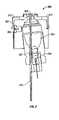
- FIG. 3shows a preferred embodiment of the sampling module according to the invention
- FIG. 4shows a low profile embodiment of the sampling module according to the invention
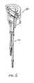
- FIG. 5provides a three-dimensional view of an optic system according to the invention
- FIG. 6provides a schematic diagram of the optic system of FIG. 5 according to the invention.
- FIG. 7provides a cross section of an optical probe from the optic system of FIG. 6 according to the invention.
- FIG. 8provides an alternative optical probe for the optic system of FIG. 5 according to the invention.
- FIG. 9shows mean second derivative spectra in the fat band area for a pool of test subjects according to the invention.
- FIG. 10shows a single filter embodiment of the sampling module according to the invention.
- FIG. 11shows an alternative embodiment of the sampling module according to the invention.
- FIG. 12shows noninvasive glucose predictions in a concentration correlation plot according to the invention
- FIG. 13shows an LED based embodiment of the sampling module according to the invention
- FIG. 14shows a possible LED reflector according to the invention.
- FIG. 15shows filter shapes optionally coupled to the LED according to the invention.
- the presently preferred embodiment of the inventionuses a sampling module coupled to a base module.
- the sampling moduleincludes an illumination system based upon an incandescent lamp.
- the base moduleincludes a grating and detector array.
- the base modulemay be connected to the sampling module through a communication bundle.
- the combined sampling module, communication bundle, base module, and associated electronics and softwareis referred to as a spectrometer and/or glucose analyzer.
- the sampling module 10is semi-permanently attached to the forearm of a subject 12
- a communication bundle 14carries optical and/or electrical signal to and/or from a base module 16 located on a table
- the communication bundlecarries power to the sampling module from the base module.
- FIG. 2A block diagram of the noninvasive glucose analyzer is provided in FIG. 2 .
- Essential elements of the glucose analyzerare the source 21 , guiding optics 14 before and/or after the sample for coupling the source to the sample and the sample to the detector(s) 23 , detector(s) and associated electronics 24 , and data processing system 25 .
- an optional optical filter 30 , light blocker 31 , and standardization material 32are shown. These components may also be positioned after the sample and before the detector. Variations of this simple block diagram are readily appreciated and understood by those skilled in the art.
- sampling modulemay include but are not limited to: a semi-permanent patient/instrument interface sampling module 10 incorporating at least one of a low profile sampling interface 34 , a low wattage stabilized source 21 in close proximity to the sampled site, an excitation collection cavity or optics, a guide, a preheated interfacing solution such as FLUORINERT (3M COMPANY, St. Paul Minn.), a temperature controlled skin sample, a mechanism for constant pressure and/or displacement of the sampled skin tissue, a photonic stimulation source, and collection optics or fiber.
- FLUORINERTFLUORINERT
- the sampling moduleprotrudes less than two centimeters from the skin measurement site.
- the sampling modulemay interface with a guide that may be semi-permanently attached to a sampling location on a human body.
- the guideaids in continuously and/or periodically physically and optically coupling the sampling module to the tissue measurement site in a repeatable manner with minimal disturbance.
- the guide in combination with the sampling moduleis responsible for pretreatment of the sample site for providing appropriate contact of the sampling device to the skin for the purpose of reducing specular reflectance, approaching and maintaining appropriate skin temperature variation, and inducing skin hydration changes.
- the sampling modulepreferably collects a diffusely reflected or transflected signal from the sampled region of skin.
- the base module or semi-remote systemincludes at least a wavelength selection device such as a grating 35 and a detector preferably a detector array with an optional wavelength reference standard 36 such as polystyrene and an optional intensity reference standard such as a 99% reflective Labsphere® disk.
- the remote systemis coupled to the sampling module via a communication bundle 14 that carries as least the optical signal and optionally power. Additionally, the communication bundle may transmit control and monitoring signal between the sampling module and the remote system.
- the remote systemhas at least one of an embedded computer 25 , a display 37 , and an interface to an external computer system. The remote system may be in close proximity to the guide element.
- the sampling module and base moduleare integrated together into a compact handheld unit.
- the communication bundleis integrated between the two systems.
- the housing 301is made of silicon.
- the lamp 302is a 0.8 W tungsten halogen source (Welch-Allyn 01270) coupled to a reflector 303 .
- a photodiode 309is used to monitor the lamp and to keep its output stable through the use of a lamp output control circuit, especially right after power-up.
- the reflector, and hence the incident lightis centered on an angle six degrees off of the skin's normal to allow room for a collection fiber.
- the lightis focused through a 1 mm thick silicon window 306 onto an aperture at the skin.
- the siliconoperates as a longpass filter.
- the illuminated aperture of the skinhas a 2.4 mm diameter.
- the patient sampling modulereversibly couples into the guide for reproducible contact pressure and sampling location. Magnets 312 are used in the guide to aid in the positioning of the probe, to ensure proper penetration of the probe into the guide aperture and to enable a constant pressure and/or displacement interface of the sampled skin 308 .
- the reversible nature of coupling the sampling module into the guideallows the sampling module to be removed and coupled to an intensity reference and/or a wavelength reference that have the same guide interface and are preferably housed with the base module.
- the preferred intensity referenceis a 99% reflective Labsphere® material and the preferred wavelength reference is polystyrene.
- the preferred sampling moduleuses a heater 309 for maintaining the skin at a constant temperature.
- a 600 ⁇ m detection fiber 310collects diffusely reflected light from the center of the silicon window.
- the detection fiberis coated in a manner to block source photons from penetrating through the cladding to the core.
- a metal sheathmay be placed around the detection fiber.
- the length of the detection fiberis 0.7 meters.
- the communication bundleincludes a power supply from the base unit.
- a blocking mechanismmay be included to allow the detection of detector dark current or baseline.
- the base moduleincorporating a grating, detected array, associated electronics, and associated software is coupled to the sampling module via this bundle. In this configuration, the sampling module extends roughly three inches from the arm.
- the base moduleresides on a table, the sampling module interfaces through a semi-permanently attached guide to the dorsal aspect of the forearm, and a communication bundle carries power and optical signal between the two modules.
- the base modulemay be worn on the person, for example on a belt.
- the sampling modulecould couple to any of a hand, finger, palmar region, base of thumb, forearm, volar aspect of the forearm, dorsal aspect of the forearm, upper arm, head, earlobe, eye, tongue, chest, torso, abdominal region, thigh, calf, foot, plantar region, and toe.
- the base moduleWhen the base module is on the table, it may plug into a standard wall outlet for power.
- the moduleWhen worn on the person, the module may be battery powered. When the base module is worn on the person, an optional docking station may be provided as described below for power and data analysis. It is noted here that the base module may couple directly to the sampling module without a communication bundle. The combined base module and sampling module may be integrated into a handheld near-IR based glucose analyzer that couples to the sampling site through an optional guide.
- the sampling module housing in the preferred embodimentwas selected to be constructed of silicon based upon a number of factors including but not limited to: providing a minimum of 6 O.D. blocking in the ultraviolet, visible, and near-IR from 700 to 1000 nm at a 1 mm thickness, low cost, manufacturability, durability, water resistance, and availability. It is recognized that it is the functionality of the housing that is important and that the above listed properties may be obtained through a variety of materials such as metals, composites, and plastics without altering the scope and intent of the invention.
- the 0.8 W tungsten halogen sourceis preferred for a number of reasons including but not limited to its power requirements, performance specifications such as color temperature, spectral output, and lifetime as well as on parameters such as ruggedness, portability, cost, and size. It is recognized that the source power is selected based upon the total net analyte signal generated and the amount of light reaching the detection system. It has been determined that the 0.8 W source in conjunction with the aperture and collection fiber of the preferred embodiment provides adequate signal and depth of penetration of the photons for the indirect determination of glucose using features in the 1150 to 1850 nm range. However, sources ranging from 0.05 W to 5 W may be used in this invention. As described in the alternative embodiment section, light emitting diodes (LED's) may be used as the source. The source is preferably powered by the base module through the connection cable described below. However, especially with the smaller sources a battery power supply may be incorporated into the sampling module.
- LED'slight emitting diodes
- a photodiodeis used in the preferred embodiment in conjunction with feedback control electronics to maintain the source at constant power output during data collection which is desirable during data acquisition.
- the photodiodeis placed before the order sorter (the silicon longpass filter), in order to detect visible light from the source.
- the preferred photodiodeis a silicon detector.
- Other less desirable photodiodesinclude but are not limited to InGaAs, InPGaAs, PbS, and PbSe. This arrangement of components is preferred due to the low cost, durability, and availability of detectors available in the visible and near-IR from 700 to 1000 nm where the long pass filter discussed below used later in the optical train blocks the optical signal used in the feedback loop.
- the control electronicsallow the source to be driven at different levels at different points in time during and prior to data acquisition.
- the sourceis initially run at a higher power in order to minimize the analyzer warm-up time.
- the photodiode and feedback electronicsare optional, but are used in the preferred embodiment. Many spectrometers are common in the art that do not use a separate detector for monitoring the source intensity.
- the source housing/reflector combination in the preferred embodimentwas selected based upon a number of factors including but not limited to: providing acceptable energy delivery to the sample site, reflectivity, manufacturability, ruggedness, size, cost, and providing appropriate heating/temperature control of the sample site.
- the specific reflector in the preferred embodimentis parabolic. The properties were optimized using standard ray trace software to image the lamp filament onto the aperture defining the sampling location. The optical prescription is tuned for a specific spectral range (1100 to 1900 nm) and the coatings are designed to reflect optimally in this range. It is recognized that the reflector may be elliptical or even spherical and that the mechanical and optical properties of the reflector may be varied without altering the scope and intent of the invention.
- the sourcemay shine light directly onto the sampled surface without the use of a reflector.
- a larger sourceis required.
- the specific focal distance of the reflectormay be varied, which impacts the overall dimensions of the interface without affecting functionality.
- a different substratemay be used as the reflector or metallized coatings such as gold, silver, and aluminum may be applied to the substrate.
- the source/housing reflector in the preferred embodimentmay be modified to bring in the source light nearly parallel to the skin surface.
- One objective of a low profile designis to maintain a sampling module that may be semi-permanently attached to the sampling site.
- a low profile sampling modulehas the benefit of increase acceptance by the consumer and is less susceptible to bumping or jarring during normal wear.
- a semi-permanent interfacewould allow consecutive glucose determinations in an automated continuous or semi-continuous fashion as described below.
- Light brought in at a low angle relative to the skinmay be turned into the skin with folding optics.
- a simple mirrormay be used; however, a focusing mirror is preferred in order to optimally couple light into the aperture.
- a representative embodimentis provided in FIG. 4 .
- a 600 ⁇ m fiber 40is used as the collection optic.
- the 600 ⁇ m fiberis fixed into the sampling module 41 .
- the sampling modulehas a connector for accepting a 300 ⁇ m fiber 42 that in turn couples to a slit prior to the grating in the base module.
- the coupling of the lightmay be done by lenses, which may be magnifying or de-magnifying or with folding mirrors 44 with appropriate attention to matching numerical apertures.
- An important concept in this designis that the second collection optic is readily removed from the sampling module allowing the sampling module to remain in contact with the arm.
- the quick connect opticallows the user to travel remotely from the base module until the next reading is desired.
- the inventionincludes guiding optics 14 before and/or after the sample for coupling the source to the sample and the sample to the detector(s).
- the guiding opticsmay be a cutaneous targeting optic system, as shown in FIGS. 5-9 .
- the above-mentioned co-pending application, J. Garside, S. Monfre, B. Elliot, T. Ruchti, F. Grochoki, Fiber optic illumination and detection patterns, shapes and locations for use in spectroscopic analysisU.S. patent application Ser. No. 09/415,389 (Oct. 8, 1999), now U.S. Pat. No. 6,411,373 (Jun.
- an optical probeis provided that is optimized to sample the cutaneous layer of a tissue sample, minimizing spectral interference contributed by the subcutaneous dermal layer.
- the optical interface 50incorporates an optic system 51 .
- FIG. 6shows a cross-section of the optic system 51 .
- the optic systemis composed of several smaller elements, referred to herein as probes.
- the optic systemincludes five probes.
- FIG. 7shows a detailed cross section of an individual probe.
- Each probeincludes, for example, twenty-two optical paths such as illumination fibers and ten detection fibers. Thus the entire bundle contains 110 fibers at the illumination end and fifty fibers at the detection end.
- the entire probeis preferably fabricated from a fiber such as ULTRASIL 200 (OFS OPTICS, INC., Norcross Ga.).
- FIG. 8shows an alternate configuration for optic system composed of three probes.
- the illumination end of the probepreferably contains ninety-three fibers and the detection end preferably contains sixteen fibers.
- FIG. 9shows the mean second derivative spectrum in the fat band area for test subjects of failed calibration, and for tests that led to some statistical significance in calibration.
- FIGS. 6-8are provided for illustrative purposes.
- Other combinations of optical paths and detection fiberscan be selected according to the principles described by Garside, et al., Ser. No. 09/415,389 (Oct. 8, 1999), now U.S. Pat. No. 6,411,373. Additionally, guided by the principles of the invention, one skilled in the art will readily conceive of other embodiments entirely consistent with the spirit and scope of the invention.
- a minimum distanceis maintained between the optical paths for the incident light and the detection fibers through the use of a spacer, as shown in FIG. 13 .
- the spaceris sized so that the maximum penetration distance of the incident radiation is greater than the radial dimension of the spacer.
- the radial dimensionranges from approximately 50 ⁇ m to approximately 3000 ⁇ m. More particularly, the radial dimension can be any of: 100, 200, or 300 ⁇ m.
- the optical interface of FIGS. 5-8finds application in other applications in addition to the current described embodiments.
- the optical interfacecan be used in the detection of other analytes.
- the optical interfacecan be deployed in other settings that require coupling of a light source and a sample.
- the optical sourceis a heat source.
- Skin temperatureis an important variable in near-IR noninvasive glucose determination.
- a thermistor 45 sensing the sampling module or patient skin temperature and feeding this information back to the source via feedback electronics prior to samplingmay be used prior spectral data acquisition in order elevate the skin temperature to a desirable sampling range such as 30 to 40 degrees centigrade.
- the inclusion of a heater, thermistor, and associated feedback electronicsare optional to this invention.
- the skin temperaturemay be measured spectrally by the relative positions of water, fat, and protein in an acquired near-IR spectrum or through a multivariate analysis.
- an optical filteris placed between the source and the sampling site.
- the optical filteris silicon.
- the silicon windowwas selected based upon a number of factors. One factor is that silicon behaves as a longpass filter with blocking to at least six optical density units with a 1 mm thickness from the ultraviolet through the visible to 1000 nm.
- the longpass characteristic of siliconacts as an order sorter benefiting the grating detector combination in the base module.
- the longpass characteristic of siliconremoves unwanted photons in the ultraviolet, visible, and near-IR that would heat the skin at unwanted depths and to undesirable temperatures due to conversion of the light into heat via the process of absorbance. Instead, the silicon is heated by these photons resulting in maintenance of skin temperature near the surface via conduction.
- siliconoffers excellent transmissive features in the near-IR over the spectral region of interest of 1150 to 1850 nm.
- siliconis the same material as the source housing and source reflector. Therefore, a single molding or part may be used for all three components.
- a silicon windowis in contact with the skin to minimize specular reflectance.
- this windowis anti-reflection coated based upon properties of air on the photon incident side and based upon the optical properties of the coupling fluid on the skin surface side of the optic.
- the longpass filtermay be placed after the source but not in contact with the skin.
- the filtermay be placed in or about the pupil plane.
- photons removed by the filter that result in the heating of the filterdo not result in direct heating of the sample site via conduction. Rather, the much slower and less efficient convection process conveys this heat. This reduces the risk of over heating the skin.
- two filtersmay be placed between the source and the skin. These filters may or may not be the same. The first filter removes heat as above. The second filter reduces spectral reflectance as above.
- the order sorter nature of the longpass filteris central.
- Siliconremoves light under 1050 nm. This allows a grating to be used in the 1150 to 1850 nm region without the detection of second or higher order light off of the grating as long as the longpass filter, silicon, is placed before the grating. Therefore, in the third configuration the longpass filter may be after the sample.
- a silicon longpass filteris used.
- the filtersmay be coated to block particular regions such as 1900 to 2500 nm, antireflection-coated in order to match refractive indices and increase light throughput, and/or used in combination with other filters such as shortpass filters.
- One configurationcoats the silicon with a blocker from 1900 to 2500 nm. This has the advantage of removing the largest intensity of the blackbody curve of a typical tungsten halogen source that is not blocked by silicon or in the desirable region of 1150 to 1850 nm. This blocking band may cover any region from about 1800 nm on up to 3000 nm.
- Another configurationis a silicon longpass filter used in combination with an RG glass such as RG-850 that cuts off at about 2500 nm.
- the combinationprovides a very cost effective and readily reproduced bandpass filter passing light from approximately 1100 to 2500 nm.
- this filter combinationmay be used in conjunction with a coating layer such as a blocker from 1900 to 2500 nm in order to provide a bandpass from 1100 to 1900 nm.
- a coating layersuch as a blocker from 1900 to 2500 nm in order to provide a bandpass from 1100 to 1900 nm.
- FIG. 10An alternative embodiment of the source/reflector/filter is shown in FIG. 10 .
- siliconis shaped into a parabolic optic 100 surrounding part of the source 101 .
- the outside of the siliconis coated with a reflector 102 such as gold.
- This embodimentallows a low profile source coupled to the skin. The total height off of the skin may be less than 1 cm with this configuration.
- the shape of the silicon opticin conjunction with coating the outside of the silicon with a reflective material such as gold allows efficient coupling of the photons into the skin.
- An additional optional protective coating over the reflector materialallows the silicon optic to also act as a housing for the sampling module with the benefits of silicon listed above.
- the initial surface of the siliconremoves the higher energy photons that results in heating of the source optics prior to contact with the skin.
- the later part of the silicon (near the skin) in combination with a collection fiberacts as a mechanism for reducing specular reflectance.
- This configurationeliminates the optional two filter system as heat and spectral reflectance are dealt with in one optic.
- the siliconis acting as a turning optic to allow a very low profile sampling module, as a longpass filter, as an order sorter, as a heat blocker, as a spectral reflectance blocker, and as a very manufacturable, cheap, and durable component.
- FIG. 11An alternative embodiment of the source/reflector/filter is shown in FIG. 11 .
- the source filament 110is wrapped around a collection fiber 111 .
- the reflectornow directs light into the skin aperture through an optic 112 .
- the opticmay be surface coated for reflectance on the incident light surface.
- the reflectormay be transmissive and the outer surface of the reflector may be reflectively coated. As above, this allows the reflector to act as the housing.
- there exists a filter adjacent to the skin that in conjunction with a collection optic, fiber, or tube adjacent to the skinresults in the blocking of specular reflectance.
- An alternative embodimentcombines a broadband source with a single element detector without the use of a grating.
- an interferometercomposed of two parallel, highly reflecting plates separated by an air gap may be used.
- One of the parallel platesmay be translated mechanically such that the distance between the plates varies.
- thisis a Fabry-Perot interferometer.
- the mirror distanceis fixed and adjusted for parallelism by a spacer such as invar or quartz, the system is referred to as a Fabry-Perot etalon.
- This systemallows narrow excitation lines as a function of time. Therefore, no dispersive element is required and a single element detector may be used.
- the interferometermay be placed in one of multiple positions in the optical train.
- the illuminated aperture of the skinhas a 2.4 mm diameter.
- the aperture in the preferred embodimentwas selected based upon a number of factors including but not limited to: providing optical pathlengths within the sample for indirectly monitoring glucose concentrations within the body, providing acceptable energy delivery to the sample site, and providing appropriate heating/temperature control of the sample site.
- a fiber optic collection fiberis placed in the center of this illumination area. This allows the incident photon approximately 1 mm of radial travel from the point of illumination to the collection fiber. This translates into depths of penetration that probe water, fat, and protein bands as well as scattering effects that may be used for the indirect determination of glucose. It is recognized that the dimensions of the aperture need not be the exact dimensions of the preferred embodiment.
- An important aspectis the ability to deliver photons to a skin tissue, allow them to penetrate to depths that allow an indirect measurement of glucose, and detect those photons.
- the aperture of 2.4 mmmay be varied.
- the apertureprovides an outer limit of where photons from the source may penetrate the skin. This in turn defines the largest depth of penetration and optical pathlengths observed.
- the aperturemay be varied from 1.2 to 5 mm in diameter, the 2.4 mm diameter allows collection of spectra with excellent features for the indirect measurement of glucose. At smaller apertures, the average depth of penetration of the collected photons decreases. Therefore, variation of the aperture affects the net analyte signal of the sampled tissue. Varying aperture shapes are possible as the shape affects the distribution of photons penetration depth and optical pathlength.
- the indirect determination of glucosemay be performed off of sample constituents such as fat, protein, and water that are distributed as a function of depth. Therefore, the magnitude of the indirect signal varies with the aperture.
- multiple excitation sites and collection sitesare possible. This could aid, for example, in sampling a representative section of the skin. For example, if one probe was located on a hair follicle, the others may be used independently or in conjunction with the first site in order to acquire the analytical signal necessary to determine glucose.
- the entire patient interface modulecouples into a guide that is semi-permanently attached to the skin with a replaceable adhesive.
- the guideaids in sampling repeatability.
- the guideis intended to surround interfacing optics for the purpose of sampling in a precise location. Typically this is done with an interface surrounding the interface probe.
- the guideis attached for the subject's waking hours.
- a guidemay be attached in a more permanent fashion such as for a week or a month, especially in continuous monitoring glucose analyzers discussed below.
- the guideallows improved precision in sampling location. Precision in sampling location allows bias to be removed if a process such as mean centering is used in the algorithm. This is addressed in the preprocessing section below.
- the guideallows for a more constant pressure/constant displacement to be applied to the sampling location which also enhances precision and accuracy of the glucose determination. While the guide greatly enhances positioning and allows associated data processing to be simpler and more robust, the guide is not an absolute requirement of the sampling module.
- magnetsare used to aid in a user friendly mechanism for coupling the sampling module to the sampled site. Further, the magnets allow the guide to be reversibly attached to the sampling module. Further, the guide aids in the optical probe adequately penetrating into the guide aperture. In addition, the magnets allow a constant, known, and precise alignment between the sampling probe and the sampled site. In the preferred embodiment two magnets are used, one on each side of the sampled site, in order to enhance alignment. One or more magnets may provide the same effect.
- the magnetsmay be electrically activated to facilitate a controlled movement of the probe into the guide aperture and to allow, through reversal of the magnet poles, the probe to be withdrawn from the guide without pulling on the guide.
- the guidemay optionally contain a window in the aperture that may be the longpass/bandpass filter.
- the aperturemay be filled with a removable plug.
- the contact of a window or plug with the skinstabilizes the tissue by providing the same tissue displacement as the probe and increases the localized skin surface and shallow depth hydration.
- use of a contact windowallows a continuous barrier for proper hydration of the sampling site and a constant pressure interface.
- the use of a plug or contact windowleads to increased precision and accuracy in glucose determination by the removal of issues associated with dry or pocketed skin at the sampling site.
- the guidemay optionally contain any of a number of elements designed to enhance equilibration between the glucose concentration at the sampling site and a capillary site, such as the fingertip. Rapidly moving glucose values with time can lead to significant discrepancies between alternate site blood glucose concentration and blood glucose concentration in the finger. The concentration differences are directly related to diffusion and perfusion that combine to limit the rate of the equilibrium process. Equilibrium between the two sites allows for the use of glucose-related signal measured at an alternate site to be more accurate in predicting finger blood glucose values.
- a number of optional elementsmay be incorporated into the sampling module and/or guide to increase sampling precision and to increase the net analyte signal for the indirect glucose determination. These optional elements are preferably powered through the base module and connection cable described below but may be battery operated. Equalization approaches include photonic stimulation, ultrasound pretreatment, mechanical stimulation, and heating. Notably, equilibration of the glucose concentration between the sampled site and a well-perfused region such as an artery or the capillary bed of the fingertip is not required. A minimization of the difference in glucose concentration between the two regionsl aids in subsequent glucose determination.
- the guidemay optionally contain an LED providing photonic stimulation about 890 nm, which is known to induce capillary blood vessel dilation. This technique may be used to aid in equilibration of alternative site glucose concentrations with those of capillary blood. By increasing the vessel dilation, and thereby the blood flow rate to the alternate site, the limiting nature of mass transfer rates and their effect on blood glucose differences in tissue is minimized. The resulting effect is to reduce the differences between the finger and the alternate site blood glucose concentrations.
- the preferred embodimentuses (nominally) 890 nm LED's in an array with control electronics set into the arm guide. The LED's can also be used in a continuous monitoring application where they are located in the probe sensing tip at the tissue interface. Due to the periods of excitation required for stimulation, the 890 nm LED is preferably powered by a rechargeable battery in the guide so that the LED may be powered when the communication bundle is not used.
- the guidemay optionally contain an apparatus capable of delivering ultrasound energy into the sample site. Again, this technique may be used to aid in equilibration of alternative site glucose concentrations with those of capillary blood by stimulating perfusion and/or blood flow.
- the guidemay optionally contain an apparatus that provides mechanical stimulation of the sampled site prior to spectral data acquisition.
- an apparatusthat provides mechanical stimulation of the sampled site prior to spectral data acquisition.
- One exampleis a piezoelectric modulator that pulses in an out relative to the skin surface a distance of approximately 20 to 50 ⁇ m in a continuous or duty cycle fashion.
- the guidemay optionally contain a heating and/or cooling element, such as a strip heater or an energy transfer pad.
- Heatingis one mechanism of glucose compartment equilibration.
- These elementsmay be used to match the core body temperature, to manipulate the local perfusion of blood, to avoid sweating and/or to modify the distribution of fluids among the various tissue compartments.
- sampling modulecan interface directly to a skin sampling without the use of a guide.
- a coupling fluidis used to efficiently couple the incident photons into the tissue sample.
- the preferred coupling fluidis the perfluoro compound FLUORINERT. Different formulations are available including FC-40 and FC-70. FC-40 is preferred. While many coupling fluids are available for matching refractive indices, FLUORINERT is preferred due to its non-toxic nature when applied to skin and due to its absence of near-IR absorbance bands that would act as interferences.
- the coupling fluidis preheated to between 90 and 95° F., preferably to 92° F. Preheating the coupling fluid minimizes changes to the surface temperature of the contacted site, thus minimizing spectral changes observed from the sampled tissue.
- the coupling fluidmay be preheated using the source energy, the optional sample site heater energy, or through an auxiliary heat source. Preheating FC-70 is preferable due to its poorer viscosity. The preheated FC-70 is not as likely to run off of the sample site. Automated delivery prior to sampling is an option. Such a system could be a gated reservoir of fluorinert in the sample module. Manual delivery of the coupling fluid is also an option, such as a spray bottle delivery system. Coverage of the sample site is a key criteria in any delivery system.
- the sampling siteis the dorsal aspect of the forearm.
- the volar and ventral aspect of the forearmare excellent sampling locations.
- the guidemay be attached to other sampling locations such as the hand, fingertips, palmar region, base of thumb, forearm, upper arm, head, earlobe, chest, torso, abdominal region, thigh, calf, foot, plantar region, and toes. It is preferable but not required to sample regions of the skin that do not vary due to usage as with the fingertips or near joints, change with time due to gravity like the back of the upper arm, or have very thick skin such as the plantar region, or abdominal region.
- collection opticsThere are a number of possible configurations for collection optics.
- lightis incident to the sample through the longpass filter which is in contact with the skin.
- the longpass filterwhich is in contact with the skin.
- a collection fiberis placed into the hole in contact with the skin. This configuration forces incident photons into the sampled skin prior to collection into the fiber optic. If the fiber optic were merely pushed up against the filter, then light could bounce through the filter directly into the collection fiber without entering the skin resulting in a spectral reflectance term.
- the signal(or rather absence of observed intensity) at the large water absorbance bands near 1450, 1900, and 2500 nm may be used to determine when the apparatus is in good spectral contact with the sampled skin.
- the preferred collection opticis a single 600 ⁇ m detection fiber. It is recognized that the hole and the fiber may be altered in dimension to couple in another sized fiber such as a 300 ⁇ m detection fiber. As those skilled in the art will appreciate, the fiber diameter is most efficient when it is optimally optically coupled to the detection system. Therefore, as detector systems slits and detector element sizes are varied, the collection optics should also be varied.
- the center collection fiber of 600 ⁇ m combined with the aperture of 2.4 mmis related to a central fiber collecting incident light from a bundle.
- the collection opticis not necessarily limited to a fiber optic. Additional configurations include but are not limited to a light pipe or a solid piece of optical glass.
- the collected signalis turned 90° off axis to send the signal roughly parallel to the arm in order to minimize the height of the sampling module. This may be accomplished by such common means as a folding mirror or bending of a fiber optic, as described above.
- the collected lightis coupled to a second collection that connects at its opposite end to the base module.
- the purpose of this configurationis to allow the sampling module to be worn on the person without the bulk of the rest of the spectrometer here referred to as the base module.
- a quick connect connectoris used to allow rapid connection of the base module to the sampling module in a reproducible and user friendly fashion.
- the connecting cablecarries at least the optical signal.
- the connection cablealso carries power to the source and optional elements, such as the thermistor, heater, or sample compartment glucose concentration equilibration apparatus. This connector also allows the diameter of the collection fiber to be changed.
- the 600 ⁇ m collection fibermay be downsized to a 300 ⁇ m connection fiber with appropriate attention to coupling optics and numerical apertures obvious to those skilled in the art.
- connection fiberSome advantages of the smaller diameter connection fiber are described here.
- the smaller diameter fiberhas a tighter bend radius.
- the fibercan be made of appropriate dimension for coupling to the slit.
- the smaller diameter fiberis less susceptible to breakage. An additional consideration is cost.
- collection/detection elementsmay be recessed away from the window in order to avoid the direct detection of surface reflectance. It is further recognized that coupling fluids may be used to increase the angle of collection to the detection element.
- the base moduleincludes at least a spectrometer (grating and detector system).
- the gratingis optimized to deliver peak energy about 1600 nm.
- the detectoris an InGaAs array covering the range of 1100 to 1900 nm.
- a main purpose of the spectrometeris wavelength separation and detection. Variations in the grating/detector system are readily understood by those skilled in the art.
- a broadband sourceis combined with a detector array without the use of a dispersive element.
- filtersare placed in from the detectors.
- One type of filterare thin dielectric films, such as in Fabry-Perot interference filters. These filters may be placed into a linear, bundle, or rectangular pattern depending upon how the light is coupled to the detector. For example, a slit may be used in conjunction with a rectangular array of filters and detectors. Alternatively, a fiber may be used in conjunction with a bundle of filters and associated detectors.
- Another type of filteris a linear variable filter. For example, a linear variable filter may sit in from of a linear array of filters. Many variations on these optical layouts are known to those skilled in the art.
- the Power/Control Modulemay be coupled to the user's belt or other location other than the measurement site.
- the patient interface modulecontains a battery and two-way wireless communication system.
- the Control/Power modulemay be carried by the patient.
- a handheld computer or Palm computing platformcan be equipped with a two-way wireless communication system for receiving data from the patient interface module and sending instructions. The computer system then provides the system with analysis capabilities.
- the base modulecontains a battery and two-way wireless communication system.
- the Control/Power moduleis contained a remote location that is either carried by the patient or not.
- a handheld computer or palm computing platformcan be equipped with a two-way wireless communication system for receiving data from the patient interface module and sending instructions. The computer system then provides the system with analysis capabilities.
- the Control/Power Modulecontains the control electronics, power system, batteries, embedded computer and interface electronics.
- Control electronicsprovide a means for initiating events from the embedded or attached computer system and interfacing the detector electronics (amplifiers) which provide a voltage that is related to the detected light intensity. Digitizing the detected voltage through the use of an analog-to-digital converter is performed. The signals detected are used to form a spectrum which is represents the diffusely reflected and detected light intensity versus wavelength.
- historical measurementsare made available through a display and/or an external communication port to a computer or computer system, e.g. a Palmtop.
- the measurement and ancillary informationis transferred to a remote display and receiving unit, such as a handheld computer or stand-alone display module through a wireless communication.
- a display and receiving unitmay be incorporated into a watch, pen, personal desktop assistance, cell phone, or blood glucose monitoring device.
- variation of one componentmay affect optimal or preferred characteristics of other components.
- variation in the sourcemay affect the quality or design of the reflector, the thickness of the filter, the used aperture size, the time or power requirements for maintaining or heating the skin and/or FLUORINERT, and the diameter of the collection fiber.
- changing another componentsuch as the collection fiber diameter impacts the other elements.
- one or more components of the spectrometermay be changed without altering the scope of the invention.
- Important regions to detectare permutations and combinations of bands due to water centered about 1450, 1900, or 2600 nm, protein bands centered about 1180, 1280, 1690, 1730, 2170, or 2285 nm, fat bands centered about 1210, 1675, 1715, 1760, 2130, 2250, or 2320 nm, or glucose bands centered about 1590, 1730, 2150, and 2272 nm.
- a preferred physical orientation of the spectrometeris in a vertical position. For example, when sampling on the dorsal aspect of the forearm when the palm is face down on a support it is preferable for the sampling module to come down onto the arm from above. This allows the weight of the sampling module to be reproducible.
- Near-infrared devicesare composed of optical and mechanical components that vary due to manufacturing tolerances, vary in optical alignment, and change with time due to mechanical factors such as wear and strain, and environmental factors such as temperature variation. This results in changes in the x-axis of a given spectrometer with time as well as instrument-to-instrument variation.
- a calibration modelis used to extract information about a sample, such as the glucose concentration in the body, these instrument related changes result in wavelength uncertainty that reduces the accessibility of the signal related to the property of interest. These variations also degrades the device accuracy when a calibration model is transferred from one instrument to another.
- a system for standardizing the wavelength axis of near-IR optical systems that measures light at a multiplicity of wavelengthsis described in this section.
- the preferred embodimentis that presented in FIG. 2 .
- the system described in this sectionmay be used with the instrument configurations described in the remainder of this document.
- the spectrometer systemdetects the transmitted or reflected near-infrared radiation from the sample within a specified wavelength range and the analyzer determines the absorbance at various wavelengths after a standardization procedure.
- Methods for standardizing the x-axis of a spectrometer based systemrely on a comparative analysis of a master and slave spectra of a standardization material. A material with absorption bands in the targeted wavelength region is used for determining the x-axis.
- the reference or standard absorbance bandsare reasonably sharp, stable, and distributed across the wavelength region of interest (1100 to 1900 nm).
- Common materials for this purposeare polystyrene, erbium oxide, dysprosium oxide, and holmium oxide though a large number of plastics may be used.
- Internal polystyrenehas been used as a reference in the FOSS, formerly NIRSystems spectrometers. However, in these systems, polystyrene is used in conjunction with an actuated rotating grating and a single detector. In the preferred embodiment of this invention no actuated grating is used.
- the material used for standardizationmay be measured external to the spectrometer system with an external mounting system.
- the material mounted in a separate standard mounting system external to the spectrometermust be placed on the device by the user at designated time periods. This process is subject to positioning error and increases the complexity of the measurement protocol from the standpoint of the user. This is particularly a problem in consumer oriented devices, such as non-invasive glucose sensors, in which the user may not be technically oriented.
- the referencemay be continuously mounted internal to the instrument in a separate light path. In this configuration, the internal wavelength standard may be measured simultaneously with the sample. Alternatively, the reference may be moved through an actuator into the main optical train at an appropriate time, optionally in an automated process. In either of these systems, the reference spectrum may be collected in transmittance of reflectance mode. However, it is preferable to collected an external reference in diffuse reflectance mode. For example a polystyrene disk placed at an angle to the incident light to minimize specular reflectance may be backed by a reflector such as a LABSPHERE reference. For an internal reference, a similar arrangement may be used, but a transmittance spectrum is preferred.
- the wavelength standardization systemincludes associated methods for measurement of a reference spectrum and a (wavelength) standardization spectrum through the spectroscopic measurement of a non-absorbing material and a material with known and immutable spectral absorbance bands respectively.
- the spectrum of the standardization materialis used in-conjunction with an associated method for standardizing the x-axis of sample spectra that are collected subsequently.
- the methodincludes a master spectrum of the standardization material and a method for determining the discrepancy between the master and instrument standardization spectrum.
- the master spectrum and the wavelength regionsare stored in nonvolatile memory of the instrument computer system.
- One method of calculating the phase difference or x-axis shift between the master and slave spectrais through the use of cross correlation.
- one or more windows across the spectrum the x-axis phase shift between the master and acquired spectrumare determined through a cross-correlation function after removing instrument related baseline variations.
- the phase shiftis used to correct (standardize) the x-axis of the acquired spectrum to the master spectrum.
- Other approachesinclude interpolation or wavelet transformation.
- preprocessingoccurs.
- the detected spectrummay be processed through multiple preprocessing steps including outlier analysis, standardization, absorbance calculation, filtering, correction, and application to a linear or nonlinear model for generation of an estimate (measurement) of the targeted analyte or constituent which is displayed to the user.
- the preprocessing step of bias correcting the spectral data collected in one or both of the X (spectra) and Y (glucose concentration) datamay have a reference glucose concentration associated with it. This glucose concentration may be used as a bias correction for glucose determinations collected until subsequent calibration.
- the first spectrum of the daymay be used to adjust calibration components from the X block.
- the guideallows the same sampling location to be obtained until the guide is removed. This directly impacts the use of the first spectrum and reference glucose concentration to adjust the model in terms of preprocessing and subsequent model application.
- Subsequent data analysismay include a soft model or a calibration such as PCR or PLS.
- a methodhas been invented for calibrating the device to an individual or a group of individuals based upon a calibration data set.
- the calibration data setis comprised of paired data points of processed spectral measurements and reference biological parameter values.
- the reference valuesare one or more of the following: finger capillary blood glucose, alternate site capillary blood glucose, i.e. a site on the body other than the finger, interstitial glucose or venous blood glucose.
- the calibration datais subject to optimal sample selection to remove outliers, data correlating to ancillary factors and data with excessive variation.
- Spectral measurementsare preprocessed prior to calibration through filtering and scattering correction and normalized to a background template collected each time the guide system is attached to the skin tissue. Measurements are performed after preprocessing data collected subsequent to calibration as discussed above through the calibration or model to measure the variation of the biological parameter relative to its value at the time the guide was attached. The scope of these techniques was addressed in the prior art section and are well known to those skilled in the art.
- results of a study using a noninvasive glucose analyzerare presented here.
- the studyused a custom built noninvasive near-IR glucose analyzer.
- the analyzeris conceptually as presented in the preferred embodiment with components including a tungsten halogen source, a back-reflector, a bandpass optical filter, a fiber optic illumination bundle, a guide, a fluorinert coupling fluid, a guide, an aperture, a forearm sampling site, a collection fiber, a slit, a dispersive grating, and an InGaAs array detector though the spectrometer was larger in overall dimensions than in the preferred embodiment.
- the miniaturized sampling modulehas been demonstrated to deliver equivalent energy to the sample site.
- a calibration modelwas built.
- a subsequent prediction data setwas initiated two weeks after all parameters were fixed in the calibration model.
- Subsequent prediction data(spectra) were collected with two spectrometers on seven people over a period of seven weeks.
- Preprocessingincluded a Savitsky-Golay first derivative with twenty-seven points and mean centering.
- a PLS modelwas applied with a fifteen factor model to the resulting data over a range of 1200 to 1800 nm.
- a total of 976 glucose determinationswere made.
- the outlier analysis programwas automated. The results are presented in FIG. 12 in a concentration correlation plot overlaid with a Clarke error grid. Overall, 99.9% of the glucose predictions fell into the ‘A’ or ‘B’ region of the Clarke error grid. These glucose predictions are considered clinically accurate.
- the base moduleis integrally connected to the docking station.
- the docking stationincludes a computer and a glucose management center.
- the glucose management systemmay keep track of events occurring in time such as glucose intake, insulin delivery, and determined glucose concentration. These may be graphed with time or exported to exterior devices, such as a doctor's computer.
- a processfor estimating the precision of the measurement through a statistical analysis of repeated or successive measurements.
- a methodis implemented for determining when the biological parameter is close to a preset level through a statistical estimate of the confidence limits of a future analyte prediction.
- the predictionis made through a simple slope, e.g. change in the biological parameter over the change in time, estimate based on an exponentially moving average and the confidence limits are based upon the estimate of precision.
- the predictionis made through a standard time series analysis.
- An alarmis invoked if the associated present alarm level is within the confidence interval of a future biological parameter prediction.
- This processis used, for example, to detect the potential for hypoglycemia in diabetics in the near future, e.g. within 10-30 minutes.
- the processis used to detect potential outliers through a determination of the statistical consistency of a particular measurement with its expected value.
- Continuous or semi-continuous measurementsmay be taken when the sampling module is in contact with the sampling site. Measurements of a biological parameter that are made at short intervals relative to the change in the biological parameter such that the measurement process is continuous. In the preferred embodiment, measurements may be made every six seconds. Realistically, the glucose concentration does not change to a measurable level within six seconds. Therefore, readings taken at a less frequent interval such as every 1, 5, 10, 20, 30, or 60 minutes can be made. Readings taken at this interval are still referred to as continuous and/or semi-continuous. The continuous readings may be performed in an automated fashion.
- the guidecan remain attached to the individual while the rest of the system is intermittently attached at particular intervals to make continuous or semi-continuous readings.
- An element of the inventionis the use of the time based information and trends to perform other functions such as estimate of the precision, confidence intervals and prediction of future events.
- a processfor estimating the precision of the measurement through a statistical analysis of repeated or successive measurements.
- a methodis implemented for determining when the biological parameter is close to a preset level through a statistical estimate of the confidence limits of a future analyte prediction.
- the predictionis made through a simple slope, e.g. change in the biological parameter over the change in time, estimate based on an exponentially moving average and the confidence limits are based upon the estimate of precision.
- the predictionis made through a standard time series analysis.
- An alarmis invoked if the associated present alarm level is within the confidence interval of a future biological parameter prediction.
- This processis used, for example, to detect the potential for hypoglycemia in diabetics in the near future, e.g. within 10-30 minutes.
- the processis used to detect potential outliers through a determination of the statistical consistency of a particular measurement with its expected value.
- Control/Power. modulecan be secured without disturbing the sample site the two modules are merged into one that are attached to the subject through the guide interface system. Finally, when the biological parameter is slowly varying, the guide can remain attached to the individual while the rest of the system is intermittently attached at particular intervals.
- a linkis disclosed to an insulin delivery system.
- the monitored biological parameteris glucose
- a linkis provided to an insulin delivery system to provide a feedback mechanism for control purposes.
- the linkis either a direct or a wireless connection.
- a communication systemis provided for transmitting the patient's monitored glucose levels to his physician.
- a primary alternative embodiment of the inventionincludes two main modules: a sampling module and base module connected though a communication bundle.
- the modulesare as described in the preferred embodiment with the exception of the source and the associated wavelength selection/detection components.
- the spectrometer systemuses LED's to both provide near-infrared radiation to the sample and to perform wavelength selection over predefined wavelength ranges. This embodiment has the significant advantage of not requiring a dispersive element or interferometer based system for the purpose of wavelength selection. Rather, each LED provides near-infrared radiation over a band of wavelengths and thereby gives the necessary means for wavelength selection.
- the wavelengths of the LED'sare selected specifically to optimize the signal-to-noise ratio of the net analyte signal of the target analyte and are arranged at various distances with respect to the detection elements to provide a means for sampling various tissue volumes for the purpose of averaging and the determination of a differential measurement.
- the LED'sare sequentially energized one at a time and/or in groups to obtain various estimates of the diffuse reflectance of various tissue volumes at specific wavelengths or bands of wavelengths.
- the LED'scan be pulsed to provide short measurements with high signal-to-noise ratios. This provides greater illumination intensity, while avoiding photo heating of the sampled tissue volume.
- the LED'scan be modulated at a particular duty cycle and frequency to provide a means for removing additive noise and simultaneous measurement of multiple wavelengths.
- the wavelengths of the LED(s)are selected specifically to optimize the signal-to-noise ratio of the net analyte signal of the target biological parameter and are arranged at various distances with respect to the detection elements to provide a means for sampling various tissue volumes for the purpose of averaging and the determination of a differential measurement.
- the LED'sare sequentially energized one at a time and/or in groups to obtain various estimates of the diffuse reflectance of various tissue volumes.
- the LED'scan be pulsed to provided short measurements with a high signal-to-noise ratio while avoiding photo heating of the sampled tissue volume.
- the LED'scan be modulated at a particular duty cycle and frequency to provide a means for removing additive noise and simultaneous measurement of multiple wavelengths.
- the remainder of the spectrometerremains as in the preferred embodiment and its species.
- the LED'smay be stabilized with control electronics, optics may be used to guide the source intensity to the sampled aperture, a guide may be used, a coupling fluid may be used, temperature stabilization of the source and or sample may be used, collection optics integrate with the sampled skin directly, a communication bundle may be employed, and a base module is used with or without a docking station.
- the detectormay stare directly at the tissue.
- the LED'smay illuminate the sample directly, as in FIG. 13 .
- a coupling fluid 134as disclosed above, is shown between the device and the tissue sample.
- An optional mixing chamber with a reflective surfacemay be used between the LED's 130 and the optical window 131 to provide a nearly uniform distribution onto the tissue region 132 surrounding the detection fiber 133 .
- a spacer 135may also be provided between the fiber and the LED's.
- the LED'sare designed with a bandwidth enabling the measurement, and the LED's are arranged in a manner that allows the sampling and detection of a particular tissue volume at a particular band of wavelengths.
- Each LEDmay be recessed into a material 141 having a reflective surface 140 as shown in FIG. 14 .
- a mixing chamberis present as shown in FIG. 13 with the filter inserted in the place of the optical window. This allows the LED's to be used in much the same way as a broadband source.
- the illumination-to-detection distancemay be used for measurement purposes so the mixing chamber is removed and the LED's are put in close proximity or even touching the overall sampling site via optional filters.
- the distance from the illumination spot of the LED to the collection opticsis known. This allows the average depth of penetration of the photons and average pathlength to be known. This allows wavelength dependent scanning of depth and radial variation from the collection spot, and allows wavelength specific information to be used in an indirect reading of the glucose concentration.
- groups of LED'sare employed with each group associated with a single filter type, more than one physical filter may be necessary.
- the LED'sare arranged at distances surrounding the detection fiber and energized according to a strategy enabling the detection of light associated with different wavelength bands and different illumination to detection distances (see FIG. 15 ).
- the groups of LED'sare arranged in annuli (rings) at specific distances surrounding the detection fiber.
- the filtersare arranged in rings surrounding the detection fiber and covering the associated LED's. Each annular ring of the filter may have its own filter characteristics.
- groups of LED'sare arranged in wedges surrounding the detection fiber.
- the filtersmay be of a wedged or triangular shape and are arranged to cover their associated LED's. Each wedge filter may have its own filter characteristics.
- each LED or group of LED'shas an associated optical filter that is used to limit the bandwidth of emitted light.
- a different filteris mounted such that the light emitted and delivered to the sample from the LED passes through the filter.
- the filter associated with an LEDis designed with a specific bandwidth and is centered on a particular wavelength that is within the native bandwidth of the LED.
- groups of LEDscan be associated with the same filter. Through alternate energization of the LEDs or by modulating each LED or LED group at different frequencies (and demodulating after detection), narrow wavelength bands on the order of 5-100 nm can be distinguished and measured through a single element detector.
- the LED'shave a bandwidth relatively broader than the net analyte and interference signals.
- the light collected by the detection fiberis passed through a slit and imaged onto dispersive element which disperses the band of detected light onto an array of detector elements.
- optical filters on the LED'sare not employed.
- the LED'sare used in a spectrometer without a dispersive element and a single element detector.
- thin dielectric filmsare used as in Fabry-Perot interference filters.
- a filteris associated with each LED.
- an interferometercomposed of two parallel, highly reflecting plates separated by an air gap may be used. One of the parallel plates may be translated mechanically such that the distance between the plates varies.
- thisis a Fabry-Perot interferometer.
- the mirror distanceis fixed and adjusted for parallelism by a spacer such as invar or quartz, the system is referred to as a Fabry-Perot etalon. Both cases allow narrow excitation lines and may be used by sequentially firing the LED's as above.
- the spectroscopic measurement systemincludes a source of near-infrared radiation, a wavelength selection system, an interface to the patient, photon guiding optics, and a detector.
Landscapes
- Health & Medical Sciences (AREA)
- Life Sciences & Earth Sciences (AREA)
- Physics & Mathematics (AREA)
- Pathology (AREA)
- General Health & Medical Sciences (AREA)
- Engineering & Computer Science (AREA)
- Veterinary Medicine (AREA)
- Biophysics (AREA)
- Biomedical Technology (AREA)
- Heart & Thoracic Surgery (AREA)
- Medical Informatics (AREA)
- Molecular Biology (AREA)
- Surgery (AREA)
- Animal Behavior & Ethology (AREA)
- Public Health (AREA)
- Spectroscopy & Molecular Physics (AREA)
- Optics & Photonics (AREA)
- General Physics & Mathematics (AREA)
- Chemical & Material Sciences (AREA)
- Analytical Chemistry (AREA)
- Biochemistry (AREA)
- Immunology (AREA)
- Emergency Medicine (AREA)
- Dermatology (AREA)
- Dentistry (AREA)
- Oral & Maxillofacial Surgery (AREA)
- Investigating Or Analysing Materials By Optical Means (AREA)
- Measurement Of The Respiration, Hearing Ability, Form, And Blood Characteristics Of Living Organisms (AREA)
Abstract
Description
Claims (92)
Priority Applications (8)
| Application Number | Priority Date | Filing Date | Title |
|---|---|---|---|
| US10/820,322US7299080B2 (en) | 1999-10-08 | 2004-04-07 | Compact apparatus for noninvasive measurement of glucose through near-infrared spectroscopy |
| US10/978,116US7317938B2 (en) | 1999-10-08 | 2004-10-29 | Method of adapting in-vitro models to aid in noninvasive glucose determination |
| PCT/US2004/036992WO2005046441A2 (en) | 2003-11-06 | 2004-11-04 | Method of adapting in-vitro models to aid in noninvasive glucose determination |
| JP2007507381AJP2007532183A (en) | 2004-04-07 | 2005-04-01 | A compact instrument for non-invasive measurement of glucose by near infrared spectroscopy |
| EP05742169AEP1732435A4 (en) | 2004-04-07 | 2005-04-01 | Compact apparatus for noninvasive measurement of glucose through near-infrared spectroscopy |
| PCT/US2005/011024WO2005099567A2 (en) | 2004-04-07 | 2005-04-01 | Compact apparatus for noninvasive measurement of glucose through near-infrared spectroscopy |
| US11/759,205US8174530B2 (en) | 1999-04-09 | 2007-06-06 | Parallel date processing apparatus |
| US11/759,211US20080007562A1 (en) | 1999-04-09 | 2007-06-06 | Parallel data processing apparatus |
Applications Claiming Priority (9)
| Application Number | Priority Date | Filing Date | Title |
|---|---|---|---|
| US09/415,389US6411373B1 (en) | 1999-10-08 | 1999-10-08 | Fiber optic illumination and detection patterns, shapes, and locations for use in spectroscopic analysis |
| US21185200P | 2000-06-15 | 2000-06-15 | |
| US87752901A | 2001-06-08 | 2001-06-08 | |
| US36289902P | 2002-03-08 | 2002-03-08 | |
| US36288502P | 2002-03-08 | 2002-03-08 | |
| US44884003P | 2003-02-19 | 2003-02-19 | |
| PCT/US2003/007065WO2003076883A2 (en) | 2002-03-08 | 2003-03-07 | Compact apparatus for noninvasive measurement of glucose through near-infrared spectroscopy |
| US10/472,856US7133710B2 (en) | 2002-03-08 | 2003-03-07 | Compact apparatus for noninvasive measurement of glucose through near-infrared spectroscopy |
| US10/820,322US7299080B2 (en) | 1999-10-08 | 2004-04-07 | Compact apparatus for noninvasive measurement of glucose through near-infrared spectroscopy |
Related Parent Applications (4)
| Application Number | Title | Priority Date | Filing Date |
|---|---|---|---|
| PCT/GB2000/001332ContinuationWO2000062182A2 (en) | 1999-04-09 | 2000-04-07 | Parallel data processing apparatus |
| US87752901AContinuation-In-Part | 1999-10-08 | 2001-06-08 | |
| US10/472,856Continuation-In-PartUS7133710B2 (en) | 1999-10-08 | 2003-03-07 | Compact apparatus for noninvasive measurement of glucose through near-infrared spectroscopy |
| PCT/US2003/007065Continuation-In-PartWO2003076883A2 (en) | 1999-10-08 | 2003-03-07 | Compact apparatus for noninvasive measurement of glucose through near-infrared spectroscopy |
Related Child Applications (3)
| Application Number | Title | Priority Date | Filing Date |
|---|---|---|---|
| US10/971,447Continuation-In-PartUS20050107676A1 (en) | 1999-10-08 | 2004-10-21 | Method and apparatus for noninvasive glucose concentration estimation through near-infrared spectroscopy |
| US11/759,205Continuation-In-PartUS8174530B2 (en) | 1999-04-09 | 2007-06-06 | Parallel date processing apparatus |
| US11/759,211Continuation-In-PartUS20080007562A1 (en) | 1999-04-09 | 2007-06-06 | Parallel data processing apparatus |
Publications (2)
| Publication Number | Publication Date |
|---|---|
| US20050020892A1 US20050020892A1 (en) | 2005-01-27 |
| US7299080B2true US7299080B2 (en) | 2007-11-20 |
Family
ID=35150478
Family Applications (1)
| Application Number | Title | Priority Date | Filing Date |
|---|---|---|---|
| US10/820,322Expired - LifetimeUS7299080B2 (en) | 1999-04-09 | 2004-04-07 | Compact apparatus for noninvasive measurement of glucose through near-infrared spectroscopy |
Country Status (4)
| Country | Link |
|---|---|
| US (1) | US7299080B2 (en) |
| EP (1) | EP1732435A4 (en) |
| JP (1) | JP2007532183A (en) |
| WO (1) | WO2005099567A2 (en) |
Cited By (114)
| Publication number | Priority date | Publication date | Assignee | Title |
|---|---|---|---|---|
| US20060173406A1 (en)* | 2005-02-01 | 2006-08-03 | Medtronic Minimed, Inc | Algorithm sensor augmented bolus estimator for semi-closed loop infusion system |
| US20080269616A1 (en)* | 2006-11-17 | 2008-10-30 | Bloom Matthew M | Mir spectroscopy of tissue |
| US20080288394A1 (en)* | 2000-10-17 | 2008-11-20 | Jeffrey Scott Eder | Risk management system |
| US7583190B2 (en) | 2005-10-31 | 2009-09-01 | Abbott Diabetes Care Inc. | Method and apparatus for providing data communication in data monitoring and management systems |
| US7620437B2 (en) | 2005-06-03 | 2009-11-17 | Abbott Diabetes Care Inc. | Method and apparatus for providing rechargeable power in data monitoring and management systems |
| US7647083B2 (en)* | 2005-03-01 | 2010-01-12 | Masimo Laboratories, Inc. | Multiple wavelength sensor equalization |
| US7679407B2 (en) | 2003-04-28 | 2010-03-16 | Abbott Diabetes Care Inc. | Method and apparatus for providing peak detection circuitry for data communication systems |
| US20100114793A1 (en)* | 2004-06-01 | 2010-05-06 | Jeffrey Scott Eder | Extended management system |
| US7727181B2 (en) | 2002-10-09 | 2010-06-01 | Abbott Diabetes Care Inc. | Fluid delivery device with autocalibration |
| US7756561B2 (en) | 2005-09-30 | 2010-07-13 | Abbott Diabetes Care Inc. | Method and apparatus for providing rechargeable power in data monitoring and management systems |
| US7768408B2 (en) | 2005-05-17 | 2010-08-03 | Abbott Diabetes Care Inc. | Method and system for providing data management in data monitoring system |
| US7875047B2 (en) | 2002-04-19 | 2011-01-25 | Pelikan Technologies, Inc. | Method and apparatus for a multi-use body fluid sampling device with sterility barrier release |
| US7892183B2 (en) | 2002-04-19 | 2011-02-22 | Pelikan Technologies, Inc. | Method and apparatus for body fluid sampling and analyte sensing |
| US7901365B2 (en) | 2002-04-19 | 2011-03-08 | Pelikan Technologies, Inc. | Method and apparatus for penetrating tissue |
| US7909774B2 (en) | 2002-04-19 | 2011-03-22 | Pelikan Technologies, Inc. | Method and apparatus for penetrating tissue |
| US7909775B2 (en) | 2001-06-12 | 2011-03-22 | Pelikan Technologies, Inc. | Method and apparatus for lancet launching device integrated onto a blood-sampling cartridge |
| US7909778B2 (en) | 2002-04-19 | 2011-03-22 | Pelikan Technologies, Inc. | Method and apparatus for penetrating tissue |
| US7909777B2 (en) | 2002-04-19 | 2011-03-22 | Pelikan Technologies, Inc | Method and apparatus for penetrating tissue |
| US7914465B2 (en) | 2002-04-19 | 2011-03-29 | Pelikan Technologies, Inc. | Method and apparatus for penetrating tissue |
| US7922458B2 (en) | 2002-10-09 | 2011-04-12 | Abbott Diabetes Care Inc. | Variable volume, shape memory actuated insulin dispensing pump |
| US20110166456A1 (en)* | 2010-01-05 | 2011-07-07 | Seiko Epson Corporation | Biological information detector and biological information measuring device |
| US7976476B2 (en) | 2002-04-19 | 2011-07-12 | Pelikan Technologies, Inc. | Device and method for variable speed lancet |
| US7981056B2 (en) | 2002-04-19 | 2011-07-19 | Pelikan Technologies, Inc. | Methods and apparatus for lancet actuation |
| US7981055B2 (en) | 2001-06-12 | 2011-07-19 | Pelikan Technologies, Inc. | Tissue penetration device |
| US7988645B2 (en) | 2001-06-12 | 2011-08-02 | Pelikan Technologies, Inc. | Self optimizing lancing device with adaptation means to temporal variations in cutaneous properties |
| US20110206291A1 (en)* | 2010-02-04 | 2011-08-25 | University Of Southern California | Combined spectral and polarimetry imaging and diagnostics |
| US8007446B2 (en) | 2002-04-19 | 2011-08-30 | Pelikan Technologies, Inc. | Method and apparatus for penetrating tissue |
| US8029460B2 (en) | 2005-03-21 | 2011-10-04 | Abbott Diabetes Care Inc. | Method and system for providing integrated medication infusion and analyte monitoring system |
| US8047811B2 (en) | 2002-10-09 | 2011-11-01 | Abbott Diabetes Care Inc. | Variable volume, shape memory actuated insulin dispensing pump |
| US8062231B2 (en) | 2002-04-19 | 2011-11-22 | Pelikan Technologies, Inc. | Method and apparatus for penetrating tissue |
| US8079960B2 (en) | 2002-04-19 | 2011-12-20 | Pelikan Technologies, Inc. | Methods and apparatus for lancet actuation |
| US8174394B2 (en) | 2001-04-11 | 2012-05-08 | Trutouch Technologies, Inc. | System for noninvasive determination of analytes in tissue |
| US8197421B2 (en) | 2002-04-19 | 2012-06-12 | Pelikan Technologies, Inc. | Method and apparatus for penetrating tissue |
| US8221334B2 (en) | 2002-04-19 | 2012-07-17 | Sanofi-Aventis Deutschland Gmbh | Method and apparatus for penetrating tissue |
| US8251921B2 (en) | 2003-06-06 | 2012-08-28 | Sanofi-Aventis Deutschland Gmbh | Method and apparatus for body fluid sampling and analyte sensing |
| US8262614B2 (en) | 2003-05-30 | 2012-09-11 | Pelikan Technologies, Inc. | Method and apparatus for fluid injection |
| US8267870B2 (en) | 2002-04-19 | 2012-09-18 | Sanofi-Aventis Deutschland Gmbh | Method and apparatus for body fluid sampling with hybrid actuation |
| US8282576B2 (en) | 2003-09-29 | 2012-10-09 | Sanofi-Aventis Deutschland Gmbh | Method and apparatus for an improved sample capture device |
| US8296918B2 (en) | 2003-12-31 | 2012-10-30 | Sanofi-Aventis Deutschland Gmbh | Method of manufacturing a fluid sampling device with improved analyte detecting member configuration |
| US8333710B2 (en) | 2002-04-19 | 2012-12-18 | Sanofi-Aventis Deutschland Gmbh | Tissue penetration device |
| US8344966B2 (en) | 2006-01-31 | 2013-01-01 | Abbott Diabetes Care Inc. | Method and system for providing a fault tolerant display unit in an electronic device |
| US8360992B2 (en) | 2002-04-19 | 2013-01-29 | Sanofi-Aventis Deutschland Gmbh | Method and apparatus for penetrating tissue |
| US8372016B2 (en) | 2002-04-19 | 2013-02-12 | Sanofi-Aventis Deutschland Gmbh | Method and apparatus for body fluid sampling and analyte sensing |
| US8382682B2 (en) | 2002-04-19 | 2013-02-26 | Sanofi-Aventis Deutschland Gmbh | Method and apparatus for penetrating tissue |
| US8435190B2 (en) | 2002-04-19 | 2013-05-07 | Sanofi-Aventis Deutschland Gmbh | Method and apparatus for penetrating tissue |
| US8439872B2 (en) | 1998-03-30 | 2013-05-14 | Sanofi-Aventis Deutschland Gmbh | Apparatus and method for penetration with shaft having a sensor for sensing penetration depth |
| US8467972B2 (en) | 2009-04-28 | 2013-06-18 | Abbott Diabetes Care Inc. | Closed loop blood glucose control algorithm analysis |
| US8498915B2 (en) | 2006-04-02 | 2013-07-30 | Asset Reliance, Inc. | Data processing framework for financial services |
| US8515506B2 (en) | 2004-05-24 | 2013-08-20 | Trutouch Technologies, Inc. | Methods for noninvasive determination of in vivo alcohol concentration using Raman spectroscopy |
| US8556829B2 (en) | 2002-04-19 | 2013-10-15 | Sanofi-Aventis Deutschland Gmbh | Method and apparatus for penetrating tissue |
| US8560082B2 (en) | 2009-01-30 | 2013-10-15 | Abbott Diabetes Care Inc. | Computerized determination of insulin pump therapy parameters using real time and retrospective data processing |
| US8574895B2 (en) | 2002-12-30 | 2013-11-05 | Sanofi-Aventis Deutschland Gmbh | Method and apparatus using optical techniques to measure analyte levels |
| US8581697B2 (en) | 2001-04-11 | 2013-11-12 | Trutouch Technologies Inc. | Apparatuses for noninvasive determination of in vivo alcohol concentration using raman spectroscopy |
| US8579853B2 (en) | 2006-10-31 | 2013-11-12 | Abbott Diabetes Care Inc. | Infusion devices and methods |
| US8641644B2 (en) | 2000-11-21 | 2014-02-04 | Sanofi-Aventis Deutschland Gmbh | Blood testing apparatus having a rotatable cartridge with multiple lancing elements and testing means |
| US8652831B2 (en) | 2004-12-30 | 2014-02-18 | Sanofi-Aventis Deutschland Gmbh | Method and apparatus for analyte measurement test time |
| US8670642B2 (en) | 2005-11-18 | 2014-03-11 | Omni Medsci, Inc. | Broadband or mid-infrared fiber light sources |
| US8668656B2 (en) | 2003-12-31 | 2014-03-11 | Sanofi-Aventis Deutschland Gmbh | Method and apparatus for improving fluidic flow and sample capture |
| US8690934B2 (en) | 2011-05-09 | 2014-04-08 | The Invention Science Fund I, Llc | Method, device and system for modulating an activity of brown adipose tissue in a vertebrate subject |
| US8702624B2 (en) | 2006-09-29 | 2014-04-22 | Sanofi-Aventis Deutschland Gmbh | Analyte measurement device with a single shot actuator |
| US8713025B2 (en) | 2005-03-31 | 2014-04-29 | Square Halt Solutions, Limited Liability Company | Complete context search system |
| US8721671B2 (en) | 2001-06-12 | 2014-05-13 | Sanofi-Aventis Deutschland Gmbh | Electric lancet actuator |
| US8730047B2 (en) | 2004-05-24 | 2014-05-20 | Trutouch Technologies, Inc. | System for noninvasive determination of analytes in tissue |
| US8781544B2 (en) | 2007-03-27 | 2014-07-15 | Cercacor Laboratories, Inc. | Multiple wavelength optical sensor |
| US8784335B2 (en) | 2002-04-19 | 2014-07-22 | Sanofi-Aventis Deutschland Gmbh | Body fluid sampling device with a capacitive sensor |
| US8798934B2 (en) | 2009-07-23 | 2014-08-05 | Abbott Diabetes Care Inc. | Real time management of data relating to physiological control of glucose levels |
| US8801613B2 (en) | 2009-12-04 | 2014-08-12 | Masimo Corporation | Calibration for multi-stage physiological monitors |
| US20140228691A1 (en)* | 2010-02-10 | 2014-08-14 | Seiko Epson Corporation | Biological information detector and biological information measuring device |
| US8831700B2 (en) | 2006-03-17 | 2014-09-09 | Glt Acquisition Corp. | Apparatus and method for creating a stable optical interface |
| US8828203B2 (en) | 2004-05-20 | 2014-09-09 | Sanofi-Aventis Deutschland Gmbh | Printable hydrogels for biosensors |
| US8848282B2 (en) | 2002-09-03 | 2014-09-30 | Omni Medsci, Inc. | System and method for voice control of medical devices |
| US8965476B2 (en) | 2010-04-16 | 2015-02-24 | Sanofi-Aventis Deutschland Gmbh | Tissue penetration device |
| US8965471B2 (en) | 2007-04-21 | 2015-02-24 | Cercacor Laboratories, Inc. | Tissue profile wellness monitor |
| US9144401B2 (en) | 2003-06-11 | 2015-09-29 | Sanofi-Aventis Deutschland Gmbh | Low pain penetrating member |
| US9164032B2 (en) | 2012-12-31 | 2015-10-20 | Omni Medsci, Inc. | Short-wave infrared super-continuum lasers for detecting counterfeit or illicit drugs and pharmaceutical process control |
| US9226699B2 (en) | 2002-04-19 | 2016-01-05 | Sanofi-Aventis Deutschland Gmbh | Body fluid sampling module with a continuous compression tissue interface surface |
| US9238133B2 (en) | 2011-05-09 | 2016-01-19 | The Invention Science Fund I, Llc | Method, device and system for modulating an activity of brown adipose tissue in a vertebrate subject |
| US9248267B2 (en) | 2002-04-19 | 2016-02-02 | Sanofi-Aventis Deustchland Gmbh | Tissue penetration device |
| US9259343B2 (en) | 2012-07-06 | 2016-02-16 | Newman Technologies LLC | Device for mitigating plantar fasciitis |
| US9314194B2 (en) | 2002-04-19 | 2016-04-19 | Sanofi-Aventis Deutschland Gmbh | Tissue penetration device |
| US9351671B2 (en) | 2012-07-16 | 2016-05-31 | Timothy Ruchti | Multiplexed pathlength resolved noninvasive analyzer apparatus and method of use thereof |
| US9351672B2 (en) | 2012-07-16 | 2016-05-31 | Timothy Ruchti | Multiplexed pathlength resolved noninvasive analyzer apparatus with stacked filters and method of use thereof |
| US9351680B2 (en) | 2003-10-14 | 2016-05-31 | Sanofi-Aventis Deutschland Gmbh | Method and apparatus for a variable user interface |
| US9375169B2 (en) | 2009-01-30 | 2016-06-28 | Sanofi-Aventis Deutschland Gmbh | Cam drive for managing disposable penetrating member actions with a single motor and motor and control system |
| US9386944B2 (en) | 2008-04-11 | 2016-07-12 | Sanofi-Aventis Deutschland Gmbh | Method and apparatus for analyte detecting device |
| US9427532B2 (en) | 2001-06-12 | 2016-08-30 | Sanofi-Aventis Deutschland Gmbh | Tissue penetration device |
| US9442065B2 (en) | 2014-09-29 | 2016-09-13 | Zyomed Corp. | Systems and methods for synthesis of zyotons for use in collision computing for noninvasive blood glucose and other measurements |
| US20160310074A1 (en)* | 2015-04-22 | 2016-10-27 | Samsung Electronics Co., Ltd. | Wearable device |
| US9554738B1 (en) | 2016-03-30 | 2017-01-31 | Zyomed Corp. | Spectroscopic tomography systems and methods for noninvasive detection and measurement of analytes using collision computing |
| US9585604B2 (en) | 2012-07-16 | 2017-03-07 | Zyomed Corp. | Multiplexed pathlength resolved noninvasive analyzer apparatus with dynamic optical paths and method of use thereof |
| WO2017044702A1 (en) | 2015-09-11 | 2017-03-16 | Pop Test LLC | Therapeutic method and device |
| US9766126B2 (en) | 2013-07-12 | 2017-09-19 | Zyomed Corp. | Dynamic radially controlled light input to a noninvasive analyzer apparatus and method of use thereof |
| US9775553B2 (en) | 2004-06-03 | 2017-10-03 | Sanofi-Aventis Deutschland Gmbh | Method and apparatus for a fluid sampling device |
| US9795747B2 (en) | 2010-06-02 | 2017-10-24 | Sanofi-Aventis Deutschland Gmbh | Methods and apparatus for lancet actuation |
| US9820684B2 (en) | 2004-06-03 | 2017-11-21 | Sanofi-Aventis Deutschland Gmbh | Method and apparatus for a fluid sampling device |
| US9839381B1 (en) | 2009-11-24 | 2017-12-12 | Cercacor Laboratories, Inc. | Physiological measurement system with automatic wavelength adjustment |
| US9885607B2 (en) | 2015-08-24 | 2018-02-06 | Samsung Electronics Co., Ltd. | Apparatus and method for measuring reference spectrum for sample analysis, and apparatus and method for analyzing sample |
| US9897584B2 (en) | 2012-12-31 | 2018-02-20 | Omni Medsci, Inc. | Short-wave infrared super-continuum lasers for natural gas leak detection, exploration, and other active remote sensing applications |
| US9993159B2 (en) | 2012-12-31 | 2018-06-12 | Omni Medsci, Inc. | Near-infrared super-continuum lasers for early detection of breast and other cancers |
| US10136819B2 (en) | 2012-12-31 | 2018-11-27 | Omni Medsci, Inc. | Short-wave infrared super-continuum lasers and similar light sources for imaging applications |
| US10159412B2 (en) | 2010-12-01 | 2018-12-25 | Cercacor Laboratories, Inc. | Handheld processing device including medical applications for minimally and non invasive glucose measurements |
| US10213113B2 (en) | 2012-12-31 | 2019-02-26 | Omni Medsci, Inc. | Physiological measurement device using light emitting diodes |
| US10335075B2 (en) | 2013-03-14 | 2019-07-02 | Dexcom, Inc. | Advanced calibration for analyte sensors |
| US10346926B2 (en) | 2002-09-09 | 2019-07-09 | Xenogenic Development Llc | Context search system |
| US10578490B2 (en) | 2017-02-02 | 2020-03-03 | Samsung Electronics Co., Ltd. | Spectrometer and apparatus for measuring biological component using the same |
| EP3643355A1 (en) | 2014-06-03 | 2020-04-29 | Pop Test Abuse Deterrent Technology LLC | Drug device configured for wireless communication |
| US10660526B2 (en) | 2012-12-31 | 2020-05-26 | Omni Medsci, Inc. | Near-infrared time-of-flight imaging using laser diodes with Bragg reflectors |
| WO2020152380A1 (en) | 2019-01-22 | 2020-07-30 | Universidad De Sevilla | Portable device and method for non-invasive blood glucose level estimation |
| US10874354B2 (en) | 2016-08-10 | 2020-12-29 | Samsung Electronics Co., Ltd. | Apparatus and method for biometric information detection |
| US11199492B2 (en) | 2018-11-20 | 2021-12-14 | Samsung Electronics Co., Ltd. | Apparatus for measuring spectrum, method of correcting temperature change of light source in spectrum, and apparatus and method for estimating analyte concentration |
| US11362714B2 (en) | 2018-09-24 | 2022-06-14 | Samsung Electronics Co., Ltd. | Method and apparatus for performing beamforming in wireless communication system |
| US12023171B2 (en) | 2018-12-20 | 2024-07-02 | Samsung Electronics Co., Ltd. | Antioxidant sensor and method of obtaining antioxidant signal |
| US12227727B2 (en) | 2018-02-28 | 2025-02-18 | Pop Test Oncology Llc | Medical devices and uses thereof |
| US12268475B2 (en) | 2012-12-31 | 2025-04-08 | Omni Medsci, Inc. | Wearable device for differential measurement on pulse rate and blood flow |
Families Citing this family (38)
| Publication number | Priority date | Publication date | Assignee | Title |
|---|---|---|---|---|
| ITPN20010032A1 (en)* | 2001-04-27 | 2002-10-27 | S C E Srl | PORTABLE NON-DESTRUCTIVE MEASUREMENT APPARATUS OF THE INTERNAL QUALITY OF VEGETABLE PRODUCTS |
| US20060281982A1 (en)* | 2005-06-14 | 2006-12-14 | Diasense, Inc. | Method and apparatus for the non-invasive sensing of glucose in a human subject |
| US8140139B2 (en)* | 2005-06-14 | 2012-03-20 | Dominion Assets, Llc | Method and apparatus for the non-invasive sensing of glucose in a human subject |
| US20070173903A1 (en)* | 2005-08-30 | 2007-07-26 | Bioq, Inc. | Medical device for restoration of neurological function impaired by peripheral neuropathy |
| US20070073361A1 (en)* | 2005-09-23 | 2007-03-29 | Bioq, Inc. | Medical device for restoration of autonomic and immune functions impaired by neuropathy |
| US7758203B2 (en)* | 2006-04-03 | 2010-07-20 | Welch Allyn, Inc. | Power connections and interface for compact illuminator assembly |
| JP4719071B2 (en)* | 2006-04-28 | 2011-07-06 | パナソニック電工Sunx株式会社 | Detection sensor |
| US7789556B2 (en)* | 2006-11-16 | 2010-09-07 | University Of South Florida | Thermally compensated dual-probe fluorescence decay rate temperature sensor and method of use |
| WO2009136338A1 (en)* | 2008-05-08 | 2009-11-12 | Koninklijke Philips Electronics N.V. | An adaptable probe having illumination and detection elements |
| WO2010004365A1 (en)* | 2008-07-10 | 2010-01-14 | Ecole Polytechnique Federale De Lausanne (Epfl) | Functional optical coherent imaging |
| JP2010029399A (en)* | 2008-07-29 | 2010-02-12 | National Agriculture & Food Research Organization | Noninvasive blood glucose level measuring method |
| JP5394501B2 (en) | 2009-10-02 | 2014-01-22 | シャープ株式会社 | Blood vessel condition monitoring method |
| JP5386634B2 (en) | 2010-03-19 | 2014-01-15 | シャープ株式会社 | Measurement result processing apparatus, measurement system, measurement result processing method, control program, and recording medium |
| JP2012063269A (en) | 2010-09-16 | 2012-03-29 | Sony Corp | Measuring apparatus and measuring method |
| US8730466B2 (en) | 2011-07-14 | 2014-05-20 | Thermo Electron Scientific Instruments Llc | Optical spectrometer with underfilled fiber optic sample interface |
| JP2012002827A (en)* | 2011-10-06 | 2012-01-05 | Kyokko Electric Co Ltd | Spectroscopic analyzer |
| FR2982366B1 (en)* | 2011-11-07 | 2014-07-25 | Ct Nat De Machinisme Agricole Du Genie Rural Des Eaux Et Des Forets Cemagref | OPTICAL SENSOR FOR DETERMINING THE DRIED CONTENT OF A PRODUCT, AND CORRESPONDING METHOD |
| JP5966325B2 (en) | 2011-11-11 | 2016-08-10 | ソニー株式会社 | Measuring apparatus, measuring method and parameter setting method |
| MX373553B (en)* | 2012-03-23 | 2020-05-11 | Massachusetts Inst Technology | SELF-LUBRICATING SURFACES FOR FOOD PACKAGING AND FOOD PROCESSING EQUIPMENT. |
| WO2013160861A1 (en) | 2012-04-27 | 2013-10-31 | Aïmago S.A. | Optical coherent imaging medical device |
| US10458845B2 (en)* | 2012-06-14 | 2019-10-29 | Medibotics Llc | Mobile device for food identification an quantification using spectroscopy and imaging |
| US9364684B2 (en) | 2012-06-22 | 2016-06-14 | S & Y Enterprises Llc | Aesthetic treatment device and method |
| US20160249836A1 (en)* | 2012-07-16 | 2016-09-01 | Sandeep Gulati | Sample optical pathlength control using a noninvasive analyzer apparatus and method of use thereof |
| EP2896350A4 (en)* | 2012-09-13 | 2016-06-15 | Olympus Corp | Measurement probe and biological optical measurement system |
| DE102013010611A1 (en)* | 2013-06-25 | 2015-01-08 | Sms Swiss Medical Sensor Ag | Measuring device and measuring method for measuring raw data for determining a blood parameter, in particular for noninvasive determination of the D-glucose concentration |
| GB2519335A (en) | 2013-10-17 | 2015-04-22 | Univ Loughborough | Opto-physiological sensor and method of design |
| EP3013217B1 (en) | 2014-01-07 | 2017-02-22 | Opsolution GmbH | Device and method for determining a concentration in a sample |
| KR101523715B1 (en)* | 2014-07-30 | 2015-05-29 | 한국과학기술연구원 | Stimulation system for neuro-modulation using hybrid stimulation |
| KR101792584B1 (en) | 2016-06-14 | 2017-11-02 | 주식회사 인핏앤컴퍼니 | Apparatus and method of Homodyne-based multi-channel body composition analyzing |
| RU2649048C1 (en)* | 2016-11-25 | 2018-03-29 | Самсунг Электроникс Ко., Лтд. | Compact spectrometer system intended for non-invasive measurement of spectra of absorption and transmission of specimens of biological material |
| CN106770067B (en)* | 2017-01-14 | 2023-03-24 | 西北农林科技大学 | Portable kiwi fruit sugar content nondestructive test device |
| CN113164109B (en) | 2018-12-14 | 2022-11-18 | 天津先阳科技发展有限公司 | Method, device and system for noninvasive detection of tissue division and wearable equipment |
| CN112304900B (en)* | 2020-10-23 | 2022-12-20 | 西安智光物联科技有限公司 | Shoulder-back type absorption spectrum methane detector |
| CN114468991B (en)* | 2021-02-11 | 2023-01-17 | 先阳科技有限公司 | Shaking influence suppression method, device and wearable device |
| KR20230073492A (en)* | 2021-11-19 | 2023-05-26 | 삼성전자주식회사 | Apparatus and method for estimating bio-information |
| WO2023128770A1 (en)* | 2021-12-27 | 2023-07-06 | Cjv Soluciones Contables Y Tributarias S.A.C. | System, device and method for non-invasive determination of bioparameters |
| JP2024158542A (en)* | 2023-04-27 | 2024-11-08 | 日本ピー・アイ株式会社 | A multi-wavelength near-infrared irradiation device with a built-in light source. |
| CN119310007A (en)* | 2024-12-13 | 2025-01-14 | 南京旭奥科技有限公司 | On-line detection system and detection method for solid-state fermentation process |
Citations (14)
| Publication number | Priority date | Publication date | Assignee | Title |
|---|---|---|---|---|
| US5131391A (en) | 1989-06-22 | 1992-07-21 | Colin Electronics Co., Ltd. | Pulse oxymeter having probe with warming means |
| US5632273A (en) | 1994-02-04 | 1997-05-27 | Hamamatsu Photonics K.K. | Method and means for measurement of biochemical components |
| US5687717A (en) | 1996-08-06 | 1997-11-18 | Tremont Medical, Inc. | Patient monitoring system with chassis mounted or remotely operable modules and portable computer |
| US5770454A (en)* | 1994-05-19 | 1998-06-23 | Boehringer Mannheim Gmbh | Method and aparatus for determining an analyte in a biological sample |
| US5825488A (en) | 1995-11-18 | 1998-10-20 | Boehringer Mannheim Gmbh | Method and apparatus for determining analytical data concerning the inside of a scattering matrix |
| US5879373A (en) | 1994-12-24 | 1999-03-09 | Boehringer Mannheim Gmbh | System and method for the determination of tissue properties |
| US5978691A (en) | 1996-07-19 | 1999-11-02 | Mills; Alexander Knight | Device and method for noninvasive continuous determination of blood gases, pH, hemoglobin level, and oxygen content |
| US6040578A (en) | 1996-02-02 | 2000-03-21 | Instrumentation Metrics, Inc. | Method and apparatus for multi-spectral analysis of organic blood analytes in noninvasive infrared spectroscopy |
| US6095974A (en)* | 1995-07-21 | 2000-08-01 | Respironics, Inc. | Disposable fiber optic probe |
| US6152876A (en) | 1997-04-18 | 2000-11-28 | Rio Grande Medical Technologies, Inc. | Method for non-invasive blood analyte measurement with improved optical interface |
| US6157041A (en)* | 1998-10-13 | 2000-12-05 | Rio Grande Medical Technologies, Inc. | Methods and apparatus for tailoring spectroscopic calibration models |
| US6411838B1 (en) | 1998-12-23 | 2002-06-25 | Medispectra, Inc. | Systems and methods for optical examination of samples |
| US6507687B1 (en) | 1998-04-09 | 2003-01-14 | Isis Innovation Limited | Imaging apparatus |
| US20040163032A1 (en) | 2002-12-17 | 2004-08-19 | Jin Guo | Ambiguity resolution for predictive text entry |
Family Cites Families (8)
| Publication number | Priority date | Publication date | Assignee | Title |
|---|---|---|---|---|
| JPH06121B2 (en)* | 1986-07-26 | 1994-01-05 | 株式会社日立製作所 | Non-invasive biochemical substance measuring device |
| US4882492A (en)* | 1988-01-19 | 1989-11-21 | Biotronics Associates, Inc. | Non-invasive near infrared measurement of blood analyte concentrations |
| US5070874A (en)* | 1990-01-30 | 1991-12-10 | Biocontrol Technology, Inc. | Non-invasive determination of glucose concentration in body of patients |
| IL107396A (en)* | 1992-11-09 | 1997-02-18 | Boehringer Mannheim Gmbh | Method and apparatus for analytical determination of glucose in a biological matrix |
| WO1996013203A1 (en)* | 1993-05-07 | 1996-05-09 | Diasense, Inc. | Non-invasive measurement of analytes in blood |
| US5492118A (en)* | 1993-12-16 | 1996-02-20 | Board Of Trustees Of The University Of Illinois | Determining material concentrations in tissues |
| JP3931638B2 (en)* | 2001-11-15 | 2007-06-20 | 松下電工株式会社 | Biological component determination device |
| JP2003215033A (en)* | 2002-01-18 | 2003-07-30 | Matsushita Electric Works Ltd | Device and method for quantitatively determining living components |
- 2004
- 2004-04-07USUS10/820,322patent/US7299080B2/ennot_activeExpired - Lifetime
- 2005
- 2005-04-01EPEP05742169Apatent/EP1732435A4/ennot_activeWithdrawn
- 2005-04-01JPJP2007507381Apatent/JP2007532183A/enactivePending
- 2005-04-01WOPCT/US2005/011024patent/WO2005099567A2/ennot_activeApplication Discontinuation
Patent Citations (14)
| Publication number | Priority date | Publication date | Assignee | Title |
|---|---|---|---|---|
| US5131391A (en) | 1989-06-22 | 1992-07-21 | Colin Electronics Co., Ltd. | Pulse oxymeter having probe with warming means |
| US5632273A (en) | 1994-02-04 | 1997-05-27 | Hamamatsu Photonics K.K. | Method and means for measurement of biochemical components |
| US5770454A (en)* | 1994-05-19 | 1998-06-23 | Boehringer Mannheim Gmbh | Method and aparatus for determining an analyte in a biological sample |
| US5879373A (en) | 1994-12-24 | 1999-03-09 | Boehringer Mannheim Gmbh | System and method for the determination of tissue properties |
| US6095974A (en)* | 1995-07-21 | 2000-08-01 | Respironics, Inc. | Disposable fiber optic probe |
| US5825488A (en) | 1995-11-18 | 1998-10-20 | Boehringer Mannheim Gmbh | Method and apparatus for determining analytical data concerning the inside of a scattering matrix |
| US6040578A (en) | 1996-02-02 | 2000-03-21 | Instrumentation Metrics, Inc. | Method and apparatus for multi-spectral analysis of organic blood analytes in noninvasive infrared spectroscopy |
| US5978691A (en) | 1996-07-19 | 1999-11-02 | Mills; Alexander Knight | Device and method for noninvasive continuous determination of blood gases, pH, hemoglobin level, and oxygen content |
| US5687717A (en) | 1996-08-06 | 1997-11-18 | Tremont Medical, Inc. | Patient monitoring system with chassis mounted or remotely operable modules and portable computer |
| US6152876A (en) | 1997-04-18 | 2000-11-28 | Rio Grande Medical Technologies, Inc. | Method for non-invasive blood analyte measurement with improved optical interface |
| US6507687B1 (en) | 1998-04-09 | 2003-01-14 | Isis Innovation Limited | Imaging apparatus |
| US6157041A (en)* | 1998-10-13 | 2000-12-05 | Rio Grande Medical Technologies, Inc. | Methods and apparatus for tailoring spectroscopic calibration models |
| US6411838B1 (en) | 1998-12-23 | 2002-06-25 | Medispectra, Inc. | Systems and methods for optical examination of samples |
| US20040163032A1 (en) | 2002-12-17 | 2004-08-19 | Jin Guo | Ambiguity resolution for predictive text entry |
Cited By (306)
| Publication number | Priority date | Publication date | Assignee | Title |
|---|---|---|---|---|
| US8439872B2 (en) | 1998-03-30 | 2013-05-14 | Sanofi-Aventis Deutschland Gmbh | Apparatus and method for penetration with shaft having a sensor for sensing penetration depth |
| US8694455B2 (en) | 2000-10-17 | 2014-04-08 | Asset Reliance, Inc. | Automated risk transfer system |
| US20080288394A1 (en)* | 2000-10-17 | 2008-11-20 | Jeffrey Scott Eder | Risk management system |
| US8641644B2 (en) | 2000-11-21 | 2014-02-04 | Sanofi-Aventis Deutschland Gmbh | Blood testing apparatus having a rotatable cartridge with multiple lancing elements and testing means |
| US8174394B2 (en) | 2001-04-11 | 2012-05-08 | Trutouch Technologies, Inc. | System for noninvasive determination of analytes in tissue |
| US8581697B2 (en) | 2001-04-11 | 2013-11-12 | Trutouch Technologies Inc. | Apparatuses for noninvasive determination of in vivo alcohol concentration using raman spectroscopy |
| US8343075B2 (en) | 2001-06-12 | 2013-01-01 | Sanofi-Aventis Deutschland Gmbh | Tissue penetration device |
| US8211037B2 (en) | 2001-06-12 | 2012-07-03 | Pelikan Technologies, Inc. | Tissue penetration device |
| US8679033B2 (en) | 2001-06-12 | 2014-03-25 | Sanofi-Aventis Deutschland Gmbh | Tissue penetration device |
| US8721671B2 (en) | 2001-06-12 | 2014-05-13 | Sanofi-Aventis Deutschland Gmbh | Electric lancet actuator |
| US9802007B2 (en) | 2001-06-12 | 2017-10-31 | Sanofi-Aventis Deutschland Gmbh | Methods and apparatus for lancet actuation |
| US8641643B2 (en) | 2001-06-12 | 2014-02-04 | Sanofi-Aventis Deutschland Gmbh | Sampling module device and method |
| US8382683B2 (en) | 2001-06-12 | 2013-02-26 | Sanofi-Aventis Deutschland Gmbh | Tissue penetration device |
| US8360991B2 (en) | 2001-06-12 | 2013-01-29 | Sanofi-Aventis Deutschland Gmbh | Tissue penetration device |
| US7981055B2 (en) | 2001-06-12 | 2011-07-19 | Pelikan Technologies, Inc. | Tissue penetration device |
| US8845550B2 (en) | 2001-06-12 | 2014-09-30 | Sanofi-Aventis Deutschland Gmbh | Tissue penetration device |
| US8337421B2 (en) | 2001-06-12 | 2012-12-25 | Sanofi-Aventis Deutschland Gmbh | Tissue penetration device |
| US8282577B2 (en) | 2001-06-12 | 2012-10-09 | Sanofi-Aventis Deutschland Gmbh | Method and apparatus for lancet launching device integrated onto a blood-sampling cartridge |
| US8216154B2 (en) | 2001-06-12 | 2012-07-10 | Sanofi-Aventis Deutschland Gmbh | Tissue penetration device |
| US9694144B2 (en) | 2001-06-12 | 2017-07-04 | Sanofi-Aventis Deutschland Gmbh | Sampling module device and method |
| US7909775B2 (en) | 2001-06-12 | 2011-03-22 | Pelikan Technologies, Inc. | Method and apparatus for lancet launching device integrated onto a blood-sampling cartridge |
| US8206317B2 (en) | 2001-06-12 | 2012-06-26 | Sanofi-Aventis Deutschland Gmbh | Tissue penetration device |
| US8206319B2 (en) | 2001-06-12 | 2012-06-26 | Sanofi-Aventis Deutschland Gmbh | Tissue penetration device |
| US8622930B2 (en) | 2001-06-12 | 2014-01-07 | Sanofi-Aventis Deutschland Gmbh | Tissue penetration device |
| US7988645B2 (en) | 2001-06-12 | 2011-08-02 | Pelikan Technologies, Inc. | Self optimizing lancing device with adaptation means to temporal variations in cutaneous properties |
| US8162853B2 (en) | 2001-06-12 | 2012-04-24 | Pelikan Technologies, Inc. | Tissue penetration device |
| US9937298B2 (en) | 2001-06-12 | 2018-04-10 | Sanofi-Aventis Deutschland Gmbh | Tissue penetration device |
| US8123700B2 (en) | 2001-06-12 | 2012-02-28 | Pelikan Technologies, Inc. | Method and apparatus for lancet launching device integrated onto a blood-sampling cartridge |
| US8016774B2 (en) | 2001-06-12 | 2011-09-13 | Pelikan Technologies, Inc. | Tissue penetration device |
| US9427532B2 (en) | 2001-06-12 | 2016-08-30 | Sanofi-Aventis Deutschland Gmbh | Tissue penetration device |
| US9560993B2 (en) | 2001-11-21 | 2017-02-07 | Sanofi-Aventis Deutschland Gmbh | Blood testing apparatus having a rotatable cartridge with multiple lancing elements and testing means |
| US8197423B2 (en) | 2002-04-19 | 2012-06-12 | Pelikan Technologies, Inc. | Method and apparatus for penetrating tissue |
| US8845549B2 (en) | 2002-04-19 | 2014-09-30 | Sanofi-Aventis Deutschland Gmbh | Method for penetrating tissue |
| US7981056B2 (en) | 2002-04-19 | 2011-07-19 | Pelikan Technologies, Inc. | Methods and apparatus for lancet actuation |
| US8636673B2 (en) | 2002-04-19 | 2014-01-28 | Sanofi-Aventis Deutschland Gmbh | Tissue penetration device |
| US8579831B2 (en) | 2002-04-19 | 2013-11-12 | Sanofi-Aventis Deutschland Gmbh | Method and apparatus for penetrating tissue |
| US7976476B2 (en) | 2002-04-19 | 2011-07-12 | Pelikan Technologies, Inc. | Device and method for variable speed lancet |
| US8007446B2 (en) | 2002-04-19 | 2011-08-30 | Pelikan Technologies, Inc. | Method and apparatus for penetrating tissue |
| US9724021B2 (en) | 2002-04-19 | 2017-08-08 | Sanofi-Aventis Deutschland Gmbh | Method and apparatus for penetrating tissue |
| US9339612B2 (en) | 2002-04-19 | 2016-05-17 | Sanofi-Aventis Deutschland Gmbh | Tissue penetration device |
| US9498160B2 (en) | 2002-04-19 | 2016-11-22 | Sanofi-Aventis Deutschland Gmbh | Method for penetrating tissue |
| US9314194B2 (en) | 2002-04-19 | 2016-04-19 | Sanofi-Aventis Deutschland Gmbh | Tissue penetration device |
| US8574168B2 (en) | 2002-04-19 | 2013-11-05 | Sanofi-Aventis Deutschland Gmbh | Method and apparatus for a multi-use body fluid sampling device with analyte sensing |
| US8562545B2 (en) | 2002-04-19 | 2013-10-22 | Sanofi-Aventis Deutschland Gmbh | Tissue penetration device |
| US9248267B2 (en) | 2002-04-19 | 2016-02-02 | Sanofi-Aventis Deustchland Gmbh | Tissue penetration device |
| US8556829B2 (en) | 2002-04-19 | 2013-10-15 | Sanofi-Aventis Deutschland Gmbh | Method and apparatus for penetrating tissue |
| US8062231B2 (en) | 2002-04-19 | 2011-11-22 | Pelikan Technologies, Inc. | Method and apparatus for penetrating tissue |
| US8079960B2 (en) | 2002-04-19 | 2011-12-20 | Pelikan Technologies, Inc. | Methods and apparatus for lancet actuation |
| US9226699B2 (en) | 2002-04-19 | 2016-01-05 | Sanofi-Aventis Deutschland Gmbh | Body fluid sampling module with a continuous compression tissue interface surface |
| US9186468B2 (en) | 2002-04-19 | 2015-11-17 | Sanofi-Aventis Deutschland Gmbh | Method and apparatus for penetrating tissue |
| US7959582B2 (en) | 2002-04-19 | 2011-06-14 | Pelikan Technologies, Inc. | Method and apparatus for penetrating tissue |
| US9795334B2 (en) | 2002-04-19 | 2017-10-24 | Sanofi-Aventis Deutschland Gmbh | Method and apparatus for penetrating tissue |
| US8157748B2 (en) | 2002-04-19 | 2012-04-17 | Pelikan Technologies, Inc. | Methods and apparatus for lancet actuation |
| US7938787B2 (en) | 2002-04-19 | 2011-05-10 | Pelikan Technologies, Inc. | Method and apparatus for penetrating tissue |
| US8496601B2 (en) | 2002-04-19 | 2013-07-30 | Sanofi-Aventis Deutschland Gmbh | Methods and apparatus for lancet actuation |
| US9089678B2 (en) | 2002-04-19 | 2015-07-28 | Sanofi-Aventis Deutschland Gmbh | Method and apparatus for penetrating tissue |
| US7914465B2 (en) | 2002-04-19 | 2011-03-29 | Pelikan Technologies, Inc. | Method and apparatus for penetrating tissue |
| US8197421B2 (en) | 2002-04-19 | 2012-06-12 | Pelikan Technologies, Inc. | Method and apparatus for penetrating tissue |
| US8202231B2 (en) | 2002-04-19 | 2012-06-19 | Sanofi-Aventis Deutschland Gmbh | Method and apparatus for penetrating tissue |
| US7909777B2 (en) | 2002-04-19 | 2011-03-22 | Pelikan Technologies, Inc | Method and apparatus for penetrating tissue |
| US7909778B2 (en) | 2002-04-19 | 2011-03-22 | Pelikan Technologies, Inc. | Method and apparatus for penetrating tissue |
| US7909774B2 (en) | 2002-04-19 | 2011-03-22 | Pelikan Technologies, Inc. | Method and apparatus for penetrating tissue |
| US7901365B2 (en) | 2002-04-19 | 2011-03-08 | Pelikan Technologies, Inc. | Method and apparatus for penetrating tissue |
| US8221334B2 (en) | 2002-04-19 | 2012-07-17 | Sanofi-Aventis Deutschland Gmbh | Method and apparatus for penetrating tissue |
| US9089294B2 (en) | 2002-04-19 | 2015-07-28 | Sanofi-Aventis Deutschland Gmbh | Analyte measurement device with a single shot actuator |
| US8235915B2 (en) | 2002-04-19 | 2012-08-07 | Sanofi-Aventis Deutschland Gmbh | Method and apparatus for penetrating tissue |
| US9072842B2 (en) | 2002-04-19 | 2015-07-07 | Sanofi-Aventis Deutschland Gmbh | Method and apparatus for penetrating tissue |
| US8491500B2 (en) | 2002-04-19 | 2013-07-23 | Sanofi-Aventis Deutschland Gmbh | Methods and apparatus for lancet actuation |
| US8690796B2 (en) | 2002-04-19 | 2014-04-08 | Sanofi-Aventis Deutschland Gmbh | Method and apparatus for penetrating tissue |
| US8267870B2 (en) | 2002-04-19 | 2012-09-18 | Sanofi-Aventis Deutschland Gmbh | Method and apparatus for body fluid sampling with hybrid actuation |
| US7892183B2 (en) | 2002-04-19 | 2011-02-22 | Pelikan Technologies, Inc. | Method and apparatus for body fluid sampling and analyte sensing |
| US8784335B2 (en) | 2002-04-19 | 2014-07-22 | Sanofi-Aventis Deutschland Gmbh | Body fluid sampling device with a capacitive sensor |
| US8905945B2 (en) | 2002-04-19 | 2014-12-09 | Dominique M. Freeman | Method and apparatus for penetrating tissue |
| US7988644B2 (en) | 2002-04-19 | 2011-08-02 | Pelikan Technologies, Inc. | Method and apparatus for a multi-use body fluid sampling device with sterility barrier release |
| US8333710B2 (en) | 2002-04-19 | 2012-12-18 | Sanofi-Aventis Deutschland Gmbh | Tissue penetration device |
| US8337419B2 (en) | 2002-04-19 | 2012-12-25 | Sanofi-Aventis Deutschland Gmbh | Tissue penetration device |
| US9907502B2 (en) | 2002-04-19 | 2018-03-06 | Sanofi-Aventis Deutschland Gmbh | Method and apparatus for penetrating tissue |
| US8337420B2 (en) | 2002-04-19 | 2012-12-25 | Sanofi-Aventis Deutschland Gmbh | Tissue penetration device |
| US7875047B2 (en) | 2002-04-19 | 2011-01-25 | Pelikan Technologies, Inc. | Method and apparatus for a multi-use body fluid sampling device with sterility barrier release |
| US8435190B2 (en) | 2002-04-19 | 2013-05-07 | Sanofi-Aventis Deutschland Gmbh | Method and apparatus for penetrating tissue |
| US8430828B2 (en) | 2002-04-19 | 2013-04-30 | Sanofi-Aventis Deutschland Gmbh | Method and apparatus for a multi-use body fluid sampling device with sterility barrier release |
| US9839386B2 (en) | 2002-04-19 | 2017-12-12 | Sanofi-Aventis Deustschland Gmbh | Body fluid sampling device with capacitive sensor |
| US8360992B2 (en) | 2002-04-19 | 2013-01-29 | Sanofi-Aventis Deutschland Gmbh | Method and apparatus for penetrating tissue |
| US8414503B2 (en) | 2002-04-19 | 2013-04-09 | Sanofi-Aventis Deutschland Gmbh | Methods and apparatus for lancet actuation |
| US8366637B2 (en) | 2002-04-19 | 2013-02-05 | Sanofi-Aventis Deutschland Gmbh | Method and apparatus for penetrating tissue |
| US8372016B2 (en) | 2002-04-19 | 2013-02-12 | Sanofi-Aventis Deutschland Gmbh | Method and apparatus for body fluid sampling and analyte sensing |
| US8403864B2 (en) | 2002-04-19 | 2013-03-26 | Sanofi-Aventis Deutschland Gmbh | Method and apparatus for penetrating tissue |
| US8382682B2 (en) | 2002-04-19 | 2013-02-26 | Sanofi-Aventis Deutschland Gmbh | Method and apparatus for penetrating tissue |
| US8808201B2 (en) | 2002-04-19 | 2014-08-19 | Sanofi-Aventis Deutschland Gmbh | Methods and apparatus for penetrating tissue |
| US8388551B2 (en) | 2002-04-19 | 2013-03-05 | Sanofi-Aventis Deutschland Gmbh | Method and apparatus for multi-use body fluid sampling device with sterility barrier release |
| US9055868B2 (en) | 2002-09-03 | 2015-06-16 | Omni Medsci, Inc. | System and method for voice control of medical devices |
| US10004402B2 (en) | 2002-09-03 | 2018-06-26 | Omni Medsci, Inc. | Measurement apparatus for physiological parameters |
| US8848282B2 (en) | 2002-09-03 | 2014-09-30 | Omni Medsci, Inc. | System and method for voice control of medical devices |
| US9770174B2 (en) | 2002-09-03 | 2017-09-26 | Omni Medsci, Inc. | System and method for voice control of measurement apparatus |
| US9456750B2 (en) | 2002-09-03 | 2016-10-04 | Omni Medsci, Inc. | System and method for voice control of medical devices |
| US9456751B2 (en) | 2002-09-03 | 2016-10-04 | Omni Medsci, Inc. | System and method for voice control of medical devices |
| US10719888B2 (en) | 2002-09-09 | 2020-07-21 | Xenogenic Development Limited Liability Company | Context search system |
| US10346926B2 (en) | 2002-09-09 | 2019-07-09 | Xenogenic Development Llc | Context search system |
| US8047812B2 (en) | 2002-10-09 | 2011-11-01 | Abbott Diabetes Care Inc. | Variable volume, shape memory actuated insulin dispensing pump |
| US8047811B2 (en) | 2002-10-09 | 2011-11-01 | Abbott Diabetes Care Inc. | Variable volume, shape memory actuated insulin dispensing pump |
| US7753874B2 (en)* | 2002-10-09 | 2010-07-13 | Abbott Diabetes Care Inc. | Fluid delivery device with autocalibration |
| US7753873B2 (en)* | 2002-10-09 | 2010-07-13 | Abbott Diabetes Care Inc. | Fluid delivery device with autocalibration |
| US7727181B2 (en) | 2002-10-09 | 2010-06-01 | Abbott Diabetes Care Inc. | Fluid delivery device with autocalibration |
| US7993108B2 (en) | 2002-10-09 | 2011-08-09 | Abbott Diabetes Care Inc. | Variable volume, shape memory actuated insulin dispensing pump |
| US8343093B2 (en) | 2002-10-09 | 2013-01-01 | Abbott Diabetes Care Inc. | Fluid delivery device with autocalibration |
| US7922458B2 (en) | 2002-10-09 | 2011-04-12 | Abbott Diabetes Care Inc. | Variable volume, shape memory actuated insulin dispensing pump |
| US7993109B2 (en) | 2002-10-09 | 2011-08-09 | Abbott Diabetes Care Inc. | Variable volume, shape memory actuated insulin dispensing pump |
| US8029250B2 (en) | 2002-10-09 | 2011-10-04 | Abbott Diabetes Care Inc. | Variable volume, shape memory actuated insulin dispensing pump |
| US8029245B2 (en) | 2002-10-09 | 2011-10-04 | Abbott Diabetes Care Inc. | Variable volume, shape memory actuated insulin dispensing pump |
| US7766864B2 (en)* | 2002-10-09 | 2010-08-03 | Abbott Diabetes Care Inc. | Fluid delivery device with autocalibration |
| US8574895B2 (en) | 2002-12-30 | 2013-11-05 | Sanofi-Aventis Deutschland Gmbh | Method and apparatus using optical techniques to measure analyte levels |
| US9034639B2 (en) | 2002-12-30 | 2015-05-19 | Sanofi-Aventis Deutschland Gmbh | Method and apparatus using optical techniques to measure analyte levels |
| US8512246B2 (en) | 2003-04-28 | 2013-08-20 | Abbott Diabetes Care Inc. | Method and apparatus for providing peak detection circuitry for data communication systems |
| US7679407B2 (en) | 2003-04-28 | 2010-03-16 | Abbott Diabetes Care Inc. | Method and apparatus for providing peak detection circuitry for data communication systems |
| US8262614B2 (en) | 2003-05-30 | 2012-09-11 | Pelikan Technologies, Inc. | Method and apparatus for fluid injection |
| US8251921B2 (en) | 2003-06-06 | 2012-08-28 | Sanofi-Aventis Deutschland Gmbh | Method and apparatus for body fluid sampling and analyte sensing |
| US10034628B2 (en) | 2003-06-11 | 2018-07-31 | Sanofi-Aventis Deutschland Gmbh | Low pain penetrating member |
| US9144401B2 (en) | 2003-06-11 | 2015-09-29 | Sanofi-Aventis Deutschland Gmbh | Low pain penetrating member |
| US8282576B2 (en) | 2003-09-29 | 2012-10-09 | Sanofi-Aventis Deutschland Gmbh | Method and apparatus for an improved sample capture device |
| US8945910B2 (en) | 2003-09-29 | 2015-02-03 | Sanofi-Aventis Deutschland Gmbh | Method and apparatus for an improved sample capture device |
| US9351680B2 (en) | 2003-10-14 | 2016-05-31 | Sanofi-Aventis Deutschland Gmbh | Method and apparatus for a variable user interface |
| US9561000B2 (en) | 2003-12-31 | 2017-02-07 | Sanofi-Aventis Deutschland Gmbh | Method and apparatus for improving fluidic flow and sample capture |
| US8296918B2 (en) | 2003-12-31 | 2012-10-30 | Sanofi-Aventis Deutschland Gmbh | Method of manufacturing a fluid sampling device with improved analyte detecting member configuration |
| US8668656B2 (en) | 2003-12-31 | 2014-03-11 | Sanofi-Aventis Deutschland Gmbh | Method and apparatus for improving fluidic flow and sample capture |
| US8828203B2 (en) | 2004-05-20 | 2014-09-09 | Sanofi-Aventis Deutschland Gmbh | Printable hydrogels for biosensors |
| US9261476B2 (en) | 2004-05-20 | 2016-02-16 | Sanofi Sa | Printable hydrogel for biosensors |
| US8515506B2 (en) | 2004-05-24 | 2013-08-20 | Trutouch Technologies, Inc. | Methods for noninvasive determination of in vivo alcohol concentration using Raman spectroscopy |
| US8730047B2 (en) | 2004-05-24 | 2014-05-20 | Trutouch Technologies, Inc. | System for noninvasive determination of analytes in tissue |
| US20100114793A1 (en)* | 2004-06-01 | 2010-05-06 | Jeffrey Scott Eder | Extended management system |
| US9820684B2 (en) | 2004-06-03 | 2017-11-21 | Sanofi-Aventis Deutschland Gmbh | Method and apparatus for a fluid sampling device |
| US9775553B2 (en) | 2004-06-03 | 2017-10-03 | Sanofi-Aventis Deutschland Gmbh | Method and apparatus for a fluid sampling device |
| US8652831B2 (en) | 2004-12-30 | 2014-02-18 | Sanofi-Aventis Deutschland Gmbh | Method and apparatus for analyte measurement test time |
| US7547281B2 (en)* | 2005-02-01 | 2009-06-16 | Medtronic Minimed, Inc. | Algorithm sensor augmented bolus estimator for semi-closed loop infusion system |
| US20060173406A1 (en)* | 2005-02-01 | 2006-08-03 | Medtronic Minimed, Inc | Algorithm sensor augmented bolus estimator for semi-closed loop infusion system |
| US9320471B2 (en) | 2005-02-01 | 2016-04-26 | Medtronic Minimed, Inc. | Algorithm sensor augmented bolus estimator for semi-closed loop infusion system |
| US8130105B2 (en) | 2005-03-01 | 2012-03-06 | Masimo Laboratories, Inc. | Noninvasive multi-parameter patient monitor |
| US8224411B2 (en) | 2005-03-01 | 2012-07-17 | Masimo Laboratories, Inc. | Noninvasive multi-parameter patient monitor |
| US10984911B2 (en) | 2005-03-01 | 2021-04-20 | Cercacor Laboratories, Inc. | Multiple wavelength sensor emitters |
| US12283374B2 (en) | 2005-03-01 | 2025-04-22 | Willow Laboratories, Inc. | Noninvasive multi-parameter patient monitor |
| US8385996B2 (en) | 2005-03-01 | 2013-02-26 | Cercacor Laboratories, Inc. | Multiple wavelength sensor emitters |
| US11430572B2 (en) | 2005-03-01 | 2022-08-30 | Cercacor Laboratories, Inc. | Multiple wavelength sensor emitters |
| US8634889B2 (en) | 2005-03-01 | 2014-01-21 | Cercacor Laboratories, Inc. | Configurable physiological measurement system |
| US8626255B2 (en) | 2005-03-01 | 2014-01-07 | Cercacor Laboratories, Inc. | Noninvasive multi-parameter patient monitor |
| US8849365B2 (en) | 2005-03-01 | 2014-09-30 | Cercacor Laboratories, Inc. | Multiple wavelength sensor emitters |
| US9351675B2 (en) | 2005-03-01 | 2016-05-31 | Cercacor Laboratories, Inc. | Noninvasive multi-parameter patient monitor |
| US8301217B2 (en) | 2005-03-01 | 2012-10-30 | Cercacor Laboratories, Inc. | Multiple wavelength sensor emitters |
| US8718735B2 (en) | 2005-03-01 | 2014-05-06 | Cercacor Laboratories, Inc. | Physiological parameter confidence measure |
| US8912909B2 (en) | 2005-03-01 | 2014-12-16 | Cercacor Laboratories, Inc. | Noninvasive multi-parameter patient monitor |
| US8929964B2 (en) | 2005-03-01 | 2015-01-06 | Cercacor Laboratories, Inc. | Multiple wavelength sensor drivers |
| US10123726B2 (en) | 2005-03-01 | 2018-11-13 | Cercacor Laboratories, Inc. | Configurable physiological measurement system |
| US10856788B2 (en) | 2005-03-01 | 2020-12-08 | Cercacor Laboratories, Inc. | Noninvasive multi-parameter patient monitor |
| US9750443B2 (en) | 2005-03-01 | 2017-09-05 | Cercacor Laboratories, Inc. | Multiple wavelength sensor emitters |
| US8581732B2 (en) | 2005-03-01 | 2013-11-12 | Carcacor Laboratories, Inc. | Noninvasive multi-parameter patient monitor |
| US8483787B2 (en) | 2005-03-01 | 2013-07-09 | Cercacor Laboratories, Inc. | Multiple wavelength sensor drivers |
| US11545263B2 (en) | 2005-03-01 | 2023-01-03 | Cercacor Laboratories, Inc. | Multiple wavelength sensor emitters |
| US10251585B2 (en) | 2005-03-01 | 2019-04-09 | Cercacor Laboratories, Inc. | Noninvasive multi-parameter patient monitor |
| US9549696B2 (en) | 2005-03-01 | 2017-01-24 | Cercacor Laboratories, Inc. | Physiological parameter confidence measure |
| US8050728B2 (en) | 2005-03-01 | 2011-11-01 | Masimo Laboratories, Inc. | Multiple wavelength sensor drivers |
| US8255027B2 (en) | 2005-03-01 | 2012-08-28 | Cercacor Laboratories, Inc. | Multiple wavelength sensor substrate |
| US9241662B2 (en) | 2005-03-01 | 2016-01-26 | Cercacor Laboratories, Inc. | Configurable physiological measurement system |
| US7647083B2 (en)* | 2005-03-01 | 2010-01-12 | Masimo Laboratories, Inc. | Multiple wavelength sensor equalization |
| US8190223B2 (en) | 2005-03-01 | 2012-05-29 | Masimo Laboratories, Inc. | Noninvasive multi-parameter patient monitor |
| US9131882B2 (en) | 2005-03-01 | 2015-09-15 | Cercacor Laboratories, Inc. | Noninvasive multi-parameter patient monitor |
| US10327683B2 (en) | 2005-03-01 | 2019-06-25 | Cercacor Laboratories, Inc. | Multiple wavelength sensor emitters |
| US12230393B2 (en) | 2005-03-01 | 2025-02-18 | Willow Laboratories, Inc. | Multiple wavelength sensor emitters |
| US9167995B2 (en) | 2005-03-01 | 2015-10-27 | Cercacor Laboratories, Inc. | Physiological parameter confidence measure |
| US8029459B2 (en) | 2005-03-21 | 2011-10-04 | Abbott Diabetes Care Inc. | Method and system for providing integrated medication infusion and analyte monitoring system |
| US8343092B2 (en) | 2005-03-21 | 2013-01-01 | Abbott Diabetes Care Inc. | Method and system for providing integrated medication infusion and analyte monitoring system |
| US8029460B2 (en) | 2005-03-21 | 2011-10-04 | Abbott Diabetes Care Inc. | Method and system for providing integrated medication infusion and analyte monitoring system |
| US8713025B2 (en) | 2005-03-31 | 2014-04-29 | Square Halt Solutions, Limited Liability Company | Complete context search system |
| US7884729B2 (en) | 2005-05-17 | 2011-02-08 | Abbott Diabetes Care Inc. | Method and system for providing data management in data monitoring system |
| US10206611B2 (en) | 2005-05-17 | 2019-02-19 | Abbott Diabetes Care Inc. | Method and system for providing data management in data monitoring system |
| US7768408B2 (en) | 2005-05-17 | 2010-08-03 | Abbott Diabetes Care Inc. | Method and system for providing data management in data monitoring system |
| US8471714B2 (en) | 2005-05-17 | 2013-06-25 | Abbott Diabetes Care Inc. | Method and system for providing data management in data monitoring system |
| US9750440B2 (en) | 2005-05-17 | 2017-09-05 | Abbott Diabetes Care Inc. | Method and system for providing data management in data monitoring system |
| US9332944B2 (en) | 2005-05-17 | 2016-05-10 | Abbott Diabetes Care Inc. | Method and system for providing data management in data monitoring system |
| US8089363B2 (en) | 2005-05-17 | 2012-01-03 | Abbott Diabetes Care Inc. | Method and system for providing data management in data monitoring system |
| US8653977B2 (en) | 2005-05-17 | 2014-02-18 | Abbott Diabetes Care Inc. | Method and system for providing data management in data monitoring system |
| US8112138B2 (en) | 2005-06-03 | 2012-02-07 | Abbott Diabetes Care Inc. | Method and apparatus for providing rechargeable power in data monitoring and management systems |
| US7620437B2 (en) | 2005-06-03 | 2009-11-17 | Abbott Diabetes Care Inc. | Method and apparatus for providing rechargeable power in data monitoring and management systems |
| US7756561B2 (en) | 2005-09-30 | 2010-07-13 | Abbott Diabetes Care Inc. | Method and apparatus for providing rechargeable power in data monitoring and management systems |
| US7583190B2 (en) | 2005-10-31 | 2009-09-01 | Abbott Diabetes Care Inc. | Method and apparatus for providing data communication in data monitoring and management systems |
| US8638220B2 (en) | 2005-10-31 | 2014-01-28 | Abbott Diabetes Care Inc. | Method and apparatus for providing data communication in data monitoring and management systems |
| US7948370B2 (en) | 2005-10-31 | 2011-05-24 | Abbott Diabetes Care Inc. | Method and apparatus for providing data communication in data monitoring and management systems |
| US10041832B2 (en) | 2005-11-18 | 2018-08-07 | Omni Medsci, Inc. | Mid-infrared super-continuum laser |
| US9726539B2 (en) | 2005-11-18 | 2017-08-08 | Omni Medsci, Inc. | Broadband or mid-infrared fiber light sources |
| US8670642B2 (en) | 2005-11-18 | 2014-03-11 | Omni Medsci, Inc. | Broadband or mid-infrared fiber light sources |
| US9077146B2 (en) | 2005-11-18 | 2015-07-07 | Omni Medsci, Inc. | Broadband or mid-infrared fiber light sources |
| US9400215B2 (en) | 2005-11-18 | 2016-07-26 | Omni Medsci, Inc. | Broadband or mid-infrared fiber light sources |
| US10466102B2 (en) | 2005-11-18 | 2019-11-05 | Omni Medsci, Inc. | Spectroscopy system with laser and pulsed output beam |
| US8971681B2 (en) | 2005-11-18 | 2015-03-03 | Omni Medsci, Inc. | Broadband or mid-infrared fiber light sources |
| US9476769B2 (en) | 2005-11-18 | 2016-10-25 | Omni Medsci, Inc. | Broadband or mid-infrared fiber light sources |
| US10942064B2 (en) | 2005-11-18 | 2021-03-09 | Omni Medsci, Inc. | Diagnostic system with broadband light source |
| US8344966B2 (en) | 2006-01-31 | 2013-01-01 | Abbott Diabetes Care Inc. | Method and system for providing a fault tolerant display unit in an electronic device |
| US8831700B2 (en) | 2006-03-17 | 2014-09-09 | Glt Acquisition Corp. | Apparatus and method for creating a stable optical interface |
| US8498915B2 (en) | 2006-04-02 | 2013-07-30 | Asset Reliance, Inc. | Data processing framework for financial services |
| US8702624B2 (en) | 2006-09-29 | 2014-04-22 | Sanofi-Aventis Deutschland Gmbh | Analyte measurement device with a single shot actuator |
| US11508476B2 (en) | 2006-10-31 | 2022-11-22 | Abbott Diabetes Care, Inc. | Infusion devices and methods |
| US12073941B2 (en) | 2006-10-31 | 2024-08-27 | Abbott Diabetes Care Inc. | Infusion device and methods |
| US9064107B2 (en) | 2006-10-31 | 2015-06-23 | Abbott Diabetes Care Inc. | Infusion devices and methods |
| US11043300B2 (en) | 2006-10-31 | 2021-06-22 | Abbott Diabetes Care Inc. | Infusion devices and methods |
| US10007759B2 (en) | 2006-10-31 | 2018-06-26 | Abbott Diabetes Care Inc. | Infusion devices and methods |
| US11837358B2 (en) | 2006-10-31 | 2023-12-05 | Abbott Diabetes Care Inc. | Infusion devices and methods |
| US8579853B2 (en) | 2006-10-31 | 2013-11-12 | Abbott Diabetes Care Inc. | Infusion devices and methods |
| US20080269616A1 (en)* | 2006-11-17 | 2008-10-30 | Bloom Matthew M | Mir spectroscopy of tissue |
| US8781544B2 (en) | 2007-03-27 | 2014-07-15 | Cercacor Laboratories, Inc. | Multiple wavelength optical sensor |
| US8965471B2 (en) | 2007-04-21 | 2015-02-24 | Cercacor Laboratories, Inc. | Tissue profile wellness monitor |
| US12156733B2 (en) | 2007-04-21 | 2024-12-03 | Masimo Corporation | Tissue profile wellness monitor |
| US10251586B2 (en) | 2007-04-21 | 2019-04-09 | Masimo Corporation | Tissue profile wellness monitor |
| US9848807B2 (en) | 2007-04-21 | 2017-12-26 | Masimo Corporation | Tissue profile wellness monitor |
| US10980457B2 (en) | 2007-04-21 | 2021-04-20 | Masimo Corporation | Tissue profile wellness monitor |
| US11647923B2 (en) | 2007-04-21 | 2023-05-16 | Masimo Corporation | Tissue profile wellness monitor |
| US9386944B2 (en) | 2008-04-11 | 2016-07-12 | Sanofi-Aventis Deutschland Gmbh | Method and apparatus for analyte detecting device |
| US8560082B2 (en) | 2009-01-30 | 2013-10-15 | Abbott Diabetes Care Inc. | Computerized determination of insulin pump therapy parameters using real time and retrospective data processing |
| US9375169B2 (en) | 2009-01-30 | 2016-06-28 | Sanofi-Aventis Deutschland Gmbh | Cam drive for managing disposable penetrating member actions with a single motor and motor and control system |
| US8467972B2 (en) | 2009-04-28 | 2013-06-18 | Abbott Diabetes Care Inc. | Closed loop blood glucose control algorithm analysis |
| US10872102B2 (en) | 2009-07-23 | 2020-12-22 | Abbott Diabetes Care Inc. | Real time management of data relating to physiological control of glucose levels |
| US8798934B2 (en) | 2009-07-23 | 2014-08-05 | Abbott Diabetes Care Inc. | Real time management of data relating to physiological control of glucose levels |
| US12127833B2 (en) | 2009-11-24 | 2024-10-29 | Willow Laboratories, Inc. | Physiological measurement system with automatic wavelength adjustment |
| US10750983B2 (en) | 2009-11-24 | 2020-08-25 | Cercacor Laboratories, Inc. | Physiological measurement system with automatic wavelength adjustment |
| US9839381B1 (en) | 2009-11-24 | 2017-12-12 | Cercacor Laboratories, Inc. | Physiological measurement system with automatic wavelength adjustment |
| US11534087B2 (en) | 2009-11-24 | 2022-12-27 | Cercacor Laboratories, Inc. | Physiological measurement system with automatic wavelength adjustment |
| US8801613B2 (en) | 2009-12-04 | 2014-08-12 | Masimo Corporation | Calibration for multi-stage physiological monitors |
| US10729402B2 (en) | 2009-12-04 | 2020-08-04 | Masimo Corporation | Calibration for multi-stage physiological monitors |
| US12186079B2 (en) | 2009-12-04 | 2025-01-07 | Masimo Corporation | Calibration for multi-stage physiological monitors |
| US11571152B2 (en) | 2009-12-04 | 2023-02-07 | Masimo Corporation | Calibration for multi-stage physiological monitors |
| US20110166456A1 (en)* | 2010-01-05 | 2011-07-07 | Seiko Epson Corporation | Biological information detector and biological information measuring device |
| US8758239B2 (en)* | 2010-01-05 | 2014-06-24 | Seiko Epson Corporation | Biological information detector and biological information measuring device |
| US8649008B2 (en) | 2010-02-04 | 2014-02-11 | University Of Southern California | Combined spectral and polarimetry imaging and diagnostics |
| US20110206291A1 (en)* | 2010-02-04 | 2011-08-25 | University Of Southern California | Combined spectral and polarimetry imaging and diagnostics |
| US20140228691A1 (en)* | 2010-02-10 | 2014-08-14 | Seiko Epson Corporation | Biological information detector and biological information measuring device |
| US8965476B2 (en) | 2010-04-16 | 2015-02-24 | Sanofi-Aventis Deutschland Gmbh | Tissue penetration device |
| US9795747B2 (en) | 2010-06-02 | 2017-10-24 | Sanofi-Aventis Deutschland Gmbh | Methods and apparatus for lancet actuation |
| US10159412B2 (en) | 2010-12-01 | 2018-12-25 | Cercacor Laboratories, Inc. | Handheld processing device including medical applications for minimally and non invasive glucose measurements |
| US10729335B2 (en) | 2010-12-01 | 2020-08-04 | Cercacor Laboratories, Inc. | Handheld processing device including medical applications for minimally and non invasive glucose measurements |
| US9011510B2 (en) | 2011-05-09 | 2015-04-21 | The Invention Science Fund I, Llc | Method, device and system for modulating an activity of brown adipose tissue in a vertebrate subject |
| US8968377B2 (en) | 2011-05-09 | 2015-03-03 | The Invention Science Fund I, Llc | Method, device and system for modulating an activity of brown adipose tissue in a vertebrate subject |
| US9433775B2 (en) | 2011-05-09 | 2016-09-06 | Gearbox, Llc | Method, device and system for modulating an activity of brown adipose tissue in a vertebrate subject |
| US9656056B2 (en) | 2011-05-09 | 2017-05-23 | Gearbox, Llc | Method, device and system for modulating an activity of brown adipose tissue in a vertebrate subject |
| US9238133B2 (en) | 2011-05-09 | 2016-01-19 | The Invention Science Fund I, Llc | Method, device and system for modulating an activity of brown adipose tissue in a vertebrate subject |
| US8690934B2 (en) | 2011-05-09 | 2014-04-08 | The Invention Science Fund I, Llc | Method, device and system for modulating an activity of brown adipose tissue in a vertebrate subject |
| US9259343B2 (en) | 2012-07-06 | 2016-02-16 | Newman Technologies LLC | Device for mitigating plantar fasciitis |
| US9585604B2 (en) | 2012-07-16 | 2017-03-07 | Zyomed Corp. | Multiplexed pathlength resolved noninvasive analyzer apparatus with dynamic optical paths and method of use thereof |
| US9375170B2 (en) | 2012-07-16 | 2016-06-28 | Timothy Ruchti | Multiplexed pathlength resolved noninvasive analyzer apparatus with stacked filters and method of use thereof |
| US9351672B2 (en) | 2012-07-16 | 2016-05-31 | Timothy Ruchti | Multiplexed pathlength resolved noninvasive analyzer apparatus with stacked filters and method of use thereof |
| US9351671B2 (en) | 2012-07-16 | 2016-05-31 | Timothy Ruchti | Multiplexed pathlength resolved noninvasive analyzer apparatus and method of use thereof |
| US9897584B2 (en) | 2012-12-31 | 2018-02-20 | Omni Medsci, Inc. | Short-wave infrared super-continuum lasers for natural gas leak detection, exploration, and other active remote sensing applications |
| US9500634B2 (en) | 2012-12-31 | 2016-11-22 | Omni Medsci, Inc. | Short-wave infrared super-continuum lasers for natural gas leak detection, exploration, and other active remote sensing applications |
| US10201283B2 (en) | 2012-12-31 | 2019-02-12 | Omni Medsci, Inc. | Near-infrared laser diodes used in imaging applications |
| US10172523B2 (en) | 2012-12-31 | 2019-01-08 | Omni Medsci, Inc. | Light-based spectroscopy with improved signal-to-noise ratio |
| US10213113B2 (en) | 2012-12-31 | 2019-02-26 | Omni Medsci, Inc. | Physiological measurement device using light emitting diodes |
| US10136819B2 (en) | 2012-12-31 | 2018-11-27 | Omni Medsci, Inc. | Short-wave infrared super-continuum lasers and similar light sources for imaging applications |
| US10126283B2 (en) | 2012-12-31 | 2018-11-13 | Omni Medsci, Inc. | Near-infrared time-of-flight imaging |
| US10098546B2 (en) | 2012-12-31 | 2018-10-16 | Omni Medsci, Inc. | Wearable devices using near-infrared light sources |
| US11160455B2 (en) | 2012-12-31 | 2021-11-02 | Omni Medsci, Inc. | Multi-wavelength wearable device for non-invasive blood measurements in tissue |
| US9164032B2 (en) | 2012-12-31 | 2015-10-20 | Omni Medsci, Inc. | Short-wave infrared super-continuum lasers for detecting counterfeit or illicit drugs and pharmaceutical process control |
| US10386230B1 (en) | 2012-12-31 | 2019-08-20 | Omni Medsci, Inc. | Near-infrared time-of-flight remote sensing |
| US10441176B2 (en) | 2012-12-31 | 2019-10-15 | Omni Medsci, Inc. | Imaging using near-infrared laser diodes with distributed bragg reflectors |
| US12426788B2 (en) | 2012-12-31 | 2025-09-30 | Omni Medsci, Inc. | Active remote sensing of atmospheric gases or smoke using a time-of-flight sensor |
| US12268475B2 (en) | 2012-12-31 | 2025-04-08 | Omni Medsci, Inc. | Wearable device for differential measurement on pulse rate and blood flow |
| US10517484B2 (en) | 2012-12-31 | 2019-12-31 | Omni Medsci, Inc. | Semiconductor diodes-based physiological measurement device with improved signal-to-noise ratio |
| US9651533B2 (en) | 2012-12-31 | 2017-05-16 | Omni Medsci, Inc. | Short-wave infrared super-continuum lasers for detecting counterfeit or illicit drugs and pharmaceutical process control |
| US10188299B2 (en) | 2012-12-31 | 2019-01-29 | Omni Medsci, Inc. | System configured for measuring physiological parameters |
| US11109761B2 (en) | 2012-12-31 | 2021-09-07 | Omni Medsci, Inc. | High signal-to-noise ratio light spectroscopy of tissue |
| US10660526B2 (en) | 2012-12-31 | 2020-05-26 | Omni Medsci, Inc. | Near-infrared time-of-flight imaging using laser diodes with Bragg reflectors |
| US10677774B2 (en) | 2012-12-31 | 2020-06-09 | Omni Medsci, Inc. | Near-infrared time-of-flight cameras and imaging |
| US9995722B2 (en) | 2012-12-31 | 2018-06-12 | Omni Medsci, Inc. | Short-wave infrared super-continuum lasers for natural gas leak detection, exploration, and other active remote sensing applications |
| US9500635B2 (en) | 2012-12-31 | 2016-11-22 | Omni Medsci, Inc. | Short-wave infrared super-continuum lasers for early detection of dental caries |
| US9993159B2 (en) | 2012-12-31 | 2018-06-12 | Omni Medsci, Inc. | Near-infrared super-continuum lasers for early detection of breast and other cancers |
| US9494567B2 (en) | 2012-12-31 | 2016-11-15 | Omni Medsci, Inc. | Near-infrared lasers for non-invasive monitoring of glucose, ketones, HBA1C, and other blood constituents |
| US9757040B2 (en) | 2012-12-31 | 2017-09-12 | Omni Medsci, Inc. | Short-wave infrared super-continuum lasers for early detection of dental caries |
| US10820807B2 (en) | 2012-12-31 | 2020-11-03 | Omni Medsci, Inc. | Time-of-flight measurement of skin or blood using array of laser diodes with Bragg reflectors |
| US11241156B2 (en) | 2012-12-31 | 2022-02-08 | Omni Medsci, Inc. | Time-of-flight imaging and physiological measurements |
| US9885698B2 (en) | 2012-12-31 | 2018-02-06 | Omni Medsci, Inc. | Near-infrared lasers for non-invasive monitoring of glucose, ketones, HbA1C, and other blood constituents |
| US10874304B2 (en) | 2012-12-31 | 2020-12-29 | Omni Medsci, Inc. | Semiconductor source based near infrared measurement device with improved signal-to-noise ratio |
| US9797876B2 (en) | 2012-12-31 | 2017-10-24 | Omni Medsci, Inc. | Short-wave infrared super-continuum lasers for natural gas leak detection, exploration, and other active remote sensing applications |
| US10918287B2 (en) | 2012-12-31 | 2021-02-16 | Omni Medsci, Inc. | System for non-invasive measurement using cameras and time of flight detection |
| US10928374B2 (en) | 2012-12-31 | 2021-02-23 | Omni Medsci, Inc. | Non-invasive measurement of blood within the skin using array of laser diodes with Bragg reflectors and a camera system |
| US11353440B2 (en) | 2012-12-31 | 2022-06-07 | Omni Medsci, Inc. | Time-of-flight physiological measurements and cloud services |
| US9861286B1 (en) | 2012-12-31 | 2018-01-09 | Omni Medsci, Inc. | Short-wave infrared super-continuum lasers for early detection of dental caries |
| US10335075B2 (en) | 2013-03-14 | 2019-07-02 | Dexcom, Inc. | Advanced calibration for analyte sensors |
| US9766126B2 (en) | 2013-07-12 | 2017-09-19 | Zyomed Corp. | Dynamic radially controlled light input to a noninvasive analyzer apparatus and method of use thereof |
| EP3643355A1 (en) | 2014-06-03 | 2020-04-29 | Pop Test Abuse Deterrent Technology LLC | Drug device configured for wireless communication |
| US9448165B2 (en) | 2014-09-29 | 2016-09-20 | Zyomed Corp. | Systems and methods for control of illumination or radiation collection for blood glucose and other analyte detection and measurement using collision computing |
| US9610018B2 (en) | 2014-09-29 | 2017-04-04 | Zyomed Corp. | Systems and methods for measurement of heart rate and other heart-related characteristics from photoplethysmographic (PPG) signals using collision computing |
| US9448164B2 (en) | 2014-09-29 | 2016-09-20 | Zyomed Corp. | Systems and methods for noninvasive blood glucose and other analyte detection and measurement using collision computing |
| US9459203B2 (en) | 2014-09-29 | 2016-10-04 | Zyomed, Corp. | Systems and methods for generating and using projector curve sets for universal calibration for noninvasive blood glucose and other measurements |
| US9459202B2 (en) | 2014-09-29 | 2016-10-04 | Zyomed Corp. | Systems and methods for collision computing for detection and noninvasive measurement of blood glucose and other substances and events |
| US9442065B2 (en) | 2014-09-29 | 2016-09-13 | Zyomed Corp. | Systems and methods for synthesis of zyotons for use in collision computing for noninvasive blood glucose and other measurements |
| US9459201B2 (en) | 2014-09-29 | 2016-10-04 | Zyomed Corp. | Systems and methods for noninvasive blood glucose and other analyte detection and measurement using collision computing |
| US9453794B2 (en) | 2014-09-29 | 2016-09-27 | Zyomed Corp. | Systems and methods for blood glucose and other analyte detection and measurement using collision computing |
| US9993201B2 (en)* | 2015-04-22 | 2018-06-12 | Samsung Electronics Co., Ltd. | Wearable device |
| US20160310074A1 (en)* | 2015-04-22 | 2016-10-27 | Samsung Electronics Co., Ltd. | Wearable device |
| US9885607B2 (en) | 2015-08-24 | 2018-02-06 | Samsung Electronics Co., Ltd. | Apparatus and method for measuring reference spectrum for sample analysis, and apparatus and method for analyzing sample |
| WO2017044702A1 (en) | 2015-09-11 | 2017-03-16 | Pop Test LLC | Therapeutic method and device |
| US10653447B2 (en) | 2015-09-11 | 2020-05-19 | Pop Test LLC | Method of using an intradermal applicator for delivering a sensor within the skin |
| US10441316B2 (en) | 2015-09-11 | 2019-10-15 | Pop Test LLC | Intradermal applicator/analyte sensor placement using fluorescence |
| US9554738B1 (en) | 2016-03-30 | 2017-01-31 | Zyomed Corp. | Spectroscopic tomography systems and methods for noninvasive detection and measurement of analytes using collision computing |
| US10874354B2 (en) | 2016-08-10 | 2020-12-29 | Samsung Electronics Co., Ltd. | Apparatus and method for biometric information detection |
| US10578490B2 (en) | 2017-02-02 | 2020-03-03 | Samsung Electronics Co., Ltd. | Spectrometer and apparatus for measuring biological component using the same |
| US12227727B2 (en) | 2018-02-28 | 2025-02-18 | Pop Test Oncology Llc | Medical devices and uses thereof |
| US11362714B2 (en) | 2018-09-24 | 2022-06-14 | Samsung Electronics Co., Ltd. | Method and apparatus for performing beamforming in wireless communication system |
| US11199492B2 (en) | 2018-11-20 | 2021-12-14 | Samsung Electronics Co., Ltd. | Apparatus for measuring spectrum, method of correcting temperature change of light source in spectrum, and apparatus and method for estimating analyte concentration |
| US12023171B2 (en) | 2018-12-20 | 2024-07-02 | Samsung Electronics Co., Ltd. | Antioxidant sensor and method of obtaining antioxidant signal |
| WO2020152380A1 (en) | 2019-01-22 | 2020-07-30 | Universidad De Sevilla | Portable device and method for non-invasive blood glucose level estimation |
| US12364416B2 (en) | 2019-01-22 | 2025-07-22 | Universidad De Sevilla | Portable device and method for non-invasive blood glucose level estimation |
Also Published As
| Publication number | Publication date |
|---|---|
| WO2005099567A2 (en) | 2005-10-27 |
| JP2007532183A (en) | 2007-11-15 |
| US20050020892A1 (en) | 2005-01-27 |
| WO2005099567A3 (en) | 2007-03-01 |
| EP1732435A2 (en) | 2006-12-20 |
| EP1732435A4 (en) | 2009-07-29 |
Similar Documents
| Publication | Publication Date | Title |
|---|---|---|
| US7299080B2 (en) | Compact apparatus for noninvasive measurement of glucose through near-infrared spectroscopy | |
| US7133710B2 (en) | Compact apparatus for noninvasive measurement of glucose through near-infrared spectroscopy | |
| US7697966B2 (en) | Noninvasive targeting system method and apparatus | |
| US6675029B2 (en) | Apparatus and method for quantification of tissue hydration using diffuse reflectance spectroscopy | |
| US20060217602A1 (en) | Method and apparatus for noninvasive targeting | |
| US20080033275A1 (en) | Method and Apparatus for Sample Probe Movement Control | |
| US20050043630A1 (en) | Thermal Emission Non-Invasive Analyte Monitor | |
| US20050187439A1 (en) | Sampling interface system for in-vivo estimation of tissue analyte concentration | |
| US20050107676A1 (en) | Method and apparatus for noninvasive glucose concentration estimation through near-infrared spectroscopy | |
| EP1494577A1 (en) | Spectroscopic analysis of tissue to detect diabetes | |
| CA2901211A1 (en) | System for noninvasive determination of water in tissue | |
| WO2004080281A2 (en) | Method and apparatus for control of skin perfusion for indirect glucose measurement | |
| KR100883153B1 (en) | Non-invasive measuring device of blood sugar level | |
| Ooi et al. | Noninvasive blood glucose measurement using multiple laser diodes | |
| WO2006112837A1 (en) | Thermal emission non-invasive analyte monitor |
Legal Events
| Date | Code | Title | Description |
|---|---|---|---|
| STCF | Information on status: patent grant | Free format text:PATENTED CASE | |
| AS | Assignment | Owner name:GLENN PATENT GROUP, CALIFORNIA Free format text:LIEN;ASSIGNOR:SENSYS MEDICAL, INC.;REEL/FRAME:022117/0887 Effective date:20090120 Owner name:GLENN PATENT GROUP,CALIFORNIA Free format text:LIEN;ASSIGNOR:SENSYS MEDICAL, INC.;REEL/FRAME:022117/0887 Effective date:20090120 | |
| AS | Assignment | Owner name:SENSYS MEDICAL, INC., ARIZONA Free format text:LIEN RELEASE;ASSIGNOR:GLENN PATENT GROUP;REEL/FRAME:022542/0360 Effective date:20090414 Owner name:SENSYS MEDICAL, INC.,ARIZONA Free format text:LIEN RELEASE;ASSIGNOR:GLENN PATENT GROUP;REEL/FRAME:022542/0360 Effective date:20090414 | |
| REMI | Maintenance fee reminder mailed | ||
| FPAY | Fee payment | Year of fee payment:4 | |
| SULP | Surcharge for late payment | ||
| FEPP | Fee payment procedure | Free format text:PAYOR NUMBER ASSIGNED (ORIGINAL EVENT CODE: ASPN); ENTITY STATUS OF PATENT OWNER: LARGE ENTITY | |
| AS | Assignment | Owner name:GLT ACQUISITION CORP., CALIFORNIA Free format text:ASSIGNMENT OF ASSIGNORS INTEREST;ASSIGNOR:SENSYS MEDICAL, LIMITED;REEL/FRAME:028912/0036 Effective date:20120829 | |
| FEPP | Fee payment procedure | Free format text:PAT HOLDER NO LONGER CLAIMS SMALL ENTITY STATUS, ENTITY STATUS SET TO UNDISCOUNTED (ORIGINAL EVENT CODE: STOL); ENTITY STATUS OF PATENT OWNER: LARGE ENTITY | |
| FPAY | Fee payment | Year of fee payment:8 | |
| MAFP | Maintenance fee payment | Free format text:PAYMENT OF MAINTENANCE FEE, 12TH YEAR, LARGE ENTITY (ORIGINAL EVENT CODE: M1553); ENTITY STATUS OF PATENT OWNER: LARGE ENTITY Year of fee payment:12 |