US7299060B1 - Method and system for wireless bridging - Google Patents
Method and system for wireless bridgingDownload PDFInfo
- Publication number
- US7299060B1 US7299060B1US10/316,689US31668902AUS7299060B1US 7299060 B1US7299060 B1US 7299060B1US 31668902 AUS31668902 AUS 31668902AUS 7299060 B1US7299060 B1US 7299060B1
- Authority
- US
- United States
- Prior art keywords
- landline
- mobile station
- station
- wireless
- cbu
- Prior art date
- Legal status (The legal status is an assumption and is not a legal conclusion. Google has not performed a legal analysis and makes no representation as to the accuracy of the status listed.)
- Expired - Fee Related, expires
Links
- 238000000034methodMethods0.000titledescription16
- 238000004891communicationMethods0.000claimsabstractdescription30
- 230000008867communication pathwayEffects0.000claimsdescription12
- 230000004044responseEffects0.000claimsdescription11
- 230000008878couplingEffects0.000claimsdescription6
- 238000010168coupling processMethods0.000claimsdescription6
- 238000005859coupling reactionMethods0.000claimsdescription6
- 230000008569processEffects0.000description10
- 238000010586diagramMethods0.000description4
- 238000013500data storageMethods0.000description2
- 230000006870functionEffects0.000description2
- 238000003825pressingMethods0.000description2
- IRLPACMLTUPBCL-KQYNXXCUSA-N5'-adenylyl sulfateChemical compoundC1=NC=2C(N)=NC=NC=2N1[C@@H]1O[C@H](COP(O)(=O)OS(O)(=O)=O)[C@@H](O)[C@H]1OIRLPACMLTUPBCL-KQYNXXCUSA-N0.000description1
- 230000001413cellular effectEffects0.000description1
- 238000005516engineering processMethods0.000description1
- 230000004048modificationEffects0.000description1
- 238000012986modificationMethods0.000description1
- 238000001228spectrumMethods0.000description1
- 230000007480spreadingEffects0.000description1
Images


Classifications
- H—ELECTRICITY
- H04—ELECTRIC COMMUNICATION TECHNIQUE
- H04M—TELEPHONIC COMMUNICATION
- H04M1/00—Substation equipment, e.g. for use by subscribers
- H04M1/72—Mobile telephones; Cordless telephones, i.e. devices for establishing wireless links to base stations without route selection
- H04M1/725—Cordless telephones
- H04M1/72502—Cordless telephones with one base station connected to a single line
- H—ELECTRICITY
- H04—ELECTRIC COMMUNICATION TECHNIQUE
- H04W—WIRELESS COMMUNICATION NETWORKS
- H04W84/00—Network topologies
- H04W84/02—Hierarchically pre-organised networks, e.g. paging networks, cellular networks, WLAN [Wireless Local Area Network] or WLL [Wireless Local Loop]
- H04W84/10—Small scale networks; Flat hierarchical networks
- H04W84/16—WPBX [Wireless Private Branch Exchange]
- H—ELECTRICITY
- H04—ELECTRIC COMMUNICATION TECHNIQUE
- H04W—WIRELESS COMMUNICATION NETWORKS
- H04W4/00—Services specially adapted for wireless communication networks; Facilities therefor
- H04W4/16—Communication-related supplementary services, e.g. call-transfer or call-hold
Definitions
- the present inventionrelates to telecommunications and, more particularly, to methods and systems for wirelessly bridging a mobile station with a landline station.
- a subscriber using a mobile stationis engaged in a call with a first party, party A (who may be on either a landline station or a mobile station).
- party Awho may be on either a landline station or a mobile station.
- party BWith party A on hold, the subscriber dials the telephone number of party B (who may be on either a landline station or a mobile station) using the mobile station's keypad.
- party Banswers, the subscriber is then able to join the two calls together within the mobile station, such as by pressing the “SEND” key. In this way, a subscriber engaged in a call with party A may add party B into the conversation.
- One disadvantage with such three-way callingis that it requires additional resources of the wireless telecommunications network.
- the networktypically has to allocate a second wireless traffic channel in order to connect the second party to the mobile station.
- adding the second party to the three-way callalso typically uses the resources of the landline or wireless network serving the second party. Because of the use of additional resources, wireless telecommunications networks often charge subscribers extra for three-way calling.
- an exemplary embodiment of the present inventionprovides a method of facilitating wireless communication between a mobile station and a landline station.
- the mobile stationis able to send and receive calls via a wireless telecommunications network
- the landline stationis able to send and receive calls via a landline telecommunications network.
- the mobile stationwirelessly transmits a bridging signal to a transceiver independently of the wireless telecommunications network.
- the transceiveris communicatively coupled to the landline telecommunications network.
- the landline stationis alerted independently of the landline telecommunications network. A user may answer the alert by taking the landline station off-hook, at which point a wireless communication link between the mobile station and the landline station may be established independently of the landline and wireless telecommunications networks.
- an exemplary embodiment of the present inventionprovides a method of facilitating wireless communication between a mobile station and a landline station.
- the mobile stationis able to send and receive calls via a wireless telecommunications network
- the landline stationis able to send and receive calls via a landline telecommunications network.
- a predetermined instructionis received from a user.
- a wireless communication linkis established between the landline station and the mobile station, via a transceiver communicatively coupled to the landline telecommunications network, independently of the landline and wireless telecommunications networks.
- the landline stationmay be included in the call via the wireless communication link.
- the mobile stationmay be included in the call via the wireless communication link.
- an exemplary embodiment of the present inventionprovides a system for facilitating wireless communication between a mobile station and a landline station.
- the mobile stationis able to send and receive calls via a wireless telecommunications network
- the landline stationis able to send and receive calls via a landline telecommunications network.
- the systemcomprises an antenna, a wireless transmitter communicatively coupled to the antenna, a wireless receiver communicatively coupled to the antenna, a telephone line interface communicatively coupled to the landline telecommunications network, a multiplexer, a controller, and a user interface.
- the user interfacewhich is coupled to the controller, enables a user to enter a predetermined instruction.
- the multiplexerwhich is controlled by the controller, selectively interconnects the wireless transmitter, wireless receive, and telephone line interface.
- the systemprovides a first communication pathway for communicatively coupling the landline station to the landline telecommunications network and a second communication pathway for communicatively coupling the mobile station with the landline station, via a wireless communication link, independently of the landline telecommunications network.
- the systemwirelessly transmits a bridging signal to the mobile station, independently of the wireless telecommunications network.
- FIG. 1is a simplified block diagram of a telecommunications system, in accordance with an exemplary embodiment of the present invention
- FIG. 2is a simplified block diagram of a cordless base station, in accordance with an exemplary embodiment of the present invention
- FIG. 3is a simplified block diagram of a mobile station, in accordance with an exemplary embodiment of the present invention.
- FIG. 4is a flow chart illustrating the process of the mobile station of FIG. 3 originating a call through a landline telecommunications network, in accordance with an exemplary embodiment of the present invention
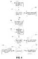
- FIG. 5is a flow chart illustrating the process of the mobile station of FIG. 3 wirelessly bridging to a landline station, in accordance with an exemplary embodiment of the present invention.
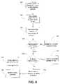
- FIG. 6is a flow chart illustrating the process of a landline station wirelessly bridging to the mobile station of FIG. 3 , in accordance with an exemplary embodiment of the present invention.
- the present inventionin its preferred embodiments, provides a “home zone” within which a mobile station may wirelessly bridge with a landline station, independently of both the wireless telecommunications network and the landline telecommunications network. In this way, the mobile station and the landline station may communicate without using the resources of the wireless and landline networks.
- the mobile stationmay add the landline station as a third party to a call, or the landline station may add the mobile station as a third party to a call, without using additional network resources.
- the “home zone”is defined by the wireless coverage area (which may be on the order of 100 meters) of a transceiver that is communicatively coupled to the landline telecommunications network.
- the transceivermay be a cordless base unit, and the landline station may be a cordless handset of the cordless base unit.
- the mobile stationwhile engaged in a call via a wireless telecommunications network, may wirelessly transmit a bridging signal to the transceiver, in order to include the landline station in the call independently of the landline telecommunications network. While the landline station is engaged in a call via the landline telecommunications network, the transceiver may wirelessly transmit a bridging signal to the mobile station, in order to include the mobile station in the call independently of the wireless telecommunications network.
- FIG. 1is a simplified block diagram of an exemplary telecommunications system 10 in which exemplary embodiments of the present invention may be employed.
- System 10includes a wireless telecommunications network, exemplified by a mobile switching center (MSC) 12 and a base transceiver station (BTS) 14 .
- MSC 12may be connected to the public switched telephone network (PSTN) 16 .
- PSTNpublic switched telephone network
- BTS 14may be connected to MSC 12 , in many cases via a base station controller (BSC) and/or other networks or systems.
- BSCbase station controller
- BTS 14provides a wireless coverage area, within which BTS 14 may communicate with one or more mobile stations, such as mobile station 18 , over an air interface.
- Mobile station 18may be a wireless telephone, a wirelessly equipped personal digital assistant (PDA), or other wireless device.
- the wireless communication between BTS 14 and mobile station 18may occur in cellular or PCS frequency band, and it may occur in a digital format, such as CDMA, TDMA, GSM, or 802.11x, or in an analog format, such as AMPS.
- mobile station 18is able to use the wireless telecommunications network, comprising MSC 12 and BTS 14 , to send and receive calls.
- PSTN 16is also connected to a landline telecommunications network, which may include one or more service switching points (SSPs), such as SSP 20 .
- SSP 20may be connected to a plurality of landline stations, which may be located in customers' premises, such as homes or businesses.
- the customer's premisesincludes a cordless base unit (CBU) 22 and a wireline telephone 24 connected to SSP 20 , via a telephone line 25 .
- CBU 22may communicate with one or more cordless handsets, such as cordless handset 26 .
- cordless handset 26 and wireline telephone 24are landline stations on telephone line 25 and may use the landline telecommunications network (exemplified by SSP 20 ), to send and receive calls.
- CBU 22includes an antenna 28 that provides a cordless-wireless coverage area, within which CBU 22 can communicate with cordless handset 26 over an air interface.
- CBU 22may use a cordless telephone frequency band, such as the 2.4 GHz cordless telephone frequency band, for cordless-wireless communications with handset 26 .
- CBU 22may use some other frequency band, which may or may not be a cordless telephone frequency band.
- the cordless-wireless communications between CBU 22 and handset 26may be encrypted.
- the cordless-wireless communicationsmay use a digital spread spectrum (DSS) technology, such as frequency-hopping.
- DSSdigital spread spectrum
- CBU 22may be able to communicate with a plurality of cordless handsets by using distinct cordless-wireless channels for each handset.
- CBU 22may have access to eight cordless-wireless channels and, thus, be able to communicate with eight cordless handsets.
- the cordless-wireless channelsmay be defined, for example, by different frequencies, different time slots, and/or different spreading codes.
- CBU 22may also use one of its available cordless-wireless channels to communicate with mobile station 18 over an air interface. Moreover, CBU 22 may be able to selectively provide two different types of communication pathways for mobile station 18 . In particular, CBU 22 may provide a first communication pathway to communicatively couple mobile station 18 and/or cordless handset 26 to telephone line 25 . CBU 22 may also be able to provide a second communication pathway to communicatively couple mobile station 18 with cordless handset 26 (via a wireless communication link), independently of the landline telecommunications network. In this way, CBU 22 may wirelessly bridge mobile station 18 with cordless handset 26 without involving the landline network. Moreover, as described in more detail below, this wireless bridging may occur while mobile station 18 is engaged in a call via the wireless telecommunications network and/or while cordless handset 26 is engaged in a call via the landline telecommunications network.
- FIG. 2illustrates an exemplary CBU 22 in more detail.
- CBU 22is connected to telephone line 25 via a telephone line interface 30 .
- Antenna 28may be connected to a transmit system 32 and a receive system 34 .
- CBU 22may also include an audio block 36 , which may include one or more speakers, microphones, codes, and/or other audio components.
- a multiplexer (MUX) 38may be connected to telephone line interface 30 , transmit system 32 , receive system 34 , and audio block 36 , so as to selectively interconnect these components.
- MUX 38may use time domain multiplexing and/or other types of multiplexing.
- MUX 38may connect transmit system 32 and receive system 34 to telephone line interface 30 .
- CBU 22may provide a communication pathway to communicatively couple mobile station 18 and/or cordless handset 26 with telephone 25 .
- telephone line interface 30may receive signals over telephone line 25 and send them to transmit system 32 , via MUX 38 .
- Transmit system 32then transmits the signals through antenna 28 to mobile station 18 and/or cordless handset 26 , using one or more cordless-wireless channels.
- antenna 28may receive signals over an air interface from mobile station 18 and/or cordless handset 26 , and receive system 34 sends the signals to telephone line interface 30 , via MUX 38 .
- Telephone line interface 30then transmits the signals over telephone line 25 .
- MUX 38may connect transmit system 32 to receive system 34 , so as to provide a communication pathway to communicatively couple mobile station 18 with cordless handset 26 .
- the communications between CBU 22 and mobile station 18may occur over an air interface using a first cordless-wireless channel (or channels), and the communications between CBU 22 and cordless handset 26 may occur over an air interface using a second cordless-wireless channel (or channels).
- mobile station 18may transmit signals to CBU 22 using the first cordless-wireless channel(s).
- Receive system 34receives the signals from mobile station 18 , via antenna 28 .
- MUX 38interconnects receive system 34 and transmit system 32 .
- transmit system 32receives the signals from receive system 34 and transmits them through antenna 28 to cordless handset 26 , using the second cordless-wireless channel(s).
- cordless handset 26may transmit signals using the second cordless-wireless channel(s).
- receive system 34receives the signals from cordless handset 26
- transmit system 32transmits the signals to mobile station 18 , using the first cordless-wireless channels.
- MUX 38may connect transmit system 32 , receive system 34 , and telephone line interface 30 so as to effectively join the two communication pathways. In this way, mobile station 18 and cordless handset 26 may both participate in a call over telephone line 25 , as described in more detail below.
- MUX 38may be controlled by a controller 40 .
- Controller 40may control CBU 22 in accordance with software programmed in CBU 22 .
- controller 40may include a processor that executes machine language instructions stored in data storage to control MUX 38 .
- Controller 40may control MUX 38 in accordance with instructions from a user.
- CBU 22may include a user interface 42 coupled to controller 38 .
- User interface 42may include a keypad, other buttons or controls, a touch screen, a voice recognition system, and/or other user input devices with which a user may enter instructions.
- User interface 42may also include a display or other devices to convey information to the user.
- Controller 40may receive instructions that a user has input by means of user interface 42 .
- controller 40may receive user instructions transmitted to CBU 22 over an air interface, such as from cordless handset 26 . Controller 40 may then control MUX 38 or other aspects of the operation of CBU 22 in response to the user instructions.
- a usermay be able to use user interface 42 and audio block 36 so as to use CBU 22 itself, i.e., without using cordless handset 26 , to send and receive calls via telephone line 25 .
- CBU 22may be able to act as a landline station, even without a cordless handset, such as cordless handset 26 .
- CBU 22may lack the functionality to send and receive calls.
- a usermay also be able to control CBU 22 to control its wireless communications with mobile station 18 .
- user interface 42may include a “mobile alert” button that, when pressed, causes CBU 22 to alert mobile station 18 by wirelessly transmitting a bridging signal.
- user interface 42may include a keypad or other input device with which the user may enter instructions that cause CBU 22 to transmit the bridging signal to mobile station 18 .
- a usermay be able to use a keypad 44 or other user interface on cordless handset 26 to cause CBU 22 to alert mobile station 18 .
- FIG. 3illustrates an exemplary mobile station 18 in more detail.
- mobile station 18may use separate antennas and separate transmit/receive systems for communicating with BTS 14 and communicating with CBU 22 .
- mobile station 18may include a first transmit/receive system 50 connected to a first antenna 52 , for communicating with BTS 14 , and a second transmit/receive system 54 connected to a second antenna 56 , for communicating with CBU 22 .
- antenna 52is an external antenna and antenna 56 is an internal antenna, but other configurations may be used.
- An audio block 58which may include one or more speakers, microphones, codecs, and other audio components, may be selectively connected to transmit/receive system 50 , transmit/receive system 54 , or both, via a multiplexer (MUX) 60 .
- MUX 60may be controlled by a controller 62 .
- Controller 62may control MUX 60 in accordance with software programmed in mobile station 18 .
- controller 62may include a processor that executes machine language instructions stored in data storage to control MUX 60 .
- Controller 62may control MUX 60 in accordance with user instructions entered by a user interface 64 .
- User interface 64may include a keypad with a plurality of keys with which the user may input alphanumeric characters and other symbols, such as “*” and “#”.
- the keypadmay also include one or more function keys, such as “SEND” and “END”.
- the usermay control aspects of the operation of mobile station 18 , such as the connections of MUX 60 , by entering appropriate keypad sequences.
- user interface 64may include a touch screen, voice recognition system, or other user input devices with which the user may enter instructions to control mobile station 18 .
- User interface 64may also a display or other devices for conveying information to the user.
- cordless base unit 22is used to wirelessly bridge mobile station 18 with a landline station (e.g, to cordless handset 26 ), more generally, a transceiver may be used for the wireless bridging.
- the transceivermay provide a first communication pathway for communicatively coupling the landline telecommunications network (exemplified by SSP 20 ) to one or more landline stations.
- the landline stationsmay, for example, include cordless handsets, wired extensions, and/or other telephony devices.
- a landline stationmay be integrated into the transceiver.
- the transceivermay provide a second communication pathway for communicatively coupling mobile station 18 to one or more landline stations, independently of the landline network.
- the transceivermay use an antenna to communicate with mobile station 18 , and the transceiver may use the same or a different antenna to communicate with cordless handsets.
- the frequency band that the transceiver uses to communicate with mobile station 18may be one that is used for cordless telephones, other frequency bands could be used.
- FIGS. 4 through 6show examples of wireless bridging between mobile station 18 and CBU 22 , using telecommunications system 10 , as shown in FIG. 1 .
- mobile station 18is able to originate a call through the landline telecommunications network by wirelessly bridging with CBU 22 , as summarized in FIG. 4 .
- the processmay begin when the user of mobile station 18 dials digits to originate a call, such as by using a keypad of user interface 64 , as indicated by step 100 .
- the usermay then have the option of routing the call through either the wireless telecommunications network (exemplified by BTS 14 and MSC 12 ) or the landline telecommunications network (exemplified by SSP 20 ) by wirelessly bridging to CBU 22 .
- the wireless telecommunications networkexemplified by BTS 14 and MSC 12
- the landline telecommunications networkexemplified by SSP 20
- whether the call is routed through the wireless network or through the landline networkmay depend on whether the user presses the “SEND” key, as indicated by step 102 . If the user presses the “SEND” key, then mobile station 18 may use antenna 52 to transmit to BTS 14 and, thereby, route the call through the wireless network, as indicated by step 104 .
- the usermay have the option of causing mobile station 18 to route the call through the landline network instead, by entering a predetermined instruction, such as by using a keypad of user interface 64 to enter “*77” (or other predetermined keypad sequence), as indicated by step 106 .
- mobile station 18may use antenna 54 to wirelessly transmit a bridging signal, as indicated by step 108 .
- Whether mobile station 18 is able to wirelessly bridge to CBU 22 in this way,may depend on whether mobile station 18 is within the “home zone,” as indicated by step 110 .
- the “home zone”may be defined by the wireless coverage area provided by antenna 28 of CBU 22 .
- mobile station 18may instead route the call through the wireless network, as indicated by step 112 .
- mobile station 18may include an antenna strength indicator to indicate the proximity of mobile station 18 to CBU 22 .
- the antenna strength indicatormay be an icon displayed on a display of user interface 64 . If mobile station 18 is out of range, then mobile station 18 may instead originate the call through the wireless network automatically, or mobile station 18 may provide the user with one or more alternative options.
- Whether mobile station 18 is able to wirelessly bridge to CBU 22may also depend on whether CBU 22 is busy, as indicated by step 114 .
- CBU 22may be busy because the telephone line to SSP 20 is being used by either cordless handset 26 or wireline telephone 24 .
- CBU 22may be able to complete the wireless bridge with mobile station 18 , even though cordless handset 26 or wireline telephone 24 is engaged in a call.
- mobile station 18may instead route the call through the wireless network, as indicated by step 116 . Mobile station 18 may do this automatically, or mobile station 18 may provide the user with one or more alternative options. In addition, if CBU 22 is busy, mobile station 18 may, but need not, provide a “busy” indication to the user.
- mobile station 18may successfully complete the wireless bridge with CBU 22 and may originate the call through the landline network (exemplified by SSP 20 ) via CBU 22 , as indicated by step 118 . At that point, mobile station 18 may act like any other cordless extension in communication with CBU 22 . Thus, other extensions connected to the telephone line to SSP 20 , such as cordless handset 26 and wireline telephone 24 , may join in on the call.
- mobile station 18may also be able to use a second line to originate or receive a call via the wireless network.
- the mobile station usermay be able to join the two calls together within mobile station 18 , by entering a predetermined instruction, such as “*88” or some other keypad sequence. In this way, mobile station 18 may be able to engage in three-way calling without using additional resources of the wireless network, e.g., an additional wireless channel.
- mobile station 18is able to wirelessly bridge with a landline station, such as cordless handset 26 , in order to include the landline station in a call carried by the wireless telecommunications network, as summarized in FIG. 5 .
- the processmay begin with mobile station 18 engaged in a call via the wireless network (exemplified by BTS 14 and MSC 12 ), as indicated by step 200 .
- Mobile station 18may have either originated or received the call.
- Mobile station 18may use antenna 52 for communicating with BTS 14 for this call.
- the mobile station usermay enter a predetermined instruction, such as by using a keypad of user interface 64 to enter “*77” or other keypad sequence, as indicated as step 202 .
- mobile station 18wirelessly transmits a bridging signal, as indicated by step 204 .
- Mobile station 18may use a different antenna for transmitting the bridging signal than for communicating with BTS 14 .
- mobile station 18may use antenna 56 to transmit the bridging signal.
- Whether mobile station 18 is able to complete the wirelessly bridgemay depend on whether mobile station 18 is within the “home zone,” as indicated by step 206 . If mobile station 18 is not within the “home zone,” then mobile station 18 may be unable to complete the wireless bridge, as indicated by step 208 .
- mobile station 18may include an antenna strength indicator to indicate the proximity to CBU 22 , i.e., whether mobile station 18 is within the “home zone” provided by CBU 22 . However, mobile station 18 may provide alternative indications to the user that mobile station 18 is out of range.
- Whether mobile station 18 is able to complete the wireless bridgemay also depend on whether CBU 22 is busy, as indicated by step 210 . If CBU 22 is busy, then mobile station 18 may be unable to complete the wireless bridge, as indicated by step 212 . If CBU 22 is busy, then mobile station 18 may, but need not, provide a “busy” indication to the user.
- CBU 22alerts the landline station, as indicated by step 214 .
- the alertmay involve “ringing” cordless handset 26 and/or CBU 22 , particularly if CBU 22 can itself function as a landline station. More generally, the alert may involve a visible indication, such as a flashing light or displaying text or graphics, a tactile indication, such as a vibration, an audible indication, such as ringing, beeping, or buzzing, or some other type of user-discernible indication from cordless handset 26 and/or CBU 22 . Moreover, this alert occurs independently of the landline communications network (exemplified by SSP 20 ). In particular, the alert is generated or initiated by CBU 22 , rather than by SSP 20 .
- a landline station usermay then answer the alert, as indicated by step 216 , such as by causing CBU 22 and/or cordless handset 26 to go off-hook.
- a wireless communication linkis established between mobile station 18 and the landline station, e.g., cordless handset 26 .
- this wireless communication linkis established independently of the landline network (exemplified by SSP 20 ).
- CBU 22communicatively couples mobile station 18 with the landline station without involving the landline network.
- the mobile station usermay carry on the conversations on the two lines independently, e.g., by alternating between the two lines. However, the mobile station user may also be able to conference the two lines together, such as by entering “*88” on a keypad of user interface 64 , as indicated by step 218 . In response to the “*88” or other keypad instruction, mobile station 18 conferences the two lines together, e.g., by using MUX 60 . In this way, the landline station is joined to the call being carried by the wireless network, as indicated by step 220 .
- mobile station 18may first establish the wireless communication link with the landline station and then either originate or receive a call via the wireless telecommunications network.
- mobile station 18may include a the landline station as a third party to a call without using the resources of the landline network and without using additional resources (e.g., an additional wireless channel) of the wireless network.
- a landline stationsuch as CBU 22 and/or cordless handset 26 , is able to wirelessly bridge with mobile station 18 , in order to include mobile station 18 in a call carried by the landline telecommunications network, as summarized in FIG. 6 .
- the processmay begin with the landline station engaged in a call via the landline network (exemplified by SSP 20 ), as indicated by step 300 .
- the landline station usermay enter a predetermined instruction, such as by using user interface 42 , as indicated by step 302 .
- the usermay press a “mobile alert” button of user interface 42 , or the user may use a keypad of user interface 42 to enter a keypad sequence, such as *77 or *78.
- the usermay enter different instructions to contact different types of mobile stations or to contact a selected one of a plurality of mobile stations within the “home zone.”
- the usermay enter *77 to contact a mobile station from one manufacturer and may enter *78 to contact a mobile station from another manufacturer.
- the usermay also be able to enter the predetermined instruction remotely, such as by using keypad 44 or other user interface of cordless handset 26 .
- CBU 22wirelessly transmits a bridging signal, as indicated by step 304 .
- CBU 22is able to complete the wireless bridge to mobile station 18 may depend on whether mobile station 18 is within the “home zone,” as indicated by step 306 . If mobile station 18 is not within the “home zone,” then CBU 22 may be unable to complete the wireless bridge with mobile station 18 , as indicated by step 308 . CBU 22 and/or cordless handset 26 may, but need not, provide an “out of range” indication to the landline station user. Whether CBU 22 can wirelessly bridge to mobile station 18 may also depend on whether mobile station 18 is busy, as indicated by step 310 .
- mobile station 18may not be busy even if already engaged in a call, e.g., a call carried by the wireless telecommunications network. If mobile station 18 is busy, then CBU 22 may be unable to complete the wireless bridge, as indicated by step 312 . CBU 22 and/or cordless handset 26 may, but need not, provide a “busy” indicate to the landline station user.
- mobile station 18may provide a user-discernible indication that mobile station 18 is being alerted, as indicated by step 314 .
- the user-discernible indicationmay involve a visible indication, such as a flashing light or displaying text or graphics, a tactile indication, such as a vibration, an audible indication, such as ringing, beeping, or buzzing, or some other type of user-discernible indication.
- the mobile station usermay then answer, as indicated by step 316 .
- a wireless communication linkis established between mobile station 18 and the landline station, and mobile station 18 may act like a cordless extension of CBU 22 .
- mobile stationis joined to the call being carried by the landline telecommunications network, as indicated by step 318 .
- mobile station 18may be able to conference the two calls together within mobile station 18 .
- mobile station 18may be able to originate or receive a call via the wireless network and then join that call to the call being carried by the landline network.
- CBU 22may first establish the wireless communication link with mobile station 18 and then either originate or receive a call via the landline telecommunications network.
- this process of establishing the establishing the wireless communication link between mobile station 18 and the landline stationoccurs independently of the landline and wireless networks.
- the landline stationmay add mobile station 18 as a third party to a call without using the resources of the wireless network and without using additional resources (e.g., an additional telephone line) of the landline network.
Landscapes
- Engineering & Computer Science (AREA)
- Computer Networks & Wireless Communication (AREA)
- Signal Processing (AREA)
- Mobile Radio Communication Systems (AREA)
Abstract
Description
Claims (5)
Priority Applications (2)
| Application Number | Priority Date | Filing Date | Title |
|---|---|---|---|
| US10/316,689US7299060B1 (en) | 2002-12-10 | 2002-12-10 | Method and system for wireless bridging |
| US11/848,835US7907917B1 (en) | 2002-12-10 | 2007-08-31 | Method and system for wireless bridging |
Applications Claiming Priority (1)
| Application Number | Priority Date | Filing Date | Title |
|---|---|---|---|
| US10/316,689US7299060B1 (en) | 2002-12-10 | 2002-12-10 | Method and system for wireless bridging |
Related Child Applications (1)
| Application Number | Title | Priority Date | Filing Date |
|---|---|---|---|
| US11/848,835ContinuationUS7907917B1 (en) | 2002-12-10 | 2007-08-31 | Method and system for wireless bridging |
Publications (1)
| Publication Number | Publication Date |
|---|---|
| US7299060B1true US7299060B1 (en) | 2007-11-20 |
Family
ID=38691027
Family Applications (2)
| Application Number | Title | Priority Date | Filing Date |
|---|---|---|---|
| US10/316,689Expired - Fee RelatedUS7299060B1 (en) | 2002-12-10 | 2002-12-10 | Method and system for wireless bridging |
| US11/848,835Expired - Fee RelatedUS7907917B1 (en) | 2002-12-10 | 2007-08-31 | Method and system for wireless bridging |
Family Applications After (1)
| Application Number | Title | Priority Date | Filing Date |
|---|---|---|---|
| US11/848,835Expired - Fee RelatedUS7907917B1 (en) | 2002-12-10 | 2007-08-31 | Method and system for wireless bridging |
Country Status (1)
| Country | Link |
|---|---|
| US (2) | US7299060B1 (en) |
Cited By (3)
| Publication number | Priority date | Publication date | Assignee | Title |
|---|---|---|---|---|
| US20060205433A1 (en)* | 2005-03-08 | 2006-09-14 | Samsung Electronics Co., Ltd. | Method and apparatus for receiving signals using diversity in wireless network |
| US7907917B1 (en) | 2002-12-10 | 2011-03-15 | Sprint Spectrum L.P. | Method and system for wireless bridging |
| US10536990B1 (en)* | 2009-02-03 | 2020-01-14 | Dominic M. Kotab | Telephone base station for combining mobile and terrestrial telephone service |
Citations (47)
| Publication number | Priority date | Publication date | Assignee | Title |
|---|---|---|---|---|
| US4989230A (en) | 1988-09-23 | 1991-01-29 | Motorola, Inc. | Cellular cordless telephone |
| US5127042A (en) | 1988-09-23 | 1992-06-30 | Motorola, Inc. | Cellular cordless telephone |
| US5247567A (en) | 1991-05-20 | 1993-09-21 | Pioneer Electronic Corporation | Portable-to-portable talk system for cordless telephone |
| US5327578A (en)* | 1990-09-10 | 1994-07-05 | Motorola, Inc. | Radio telephone system supporting automatic busy and out-of-range indications |
| US5442680A (en) | 1992-06-23 | 1995-08-15 | Motorola, Inc. | Dual system cellular cordless radiotelephone apparatus with sub-data channel timing monitor |
| US5528666A (en) | 1994-07-01 | 1996-06-18 | Motorola, Inc. | Personal phone expansion system |
| US5550895A (en) | 1993-12-02 | 1996-08-27 | Lucent Technologies Inc. | Bimodal portable telephone |
| US5594782A (en) | 1994-02-24 | 1997-01-14 | Gte Mobile Communications Service Corporation | Multiple mode personal wireless communications system |
| US5619553A (en) | 1993-06-02 | 1997-04-08 | Vtech Communications, Ltd. | Method of conducting an intercom communication between two cordless telephone handsets |
| US5675629A (en)* | 1995-09-08 | 1997-10-07 | At&T | Cordless cellular system base station |
| US5699409A (en) | 1994-08-26 | 1997-12-16 | Nec Corporation | Cordless telephone system for providing set-up communications between subsidiary units through a master unit |
| US5758290A (en) | 1994-07-05 | 1998-05-26 | Lucent Technologies Inc. | Cordless telephone arranged for operating with multiple portable units in a frequency hopping system |
| US5771453A (en) | 1993-11-04 | 1998-06-23 | Ericsson Inc. | Multiple user base stations and methods for radio personal communications systems |
| US5774805A (en)* | 1994-02-24 | 1998-06-30 | Gte Mobile Communications Service Corporation | Multi-mode communication network with handset-selected channel assignments |
| US5911120A (en) | 1995-09-08 | 1999-06-08 | At&T Wireless Services | Wireless communication system having mobile stations establish a communication link through the base station without using a landline or regional cellular network and without a call in progress |
| US5999823A (en) | 1996-07-18 | 1999-12-07 | Matsushita Electric Industrial Co., Ltd. | Cellular cordless telephone |
| US6044268A (en) | 1997-07-16 | 2000-03-28 | Telefonaktiebolaget Lm Ericsson Ab | System and method for providing intercom and multiple voice channels in a private telephone system |
| US6078822A (en) | 1997-06-19 | 2000-06-20 | Nec Corporation | Cordless telephone system and its independent base station and mobile station |
| US6085109A (en) | 1992-04-30 | 2000-07-04 | Matsushita Electric Industrial Co., Ltd. | Wireless telephone equipment operating as a cordless and cellular telephone |
| US6091758A (en) | 1997-10-01 | 2000-07-18 | Lucent Technologies Inc. | Cordless telephone arranged for operating with multiple portable units in a frequency hopping system |
| US6122508A (en)* | 1995-12-16 | 2000-09-19 | Alcatel | Mobile radio system with wireline subscriber lines |
| US6138011A (en)* | 1999-10-15 | 2000-10-24 | Motorola, Inc. | Method and apparatus for providing dispatch service to an existing telephone network |
| US6141562A (en)* | 1994-12-30 | 2000-10-31 | Telefonaktiebolaget Lm Ericsson | System and method relating to cordless communications |
| US6141547A (en) | 1997-07-17 | 2000-10-31 | Alcatel | Radiotelecommunications system having a mobile terminal that operates both in cellular mode and in cordless mode |
| US6154650A (en) | 1998-06-03 | 2000-11-28 | Ericsson, Inc. | System and method for delivering a call for a mobile station using either a wireless network or a wireline network |
| US6167278A (en) | 1986-10-22 | 2000-12-26 | Nilssen; Ole K. | Combination cordless-cellular telephone system |
| US6205338B1 (en) | 1997-08-14 | 2001-03-20 | Samsung Electronics Co., Ltd. | Intercommunication method between portable units in TDMA cordless telephone system |
| US6226515B1 (en) | 1995-05-31 | 2001-05-01 | Siemens Aktiengesellschaft | Cellular cordless telecommunications system |
| US6253088B1 (en) | 1997-11-24 | 2001-06-26 | Uniden America Corporation | Personal base station for integrated cellular and cordless communication system |
| US6289089B1 (en) | 1996-09-16 | 2001-09-11 | Siemens Schweiz Ag | Key telephone system with cordless terminals |
| US20010046215A1 (en) | 2000-05-24 | 2001-11-29 | Kim Ki-Chul | Wire/wireless unified in-building communication method and system |
| US6351653B1 (en)* | 2000-06-15 | 2002-02-26 | Motorola, Inc. | Cellular telephone with simultaneous radio and cellular communications |
| US6381230B1 (en) | 1998-07-28 | 2002-04-30 | Qualcomm Incorporated | Method and system for providing personal base station communications |
| US6389299B1 (en) | 1998-12-30 | 2002-05-14 | Samsung Electronics, Co., Ltd. | System and method for interfacing a cordless handset with a main telephone set in a radio switching system |
| US20020094848A1 (en)* | 1997-10-10 | 2002-07-18 | Umesh Amin | Method and system for providing power to a communications device |
| US6434394B1 (en) | 1998-10-02 | 2002-08-13 | Lucent Technologies Inc. | Multiple handset cordless telephone including a ring signal/call routing module |
| US20020115471A1 (en)* | 2001-02-19 | 2002-08-22 | Alcatel | Method for handling calls received at a wireless mobile terminal comprising a short-range interface, corresponding wireless mobile terminal and computer program |
| US20020115455A1 (en)* | 2001-02-22 | 2002-08-22 | Siemens Information And Communication Products, Llc | Extended range cordless telephone system and method |
| US6484027B1 (en) | 1998-06-15 | 2002-11-19 | Sbc Technology Resources, Inc. | Enhanced wireless handset, including direct handset-to-handset communication mode |
| US20020198020A1 (en) | 2001-06-26 | 2002-12-26 | Mooney Philip D. | Automatic handoff for wireless piconet multimode cell phone |
| US20030039242A1 (en) | 2001-07-06 | 2003-02-27 | General Instrument Corporation | Methods, apparatus,and systems for accessing mobile and voice over IP telephone networks with a mobile handset |
| US20030045294A1 (en) | 2001-09-04 | 2003-03-06 | Alcatel | Mobile station with two communication interfaces |
| US20030139180A1 (en)* | 2002-01-24 | 2003-07-24 | Mcintosh Chris P. | Private cellular network with a public network interface and a wireless local area network extension |
| US20030157929A1 (en)* | 2002-01-04 | 2003-08-21 | Holger Janssen | Apparatus for conducting a conference call between a wireless line and a land line using customer premise equipment |
| US6829478B1 (en)* | 1999-11-19 | 2004-12-07 | Pamela G. Layton | Information management network for automated delivery of alarm notifications and other information |
| US6871064B1 (en)* | 1997-11-04 | 2005-03-22 | Bellsouth Intellectual Property Corporation | Outgoing call handling system and method |
| US20050130646A1 (en)* | 2001-12-26 | 2005-06-16 | Bellsouth Intellectual Property Corporation | Auto sensing home base station for mobile telephone with remote answering capabilities |
Family Cites Families (5)
| Publication number | Priority date | Publication date | Assignee | Title |
|---|---|---|---|---|
| US6122502A (en)* | 1997-12-23 | 2000-09-19 | Lucent Technologies Inc. | Roaming cordless telephone |
| US6788953B1 (en)* | 2000-06-05 | 2004-09-07 | Uniden America Corporation | Wireless local loop communication system using SLIC module |
| JP2002199455A (en)* | 2000-12-27 | 2002-07-12 | Matsushita Electric Ind Co Ltd | Cordless telephone equipment |
| US7233808B2 (en)* | 2001-09-05 | 2007-06-19 | Agere Systems Inc. | Smart BLUETOOTH interface gateway to mate a non-BLUETOOTH wireless device with a BLUETOOTH headset |
| US7299060B1 (en) | 2002-12-10 | 2007-11-20 | Sprint Spectrum L.P. | Method and system for wireless bridging |
- 2002
- 2002-12-10USUS10/316,689patent/US7299060B1/ennot_activeExpired - Fee Related
- 2007
- 2007-08-31USUS11/848,835patent/US7907917B1/ennot_activeExpired - Fee Related
Patent Citations (50)
| Publication number | Priority date | Publication date | Assignee | Title |
|---|---|---|---|---|
| US6167278A (en) | 1986-10-22 | 2000-12-26 | Nilssen; Ole K. | Combination cordless-cellular telephone system |
| US5127042A (en) | 1988-09-23 | 1992-06-30 | Motorola, Inc. | Cellular cordless telephone |
| US4989230A (en) | 1988-09-23 | 1991-01-29 | Motorola, Inc. | Cellular cordless telephone |
| US5327578A (en)* | 1990-09-10 | 1994-07-05 | Motorola, Inc. | Radio telephone system supporting automatic busy and out-of-range indications |
| US5247567A (en) | 1991-05-20 | 1993-09-21 | Pioneer Electronic Corporation | Portable-to-portable talk system for cordless telephone |
| US6085109A (en) | 1992-04-30 | 2000-07-04 | Matsushita Electric Industrial Co., Ltd. | Wireless telephone equipment operating as a cordless and cellular telephone |
| US5442680A (en) | 1992-06-23 | 1995-08-15 | Motorola, Inc. | Dual system cellular cordless radiotelephone apparatus with sub-data channel timing monitor |
| US5619553A (en) | 1993-06-02 | 1997-04-08 | Vtech Communications, Ltd. | Method of conducting an intercom communication between two cordless telephone handsets |
| US5771453A (en) | 1993-11-04 | 1998-06-23 | Ericsson Inc. | Multiple user base stations and methods for radio personal communications systems |
| US5550895A (en) | 1993-12-02 | 1996-08-27 | Lucent Technologies Inc. | Bimodal portable telephone |
| US5594782A (en) | 1994-02-24 | 1997-01-14 | Gte Mobile Communications Service Corporation | Multiple mode personal wireless communications system |
| US6243593B1 (en)* | 1994-02-24 | 2001-06-05 | Gte Wireless Service Corporation | Module for providing wireless call communication services through wire-connected telephone equipment |
| US5774805A (en)* | 1994-02-24 | 1998-06-30 | Gte Mobile Communications Service Corporation | Multi-mode communication network with handset-selected channel assignments |
| US5528666A (en) | 1994-07-01 | 1996-06-18 | Motorola, Inc. | Personal phone expansion system |
| US5809417A (en) | 1994-07-05 | 1998-09-15 | Lucent Technologies Inc. | Cordless telephone arranged for operating with multiple portable units in a frequency hopping system |
| US5758290A (en) | 1994-07-05 | 1998-05-26 | Lucent Technologies Inc. | Cordless telephone arranged for operating with multiple portable units in a frequency hopping system |
| US5699409A (en) | 1994-08-26 | 1997-12-16 | Nec Corporation | Cordless telephone system for providing set-up communications between subsidiary units through a master unit |
| US6141562A (en)* | 1994-12-30 | 2000-10-31 | Telefonaktiebolaget Lm Ericsson | System and method relating to cordless communications |
| US6226515B1 (en) | 1995-05-31 | 2001-05-01 | Siemens Aktiengesellschaft | Cellular cordless telecommunications system |
| US5911120A (en) | 1995-09-08 | 1999-06-08 | At&T Wireless Services | Wireless communication system having mobile stations establish a communication link through the base station without using a landline or regional cellular network and without a call in progress |
| US6611692B2 (en)* | 1995-09-08 | 2003-08-26 | At&T Wireless Services, Inc. | Cordless cellular system |
| US5675629A (en)* | 1995-09-08 | 1997-10-07 | At&T | Cordless cellular system base station |
| US6122508A (en)* | 1995-12-16 | 2000-09-19 | Alcatel | Mobile radio system with wireline subscriber lines |
| US5999823A (en) | 1996-07-18 | 1999-12-07 | Matsushita Electric Industrial Co., Ltd. | Cellular cordless telephone |
| US6289089B1 (en) | 1996-09-16 | 2001-09-11 | Siemens Schweiz Ag | Key telephone system with cordless terminals |
| US6078822A (en) | 1997-06-19 | 2000-06-20 | Nec Corporation | Cordless telephone system and its independent base station and mobile station |
| US6044268A (en) | 1997-07-16 | 2000-03-28 | Telefonaktiebolaget Lm Ericsson Ab | System and method for providing intercom and multiple voice channels in a private telephone system |
| US6141547A (en) | 1997-07-17 | 2000-10-31 | Alcatel | Radiotelecommunications system having a mobile terminal that operates both in cellular mode and in cordless mode |
| US6205338B1 (en) | 1997-08-14 | 2001-03-20 | Samsung Electronics Co., Ltd. | Intercommunication method between portable units in TDMA cordless telephone system |
| US6091758A (en) | 1997-10-01 | 2000-07-18 | Lucent Technologies Inc. | Cordless telephone arranged for operating with multiple portable units in a frequency hopping system |
| US20020094848A1 (en)* | 1997-10-10 | 2002-07-18 | Umesh Amin | Method and system for providing power to a communications device |
| US6871064B1 (en)* | 1997-11-04 | 2005-03-22 | Bellsouth Intellectual Property Corporation | Outgoing call handling system and method |
| US6253088B1 (en) | 1997-11-24 | 2001-06-26 | Uniden America Corporation | Personal base station for integrated cellular and cordless communication system |
| US6154650A (en) | 1998-06-03 | 2000-11-28 | Ericsson, Inc. | System and method for delivering a call for a mobile station using either a wireless network or a wireline network |
| US6484027B1 (en) | 1998-06-15 | 2002-11-19 | Sbc Technology Resources, Inc. | Enhanced wireless handset, including direct handset-to-handset communication mode |
| US6381230B1 (en) | 1998-07-28 | 2002-04-30 | Qualcomm Incorporated | Method and system for providing personal base station communications |
| US6434394B1 (en) | 1998-10-02 | 2002-08-13 | Lucent Technologies Inc. | Multiple handset cordless telephone including a ring signal/call routing module |
| US6389299B1 (en) | 1998-12-30 | 2002-05-14 | Samsung Electronics, Co., Ltd. | System and method for interfacing a cordless handset with a main telephone set in a radio switching system |
| US6138011A (en)* | 1999-10-15 | 2000-10-24 | Motorola, Inc. | Method and apparatus for providing dispatch service to an existing telephone network |
| US6829478B1 (en)* | 1999-11-19 | 2004-12-07 | Pamela G. Layton | Information management network for automated delivery of alarm notifications and other information |
| US20010046215A1 (en) | 2000-05-24 | 2001-11-29 | Kim Ki-Chul | Wire/wireless unified in-building communication method and system |
| US6351653B1 (en)* | 2000-06-15 | 2002-02-26 | Motorola, Inc. | Cellular telephone with simultaneous radio and cellular communications |
| US20020115471A1 (en)* | 2001-02-19 | 2002-08-22 | Alcatel | Method for handling calls received at a wireless mobile terminal comprising a short-range interface, corresponding wireless mobile terminal and computer program |
| US20020115455A1 (en)* | 2001-02-22 | 2002-08-22 | Siemens Information And Communication Products, Llc | Extended range cordless telephone system and method |
| US20020198020A1 (en) | 2001-06-26 | 2002-12-26 | Mooney Philip D. | Automatic handoff for wireless piconet multimode cell phone |
| US20030039242A1 (en) | 2001-07-06 | 2003-02-27 | General Instrument Corporation | Methods, apparatus,and systems for accessing mobile and voice over IP telephone networks with a mobile handset |
| US20030045294A1 (en) | 2001-09-04 | 2003-03-06 | Alcatel | Mobile station with two communication interfaces |
| US20050130646A1 (en)* | 2001-12-26 | 2005-06-16 | Bellsouth Intellectual Property Corporation | Auto sensing home base station for mobile telephone with remote answering capabilities |
| US20030157929A1 (en)* | 2002-01-04 | 2003-08-21 | Holger Janssen | Apparatus for conducting a conference call between a wireless line and a land line using customer premise equipment |
| US20030139180A1 (en)* | 2002-01-24 | 2003-07-24 | Mcintosh Chris P. | Private cellular network with a public network interface and a wireless local area network extension |
Cited By (7)
| Publication number | Priority date | Publication date | Assignee | Title |
|---|---|---|---|---|
| US7907917B1 (en) | 2002-12-10 | 2011-03-15 | Sprint Spectrum L.P. | Method and system for wireless bridging |
| US20060205433A1 (en)* | 2005-03-08 | 2006-09-14 | Samsung Electronics Co., Ltd. | Method and apparatus for receiving signals using diversity in wireless network |
| US10536990B1 (en)* | 2009-02-03 | 2020-01-14 | Dominic M. Kotab | Telephone base station for combining mobile and terrestrial telephone service |
| US10555137B2 (en)* | 2009-02-03 | 2020-02-04 | Dominic M. Kotab | Telephone base station for combining mobile and terrestrial telephone service |
| US10681507B2 (en)* | 2009-02-03 | 2020-06-09 | Dominic M. Kotab | Telephone base station for combining mobile and terrestrial telephone service |
| US10785612B2 (en)* | 2009-02-03 | 2020-09-22 | Dominic M. Kotab | Telephone base station for combining mobile and terrestrial telephone service |
| US10887732B2 (en)* | 2009-02-03 | 2021-01-05 | Dominic M. Kotab | Telephone base station for combining mobile and VOIP telephone service |
Also Published As
| Publication number | Publication date |
|---|---|
| US7907917B1 (en) | 2011-03-15 |
Similar Documents
| Publication | Publication Date | Title |
|---|---|---|
| US6304642B1 (en) | Peer-to-peer data transfer using pre-existing caller ID CLASS FSK signaling infrastructure | |
| US5533096A (en) | Send-all-calls feature for a wireless handset | |
| EP0954156A2 (en) | Conference call | |
| KR20010101793A (en) | Group call for a wireless mobile communication device using bluetooth | |
| US7184783B1 (en) | Method and system for transmitting character messages in mobile communication terminal during conversation by telephone | |
| US7907917B1 (en) | Method and system for wireless bridging | |
| JP3041244B2 (en) | Message communication method and device | |
| JP3529283B2 (en) | Line selection device | |
| KR100430308B1 (en) | Selected Station Call Method Using Caller ID In Wireless Telephone | |
| KR100797921B1 (en) | Caller ID display control method of communication system | |
| US20060089175A1 (en) | Call switchover in wireless headset | |
| KR20050049151A (en) | Method for notifying urgent call in mobile phone | |
| JPH06165244A (en) | Mobile radio telephone system | |
| JPH03213022A (en) | Wireless telephone equipment and wireless communication systems | |
| US6487239B1 (en) | Method and apparatus for message communication | |
| JP3562430B2 (en) | Mobile communication system and method of notifying incoming call to mobile phone | |
| JP2002218059A (en) | Portable telephone | |
| JP2868458B2 (en) | Communication method between mobile stations | |
| KR20020057682A (en) | Method of building call in mobile communication terminal | |
| JP2001008259A (en) | Method for controlling call-back communication and system thereof | |
| KR100248102B1 (en) | Apparatus and method for using ct-2 line and co line selecting in pbx | |
| KR100222658B1 (en) | Method for transceiving phone number using forward control channel | |
| KR100600386B1 (en) | Caller voice output method of mobile communication terminal | |
| JPH0691585B2 (en) | Extension calling device of a private electronic exchange using wireless | |
| KR20030008902A (en) | Method for two-direction communication between mobile terminal and fixed terminal |
Legal Events
| Date | Code | Title | Description |
|---|---|---|---|
| AS | Assignment | Owner name:SPRINT SPECTRUM L.P., KANSAS Free format text:ASSIGNMENT OF ASSIGNORS INTEREST;ASSIGNORS:DRONAMRAJU, SRIRAMA KRISHAN;DAHDOUH, KHALIL;REEL/FRAME:013584/0125 Effective date:20021205 | |
| STCF | Information on status: patent grant | Free format text:PATENTED CASE | |
| FPAY | Fee payment | Year of fee payment:4 | |
| FPAY | Fee payment | Year of fee payment:8 | |
| AS | Assignment | Owner name:DEUTSCHE BANK TRUST COMPANY AMERICAS, NEW YORK Free format text:GRANT OF FIRST PRIORITY AND JUNIOR PRIORITY SECURITY INTEREST IN PATENT RIGHTS;ASSIGNOR:SPRINT COMMUNICATIONS COMPANY L.P.;REEL/FRAME:041895/0210 Effective date:20170203 | |
| FEPP | Fee payment procedure | Free format text:MAINTENANCE FEE REMINDER MAILED (ORIGINAL EVENT CODE: REM.); ENTITY STATUS OF PATENT OWNER: LARGE ENTITY | |
| LAPS | Lapse for failure to pay maintenance fees | Free format text:PATENT EXPIRED FOR FAILURE TO PAY MAINTENANCE FEES (ORIGINAL EVENT CODE: EXP.); ENTITY STATUS OF PATENT OWNER: LARGE ENTITY | |
| STCH | Information on status: patent discontinuation | Free format text:PATENT EXPIRED DUE TO NONPAYMENT OF MAINTENANCE FEES UNDER 37 CFR 1.362 | |
| FP | Lapsed due to failure to pay maintenance fee | Effective date:20191120 | |
| AS | Assignment | Owner name:SPRINT COMMUNICATIONS COMPANY L.P., KANSAS Free format text:TERMINATION AND RELEASE OF FIRST PRIORITY AND JUNIOR PRIORITY SECURITY INTEREST IN PATENT RIGHTS;ASSIGNOR:DEUTSCHE BANK TRUST COMPANY AMERICAS;REEL/FRAME:052969/0475 Effective date:20200401 |