US7298854B2 - Apparatus, methods and articles of manufacture for noise reduction in electromagnetic signal processing - Google Patents
Apparatus, methods and articles of manufacture for noise reduction in electromagnetic signal processingDownload PDFInfo
- Publication number
- US7298854B2 US7298854B2US10/309,518US30951802AUS7298854B2US 7298854 B2US7298854 B2US 7298854B2US 30951802 AUS30951802 AUS 30951802AUS 7298854 B2US7298854 B2US 7298854B2
- Authority
- US
- United States
- Prior art keywords
- wave
- transfer function
- filter
- applying
- amplitude
- Prior art date
- Legal status (The legal status is an assumption and is not a legal conclusion. Google has not performed a legal analysis and makes no representation as to the accuracy of the status listed.)
- Expired - Fee Related, expires
Links
- 238000000034methodMethods0.000titleclaimsabstractdescription17
- 238000004519manufacturing processMethods0.000titleabstractdescription5
- 230000009467reductionEffects0.000titledescription5
- 238000012545processingMethods0.000titledescription3
- 238000012546transferMethods0.000claimsabstractdescription22
- 230000004044responseEffects0.000claimsdescription6
- 230000004048modificationEffects0.000description6
- 238000012986modificationMethods0.000description6
- 230000003321amplificationEffects0.000description5
- 238000003199nucleic acid amplification methodMethods0.000description5
- 230000001105regulatory effectEffects0.000description5
- 238000001914filtrationMethods0.000description4
- 238000004458analytical methodMethods0.000description3
- 229910000577Silicon-germaniumInorganic materials0.000description2
- 230000008859changeEffects0.000description2
- 239000002131composite materialSubstances0.000description2
- 230000001419dependent effectEffects0.000description2
- 238000005070samplingMethods0.000description2
- JBRZTFJDHDCESZ-UHFFFAOYSA-NAsGaChemical compound[As]#[Ga]JBRZTFJDHDCESZ-UHFFFAOYSA-N0.000description1
- XUIMIQQOPSSXEZ-UHFFFAOYSA-NSiliconChemical compound[Si]XUIMIQQOPSSXEZ-UHFFFAOYSA-N0.000description1
- LEVVHYCKPQWKOP-UHFFFAOYSA-N[Si].[Ge]Chemical compound[Si].[Ge]LEVVHYCKPQWKOP-UHFFFAOYSA-N0.000description1
- 230000004913activationEffects0.000description1
- 230000033228biological regulationEffects0.000description1
- 230000005540biological transmissionEffects0.000description1
- 230000001413cellular effectEffects0.000description1
- 238000004891communicationMethods0.000description1
- 230000003247decreasing effectEffects0.000description1
- 238000009795derivationMethods0.000description1
- 238000010586diagramMethods0.000description1
- 230000000694effectsEffects0.000description1
- 230000005284excitationEffects0.000description1
- 230000003278mimic effectEffects0.000description1
- 239000000203mixtureSubstances0.000description1
- 238000013139quantizationMethods0.000description1
- 230000036632reaction speedEffects0.000description1
- 230000011218segmentationEffects0.000description1
- 239000004065semiconductorSubstances0.000description1
- 229910052710siliconInorganic materials0.000description1
- 239000010703siliconSubstances0.000description1
- 238000001228spectrumMethods0.000description1
- 239000000758substrateSubstances0.000description1
- 230000001360synchronised effectEffects0.000description1
- 230000007704transitionEffects0.000description1
Images


Classifications
- H—ELECTRICITY
- H03—ELECTRONIC CIRCUITRY
- H03H—IMPEDANCE NETWORKS, e.g. RESONANT CIRCUITS; RESONATORS
- H03H17/00—Networks using digital techniques
- H03H17/02—Frequency selective networks
- H03H17/0202—Two or more dimensional filters; Filters for complex signals
- H—ELECTRICITY
- H03—ELECTRONIC CIRCUITRY
- H03F—AMPLIFIERS
- H03F2200/00—Indexing scheme relating to amplifiers
- H03F2200/504—Indexing scheme relating to amplifiers the supply voltage or current being continuously controlled by a controlling signal, e.g. the controlling signal of a transistor implemented as variable resistor in a supply path for, an IC-block showed amplifier
Definitions
- the inventionrelates generally to electromagnetic signal processing, and more particularly to the reduction of noise in electromagnetic signal processing, and more particularly to the reduction of noise in segmented amplifiers used in RF transmitters.
- Electromagnetic waveshave, until fairly recently, been modified using analog techniques. That is, there had been no attempt to isolate discrete wave characteristics such as current, voltage and the like and modify those characteristics in order to modify the wave itself. Recently, wave modification techniques have become digitized, so that characteristics of the wave can be isolated and modified directly in order to achieve a desired result. Digitization has become desirable because it usually provides more speed and precision in wave modification while drawing less power than previous methods.
- digitization of wave characteristicshas led to improvements in filtering techniques.
- digitizing wave characteristicsit is possible to quickly and accurately create and/or modify, (e.g. implement, emphasize, isolate and filter) frequencies and other wave characteristics.
- Embodiments of the present inventioninclude apparatus, methods and articles of manufacture for modifying electromagnetic waves by reducing noise in those waves.
- the preferred method embodimentscomprise a method of applying a transfer function wherein a desired output wave parameter is determined, an amplitude characteristic and a phase characteristic of an input wave are isolated, the transfer function is derived from the desired output wave parameter and the transfer function is applied to the amplitude characteristic of the wave. Following application of the transfer function, the amplitude characteristic and said phase characteristic may be combined so as to generate an output wave.
- FIG. 1shows a preferred embodiment
- FIG. 2shows a preferred embodiment
- FIG. 3shows various results of a preferred embodiment.
- FIG. 4shows various results of a preferred embodiment.
- FIG. 1shows a preferred embodiment.
- An input wave ais provided to a Digital Signal Processor 10 .
- Digital Signal Processor 10comprises an Analog to Digital Converter 11 , which digitizes the wave, for example, by the use of rectangular coordinates or I,Q data.
- Rectangular to Polar Converter 12then receives the I,Q data and translates it into polar coordinates.
- a digitized representation of a wavemay be provided to a rectangular to polar converter if desired.
- the digitized representationmay be generated in any of a number of ways as is known in the art.
- this embodimentis described as used in connection with a digitized wave and I,Q and polar data, those of ordinary skill in the art will appreciate that other embodiments are not limited thereto and may use any digital or analog wave form, or combination thereof.
- Rectangular to Polar Converter 12outputs a digitized wave in polar coordinates, which takes the form R, P(sin) and P(cos) for example.
- the R coordinaterepresents the amplitude characteristic of the wave.
- the P(sin) and P(cos) coordinatesrepresent the phase characteristic of the wave.
- characteristicrefers to electromagnetic wave characteristics, such as frequency, voltage, amplitude (including magnitude and envelope), phase, current, wave shape, or pulse. Other embodiments may derive one or more wave characteristics from the input wave as desired.
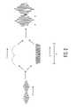
- FIG. 2a schematic diagram of a wave that has been translated according to the embodiment of FIG. 1 is shown.
- Input wave ahas been translated into magnitude component m comprising magnitude characteristics of the input wave over period t 1 and phase component p comprising phase characteristics on a carrier wave over the same period.
- Output wave bis shown after amplification by a preferred embodiment.
- the time period in this and other embodimentsis as desired.
- embodimentsmay derive magnitude and phase characteristics of a wave using various sampling rates in order to maximize resolution of the wave, maximize speed of operation, etc. These sampling rates may be dynamically determined as well in various embodiments so that they change during operation.
- the division of an input waveis synchronized, in order to maximize accuracy of output and minimize any distortion.
- amplitude and phase characteristicsare then transmitted through separate paths.
- the amplitude characteristics of the input waveare converted, via converter 13 , along path a m , into digital pulses comprising a digital word quantized into bits B 0 to B n ⁇ 1 , with a Most Significant Bit (“MSB”) to Least Significant Bit (“LSB”).
- MSBMost Significant Bit
- LSBLeast Significant Bit
- the digital wordmay be of varying lengths in various embodiments. In general, the longer the word the greater the accuracy of reproduction of the input wave.
- the digital wordprovides control for attenuation and/or amplification, in manner to be described further below.
- a differently composed digital wordmay be used, as well as other types of derivation and/or provision of amplitude or other wave characteristics.
- Converter 13then splits the bits, each of which are a time-domain square waveform onto separate paths 0 to N ⁇ 1.
- Each bitenters low-pass filter bank 30 which is comprised of filters F 0 to F n ⁇ 1 .
- the impulse response of filters F 0 to Fn ⁇ 1is at h(t) 0 to h(t) N ⁇ 1 respectively, which is further described below.
- control component lines 21 a - gare shown leading away from the converter 13 .
- the number of these control component linesdepends, in the preferred embodiments, upon the resolution of the word. In this preferred embodiment, the word has a seven bit resolution.
- the control component linesare consolidated into a single path a m leading into control components 22 a - g . However, in the embodiment, and as further described below, the control component lines are not consolidated and instead feed into the control components individually.
- the phase characteristictravels along path a p .
- the phase characteristicis first modulated onto a wave by way of Digital to Analog Converter 18 and Synthesizer 20 (which is a Voltage Controlled Oscillator in an especially preferred embodiment.)
- Synthesizer 20provides an output wave, which is comprised of the phase information.
- This output wavehas a constant envelope, i.e., it has no amplitude variations, yet it has phase characteristics of the original input wave, and passes to driver 24 , and in turn driver lines a p 1 -a p 7 .
- the wave, which has been split among the driver lines,is then fed into current sources 25 a - 25 g , and will serve to potentially drive the current sources 25 a - 25 g as is further described below.
- other sources of other wave characteristicsi.e., besides the phase characteristic, may be used.
- transistorsmay be used as current sources 25 a - 25 g .
- one or more transistors segmented appropriatelymay be used as current sources 25 a - 25 g .
- the current sources 25 a - 25 gmust not be driven into saturation. Otherwise, the current sources will cease to act as current sources and instead act as voltage sources, which will interfere with the desired current combining of the sources.
- Path a mterminates in control components 22 a - g .
- theseare switching transistors, and are preferably current sources, although, as further described below, in other embodiments, other sources of other wave characteristics may be used, as well as other regulation schemes.
- Control components 22 a - gare switched by bits of the digital word output from the amplitude component and so regulated by the digital word output from the amplitude component. If a bit is “1” or “high,” the corresponding control component is switched on, and so current flows from that control component to appropriate current source 25 a - g along bias control lines 23 a - g .
- the length of the digital wordmay vary, and so the number of bits, control components, control component lines, driver lines, bias control lines, current sources, etc. may vary accordingly in various embodiments. Moreover, there does not have to be a one to one correspondence among digital word resolution, components, lines and current sources in various embodiments.
- Current sources 25 a - greceive current from a control component if the control component is on, and thus each current source is regulated according to that component.
- an appropriate control componentprovides bias current to the current sources, as is described further below, and so the control component may be referred to as a bias control circuit, and a number of them as a bias network.
- itmay be desired to statically or dynamically allocate one or more bias control circuits to one or more current sources using a switching network if desired.
- each current sourceserves as a potential current source, and is capable of generating a current, which is output to current source lines 26 a - g respectively.
- Each current sourcemay or may not act as a current source, and so may or may not generate a current, because it is regulated via the appropriate digital word value regulating a control component. Activation of any current source, and generation of current from that current source, is dependant upon the value of the appropriate bit from the digital representation of the amplitude component regulating the appropriate control component.
- the current sourcesare not an amplifier or amplifiers in the preferred embodiments, rather the plurality of current sources function as an amplifier, as is described herein. Indeed, amplification and/or attenuation may be considered in the preferred embodiments as functions of those embodiments, and so may an amplifier and/or attenuator be considered to be an electrical component or system that amplifies and/or attenuates.
- the combined currenti.e. the sum of any current output from current sources 25 a - g , is the current sources output.
- the embodimentmay act as an attenuator and/or amplifier. No further circuitry or components are necessary between the current sources to combine current from each current source and so provide a useful output current. Therefore, the combined current, which is output on line 27 , and shown as b, may be used as desired, e.g., as an amplifier, as an attenuator, to drive a load, etc.
- the output signal s out from transistor 25can be expressed as:
- s(t)representing the input signal
- the input signalcan be represented by:
- embodiments of the inventionmay be entirely comprised of hardware, software or may be a combination of software and hardware.
- the embodiments or various componentsmay also be provided on a semiconductor device where desired, such as an integrated circuit or an application-specific integrated circuit composition; some examples include silicon (Si), silicon germanium (SiGe) or gallium arsenide (GaAs) substrates.
- Various embodimentsmay provide desired levels of precision. For example, the length of the digital word may be longer or shorter in various embodiments, thus providing a more or less precise digitization of the wave. As other examples, the number of control components, transistor segments, etc. may all be varied as desired. Additionally, in various embodiments, non-linear components may be utilized if desired, although in these embodiments, it is preferred to utilize non-linear components in an amplitude path after a signal has been digitized.
- inventionsmay include apparatus and/or methods and/or articles of manufacture that are specialized for particular input signals, carrier waves and output signals e.g. embodiments may be used in various RF, microprocessor, microcontroller and/or computer devices, e.g. cell phones, such as CDMA, CDMA2000, W-CDMA, GSM, TDMA, as well as other wired and wireless devices, e.g.
Landscapes
- Physics & Mathematics (AREA)
- Engineering & Computer Science (AREA)
- Computer Hardware Design (AREA)
- Mathematical Physics (AREA)
- Amplifiers (AREA)
Abstract
Description
Sout(t)=As(t)
provides a different value or weight to the output signal as had been described above, the output signal may also be represented by
Wi=2i−1
- with s1(t) being the LSB and SN(t), being the MSB.
- and, if equations (c) and (f) are combined, as:
- then, it also possible to apply equation (g) to equation (h), and obtain
Claims (9)
Priority Applications (5)
| Application Number | Priority Date | Filing Date | Title |
|---|---|---|---|
| US10/309,518US7298854B2 (en) | 2002-12-04 | 2002-12-04 | Apparatus, methods and articles of manufacture for noise reduction in electromagnetic signal processing |
| EP03774725AEP1566030A2 (en) | 2002-10-08 | 2003-10-07 | Apparatus, methods and articles of manufacture for noise reduction in electromagnetic signal processing |
| PCT/US2003/032023WO2004034664A2 (en) | 2002-10-08 | 2003-10-07 | Apparatus, methods and articles of manufacture for noise reduction in electromagnetic signal processing |
| JP2004543601AJP2006502671A (en) | 2002-10-08 | 2003-10-07 | Input signal electromagnetic processing device |
| AU2003282535AAU2003282535A1 (en) | 2002-10-08 | 2003-10-07 | Apparatus, methods and articles of manufacture for noise reduction in electromagnetic signal processing |
Applications Claiming Priority (1)
| Application Number | Priority Date | Filing Date | Title |
|---|---|---|---|
| US10/309,518US7298854B2 (en) | 2002-12-04 | 2002-12-04 | Apparatus, methods and articles of manufacture for noise reduction in electromagnetic signal processing |
Publications (2)
| Publication Number | Publication Date |
|---|---|
| US20040109572A1 US20040109572A1 (en) | 2004-06-10 |
| US7298854B2true US7298854B2 (en) | 2007-11-20 |
Family
ID=32467880
Family Applications (1)
| Application Number | Title | Priority Date | Filing Date |
|---|---|---|---|
| US10/309,518Expired - Fee RelatedUS7298854B2 (en) | 2002-10-08 | 2002-12-04 | Apparatus, methods and articles of manufacture for noise reduction in electromagnetic signal processing |
Country Status (1)
| Country | Link |
|---|---|
| US (1) | US7298854B2 (en) |
Cited By (1)
| Publication number | Priority date | Publication date | Assignee | Title |
|---|---|---|---|---|
| US10135409B1 (en)* | 2016-02-02 | 2018-11-20 | Marvell International Ltd. | High-efficiency RF digital power amplifier with joint duty-cycle/amplitude modulation |
Families Citing this family (2)
| Publication number | Priority date | Publication date | Assignee | Title |
|---|---|---|---|---|
| US7307570B2 (en) | 2005-07-20 | 2007-12-11 | M/A-Com, Inc. | Method and apparatus to emulate a filter |
| US7436339B2 (en) | 2005-07-20 | 2008-10-14 | M/A-Com, Inc. | Method and apparatus to emulate a filter using digital elements |
Citations (87)
| Publication number | Priority date | Publication date | Assignee | Title |
|---|---|---|---|---|
| GB1383286A (en) | 1972-08-23 | 1974-02-12 | Ibm | Digital transversal filter |
| US3900823A (en)* | 1973-03-28 | 1975-08-19 | Nathan O Sokal | Amplifying and processing apparatus for modulated carrier signals |
| US3978422A (en) | 1975-02-28 | 1976-08-31 | Alpha Engineering Corporation | Broadband automatic gain control amplifier |
| US4276620A (en) | 1978-10-27 | 1981-06-30 | Geosource Inc. | Method and apparatus for obtaining a composite field response _to a variable source array using weighting coefficients |
| US4580111A (en) | 1981-12-24 | 1986-04-01 | Harris Corporation | Amplitude modulation using digitally selected carrier amplifiers |
| US4586000A (en) | 1982-02-10 | 1986-04-29 | Ford Aerospace & Communications Corporation | Transformerless current balanced amplifier |
| US4646359A (en) | 1984-05-10 | 1987-02-24 | Bbc Brown, Boveri & Company Limited | Method and apparatus for controlling the carrier of an amplitude-modulated transmitter |
| US4888808A (en)* | 1987-03-23 | 1989-12-19 | Matsushita Electric Industrial Co., Ltd. | Digital equalizer apparatus enabling separate phase and amplitude characteristic modification |
| US5051942A (en)* | 1987-12-18 | 1991-09-24 | Matsushita Electric Industrial Co., Ltd. | Method and apparatus for calculating filter factors |
| US5095507A (en)* | 1990-07-24 | 1992-03-10 | Lowe Danny D | Method and apparatus for generating incoherent multiples of a monaural input signal for sound image placement |
| US5142240A (en)* | 1989-12-27 | 1992-08-25 | Mitsubishi Denki Kabushiki Kaisha | Amplifier circuit with correction of amplitude and phase distortions |
| US5278997A (en) | 1990-12-17 | 1994-01-11 | Motorola, Inc. | Dynamically biased amplifier |
| US5311143A (en) | 1992-07-02 | 1994-05-10 | Motorola, Inc. | RF amplifier bias control method and apparatus |
| US5377274A (en)* | 1989-12-28 | 1994-12-27 | Meyer Sound Laboratories Incorporated | Correction circuit and method for improving the transient behavior of a two-way loudspeaker system |
| US5410280A (en) | 1993-05-28 | 1995-04-25 | Thomson-Csf | Process and device for amplitude modulation of a radiofrequency signal |
| US5524286A (en) | 1993-12-14 | 1996-06-04 | Alcatel Italia S.P.A. | Baseband predistortion system for the adaptive linearization of power amplifiers |
| US5598436A (en) | 1993-06-29 | 1997-01-28 | U.S. Philips Corporation | Digital transmission system with predistortion |
| US5642002A (en) | 1993-10-29 | 1997-06-24 | Alpha Technologies | Apparatus and methods for generating uninterruptible AC power signals |
| US5774017A (en) | 1996-06-03 | 1998-06-30 | Anadigics, Inc. | Multiple-band amplifier |
| US5818298A (en) | 1994-01-11 | 1998-10-06 | Ericsson Inc. | Linear amplifying apparatus using coupled non-linear amplifiers |
| US5880633A (en) | 1997-05-08 | 1999-03-09 | Motorola, Inc. | High efficiency power amplifier |
| US5886913A (en) | 1997-05-29 | 1999-03-23 | Alcatel Alsthom Compagnie Generale D'electricite | Method of synthesizing a finite impulse response digital filter and filter obtained by this method |
| US5892431A (en) | 1997-05-20 | 1999-04-06 | Alpha Technologies, Inc. | Power multiplexer for broadband communications systems |
| US5905760A (en) | 1996-03-22 | 1999-05-18 | Matra Communication | Method of correcting nonlinearities of an amplifier, and radio transmitter employing a method of this type |
| US5930128A (en) | 1998-04-02 | 1999-07-27 | Ericsson Inc. | Power waveform synthesis using bilateral devices |
| US5939951A (en) | 1995-05-25 | 1999-08-17 | Btg International Limited | Methods and apparatus for modulating, demodulating and amplifying |
| US5942946A (en) | 1997-10-10 | 1999-08-24 | Industrial Technology Research Institute | RF power amplifier with high efficiency and a wide range of gain control |
| US5952895A (en) | 1998-02-23 | 1999-09-14 | Tropian, Inc. | Direct digital synthesis of precise, stable angle modulated RF signal |
| US6043712A (en) | 1998-07-17 | 2000-03-28 | Motorola, Inc. | Linear power amplifier |
| US6043707A (en) | 1999-01-07 | 2000-03-28 | Motorola, Inc. | Method and apparatus for operating a radio-frequency power amplifier as a variable-class linear amplifier |
| US6075413A (en) | 1997-12-10 | 2000-06-13 | Sony Corporation | Amplifier circuit and control signal generator |
| US6078628A (en) | 1998-03-13 | 2000-06-20 | Conexant Systems, Inc. | Non-linear constant envelope modulator and transmit architecture |
| US6094101A (en) | 1999-03-17 | 2000-07-25 | Tropian, Inc. | Direct digital frequency synthesis enabling spur elimination |
| US6097252A (en) | 1997-06-02 | 2000-08-01 | Motorola, Inc. | Method and apparatus for high efficiency power amplification |
| US6101224A (en) | 1998-10-07 | 2000-08-08 | Telefonaktiebolaget Lm Ericsson | Method and apparatus for generating a linearly modulated signal using polar modulation |
| US6112071A (en) | 1998-02-23 | 2000-08-29 | Tropian, Inc. | Quadrature-free RF receiver for directly receiving angle modulated signal |
| US6125266A (en) | 1997-12-31 | 2000-09-26 | Nokia Mobile Phones Limited | Dual band architectures for mobile stations having transmitter linearization feedback |
| US6133788A (en) | 1998-04-02 | 2000-10-17 | Ericsson Inc. | Hybrid Chireix/Doherty amplifiers and methods |
| US6140882A (en) | 1998-11-23 | 2000-10-31 | Tropian, Inc. | Phase lock loop enabling smooth loop bandwidth switching |
| US6140875A (en) | 1997-08-12 | 2000-10-31 | U.S. Philips Corporation | Device for amplifying digital signals |
| US6147553A (en) | 1998-03-06 | 2000-11-14 | Fujant, Inc. | Amplification using amplitude reconstruction of amplitude and/or angle modulated carrier |
| US6157681A (en) | 1998-04-06 | 2000-12-05 | Motorola, Inc. | Transmitter system and method of operation therefor |
| WO2001010013A1 (en) | 1999-07-29 | 2001-02-08 | Tropian, Inc. | High-efficiency modulating rf amplifier |
| US6191653B1 (en) | 1998-11-18 | 2001-02-20 | Ericsson Inc. | Circuit and method for linearizing amplitude modulation in a power amplifier |
| US6198347B1 (en) | 1999-07-29 | 2001-03-06 | Tropian, Inc. | Driving circuits for switch mode RF power amplifiers |
| US6201452B1 (en) | 1998-12-10 | 2001-03-13 | Ericsson Inc. | Systems and methods for converting a stream of complex numbers into a modulated radio power signal |
| US6215355B1 (en) | 1999-10-13 | 2001-04-10 | Tropian, Inc. | Constant impedance for switchable amplifier with power control |
| US6219394B1 (en) | 1997-10-08 | 2001-04-17 | Tropian, Inc. | Digital frequency sampling and discrimination |
| US6236284B1 (en) | 2000-04-07 | 2001-05-22 | Harris Corporation | RF power amplifier system having distributed modulation encoding |
| US6242975B1 (en) | 1999-05-25 | 2001-06-05 | Conexant Systems, Inc. | Envelope peak and trough limiting to improve amplifier efficiency and distortion characteristics |
| US6246286B1 (en) | 1999-10-26 | 2001-06-12 | Telefonaktiebolaget Lm Ericsson | Adaptive linearization of power amplifiers |
| US6255906B1 (en) | 1999-09-30 | 2001-07-03 | Conexant Systems, Inc. | Power amplifier operated as an envelope digital to analog converter with digital pre-distortion |
| US6259901B1 (en) | 1998-07-03 | 2001-07-10 | Mobile Communications Tokyo Inc. | Radio-frequency power amplifier of mobile communication equipment |
| US6269135B1 (en) | 1998-01-14 | 2001-07-31 | Tropian, Inc. | Digital phase discriminations based on frequency sampling |
| US6285251B1 (en) | 1998-04-02 | 2001-09-04 | Ericsson Inc. | Amplification systems and methods using fixed and modulated power supply voltages and buck-boost control |
| US6288916B1 (en) | 1999-10-15 | 2001-09-11 | Alpha Technologies, Inc. | Multiple output uninterruptible alternating current power supplies for communications system |
| US6294957B1 (en) | 2000-01-21 | 2001-09-25 | Harris Corporation | RF power amplifier having synchronous RF drive |
| US6311046B1 (en) | 1998-04-02 | 2001-10-30 | Ericsson Inc. | Linear amplification systems and methods using more than two constant length vectors |
| US6317608B1 (en) | 1998-05-22 | 2001-11-13 | Telefonaktiebolaget Lm Ericsson | Power amplifier matching in dual band mobile phone |
| US6321072B1 (en) | 1998-08-31 | 2001-11-20 | Conexant Systems, Inc. | Distortion control feedback loop utilizing a non-linear transfer function generator to compensate for non-linearities in a transmitter circuit |
| US6323731B1 (en) | 2000-10-06 | 2001-11-27 | Tropion, Inc. Corp. | Variable bias control for switch mode RF amplifier |
| EP1170915A1 (en) | 1999-03-31 | 2002-01-09 | Kabushiki Kaisha Toshiba | Signal modulation circuit and method for signal modulation |
| US6356155B1 (en) | 2001-04-11 | 2002-03-12 | Tropian Inc. | Multi-band amplifier having multi-tap RF choke |
| US6366177B1 (en) | 2000-02-02 | 2002-04-02 | Tropian Inc. | High-efficiency power modulators |
| US6369657B2 (en) | 1999-12-20 | 2002-04-09 | Rf Micro Devices, Inc. | Bias network for high efficiency RF linear power amplifier |
| US6377784B2 (en) | 1999-02-09 | 2002-04-23 | Tropian, Inc. | High-efficiency modulation RF amplifier |
| US6380802B1 (en) | 2000-12-29 | 2002-04-30 | Ericsson Inc. | Transmitter using input modulation for envelope restoration scheme for linear high-efficiency power amplification |
| US6404823B1 (en) | 1998-07-01 | 2002-06-11 | Conexant Systems, Inc. | Envelope feedforward technique with power control for efficient linear RF power amplification |
| US6411655B1 (en) | 1998-12-18 | 2002-06-25 | Ericsson Inc. | Systems and methods for converting a stream of complex numbers into an amplitude and phase-modulated radio power signal |
| US20020098812A1 (en) | 2001-01-25 | 2002-07-25 | Essam Sourour | Amplifier phase change compensation |
| US6426678B1 (en) | 2001-01-18 | 2002-07-30 | Samsung Electronics Co., Ltd. | High power amplifier system having low power consumption and high dynamic range |
| US6426677B1 (en) | 2001-09-14 | 2002-07-30 | Intersil Americas Inc. | Linearization bias circuit for BJT amplifiers |
| US6430402B1 (en) | 1998-09-14 | 2002-08-06 | Conexant Systems, Inc. | Power amplifier saturation prevention method, apparatus, and communication system incorporating the same |
| US6445247B1 (en) | 2001-06-01 | 2002-09-03 | Qualcomm Incorporated | Self-controlled high efficiency power amplifier |
| US6449465B1 (en) | 1999-12-20 | 2002-09-10 | Motorola, Inc. | Method and apparatus for linear amplification of a radio frequency signal |
| US20020186783A1 (en) | 2001-06-07 | 2002-12-12 | Motorola, Inc | Amplifier predistortion system and method |
| US20020193085A1 (en) | 2001-06-15 | 2002-12-19 | Telefonaktiebolaget Lm Ericsson | Systems and methods for amplification of a communication signal |
| US6512417B2 (en)* | 2000-05-11 | 2003-01-28 | Nortel Networks Limited | Linear amplifier arrangement |
| US20030095608A1 (en) | 2001-11-16 | 2003-05-22 | Koninklijke Philips Electronics N.V. | Transmitter with transmitter chain phase adjustment on the basis of pre-stored phase information |
| US6621340B1 (en) | 2000-02-24 | 2003-09-16 | Fraunhofer-Gesellschaft zur Förderung der angewandten Forschung e.V. | System for reducing adjacent-channel interference by pre-linearization and pre-distortion |
| US20030215026A1 (en) | 2002-05-16 | 2003-11-20 | Hietala Alexander Wayne | AM to AM correction system for polar modulator |
| US20030215025A1 (en) | 2002-05-16 | 2003-11-20 | Hietala Alexander Wayne | AM to PM correction system for polar modulator |
| US20040021517A1 (en) | 2002-08-05 | 2004-02-05 | Spectrian Corporation | Power minimization, correlation-based closed loop for controlling predistorter and vector modulator feeding RF power amplifier |
| US20040047432A1 (en) | 2002-06-28 | 2004-03-11 | Nec Corporation | Nonlinear distortion compensating circuit |
| US6834084B2 (en) | 2002-05-06 | 2004-12-21 | Rf Micro Devices Inc | Direct digital polar modulator |
| US20050017801A1 (en) | 2003-07-23 | 2005-01-27 | Andrew Corporation | Elimination of peak clipping and improved efficiency for RF power amplifiers with a predistorter |
| US20050122164A1 (en) | 2003-12-05 | 2005-06-09 | Per-Olof Brandt | Single chip power amplifier and envelope modulator |
- 2002
- 2002-12-04USUS10/309,518patent/US7298854B2/ennot_activeExpired - Fee Related
Patent Citations (87)
| Publication number | Priority date | Publication date | Assignee | Title |
|---|---|---|---|---|
| GB1383286A (en) | 1972-08-23 | 1974-02-12 | Ibm | Digital transversal filter |
| US3900823A (en)* | 1973-03-28 | 1975-08-19 | Nathan O Sokal | Amplifying and processing apparatus for modulated carrier signals |
| US3978422A (en) | 1975-02-28 | 1976-08-31 | Alpha Engineering Corporation | Broadband automatic gain control amplifier |
| US4276620A (en) | 1978-10-27 | 1981-06-30 | Geosource Inc. | Method and apparatus for obtaining a composite field response _to a variable source array using weighting coefficients |
| US4580111A (en) | 1981-12-24 | 1986-04-01 | Harris Corporation | Amplitude modulation using digitally selected carrier amplifiers |
| US4586000A (en) | 1982-02-10 | 1986-04-29 | Ford Aerospace & Communications Corporation | Transformerless current balanced amplifier |
| US4646359A (en) | 1984-05-10 | 1987-02-24 | Bbc Brown, Boveri & Company Limited | Method and apparatus for controlling the carrier of an amplitude-modulated transmitter |
| US4888808A (en)* | 1987-03-23 | 1989-12-19 | Matsushita Electric Industrial Co., Ltd. | Digital equalizer apparatus enabling separate phase and amplitude characteristic modification |
| US5051942A (en)* | 1987-12-18 | 1991-09-24 | Matsushita Electric Industrial Co., Ltd. | Method and apparatus for calculating filter factors |
| US5142240A (en)* | 1989-12-27 | 1992-08-25 | Mitsubishi Denki Kabushiki Kaisha | Amplifier circuit with correction of amplitude and phase distortions |
| US5377274A (en)* | 1989-12-28 | 1994-12-27 | Meyer Sound Laboratories Incorporated | Correction circuit and method for improving the transient behavior of a two-way loudspeaker system |
| US5095507A (en)* | 1990-07-24 | 1992-03-10 | Lowe Danny D | Method and apparatus for generating incoherent multiples of a monaural input signal for sound image placement |
| US5278997A (en) | 1990-12-17 | 1994-01-11 | Motorola, Inc. | Dynamically biased amplifier |
| US5311143A (en) | 1992-07-02 | 1994-05-10 | Motorola, Inc. | RF amplifier bias control method and apparatus |
| US5410280A (en) | 1993-05-28 | 1995-04-25 | Thomson-Csf | Process and device for amplitude modulation of a radiofrequency signal |
| US5598436A (en) | 1993-06-29 | 1997-01-28 | U.S. Philips Corporation | Digital transmission system with predistortion |
| US5642002A (en) | 1993-10-29 | 1997-06-24 | Alpha Technologies | Apparatus and methods for generating uninterruptible AC power signals |
| US5524286A (en) | 1993-12-14 | 1996-06-04 | Alcatel Italia S.P.A. | Baseband predistortion system for the adaptive linearization of power amplifiers |
| US5818298A (en) | 1994-01-11 | 1998-10-06 | Ericsson Inc. | Linear amplifying apparatus using coupled non-linear amplifiers |
| US5939951A (en) | 1995-05-25 | 1999-08-17 | Btg International Limited | Methods and apparatus for modulating, demodulating and amplifying |
| US5905760A (en) | 1996-03-22 | 1999-05-18 | Matra Communication | Method of correcting nonlinearities of an amplifier, and radio transmitter employing a method of this type |
| US5774017A (en) | 1996-06-03 | 1998-06-30 | Anadigics, Inc. | Multiple-band amplifier |
| US5880633A (en) | 1997-05-08 | 1999-03-09 | Motorola, Inc. | High efficiency power amplifier |
| US5892431A (en) | 1997-05-20 | 1999-04-06 | Alpha Technologies, Inc. | Power multiplexer for broadband communications systems |
| US5886913A (en) | 1997-05-29 | 1999-03-23 | Alcatel Alsthom Compagnie Generale D'electricite | Method of synthesizing a finite impulse response digital filter and filter obtained by this method |
| US6097252A (en) | 1997-06-02 | 2000-08-01 | Motorola, Inc. | Method and apparatus for high efficiency power amplification |
| US6140875A (en) | 1997-08-12 | 2000-10-31 | U.S. Philips Corporation | Device for amplifying digital signals |
| US6219394B1 (en) | 1997-10-08 | 2001-04-17 | Tropian, Inc. | Digital frequency sampling and discrimination |
| US5942946A (en) | 1997-10-10 | 1999-08-24 | Industrial Technology Research Institute | RF power amplifier with high efficiency and a wide range of gain control |
| US6075413A (en) | 1997-12-10 | 2000-06-13 | Sony Corporation | Amplifier circuit and control signal generator |
| US6125266A (en) | 1997-12-31 | 2000-09-26 | Nokia Mobile Phones Limited | Dual band architectures for mobile stations having transmitter linearization feedback |
| US6269135B1 (en) | 1998-01-14 | 2001-07-31 | Tropian, Inc. | Digital phase discriminations based on frequency sampling |
| US5952895A (en) | 1998-02-23 | 1999-09-14 | Tropian, Inc. | Direct digital synthesis of precise, stable angle modulated RF signal |
| US6112071A (en) | 1998-02-23 | 2000-08-29 | Tropian, Inc. | Quadrature-free RF receiver for directly receiving angle modulated signal |
| US6147553A (en) | 1998-03-06 | 2000-11-14 | Fujant, Inc. | Amplification using amplitude reconstruction of amplitude and/or angle modulated carrier |
| US6078628A (en) | 1998-03-13 | 2000-06-20 | Conexant Systems, Inc. | Non-linear constant envelope modulator and transmit architecture |
| US5930128A (en) | 1998-04-02 | 1999-07-27 | Ericsson Inc. | Power waveform synthesis using bilateral devices |
| US6285251B1 (en) | 1998-04-02 | 2001-09-04 | Ericsson Inc. | Amplification systems and methods using fixed and modulated power supply voltages and buck-boost control |
| US6133788A (en) | 1998-04-02 | 2000-10-17 | Ericsson Inc. | Hybrid Chireix/Doherty amplifiers and methods |
| US6311046B1 (en) | 1998-04-02 | 2001-10-30 | Ericsson Inc. | Linear amplification systems and methods using more than two constant length vectors |
| US6157681A (en) | 1998-04-06 | 2000-12-05 | Motorola, Inc. | Transmitter system and method of operation therefor |
| US6317608B1 (en) | 1998-05-22 | 2001-11-13 | Telefonaktiebolaget Lm Ericsson | Power amplifier matching in dual band mobile phone |
| US6404823B1 (en) | 1998-07-01 | 2002-06-11 | Conexant Systems, Inc. | Envelope feedforward technique with power control for efficient linear RF power amplification |
| US6259901B1 (en) | 1998-07-03 | 2001-07-10 | Mobile Communications Tokyo Inc. | Radio-frequency power amplifier of mobile communication equipment |
| US6043712A (en) | 1998-07-17 | 2000-03-28 | Motorola, Inc. | Linear power amplifier |
| US6321072B1 (en) | 1998-08-31 | 2001-11-20 | Conexant Systems, Inc. | Distortion control feedback loop utilizing a non-linear transfer function generator to compensate for non-linearities in a transmitter circuit |
| US6430402B1 (en) | 1998-09-14 | 2002-08-06 | Conexant Systems, Inc. | Power amplifier saturation prevention method, apparatus, and communication system incorporating the same |
| US6101224A (en) | 1998-10-07 | 2000-08-08 | Telefonaktiebolaget Lm Ericsson | Method and apparatus for generating a linearly modulated signal using polar modulation |
| US6191653B1 (en) | 1998-11-18 | 2001-02-20 | Ericsson Inc. | Circuit and method for linearizing amplitude modulation in a power amplifier |
| US6140882A (en) | 1998-11-23 | 2000-10-31 | Tropian, Inc. | Phase lock loop enabling smooth loop bandwidth switching |
| US6201452B1 (en) | 1998-12-10 | 2001-03-13 | Ericsson Inc. | Systems and methods for converting a stream of complex numbers into a modulated radio power signal |
| US6411655B1 (en) | 1998-12-18 | 2002-06-25 | Ericsson Inc. | Systems and methods for converting a stream of complex numbers into an amplitude and phase-modulated radio power signal |
| US6043707A (en) | 1999-01-07 | 2000-03-28 | Motorola, Inc. | Method and apparatus for operating a radio-frequency power amplifier as a variable-class linear amplifier |
| US6377784B2 (en) | 1999-02-09 | 2002-04-23 | Tropian, Inc. | High-efficiency modulation RF amplifier |
| US6094101A (en) | 1999-03-17 | 2000-07-25 | Tropian, Inc. | Direct digital frequency synthesis enabling spur elimination |
| EP1170915A1 (en) | 1999-03-31 | 2002-01-09 | Kabushiki Kaisha Toshiba | Signal modulation circuit and method for signal modulation |
| US6242975B1 (en) | 1999-05-25 | 2001-06-05 | Conexant Systems, Inc. | Envelope peak and trough limiting to improve amplifier efficiency and distortion characteristics |
| WO2001010013A1 (en) | 1999-07-29 | 2001-02-08 | Tropian, Inc. | High-efficiency modulating rf amplifier |
| US6198347B1 (en) | 1999-07-29 | 2001-03-06 | Tropian, Inc. | Driving circuits for switch mode RF power amplifiers |
| US6255906B1 (en) | 1999-09-30 | 2001-07-03 | Conexant Systems, Inc. | Power amplifier operated as an envelope digital to analog converter with digital pre-distortion |
| US6215355B1 (en) | 1999-10-13 | 2001-04-10 | Tropian, Inc. | Constant impedance for switchable amplifier with power control |
| US6288916B1 (en) | 1999-10-15 | 2001-09-11 | Alpha Technologies, Inc. | Multiple output uninterruptible alternating current power supplies for communications system |
| US6246286B1 (en) | 1999-10-26 | 2001-06-12 | Telefonaktiebolaget Lm Ericsson | Adaptive linearization of power amplifiers |
| US6369657B2 (en) | 1999-12-20 | 2002-04-09 | Rf Micro Devices, Inc. | Bias network for high efficiency RF linear power amplifier |
| US6449465B1 (en) | 1999-12-20 | 2002-09-10 | Motorola, Inc. | Method and apparatus for linear amplification of a radio frequency signal |
| US6294957B1 (en) | 2000-01-21 | 2001-09-25 | Harris Corporation | RF power amplifier having synchronous RF drive |
| US6366177B1 (en) | 2000-02-02 | 2002-04-02 | Tropian Inc. | High-efficiency power modulators |
| US6621340B1 (en) | 2000-02-24 | 2003-09-16 | Fraunhofer-Gesellschaft zur Förderung der angewandten Forschung e.V. | System for reducing adjacent-channel interference by pre-linearization and pre-distortion |
| US6236284B1 (en) | 2000-04-07 | 2001-05-22 | Harris Corporation | RF power amplifier system having distributed modulation encoding |
| US6512417B2 (en)* | 2000-05-11 | 2003-01-28 | Nortel Networks Limited | Linear amplifier arrangement |
| US6323731B1 (en) | 2000-10-06 | 2001-11-27 | Tropion, Inc. Corp. | Variable bias control for switch mode RF amplifier |
| US6380802B1 (en) | 2000-12-29 | 2002-04-30 | Ericsson Inc. | Transmitter using input modulation for envelope restoration scheme for linear high-efficiency power amplification |
| US6426678B1 (en) | 2001-01-18 | 2002-07-30 | Samsung Electronics Co., Ltd. | High power amplifier system having low power consumption and high dynamic range |
| US20020098812A1 (en) | 2001-01-25 | 2002-07-25 | Essam Sourour | Amplifier phase change compensation |
| US6356155B1 (en) | 2001-04-11 | 2002-03-12 | Tropian Inc. | Multi-band amplifier having multi-tap RF choke |
| US6445247B1 (en) | 2001-06-01 | 2002-09-03 | Qualcomm Incorporated | Self-controlled high efficiency power amplifier |
| US20020186783A1 (en) | 2001-06-07 | 2002-12-12 | Motorola, Inc | Amplifier predistortion system and method |
| US20020193085A1 (en) | 2001-06-15 | 2002-12-19 | Telefonaktiebolaget Lm Ericsson | Systems and methods for amplification of a communication signal |
| US6426677B1 (en) | 2001-09-14 | 2002-07-30 | Intersil Americas Inc. | Linearization bias circuit for BJT amplifiers |
| US20030095608A1 (en) | 2001-11-16 | 2003-05-22 | Koninklijke Philips Electronics N.V. | Transmitter with transmitter chain phase adjustment on the basis of pre-stored phase information |
| US6834084B2 (en) | 2002-05-06 | 2004-12-21 | Rf Micro Devices Inc | Direct digital polar modulator |
| US20030215026A1 (en) | 2002-05-16 | 2003-11-20 | Hietala Alexander Wayne | AM to AM correction system for polar modulator |
| US20030215025A1 (en) | 2002-05-16 | 2003-11-20 | Hietala Alexander Wayne | AM to PM correction system for polar modulator |
| US20040047432A1 (en) | 2002-06-28 | 2004-03-11 | Nec Corporation | Nonlinear distortion compensating circuit |
| US20040021517A1 (en) | 2002-08-05 | 2004-02-05 | Spectrian Corporation | Power minimization, correlation-based closed loop for controlling predistorter and vector modulator feeding RF power amplifier |
| US20050017801A1 (en) | 2003-07-23 | 2005-01-27 | Andrew Corporation | Elimination of peak clipping and improved efficiency for RF power amplifiers with a predistorter |
| US20050122164A1 (en) | 2003-12-05 | 2005-06-09 | Per-Olof Brandt | Single chip power amplifier and envelope modulator |
Non-Patent Citations (19)
| Title |
|---|
| "Tropian and Agilent Technologies announce collaboration on multi-band, multi-mode 2.5G transmitter solutions", Feb. 18, 2002, Connes, France. |
| "Tropian Awarded 8<SUP>th </SUP>U.S. Patent for Wireless Technology: Innovative RF Power Processing Circuit Architecture Achieves Speed and Accuracy in Polar Modulation,"Aug. 6, 2001, Cupertino, California. |
| Dialog Web Command Mode, p. 1 of 1, Sep. 17, 2002, Record 0326082, A new Class-AB Design, De Jager, et al., Electronics World 105, Dec. 1999, p. 982-7. |
| Dialog Web Command Mode, p. 1 of 1, Sep. 17, 2002, Record 03929207, Polar Modulators for 1 and 2 GHz Power Amplifier Correction, NISBET, J. |
| Dialog Web Command Mode, p. 1 of 1, Sep. 17, 2002, Record 2371235, Increasing the talk-time of mobile radios with efficient linear transmitter architectures, Mann et al., Electronics & Communication Engineering Journal, v. 13, No. 2, Apr. 2001 (p. 65-76). |
| Dialog Web Command Mode, p. 1 of 20, Sep. 17, 2002. Record 01239474, GSM players Eye Edge Despite Transmit Woes, Keenan, Electronic Engineering Times, 2002, n 1211, p. 6. |
| Dialog Web Command Mode, p. 1 of 3, Sep. 17, 2002, Record 15595216, The big climate amplifier ocean circulation-sea-ice-storminess-dustiness-albedo, Broecker, Geophysical Monograph, 2001, 126, 53-56, etc. |
| Dialog Web Command Mode, p. 1 of 9, Sep. 19, 2002, Record 10872787, Out-of-band emissions of digital transmissions using Kahn EER technique, Rudolph, IEEE Transactions on Microwave Theory & Techniques, 2002, V 50, N 8, Aug, p. 1979-1983, etc. |
| Heimbach, "Digital Multimode Technology Redefines the Nature of RF Transmission", Applied Microwave & Wireless, Aug. 2001. |
| Hulick, "The Digital Linear Amplifier", Schwenksville, Pennsylvania, 1994. |
| Kenington, "Linearised RF Amplifier and Transmitter Techniques", Microwave Engineering Europe, Nov. 1998, pp. 35-42. |
| Kozyrey, "Single-Ended Switching-Mode Tuned Power Amplifier with Filtering Circuit", Poluprovodnikovye pribory v tekhnike svyazi, 1971, pp. 152-166, vol. 6. |
| Mann, et al., "Increasing Talk-Time with Effecient Linear PAs", Presented at IEE Colloquim on Tetra Market and Technology Developments, Feb. 2000, London. |
| Mann, et al., "Increasing the Talk-Time of Mobile Radios with Effecient Linear Transmitter Architectures", Electronics & Communication Engineering Journal, Apr. 2001, pp. 65-76, vol. 13, No. 2. |
| Sundstrom, "Digital RF Power Amplifier Linearisers", 1995, Sweden. |
| Swanson, "Digital AM Transmitters", IEEE Transactions on Broadcasting, Jun. 1989, pp. 131-133, vol. 35, No. 2. |
| TimeStar(TM) , "Multi-Mode Polar Modulator" 2002, Tropian Headquarters, USA. |
| Tropian-Products Main, www.tropian.com/products/, Copyright 2000-2001, Aug. 14, 2002. |
| Written Opinion, International application No., PCT/US 03/32023, International filing dated Jul. 10, 2003, Date of mailing Jul. 29, 2004, Priority date Aug. 10, 2002, International Patent Classification H03H17/02. |
Cited By (1)
| Publication number | Priority date | Publication date | Assignee | Title |
|---|---|---|---|---|
| US10135409B1 (en)* | 2016-02-02 | 2018-11-20 | Marvell International Ltd. | High-efficiency RF digital power amplifier with joint duty-cycle/amplitude modulation |
Also Published As
| Publication number | Publication date |
|---|---|
| US20040109572A1 (en) | 2004-06-10 |
Similar Documents
| Publication | Publication Date | Title |
|---|---|---|
| US7091778B2 (en) | Adaptive wideband digital amplifier for linearly modulated signal amplification and transmission | |
| US5838210A (en) | Method and apparatus for generating a modulated signal | |
| US6891432B2 (en) | Apparatus, methods and articles of manufacture for electromagnetic processing | |
| US20050226340A1 (en) | Electromagnetic wave transmitter, receiver and transceiver systems, methods and articles of manufacturre | |
| US20080057881A1 (en) | Bandwidth enhancement for envelope elimination and restoration transmission systems | |
| US6924699B2 (en) | Apparatus, methods and articles of manufacture for digital modification in electromagnetic signal processing | |
| US7502422B2 (en) | Electromagnetic wave transmitter systems, methods and articles of manufacture | |
| US6859098B2 (en) | Apparatus, methods and articles of manufacture for control in an electromagnetic processor | |
| US6903619B2 (en) | Electromagnetic wave transmitter systems, methods and articles of manufacture | |
| US6204790B1 (en) | Stacked digital-to-analog converter and methods of performing digital-to-analog conversion | |
| US7221915B2 (en) | Electromagnetic wave transmitter, receiver and transceiver systems, methods and articles of manufacture | |
| US7298854B2 (en) | Apparatus, methods and articles of manufacture for noise reduction in electromagnetic signal processing | |
| EP1566030A2 (en) | Apparatus, methods and articles of manufacture for noise reduction in electromagnetic signal processing | |
| US7245183B2 (en) | Apparatus, methods and articles of manufacture for processing an electromagnetic wave | |
| CN1795611A (en) | Apparatus, methods and articles of manufacture for noise reduction in electromagnetic signal processing | |
| US7720448B2 (en) | Signal generation power management control system for portable communications device and method of using same | |
| US7526260B2 (en) | Apparatus, methods and articles of manufacture for linear signal modification | |
| EP1550279A2 (en) | Electromagnetic wave trasmitter systems, methods and articles of manufacture | |
| JP2006502682A (en) | Transmitter and method of transmission using independent phase and amplitude modulators | |
| CN1703827A (en) | Apparatus, methods and articles of manufacture for multiband signal processing | |
| KR20050083740A (en) | Apparatus, methods and articles of manufacture for electromagnetic processing | |
| US20030063022A1 (en) | Method and apparatus for digital-to-analog conversion with improved signal-to-noise and distortion ratio | |
| WO2004034570A1 (en) | Envelope elimination and restoration amplifier and method thereof | |
| EP1750411A1 (en) | Electromagnetic wave transmitter systems, methods and articles of manufacture | |
| WO2004034307A2 (en) | Apparatus, methods and articles of manufacture for digital modification in electromagnetic signal processing |
Legal Events
| Date | Code | Title | Description |
|---|---|---|---|
| AS | Assignment | Owner name:M/A-COM, INC., MASSACHUSETTS Free format text:ASSIGNMENT OF ASSIGNORS INTEREST;ASSIGNOR:AHMED, WALID K. M.;REEL/FRAME:013553/0137 Effective date:20021202 | |
| AS | Assignment | Owner name:PINE VALLEY INVESTMENTS, INC., NEVADA Free format text:ASSIGNMENT OF ASSIGNORS INTEREST;ASSIGNORS:TYCO ELECTRONICS GROUP S.A.;TYCO ELECTRONICS CORPORATION;THE WHITAKER CORPORATION;AND OTHERS;REEL/FRAME:023065/0269 Effective date:20090529 Owner name:PINE VALLEY INVESTMENTS, INC.,NEVADA Free format text:ASSIGNMENT OF ASSIGNORS INTEREST;ASSIGNORS:TYCO ELECTRONICS GROUP S.A.;TYCO ELECTRONICS CORPORATION;THE WHITAKER CORPORATION;AND OTHERS;REEL/FRAME:023065/0269 Effective date:20090529 | |
| FPAY | Fee payment | Year of fee payment:4 | |
| AS | Assignment | Owner name:HARRIS CORPORATION, FLORIDA Free format text:ASSIGNMENT OF ASSIGNORS INTEREST;ASSIGNOR:PINE VALLEY INVESTMENTS, LLC;REEL/FRAME:027529/0160 Effective date:20120112 | |
| AS | Assignment | Owner name:NORTH SOUTH HOLDINGS INC., NEW YORK Free format text:ASSIGNMENT OF ASSIGNORS INTEREST;ASSIGNOR:HARRIS CORPORATION;REEL/FRAME:030119/0804 Effective date:20130107 | |
| REMI | Maintenance fee reminder mailed | ||
| LAPS | Lapse for failure to pay maintenance fees | ||
| STCH | Information on status: patent discontinuation | Free format text:PATENT EXPIRED DUE TO NONPAYMENT OF MAINTENANCE FEES UNDER 37 CFR 1.362 | |
| FP | Lapsed due to failure to pay maintenance fee | Effective date:20151120 |