US7298833B2 - Wireless device to manage cross-network telecommunication services - Google Patents
Wireless device to manage cross-network telecommunication servicesDownload PDFInfo
- Publication number
- US7298833B2 US7298833B2US11/238,525US23852505AUS7298833B2US 7298833 B2US7298833 B2US 7298833B2US 23852505 AUS23852505 AUS 23852505AUS 7298833 B2US7298833 B2US 7298833B2
- Authority
- US
- United States
- Prior art keywords
- user
- communication
- call
- caller
- activity mode
- Prior art date
- Legal status (The legal status is an assumption and is not a legal conclusion. Google has not performed a legal analysis and makes no representation as to the accuracy of the status listed.)
- Expired - Lifetime, expires
Links
Images


Classifications
- H—ELECTRICITY
- H04—ELECTRIC COMMUNICATION TECHNIQUE
- H04L—TRANSMISSION OF DIGITAL INFORMATION, e.g. TELEGRAPHIC COMMUNICATION
- H04L12/00—Data switching networks
- H04L12/66—Arrangements for connecting between networks having differing types of switching systems, e.g. gateways
- H—ELECTRICITY
- H04—ELECTRIC COMMUNICATION TECHNIQUE
- H04M—TELEPHONIC COMMUNICATION
- H04M3/00—Automatic or semi-automatic exchanges
- H04M3/42—Systems providing special services or facilities to subscribers
- H04M3/42136—Administration or customisation of services
- H04M3/42153—Administration or customisation of services by subscriber
- H—ELECTRICITY
- H04—ELECTRIC COMMUNICATION TECHNIQUE
- H04M—TELEPHONIC COMMUNICATION
- H04M3/00—Automatic or semi-automatic exchanges
- H04M3/42—Systems providing special services or facilities to subscribers
- H—ELECTRICITY
- H04—ELECTRIC COMMUNICATION TECHNIQUE
- H04M—TELEPHONIC COMMUNICATION
- H04M3/00—Automatic or semi-automatic exchanges
- H04M3/42—Systems providing special services or facilities to subscribers
- H04M3/42229—Personal communication services, i.e. services related to one subscriber independent of his terminal and/or location
- H04M3/42263—Personal communication services, i.e. services related to one subscriber independent of his terminal and/or location where the same subscriber uses different terminals, i.e. nomadism
- H—ELECTRICITY
- H04—ELECTRIC COMMUNICATION TECHNIQUE
- H04M—TELEPHONIC COMMUNICATION
- H04M3/00—Automatic or semi-automatic exchanges
- H04M3/42—Systems providing special services or facilities to subscribers
- H04M3/54—Arrangements for diverting calls for one subscriber to another predetermined subscriber
- H—ELECTRICITY
- H04—ELECTRIC COMMUNICATION TECHNIQUE
- H04M—TELEPHONIC COMMUNICATION
- H04M2201/00—Electronic components, circuits, software, systems or apparatus used in telephone systems
- H04M2201/60—Medium conversion
- H—ELECTRICITY
- H04—ELECTRIC COMMUNICATION TECHNIQUE
- H04M—TELEPHONIC COMMUNICATION
- H04M2203/00—Aspects of automatic or semi-automatic exchanges
- H04M2203/45—Aspects of automatic or semi-automatic exchanges related to voicemail messaging
- H04M2203/4536—Voicemail combined with text-based messaging
- H—ELECTRICITY
- H04—ELECTRIC COMMUNICATION TECHNIQUE
- H04M—TELEPHONIC COMMUNICATION
- H04M3/00—Automatic or semi-automatic exchanges
- H04M3/42—Systems providing special services or facilities to subscribers
- H04M3/436—Arrangements for screening incoming calls, i.e. evaluating the characteristics of a call before deciding whether to answer it
- H—ELECTRICITY
- H04—ELECTRIC COMMUNICATION TECHNIQUE
- H04M—TELEPHONIC COMMUNICATION
- H04M3/00—Automatic or semi-automatic exchanges
- H04M3/42—Systems providing special services or facilities to subscribers
- H04M3/50—Centralised arrangements for answering calls; Centralised arrangements for recording messages for absent or busy subscribers ; Centralised arrangements for recording messages
- H04M3/53—Centralised arrangements for recording incoming messages, i.e. mailbox systems
- H04M3/533—Voice mail systems
Definitions
- This inventionrelates generally to remote management of communications such as telephone calls, and more specifically to remote management of communications across multiple telecommunication service providers networks using a wireless device.
- TNstelephone numbers
- This set of TNsincludes home, office, and cell phone numbers, and are associated with different telecommunication service providers.
- Each telecommunication service providerhas its own set of features that function in isolation with the other service providers. Even if the user has two TNs with the same telecommunication service provider, the set of features for one TN may function in isolation with the other.
- the callerIf the caller knows more than one TN for the callee, the caller selects the most likely number to reach the callee and often leaves a voicemail message before trying another number. The caller is burdened with determining the most likely sequence of calls to reach the callee. This often results in one or more voicemail messages (home, office, cell) even if the caller ultimately reaches the callee. This situation slows the process of establishing a connection, increases costs, and reduces the probability of making a live connection, due to the effort and time required of the caller. In addition, multiple voicemail messages are a burden for the callee.
- Call managementis the selectable re-routing of phone calls from the called address, typically a telephone number, to a delivery device, typically a telephone or voicemail service.
- Rudimentary call managementin the form of Variable Call Forwarding, is widely available.
- Existing call management featuresonly apply to calls placed to phone lines within the telecommunication service provider's network.
- VoIPvoice-over-IP
- VoIPvoice-over-IP
- VoIPVoice-over-IP
- VoIPVoice-over-IP
- the usermust log on to the telecommunication service provider's website and enter forwarding numbers into the configuration web pages.
- Some Private Branch Exchange (PBX) systemshave a selectable forwarding feature that is configured from the PBX station (phone) or from a private corporate Intranet website.
- LECsLocal Exchange Carriers
- LECstypically provide a Variable Call Forwarding feature. To use this feature, the user must be at the location of the phone to be forwarded; the user must take the phone off-hook; and the user must enter an arcane sequence of digits followed by the telephone number of the phone line to which all calls will be forwarded. In all of these cases, the configuration is static. Once the configuration of a system is set up, the system works the same way until it is changed. Changing the configuration is often cumbersome, requiring the keypad entry of arcane numeric codes. To manage multiple phones, the user accesses disparate user interfaces from each of their telecommunication service providers, potentially from multiple physical locations.
- a caller-ID boxis connected to a phone line provided by a Local Exchange Carrier (LEC).
- LECLocal Exchange Carrier
- the caller-ID boxcan only display, and keep a record of, calls placed to that phone line.
- most modern mobile phonesstore a log of incoming calls and dialed calls, but the log only applies to calls received and placed by that mobile phone.
- the present inventionprovides techniques for allowing a callee to specify how incoming calls to multiple communication networks are handled using a central remote management system.
- the calleesets communication management directives based on activities for various user addresses or telephone numbers, which are stored in a database separate from the communication networks.
- the directivesare retrieved in response to a communication to a user address, and are provided to the communication network associated with the user address for routing the communication.
- the present inventionprovides techniques and a system including a wireless device that allows for the remote configuration of a set of call management features working in concert across multiple telephone networks.
- FIG. 1is a block diagram depicting an architecture for implementing the present invention according to one embodiment.
- FIG. 2is a screen shot depicting a telephone setup screen according to one embodiment.
- FIGS. 3 , 4 , and 5are screen shots depicting call manager setup screens according to one embodiment.
- FIG. 6is a screen shot depicting a VIP list management screen according to one embodiment.
- FIG. 7is a screen shot depicting an example of a call management summary screen according to one embodiment.
- FIG. 8is a screen shot depicting an example of a user interface for selecting among modes via a mobile phone handset.
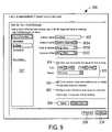
- FIG. 9is a screen shot depicting a call manager setup screen wherein some calls are converted to voicemails, according to one embodiment.
- FIG. 10is a screen shot depicting a call manager setup screen wherein calls to different phone numbers are handled differently.
- FIG. 11a screen shot depicting an example wherein a current activity mode for a callee is displayed on a caller's device.
- FIG. 12is a block diagram depicting an architecture for implementing callee identification by means other than NANP telephone numbers, according to one embodiment.
- FIG. 13is a block diagram depicting an example of a detailed architecture for implementing the present invention according to one embodiment.
- FIG. 14is a block diagram depicting one architecture for implementing call management functionality according to the techniques of the present invention.
- FIG. 15is a block diagram depicting an architecture for implementing the present invention by integrating with a wireless carrier using WIN or CAMEL.
- FIG. 16is a block diagram depicting an architecture for implementing the present invention using DNP.
- FIG. 17is a table containing an example set of rules for a callee, including a set of op-codes.
- FIG. 18is a block diagram depicting an architecture for implementing a disaster-resilient DNP architecture according to one embodiment of the present invention.
- FIG. 19is an example of a call routing matrix according to one embodiment.
- FIG. 20is a block diagram depicting an architecture for in-network and out-of-network call routing using an implementation of the present invention.
- FIG. 21is a block diagram depicting an architecture for a communication remote control system according to one embodiment.
- calleeis used to refer to an individual or entity that is being called or that may be called at some point in the future.
- the term “user”is used interchangeably with “callee.”
- a “caller”is a person who places a call to a user, or attempts to place a call, or potentially could place a call.
- dialed telephone number(dialed TN) is a number dialed by a caller. It may or may not be associated with an actual telephone device.
- a “delivery telephone device”is a device that can be used to receive calls.
- a “user profile”is a set of user configuration information specifying call management parameters.
- a “mode”is a callee's operational mode, such as “At Home,” “At Work,” etc. As described below, a mode can be selected explicitly by a user or implicitly according to the user's profile.
- a “filter”is a defined scheme for identifying a subset of a user's potential callers and to treat calls from them in a distinctive way.
- TNtelephone number
- NANPNorth American Numbering Plan
- a callercan specify a callee using any type of caller identifier, whether a dialed TN, a text string, a non-NANP digit sequence, or the like.
- UUser Address
- Delivery Telephone Numberrefers to the telephone number (or UA) of the device or system that terminates a call for, or to, a user.
- Delivery TNsconnect to delivery devices such as a telephone, a voicemail platform (traditional or e-mail delivery only), attendant Interactive Voice Response (IVR) system, or the like.
- a Dialed TN(the TN that the caller dialed) may or may not have the same number as one of the callee's Delivery TNs; a call to the Dialed TN may or may not be connected to the device addressed by the identical Delivery TN.
- a Dialed TNis virtual and is not the address of a physical delivery device.
- the present inventionmanages a callee's set of UAs and the real-time mapping of those UAs to delivery devices. Calls placed to a UA may be routed to one (or more) of the delivery devices corresponding to Delivery TNs.
- the systemuses a combination of modes, filters, caller selection (attendant), busy state, and no-answer state to determine whether and how a call should be routed to an appropriate delivery TN.
- the present inventioncan be implemented in symmetric or asymmetric fashion.
- a symmetric implementationis one in which all delivery TNs are in the set of dialed TNs; otherwise the implementation is asymmetric.
- Call management systemshandle the routing of telephone calls to various TNs of a user.
- a telephone service providermay route the telephone call directed to it based on user set call management directives or according to directives the provider determines based on user activity.
- a remote call management systemmay handle the routing of telephone calls directed to any of a user's service providers, including multiple providers.
- the remote call management systemmay store centrally call information and voicemail, and handle the routing of telephone calls directed to a plurality of user TNs.
- the usermay configure the remote call management system using a wireless client device.
- Architectures for call management systemsare illustrated in FIGS. 1-20 .
- An architecture for a remote call management systemis illustrated in FIG. 21 .
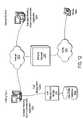
- FIG. 1there is shown a block diagram depicting an architecture for implementing the present invention according to one embodiment.
- Caller 101places a call via a local phone switch 102 such as Central Office (CO), Mobile Switching Center (MSC), or Private Branch Exchange (PBX).
- the callgoes through public switched telephone network (PSTN) 103 to destination switch 104 such as CO 104 A, MSC 104 B, or PBX 104 C.
- PSTNpublic switched telephone network
- Destination switch 104queries call management module 105 to determine where to route the call.
- Module 105checks user profile database 105 A to obtain call management settings for users.
- external input 120(such as callee location, caller identifiers, and the like) is also used by module 105 to determine where to route the call.
- Module 105sends a response to switch 104 indicating the desired routing for the call.
- the appropriate delivery device 108(including for example home telephone 108 A, wireless telephone 108 B, office telephone 108 C, voicemail platform 106 , and/or the like), is given the call, and the device handles the call as though it were received directly. Callee 109 then receives the call via the selected delivery device 108 .
- voicemail platform 106when voicemail platform 106 handles a call, it can query module 105 to determine whether a voicemail message should be delivered as an email attachment 110 to email reader 111 for receipt by callee 109 . In another embodiment, when voicemail platform 106 handles a call, it can activate an alert (e.g. a flashing light, a tone, or an indicator on a display) on any or all of delivery devices 108 , according to callee preferences as indicated in module 105 .
- an alerte.g. a flashing light, a tone, or an indicator on a display
- each query from destination switch 104includes, for example, the dialed TN and the caller TN (if known).
- module 105in response to receiving a query, returns a destination TN which may represent a delivery device 108 corresponding to the dialed number, or another device 108 , or voicemail platform 106 .
- Voicemail platform 106can be in the same network as destination switch 104 , or it can be accessible over PSTN 103 .
- voicemail platform e-mail delivery query 107includes the dialed TN and the caller TN (if known).
- module 105provides a delivery flag (yes or no), and an e-mail address.
- the present inventioncan be implemented in connection with any type of telephone system, including home telephones, office telephones, and wireless telephones, regardless of telephone equipment and regardless of telephone service provider.
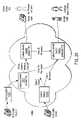
- FIG. 14there is shown a block diagram depicting one architecture for implementing call management functionality according to the techniques of the present invention.
- caller 101places a call to callee 109
- the callis routed to callee 109 based on rules stored in service database 105 A.
- Caller 202may call a landline TN or wireless TN of callee 109 .
- FIG. 14illustrates “post-ring” management of the call.
- Landline phone 1420is rung by connected CO switch 102 A 1 in LEC 1401 .
- PSTNPublic Switched Telephone Network
- Mobile Switch (MSC) 104 Bsends a query over SS7 network 1403 through one or more Signaling Transfer Points (STP) 1404 through signaling gateway 1407 to Application Processor 105 B.
- STPSignaling Transfer Points
- Application Processor 105 Bqueries database 105 A and returns a reply containing routing information that will be used by Mobile Switch 104 B to route the call. Possible routing destinations include callee's 109 wireless phone and carrier's voicemail platform 106 .
- queries from Mobile Switch 104 Bmay pass through the Home Location Register (HLR) 1402 .
- HLRHome Location Register
- caller 101places a call to the callee's 109 wireless phone, rather than callee's wireline phone 1420 , the call is routed from originating switch 102 A 2 , through PSTN 103 to MSC 104 B. MSC 104 B manages these calls “pre-ring,” before the mobile phone is rung.
- caller 101is connected to an automated attendant (Interactive Voice Response, or IVR; not shown in FIG. 14 ).
- IVRInteractive Voice Response
- MSC 104 Bcan be instructed to temporarily connect caller 101 to voicemail platform 106 in a way that causes voicemail platform 106 to play prompts under the direction of an Application Processor (not shown) by way of Messaging gateway 1408 .
- Callsmay also be managed in an Enterprise 1413 .
- PBX 1411queries the service for routing information and voicemail 1412 may be used in the enterprise.
- signaling gateway 1407 , database 105 A, application processor 105 B, and messaging gateway 1408communicate with one another via Local Area Network (LAN) 1406 .
- components of enterprise 1413communicate with one another via Local Area Network (LAN) 1409 .
- LANs 1406 and 1409communicate with one another using Internet Protocol (IP) 1202
- IPInternet Protocol
- LAN 1406communicates with VM 106 using IP 1202 .
- Gateway 1410connects LAN 1409 to PSTN 103 .
- STP 1404communicates with signaling gateway 1407 via SS7 1405 .
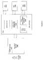
- user profile database 105 Astores the following information in order to specify a callee's call management settings:
- call management settings described aboveare specified by the user via a user interface such as a website, via a cell phone or PDA, or by default initial setup. Configuration may be performed by a third-party using an API. Mode selection can also be made directly or through an API.
- the followingis a description of a software-based call management system configurable by the callee to route incoming calls that are originally dialed to any of the callee's managed phone numbers, according to the callee's indicated preferences.
- the calleecan specify that different incoming calls should be routed to any of a number of different delivery devices, based on any combination of factors including, for example, the number the caller dialed, the identity of the caller, the location of the caller, environmental conditions at the callee's location, and real-time callee and/or callee input at the time the call is attempted.
- the calleespecifies such configuration options via a web-based user interface that facilitates communication with call management module 105 .
- a web-based user interfacethat facilitates communication with call management module 105 .
- FIGS. 2-7 and 9 - 10there are shown screen shots depicting an example of a web-based front-end that can be used for such call management configuration.
- these screen shotsare merely exemplary, and that many different arrangements and user interface elements can be used without departing from the essential characteristics of the present invention.
- the user interfaceneed not be web-based, and that any other type of user interface for accepting callee configuration of the system can be used.
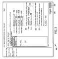
- FIG. 2there is shown a telephone setup screen 200 .
- the user interacting with the screensis the callee; however, the user could be another individual who is configuring call management parameters on behalf of a callee.
- the userenters a home phone number in field 201 A, mobile phone number in field 201 B, and office phone number in field 201 C.
- the usercan enter any number of additional phone numbers in field 201 D, and can specify descriptions for additional phone numbers via pull-down menu 202 .
- Other optionscan also be entered, including:
- Callers on the VIP listget special treatment.
- the systemcan be configured to allow calls from VIP callers to get through even when normal calls would be routed to voice mail or screening. Calls from numbers (people) in the user's VIP list skip through any “Screen” settings as their calls are considered emergency calls in the context of screening. Such a technique is referred to herein as “filtering”.
- Link 205provides access to a VIP list management screen for adding, editing, and deleting names and numbers in the VIP list.
- FIG. 6there is shown a VIP list management screen 600 according to one embodiment.
- List 601shows current VIP entries.
- the usercan edit entries by clicking on an Edit link 602 , or delete entries by clicking on a Delete link 603 .
- Apply button 606applies the changes; cancel button 607 dismisses screen 606 without applying any changes.
- the usercan specify email addresses in fields 206 , 207 for call notification emails and for receiving voicemail, respectively.
- Buttons 208 , 209facilitate navigation to other screens in the call management setup application.
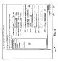
- call manager setup screens 300there are shown call manager setup screens 300 according to one embodiment.
- the usercan configure call routing for each mode (activity) the user defines. Modes in this example are “My Default”, “At Work,” “At Home,” and “Commuting”.
- the usercan select which mode to define from activity menu 301 .
- he or shecan specify the name for the mode (activity).
- Popup menus 303 A, 303 B, 303 Callow the user to specify how calls should be handled when they are received at the home number, mobile number, and office number, respectively.
- each popup menu 303allows the user to select among routing the call to a particular destination device 108 , to voicemail 106 , or to screen the call, or the like.
- Check box 304allows the user to enable a preset schedule for the mode. If check box 304 is checked, the mode will automatically be activated at the times specified in popup menus 305 .
- Check box 306allows the user to select whether text notification should be sent to the mobile phone when a voicemail message is received.
- Check box 207allows the user to select whether an email message should be sent when a voicemail message is received.
- Apply button 308applies the changes indicated by the user.
- Delete activity button 401deletes the mode (activity) from menu 301 .
- Navigation buttons 208 , 209allow the user to navigate to other call setup screens.
- the userhas configured the “My Default” activity so that calls to home, mobile, or office are routed to the respective delivery devices.
- the userhas configured the “At Work” activity so that calls to home are sent to voicemail and calls to both mobile and office are sent to the office. This mode is scheduled to be active from 9 am through 5 pm every workday.
- Check box 306has been activated, so that text notification will be sent when voicemail is received.
- the userhas configured the “Commuting” activity so that calls to home are screened to the mobile phone and calls to mobile or office are connected to the mobile phone.
- a messageis played to the caller; “The person you are trying to contact is currently unavailable, if this is an emergency press 1, otherwise press 2 to leave a message.” If the caller presses 1, he or she is connected to the mobile device. If he or she presses 2, he or she is connected to the voicemail platform.
- FIG. 7there is shown an example of a call management summary screen 700 according to one embodiment.
- a summary 701 of settingsis shown, with Edit buttons 702 allowing the user to return to a screen for changing settings.
- the usercan select which mode is active by clicking on one of radio buttons 703 .
- Apply button 704applies the changes.
- the usercan select among modes by other means as well.
- FIG. 8there is shown an example of a user interface for selecting among modes via a mobile phone handset 800 .
- the system of the present inventionactivates different modes depending on any of: explicit selection, time of day (and/or day of week), location of the callee (detected, for example by GPS positioning, or by noting that the user has used a particular phone recently, or by explicit user indication of location).
- scheduled modesare automatically active during scheduled times. In one embodiment, scheduling can be turned on or off from the handset or from the website.
- a call routing matrixcan be constructed. Referring now to FIG. 19 , there is shown an example of a call routing matrix 1900 according to one embodiment.
- Matrix 1900summarizes call handling preferences according to callee mode and caller identity. Each row in matrix 1900 represents a mode, and each column represents a filter option (a particular caller or caller group). Current mode 1904 is also shown.
- matrix 1900provides input fields for specifying additional call routing configuration options.
- pull-down menus 1901allow the user to schedule certain modes and/or to specify how mode activation can be automatically handled based on location or other factors.
- Pull-down menus 1902allow the user to switch manually to a desired mode.
- Link 1903allows the user to access additional edit options.
- any or all of the summary information and input fields of FIG. 19can be shown in the context of other types of user interfaces, including for example an interface for a PDA or cell phone screen.
- module 105directs the call based on any combination of the following factors: call routing rules as specified above, currently active mode, caller identification (or lack thereof), called telephone number, mode, and caller or callee input as described above.
- call routingmay also be determined by the system based on routing decisions the user has made in the past.
- the present inventioncan use intelligent call management algorithms, including for example collaborative filtering based on the behavior of a set of users, to learn about users' preferences without requiring explicit selection.
- the systemcan automatically route calls to callees in that location to voicemail, while sending a SMS notification to the callee.
- locationswhere such a situation may occur are a movie theater and a lecture hall.
- the systemcan determine these location behaviors empirically, for example based on system usage.
- the systemcan use a database of location classifications to extrapolate a user's behavior (or set of user's collaborative behavior) from one location to another location of similar classification.
- call handlingis accomplished as follows.
- a database queryis made before the call is completed.
- the result of the database querycauses the call to complete to the originally dialed device (device associated with the managed telephone number), to be redirected to another delivery device (which may, or may not, also be in the set of managed telephone numbers), or to be redirected to the system handling the user's voicemail.
- the call routingis thus performed in a manner that is seamless to both the caller and the callee.
- system of the present inventionimplements rule-based routing based on the data stored in database 105 A.
- Rulesare implemented in a manner that resembles operands. For any given call management situation, only one rule is executed, so as to definitively dispose of the call.
- the rulesare created by program logic, on a web server and in database 105 A, when callee 109 configures his or her account.
- a determinationis made as to which single rule is to be executed by the switch. If more than one callee 109 shares the managed phone line (managed TN), a single rule is identified for each callee 109 and returned to the querying server (“telephone server,” Signaling Application Processor, etc.). That server causes the caller to be asked which user they are calling. (For example, “Press 1 for Joe; Press 2 for Jane”) After that selection is made by the caller, the appropriate call-routing rule is executed.
- database 105 Astores a representation of a chart for a particular callee 109 ; the chart sets forth a set of rules.
- Each ruleis qualified by any or all of the following:
- each ruleis an action (or more than one action), also referred to as op-codes. Examples include:
- database 105 Aincludes a representation of a number of rules, each including any or all of the above.
- callee 109 modescan be based on explicit selection, or on location, or by a schedule, or by other predetermined conditions. In one embodiment, certain modes may expire automatically after a defined period of time; then, the callee 109 returns to a default mode or previous mode.
- the schema and indexing of the tableis designed to facilitate rapid lookup during call-handling operation.
- a switchLEC, MSC, PBX, etc.
- the system of the present inventiondoes the following:
- the “instruction” part of the selected ruleis returned.
- This instruction partconsists of an opcode and some operands. These are: opcodeID, deliveryDeviceID 1 , deliveryDeviceID 2 and 2 notification options: callNotifyEmailOption and callNotifySMSOption.
- the deliverDevicelDsreference telephone numbers stored elsewhere in the database. When the rule instruction is returned, by the database, to the querying server telephone numbers are returned instead of deliveryDeviceIDs.
- the associated rule instruction(or op-code) is executed.
- callNotifyEmailOption and callNotifySMSOptionare notification options which, if set to ‘Y’, cause the system of the present invention to send a call notification to callee 109 using an address stored elsewhere.
- the followingis an example of a set of op-codes for use by the system of the present invention.
- One skilled in the artwill recognize that many other types of op-codes can also be used.
- the op-code “CONNECT_DIALED_DEVICE”is transformed to “CONNECT” by database logic before being returned to the querying server (“telephone server”) using information available at call time (specifically the called number).
- the opcode “CONNECT_INTERNAL_VM”is transformed to “VOICEMAIL” if the voicemail access number stored in the database is handled by the same telephone server that is making the database query; this direct internal connection saves the resources required to place an additional call.
- voicemail platform 106 and other enhanced servicescan be provided by any provider and need not be associated with the provider of module 105 .
- a usercan have any number of voicemail repositories, though many users will find it convenient to direct all voicemail calls to a single voicemail repository.
- the usermay select a voicemail service and repository provided by one of the carriers that the user is using for telephone service.
- the usermay select voicemail service from a third-party provider that is not associated with any of the user's phones.
- the userwhen initially signing up for call management services such as those provided by the present invention, the user can select a voicemail service provider from a list of available providers.
- module 105directs the call to the appropriate voicemail access phone number.
- unanswered callsbusy or no answer after four rings are also routed to the appropriate voicemail access phone number.
- call notificationvia email, SMS message, Stutter-Dial-Tone, and the like
- integrated call loggingone list of incoming calls across all of a user's managed phones
- the system of the present inventionperforms real-time mapping and rule selection on call-by-call basis.
- inputsare evaluated at the time the call comes in, so as to select the rule based on the most up-to-date information.
- the present inventionensures that calls are correctly routed based on the most current sources of information and settings.
- the call management system of the present inventionallows a user (callee) to control how they are reached by phone.
- the callis routed pursuant to the desire of the user.
- incoming callsmay be routed, for example, to the phone at the callee's current location or to voicemail (if they consider themselves unavailable for phone calls).
- a callercan identify a callee to be called by some identifier other than the telephone number (in other words, an identifier that is not in conformity with the North American Numbering Plan (NANP) for telephone numbers).
- NANPNorth American Numbering Plan
- the callermay initiate a call via a web interface, PDA interface, cell phone interface or by some other means.
- the callermay select or enter the callee's name or email address, or may even click on a link on a web page to attempt to reach the callee.
- the caller's actioncauses module 105 to perform a database lookup and to initiate a telephone call to callee according to the current mode and callee preferences, as described above.
- callsare routed in a similar manner as above but the caller has identified the callee by means other than the telephone number.
- the calleecan specify that calls initiated by identifying the callee by some mechanism other than telephone number are handled differently than calls initiated by dialing a telephone number.
- a call initiated by selecting a name from a web pagemight go to voicemail, while calls initiated by dialing a telephone number might be routed to the callee's wireless phone.
- Such a mechanismcan be implemented for example by providing one or more additional pull-down menus in the screen shown in FIG. 3 , allowing selection of actions to be taken if the callee is called using alternative identifying means.
- FIG. 12there is shown a block diagram depicting an architecture for implementing callee identification by means other than telephone numbers, according to one embodiment.
- a callerplaces a call, for example via computer 1201 that is running a voice communication application.
- the calleridentifies the callee by some means other than entering a NANP telephone number, for example by entering the callee's e-mail address.
- the application running on computer 1201contacts call management configuration storage and routing module 105 to determine how to route the call. Based on callee preferences, routing module 105 causes the call to be routed to another computer 1204 or to a NANP device such as telephone 108 A connected to PSTN 103 via an IP/PSTN gateway 1203 . In one embodiment, the call is routed from computer 1201 to gateway 1203 or to computer 1204 via the Internet 1202 .
- non-NANP callscan be placed using Voice over Internet Protocol (VoIP). These calls can be initiated using Session Initiation Protocol (SIP).
- VoIPVoice over Internet Protocol
- SIPSession Initiation Protocol
- call management module 105can be registered (with a network SoftSwitch) to handle the callee's VoIP telephone calls.
- the SoftSwitchsends an “Invite” message to call management module 105 .
- Call management module 105responds with a redirection message that causes the SoftSwitch to either complete the call as originally directed or to terminate the call on another device (VoIP/SIP phone, PSTN phone, or voicemail platform).
- the present inventionprovides distinctive ring tones based on any of a number of factors, including which number was dialed, caller identification, or the like.
- Call management screencan be enhanced in one embodiment by adding user interface elements that allow the user to specify different types of call notification depending on certain conditions.
- the notificationcan be, for example, a distinctive ring on the delivery device or a distinctive Instant Message notification on a computer.
- a usermay specify that calls routed from his or her office phone ring to his or her home phone using an alternate short-ring-cycle distinctive ring, while other calls use the standard ring.
- the ring typecan be controlled by routing the call to one of two phone numbers associated with the telephone line using a standard LEC (Local Exchange Carrier) “distinctive ring” feature.
- LECLocal Exchange Carrier
- the ring type on a mobile phonemay be modified in real time immediately before the system routes a call to that phone by sending a Short Message Service (SMS) message (or other data message) to a software application running on the phone.
- SMSShort Message Service
- the software applicationchanges the phone ring type according to instructions sent in the SMS message.
- the present inventionuses an alternative communications path, such as short message service (SMS), email, instant messaging, or the like, to let the callee know who is calling.
- SMSshort message service
- the message to the calleecan include additional information about the call, including how it was routed, where the caller is located, caller's telephone number, caller's name (from the user's directory or from other sources such as a CNAM database), number dialed by the caller, and the time of the call and the like.
- the calleecan specify which incoming calls should include such notification, and what type of communications path/mechanism should be used.
- Email notification of callsmay also be configured.
- the content of the notificationmay include the caller's telephone number, the caller's name (from the user's directory or from other sources such as a CNAM database), the number dialed by the caller, and the time of the call. In alternative embodiments, other types of information may be included.
- Call management module 105when Call management module 105 receives a query from a telecom switch 102 or PBX 104 C, it dips User profile database 105 B to determine how to respond to the query. Information returned from database 105 B includes a callee notification configuration. This information includes how to send notification to callee 109 and in what format to send it. In the case of e-mail notification, Call management module 105 formats an e-mail message and sends that message over the Internet through an mail (SMTP) server.
- SMTPmail
- the present inventioncan convert telephone calls into email messages, SMS messages, instant messages, or other types of communications.
- call management screen 300is enhanced in one embodiment by adding user interface elements that allow the user to specify that certain telephone calls (depending on any of the factors discussed above), should be converted to other types of communications.
- menu 303 Aincludes a “send to voicemail” option that allows the callee to specify that while at work, calls to his or her home number should be sent to voicemail.
- the systemcan further be configured to convert the voicemail to an email message or to attach it to an email message and send it to the callee's work email address.
- Content of the communicationcan include additional information about the call, including how it was routed, where the caller is located, caller's telephone number, caller's name (from the user's directory or from other sources such as a CNAM database), number dialed by the caller, and the time of the call and the like.
- this information about the call and the calleris compiled from information passed in the query to the Call management module 105 combined with derived information (for example a directory lookup of the caller's name based on the calling telephone number) and independent information such as the time the call was processed by the system.
- voicemail platform 106queries module 105 to determine whether to deliver a voicemail message using e-mail.
- Module 105obtains profile information from database 105 A. This determination is made based on user preference as a function of any or all of mode, callee, and dialed telephone number.
- the present inventionfacilitates mapping of different phone numbers to different modes.
- several telephone numberscan be established; for example, one for important calls, one for business calls, one (or more) disposable numbers, and the like.
- Such an arrangementallows the callee to better manage his or her calls by giving out the appropriate number from the set of telephone numbers, depending on the situation.
- the various telephone numbersneed not have any correlation to actual physical locations or telephones.
- call management screen 300wherein calls to different phone numbers are handled differently.
- the userwhen the user has selected the “High Priority” mode, only calls to the mobile phone will ring through. Calls placed to home and office phones will be routed directly to voicemail. Thus, the user can give out the mobile phone number to those callers whom the user deems most important.
- a disposable telephone number(valid for a limited time period) can be offered. Calls made to temporary (disposable) telephone numbers are routed to one of the user's delivery devices or to voicemail, depending on the user's stated preferences. The assignment of a temporary number can be made dynamically from a pool of available numbers. The number may remain valid for a single call, for a brief time period, or for a long time period.
- a temporary telephone numberis as a contact number for people communicating using Internet Chat.
- a temporary numbercan be provided as a “public” number for a user allowing that user to give the telephone number to another person to make a single call.
- the user's actual delivery device telephone numbersremain private. After use, the telephone number is suspended for some period of time and then returned to the pool of available temporary telephone numbers.
- a temporary address numberis given to the user along with a common access number.
- a common access numberfor example, a toll-free number
- the callerenters the temporary address number (a sequence of digits).
- the callis then routed to the appropriate user's delivery device or voicemail.
- the systemgenerates a temporary address number, for example a unique digit string that is valid for a limited time.
- a callercalls the common access number, it is answered by a telephone server (not shown).
- the telephone serverqueries User profile database 105 A.
- Database 105 Atreats the temporary address number as a managed address for purposes of determining the routing rule to pass to the telephone server.
- the telephone serverexecutes the routing rule, which results in sending the call to a telephone, voicemail, or some other call handling device.
- the present inventioncan split off calls for those with other phones (wireless or office) as defined in the configuration profile.
- potential callerscan see mode information for callees. In one embodiment, callees can choose whether or not to make such information available to potential callers. Additionally, callees can choose to make such information available only to some potential callers, if desired.
- a potential callercan see mode information by keying in the phone number of the callee in a cell phone or other device, or by selecting the callee from a directory, or by some other means.
- the calling devicequeries the system of the present invention to obtain a description of the callee's current mode. A representation of that mode is displayed the potential caller, who can then decide whether or not to attempt to complete the call.
- a callee's mode informationis a label that reflects the callee's desire, ability, or propensity to accept any, or certain types of, phone calls.
- User B's modecan be presented to User A before and/or after User A places a call to User B.
- mode informationis presented to User A before a call is placed to User B, User A can use knowledge of User B's mode in deciding whether or not to initiate a call to User B. If mode information is presented to User A after a call is placed to User B. User A can use that knowledge as context for discussion with User B if the call is picked up by User B or for understanding why the call was not picked up by User B.
- the displayed modemay be set explicitly by that callee or it may be a function of the callee's mode; in other words, the callee may specify that the displayed mode not be the same as the actual mode. All inputs used to determine mode can also be used to algorithmically determine the user's mode.
- User Amay learn of User B's mode by viewing an address book entry on a client device (mobile phone or other device), by selecting a “show mode” soft-key on a client device, or by some other means on the client device. User A may also learn of User B's mode after calling User B.
- Callee mode informationcan be determined when another user queries for it or it can be determined periodically by the system. If the mode is determined periodically, it can be stored and made available for query or it can be pushed to the client devices of all users who have access to the information.
- FIG. 11there is shown an example of a cell phone display wherein a current activity mode 1101 (Home) for a callee is displayed. This display would be shown, for example, after the user of the cell phone had keyed in the telephone number of the callee on keypad 1102 (or after he or she had selected the callee's name from an on-screen list or directory).
- Homea current activity mode 1101
- the display of the modeindicates whether the callee is at home, at work, on vacation, or the like.
- additional informationcan be displayed, such as the callee's activity mode schedule, an indication of when the current mode will change and what the next mode will be, forwarding information (such as substitute telephone number), or any combination thereof.
- the calleecan specify what kind of information is displayed, and can indicate that different kinds of information be made available to different callers or depending on other factors.
- the system of the present inventionis implemented as follows. First a call being made is intercepted as follows:
- a database dipis performed to determine how to dispose of the call. Disposition options are: let it complete, forward it elsewhere, or send it to voicemail.
- the database dipis performed on a specialized database or mirror. Interfaces to the database include AIN/WIN/CAMEL to an SCP via SS7 or XML via the Internet.
- Database dipsmay be made directly or through a partner that runs the SS7 network as a front-end to the database, either by contacting the database in real-time (pull) or hosting a mirror of the database (push).
- FIG. 13there is shown an example of a detailed architecture for implementing the present invention according to one embodiment.
- the wireless network shownis a GSM network.
- CDMA and other wireless protocolsare also supported.
- a redundant centralized configurationis shown in the example of FIG. 13 .
- the inventioncan also be implemented using, for example, a geographically distributed architecture.
- SS7 Network 1301provides the SS7 connectivity between service platform 1304 and Wireless Carrier Network 1303 .
- a networkmay be provided, for example, by a wireless telephone company such as Verizon.
- a wireless telephone companysuch as Verizon.
- One skilled in the artwill recognize that other mechanisms for connecting components 1304 and 1303 can be used.
- IPInternet protocol
- ILEC SS7 Network 1302is used to turn message waiting on and off on landline phones. Elements in 1301 and 1302 are optional components that need not be included in order to practice the present invention.
- MSC 1321when a call addressed to a managed telephone number is received by MSC 1321 , MSC 1321 sends a query containing the called TN and calling TN to Application Processor-SCP 1330 using a TCAP message over the Signaling System 7 (SS7).
- This messagetravels over one or more Service Transfer Points (STP) 1315 , 1306 in SS7 network 1312 and through Signaling Gateway 1326 , where its format is converted to SCCP-User Adaptation Layer (SUA).
- STPService Transfer Points
- SAASCCP-User Adaptation Layer
- the querycan travel over Internet Protocol (IP) network 1325 from MSC 1321 through Edge SS7 Gateway 1316 to Application Processor—SCP 1330 using the SIGTRAN protocol.
- IPInternet Protocol
- the Application Processoracts as an Intelligent Networking Service Control Point (SCP) 1330 .
- SCP 1330queries the Database 1329 to determine how to handle the call. In some cases, for example if the managed TN is shared among multiple users, caller 101 is prompted to enter a digit to select the desired callee (or to select the callee by other means). To do this, SCP 1330 establishes a session and responds to MSC 1321 , instructing it to temporarily connect the call to Application Processor—Intelligent Peripheral (IP) 1332 through VoiceXML gateway 1328 over PSTN or using VoIP.
- IPIntelligent Networking Service Control Point
- IP 1332When Application Processor—IP 1332 receives a call, it communicates with Application Processor—SCP 1330 over Internet Protocol 1331 to determine which voice prompt to play to caller 101 . The response from SCP 1330 is used to select and retrieve the voice prompt from Prompt store 1333 . That prompt is played to caller 101 . Caller's 101 selection, made for example with the Dual Tone Multi-Frequency (DTMF) signal from a key press on a conventional telephone, is detected and forwarded to SCP 1330 . Application processor—SCP 1330 uses the caller's selection to determine how to dispose of the call. Instructions for call disposition are sent to MSC 1321 .
- DTMFDual Tone Multi-Frequency
- MSC 1321disconnects the call to Application processor—IP 1332 and forwards the call to the desired delivery TN.
- Callee 109can be notified of unanswered call events by the system. Desired call event information is sent from database 1329 to Notification Server 1334 , which can notify callee 109 in various ways including sending an Short Message Service (SMS) message to callee's 109 mobile phone via SMS Gateway.
- SMSShort Message Service
- PBX 1336An enterprise telephone (station) attached to a Private Branch Exchange (PBX) 1336 can be managed by the system.
- PBX 1336sends a query to Application Processor—SCP 1330 over Application Programming Interface (API) 1337 .
- APIApplication Programming Interface
- the response from the queryinstructs PBX 1336 as to how to dispose of the call.
- Voicemail messagesmay be interchanged between Wireless Carrier Voicemail platform 1320 and Enterprise Voicemail platform 1335 using VPIM Gateway 1340 .
- call routing(also referred to as vectoring) is accomplished by forwarding from destination switches 104 (connected to the originally dialed TN in a Central Office (CO) 104 A or Mobile Switching Center (MSC) 104 B or by forwarding from Private Branch Exchanges (PBX) 104 C controlling dialed office telephones.
- COCentral Office
- MSCMobile Switching Center
- PBXPrivate Branch Exchanges
- Advanced Intelligent Network (AIN) technologyis used in CO 104 A.
- Advanced Intelligent Network (AIN)is a telephone network architecture that separates service logic from switching equipment, allowing new services to be added without having to redesign switches to support new services.
- Wireless Intelligent NetworkWIN
- Customized Applications for Mobile network Enhanced LogicCAMEL
- MSC 104 BMSC 104 B to implement the call management functionality described herein.
- FIG. 15there is shown an example of an architecture for implementing the present invention by integrating with a wireless carrier using WIN or CAMEL.
- the implementation shown in FIG. 15manages landline, wireless, and office telephones using the wireless carrier Mobile Switching Center switch (MSC) 104 B.
- MSCMobile Switching Center switch
- Calls placed to Home phone 108 A of callee 109are initiated by any phone 101 A, 101 B, 101 C and are routed over PSTN 103 to Central Office (CO) 104 A associated with called home phone 108 A. If Home phone 108 A is busy or not answered, the call is forwarded to MSC 104 B where the call is managed.
- MSCMobile Switching Center switch
- calls placed directly to the callee's Wireless phone 108 Bare managed at MSC 104 B.
- Calls placed to the user's office phone 108 Care managed by MSC 104 B if the callee's public TN (published TN). is forwarded by PBX 104 C to MSC 104 B and Office phone 108 C is associated with a hidden TN. In this fashion, calls destined to the callee's Office phone 108 C arrive at MSC 104 B where they can be managed and potentially forwarded to the actual office phone using the private TN.
- MSC 104 BUpon receipt of a call for a managed TN, MSC 104 B queries SCP 1501 inside Call Management Module 105 using a WIN or CAMEL trigger over SS7.
- SCP 1501 in this figureincludes a service database and database logic 102 , which determines how the call should be handled by MSC 104 B.
- a promptis played to caller 101 so that caller 101 can select the callee he or she is trying to reach.
- the spoken name of each useris originally stored in the Master copy of prompts 1503 and periodically copied to a mirror data-store at MSC 104 B.
- MSC 104 Buses the local copy of the prompts to ask caller 101 to select a callee 109 (for example, “Press 1 for Joe. Press 2 for Mary,” and the like).
- the selectionis sent to SCP 1501 , which replies to MSC 104 B with instructions for completing the call.
- MSC 104 Bmay forward the call to the callee's Wireless phone 108 B, Office phone 108 C, or to a voicemail platform (not shown in FIG. 15 ), or the like.
- the callwould not be forwarded to Home phone 108 A because phone 108 A is already known to be busy or not answered.
- the service databasecan be configured with a computer 1506 through a Website 1504 or through telephone Interactive Voice Response (IVR) system 1505 .
- IVRInteractive Voice Response
- FIG. 15The architecture of FIG. 15 is set up to provide the functionality of the present invention using one or more of the following steps:
- Home phone 108 Ais provisioned to forward to cell phone TN on Busy or No-Answer.
- one or both of the following techniquescan be used:
- Office phone 108 Cis provisioned in PBX 104 C to forward to cell phone TN on Busy or No-Answer, or office phone forwarding (variable or BNA) can be dynamically configured based upon mode and/or filter.
- a switch in MSC 104 Bconnects to cell phone 108 B or redirects to another phone 108 C, 108 A or voicemail 106 based upon mode and filters.
- the callis forwarded to the cell phone switch.
- all callsgo to MSC 102 B before ringing home phone 108 A.
- a switch in MSC 102 Bcan play attendant prompts to allow caller to select one of multiple users via IVR.
- the switch in MSC 104 Bcan connect to cell phone 108 B or redirect to another phone 108 A, 108 C or voicemail 106 based upon mode and filters.
- a switch in MSC 104 Bconnects to cell phone 108 B or redirect to another phone 108 A, 108 C or voicemail 106 based upon mode and filters.
- Attendant prompts 1503may be recorded at a central site and distributed to each of the MSCs 102 B through data mirroring.
- An SSP 1705 at MSC 104 Bcan use an Intelligent Peripheral, located at MSC 104 B or centrally, to play attendant prompts.
- Advanced Intelligent Network (AIN) functionality at destination switch 104can be used to perform filtering and/or play attendant prompts before ringing home phone 108 A.
- the callcan be forwarded to home phone 108 A (possibly using distinctive ringing to identify the desired user), the call can be sent to another phone (including a cell phone 108 B or office phone 108 C), the call can be routed to a voicemail platform 106 , or the call can be routed to another service.
- callee 109can specify filters that allow certain callers 101 skip the attendant or to be handled differently than other callers.
- Adding a caller 101 to a filter listcan take place at any time, including after a call is completed, or before or during a conversation, or at any time using a configuration tool such as described above.
- the web-based user interfacedisplays a log of incoming callers, call times, the user the caller selected, along with the controls necessary to add/remove callers to/from filters.
- FIG. 16there is shown another embodiment of the present invention, wherein the functionality described above is implemented using Dynamic Number Portability (DNP), substituting the Alternate TN at the Origin and/or Gateway switch.
- DNPDynamic Number Portability
- Caller 101places a call on any of the following: a residential, inter-company or inter-carrier wireless phone 101 A; an Intra-carrier wireless phone 101 B; or an intra-company phone 101 C is Central office (CO) switch 102 A is associated with phone 101 A.
- Mobile switching center switch 102 Bis associated with phone 101 B.
- PSTNPublic Switch Telephone Network
- VMVoicemail
- CO switch 104 ACO switch 104 A.
- SS7 network 1405carries Non Call path Associated Signaling (NCAS) between switch 102 A or 102 B and call management module 105 .
- NCASNon Call path Associated Signaling
- Voicemail (VM) platform 106is a potential destination for calls that is capable of recording caller's 101 voice message.
- CO switch 104 Ais a land-line central office switch associated with home (residential) telephone delivery device 108 A.
- Mobile switching center (MSC) switch 104 Bis connected to wireless (mobile) telephone delivery device 108 B.
- Private branch exchange (PBX) 104 Cis connected to an office telephone (station) 108 C.
- callee 109configures the service of the present invention, for example using a computer or wireless phone software application 1506 . Examples of screen shots of such an application 1506 are shown in FIGS. 2-7 and 9 - 10 .
- Call Management Module 105includes Service Control Point (SCP) 1501 that accepts queries from switches 102 A, 102 B, 104 A, and PBX 104 C, and returns call routing information.
- SCPService Control Point
- PCM Mode, Filter and Redirect logic 1502 and PCM Attendant logic 1502 Aare software programs associated with SCP 1501 .
- Data store 1503contains master copies of user spoken names for use in prompting caller 101 to select from multiple users who share a managed home telephone.
- web configuration interface 1504generates the website with which callee 109 configures the service.
- callee 109can use telephone Interactive Voice Response (IVR) server 1505 to configure services.
- IVRInteractive Voice Response
- call managementis performed by doing a lookup at origin switch 102 A or 102 B (associated with caller's 101 telephone line 101 A or 101 B) or PBX 104 C, for example using Dynamic Number Portability (DNP).
- DNPDynamic Number Portability
- An advantage of such an implementationis that it reduces system-wide telecom costs and eliminates potential calling loops that may take place if different systems (such as PBXs) control redirection for overlapping subsets of a user's phones.
- DNPneed not be implemented in all networks to be effective at reducing costs associated with re-routing calls to alternate telephone numbers.
- DNPis implemented using universal switch (CO and MSC) participation and/or PBX participation to redirect intra-company calls to a user's office phone.
- DNPis also implemented at international gateway switches so that calls can be routed (vectored) when entering a particular service area.
- DNPis implemented at the call-originating device, for example when calls are transported without going thought telecom switches.
- Such a techniquecan also be used for devices that use PSTN 103 .
- Such devicesinclude a computer that places calls using IP telephony, a wireless carrier's cell phone, or a peer-to-peer switch-less cell phone.
- the call-originating deviceperforms a DNP database dip to receive the substitute TN and other call control information, such as TN to call if the substitute TN is not answered.
- switch 102 A or 102 Bdetermines the dialed TN is a user TN (optional step). If so, then a DNP dip is performed passing Dialed TN and Calling Party TN, Calling Party Blocked CID Flag, and a switch identifier (for location determination used in some cases for substitute TN selection). Returned from the dip is Substitute Telephone Number (STN), Busy Telephone Number (BTN) No Answer Telephone Number (NATN), No-Answer Ring Count (or time delay), and billing entity number (which may be a switch ID of user).
- STNSubstitute Telephone Number
- BTNBusy Telephone Number
- NTNNo Answer Telephone Number
- billing entity numberwhich may be a switch ID of user.
- Switch 102 A or 102 Bcalls the STN. If it is busy, the call is connected to BTN. If it is not answered after “No-Answer Ring Count” rings, the call is connected to NATN.
- the STNcan be a delivery device (wireline or wireless phone) or another device such as an attendant IVR service.
- destination switch 104 A, 104 B, or another destination switch for the delivery devicemay act as an attendant service.
- An attendant servicecan redirect the call, present caller 101 with options (such as attempt connection or go to voicemail, or allow caller 101 to select which callee he or she is calling from a list of options), or provide screening choices to callee 109 .
- an attendantcan call callee 109 and let him or her know who is on the phone, and present callee 109 with call completion options.
- BTN and NATNalso allows LECs to pull back a call destined to a wireless carrier. In this way, they can allow their customers to have a single voicemail box, possibly on the LEC network. This scheme enables a “leave a message for a person, not for each of their places” service.
- DNPalso enables a wireline carrier to allow its customer to hide a wireless TN behind a wireline TN.
- BTN and NATNin the returned DNP information also allows the owner of origin switch 102 A, 102 B to provide a voice messaging option to their customers, the callers.
- a servicecould be implemented, for example, by dialing *11 or other prefix code or access TN before a 10-digit number. If callee 109 is a DNP user and has a BTN and NATN, then caller 101 is connected to voicemail directly. If BTN and NATN is not present, then the *11 service can connect the call directly or inform caller 101 that the voice messaging option is not available. This scheme enables a “leave a message for a person, without the risk of talking to them” service.
- a BTN and NATN returned in a DNP dipmay differ depending on the switch making the dip.
- the DNP dipincludes switch ID that can be mapped to location inside the DNP system.
- DNPcan dynamically substitute local access numbers. This can be done, for example, to minimize the access charges in a voicemail network.
- the BTN and NATNare not typically configured directly by the user. Instead, the user selects a third-party VM provider, and that provider supplies access numbers.
- attendant greetingsare a function of filters and modes. For example, when caller 101 dials callee's 109 home TN, caller 101 might receive a different personalized greeting based upon callee's 109 current mode: “I'm commuting right now, please leave a message and I'll return your call when I reach my destination,” or “I'm at work today, please press 1 to connect to my office phone.”
- modes and/or filterscan be used to select ringing modes (loud, soft, vibrate, etc.) and/or ring tones (“Ring-ring, ‘you have a call’, etc.) on a cell phone or other phone, as described in more detail above.
- Origin switchdetermines if the TN is managed by DNP. In one embodiment, this information is pushed from a database (not shown) within SCP 1501 to the carrier periodically. In one embodiment, if this data is pushed to the carrier, the carrier uses an in-network SCP with an affiliated database (mirror of the data within SCP 1501 ) to query for call routing information. This step minimizes out-of-network SS7 traffic. This check to see if a user has DNP can be performed on an in-network LEC or wireless carrier database that is anticipated periodically, for example every 15 minutes. In one embodiment, if the user has DNP service, a DNP dip to a DNP database is done to get current data.
- DNP dipis performed, typically using Transaction Capabilities Application Part (TCAP) messaging carried on Signaling System 7 (SS7) 1405 .
- TCAPTransaction Capabilities Application Part
- SS7Signaling System 7
- SCPService Control Point
- the following informationis returned from DNP database, for example via TCAP message from SCP 1501 to SSP:
- DNP dipis performed, for example using XML over HTTP.
- the following informationis passed to DNP database:
- the following informationis returned from DNP database:
- DNPis implemented with a master database and a distributed network of mirrored databases in multiple geographically disparate locations.
- GTTGlobal Title Translation
- SCP 1501the active or best database
- SS7 network 1405may be provided by a third party.
- DNP dipsare only performed for dialed TNs of users of the DNP service.
- a pre-qualification databasemay be hosted by the LEC within its own network. Such an implementation causes DNP dip traffic to grow gracefully over time. In the event of a system failure, the default action is to complete the call to the original dialed number, if possible.
- the pre-qualification databasemay be updated at a frequency much lower than the update of the active DNP databases.
- the present inventioncan be implemented in many different architectures, and can operate regardless of whether call routing takes place at the origin switch or the destination switch, or at a gateway switch.
- call routingtakes place at an origin switch.
- call routingcan take place at any other switch along the call path.
- multiple routingscan take place at different points along the call path.
- a DNP dipcan be made at any point in order to obtain information for the call routing operation.
- multiple DNP dipsmay occur, as requested by multiple switches.
- a flagmay be set to indicate that a DNP dip has already occurred for the call, so that additional unnecessary dips can be avoided.
- FIG. 20there is shown an example of an architecture for in-network and out-of-network call routing using an implementation of the present invention. Two cases are contrasted:
- Case 1In Network Caller.
- origin switch 102 AAre-routes the call to Alternate TN 108 B via switch 104 AC.
- Case 2aOut of Network Caller.
- gateway switch 2001re-routes the call to Alternate TN 108 B via switch 104 AC.
- Case 2bOut of Network Caller.
- caller 101 B not belonging to network 2002dials callee 109 at dialed TN 108 A
- gateway switch 2001or any other switch, does not re-route the call
- callee's destination switch 104 ACcan e-route the call to the Alternate TN 108 B.
- origin switch 102forwards calls on behalf of caller 101 .
- Callee 109is not necessarily a customer of the owner of origin switch 102 .
- the present inventionuses DNP and includes a charge transfer sub-system.
- billing recordsare moved from origin switch 102 to an entity, which can bill the customer.
- the billing recordcan be forwarded to the switch of the dialed number. Callee should be charged the cost as if the call was forwarded from the switch associated with the originally dialed TN to the forwarded number.
- the present inventionprovides automatic and/or preconfigured redirection of telephone calls in case of emergency or disaster.
- an “Emergency” modemay be predefined for this purpose. In one embodiment, the “Emergency” mode is automatically selected if the system of the present invention detects, or is informed, that a set of telephone numbers is no longer reachable.
- queriesare performed by the origin switch, rather than the destination switch.
- origin switch—based redirectionis performed at all times, rather than just during unusual situations.
- the systemdetects switch failure for a set of managed telephone numbers attached to a switch by monitoring the health of the switch, for example by querying the switch on a regular basis. If there is no response, the switch is presumed to be unavailable and all users with managed telephone numbers attached to that switch are automatically placed into the “Emergency” mode.
- DNPcan be used to creating a disaster resilient phone network.
- phone serviceis lost in a region (from one phone line, to a building, to a city), calls destined into that region can be rapidly rerouted to alternate locations.
- a disaster recovery servicecan be pre-configured according to the techniques of the present invention that when the customer signals that a disaster occurred (or when such a condition is detected by other means), all managed TNs are routed (vectored) to the corresponding substitute TNs.
- FIG. 18there is shown a block diagram depicting an architecture for implementing a disaster-resilient DNP architecture according to one embodiment of the present invention.
- Switches 102 A and 102 Bcan either contain a mirror copy 1801 of DNP database 1802 to be dipped locally, or they can dip a DNP database outside the carrier's network using TCAP messages over SS7 network 1405 .
- STPs 1807are implemented in cross-connected pairs for high reliability paired with SS7 Interfaces 1804 .
- Service Control Point 1501dips locally mirrored copy 1803 of DNP database 1802 .
- This database dipcan be performed on primary Call Management module 105 or on a backup set of Call Management servers, referred to as mirror 1806 . Any number of mirrors 1806 can be provided.
- PBX 104 Cdips DNP database 1802 , or mirror database 1803 , using HTTP over IP through HTTP Interface 1805 .
- Traffic analyzer 1808collects usage information from each DNP database 1802 , 1803 for traffic pattern analysis.
- Configuration Interface Server 1504is implemented, for example, as a web server that hosts a website that allows callee 109 to configure his or her service using computer 1506 .
- DNPcan be used to facilitate traffic analysis in order to identify terrorist human-networks through calling patterns of known or suspected terrorist or other enemies of the state.
- location information on a per-call basis (or periodic update) coordinated attackscan be detected in real-time by looking for suspicious, predefined usage pattern.
- a traffic analysis component 1808could look for suspicious patterns of telephone usage. For example, component 1808 could look for multiple calls to multiple airport gates (2 linked calls from 3 airport gates) within a given time period. If this event is detected, an alert can be forwarded to the appropriate governmental agency.
- the home TNis shared among multiple residents.
- caller 101calls a callee's 109 shared home phone 108 A
- caller 101is presented with a choice of which resident they would like to contact. This choice may be given before the phone rings or alternatively, only if the phone is unanswered.(busy or no-answer).
- the callmay be redirected (per filters, profile parameters, settings, and mode) after caller 101 makes a selection.
- each user who shares a home phone linehas his or her own personal telephone number (PTN).
- PTNpersonal telephone number
- This PTNmay be a permanent TN given to a callee 109 , or it can be temporary.
- a set of such PTNsis configured to all point to the same home phone line 108 A.
- each of these aliased TNsrings the same phone line.
- Such a personal TNcan be used by a person wherever they reside, within the DNP service area.
- callee 109can decide if calls to his or her personal TN ring the common home line 108 A or another phone line (cell phone 108 B, office phone 108 C, dorm phone, vacation home phone, or the like).
- callee 109may have a lifetime TN that will always reach them as long as they are within the area served by DNP (for example, the area served by the North American Numbering Plan).
- An additional TNmay be dedicated to the location of a phone line. For example, caller 101 could dial PTN-1 for a user X, PTN-2 for user Y, or TN-3 for the residential phone line (home) of X and Y. This location TN would typically be given out for location-based services such as pizza delivery.
- Information for filters based on calling TNcan be extracted (batch or real-time) from the callee's 109 address book.
- This address bookmay be stored on the user's computer, a different server (such as a Microsoft Exchange server), or a web-based address book.
- DNPallows third-party companies to offer application services to customers involving the control of common-carrier voice devices.
- Substitute TNs(STN) (Delivery TNs) are authenticated before they can be selected for use, so as to minimize the risk of someone hijacking the calls of a user 109 .
- this authentication processconsists of the user logging in using web browser or phone IVR and entering the new number to be added to his or her palette of substitute telephone numbers (STN).
- the useris given an authentication key (such as a numeric sequence); the user then calls a special access number (such as a toll-free number).
- the usermust make this call from the STN to be added, so that the user's ownership of (or access to) the STN can be verified via caller ID.
- the STN or BTN or NATN returned from a DNP dipcan be in turn used to dip an Electronic Numbering (ENUM) database to determine further user contact options including e-mail address for voicemail/voice message delivery.
- ENUMElectronic Numbering
- a Dialed TNis dipped through the DNP database, a notification message may be sent to the owner of the TN.
- This messagecan be delivered via SMS, e-mail, Instant Message (IM), or the like.
- This messagecan contain any or all of: the number called (Dialed TN), the caller's TN, the caller's name [using Caller Name (CNAM) service], location from which the call was placed or other caller mode information, and the like.
- a notificationcan be sent even if the call is not completed.
- Notificationmay be sent to any device, even if it is not associated with the call management system of the present invention. Notification may also be sent to a Delivery Device, whether or not the Dialed TN or STN addresses the Delivery Device. If the “Calling Party Blocked CID Flag” indicates the Calling Party TN is blocked, in one embodiment it is not sent in the notification (pursuant to applicable regulation).
- callsare routed based on various types of information, parameters, and preferences.
- One such parameteris “filters”; in other words, calls from some callers are allowed through, while calls from other callers are routed to voicemail (or the like).
- such filtersare also used for prioritization of calls. For example, while in a commuting mode, a filter that determines a caller is “Friends and Family” might cause the call to connect to the user's cell phone; other calls might be routed to voicemail. A “Telemarketer” filter may cause calls to be terminated with a polite, personalized, “no thank you” message.
- the “Telemarketer” filterwould be looking for calls with masked caller ID or with suppressed Automatic Number Identification (ANI).
- ANIAutomatic Number Identification
- a blocked caller ID callmay be from a caller the user desires to talk to. That call can be marked, ex post facto, as being in an “allowed” filter even if the caller ID is never revealed to the user.
- the systemknows the Calling Party TN and can match it up with user characterizations without revealing the Calling Party TN to the User.
- the storage of called party number for a caller with blocked caller IDmay be prohibited.
- One technique of allowing filtering in such casesis to use a trap-door encryption algorithm as a hash function for matching. In this way, any information stored could not be converted back to the TN of a caller with a blocked caller ID and would therefore comply with legal restrictions. Only one-way encrypted data would be stored and matched.
- An alternate “Telemarketer” filterwould filter out callers with caller IDs of toll free TN (800, 866, etc), which are commonly used by telemarketers.
- the systemmay also determine if a call is a telemarketing call by looking at the pattern of calls placed by the caller. If the caller has placed a large number of calls to other users (or non-users) within a short period of time, especially if the calls are to sequential TN, that caller could be deemed a telemarketer. Another way to classify a caller as a telemarketer is by accepting input from users. If multiple users report telemarketing calls from a caller, then the system would record that fact to maintain a blacklist. Input from users could be received from a cell phone. A cumulative database of telemarketers' TN or names can be used as a blacklist or “spam list.”
- DNPfacilitates a personal, long-term TN that a user can point to any delivery TN. This TN can be retained as a user moves his or her residence throughout the numbering plan region. Thus DNP obviates the need for LNP.
- a client devicesuch as cell phone
- the devicewhen a client device, such as cell phone, detects a busy or no-answer condition while attempting to place a call, the device records the voicemail message and forwards it to the callee's voicemail platform or directly to the callee's client device.
- Voicemail messagescan be sent peer-to-peer and eliminate-any (or most) voicemail infrastructure in the network.
- a client devicedetects a busy or no-answer condition, a voicemail-control-exchange database can be queried for the spoken name and greeting of the callee and for the store-and-forward addressing information necessary to deliver the message to the callee's client.
- the callee's client deviceis no longer busy (call terminates or device is turned on), it registers with the same database so the store-and-forward network can deliver the voicemail message.
- Voicemail messages recorded by the clientcan optionally be delivered to the user via email, IM, or MMS.
- Voicemail storescan be distributed in the network in a fashion similar to architecture conventionally used for e-mail message stores.
- FIG. 21there is shown a block diagram depicting an architecture for a communication system 2100 according to one embodiment.
- a communication remote control (CRC) system 2102controls and coordinates telecommunication service features across multiple telecommunication service providers' networks, including destination switches 104 , such as CO 104 A, MSC 104 B, and PBX 104 C.
- the CRC system 2102may be implemented in the call management systems described above in conjunction with FIGS. 1-20 to provide additional features, such as, remote configuration of call management, operation across multiple telecommunication service provider networks, dynamic configuration, and notification. (For clarity, elements of these systems are omitted from FIG. 21 .)
- a callee 2109uses a client device 2104 for remotely configuring a set of call management features across the multiple telephone networks using the CRC system 2102 .
- the client device 2104may be a wireless device.
- the user interface on the client device 2104may be similar to the interfaces described above in conjunction with FIGS. 2-11 .
- the CRC system 2102makes telecommunication service features available to the callee 2109 using data from the multiple switches 104 .
- the callee 2109differs from the callee 109 because the callee 2109 is a subscriber or member of the CRC system 2102 service.
- the CRC system 2102may include a server 2115 for executing a call management module 2105 .
- the client device 2104communicates with the server 2115 , for example, over a wireless, bandwidth-limited, channel (although other communication channels or mechanisms may be used).
- the client device 2104may be, a mobile phone, a Personal Digital Assistant, or a portable computer.
- the client device 2104is a mobile phone that is also used by the CRC system 2102 as one of the user's delivery devices 108 B.
- the client device 2104may be included in or integral with a delivery device 108 B as shown in FIG. 21 , or may be separate from the delivery device 108 B.
- a Managed Addressmay be a telephone number of a delivery device 108 , or a telephone number not directly associated with any device or phone line.
- the Managed Addressmay be an alphanumeric string unrelated to a telephone number.
- a user, or the CRC system 2102may assign a Managed Address for dedicated use. For example, a Managed Address could be designated for emergency calls only.
- a Managed Addresscan be assigned to a user for a term longer than their subscriber-relationship with any of their telecommunication service providers, or assigned as a temporary number only valid for a limited period of time or a limited number of phone calls.
- a managed addressmay include the user address, described above.
- the call management module 2105handles the control and redirection of calls across the destination networks 104 .
- the call management module 2105may cause a Managed Address to be redirected from:
- the call management module 2105may manage a call (e.g., routed to delivery devices 104 , to Voicemail platforms 106 , or to other call-terminating equipment) based on combination of user configuration data, user state, and system state.
- a calle.g., routed to delivery devices 104 , to Voicemail platforms 106 , or to other call-terminating equipment
- the call management module 2105may manage calls pre-ring or post ring.
- a switch 104typically queries the call management module 2105 for call routing information before any delivery device 108 rings.
- the switch 104queries the call management module 2105 for call routing information after a delivery device 108 first rings, and has gone unanswered (rings without being answered or is busy).
- a Managed Address associated with a switch 104 on one networkmay be managed by a switch 104 on another network (Controlling Switch) by provisioning the Owning Switch to forward unanswered calls to the Controlling Switch. This provisioning may be a one-time set-up event and not require ongoing interaction with the Owning Switch.
- Calls to a Managed Addressmay be intercepted and managed by switches “upstream” in the topology of the call route.
- DIDDirect Inward Dialing
- the DID telephone numbersare directly controlled by the LEC or VoIP carrier's switch which is providing PSTN 103 connectivity to the PBX 104 C. (These DID telephone numbers are typically leased to the enterprise hosting the PBX 104 C.)
- a DID telephone numbermay be a Managed Address controlled by the LEC or VoIP switch serving the enterprise.
- this configurationallows for efficiency by avoiding the use of PBX resources (voice-ports, processing power, and the like).
- the callee 2109sets call management directives for ordering, activating, and configuring call management services with the CRC system 2102 , which stores the directives in a directive database 2106 .
- the client device 2104may provide location information to the CRC system 2102 independently of input by the callee 2109 . Based on the call management directives and the location information, the CRC system 2102 sends routing and processing information to the destination switches 104 in response to calls to the user through the switch.
- the call management directivesinclude directives described above, such as call routing (based on user location, user presence, explicit user selection, and time of day), call screening, emergency-only call receipt, telemarketer call blocking or filtering, call notification, voicemail notification, mobile caller id, notification routing, voicemail routing, and voicemail forwarding.
- the call management directivesmay include: call routing (based on activity at user location, omni-network call log, omni-network address book, cross-network voicemail, and consolidated caller id.
- the CRC system 2102may cause zero, one, or more delivery devices 108 to signal (ring or in some other way notify) that a call is available for the user on the delivery device 108 or that a call has been placed to one of the user's Managed Addresses (notification without the ability to “pick up” the call).
- the CRC system 2102selects dynamically, in real-time, a set of delivery devices 108 that ring from an equal or larger set of the user's potential delivery devices.
- the CRC system 2102may address the delivery device 108 B using a standard TN or other network-unique identifier.
- a single Managed Addresscan be routed to one of a plurality of user mobile phones 108 B.
- the usermay have a large full-featured mobile phone for use during working hours and a compact mobile phone for use during personal time.
- the Managed Addresscan be published as the user's only mobile phone number.
- the usermay command the CRC system 2102 to treat the mobile phone they are carrying as the active mobile phone delivery device 108 B and the user's other mobile phone delivery devices as non-active.
- the mobile phonemay be automatically selected for the user based on mobile phone motion (change in location), vibration, power-on, or other conditions.
- the client device 2104may inform the user of the availability of the CRC system 2102 proactively (e.g., via SMS message) or reactively (e.g., by the existence of a service information/ordering link available in the user Interface of the client device).
- the CRC system 2102may be ordered, activated, and set up (initially configured) directly on the client device 2104 .
- the multi-network provisioning of servicesis then performed by the CRC system 2102 through electronic interfaces with each of the user's telecommunication service providers. For each call placed to one of a user's Managed Addresses, the CRC system 2102 accepts the call-handling signaling queries from the telecommunication service provider and responds to affect the desired handling of the call.
- the callmay be allowed to connect to the dialed device; it may be re-routed to another delivery device; it may be re-routed to a voicemail platform; it may be connected to an automated attendant that accepts caller input used by the CRC system 2102 to determine how to further handle the call; or it may be handled in some other way.
- the CRC system 2102may cause multiple delivery devices to ring, or in some other way announce the call.
- the delivery devicesmay ring simultaneously or sequentially.
- One or more of the delivery devicesmay ring differently, or “distinctively,” when it is the only delivery device set to ring verses when it is ringing in conjunction with another delivery device.
- the distinctive ringinginforms the user that all ringing delivery devices are ringing as a result of the same call. For example:
- the Managed Address in column 3can be expressed as “Home,” “Office,” “Commuting” and the like.
- the Name of the Callermay come from the user's Phone Book or from Calling Name Database Services (CNAM).
- CNAMCalling Name Database Services
- the CRC system 2102may cause the delivery device to ring differently when a call is destined for a particular user, or some sub-set of users.
- the CRC system 2102may send a notification message informing the user of a call handled by the CRC system 2102 to a device that may or may not be one of the user's delivery devices. If it is a delivery device 108 , it may or may not handle the call. For example, an SMS message may be sent to a mobile phone client device informing the user of a call routed to the user's home phone.
- Ongoing configuration of the CRC Servicemay be performed using the client device as a wireless interface to the CRC system 2102 .
- the CRC Service user interface of the client device 2104may be driven by text, iconic, voice recognition, Interactive Voice Response (WVR), or other display and input techniques. Such configuration changes may reside within the CRC system 2102 and may not need further provisioning through the user's telecommunication service providers.
- Each of a user's telecommunication service providersqueries the CRC system 2102 whenever a call is received for one of the user's telephone numbers (Managed Addresses). The response from the CRC system 2102 informs the telecommunication service provider how to proceed with the call. Typical options are “Connect” or “Forward to a supplied number.” (Supplied number may be a delivery device, a Voicemail platform, or other call-terminating system.)
- the rules associated with CRC call handlingare divided into groups. Each group of rules is associated with a user activity. A list of named activities may be created by the user and/or they may be given to the user upon service initiation. Some example Activities are “At Home, accepting calls”, “At Home, not accepting calls”, “Commuting”, etc. At any time, exactly one activity is active; this is the current activity. The group of rules associated with an activity are only active when that activity is the current activity. Activities can be created using the client device 2104 , a website (e.g., via a web configuration 1506 -see FIG. 18 ), or other user interface to the CRC system 2102 .
- a usermay choose to publish their current activity for viewing by a set of people analogous to a “buddy list” in Instant Messaging.
- Any user-related information available to the CRC system 2102may be published to be viewed by a set of people. This information may also be used, with or without being viewed, by other CRC users. This information includes all the factors used in determining current activity.
- the set of peoplemay include people (other CRC system users or non-users) who place a call to the user.
- Current activitymay be selected by the user on the client device or current activity may be calculated from multiple inputs including: user location, client device location, user selection on client device (using button pushes, voice commands, or other input), user selection through non-client device UI, client device status (in-use, on, off, ringer loud/ringer vibrate, phone setting [“in meeting,” “at office”], etc.), call placed or received on any Managed Address, Instant Messaging (IM) presence state, non-IM presence state, Push To Talk presence state, day of week, time of day, schedule stored in scheduling application (on client device, personal computer, or scheduling server), and others.
- the Activityalong with any of the above inputs to the calculation of Activity, can be published to a global presence directory for use by other services.
- Auto-enacting activitiesare activities that are selected without any explicit user input. Using auto-enacting activities allows for a very simple user experience that does not require user interaction.
- the CRC system 2102can detect behavior inconsistent with the current activity and report the inconsistency to the user, allowing them to make appropriate changes. For example, when the current activity is “At Home” and a call is placed from the user's mobile phone, the user may be prompted via the client device 2104 to change their activity to “On The Go.” As another example, when the current activity is causing calls to be delivered to a delivery device and if some number of calls are not answered, the user can be notified (via SMS or other mechanism) and asked for confirmation that the delivery device is set for the desired activity.
- the CRC system 2102may include the location of the client device 2104 as a proxy for user location for determining how to handle a call made to one of the user's Managed Addresses.
- the client device 2104 or the telecommunication service provider networkmay determine the client device location and provide the location to the CRC system 2102 .
- the client device 2104may determine its location using Global Positioning system (GPS), antenna tower triangulation, WiFi (or other) Wireless-LAN proximity, or other techniques.
- GPSGlobal Positioning system
- the telecommunication service provider networkmay determine the client device location using antenna tower triangulation or other techniques.
- the CRC system 2102may determine user location from other sources such as an access-card swipe at the user's place of work, use of a credit card at a specific location, the placing of a call from a particular location (wireline or wireless), registration with a WiFi or other wireless network, entry into a location (home, office, or other) using an electronic key system, entry of personal identification number into an alarm system, unlocking or starting the user's car, low-orbit satellite-based head-top identification, or other sources. For example, if a user's mobile phone transitions from using a CDMA network to using WiFi in the user's home, the CRC system 2102 can set the user's Current Activity to “At Home.”
- the CRC 2102 systemmay use user location information in conjunction with a road map database to match against the user's known home and office addresses, determine when the user is at home or at their office, and then select the corresponding “At Home” Activity or “At Work” Activity to be the Current Activity.
- the CRC system 2102may determine if the user is traveling (monotonic progression of locations) along a likely route between home and office addresses and combine this with work schedule or calendar to determine when the user is likely to be commuting and then activate the “Commuting” Activity.
- the usercan cause the CRC system 2102 to record their current location as a Place of Interest (POL).
- a POLmay be the user's home, office, or any other location of interest.
- the recording of a POLcan be initiated from a client device 2104 , from the web, or from another input device.
- a POLcan be named by the user.
- the CRC system 2102compares the user's current location to all the user's POLs and uses the result to determine the Current Activity.
- the CRC system 2102may use the user's speed or velocity or the user's scheduling program/service location information to determine the Current Activity.
- the CRC system 2102may calculate user Activity based on the hierarchical classification of their current location. For example, the CRC system 2102 finds the taxonomy of the user's location in a mapping database (e.g., Recreation ⁇ >Sports ⁇ >Golf ⁇ >Golf Courses). Specific branches in this taxonomy may be associated with User Activities.
- the CRC system 2102may recommend a new Activity be created when the user arrives (or spends a threshold amount of time) at a specific location (e.g., a golf course).
- the CRC system 2102may recommend an Activity (new or existing) by prompting the user for a response through the client device 2104 .
- the usermay enact the Activity or adjust call management directives.
- the CRC system 2102may prompt the user to make a selection that resolves this ambiguity.
- the CRC system 2102stores multi-network incoming and outgoing call logs 2120 for all Managed Addresses.
- the call log 2120stores in a central location incoming and outgoing call logs for all of the Managed Addresses, and delivery devices 108 for a user.
- the call logs 2120may be displayed on the client device 2104 .
- Telephone numbers and names in this call logmay be integrated into the address book on the client device 2104 . They may also be transferred into lists that control the CRC system 2102 . For example, the telephone number from a particular call can be placed on the “VIP list” so subsequent calls from that telephone number are always be routed to the user (instead of being routed to voicemail when the user has designated themselves as “unavailable”).
- This informationis collected by using network based triggers (signaling information) from the telephone switches 104 servicing the user's telephone numbers (Managed Addresses) and/or a delivery device resident application that detects, records, and uploads information about inbound and outbound calls. Call logs can be published to be viewed by a set of people.
- Other client device 2104 or telecommunication service provider network parametersmay be set by the CRC system 2102 , including ringer amplitude, ringer type, ring tone selection, ringback (what the caller hears when the phone is ringing), voicemail greeting, Caller ID (Number and/or Name) transmitted and others.
- the CRC system 2102may use program logic executing on servers and/or on the client device to control these parameters;
- the CRC system 2102may use the Current Activity, user location, or other system inputs to determine parameter values.
- the client device ring typecould be set to vibrate when the user is in a movie theater.
- the present inventionalso relates to an apparatus for performing the operations herein.
- This apparatusmay be specially constructed for the required purposes, or it may comprise a general-purpose computer selectively activated or reconfigured by a computer program stored in the computer.
- a computer programmay be stored in a computer readable storage medium, such as, but is not limited to, any type of disk including floppy disks, optical disks, CD-ROMs, and magnetic-optical disks, read-only memories (ROMs), random access memories (RAMs), EPROMs, EEPROMs, magnetic or optical cards, or any type of media suitable for storing electronic instructions, and each coupled to a computer system bus.
- a component of the present inventionis implemented as software
- the componentcan be implemented as a standalone program, as part of a larger program, as a plurality of separate programs, as a statically or dynamically linked library, as a kernel loadable module, as a device driver, and/or in every and any other way known now or in the future to those of skill in the art of computer programming.
- the present inventionis in no way limited to implementation in any specific operating system or environment.
Landscapes
- Engineering & Computer Science (AREA)
- Signal Processing (AREA)
- Computer Networks & Wireless Communication (AREA)
- Telephonic Communication Services (AREA)
- Mobile Radio Communication Systems (AREA)
Abstract
Description
- Set of dialed TNs (logical or physical)
- Set of delivery TNs (addresses to delivery devices)
- Set of modes (At work, At home, etc.)
- Mapping of dialed TN to delivery TN for each dialed TN and mode combination. This mapping may include the creation and application of filters, which are sets of calling party TNs that control the mapping. Further description appears below.
- Authentication of dialed TNs and delivery TNs to confirm they are under the control of the callee. Further description appears below.
Call Management Configuration Interface
- specifying, via
check box 203, that callers without caller ID should be blocked; and - enabling a VIP list via
check box 204.
- specifying, via
- Which mode is the callee in?
- What TN was called by the caller?
- What group (i.e., set of caller TNs) does the caller belong to?
- Does the caller have caller ID?
- Deliver the call to a TN;
- Route the call to VM;
- Try to deliver the call, then go to VM if no answer or busy;
- Screen (if no caller ID, require caller to enter telephone number);
- Sequentially ring multiple delivery TN, stopping the sequence if the callee is reached;
- Simultaneously ring multiple delivery TN—if the callee is reached, stop ringing the other devices.
- 1. Determine all
callees 109 that are associated with that managed TN. This results in a set of user IDs. - For each callee109:
- 2. Determine what group or groups the caller is a member of based on caller TN (Caller ID).
- 3. Determine what mode callee109 is in.
- 4. Identify all the rules in the userRule table with a userID that matches callee's109 ID, a userStatusID that matches callee's109 status ID, a userManagedAddressID that matches the ID associated with the managed TN (1 in the table means “don't care”—the rule applies to any managed TN), and if filterType=FILTER the callerGroupID is in the set of groups the caller is a member of. If filterType=DON'T_CARE, the rule applies to all callers. If filterType=NO_CID, the rule applies to callers with blocked CallerID.
- 5. Select the rule with the lowest ruleRank number.
- 1. Determine all
| OpcodeID | opcode | ruleOpcode | outputOpcode | ||
| 1 | CONNECT | Connect to | Y | Y | |
| (ID1) | |||||
| 2 | VOICEMAIL | Connect to Voicemail (ID1) | Y | ||
| 3 | CALLER_CHOICE | Caller choice (ID1 = phone, | Y | Y | |
| ID2 = voicemail) | |||||
| 4 | CONNECT_DIALED_DEVICE | Connect to Delivery Device | Y | N | |
| matching the TN of the Dialed | |||||
| TN - converted to CONNECT for | |||||
| 5 | NO_CID_GETCALLERTN | No CID Screen - require caller to | Y | Y | |
| enter CID - only use with | |||||
| NO_CID filter | |||||
| 6 | REJECT | Drop the | Y | Y | |
| 7 | EMERGENCY_CONNECT | Connect to | Y | Y | |
| (ID1) after Emergency press-1 | |||||
| screening | |||||
| 8 | CONNECT_INTERNAL_VM | Map to this in VOICEMAIL case | N | Y | |
| if delivery device is Apollo VM | |||||
| 9 | CONNECT_SIMULRING | Ring (ID1) and (ID2) and make | Y | Y | |
| connection to the first one | |||||
| picked up | |||||
- Calls to a residential line are intercepted using Advanced Intelligent Network (AIN) at the destination switch in the LEC CO.
- Calls to a wireless phone are intercepted using Wireless Intelligent Network (WIN) or Customized Applications for Mobile network Enhanced Logic (CAMEL) at the destination switch in the MSC.
- Calls to a PBX extension, placed from outside the PBX, are intercepted using AIN in the LEC CO connected to the PBX.
- Calls to a PBX extension, placed from another PBX extension, are intercepted in the PBX.
- The wireless carrier can port, using wireline-to-wireless Local Number Portability (LNP), the existing home phone TN to itself, acting as a competitive local exchange carrier (CLEC), and then re-number the existing home phone line with a hidden physical TN. This allows Mobile Switching Center (MSC)102B to intercept a call before it rings and to present an Interactive Voice Response (IVR) menu to the caller allowing the caller to select the household member (user) he or she is trying to reach. An option of “anyone” rings the home phone.
- The wireless carrier can provide a new, virtual, TN on its network to be assigned as a proxy home TN for the callee's family. This TN works as in #1 above. Callees are then encouraged to give it out as their “home number.”
- Dialed TN
- Calling Party TN
- Calling Party Blocked CID Flag (to suppress number display during notifications)
- Switch ID
- Substitute TN (may be same as Dialed TN)
- Optional: BTN
- Optional NATN, NA Ring Count or time delay
- User Billing Proxy ID (May be user carrier or switch information)
Case 2—Caller Dials an Intra-PBX Call Using TN or Extension
- Dialed TN/Extension
- Calling Party TN/Extension
- Calling Party Blocked CID Flag
- PBX ID
- Substitute TN/Extension (may be same as Dialed TN/Extension)
- Optional: BTN/Extension
- Optional: NATN/Extension, NA Ring Count or time delay
- Local Call flag (Used to create usage bill)
- Department Billing ID
| Dialed TN | Delivery TN | Outcome | |||
| Local | Local | Caller not | |||
| charged, User | |||||
| not charged | |||||
| (No need | |||||
| to transfer | |||||
| charge) | |||||
| Local | LD | Caller not | |||
| charged, User | |||||
| charged | |||||
| (Charge | |||||
| sent to | |||||
| User) | |||||
| LD | Local | Caller charged, | |||
| User not | |||||
| charged | |||||
| LD | LD | case Dialed-> | Caller charged; | ||
| Substitute is | User not | ||||
| local | charged | ||||
| LD | LD | case Dialed-> | Caller charged; | ||
| Substitute is | User charged | ||||
| LD | |||||
Emergency/Disaster Number Redirection
- 1. A Wireline carrier's Local Exchange Carrier switch, using Advanced Intelligent Network (AIN) or other call routing control techniques.
- 2. A Wireless carrier's Mobile Switching Center switch, using Wireless Intelligent Network (WIN) or Customized Applications for Mobile Enhanced Logic (CAMEL) or other call routing control techniques.
- 3. A Private Branch Exchange (PBX), using Telephone Application Programining Interface (TAPI) or other call routing control techniques.
- 4. A Voice Over IP (VoIP) soft-switch, using Session Initiation Protocol (SIP) or other call routing control techniques.
- 5. Other voice-call switching devices using standard or custom call routing techniques.
| Notification sent to Mobile | ||||
| Activity | Ring these phones | phone via SMS | ||
| At Home | Home + Mobile | Caller ID and Managed | ||
| (distinctive ring) | Address and Name of Caller | |||
| At Office | Office + Mobile | Caller ID and Managed | ||
| (distinctive ring) | Address and Name of Caller | |||
| Out and | Mobile | None | ||
| About | ||||
Claims (35)
Priority Applications (7)
| Application Number | Priority Date | Filing Date | Title |
|---|---|---|---|
| US11/238,525US7298833B2 (en) | 2004-09-29 | 2005-09-28 | Wireless device to manage cross-network telecommunication services |
| CN2005800374757ACN101124809B (en) | 2004-09-29 | 2005-09-29 | Method and system for managing call-in communication to user |
| EP05819443AEP1794995A4 (en) | 2004-09-29 | 2005-09-29 | WIRELESS DEVICE FOR MANAGING INTER-NETWORK TELECOMMUNICATIONS SERVICES |
| JP2007533791AJP5297039B2 (en) | 2004-09-29 | 2005-09-29 | Wireless device for managing inter-network telecommunications services |
| CA2580942ACA2580942C (en) | 2004-09-29 | 2005-09-29 | Wireless device to manage cross-network telecommunication services |
| PCT/US2005/035298WO2006039552A2 (en) | 2004-09-29 | 2005-09-29 | Wireless device to manage cross-network telecommunication services |
| KR1020077009678AKR100952970B1 (en) | 2004-09-29 | 2005-09-29 | Wireless device for managing telecommunication services between networks |
Applications Claiming Priority (2)
| Application Number | Priority Date | Filing Date | Title |
|---|---|---|---|
| US61484404P | 2004-09-29 | 2004-09-29 | |
| US11/238,525US7298833B2 (en) | 2004-09-29 | 2005-09-28 | Wireless device to manage cross-network telecommunication services |
Publications (2)
| Publication Number | Publication Date |
|---|---|
| US20060072726A1 US20060072726A1 (en) | 2006-04-06 |
| US7298833B2true US7298833B2 (en) | 2007-11-20 |
Family
ID=36125562
Family Applications (1)
| Application Number | Title | Priority Date | Filing Date |
|---|---|---|---|
| US11/238,525Expired - LifetimeUS7298833B2 (en) | 2004-09-29 | 2005-09-28 | Wireless device to manage cross-network telecommunication services |
Country Status (7)
| Country | Link |
|---|---|
| US (1) | US7298833B2 (en) |
| EP (1) | EP1794995A4 (en) |
| JP (1) | JP5297039B2 (en) |
| KR (1) | KR100952970B1 (en) |
| CN (1) | CN101124809B (en) |
| CA (1) | CA2580942C (en) |
| WO (1) | WO2006039552A2 (en) |
Cited By (63)
| Publication number | Priority date | Publication date | Assignee | Title |
|---|---|---|---|---|
| US20060120356A1 (en)* | 2004-12-02 | 2006-06-08 | Ho-Yul Lee | Changing codec information to provide voice over internet protocol (VoIP) terminal with coloring service |
| US20070097956A1 (en)* | 2005-10-31 | 2007-05-03 | Anton Okmianski | Device service activation for voice over internet protocol service |
| US20070118809A1 (en)* | 2005-11-18 | 2007-05-24 | Timucin Ozugur | System and method for representation of user preference and policy in contact list |
| US20070287453A1 (en)* | 2006-06-12 | 2007-12-13 | Lucent Technologies Inc. | Method for delivering customized multimedia greeting to calling party in communication network |
| US20080084982A1 (en)* | 2006-09-25 | 2008-04-10 | Embarq Holdings Company Llc | System and method for anonymizing a telephone number |
| US20080123825A1 (en)* | 2006-11-27 | 2008-05-29 | Avaya Technology Llc | Determining Whether to Provide Authentication Credentials Based on Call-Establishment Delay |
| US20080281975A1 (en)* | 2007-05-08 | 2008-11-13 | Chaoxin Charles Qiu | Methods and apparatus to route a communication session in an internet protocol (ip) multimedia subsystem (ims) network |
| US20090016511A1 (en)* | 2006-01-31 | 2009-01-15 | Oy Exrei Ab | Method and system for relaying and managing call messages |
| US20090028318A1 (en)* | 2007-07-25 | 2009-01-29 | Kulvir Singh Bhogal | Location-based call routing |
| US20090167509A1 (en)* | 2007-12-31 | 2009-07-02 | Apple Inc. | Tactile feedback in an electronic device |
| US20090181657A1 (en)* | 2008-01-15 | 2009-07-16 | Microsoft Corporation | Merging call notifications in cross ringing systems |
| US20090181642A1 (en)* | 2008-01-11 | 2009-07-16 | Advanced Mobile Technologies, Llc | Professional services time capturing system |
| US20090197574A1 (en)* | 2008-01-31 | 2009-08-06 | At&T Knowledge Ventures, Lp | System and Method for Reliable Mobile Communication in Areas with Sporadic Signal Reception |
| US20090238169A1 (en)* | 2008-03-18 | 2009-09-24 | Verizon Services Organization Inc. | CALL INTERCEPT FOR VOICE OVER INTERNET PROTOCOL (VoIP) |
| US20090279676A1 (en)* | 2007-10-23 | 2009-11-12 | Nicholas Zazza | Systems and methods for delivering computer implemented voicemails |
| US20090300095A1 (en)* | 2008-05-27 | 2009-12-03 | Microsoft Corporation | Techniques to manage presence information |
| US20100099418A1 (en)* | 2008-10-22 | 2010-04-22 | International Business Machines Corporation | Architecture and method of call routing based on session initiation protocol presence information |
| US20100099390A1 (en)* | 2008-10-22 | 2010-04-22 | Ringcentral, Inc. | Instant Activation and Provisioning for Telecommunication Services on a Mobile Device |
| US20100215157A1 (en)* | 2009-02-25 | 2010-08-26 | International Business Machines Corporation | Callee Centric Location and Presence Enabled Voicemail Using Session Initiated Protocol Enabled Signaling for IP Multimedia Subsystem Networks |
| US20100246794A1 (en)* | 2009-03-31 | 2010-09-30 | Embarq Holdings Cpmpany, Llc. | Do not call list enforcement system and method |
| US20100318676A1 (en)* | 2009-06-11 | 2010-12-16 | Bhavuk Srivastava | Communication routing |
| US20110044261A1 (en)* | 2009-08-21 | 2011-02-24 | Zhijun Cai | System and method for channel timing offset |
| US20110044239A1 (en)* | 2009-08-21 | 2011-02-24 | Zhijun Cai | System and method for carrier activation |
| US20110143651A1 (en)* | 2009-12-10 | 2011-06-16 | Motorola, Inc. | Method for selecting media for delivery to users at an incident |
| US8213587B2 (en) | 2007-09-28 | 2012-07-03 | Ringcentral, Inc. | Inbound call identification and management |
| US20120230486A1 (en)* | 2011-03-10 | 2012-09-13 | Michael Guerrero | Methods and apparatus for proximity based call termination |
| US8275110B2 (en) | 2007-09-28 | 2012-09-25 | Ringcentral, Inc. | Active call filtering, screening and dispatching |
| US8279802B1 (en) | 2008-06-04 | 2012-10-02 | Gurminder Singh | Cellular-telephone-based servers |
| US8406745B1 (en) | 2010-01-28 | 2013-03-26 | Sprint Communications Company L.P. | Synchronization of voice mail greeting and email auto-reply by a wireless communication device |
| US8577340B2 (en) | 2009-03-06 | 2013-11-05 | Apple Inc. | Remote messaging for mobile communication device and accessory |
| US8600391B2 (en) | 2008-11-24 | 2013-12-03 | Ringcentral, Inc. | Call management for location-aware mobile devices |
| US8655404B1 (en) | 2009-11-11 | 2014-02-18 | Gurminder Singh | Systems and methods for distributing content with a portable electronic device |
| US8693654B2 (en) | 2009-02-23 | 2014-04-08 | International Business Machines Corporation | Location sensitive caller and callee based call prioritization |
| US8774381B1 (en)* | 2005-09-15 | 2014-07-08 | Aol Inc. | Messaging gateway for directory and anonymous services |
| US8780383B2 (en) | 2008-11-25 | 2014-07-15 | Ringcentral, Inc. | Authenticated facsimile transmission from mobile devices |
| US20140201293A1 (en)* | 2013-01-14 | 2014-07-17 | Talk.to FZC | Choosing a service to provide a message |
| US8792118B2 (en) | 2007-09-26 | 2014-07-29 | Ringcentral Inc. | User interfaces and methods to provision electronic facsimiles |
| US8838082B2 (en) | 2008-11-26 | 2014-09-16 | Ringcentral, Inc. | Centralized status server for call management of location-aware mobile devices |
| US20150185751A1 (en)* | 2013-12-26 | 2015-07-02 | Lutron Electronics Co., Inc. | Load-sensing remote control device for use in a load control system |
| US20150201073A1 (en)* | 2014-01-14 | 2015-07-16 | Avaya, Inc. | Intelligent/selective coverage mechanism |
| US9338289B1 (en) | 2015-06-26 | 2016-05-10 | Velocify, Inc. | Automatic determination of caller identification data in outgoing calls |
| US9363370B2 (en)* | 2005-04-06 | 2016-06-07 | Qwest Communications International Inc. | Methods of delivering calls on dual-mode wireless handsets |
| US9363384B2 (en)* | 2005-04-06 | 2016-06-07 | Qwest Communications International Inc. | Systems for delivering calls on dual-mode wireless handsets |
| US9668175B2 (en) | 2005-04-06 | 2017-05-30 | Qwest Communications International Inc. | Handset transitions in a dual-mode environment |
| US9699871B2 (en) | 2013-03-14 | 2017-07-04 | Lutron Electronics Co., Inc. | State change devices for switched electrical receptacles |
| US9848479B2 (en) | 2013-12-26 | 2017-12-19 | Lutron Electronics Co., Inc. | Faceplate remote control device for use in a load control system |
| US9904725B1 (en) | 2014-12-29 | 2018-02-27 | Velocify, Inc. | Computer system for generation, storage, and analysis of connection data and utilization of connection data in scoring and distribution systems |
| US10117134B2 (en) | 2005-04-06 | 2018-10-30 | Qwest Communications International Inc. | Call handling on dual-mode wireless handsets |
| US10165128B2 (en) | 2014-11-01 | 2018-12-25 | Somos, Inc. | Toll-tree numbers metadata tagging, analysis and reporting |
| US10306075B2 (en)* | 2014-11-01 | 2019-05-28 | Somos, Inc. | Toll-free telecommunications management platform |
| US20190349479A1 (en)* | 2014-05-08 | 2019-11-14 | Ubiquiti Networks, Inc. | Phone systems and methods of communication |
| US10488062B2 (en) | 2016-07-22 | 2019-11-26 | Ademco Inc. | Geofence plus schedule for a building controller |
| US10534331B2 (en) | 2013-12-11 | 2020-01-14 | Ademco Inc. | Building automation system with geo-fencing |
| US10560583B2 (en) | 2014-11-01 | 2020-02-11 | Somos, Inc. | Toll-free numbers metadata tagging, analysis and reporting |
| US10567442B2 (en) | 2017-05-10 | 2020-02-18 | Microsoft Technology Licensing, Llc | Automatic forwarding of incoming calls based on user interaction with devices |
| US10778852B2 (en) | 2014-11-01 | 2020-09-15 | Somos, Inc. | Toll-free telecommunications and data management platform |
| US10806010B2 (en) | 2013-12-26 | 2020-10-13 | Lutron Technology Company Llc | Control device for use with a three-way lamp socket |
| US11039007B2 (en) | 2018-08-10 | 2021-06-15 | Somos, Inc. | Toll-free telecommunications data management interface |
| US11050689B2 (en) | 2016-08-03 | 2021-06-29 | Alibaba Group Holding Limited | Method and apparatus for centralized management of personnel and equipment based on instant messaging application |
| US20230109014A1 (en)* | 2019-11-15 | 2023-04-06 | At&T Intellectual Property I, L.P. | Call protect geolocator display for 5g or other next generation network |
| US11968528B2 (en) | 2020-04-10 | 2024-04-23 | Somos, Inc. | Telecommunications call validation platform |
| US12155657B2 (en) | 2020-10-16 | 2024-11-26 | Somos, Inc. | Systems and methods for an internet of things device registry display |
| US12395425B2 (en) | 2006-11-02 | 2025-08-19 | VolP-Pal.com, Inc. | Determining a time to permit a communications session to be conducted |
Families Citing this family (117)
| Publication number | Priority date | Publication date | Assignee | Title |
|---|---|---|---|---|
| US20050076110A1 (en)* | 2003-07-11 | 2005-04-07 | Boban Mathew | Generic inbox system and method |
| US7634072B2 (en)* | 2004-02-13 | 2009-12-15 | Yahoo! Inc. | Integrated instant messaging, routing and telephone services billing system |
| US20060031340A1 (en)* | 2004-07-12 | 2006-02-09 | Boban Mathew | Apparatus and method for advanced attachment filtering within an integrated messaging platform |
| US8340262B1 (en)* | 2004-11-18 | 2012-12-25 | Verizon Services Corp. | Home call router |
| US8121625B2 (en)* | 2004-11-24 | 2012-02-21 | John Terrence Carroll | System for enabling communication between computers and mobile telephones |
| US8094800B1 (en)* | 2004-12-21 | 2012-01-10 | Aol Inc. | Call treatment based on user association with one or more user groups |
| US8856359B2 (en) | 2005-06-29 | 2014-10-07 | Qualcomm Connected Experiences, Inc. | Caller-callee association of a plurality of networked devices |
| US8756328B2 (en) | 2005-01-19 | 2014-06-17 | Qualcomm Connected Experiences, Inc. | Caller-callee association of a plurality of networked devices with direct dial through thin client |
| US8351419B2 (en) | 2005-01-19 | 2013-01-08 | Qualcomm Iskoot, Inc. | Local access to a mobile network |
| EP1701570A1 (en)* | 2005-03-11 | 2006-09-13 | BRITISH TELECOMMUNICATIONS public limited company | Method and apparatus to use a telephone number stored a mobile terminal for establishing a call between two other terminals |
| US7924989B1 (en) | 2005-10-14 | 2011-04-12 | Aol Inc. | Intelligent link telephone communications |
| US9008293B2 (en)* | 2005-11-25 | 2015-04-14 | At&T Intellectual Property I, L.P. | Caller ID information to internet protocol television displays |
| US7809376B2 (en)* | 2005-11-29 | 2010-10-05 | Roberto S. Catalan | Enhanced analogue of interactive voice response structures and functions for mobile phones and similar handheld communications devices |
| US9049285B2 (en)* | 2005-12-01 | 2015-06-02 | At&T Intellectual Property I, L.P. | Synchronization of client application data between POTS telephone and content portal through PSTN |
| WO2007072059A1 (en)* | 2005-12-22 | 2007-06-28 | Intellprop Limited | Telecommunications services apparatus and methods |
| US8543169B1 (en)* | 2006-01-18 | 2013-09-24 | At&T Mobility Ii Llc | Location based caller identification |
| US20070165641A1 (en)* | 2006-01-18 | 2007-07-19 | Nortel Networks Limited | System and method for dynamically re-configuring communications session routing based on location information |
| US20070165640A1 (en)* | 2006-01-18 | 2007-07-19 | Nortel Networks Limited | System and method for dynamically re-directing communications sessions based on location-enhanced information |
| US8521186B2 (en)* | 2006-01-18 | 2013-08-27 | Rockstar Consortium Us Lp | Method and device for determining location-enhanced presence information for entities subscribed to a communications system |
| US9479604B2 (en) | 2006-01-30 | 2016-10-25 | Qualcomm Incorporated | System and method for dynamic phone book and network content links in a mobile device |
| US8023479B2 (en) | 2006-03-02 | 2011-09-20 | Tango Networks, Inc. | Mobile application gateway for connecting devices on a cellular network with individual enterprise and data networks |
| US7890096B2 (en)* | 2006-03-02 | 2011-02-15 | Tango Networks, Inc. | System and method for enabling call originations using SMS and hotline capabilities |
| US7843901B2 (en) | 2006-03-02 | 2010-11-30 | Tango Networks, Inc. | Call flow system and method for use in a legacy telecommunication system |
| US20070250884A1 (en)* | 2006-04-10 | 2007-10-25 | Sbc Knowledge Ventures, Lp | System and method of providing call source information |
| CN101064753B (en) | 2006-04-28 | 2011-11-30 | 朗迅科技公司 | E-mail notifying system and method for non-response phone call |
| US7907707B2 (en)* | 2006-06-07 | 2011-03-15 | Cisco Technology, Inc. | Techniques for storing real-time voice messages in a caller's voicemail box |
| EP2044728A4 (en)* | 2006-07-11 | 2012-01-18 | Telecontinuity Inc | System and method for providing location independent voice communications continuity through disasters |
| US7831034B2 (en)* | 2006-07-20 | 2010-11-09 | Microsoft Corporation | Management of telephone call routing using a directory services schema |
| US8060071B2 (en)* | 2006-08-09 | 2011-11-15 | Avaya Inc. | Enterprise mobility user |
| US8473618B2 (en)* | 2006-09-19 | 2013-06-25 | Motorola Solutions, Inc. | Method and system for processing multiple communication sessions in a communication network |
| US8335306B1 (en)* | 2006-10-03 | 2012-12-18 | Sprint Communications Company L.P. | Customer controlled hotline |
| US9049296B2 (en)* | 2006-10-23 | 2015-06-02 | Cisco Technology, Inc. | System and method for distributing auto-attendant across user endpoints |
| US8126128B1 (en)* | 2006-11-01 | 2012-02-28 | At&T Intellectual Property I, Lp | Life cycle management of user-selected applications on wireless communications devices |
| GB2443889A (en)* | 2006-11-20 | 2008-05-21 | Skype Ltd | Method and system for anonymous communication |
| US8134727B1 (en) | 2006-11-27 | 2012-03-13 | Ringcentral, Inc. | Message preview control |
| GB0623622D0 (en)* | 2006-11-27 | 2007-01-03 | Skype Ltd | Communication system |
| EP2115552A4 (en)* | 2006-12-22 | 2010-01-27 | Palm Inc | Data processing apparatus and a method of operating data processing apparatus for setting a state of a user application |
| US7694313B2 (en)* | 2006-12-22 | 2010-04-06 | Palm, Inc. | Terminating device and a method of operating a terminating device configured to communicate availability status directly between terminating devices |
| FR2910762B1 (en)* | 2006-12-22 | 2009-05-08 | Alcatel Lucent Sa | METHOD FOR ADAPTING THE ROUTING OF CUSTOMER COMMUNICATIONS IN AN IMS-TYPE NETWORK |
| US7715859B2 (en)* | 2006-12-22 | 2010-05-11 | Palm, Inc. | Presence engine and a method of operating a presence engine for encoding or decoding availability status into a signal representative of an audio signal |
| US20080153427A1 (en)* | 2006-12-22 | 2008-06-26 | Palm, Inc. | Data Processing Apparatus and a Method of Operating Data Processing Apparatus for Setting a State of a User Application |
| US7685608B2 (en) | 2006-12-22 | 2010-03-23 | Palm, Inc. | Data processing apparatus and a method of operating data processing apparatus for generating representations of availability status for application programs |
| WO2008085614A2 (en) | 2007-01-08 | 2008-07-17 | Iskoot, Inc. | Methods and systems of providing mobile device calling features |
| WO2008086412A2 (en) | 2007-01-09 | 2008-07-17 | Iskoot, Inc. | Method and system for transmitting audio data between computing devices |
| US8228891B2 (en)* | 2007-01-31 | 2012-07-24 | Avaya Inc. | Traffic load balancing |
| US7904061B1 (en) | 2007-02-02 | 2011-03-08 | At&T Mobility Ii Llc | Devices and methods for creating a snippet from a media file |
| US9100501B2 (en) | 2007-02-12 | 2015-08-04 | Qualcomm Incorporated | Methods and systems for performing authentication and authorization in a user-device environment |
| US9614958B2 (en)* | 2007-03-29 | 2017-04-04 | Deutsche Telekom Ag | Predictive computer network services provisioning for mobile users |
| US8868053B2 (en)* | 2007-04-20 | 2014-10-21 | Raphael A. Thompson | Communication delivery filter for mobile device |
| US9363387B2 (en) | 2007-05-31 | 2016-06-07 | Centurylink Intellectual Property Llc | System and method for caller identification voice announce |
| US8494137B2 (en)* | 2007-05-31 | 2013-07-23 | Centurylink Intellectual Property Llc | System and method for pre-call messaging |
| US8391848B2 (en) | 2007-06-07 | 2013-03-05 | Qualcomm Iskoot, Inc. | Telecommunication call support for mobile devices with presence features |
| US8897426B2 (en)* | 2007-06-07 | 2014-11-25 | Microsoft Corporation | User interface architecture and protocol for rich client controlled voicemail |
| US7996541B2 (en) | 2007-06-15 | 2011-08-09 | Tekelec | Methods, systems, and computer program products for identifying a serving home subscriber server (HSS) in a communications network |
| US8644836B2 (en)* | 2007-08-03 | 2014-02-04 | Shoretel, Inc. | IP phone routing and call initiation based on location information |
| US8538000B2 (en)* | 2007-08-10 | 2013-09-17 | Tekelec, Inc. | Methods, systems, and computer program products for performing message deposit transaction screening |
| US20110202376A1 (en)* | 2007-10-05 | 2011-08-18 | Bob Rodenberg | System For Golf Reservations |
| US20090097629A1 (en)* | 2007-10-10 | 2009-04-16 | Nicholas Steven Huslak | Identification of Original Destination of Forwarded Communications |
| US9106450B2 (en)* | 2007-11-01 | 2015-08-11 | International Business Machines Corporation | System and method for communication management |
| US20090119327A1 (en)* | 2007-11-07 | 2009-05-07 | Liang Holdings Llc | R-smart person-centric networking |
| US20090119377A1 (en)* | 2007-11-07 | 2009-05-07 | Liang Holdings Llc | Managing communications on an r-smart network |
| US8027445B2 (en)* | 2007-11-07 | 2011-09-27 | At&T Intellectual Property I, L.P. | Method and system to provision emergency contact services in a communication network |
| US8165116B2 (en)* | 2007-12-12 | 2012-04-24 | At&T Intellectual Property I, L.P. | Method and system to provide contact services in a communication network |
| US7957373B2 (en)* | 2007-12-12 | 2011-06-07 | At&T Intellectual Property I, L.P. | Method and system to provide contact services in a communication network |
| US20100128857A1 (en)* | 2007-12-26 | 2010-05-27 | Logan James D | Call forwarding system and method employing virtual phone numbers associated with landline and other discrete telephone units |
| CN101511104B (en)* | 2008-02-15 | 2013-03-20 | 华为技术有限公司 | Communication method and equipment based on small-sized honeycomb access network |
| EP2258128B1 (en)* | 2008-03-07 | 2017-01-11 | Tekelec Global, Inc. | Methods, systems, and computer readable media for routing a message service message through a communications network |
| US20090259721A1 (en)* | 2008-04-09 | 2009-10-15 | Alcatel Lucent | IMS quietude manager |
| CN101572677B (en)* | 2008-04-28 | 2012-08-29 | 华为技术有限公司 | Method for integrating address books and integrated address book server |
| US20090313543A1 (en)* | 2008-06-12 | 2009-12-17 | Research In Motion Limited | User interface for previewing notifications |
| CN101662701A (en)* | 2008-08-29 | 2010-03-03 | 华为技术有限公司 | Method, device and call center system for text chat routings |
| CN101720101B (en)* | 2008-10-09 | 2014-06-11 | 中国移动通信集团公司 | Method, system and number routing module for switching communication service |
| US7953023B2 (en)* | 2008-11-14 | 2011-05-31 | Avaya Inc. | Adaptive partitioning of traffic without additional probe traffic |
| WO2010060087A2 (en) | 2008-11-24 | 2010-05-27 | Tekelec | Systems, methods, and computer readable media for location-sensitive called-party number translation in a telecommunications network |
| ES2649287T3 (en)* | 2008-11-28 | 2018-01-11 | Alcatel Lucent | Context-sensitive call transfer system |
| US8315609B2 (en)* | 2009-02-19 | 2012-11-20 | Research In Motion Limited | Personal call center |
| WO2010132436A2 (en)* | 2009-05-11 | 2010-11-18 | Tekelec | Methods, systems, and computer readable media for providing scalable number portability (np) home location register (hlr) |
| CN102447836A (en)* | 2009-06-16 | 2012-05-09 | 英特尔公司 | Camera applications in a handheld device |
| CN102396194A (en)* | 2009-06-17 | 2012-03-28 | 阿尔卡特朗讯 | Method and device for controlling presence information of user terminal in communication network |
| ES2362967B1 (en)* | 2009-07-01 | 2012-05-22 | Vodafone España S.A.U. | SYSTEM AND METHOD FOR REUSING MOBILE PHONE NUMBERS. |
| US8843116B2 (en) | 2009-09-22 | 2014-09-23 | Microsoft Corporation | User-selectable environments for mobile communications devices |
| JP5223834B2 (en)* | 2009-09-30 | 2013-06-26 | 富士通モバイルコミュニケーションズ株式会社 | Mobile device |
| EP3264686B1 (en) | 2009-10-16 | 2018-12-12 | Tekelec, Inc. | Methods, systems, and computer readable media for providing diameter signaling router with integrated monitoring and/or firewall functionality |
| US8654958B2 (en)* | 2010-05-28 | 2014-02-18 | Microsoft Corporation | Managing call forwarding profiles |
| US8615605B2 (en)* | 2010-10-22 | 2013-12-24 | Microsoft Corporation | Automatic identification of travel and non-travel network addresses |
| US8675836B2 (en)* | 2010-11-01 | 2014-03-18 | Mitel Networks Corporation | System for establishing publicly accessible telephone numbers and methods thereof |
| US20120259806A1 (en)* | 2011-04-11 | 2012-10-11 | Balakumaran Balabaskaran | User as a Service |
| US10973059B2 (en)* | 2011-07-27 | 2021-04-06 | Vonage America, Llc | Systems and methods of providing communications services |
| US20130121214A1 (en) | 2011-07-27 | 2013-05-16 | Vonage Network, Llc | Systems and methods of providing communications services |
| US11503084B2 (en) | 2011-07-27 | 2022-11-15 | Vonage America Inc. | Systems and methods of providing communications services |
| GB2494154B (en) | 2011-08-31 | 2017-11-29 | Metaswitch Networks Ltd | Conditional telecommunications |
| US8693655B1 (en) | 2011-08-31 | 2014-04-08 | Ringcentral, Inc. | System and method for provisioning temporary telephone numbers |
| US20130072171A1 (en)* | 2011-09-16 | 2013-03-21 | Rambus Inc. | Enhancing mobile device coverage |
| US9112918B2 (en)* | 2012-04-30 | 2015-08-18 | Verizon Patent And Licensing Inc. | Multi-mode user device and network-based control and monitoring |
| TWI478611B (en)* | 2012-07-23 | 2015-03-21 | Nen Fu Huang | Positioning and diverting method for mobile communication end |
| US9628520B2 (en)* | 2012-09-25 | 2017-04-18 | Ericsson Ab | Methods and systems for controlling setup of calls through communication systems |
| SE1251167A1 (en) | 2012-10-16 | 2014-02-11 | Opticaller Software Ab | Improved redial function |
| US9521029B2 (en)* | 2012-11-18 | 2016-12-13 | Vonage Business Inc. | Method and systems for bidirectional outage bypass for a voice over internet private branch exchange |
| US9516067B2 (en) | 2012-11-18 | 2016-12-06 | Vonage Business Inc. | Method and systems for an outgoing unidirectional outage bypass for a voice over internet protocol private branch exchange system |
| US9521049B2 (en) | 2012-11-18 | 2016-12-13 | Vonage Business Inc. | Method and systems for an incoming unidirectional outage bypass for a voice over internet protocol private branch exchange system |
| EA201590824A1 (en)* | 2012-12-05 | 2016-01-29 | Вайбер Медиа Сарл | METHOD OF COMPLETING A CALL IN OTT-NET |
| CN103973722A (en)* | 2013-01-28 | 2014-08-06 | 昆达电脑科技(昆山)有限公司 | Remote control system |
| US20140269500A1 (en)* | 2013-03-15 | 2014-09-18 | Vonage Network, Llc | Systems and methods for handling incoming communications directed to a telephony device |
| US20160232582A9 (en)* | 2013-04-23 | 2016-08-11 | William Quimby | Method and system for number searching and displaying requested telephonic numbers |
| US8831191B1 (en) | 2013-06-28 | 2014-09-09 | Ringcentral, Inc. | Call preview system |
| EP3081019B1 (en)* | 2013-12-12 | 2017-04-19 | Telefonaktiebolaget LM Ericsson (publ) | Technique for providing content via a mobile communications network |
| US9154639B2 (en)* | 2014-02-04 | 2015-10-06 | MobileDay, Inc. | Rule-based mobile dialing based on a change of event |
| US9930174B2 (en)* | 2016-01-21 | 2018-03-27 | Hemesh Surana | Plug-in extension to integrate PMS/CRM system with phone system |
| US11272063B1 (en) | 2016-09-26 | 2022-03-08 | First Orion Corp. | Enhanced caller information used for nuisance caller management |
| JP6316999B1 (en)* | 2017-02-13 | 2018-04-25 | クックパッド株式会社 | Reservation management call system, reservation management call program, and reservation management call method |
| CN109150799A (en)* | 2017-06-16 | 2019-01-04 | 中国移动通信集团公司 | A kind of method and device obtaining called location information |
| US10251115B2 (en)* | 2017-09-07 | 2019-04-02 | Verizon Patent And Licensing Inc. | System and method for intelligent assistant service |
| CN112913218A (en)* | 2018-10-26 | 2021-06-04 | 瑞典爱立信有限公司 | Method and user equipment for detecting potentially fraudulent calls |
| FR3104877B1 (en)* | 2019-12-17 | 2023-05-12 | Orange | Method for accessing a terminal associated with a first network from an access identifier for a second network |
| WO2021156758A1 (en) | 2020-02-03 | 2021-08-12 | Viber Media S.A.R.L. | System and method for voice call connection from an ott network |
| US20230353682A1 (en)* | 2022-04-28 | 2023-11-02 | Whisbi Technologies, S.L. | System and procedure for real-time hybrid voip connections |
| US12120272B2 (en)* | 2023-02-14 | 2024-10-15 | Mknl Technology Ltd. | System and method for handling calls within GSM and VOIP environments |
Citations (4)
| Publication number | Priority date | Publication date | Assignee | Title |
|---|---|---|---|---|
| US5329578A (en) | 1992-05-26 | 1994-07-12 | Northern Telecom Limited | Personal communication service with mobility manager |
| US5793859A (en) | 1995-05-11 | 1998-08-11 | Matthews Communications Management, Inc. | Adaptive telephone number selection method and system |
| US5802160A (en) | 1996-01-19 | 1998-09-01 | Pilgrim Telephone, Inc. | Multi-ring telephone method and system |
| US5848142A (en) | 1996-09-30 | 1998-12-08 | Lucent Technologies, Inc. | Advanced call waiting processing |
Family Cites Families (8)
| Publication number | Priority date | Publication date | Assignee | Title |
|---|---|---|---|---|
| JPH02266740A (en)* | 1989-04-07 | 1990-10-31 | Nec Corp | Absence transfer system |
| JP2000224311A (en)* | 1999-02-04 | 2000-08-11 | Hitachi Ltd | Central office automatic transfer system in private branch exchange. |
| US7103167B2 (en)* | 2002-05-20 | 2006-09-05 | Callwave, Inc. | Systems and methods for call screening |
| US7801290B1 (en)* | 2001-11-28 | 2010-09-21 | At&T Corp. | Consolidated access and administration of customized telephone calling service |
| CA2507095C (en)* | 2002-11-25 | 2012-05-01 | Telesector Resources Group, Inc. | Methods and systems for line management |
| US7542558B2 (en) | 2004-02-20 | 2009-06-02 | Avaya Inc. | Informing caller of callee activity mode |
| US8594298B2 (en) | 2004-02-20 | 2013-11-26 | Avaya Inc. | Call management |
| US20050195802A1 (en) | 2004-02-20 | 2005-09-08 | Klein Mark D. | Dynamically routing telephone calls |
- 2005
- 2005-09-28USUS11/238,525patent/US7298833B2/ennot_activeExpired - Lifetime
- 2005-09-29EPEP05819443Apatent/EP1794995A4/ennot_activeCeased
- 2005-09-29CACA2580942Apatent/CA2580942C/ennot_activeExpired - Lifetime
- 2005-09-29WOPCT/US2005/035298patent/WO2006039552A2/enactiveApplication Filing
- 2005-09-29CNCN2005800374757Apatent/CN101124809B/ennot_activeExpired - Fee Related
- 2005-09-29JPJP2007533791Apatent/JP5297039B2/ennot_activeExpired - Fee Related
- 2005-09-29KRKR1020077009678Apatent/KR100952970B1/ennot_activeExpired - Fee Related
Patent Citations (4)
| Publication number | Priority date | Publication date | Assignee | Title |
|---|---|---|---|---|
| US5329578A (en) | 1992-05-26 | 1994-07-12 | Northern Telecom Limited | Personal communication service with mobility manager |
| US5793859A (en) | 1995-05-11 | 1998-08-11 | Matthews Communications Management, Inc. | Adaptive telephone number selection method and system |
| US5802160A (en) | 1996-01-19 | 1998-09-01 | Pilgrim Telephone, Inc. | Multi-ring telephone method and system |
| US5848142A (en) | 1996-09-30 | 1998-12-08 | Lucent Technologies, Inc. | Advanced call waiting processing |
Non-Patent Citations (2)
| Title |
|---|
| Notification of Transmittal of the International Search Report or the Declaration, PCT/US05/05307, May 29, 2005, 4 pages. |
| Written Opinion of the International Searching Authority, PCT/US05/05307, Jun, 16, 2005, 17 pages. |
Cited By (149)
| Publication number | Priority date | Publication date | Assignee | Title |
|---|---|---|---|---|
| US8184616B2 (en)* | 2004-12-02 | 2012-05-22 | Samsung Electronics Co., Ltd. | Changing codec information to provide voice over internet protocol (VoIP) terminal with coloring service |
| US20060120356A1 (en)* | 2004-12-02 | 2006-06-08 | Ho-Yul Lee | Changing codec information to provide voice over internet protocol (VoIP) terminal with coloring service |
| US9363384B2 (en)* | 2005-04-06 | 2016-06-07 | Qwest Communications International Inc. | Systems for delivering calls on dual-mode wireless handsets |
| US9763144B2 (en) | 2005-04-06 | 2017-09-12 | Qwest Communications International Inc. | Handset transitions in a dual-mode environment |
| US10117134B2 (en) | 2005-04-06 | 2018-10-30 | Qwest Communications International Inc. | Call handling on dual-mode wireless handsets |
| US9668175B2 (en) | 2005-04-06 | 2017-05-30 | Qwest Communications International Inc. | Handset transitions in a dual-mode environment |
| US9363370B2 (en)* | 2005-04-06 | 2016-06-07 | Qwest Communications International Inc. | Methods of delivering calls on dual-mode wireless handsets |
| US9391991B2 (en) | 2005-09-15 | 2016-07-12 | Aol Inc. | Messaging gateway for directory and anonymous services |
| US8774381B1 (en)* | 2005-09-15 | 2014-07-08 | Aol Inc. | Messaging gateway for directory and anonymous services |
| US20070097956A1 (en)* | 2005-10-31 | 2007-05-03 | Anton Okmianski | Device service activation for voice over internet protocol service |
| US20070118809A1 (en)* | 2005-11-18 | 2007-05-24 | Timucin Ozugur | System and method for representation of user preference and policy in contact list |
| US7941752B2 (en)* | 2005-11-18 | 2011-05-10 | Alcatel Lucent | System and method for representation of user preference and policy in contact list |
| US8489061B2 (en)* | 2006-01-31 | 2013-07-16 | Oy Exrei Ab | Method and system for relaying and managing call messages |
| US20090016511A1 (en)* | 2006-01-31 | 2009-01-15 | Oy Exrei Ab | Method and system for relaying and managing call messages |
| US20070287453A1 (en)* | 2006-06-12 | 2007-12-13 | Lucent Technologies Inc. | Method for delivering customized multimedia greeting to calling party in communication network |
| US20080084982A1 (en)* | 2006-09-25 | 2008-04-10 | Embarq Holdings Company Llc | System and method for anonymizing a telephone number |
| US9357059B2 (en) | 2006-09-25 | 2016-05-31 | Centurylink Intellectual Property Llc | System and method for anonymizing a telephone number |
| US9185205B2 (en)* | 2006-09-25 | 2015-11-10 | Centurylink Intellectual Property Llc | System and method for anonymizing a telephone number |
| US12395425B2 (en) | 2006-11-02 | 2025-08-19 | VolP-Pal.com, Inc. | Determining a time to permit a communications session to be conducted |
| US8014501B2 (en)* | 2006-11-27 | 2011-09-06 | Avaya Inc. | Determining whether to provide authentication credentials based on call-establishment delay |
| US20080123825A1 (en)* | 2006-11-27 | 2008-05-29 | Avaya Technology Llc | Determining Whether to Provide Authentication Credentials Based on Call-Establishment Delay |
| US20080281975A1 (en)* | 2007-05-08 | 2008-11-13 | Chaoxin Charles Qiu | Methods and apparatus to route a communication session in an internet protocol (ip) multimedia subsystem (ims) network |
| US9049209B2 (en)* | 2007-05-08 | 2015-06-02 | At&T Intellectual Property I, L.P. | Methods and apparatus to route a communication session in an internet protocol (IP) multimedia subsystem (IMS) network |
| US20090028318A1 (en)* | 2007-07-25 | 2009-01-29 | Kulvir Singh Bhogal | Location-based call routing |
| US8792118B2 (en) | 2007-09-26 | 2014-07-29 | Ringcentral Inc. | User interfaces and methods to provision electronic facsimiles |
| US8681968B2 (en) | 2007-09-28 | 2014-03-25 | Ringcentral, Inc. | Techniques for bypassing call screening in a call messaging system |
| US8670545B2 (en) | 2007-09-28 | 2014-03-11 | Ringcentral, Inc. | Inbound call identification and management |
| US8885809B2 (en) | 2007-09-28 | 2014-11-11 | Ringcentral, Inc. | Techniques for bypassing call screening in a call messaging system |
| US8213587B2 (en) | 2007-09-28 | 2012-07-03 | Ringcentral, Inc. | Inbound call identification and management |
| US9571641B2 (en) | 2007-09-28 | 2017-02-14 | Ringcentral, Inc. | Techniques for bypassing call screening in a call messaging system |
| US8548143B2 (en) | 2007-09-28 | 2013-10-01 | Ringcentral, Inc. | Inbound call identification and management |
| US8275110B2 (en) | 2007-09-28 | 2012-09-25 | Ringcentral, Inc. | Active call filtering, screening and dispatching |
| US9948775B2 (en) | 2007-09-28 | 2018-04-17 | Ringcentral, Inc. | Techniquest for bypassing call screening in a call messaging system |
| US9736756B2 (en) | 2007-09-28 | 2017-08-15 | Ringcentral, Inc. | Centralized status server for call management of location-aware mobile devices |
| US9258673B2 (en) | 2007-09-28 | 2016-02-09 | RingControl, Inc. | Centralized status server for call management of location-aware mobile devices |
| US20090279676A1 (en)* | 2007-10-23 | 2009-11-12 | Nicholas Zazza | Systems and methods for delivering computer implemented voicemails |
| TWI502404B (en)* | 2007-12-31 | 2015-10-01 | Apple Inc | A method for providing tactitle feedback to a user of an electronic device and an electronic device for providing tactile feedback |
| US20090167509A1 (en)* | 2007-12-31 | 2009-07-02 | Apple Inc. | Tactile feedback in an electronic device |
| US8400283B2 (en) | 2007-12-31 | 2013-03-19 | Apple Inc. | Tactile feedback in an electronic device |
| US9070262B2 (en) | 2007-12-31 | 2015-06-30 | Apple Inc. | Tactile feedback in an electronic device |
| US8754759B2 (en) | 2007-12-31 | 2014-06-17 | Apple Inc. | Tactile feedback in an electronic device |
| US10616860B2 (en) | 2007-12-31 | 2020-04-07 | Apple, Inc. | Wireless control of stored media presentation |
| US8138896B2 (en)* | 2007-12-31 | 2012-03-20 | Apple Inc. | Tactile feedback in an electronic device |
| US10420064B2 (en) | 2007-12-31 | 2019-09-17 | Apple, Inc. | Tactile feedback in an electronic device |
| US9520037B2 (en) | 2007-12-31 | 2016-12-13 | Apple Inc. | Tactile feedback in an electronic device |
| US10123300B2 (en) | 2007-12-31 | 2018-11-06 | Apple Inc. | Tactile feedback in an electronic device |
| US20090181642A1 (en)* | 2008-01-11 | 2009-07-16 | Advanced Mobile Technologies, Llc | Professional services time capturing system |
| US8351913B2 (en)* | 2008-01-15 | 2013-01-08 | Microsoft Corporation | Merging call notifications in cross ringing systems |
| US20090181657A1 (en)* | 2008-01-15 | 2009-07-16 | Microsoft Corporation | Merging call notifications in cross ringing systems |
| US9198008B2 (en) | 2008-01-31 | 2015-11-24 | At&T Intellectual Property I, L.P. | System and method for reliable mobile communication in areas with sporadic signal reception |
| US20090197574A1 (en)* | 2008-01-31 | 2009-08-06 | At&T Knowledge Ventures, Lp | System and Method for Reliable Mobile Communication in Areas with Sporadic Signal Reception |
| US8442492B2 (en)* | 2008-01-31 | 2013-05-14 | At&T Intellectual Property I, L.P. | System and method for reliable mobile communication in areas with sporadic signal reception |
| US20090238169A1 (en)* | 2008-03-18 | 2009-09-24 | Verizon Services Organization Inc. | CALL INTERCEPT FOR VOICE OVER INTERNET PROTOCOL (VoIP) |
| US8532089B2 (en)* | 2008-03-18 | 2013-09-10 | Verizon Patent And Licensing Inc. | Call intercept for voice over internet protocol (VoIP) |
| US10079900B2 (en) | 2008-05-27 | 2018-09-18 | Microsoft Technology Licensing, Llc | Techniques to manage presence information |
| US20090300095A1 (en)* | 2008-05-27 | 2009-12-03 | Microsoft Corporation | Techniques to manage presence information |
| US8279802B1 (en) | 2008-06-04 | 2012-10-02 | Gurminder Singh | Cellular-telephone-based servers |
| US9473873B2 (en) | 2008-10-22 | 2016-10-18 | Ringcentral, Inc. | Instant activation and provisioning for telecommunication services on a mobile device |
| US9282156B2 (en) | 2008-10-22 | 2016-03-08 | International Business Machines Corporation | Architecture and method of call routing based on session initiation protocol presence information |
| US20100099418A1 (en)* | 2008-10-22 | 2010-04-22 | International Business Machines Corporation | Architecture and method of call routing based on session initiation protocol presence information |
| US8862180B2 (en) | 2008-10-22 | 2014-10-14 | Ringcentral, Inc. | Instant activation and provisioning for telecommunication services on a mobile device |
| US20100099390A1 (en)* | 2008-10-22 | 2010-04-22 | Ringcentral, Inc. | Instant Activation and Provisioning for Telecommunication Services on a Mobile Device |
| US9930473B2 (en) | 2008-10-22 | 2018-03-27 | Ringcentral, Inc. | Instant activation and provisioning for telecommunication services on a mobile device |
| US9084186B2 (en) | 2008-11-24 | 2015-07-14 | Ringcentral, Inc. | Call management for location-aware mobile devices |
| US8600391B2 (en) | 2008-11-24 | 2013-12-03 | Ringcentral, Inc. | Call management for location-aware mobile devices |
| US8780383B2 (en) | 2008-11-25 | 2014-07-15 | Ringcentral, Inc. | Authenticated facsimile transmission from mobile devices |
| US8838082B2 (en) | 2008-11-26 | 2014-09-16 | Ringcentral, Inc. | Centralized status server for call management of location-aware mobile devices |
| US8693654B2 (en) | 2009-02-23 | 2014-04-08 | International Business Machines Corporation | Location sensitive caller and callee based call prioritization |
| US20100215157A1 (en)* | 2009-02-25 | 2010-08-26 | International Business Machines Corporation | Callee Centric Location and Presence Enabled Voicemail Using Session Initiated Protocol Enabled Signaling for IP Multimedia Subsystem Networks |
| US8265239B2 (en) | 2009-02-25 | 2012-09-11 | International Business Machines Corporation | Callee centric location and presence enabled voicemail using session initiated protocol enabled signaling for IP multimedia subsystem networks |
| US9584667B2 (en)* | 2009-02-25 | 2017-02-28 | International Business Machines Corporation | Callee centric location and presence enabled voicemail using session initiated protocol enabled signaling for IP multimedia subsystem networks |
| US20140348310A1 (en)* | 2009-02-25 | 2014-11-27 | International Business Machines Corporation | Callee centric location and presence enabled voicemail using session initiated protocol enabled signaling for ip multimedia subsystem networks |
| US8837690B2 (en) | 2009-02-25 | 2014-09-16 | International Business Machines Corporation | Callee centric location and presence enabled voicemail using session initiated protocol enabled signaling for IP multimedia subsystem networks |
| US9716986B2 (en) | 2009-03-06 | 2017-07-25 | Apple Inc. | Remote messaging for mobile communication device and accessory |
| US8577340B2 (en) | 2009-03-06 | 2013-11-05 | Apple Inc. | Remote messaging for mobile communication device and accessory |
| US9161186B2 (en) | 2009-03-06 | 2015-10-13 | Apple Inc. | Remote messaging for mobile communication device and accessory |
| US8798652B2 (en)* | 2009-03-06 | 2014-08-05 | Apple Inc. | Remote messaging for mobile communication device and accessory |
| US10750328B2 (en) | 2009-03-06 | 2020-08-18 | Apple Inc. | Remote messaging for mobile communication device and accessory |
| US8363803B2 (en)* | 2009-03-31 | 2013-01-29 | Centurylink Intellectual Property Llc | Do Not Call list enforcement system and method |
| US20100246794A1 (en)* | 2009-03-31 | 2010-09-30 | Embarq Holdings Cpmpany, Llc. | Do not call list enforcement system and method |
| US9025745B2 (en) | 2009-03-31 | 2015-05-05 | Centurylink Intellectual Property Llc | Do not call list enforcement system and method |
| US8635366B2 (en)* | 2009-06-11 | 2014-01-21 | International Business Machines Corporation | Communication routing |
| US20100318676A1 (en)* | 2009-06-11 | 2010-12-16 | Bhavuk Srivastava | Communication routing |
| US8848623B2 (en) | 2009-08-21 | 2014-09-30 | Blackberry Limited | System and method for channel timing offset |
| US8848601B2 (en)* | 2009-08-21 | 2014-09-30 | Blackberry Limited | System and method for carrier activation |
| WO2011022485A1 (en)* | 2009-08-21 | 2011-02-24 | Cai, Zhijun | System and method for carrier activation |
| US20110044239A1 (en)* | 2009-08-21 | 2011-02-24 | Zhijun Cai | System and method for carrier activation |
| US20110044261A1 (en)* | 2009-08-21 | 2011-02-24 | Zhijun Cai | System and method for channel timing offset |
| US9614793B1 (en) | 2009-11-11 | 2017-04-04 | Gurminder Singh | Systems and methods for distributing content with a portable electronic device |
| US8655404B1 (en) | 2009-11-11 | 2014-02-18 | Gurminder Singh | Systems and methods for distributing content with a portable electronic device |
| US8862173B2 (en) | 2009-12-10 | 2014-10-14 | Motorola Solutions, Inc. | Method for selecting media for delivery to users at an incident |
| US20110143651A1 (en)* | 2009-12-10 | 2011-06-16 | Motorola, Inc. | Method for selecting media for delivery to users at an incident |
| US8406745B1 (en) | 2010-01-28 | 2013-03-26 | Sprint Communications Company L.P. | Synchronization of voice mail greeting and email auto-reply by a wireless communication device |
| US20120230486A1 (en)* | 2011-03-10 | 2012-09-13 | Michael Guerrero | Methods and apparatus for proximity based call termination |
| US8989759B2 (en)* | 2011-03-10 | 2015-03-24 | Vonage Network, Llc | Methods and apparatus for proximity based call termination |
| US20140201293A1 (en)* | 2013-01-14 | 2014-07-17 | Talk.to FZC | Choosing a service to provide a message |
| US10694610B2 (en) | 2013-03-14 | 2020-06-23 | Lutron Technology Company Llc | Load control system for controlling electrical loads in response to state change information |
| US9826604B2 (en) | 2013-03-14 | 2017-11-21 | Lutron Electronics Co., Inc. | State change devices for switched electrical receptacles |
| US9699871B2 (en) | 2013-03-14 | 2017-07-04 | Lutron Electronics Co., Inc. | State change devices for switched electrical receptacles |
| US11083072B2 (en) | 2013-03-14 | 2021-08-03 | Lutron Technology Company Llc | Load control system for controlling electrical loads in response to state change information |
| US12317394B2 (en) | 2013-03-14 | 2025-05-27 | Lutron Technology Company Llc | State change devices for switched electrical receptacles |
| US10143071B2 (en) | 2013-03-14 | 2018-11-27 | Lutron Electronics Co., Inc. | Load control system for controlling electrical loads in response to state change information |
| US10534331B2 (en) | 2013-12-11 | 2020-01-14 | Ademco Inc. | Building automation system with geo-fencing |
| US10649418B2 (en) | 2013-12-11 | 2020-05-12 | Ademco Inc. | Building automation controller with configurable audio/visual cues |
| US10768589B2 (en) | 2013-12-11 | 2020-09-08 | Ademco Inc. | Building automation system with geo-fencing |
| US10591877B2 (en) | 2013-12-11 | 2020-03-17 | Ademco Inc. | Building automation remote control device with an in-application tour |
| US10712718B2 (en) | 2013-12-11 | 2020-07-14 | Ademco Inc. | Building automation remote control device with in-application messaging |
| US20150185751A1 (en)* | 2013-12-26 | 2015-07-02 | Lutron Electronics Co., Inc. | Load-sensing remote control device for use in a load control system |
| US10314148B2 (en) | 2013-12-26 | 2019-06-04 | Lutron Technology Company Llc | Faceplate remote control device for use in a load control system |
| US12317390B2 (en) | 2013-12-26 | 2025-05-27 | Lutron Technology Company Llc | Faceplate remote control device for use in a load control system |
| US10806010B2 (en) | 2013-12-26 | 2020-10-13 | Lutron Technology Company Llc | Control device for use with a three-way lamp socket |
| US12174652B2 (en)* | 2013-12-26 | 2024-12-24 | Lutron Technology Company Llc | Load-sensing remote control device for use in a load control system |
| US11825581B2 (en) | 2013-12-26 | 2023-11-21 | Lutron Technology Company Llc | Control device for use with a three-way lamp socket |
| US10317923B2 (en)* | 2013-12-26 | 2019-06-11 | Lutron Technology Company Llc | Load-sensing remote control device for use in a load control system |
| US9848479B2 (en) | 2013-12-26 | 2017-12-19 | Lutron Electronics Co., Inc. | Faceplate remote control device for use in a load control system |
| US11711876B2 (en) | 2013-12-26 | 2023-07-25 | Lutron Technology Company Llc | Faceplate remote control device for use in a load control system |
| US10687409B2 (en) | 2013-12-26 | 2020-06-16 | Lutron Technology Company Llc | Faceplate remote control device for use in a load control system |
| US11229106B2 (en) | 2013-12-26 | 2022-01-18 | Lutron Technology Company Llc | Faceplate remote control device for use in a load control system |
| US9954905B2 (en)* | 2014-01-14 | 2018-04-24 | Avaya Inc. | Intelligent/selective coverage mechanism |
| US20150201073A1 (en)* | 2014-01-14 | 2015-07-16 | Avaya, Inc. | Intelligent/selective coverage mechanism |
| US20190349479A1 (en)* | 2014-05-08 | 2019-11-14 | Ubiquiti Networks, Inc. | Phone systems and methods of communication |
| US10868917B2 (en)* | 2014-05-08 | 2020-12-15 | Ubiquiti Inc. | Phone systems and methods of communication |
| US10708443B2 (en) | 2014-11-01 | 2020-07-07 | Somos, Inc. | Toll-free telecommunications management platform |
| US11563861B2 (en) | 2014-11-01 | 2023-01-24 | Somos, Inc. | Toll-free numbers metadata tagging, analysis and reporting |
| US10791225B2 (en) | 2014-11-01 | 2020-09-29 | Somos, Inc. | Toll-free numbers metadata tagging, analysis and reporting |
| US10477033B2 (en) | 2014-11-01 | 2019-11-12 | Somos, Inc. | Management of toll-free number misuse and fraud detection |
| US10742821B2 (en) | 2014-11-01 | 2020-08-11 | Somos, Inc. | Management of toll-free number misuse and fraud detection |
| US12314968B2 (en) | 2014-11-01 | 2025-05-27 | Somos, Inc. | Systems and methods for phone number fraud prediction |
| US11039021B2 (en) | 2014-11-01 | 2021-06-15 | Somos, Inc. | Toll-free numbers metadata tagging, analysis and reporting |
| US10778852B2 (en) | 2014-11-01 | 2020-09-15 | Somos, Inc. | Toll-free telecommunications and data management platform |
| US10306075B2 (en)* | 2014-11-01 | 2019-05-28 | Somos, Inc. | Toll-free telecommunications management platform |
| US11178289B2 (en) | 2014-11-01 | 2021-11-16 | Somos, Inc. | Toll-free telecommunications and data management platform |
| US10165128B2 (en) | 2014-11-01 | 2018-12-25 | Somos, Inc. | Toll-tree numbers metadata tagging, analysis and reporting |
| US11277524B2 (en) | 2014-11-01 | 2022-03-15 | Somos, Inc. | Toll-free telecommunications management platform |
| US12323552B2 (en) | 2014-11-01 | 2025-06-03 | Somos, Inc. | Systems and methods for tagging fraudulent phone numbers |
| US10560583B2 (en) | 2014-11-01 | 2020-02-11 | Somos, Inc. | Toll-free numbers metadata tagging, analysis and reporting |
| US11563860B2 (en) | 2014-11-01 | 2023-01-24 | Somos, Inc. | Toll-free telecommunications and data management platform |
| US9904725B1 (en) | 2014-12-29 | 2018-02-27 | Velocify, Inc. | Computer system for generation, storage, and analysis of connection data and utilization of connection data in scoring and distribution systems |
| US9848078B2 (en) | 2015-06-26 | 2017-12-19 | Velocify, Inc. | Automatic determination of caller identification data in outgoing calls |
| US9338289B1 (en) | 2015-06-26 | 2016-05-10 | Velocify, Inc. | Automatic determination of caller identification data in outgoing calls |
| US10488062B2 (en) | 2016-07-22 | 2019-11-26 | Ademco Inc. | Geofence plus schedule for a building controller |
| US11050689B2 (en) | 2016-08-03 | 2021-06-29 | Alibaba Group Holding Limited | Method and apparatus for centralized management of personnel and equipment based on instant messaging application |
| US10567442B2 (en) | 2017-05-10 | 2020-02-18 | Microsoft Technology Licensing, Llc | Automatic forwarding of incoming calls based on user interaction with devices |
| US11750738B2 (en) | 2018-08-10 | 2023-09-05 | Somos, Inc. | Telecommunications data management interface |
| US11349984B2 (en) | 2018-08-10 | 2022-05-31 | Somos, Inc. | Telecommunications data management interface |
| US11039007B2 (en) | 2018-08-10 | 2021-06-15 | Somos, Inc. | Toll-free telecommunications data management interface |
| US20230109014A1 (en)* | 2019-11-15 | 2023-04-06 | At&T Intellectual Property I, L.P. | Call protect geolocator display for 5g or other next generation network |
| US11968528B2 (en) | 2020-04-10 | 2024-04-23 | Somos, Inc. | Telecommunications call validation platform |
| US12155657B2 (en) | 2020-10-16 | 2024-11-26 | Somos, Inc. | Systems and methods for an internet of things device registry display |
Also Published As
| Publication number | Publication date |
|---|---|
| WO2006039552A2 (en) | 2006-04-13 |
| KR20070091106A (en) | 2007-09-07 |
| EP1794995A2 (en) | 2007-06-13 |
| JP5297039B2 (en) | 2013-09-25 |
| KR100952970B1 (en) | 2010-04-15 |
| CN101124809B (en) | 2012-05-02 |
| JP2008515296A (en) | 2008-05-08 |
| WO2006039552A3 (en) | 2007-06-07 |
| CA2580942C (en) | 2011-03-22 |
| US20060072726A1 (en) | 2006-04-06 |
| EP1794995A4 (en) | 2011-05-11 |
| CN101124809A (en) | 2008-02-13 |
| CA2580942A1 (en) | 2006-04-13 |
Similar Documents
| Publication | Publication Date | Title |
|---|---|---|
| US7298833B2 (en) | Wireless device to manage cross-network telecommunication services | |
| US7542558B2 (en) | Informing caller of callee activity mode | |
| US8594298B2 (en) | Call management | |
| US20050195802A1 (en) | Dynamically routing telephone calls | |
| CA2648184C (en) | Method and apparatus for conveying a calling party identifier | |
| US8879696B2 (en) | Remote call monitoring | |
| US8144843B2 (en) | System and method for accessing a messaging service using a short dialing sequence | |
| US20040114730A1 (en) | Systems and methods for intelligent third-party redirection of an incoming call via a display-based communication center | |
| US20040218734A1 (en) | System and method for customized telephone greeting announcements | |
| US20040110465A1 (en) | System and method for providing advanced telephony services using a virtual telephone number | |
| US20100290609A1 (en) | Method and system for routing calls placed to a telephony identifier associated with a group of identities | |
| KR20060044612A (en) | Caller originating multiple calls | |
| CA2556892C (en) | Call management | |
| CN101646102A (en) | Telephony services | |
| US7742589B2 (en) | Distinctive call waiting based on a redirecting number | |
| US7450945B2 (en) | System and method for providing advanced wireless telephony services using a wireline telephone number |
Legal Events
| Date | Code | Title | Description |
|---|---|---|---|
| AS | Assignment | Owner name:TRAVERSE, INC., CALIFORNIA Free format text:ASSIGNMENT OF ASSIGNORS INTEREST;ASSIGNORS:KLEIN, MARK D.;MANZO, MICHAEL SCOTT;MAHMOOD, TAMARA HILLS;AND OTHERS;REEL/FRAME:017109/0511;SIGNING DATES FROM 20051114 TO 20051202 | |
| AS | Assignment | Owner name:TRAVERSE NETWORKS, INC., CALIFORNIA Free format text:RE-RECORD TO CORRECT THE NAME OF THE ASSIGNEE, PREVIOUSLY RECORDED ON REEL 017109 FRAME 0511.;ASSIGNORS:KLEIN, MARK D.;MAHMOOD, TAMARA HILLS;KOLBLY, MICHAEL J.;AND OTHERS;REEL/FRAME:019492/0549;SIGNING DATES FROM 20040726 TO 20070414 | |
| AS | Assignment | Owner name:AVAYA INTEGRATED CABINET SOLUTIONS INC.,NEW JERSEY Free format text:MERGER;ASSIGNOR:TRAVERSE NETWORKS, INC.;REEL/FRAME:019500/0757 Effective date:20061121 Owner name:AVAYA INTEGRATED CABINET SOLUTIONS INC., NEW JERSE Free format text:MERGER;ASSIGNOR:TRAVERSE NETWORKS, INC.;REEL/FRAME:019500/0757 Effective date:20061121 | |
| STCF | Information on status: patent grant | Free format text:PATENTED CASE | |
| AS | Assignment | Owner name:CITIBANK, N.A., AS ADMINISTRATIVE AGENT, NEW YORK Free format text:SECURITY AGREEMENT;ASSIGNORS:AVAYA, INC.;AVAYA TECHNOLOGY LLC;OCTEL COMMUNICATIONS LLC;AND OTHERS;REEL/FRAME:020156/0149 Effective date:20071026 Owner name:CITIBANK, N.A., AS ADMINISTRATIVE AGENT,NEW YORK Free format text:SECURITY AGREEMENT;ASSIGNORS:AVAYA, INC.;AVAYA TECHNOLOGY LLC;OCTEL COMMUNICATIONS LLC;AND OTHERS;REEL/FRAME:020156/0149 Effective date:20071026 | |
| AS | Assignment | Owner name:CITICORP USA, INC., AS ADMINISTRATIVE AGENT, NEW Y Free format text:SECURITY AGREEMENT;ASSIGNORS:AVAYA, INC.;AVAYA TECHNOLOGY LLC;OCTEL COMMUNICATIONS LLC;AND OTHERS;REEL/FRAME:020166/0705 Effective date:20071026 Owner name:CITICORP USA, INC., AS ADMINISTRATIVE AGENT, NEW YORK Free format text:SECURITY AGREEMENT;ASSIGNORS:AVAYA, INC.;AVAYA TECHNOLOGY LLC;OCTEL COMMUNICATIONS LLC;AND OTHERS;REEL/FRAME:020166/0705 Effective date:20071026 Owner name:CITICORP USA, INC., AS ADMINISTRATIVE AGENT,NEW YO Free format text:SECURITY AGREEMENT;ASSIGNORS:AVAYA, INC.;AVAYA TECHNOLOGY LLC;OCTEL COMMUNICATIONS LLC;AND OTHERS;REEL/FRAME:020166/0705 Effective date:20071026 | |
| AS | Assignment | Owner name:AVAYA INC, NEW JERSEY Free format text:REASSIGNMENT;ASSIGNOR:AVAYA TECHNOLOGY LLC;REEL/FRAME:021158/0319 Effective date:20080625 | |
| AS | Assignment | Owner name:AVAYA TECHNOLOGY LLC, NEW JERSEY Free format text:CONVERSION FROM CORP TO LLC;ASSIGNOR:AVAYA TECHNOLOGY CORP.;REEL/FRAME:022071/0420 Effective date:20051004 | |
| AS | Assignment | Owner name:BANK OF NEW YORK MELLON TRUST, NA, AS NOTES COLLATERAL AGENT, THE, PENNSYLVANIA Free format text:SECURITY AGREEMENT;ASSIGNOR:AVAYA INC., A DELAWARE CORPORATION;REEL/FRAME:025863/0535 Effective date:20110211 Owner name:BANK OF NEW YORK MELLON TRUST, NA, AS NOTES COLLAT Free format text:SECURITY AGREEMENT;ASSIGNOR:AVAYA INC., A DELAWARE CORPORATION;REEL/FRAME:025863/0535 Effective date:20110211 | |
| FPAY | Fee payment | Year of fee payment:4 | |
| AS | Assignment | Owner name:BANK OF NEW YORK MELLON TRUST COMPANY, N.A., THE, PENNSYLVANIA Free format text:SECURITY AGREEMENT;ASSIGNOR:AVAYA, INC.;REEL/FRAME:030083/0639 Effective date:20130307 Owner name:BANK OF NEW YORK MELLON TRUST COMPANY, N.A., THE, Free format text:SECURITY AGREEMENT;ASSIGNOR:AVAYA, INC.;REEL/FRAME:030083/0639 Effective date:20130307 | |
| FPAY | Fee payment | Year of fee payment:8 | |
| FEPP | Fee payment procedure | Free format text:PAYER NUMBER DE-ASSIGNED (ORIGINAL EVENT CODE: RMPN); ENTITY STATUS OF PATENT OWNER: LARGE ENTITY Free format text:PAYOR NUMBER ASSIGNED (ORIGINAL EVENT CODE: ASPN); ENTITY STATUS OF PATENT OWNER: LARGE ENTITY | |
| AS | Assignment | Owner name:CITIBANK, N.A., AS ADMINISTRATIVE AGENT, NEW YORK Free format text:SECURITY INTEREST;ASSIGNORS:AVAYA INC.;AVAYA INTEGRATED CABINET SOLUTIONS INC.;OCTEL COMMUNICATIONS CORPORATION;AND OTHERS;REEL/FRAME:041576/0001 Effective date:20170124 | |
| AS | Assignment | Owner name:AVAYA INTEGRATED CABINET SOLUTIONS INC., CALIFORNIA Free format text:BANKRUPTCY COURT ORDER RELEASING ALL LIENS INCLUDING THE SECURITY INTEREST RECORDED AT REEL/FRAME 041576/0001;ASSIGNOR:CITIBANK, N.A.;REEL/FRAME:044893/0531 Effective date:20171128 Owner name:OCTEL COMMUNICATIONS LLC (FORMERLY KNOWN AS OCTEL COMMUNICATIONS CORPORATION), CALIFORNIA Free format text:BANKRUPTCY COURT ORDER RELEASING ALL LIENS INCLUDING THE SECURITY INTEREST RECORDED AT REEL/FRAME 041576/0001;ASSIGNOR:CITIBANK, N.A.;REEL/FRAME:044893/0531 Effective date:20171128 Owner name:AVAYA INC., CALIFORNIA Free format text:BANKRUPTCY COURT ORDER RELEASING ALL LIENS INCLUDING THE SECURITY INTEREST RECORDED AT REEL/FRAME 025863/0535;ASSIGNOR:THE BANK OF NEW YORK MELLON TRUST, NA;REEL/FRAME:044892/0001 Effective date:20171128 Owner name:VPNET TECHNOLOGIES, INC., CALIFORNIA Free format text:BANKRUPTCY COURT ORDER RELEASING ALL LIENS INCLUDING THE SECURITY INTEREST RECORDED AT REEL/FRAME 041576/0001;ASSIGNOR:CITIBANK, N.A.;REEL/FRAME:044893/0531 Effective date:20171128 Owner name:AVAYA INC., CALIFORNIA Free format text:BANKRUPTCY COURT ORDER RELEASING ALL LIENS INCLUDING THE SECURITY INTEREST RECORDED AT REEL/FRAME 041576/0001;ASSIGNOR:CITIBANK, N.A.;REEL/FRAME:044893/0531 Effective date:20171128 Owner name:AVAYA INTEGRATED CABINET SOLUTIONS INC., CALIFORNI Free format text:BANKRUPTCY COURT ORDER RELEASING ALL LIENS INCLUDING THE SECURITY INTEREST RECORDED AT REEL/FRAME 041576/0001;ASSIGNOR:CITIBANK, N.A.;REEL/FRAME:044893/0531 Effective date:20171128 Owner name:OCTEL COMMUNICATIONS LLC (FORMERLY KNOWN AS OCTEL Free format text:BANKRUPTCY COURT ORDER RELEASING ALL LIENS INCLUDING THE SECURITY INTEREST RECORDED AT REEL/FRAME 041576/0001;ASSIGNOR:CITIBANK, N.A.;REEL/FRAME:044893/0531 Effective date:20171128 Owner name:AVAYA INC., CALIFORNIA Free format text:BANKRUPTCY COURT ORDER RELEASING ALL LIENS INCLUDING THE SECURITY INTEREST RECORDED AT REEL/FRAME 030083/0639;ASSIGNOR:THE BANK OF NEW YORK MELLON TRUST COMPANY, N.A.;REEL/FRAME:045012/0666 Effective date:20171128 | |
| AS | Assignment | Owner name:VPNET TECHNOLOGIES, INC., NEW JERSEY Free format text:RELEASE BY SECURED PARTY;ASSIGNOR:CITICORP USA, INC.;REEL/FRAME:045032/0213 Effective date:20171215 Owner name:SIERRA HOLDINGS CORP., NEW JERSEY Free format text:RELEASE BY SECURED PARTY;ASSIGNOR:CITICORP USA, INC.;REEL/FRAME:045032/0213 Effective date:20171215 Owner name:AVAYA TECHNOLOGY, LLC, NEW JERSEY Free format text:RELEASE BY SECURED PARTY;ASSIGNOR:CITICORP USA, INC.;REEL/FRAME:045032/0213 Effective date:20171215 Owner name:OCTEL COMMUNICATIONS LLC, CALIFORNIA Free format text:RELEASE BY SECURED PARTY;ASSIGNOR:CITICORP USA, INC.;REEL/FRAME:045032/0213 Effective date:20171215 Owner name:AVAYA, INC., CALIFORNIA Free format text:RELEASE BY SECURED PARTY;ASSIGNOR:CITICORP USA, INC.;REEL/FRAME:045032/0213 Effective date:20171215 | |
| AS | Assignment | Owner name:GOLDMAN SACHS BANK USA, AS COLLATERAL AGENT, NEW YORK Free format text:SECURITY INTEREST;ASSIGNORS:AVAYA INC.;AVAYA INTEGRATED CABINET SOLUTIONS LLC;OCTEL COMMUNICATIONS LLC;AND OTHERS;REEL/FRAME:045034/0001 Effective date:20171215 Owner name:GOLDMAN SACHS BANK USA, AS COLLATERAL AGENT, NEW Y Free format text:SECURITY INTEREST;ASSIGNORS:AVAYA INC.;AVAYA INTEGRATED CABINET SOLUTIONS LLC;OCTEL COMMUNICATIONS LLC;AND OTHERS;REEL/FRAME:045034/0001 Effective date:20171215 | |
| AS | Assignment | Owner name:CITIBANK, N.A., AS COLLATERAL AGENT, NEW YORK Free format text:SECURITY INTEREST;ASSIGNORS:AVAYA INC.;AVAYA INTEGRATED CABINET SOLUTIONS LLC;OCTEL COMMUNICATIONS LLC;AND OTHERS;REEL/FRAME:045124/0026 Effective date:20171215 | |
| MAFP | Maintenance fee payment | Free format text:PAYMENT OF MAINTENANCE FEE, 12TH YEAR, LARGE ENTITY (ORIGINAL EVENT CODE: M1553); ENTITY STATUS OF PATENT OWNER: LARGE ENTITY Year of fee payment:12 | |
| AS | Assignment | Owner name:WILMINGTON TRUST, NATIONAL ASSOCIATION, MINNESOTA Free format text:SECURITY INTEREST;ASSIGNORS:AVAYA INC.;AVAYA MANAGEMENT L.P.;INTELLISIST, INC.;AND OTHERS;REEL/FRAME:053955/0436 Effective date:20200925 | |
| AS | Assignment | Owner name:VPNET TECHNOLOGIES, CALIFORNIA Free format text:BANKRUPTCY COURT ORDER RELEASING THE SECURITY INTEREST RECORDED AT REEL/FRAME 020156/0149;ASSIGNOR:CITIBANK, N.A., AS ADMINISTRATIVE AGENT;REEL/FRAME:060953/0412 Effective date:20171128 Owner name:OCTEL COMMUNICATIONS LLC, CALIFORNIA Free format text:BANKRUPTCY COURT ORDER RELEASING THE SECURITY INTEREST RECORDED AT REEL/FRAME 020156/0149;ASSIGNOR:CITIBANK, N.A., AS ADMINISTRATIVE AGENT;REEL/FRAME:060953/0412 Effective date:20171128 Owner name:AVAYA TECHNOLOGY LLC, CALIFORNIA Free format text:BANKRUPTCY COURT ORDER RELEASING THE SECURITY INTEREST RECORDED AT REEL/FRAME 020156/0149;ASSIGNOR:CITIBANK, N.A., AS ADMINISTRATIVE AGENT;REEL/FRAME:060953/0412 Effective date:20171128 Owner name:AVAYA, INC., CALIFORNIA Free format text:BANKRUPTCY COURT ORDER RELEASING THE SECURITY INTEREST RECORDED AT REEL/FRAME 020156/0149;ASSIGNOR:CITIBANK, N.A., AS ADMINISTRATIVE AGENT;REEL/FRAME:060953/0412 Effective date:20171128 | |
| AS | Assignment | Owner name:WILMINGTON TRUST, NATIONAL ASSOCIATION, AS COLLATERAL AGENT, DELAWARE Free format text:INTELLECTUAL PROPERTY SECURITY AGREEMENT;ASSIGNORS:AVAYA INC.;INTELLISIST, INC.;AVAYA MANAGEMENT L.P.;AND OTHERS;REEL/FRAME:061087/0386 Effective date:20220712 | |
| AS | Assignment | Owner name:AVAYA INTEGRATED CABINET SOLUTIONS LLC, NEW JERSEY Free format text:RELEASE OF SECURITY INTEREST IN PATENTS AT REEL 45124/FRAME 0026;ASSIGNOR:CITIBANK, N.A., AS COLLATERAL AGENT;REEL/FRAME:063457/0001 Effective date:20230403 Owner name:AVAYA MANAGEMENT L.P., NEW JERSEY Free format text:RELEASE OF SECURITY INTEREST IN PATENTS AT REEL 45124/FRAME 0026;ASSIGNOR:CITIBANK, N.A., AS COLLATERAL AGENT;REEL/FRAME:063457/0001 Effective date:20230403 Owner name:AVAYA INC., NEW JERSEY Free format text:RELEASE OF SECURITY INTEREST IN PATENTS AT REEL 45124/FRAME 0026;ASSIGNOR:CITIBANK, N.A., AS COLLATERAL AGENT;REEL/FRAME:063457/0001 Effective date:20230403 Owner name:AVAYA HOLDINGS CORP., NEW JERSEY Free format text:RELEASE OF SECURITY INTEREST IN PATENTS AT REEL 45124/FRAME 0026;ASSIGNOR:CITIBANK, N.A., AS COLLATERAL AGENT;REEL/FRAME:063457/0001 Effective date:20230403 | |
| AS | Assignment | Owner name:WILMINGTON SAVINGS FUND SOCIETY, FSB (COLLATERAL AGENT), DELAWARE Free format text:INTELLECTUAL PROPERTY SECURITY AGREEMENT;ASSIGNORS:AVAYA MANAGEMENT L.P.;AVAYA INC.;INTELLISIST, INC.;AND OTHERS;REEL/FRAME:063742/0001 Effective date:20230501 | |
| AS | Assignment | Owner name:CITIBANK, N.A., AS COLLATERAL AGENT, NEW YORK Free format text:INTELLECTUAL PROPERTY SECURITY AGREEMENT;ASSIGNORS:AVAYA INC.;AVAYA MANAGEMENT L.P.;INTELLISIST, INC.;REEL/FRAME:063542/0662 Effective date:20230501 | |
| AS | Assignment | Owner name:AVAYA MANAGEMENT L.P., NEW JERSEY Free format text:RELEASE OF SECURITY INTEREST IN PATENTS (REEL/FRAME 045034/0001);ASSIGNOR:GOLDMAN SACHS BANK USA., AS COLLATERAL AGENT;REEL/FRAME:063779/0622 Effective date:20230501 Owner name:CAAS TECHNOLOGIES, LLC, NEW JERSEY Free format text:RELEASE OF SECURITY INTEREST IN PATENTS (REEL/FRAME 045034/0001);ASSIGNOR:GOLDMAN SACHS BANK USA., AS COLLATERAL AGENT;REEL/FRAME:063779/0622 Effective date:20230501 Owner name:HYPERQUALITY II, LLC, NEW JERSEY Free format text:RELEASE OF SECURITY INTEREST IN PATENTS (REEL/FRAME 045034/0001);ASSIGNOR:GOLDMAN SACHS BANK USA., AS COLLATERAL AGENT;REEL/FRAME:063779/0622 Effective date:20230501 Owner name:HYPERQUALITY, INC., NEW JERSEY Free format text:RELEASE OF SECURITY INTEREST IN PATENTS (REEL/FRAME 045034/0001);ASSIGNOR:GOLDMAN SACHS BANK USA., AS COLLATERAL AGENT;REEL/FRAME:063779/0622 Effective date:20230501 Owner name:ZANG, INC. (FORMER NAME OF AVAYA CLOUD INC.), NEW JERSEY Free format text:RELEASE OF SECURITY INTEREST IN PATENTS (REEL/FRAME 045034/0001);ASSIGNOR:GOLDMAN SACHS BANK USA., AS COLLATERAL AGENT;REEL/FRAME:063779/0622 Effective date:20230501 Owner name:VPNET TECHNOLOGIES, INC., NEW JERSEY Free format text:RELEASE OF SECURITY INTEREST IN PATENTS (REEL/FRAME 045034/0001);ASSIGNOR:GOLDMAN SACHS BANK USA., AS COLLATERAL AGENT;REEL/FRAME:063779/0622 Effective date:20230501 Owner name:OCTEL COMMUNICATIONS LLC, NEW JERSEY Free format text:RELEASE OF SECURITY INTEREST IN PATENTS (REEL/FRAME 045034/0001);ASSIGNOR:GOLDMAN SACHS BANK USA., AS COLLATERAL AGENT;REEL/FRAME:063779/0622 Effective date:20230501 Owner name:AVAYA INTEGRATED CABINET SOLUTIONS LLC, NEW JERSEY Free format text:RELEASE OF SECURITY INTEREST IN PATENTS (REEL/FRAME 045034/0001);ASSIGNOR:GOLDMAN SACHS BANK USA., AS COLLATERAL AGENT;REEL/FRAME:063779/0622 Effective date:20230501 Owner name:INTELLISIST, INC., NEW JERSEY Free format text:RELEASE OF SECURITY INTEREST IN PATENTS (REEL/FRAME 045034/0001);ASSIGNOR:GOLDMAN SACHS BANK USA., AS COLLATERAL AGENT;REEL/FRAME:063779/0622 Effective date:20230501 Owner name:AVAYA INC., NEW JERSEY Free format text:RELEASE OF SECURITY INTEREST IN PATENTS (REEL/FRAME 045034/0001);ASSIGNOR:GOLDMAN SACHS BANK USA., AS COLLATERAL AGENT;REEL/FRAME:063779/0622 Effective date:20230501 Owner name:AVAYA INTEGRATED CABINET SOLUTIONS LLC, NEW JERSEY Free format text:RELEASE OF SECURITY INTEREST IN PATENTS (REEL/FRAME 53955/0436);ASSIGNOR:WILMINGTON TRUST, NATIONAL ASSOCIATION, AS NOTES COLLATERAL AGENT;REEL/FRAME:063705/0023 Effective date:20230501 Owner name:INTELLISIST, INC., NEW JERSEY Free format text:RELEASE OF SECURITY INTEREST IN PATENTS (REEL/FRAME 53955/0436);ASSIGNOR:WILMINGTON TRUST, NATIONAL ASSOCIATION, AS NOTES COLLATERAL AGENT;REEL/FRAME:063705/0023 Effective date:20230501 Owner name:AVAYA INC., NEW JERSEY Free format text:RELEASE OF SECURITY INTEREST IN PATENTS (REEL/FRAME 53955/0436);ASSIGNOR:WILMINGTON TRUST, NATIONAL ASSOCIATION, AS NOTES COLLATERAL AGENT;REEL/FRAME:063705/0023 Effective date:20230501 Owner name:AVAYA MANAGEMENT L.P., NEW JERSEY Free format text:RELEASE OF SECURITY INTEREST IN PATENTS (REEL/FRAME 53955/0436);ASSIGNOR:WILMINGTON TRUST, NATIONAL ASSOCIATION, AS NOTES COLLATERAL AGENT;REEL/FRAME:063705/0023 Effective date:20230501 Owner name:AVAYA INTEGRATED CABINET SOLUTIONS LLC, NEW JERSEY Free format text:RELEASE OF SECURITY INTEREST IN PATENTS (REEL/FRAME 61087/0386);ASSIGNOR:WILMINGTON TRUST, NATIONAL ASSOCIATION, AS NOTES COLLATERAL AGENT;REEL/FRAME:063690/0359 Effective date:20230501 Owner name:INTELLISIST, INC., NEW JERSEY Free format text:RELEASE OF SECURITY INTEREST IN PATENTS (REEL/FRAME 61087/0386);ASSIGNOR:WILMINGTON TRUST, NATIONAL ASSOCIATION, AS NOTES COLLATERAL AGENT;REEL/FRAME:063690/0359 Effective date:20230501 Owner name:AVAYA INC., NEW JERSEY Free format text:RELEASE OF SECURITY INTEREST IN PATENTS (REEL/FRAME 61087/0386);ASSIGNOR:WILMINGTON TRUST, NATIONAL ASSOCIATION, AS NOTES COLLATERAL AGENT;REEL/FRAME:063690/0359 Effective date:20230501 Owner name:AVAYA MANAGEMENT L.P., NEW JERSEY Free format text:RELEASE OF SECURITY INTEREST IN PATENTS (REEL/FRAME 61087/0386);ASSIGNOR:WILMINGTON TRUST, NATIONAL ASSOCIATION, AS NOTES COLLATERAL AGENT;REEL/FRAME:063690/0359 Effective date:20230501 | |
| AS | Assignment | Owner name:AVAYA LLC, DELAWARE Free format text:(SECURITY INTEREST) GRANTOR'S NAME CHANGE;ASSIGNOR:AVAYA INC.;REEL/FRAME:065019/0231 Effective date:20230501 | |
| AS | Assignment | Owner name:AVAYA MANAGEMENT L.P., NEW JERSEY Free format text:ASSIGNMENT OF ASSIGNORS INTEREST;ASSIGNOR:AVAYA LLC;REEL/FRAME:068851/0588 Effective date:20240923 |