US7298387B2 - Thermal response correction system - Google Patents
Thermal response correction systemDownload PDFInfo
- Publication number
- US7298387B2 US7298387B2US10/910,880US91088004AUS7298387B2US 7298387 B2US7298387 B2US 7298387B2US 91088004 AUS91088004 AUS 91088004AUS 7298387 B2US7298387 B2US 7298387B2
- Authority
- US
- United States
- Prior art keywords
- print head
- temperature
- head element
- energy
- subinterval
- Prior art date
- Legal status (The legal status is an assumption and is not a legal conclusion. Google has not performed a legal analysis and makes no representation as to the accuracy of the status listed.)
- Expired - Fee Related, expires
Links
Images


Classifications
- B—PERFORMING OPERATIONS; TRANSPORTING
- B41—PRINTING; LINING MACHINES; TYPEWRITERS; STAMPS
- B41J—TYPEWRITERS; SELECTIVE PRINTING MECHANISMS, i.e. MECHANISMS PRINTING OTHERWISE THAN FROM A FORME; CORRECTION OF TYPOGRAPHICAL ERRORS
- B41J2/00—Typewriters or selective printing mechanisms characterised by the printing or marking process for which they are designed
- B41J2/315—Typewriters or selective printing mechanisms characterised by the printing or marking process for which they are designed characterised by selective application of heat to a heat sensitive printing or impression-transfer material
- B41J2/32—Typewriters or selective printing mechanisms characterised by the printing or marking process for which they are designed characterised by selective application of heat to a heat sensitive printing or impression-transfer material using thermal heads
- B41J2/35—Typewriters or selective printing mechanisms characterised by the printing or marking process for which they are designed characterised by selective application of heat to a heat sensitive printing or impression-transfer material using thermal heads providing current or voltage to the thermal head
- B41J2/355—Control circuits for heating-element selection
- B41J2/3555—Historical control
- B—PERFORMING OPERATIONS; TRANSPORTING
- B41—PRINTING; LINING MACHINES; TYPEWRITERS; STAMPS
- B41J—TYPEWRITERS; SELECTIVE PRINTING MECHANISMS, i.e. MECHANISMS PRINTING OTHERWISE THAN FROM A FORME; CORRECTION OF TYPOGRAPHICAL ERRORS
- B41J2/00—Typewriters or selective printing mechanisms characterised by the printing or marking process for which they are designed
- B41J2/005—Typewriters or selective printing mechanisms characterised by the printing or marking process for which they are designed characterised by bringing liquid or particles selectively into contact with a printing material
- B41J2/01—Ink jet
- B41J2/07—Ink jet characterised by jet control
- B—PERFORMING OPERATIONS; TRANSPORTING
- B41—PRINTING; LINING MACHINES; TYPEWRITERS; STAMPS
- B41J—TYPEWRITERS; SELECTIVE PRINTING MECHANISMS, i.e. MECHANISMS PRINTING OTHERWISE THAN FROM A FORME; CORRECTION OF TYPOGRAPHICAL ERRORS
- B41J2/00—Typewriters or selective printing mechanisms characterised by the printing or marking process for which they are designed
- B41J2/005—Typewriters or selective printing mechanisms characterised by the printing or marking process for which they are designed characterised by bringing liquid or particles selectively into contact with a printing material
- B41J2/01—Ink jet
- B41J2/135—Nozzles
- B41J2/145—Arrangement thereof
- B41J2/15—Arrangement thereof for serial printing
- B—PERFORMING OPERATIONS; TRANSPORTING
- B41—PRINTING; LINING MACHINES; TYPEWRITERS; STAMPS
- B41J—TYPEWRITERS; SELECTIVE PRINTING MECHANISMS, i.e. MECHANISMS PRINTING OTHERWISE THAN FROM A FORME; CORRECTION OF TYPOGRAPHICAL ERRORS
- B41J2/00—Typewriters or selective printing mechanisms characterised by the printing or marking process for which they are designed
- B41J2/005—Typewriters or selective printing mechanisms characterised by the printing or marking process for which they are designed characterised by bringing liquid or particles selectively into contact with a printing material
- B41J2/01—Ink jet
- B41J2/21—Ink jet for multi-colour printing
- B41J2/2132—Print quality control characterised by dot disposition, e.g. for reducing white stripes or banding
- B41J2/2146—Print quality control characterised by dot disposition, e.g. for reducing white stripes or banding for line print heads
- B—PERFORMING OPERATIONS; TRANSPORTING
- B41—PRINTING; LINING MACHINES; TYPEWRITERS; STAMPS
- B41J—TYPEWRITERS; SELECTIVE PRINTING MECHANISMS, i.e. MECHANISMS PRINTING OTHERWISE THAN FROM A FORME; CORRECTION OF TYPOGRAPHICAL ERRORS
- B41J2/00—Typewriters or selective printing mechanisms characterised by the printing or marking process for which they are designed
- B41J2/315—Typewriters or selective printing mechanisms characterised by the printing or marking process for which they are designed characterised by selective application of heat to a heat sensitive printing or impression-transfer material
- B41J2/32—Typewriters or selective printing mechanisms characterised by the printing or marking process for which they are designed characterised by selective application of heat to a heat sensitive printing or impression-transfer material using thermal heads
- B41J2/35—Typewriters or selective printing mechanisms characterised by the printing or marking process for which they are designed characterised by selective application of heat to a heat sensitive printing or impression-transfer material using thermal heads providing current or voltage to the thermal head
- B41J2/355—Control circuits for heating-element selection
- B41J2/36—Print density control
- B41J2/365—Print density control by compensation for variation in temperature
- G—PHYSICS
- G06—COMPUTING OR CALCULATING; COUNTING
- G06F—ELECTRIC DIGITAL DATA PROCESSING
- G06F3/00—Input arrangements for transferring data to be processed into a form capable of being handled by the computer; Output arrangements for transferring data from processing unit to output unit, e.g. interface arrangements
- G06F3/12—Digital output to print unit, e.g. line printer, chain printer
- G06F3/1201—Dedicated interfaces to print systems
- G06F3/1202—Dedicated interfaces to print systems specifically adapted to achieve a particular effect
- G06F3/1203—Improving or facilitating administration, e.g. print management
- G06F3/1204—Improving or facilitating administration, e.g. print management resulting in reduced user or operator actions, e.g. presetting, automatic actions, using hardware token storing data
- G—PHYSICS
- G06—COMPUTING OR CALCULATING; COUNTING
- G06K—GRAPHICAL DATA READING; PRESENTATION OF DATA; RECORD CARRIERS; HANDLING RECORD CARRIERS
- G06K15/00—Arrangements for producing a permanent visual presentation of the output data, e.g. computer output printers
- G06K15/02—Arrangements for producing a permanent visual presentation of the output data, e.g. computer output printers using printers
Definitions
- the present inventionrelates to thermal printing and, more particularly, to techniques for improving thermal printer output by compensating for the effects of thermal history on thermal print heads.
- Thermal printerstypically contain a linear array of heating elements (also referred to herein as “print head elements”) that print on an output medium by, for example, transferring pigment or dye from a donor sheet to the output medium or by activating a color-forming chemistry in the output medium.
- the output mediumis typically a porous receiver receptive to the transferred pigment, or a paper coated with the color-forming chemistry.
- Each of the print head elementswhen activated, forms color on the medium passing underneath the print head element, creating a spot having a particular density. Regions with larger or denser spots are perceived as darker than regions with smaller or less dense spots. Digital images are rendered as two-dimensional arrays of very small and closely-spaced spots.
- a thermal print head elementis activated by providing it with energy. Providing energy to the print head element increases the temperature of the print head element, causing either the transfer of pigment to the output medium or the formation of color in the receiver. The density of the output produced by the print head element in this manner is a function of the amount of energy provided to the print head element.
- the amount of energy provided to the print head elementmay be varied by, for example, varying the amount of power to the print head element within a particular time interval or by providing power to the print head element for a longer time interval.
- print head cyclesthe time during which a digital image is printed is divided into fixed time intervals referred to herein as “print head cycles.”
- a single row of pixels (or portions thereof) in the digital imageis printed during a single print head cycle.
- Each print head elementis typically responsible for printing pixels (or sub-pixels) in a particular column of the digital image.
- an amount of energyis delivered to each print head element that is calculated to raise the temperature of the print head element to a level that will cause the print head element to produce output having the desired density. Varying amounts of energy may be provided to different print head elements based on the varying desired densities to be produced by the print head elements.
- the average temperature of each particular thermal print head elementtends to gradually rise during the printing of a digital image due to retention of heat by the print head element and the over-provision of energy to the print head element in light of such heat retention.
- This gradual temperature increaseresults in a corresponding gradual increase in density of the output produced by the print head element, which is perceived as increased darkness in the printed image. This phenomenon is referred to herein as “density drift.”
- conventional thermal printerstypically have difficulty accurately reproducing sharp density gradients between adjacent pixels both across the print head and in the direction of printing. For example, if a print head element is to print a black pixel following a white pixel, the ideally sharp edge between the two pixels will typically be blurred when printed. This problem results from the amount of time that is required to raise the temperature of the print head element to print the black pixel after printing the white pixel. More generally, this characteristic of conventional thermal printers results in less than ideal sharpness when printing images having regions of high density gradient.
- the above-referenced patent applicationsdisclose a model of a thermal print head that predicts the thermal response of thermal print head elements to the provision of energy to the print head elements over time.
- the amount of energy to provide to each of the print head elements during a print head cycle in order to produce a spot having the desired densityis calculated based on: (1) the desired density to be produced by the print head element during the print head cycle, (2) the predicted temperature of the print head element at the beginning of the print head cycle, (3) the ambient printer temperature at the beginning of the print head cycle, and (4) the ambient relative humidity.
- the techniques disclosed thereinassume that printing is performed in equal time steps, and therefore calculate the input energy in equal time steps, each corresponding to the time taken to print a single pixel on the thermal medium.
- the disclosed techniquesimplement a thermal model for the thermal print head.
- the thermal modelis composed of multiple layers, each having a different spatial and temporal resolution. The resolutions for the layers are chosen for a combination of accuracy and computational efficiency.
- the techniques disclosed in the above-referenced patent applicationsimplement a media model that computes the energy needed to print a desired optical density on the medium, given the current temperature profile of the print element.
- the media modelis expressed in terms of two functions of the desired density, G(d) and S(d).
- G(d)corresponds to the inverse gamma function at a specified reference temperature
- S(d)is the sensitivity of the inverse gamma function to temperature at a fixed density.
- the print headis capable of writing two colors in a single pass on a single print medium.
- Each print line timeis divided into two parts. It is possible to write one color in one part of the line time and another color in another part of the line time.
- the time division between the two colorsmay not be equal. For example, if printing yellow and magenta, the yellow may be printed during a smaller fraction of the line time interval than magenta.
- Each pixel-printing intervalmay be divided into subintervals, which may be of unequal duration.
- Each sub-intervalmay be used to print a different color.
- the manner in which the input energy to be provided to each print head element is selectedmay be varied for each of the subintervals. For example, although a single thermal model may be used to predict the temperature of the print head elements in each of the subintervals, different parameters may be used in the different subintervals. Similarly, different energy computation functions may be used to compute the energy to be provided to the print head in each of the subintervals based on the predicted print head element temperature.
- a methodwhich includes steps of: (A) identifying a density of a pixel in a digital image, the density including: (1) a first color component associated with a first printing subinterval of a printing line time and having a first value, and (2) a second color component associated with a second printing subinterval of the printing line time and having a second value; (B) identifying a first print head element temperature; (C) identifying a first energy computation function associated with the first color component; (D) identifying a first input energy using the first energy computation function based on the first value and the first print head element temperature; (E) identifying a second print head element temperature; (F) identifying a second energy computation function associated with the second color component; and (G) identifying a second input energy using the second energy computation function based on the second value and the second print head element temperature.
- a methodwhich includes steps of: (A) identifying a density of a pixel in a digital image, the density including a first color component having a first value and a second color component having a second value; (B) predicting a first temperature of a print head element at the beginning of a first subinterval associated with the first color component; and (C) predicting a second temperature of a print head element at the beginning of a second subinterval associated with the second color component; wherein the first subinterval differs in duration from the second subinterval.
- FIG. 1Ais a diagram illustrating pixel-printing intervals in a thermal printer in which pixels are printed in successive time steps of equal duration;
- FIG. 1Bis a diagram illustrating pixel-printing intervals in a printer in which each pixel is printed using a plurality of time steps of possibly unequal duration;
- FIG. 1Cis a diagram of a multi-color digital image according to one embodiment of the present invention.
- FIG. 2Ais a flowchart of a method performed in one embodiment of the present invention to perform thermal history control on a digital image
- FIG. 2Bis a flowchart of a method that is used in one embodiment of the present invention to predict a print head element temperature using parameters associated with one of a plurality of pixel-printing subintervals;
- FIG. 2Cis a flowchart of a method performed in one embodiment of the present invention to calculate the input energy to provide to a print head element using functions associated with one of a plurality of pixel-printing subintervals;
- FIG. 2Dis a flowchart of a method that is used in one embodiment of the present invention to compute the input energy to provide to a thermal printer based on the current media temperature;
- FIG. 2Eis a flowchart of a method performed in one embodiment of the present invention to precompute functions used in the method of FIG. 2A and thereby to obtain an increase in computational efficiency;
- FIG. 2Fis a flowchart of a method performed in one embodiment of the present invention to modify the method of FIG. 2A to take into account changes in ambient printer temperature over time.
- Each pixel-printing intervalmay be divided into subintervals, which may be of unequal duration.
- Each sub-intervalmay be used to print a different color.
- the manner in which the input energy to be provided to each print head element is selectedmay be varied for each of the subintervals. For example, although a single thermal model may be used to predict the temperature of the print head elements in each of the subintervals, different parameters may be used in the different subintervals. Similarly, different energy computation functions may be used to compute the energy to be provided to the print head in each of the subintervals based on the predicted print head element temperature.
- thermal history controlby computing the input energy to provide to a print head element at each of a plurality of successive time steps based on the predicted temperature of the print head element at the beginning of each of the time steps and a plurality of 1-D functions of desired density. All of the time steps are assumed to be of equal duration, and each time step is assumed to be equal in duration to the amount of time required to print a single pixel. For example, referring to FIG. 1A , a diagram is shown illustrating such a pixel printing scheme. The diagram illustrates a plurality of successive time steps 102 a - c of equal duration.
- Each of the time steps 102 a - ccorresponds to one of a plurality of pixel-printing times 104 a - c . In other words, a single pixel is printed during each of the successive time steps 102 a - c.
- a thermal modelmay be used to predict the temperature of each thermal print head element at the beginning of each of the time steps 102 a - c .
- An energy computation functionmay then be used to compute the input energy to provide to each of the print head elements during each of the time steps 102 a - c .
- the computed energiesmay be provided to the print head elements during each of the corresponding pixel-printing intervals to print pixels of the appropriate densities.
- each pixel-printing timemay be divided into two or more sub-intervals, each corresponding to the time during which printing is accomplished on each of the different color-forming layers.
- Such subintervalstypically are of different durations.
- FIG. 1Ba diagram is shown illustrating such a pixel printing scheme, in which a single print head alternately prints two colors in a single pass.
- the diagramillustrates a plurality of successive time steps 106 a - f of unequal duration.
- Each successive pair of time steps 106 a - fcorresponds to one of a plurality of pixel-printing times 108 a - c .
- time steps 106 a - bcorrespond to pixel-printing time 108 a
- time steps 106 c - dcorrespond to pixel-printing time 108 b
- time steps 106 e - fcorrespond to pixel-printing time 108 c.
- the first stepcorresponds to a pixel-printing subinterval in which a first color is printed
- the second stepcorresponds to a pixel-printing subinterval in which a second color is printed.
- the first colormay be printed during subintervals corresponding to time steps 106 a , 106 c , and 106 e
- the second colormay be printed during subintervals corresponding to time steps 106 b , 106 d , and 106 f.
- the system illustrated in FIG. 1Bdiffers from the system illustrated in FIG. 1A in two ways: (1) the time steps 102 a - c in FIG. 1A are of equal duration, while the time steps 106 a - f in FIG. 1B are of unequal duration; and (2) the print head prints a single color in FIG. 1A , while the print head alternately prints two colors on two color-forming layers in FIG. 1B .
- thermal history control techniquesmay be modified to accommodate the features of the system shown in FIG. 1B .
- techniquesare provided for predicting the temperature of the print head elements at the beginnings of successive time steps of unequal duration.
- techniquesare provided for computing the energies to provide to the print head elements based on properties of the color-forming layer on which the print head elements are printing. Both techniques may be combined with each other, thereby providing the ability to perform thermal history control in a printer which is capable of printing sequentially on multiple color-forming layers using printing subintervals of unequal durations.
- the method 200may predict the temperature of each of a plurality of print head elements at the beginning of each of a plurality of pixel-printing time subintervals.
- the subintervalsmay, for example, be of unequal duration, as in the case of the subintervals 106 a - f shown in FIG. 1B .
- the method 200may vary the energy computation function that is used to calculate the input energy to provide to the print head elements during the subintervals.
- the method 200is used to print a multi-color digital image including a plurality of pixels.
- the imageis represented in three dimensions: width, length, and color.
- Such an imagemay be transformed into an equivalent two-dimensional image with interleaved lines of alternating color, effectively combining the length and the color into a single dimension.
- FIG. 1Ca diagram is shown illustrating a two-dimensional 2-color digital image 110 , which includes alternating lines of pixels with colors 0 and 1 . Each line is tagged to indicate its color.
- image 110includes a first tag 112 a specifying color 0 , thereby indicating that the subsequent line 114 a of pixels has color 0 .
- Second tag 112 bspecifies color 1 , thereby indicating that the subsequent line 114 b of pixels has color 1 .
- Third tag 112 cspecifies color 0 , thereby indicating that the subsequent line 114 c of pixels has color 0 .
- Tag 112 dspecifies color 1 , thereby indicating that the subsequent line 114 d of pixels has color 1 .
- the image 110may include subsequent lines of similarly-tagged pixels.
- the digital image 110may thereby represent a multi-color image using a single linear array of tags and pixel lines. Assume in the following discussion of FIG. 2 that the digital image to be printed is represented in this manner.
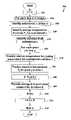
- the method 200initializes a time t to zero (step 202 ).
- the method 200enters a loop over each line n in the image to be printed (step 204 ).
- the method 200identifies the subinterval c of the current line n (step 206 ).
- the method 200may, for example, identify the subinterval c using the color tag preceding line n, assuming that there is a one-to-one correspondence between colors and subintervals ( FIG. 1C ).
- each of the subintervalsis associated with a possibly distinct energy computation function.
- the method 200identifies an energy computation function F c corresponding to the subinterval c (step 208 ). Examples of techniques that may be used to identify the energy computation function will be described below with respect to FIG. 2C .
- the method 200identifies the duration D of subinterval c (step 210 ).
- the duration of subinterval cmay differ from the duration of other subintervals in the same pixel-printing time.
- subinterval 106 ais shorter in duration than subinterval 106 b.
- the method 200enters a loop over each pixel j in line n (step 212 ).
- a thermal modelis provided for predicting the temperature of print head elements at the beginning of pixel-printing subintervals. Such a thermal model may, for example, be implemented in the manner described in the above-referenced patent applications.
- each pixel-printing subintervalis associated with a possibly distinct set of thermal model parameters.
- the method 200uses the thermal model parameters associated with subinterval c to predict the relative temperature T of the print head element that is to print pixel j at time t (step 214 ). Examples of techniques that may be used to perform step 214 are described below with respect to FIG. 2B .
- the thermal model described in the above-referenced patent applicationincludes a plurality of layers, each of which may be associated with one or more relative temperatures.
- step 214only refers to the finest-resolution layer in the thermal model, those having ordinary skill in the art will appreciate that generating the relative temperature predictions in step 214 will involve updating relative temperature predictions in other layers of the model.
- the method 200predicts the absolute temperature T h of the print head element that is to print pixel j at time t using the relative temperature T of the print head element (step 216 ).
- T arepresented the absolute temperature in patent application Ser. No. 09/934,703
- T hrepresented the absolute temperature in patent application Ser. No. 10/831,925.
- the print head element temperature prediction techniques disclosed in the above-referenced patent applicationsmay be modified to implement step 216 .
- the method 200computes the input energy E based on the print density d and the absolute print head element temperature T h (step 218 ). The method 200 provides the computed energy E to the appropriate print head element for the duration of the subinterval c (step 220 ).
- the method 200repeats steps 214 - 220 for the remaining pixels in the current line n (step 222 ).
- the method 200advances time t to the beginning of the next subinterval by adding D to t (step 224 ). For example, if the current value of t points to the beginning of subinterval 106 a , , then adding the duration of subinterval 106 a to t would cause t to point to the beginning of the next subinterval 106 b.
- the method 200repeats steps 206 - 224 for the remaining lines in the image to be printed (step 226 ).
- the method 200thereby performs thermal history control on the digital image.
- the method 200may take into account the unequal durations of the time steps 106 a - f when predicting the relative and absolute temperatures of print head elements. Additionally or alternatively, the method 200 may take into account the different thermal characteristics of the different color-forming layers of the print medium when selecting either or both of: (1) the thermal model parameters, and (2) the energy computation function.
- T (i) ( n,j )T (i) ( n ⁇ 1, j ) ⁇ i +A i E (i) ( n ⁇ 1, j ) Equation 1
- T (i) ( n,j )(1 ⁇ 2 k i ) T (i) ( n,j )+ k i ( T (i) ( n,j ⁇ 1)+ T (i) ( n,j+ 1)) Equation 2
- absolute temperatures T h of the print head elementsmay be predicted based on the relative temperatures T.
- the thermal modelincludes a plurality of layers.
- the notation T (i) (n,j)refers to the relative temperature at layer i and index j at the beginning of print head cycle n.
- T (0) (n,j)refers to the relative temperature of layer 0 , which has a one-to-one correspondence with the print head elements.
- Equation 1depends on two parameters, ⁇ i and A i , whose values depend on the size of the time step. Therefore, to apply Equation 1 to time steps of unequal duration, the values of these two parameters may be alternated from one time-step to the next, in sequence with the change of the step size. Likewise, Equation 2 depends on a parameter k i , that is also changed in sequence with the step size.
- Cbe the number of color-forming layers (and therefore also the number of subintervals). Distinct values of ⁇ i (c), A i (c), and k i (c) may be selected for 0 ⁇ c ⁇ C. Then, the relative print head element temperature T (0) (n,j) may be identified for each subinterval using the method shown in FIG. 2B , thereby implementing step 214 of method 200 ( FIG. 2A ). For subinterval c, values of ⁇ i (c) (step 230 ), A i (c) (step 232 ), and k i (c) (step 234 ) are identified.
- One way to accomplish this resultis to use the same parameter values for each subinterval in all layers of the thermal model other than layer 0 .
- the input energy to provide to the print headis computed using a different energy computation function for each color-forming layer (i.e., for each color).
- the energy computation functionmay compute the input energy based on a predicted head element temperature.
- the head element temperaturemay be computed using a head element temperature model that differs for each color-forming layer (i.e., for each color). For example, one or more parameters of the head temperature model may be modified for each of the color-forming layers.
- Equation 5E is the input energy, d is the desired density of the pixel to be printed, and T h is the (predicted or measured) absolute print head element temperature at the beginning of a subinterval.
- additional parametersmay be added to the energy computation function, such as the ambient printer temperature T r and the relative humidity RH to take such quantities into account when computing the input energy E.
- the ambient printer temperature T r and the relative humidity RHmay be added to the ambient printer temperature T r and the relative humidity RH to take such quantities into account when computing the input energy E.
- G(d)corresponds to the inverse gamma function at a specified reference temperature of zero
- S(d)is the sensitivity of the inverse gamma function to temperature variations away from the reference temperature at a fixed density.
- different G(d) and S(d) functionsare used to compute the input energy to be provided for each of the color-forming layers. For example, in a system which uses a print medium having three color-forming layers, three distinct G(d) and S(d) functions may be used.
- Such multiple functionsmay, for example, be represented by functions G c (d) and S c (d), for 0 ⁇ c ⁇ C.
- the energy computation function F cmay be identified using the method shown in FIG. 2C , thereby implementing step 208 of method 200 ( FIG. 2A ).
- functions G c (d) (step 252 ) and S c (d) (step 254 )are identified.
- the thermal history control algorithmmaintains a running estimate of the temperature profile of the thermal print head and applies the appropriate thermal corrections to the energies applied to the heaters while writing on each of the color-forming layers.
- the methodmay be used in conjunction with any number of color-forming layers, in which case there is a longer sequence of unequal time steps, with corresponding parameters ⁇ i , A i , and k i , for each size of time step, and functions G(d) and S(d) for each associated color-forming layer.
- Equation 7G′(d) and S′(d) are related to the functions G(d) and S(d).
- T mT r +A m ( T h ⁇ T r ) Equation 8
- T rrepresents the ambient temperature of the printer.
- a mis a constant derived from the printer line time and thermal characteristics of the media. As noted above, the thermal characteristics of the media and the subinterval duration may vary from subinterval to subinterval. Therefore, in one embodiment of the present invention, a different value of A m is used in each of the subintervals.
- a m (c)refers herein to the value of A m for subinterval c.
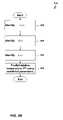
- FIG. 2Da flowchart is shown of a method 260 that is used in one embodiment of the present invention to compute the input energy E based on the current media temperature T m .
- the media temperature T mis computed for each pixel.
- the method 260begins after step 216 of the method 200 shown in FIG. 2A .
- the method 260identifies the ambient printer temperature T r , as described in the above-referenced patent applications (step 262 ).
- the method 260identifies the value of A m (c) that corresponds to subinterval c (step 264 ).
- the method 260identifies the media temperature T m based on the values of A m (c), T h , and T r , such as by using Equation 8 (step 266 ).
- the energy computation function F c for subinterval cwas previously identified in step 208 .
- the energy computation function F cmay be a function of density d and media temperature T m , rather than a function of density d and print head temperature T h as described above with respect to FIG. 2A .
- Such an energy computation functionmay, for example, have the form shown in Equation 7, in which case there may be distinct functions G′ c (d) and S′ c (d) for each subinterval c.
- the method 260computes the input energy E based on the density d and the media temperature T m using the identified energy computation function (step 270 ).
- the method 260then proceeds to step 220 of the method 200 shown in FIG. 2A .
- the ambient printer temperature T rwill typically have a long time constant and therefore may not be expected to change significantly during a single print job.
- FIG. 2Ea flowchart is shown of a method 272 for applying the precomputation techniques disclosed in the above-referenced patent application to the method 200 shown in FIG. 2A .
- the method 272identifies the ambient temperature T r (step 262 ), as described above with respect to FIG. 2D .
- the method 272precomputes the functions G( ⁇ ) and S( ⁇ ) for all values of c using the identified value of T r (step 276 ).
- the method 272then performs steps 202 , 204 , and 206 , as described above with respect to the method 200 of FIG. 2A .
- the method 272then identifies the energy computation function F c for subinterval c based on the precomputed functions G( ⁇ ) and S( ⁇ ) (step 278 ). Having identified these functions, the method 272 performs steps 210 - 226 (from method 200 of FIG. 2A ) using the identified function F c .
- Equation 12The corrected thermistor temperature T′ s is then used to perform thermal history control.
- ⁇ T rT r ⁇ T rc (the difference between the current ambient printer temperature and the ambient printer temperature at which the thermal history control algorithm was calibrated).
- the correction factor f tis given by Equation 12:
- the correction factor f t shown in Equation 11 and Equation 12is valid only for a particular color (i.e., for a particular value of c) corresponding to the value of A m . Attempts to apply such a correction factor to other colors will produce suboptimal results.
- the use of the correction factor f tis modified to apply to a printer that prints sequentially on multiple color-forming layers in a single pass.
- f tmay be made an express function of c, by using the subinterval-dependent values of A m (c), as shown in Equation 13:
- ⁇ (c)may then be selected and used in Equation 16 for each subinterval when performing thermal history control.
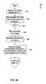
- FIG. 2Fa flowchart is shown of a method 280 for modifying the method 200 of FIG. 2A in the manner just described.
- the method 280identifies the ambient temperature T r (step 262 ) in the manner described above with respect to FIG. 2D .
- the method 280calculates ⁇ (c) for all values of c using Equation 15 (step 286 ).
- the method 280performs steps 202 - 216 as described above with respect to FIG. 2A .
- the method 280identifies the modified absolute temperature T′ h using Equation 16 (step 288 ).
- the method 280computes the input energy E based on the print density d and the modified print head element temperature T′ h (step 290 ).
- the method 280performs steps 220 - 226 as described above with respect to FIG. 2A .
- the techniques disclosed hereinhave a variety of advantages.
- the techniques disclosed hereinmay be applied to perform thermal history control in a thermal printer in which a single thermal print head prints sequentially on multiple color-forming layers in a single pass.
- the techniques disclosed hereinenable the thermal history control to be optimized for each of the color-forming layers, thereby improving the quality of printed output.
- the techniques disclosed hereinmay be used to model the thermal response of the output medium during printing subintervals of unequal duration.
- the thermal history control algorithmmay be used in conjunction with printers having such unequal subintervals, thereby improving the quality of printed output.
- Such use of varying energy computation functions and thermal model parametersmay be used in combination, thereby optimizing the thermal history control algorithm for use with thermal printers in which a single thermal print head prints sequentially on multiple color-forming layers in a single pass using pixel-printing subintervals of unequal duration.
- the techniques disclosed hereinhave the advantages disclosed in the above-referenced patent applications.
- the techniques disclosed hereinreduce or eliminate the problem of “density drift” by taking the current ambient temperature of the print head and the thermal and energy histories of the print head into account when computing the energy to be provided to the print head elements, thereby raising the temperatures of the print head elements only to the temperatures necessary to produce the desired densities.
- a further advantage of various embodiments of the present inventionis that they may either increase or decrease the input energy provided to the print head elements, as may be necessary or desirable to produce the desired densities.
- the techniques described abovemay be implemented, for example, in hardware, software, firmware, or any combination thereof.
- the techniques described abovemay be implemented in one or more computer programs executing on a programmable computer and/or printer including a processor, a storage medium readable by the processor (including, for example, volatile and non-volatile memory and/or storage elements), at least one input device, and at least one output device.
- Program codemay be applied to data entered using the input device to perform the functions described herein and to generate output information.
- the output informationmay be applied to one or more output devices.
- Printers suitable for use with various embodiments of the present inventiontypically include a print engine and a printer controller.
- the printer controllermay, for example, receive print data from a host computer and generates page information to be printed based on the print data.
- the printer controllertransmits the page information to the print engine to be printed.
- the print engineperforms the physical printing of the image specified by the page information on the output medium.
- Each computer program within the scope of the claims belowmay be implemented in any programming language, such as assembly language, machine language, a high-level procedural programming language, or an object-oriented programming language.
- the programming languagemay be a compiled or interpreted programming language.
- Each computer programmay be implemented in a computer program product tangibly embodied in a machine-readable storage device for execution by a computer processor. Method steps of the invention may be performed by a computer processor executing a program tangibly embodied on a computer-readable medium to perform functions of the invention by operating on input and generating output.
Landscapes
- Engineering & Computer Science (AREA)
- Theoretical Computer Science (AREA)
- Physics & Mathematics (AREA)
- General Engineering & Computer Science (AREA)
- General Physics & Mathematics (AREA)
- Human Computer Interaction (AREA)
- Quality & Reliability (AREA)
- Electronic Switches (AREA)
Abstract
Description
T(i)(n,j)=T(i)(n−1,j)αi+AiE(i)(n−1,j) Equation 1
T(i)(n,j)=(1−2ki)T(i)(n,j)+ki(T(i)(n,j−1)+T(i)(n,j+1)) Equation 2
T(i)(n,j)=T(i)(n−1,j)αi(c)+Ai(c)E(i)(n−1,j) Equation 3
T(i)(n,j)=(1−2ki(c))T(i)(n,j)+ki(c)(T(i)(n,j−1)+T(i)(n,j+1)) Equation 4
E=F(d,Th) Equation 5
E=G(d)+S(d)Th Equation 6
E=G′(d)+S′(d)Tm Equation 7
Tm=Tr+Am(Th−Tr) Equation 8
G(d,Tr)=G′(d)+S′(d)(1−Am(c))Tr Equation 9
S(d)=S′(d)Am(c) Equation 10
T′s=Ts+ftΔTr Equation 11
T′s=Ts+ft(c0)ΔTr Equation 14
δ(c)=(ft(c)−ft(c0))ΔTr Equation 15
T′h=Th+δ(c) Equation 16
Claims (28)
Priority Applications (8)
| Application Number | Priority Date | Filing Date | Title |
|---|---|---|---|
| US10/910,880US7298387B2 (en) | 2001-08-22 | 2004-08-04 | Thermal response correction system |
| PCT/US2005/026106WO2006020352A1 (en) | 2004-08-04 | 2005-07-22 | Thermal response correction system |
| JP2007524837AJP2008508128A (en) | 2004-08-04 | 2005-07-22 | Thermal response correction system |
| KR1020077002779AKR100873598B1 (en) | 2004-08-04 | 2005-07-22 | Thermal response correction system |
| EP05775379AEP1773595A1 (en) | 2004-08-04 | 2005-07-22 | Thermal response correction system |
| CN2005800333418ACN101031429B (en) | 2004-08-04 | 2005-07-22 | Thermal response correction system |
| CA002575126ACA2575126C (en) | 2004-08-04 | 2005-07-22 | Thermal response correction system |
| JP2010152741AJP2010247542A (en) | 2004-08-04 | 2010-07-05 | Thermal response correction system |
Applications Claiming Priority (3)
| Application Number | Priority Date | Filing Date | Title |
|---|---|---|---|
| US09/934,703US6819347B2 (en) | 2001-08-22 | 2001-08-22 | Thermal response correction system |
| US10/831,925US7295224B2 (en) | 2001-08-22 | 2004-04-26 | Thermal response correction system |
| US10/910,880US7298387B2 (en) | 2001-08-22 | 2004-08-04 | Thermal response correction system |
Related Parent Applications (1)
| Application Number | Title | Priority Date | Filing Date |
|---|---|---|---|
| US10/831,925Continuation-In-PartUS7295224B2 (en) | 2001-08-22 | 2004-04-26 | Thermal response correction system |
Publications (2)
| Publication Number | Publication Date |
|---|---|
| US20050007438A1 US20050007438A1 (en) | 2005-01-13 |
| US7298387B2true US7298387B2 (en) | 2007-11-20 |
Family
ID=35311530
Family Applications (1)
| Application Number | Title | Priority Date | Filing Date |
|---|---|---|---|
| US10/910,880Expired - Fee RelatedUS7298387B2 (en) | 2001-08-22 | 2004-08-04 | Thermal response correction system |
Country Status (7)
| Country | Link |
|---|---|
| US (1) | US7298387B2 (en) |
| EP (1) | EP1773595A1 (en) |
| JP (2) | JP2008508128A (en) |
| KR (1) | KR100873598B1 (en) |
| CN (1) | CN101031429B (en) |
| CA (1) | CA2575126C (en) |
| WO (1) | WO2006020352A1 (en) |
Cited By (10)
| Publication number | Priority date | Publication date | Assignee | Title |
|---|---|---|---|---|
| US20060159502A1 (en)* | 2005-01-14 | 2006-07-20 | Saquib Suhail S | Printer thermal response calibration system |
| US20060290769A1 (en)* | 2005-06-23 | 2006-12-28 | Polaroid Corporation | Print head pulsing techniques for multicolor printers |
| US20080040066A1 (en)* | 2001-08-22 | 2008-02-14 | Polaroid Corporation | Thermal response correction system |
| US20080225308A1 (en)* | 2003-02-25 | 2008-09-18 | Zink Imaging, Llc | Image stitching for a multi-head printer |
| US20080238967A1 (en)* | 2001-05-30 | 2008-10-02 | Zink Imaging, Llc | Print head pulsing techniques for multicolor printers |
| US20080316291A1 (en)* | 2005-06-28 | 2008-12-25 | Zink Imaging, Llc | Parametric programmable thermal printer |
| US20090309946A1 (en)* | 2008-06-13 | 2009-12-17 | Saquib Suhail S | Thermal Response Correction System for Multicolor Printing |
| US8377844B2 (en) | 2001-05-30 | 2013-02-19 | Zink Imaging, Inc. | Thermally-insulating layers and direct thermal imaging members containing same |
| US10953664B2 (en)* | 2018-07-13 | 2021-03-23 | Canon Kabushiki Kaisha | Printing apparatus, printing method, and storage medium |
| US20220203743A1 (en)* | 2020-12-28 | 2022-06-30 | Brother Kogyo Kabushiki Kaisha | Printing device creating print data differentiated in color development state depending on viewing direction of multi-layer medium |
Families Citing this family (20)
| Publication number | Priority date | Publication date | Assignee | Title |
|---|---|---|---|---|
| WO2002096665A1 (en)* | 2001-05-30 | 2002-12-05 | Polaroid Corporation | Thermal imaging system |
| WO2007035803A2 (en)* | 2005-09-20 | 2007-03-29 | Zink Imaging, Llc | Thermal print head temperature estimation system |
| JP4905414B2 (en)* | 2008-06-04 | 2012-03-28 | セイコーエプソン株式会社 | Liquid material discharge apparatus, liquid material discharge method, and electro-optical device manufacturing method |
| US20210133871A1 (en) | 2014-05-20 | 2021-05-06 | State Farm Mutual Automobile Insurance Company | Autonomous vehicle operation feature usage recommendations |
| US10373259B1 (en) | 2014-05-20 | 2019-08-06 | State Farm Mutual Automobile Insurance Company | Fully autonomous vehicle insurance pricing |
| US9972054B1 (en) | 2014-05-20 | 2018-05-15 | State Farm Mutual Automobile Insurance Company | Accident fault determination for autonomous vehicles |
| US11669090B2 (en) | 2014-05-20 | 2023-06-06 | State Farm Mutual Automobile Insurance Company | Autonomous vehicle operation feature monitoring and evaluation of effectiveness |
| US10599155B1 (en) | 2014-05-20 | 2020-03-24 | State Farm Mutual Automobile Insurance Company | Autonomous vehicle operation feature monitoring and evaluation of effectiveness |
| US10387962B1 (en) | 2014-07-21 | 2019-08-20 | State Farm Mutual Automobile Insurance Company | Methods of reconstructing an accident scene using telematics data |
| US10157423B1 (en) | 2014-11-13 | 2018-12-18 | State Farm Mutual Automobile Insurance Company | Autonomous vehicle operating style and mode monitoring |
| US9805601B1 (en) | 2015-08-28 | 2017-10-31 | State Farm Mutual Automobile Insurance Company | Vehicular traffic alerts for avoidance of abnormal traffic conditions |
| US10134278B1 (en) | 2016-01-22 | 2018-11-20 | State Farm Mutual Automobile Insurance Company | Autonomous vehicle application |
| US10324463B1 (en) | 2016-01-22 | 2019-06-18 | State Farm Mutual Automobile Insurance Company | Autonomous vehicle operation adjustment based upon route |
| US10493936B1 (en) | 2016-01-22 | 2019-12-03 | State Farm Mutual Automobile Insurance Company | Detecting and responding to autonomous vehicle collisions |
| US11719545B2 (en) | 2016-01-22 | 2023-08-08 | Hyundai Motor Company | Autonomous vehicle component damage and salvage assessment |
| US11242051B1 (en) | 2016-01-22 | 2022-02-08 | State Farm Mutual Automobile Insurance Company | Autonomous vehicle action communications |
| US10395332B1 (en) | 2016-01-22 | 2019-08-27 | State Farm Mutual Automobile Insurance Company | Coordinated autonomous vehicle automatic area scanning |
| US11441916B1 (en) | 2016-01-22 | 2022-09-13 | State Farm Mutual Automobile Insurance Company | Autonomous vehicle trip routing |
| EP3336682A1 (en)* | 2016-12-14 | 2018-06-20 | Siegwerk Druckfarben AG & Co. KGaA | Printing method |
| US20220281229A1 (en)* | 2019-10-11 | 2022-09-08 | Hewlett-Packard Development Company, L.P. | Thermal printers storing color correction data |
Citations (47)
| Publication number | Priority date | Publication date | Assignee | Title |
|---|---|---|---|---|
| US4070587A (en) | 1975-02-14 | 1978-01-24 | Canon Kabushiki Kaisha | Energizing control system for an intermittently energized device |
| US4284876A (en) | 1979-04-24 | 1981-08-18 | Oki Electric Industry Co., Ltd. | Thermal printing system |
| US4309712A (en) | 1978-12-27 | 1982-01-05 | Canon Kabushiki Kaisha | Thermal printer |
| US4347518A (en) | 1979-09-04 | 1982-08-31 | Gould Inc. | Thermal array protection apparatus |
| US4364063A (en) | 1980-03-31 | 1982-12-14 | Tokyo Shibaura Denki Kabushiki Kaisha | Thermal recording apparatus |
| US4391535A (en) | 1981-08-10 | 1983-07-05 | Intermec Corporation | Method and apparatus for controlling the area of a thermal print medium that is exposed by a thermal printer |
| JPS58164368A (en) | 1982-03-25 | 1983-09-29 | Ricoh Co Ltd | Thermal head halftone recording device |
| US4415908A (en) | 1980-06-13 | 1983-11-15 | Canon Kabushiki Kaisha | Thermal printer |
| US4443121A (en) | 1982-03-02 | 1984-04-17 | Sony Corporation | Thermal printing apparatus with reference gray scale comparator |
| EP0110675A2 (en) | 1982-11-29 | 1984-06-13 | Kabushiki Kaisha Toshiba | Thermal recording system |
| JPS59127781A (en) | 1983-01-11 | 1984-07-23 | Fuji Xerox Co Ltd | Driving circuit for thermal head |
| US4464669A (en) | 1981-06-19 | 1984-08-07 | Tokyo Shibaura Denki Kabushiki Kaisha | Thermal printer |
| US4514738A (en) | 1982-11-22 | 1985-04-30 | Tokyo Shibaura Denki Kabushiki Kaisha | Thermal recording system |
| US4524368A (en) | 1983-04-01 | 1985-06-18 | Fuji Xerox Co., Ltd. | Thermal head drive circuit |
| US4563691A (en) | 1984-12-24 | 1986-01-07 | Fuji Xerox Co., Ltd. | Thermo-sensitive recording apparatus |
| US4688051A (en) | 1983-08-15 | 1987-08-18 | Ricoh Company, Ltd. | Thermal print head driving system |
| JPH02248264A (en) | 1989-03-20 | 1990-10-04 | Fujitsu Ltd | Thermal recording device with temperature prediction constant adjustment function |
| JPH02289364A (en) | 1989-04-28 | 1990-11-29 | Victor Co Of Japan Ltd | Thermal head heat accumulation correction circuit |
| JPH0324972A (en) | 1989-06-23 | 1991-02-01 | Fujitsu Ltd | Thermal head heat storage prediction device |
| US5006866A (en) | 1988-10-31 | 1991-04-09 | Kabushiki Kaisha Toshiba | Thermal printing apparatus responsive to estimated stored heat of the heating element |
| US5066961A (en) | 1989-02-17 | 1991-11-19 | Matsushita Electric Industrial Co., Ltd. | Tonal printer utilizing heat prediction and temperature detection means |
| US5086306A (en) | 1989-07-19 | 1992-02-04 | Ricoh Company, Ltd. | Line head driving apparatus |
| US5115252A (en) | 1989-02-03 | 1992-05-19 | Eiichi Sasaki | Thermal head drive apparatus correcting for the influence on a printing element of heat from other printing elements |
| US5132709A (en) | 1991-08-26 | 1992-07-21 | Zebra Technologies Corporation | Apparatus and method for closed-loop, thermal control of printing head |
| US5132703A (en) | 1991-03-08 | 1992-07-21 | Yokogawa Electric Corporation | Thermal history control in a recorder using a line thermal head |
| US5162813A (en) | 1989-08-31 | 1992-11-10 | Fuji Photo Film Co., Ltd. | Method of and device for driving thermal head in printer |
| US5184150A (en) | 1989-08-07 | 1993-02-02 | Sharp Kabushiki Kaisha | Thermal printer for providing printed characters with a uniform density |
| US5248995A (en) | 1991-02-25 | 1993-09-28 | Alps Electric Co., Ltd. | Heat control method of a thermal head |
| US5268706A (en) | 1991-02-14 | 1993-12-07 | Alps Electric Co., Ltd. | Actuating control method of thermal head |
| US5422662A (en) | 1992-03-27 | 1995-06-06 | Nec Corporation | Thermal printer head having current sensors connected to heating elements |
| US5539443A (en) | 1992-07-03 | 1996-07-23 | Matsushita Electric Industrial Co., Ltd. | Printer utilizing temperature evaluation and temperature detection |
| US5576745A (en) | 1993-05-27 | 1996-11-19 | Canon Kabushiki Kaisha | Recording apparatus having thermal head and recording method |
| US5623297A (en) | 1993-07-07 | 1997-04-22 | Intermec Corporation | Method and apparatus for controlling a thermal printhead |
| US5625399A (en) | 1992-01-31 | 1997-04-29 | Intermec Corporation | Method and apparatus for controlling a thermal printhead |
| US5642148A (en) | 1993-11-30 | 1997-06-24 | Nec Corporation | Thermal head apparatus with integrated circuits and current detection |
| US5644351A (en) | 1992-12-04 | 1997-07-01 | Matsushita Electric Industrial Co., Ltd. | Thermal gradation printing apparatus |
| US5646672A (en) | 1994-12-16 | 1997-07-08 | Nec Corporation | Thermal head apparatus |
| EP0790131A1 (en) | 1996-02-13 | 1997-08-20 | Fuji Photo Film Co., Ltd. | Apparatus and method for thermal image recording |
| US5706044A (en) | 1994-12-20 | 1998-01-06 | Nec Corporation | Thermal head apparatus |
| US5719615A (en) | 1989-03-09 | 1998-02-17 | Kyocera Corporation | Apparatus for driving heating elements of a thermal head |
| US5800075A (en) | 1996-04-11 | 1998-09-01 | Fuji Photo Film Co., Ltd. | Data processing method for eliminating influence of heat accumulating in thermal head |
| US5841461A (en) | 1995-08-17 | 1998-11-24 | Fuji Photo Film Co., Ltd. | Accumulated heat correction method and apparatus |
| US5889546A (en) | 1996-06-04 | 1999-03-30 | Shinko Electric Co., Ltd. | Heat accumulation control device for line-type thermoelectric printer |
| US6186683B1 (en) | 1997-08-11 | 2001-02-13 | Minolta Co., Ltd. | Recording apparatus |
| US20030043251A1 (en) | 2001-08-22 | 2003-03-06 | Saquib Suhail S. | Thermal response correction system |
| US6537410B2 (en) | 2000-02-01 | 2003-03-25 | Polaroid Corporation | Thermal transfer recording system |
| US20030125206A1 (en) | 2001-05-30 | 2003-07-03 | Bhatt Jayprakash C. | Thermal imaging system |
Family Cites Families (1)
| Publication number | Priority date | Publication date | Assignee | Title |
|---|---|---|---|---|
| US4309876A (en)* | 1979-10-22 | 1982-01-12 | Carrier Corporation | Method and apparatus for satisfying heating and cooling demands and control therefor |
- 2004
- 2004-08-04USUS10/910,880patent/US7298387B2/ennot_activeExpired - Fee Related
- 2005
- 2005-07-22EPEP05775379Apatent/EP1773595A1/ennot_activeWithdrawn
- 2005-07-22CNCN2005800333418Apatent/CN101031429B/ennot_activeExpired - Fee Related
- 2005-07-22JPJP2007524837Apatent/JP2008508128A/enactivePending
- 2005-07-22CACA002575126Apatent/CA2575126C/ennot_activeExpired - Fee Related
- 2005-07-22KRKR1020077002779Apatent/KR100873598B1/ennot_activeExpired - Fee Related
- 2005-07-22WOPCT/US2005/026106patent/WO2006020352A1/enactiveApplication Filing
- 2010
- 2010-07-05JPJP2010152741Apatent/JP2010247542A/enactivePending
Patent Citations (50)
| Publication number | Priority date | Publication date | Assignee | Title |
|---|---|---|---|---|
| US4070587A (en) | 1975-02-14 | 1978-01-24 | Canon Kabushiki Kaisha | Energizing control system for an intermittently energized device |
| US4309712A (en) | 1978-12-27 | 1982-01-05 | Canon Kabushiki Kaisha | Thermal printer |
| US4284876A (en) | 1979-04-24 | 1981-08-18 | Oki Electric Industry Co., Ltd. | Thermal printing system |
| US4347518A (en) | 1979-09-04 | 1982-08-31 | Gould Inc. | Thermal array protection apparatus |
| US4364063A (en) | 1980-03-31 | 1982-12-14 | Tokyo Shibaura Denki Kabushiki Kaisha | Thermal recording apparatus |
| US4415908A (en) | 1980-06-13 | 1983-11-15 | Canon Kabushiki Kaisha | Thermal printer |
| US4464669A (en) | 1981-06-19 | 1984-08-07 | Tokyo Shibaura Denki Kabushiki Kaisha | Thermal printer |
| US4391535A (en) | 1981-08-10 | 1983-07-05 | Intermec Corporation | Method and apparatus for controlling the area of a thermal print medium that is exposed by a thermal printer |
| US4443121A (en) | 1982-03-02 | 1984-04-17 | Sony Corporation | Thermal printing apparatus with reference gray scale comparator |
| JPS58164368A (en) | 1982-03-25 | 1983-09-29 | Ricoh Co Ltd | Thermal head halftone recording device |
| US4514738A (en) | 1982-11-22 | 1985-04-30 | Tokyo Shibaura Denki Kabushiki Kaisha | Thermal recording system |
| EP0110675A2 (en) | 1982-11-29 | 1984-06-13 | Kabushiki Kaisha Toshiba | Thermal recording system |
| JPS59127781A (en) | 1983-01-11 | 1984-07-23 | Fuji Xerox Co Ltd | Driving circuit for thermal head |
| US4607262A (en) | 1983-01-11 | 1986-08-19 | Fuji Xerox Co., Ltd. | Thermal head drive circuit |
| US4524368A (en) | 1983-04-01 | 1985-06-18 | Fuji Xerox Co., Ltd. | Thermal head drive circuit |
| US4688051A (en) | 1983-08-15 | 1987-08-18 | Ricoh Company, Ltd. | Thermal print head driving system |
| US4563691A (en) | 1984-12-24 | 1986-01-07 | Fuji Xerox Co., Ltd. | Thermo-sensitive recording apparatus |
| US5006866A (en) | 1988-10-31 | 1991-04-09 | Kabushiki Kaisha Toshiba | Thermal printing apparatus responsive to estimated stored heat of the heating element |
| US5115252A (en) | 1989-02-03 | 1992-05-19 | Eiichi Sasaki | Thermal head drive apparatus correcting for the influence on a printing element of heat from other printing elements |
| US5066961A (en) | 1989-02-17 | 1991-11-19 | Matsushita Electric Industrial Co., Ltd. | Tonal printer utilizing heat prediction and temperature detection means |
| US5719615A (en) | 1989-03-09 | 1998-02-17 | Kyocera Corporation | Apparatus for driving heating elements of a thermal head |
| JPH02248264A (en) | 1989-03-20 | 1990-10-04 | Fujitsu Ltd | Thermal recording device with temperature prediction constant adjustment function |
| JPH02289364A (en) | 1989-04-28 | 1990-11-29 | Victor Co Of Japan Ltd | Thermal head heat accumulation correction circuit |
| JPH0324972A (en) | 1989-06-23 | 1991-02-01 | Fujitsu Ltd | Thermal head heat storage prediction device |
| US5086306A (en) | 1989-07-19 | 1992-02-04 | Ricoh Company, Ltd. | Line head driving apparatus |
| US5184150A (en) | 1989-08-07 | 1993-02-02 | Sharp Kabushiki Kaisha | Thermal printer for providing printed characters with a uniform density |
| US5162813A (en) | 1989-08-31 | 1992-11-10 | Fuji Photo Film Co., Ltd. | Method of and device for driving thermal head in printer |
| US5268706A (en) | 1991-02-14 | 1993-12-07 | Alps Electric Co., Ltd. | Actuating control method of thermal head |
| US5248995A (en) | 1991-02-25 | 1993-09-28 | Alps Electric Co., Ltd. | Heat control method of a thermal head |
| US5132703A (en) | 1991-03-08 | 1992-07-21 | Yokogawa Electric Corporation | Thermal history control in a recorder using a line thermal head |
| US5132709A (en) | 1991-08-26 | 1992-07-21 | Zebra Technologies Corporation | Apparatus and method for closed-loop, thermal control of printing head |
| US5625399A (en) | 1992-01-31 | 1997-04-29 | Intermec Corporation | Method and apparatus for controlling a thermal printhead |
| US5422662A (en) | 1992-03-27 | 1995-06-06 | Nec Corporation | Thermal printer head having current sensors connected to heating elements |
| US5539443A (en) | 1992-07-03 | 1996-07-23 | Matsushita Electric Industrial Co., Ltd. | Printer utilizing temperature evaluation and temperature detection |
| US5644351A (en) | 1992-12-04 | 1997-07-01 | Matsushita Electric Industrial Co., Ltd. | Thermal gradation printing apparatus |
| US5808653A (en) | 1992-12-04 | 1998-09-15 | Matsushita Electric Industrial Co., Ltd. | Thermal gradation printing apparatus |
| US5576745A (en) | 1993-05-27 | 1996-11-19 | Canon Kabushiki Kaisha | Recording apparatus having thermal head and recording method |
| US5623297A (en) | 1993-07-07 | 1997-04-22 | Intermec Corporation | Method and apparatus for controlling a thermal printhead |
| US5642148A (en) | 1993-11-30 | 1997-06-24 | Nec Corporation | Thermal head apparatus with integrated circuits and current detection |
| US5646672A (en) | 1994-12-16 | 1997-07-08 | Nec Corporation | Thermal head apparatus |
| US5706044A (en) | 1994-12-20 | 1998-01-06 | Nec Corporation | Thermal head apparatus |
| US5841461A (en) | 1995-08-17 | 1998-11-24 | Fuji Photo Film Co., Ltd. | Accumulated heat correction method and apparatus |
| EP0790131A1 (en) | 1996-02-13 | 1997-08-20 | Fuji Photo Film Co., Ltd. | Apparatus and method for thermal image recording |
| US5999204A (en) | 1996-02-13 | 1999-12-07 | Fuji Photo Film Co., Ltd. | Apparatus and method for thermal image recording |
| US5800075A (en) | 1996-04-11 | 1998-09-01 | Fuji Photo Film Co., Ltd. | Data processing method for eliminating influence of heat accumulating in thermal head |
| US5889546A (en) | 1996-06-04 | 1999-03-30 | Shinko Electric Co., Ltd. | Heat accumulation control device for line-type thermoelectric printer |
| US6186683B1 (en) | 1997-08-11 | 2001-02-13 | Minolta Co., Ltd. | Recording apparatus |
| US6537410B2 (en) | 2000-02-01 | 2003-03-25 | Polaroid Corporation | Thermal transfer recording system |
| US20030125206A1 (en) | 2001-05-30 | 2003-07-03 | Bhatt Jayprakash C. | Thermal imaging system |
| US20030043251A1 (en) | 2001-08-22 | 2003-03-06 | Saquib Suhail S. | Thermal response correction system |
Cited By (22)
| Publication number | Priority date | Publication date | Assignee | Title |
|---|---|---|---|---|
| US8377844B2 (en) | 2001-05-30 | 2013-02-19 | Zink Imaging, Inc. | Thermally-insulating layers and direct thermal imaging members containing same |
| US20080238967A1 (en)* | 2001-05-30 | 2008-10-02 | Zink Imaging, Llc | Print head pulsing techniques for multicolor printers |
| US7791626B2 (en) | 2001-05-30 | 2010-09-07 | Zink Imaging, Inc. | Print head pulsing techniques for multicolor printers |
| US8098269B2 (en) | 2001-05-30 | 2012-01-17 | Zink Imaging, Inc. | Print head pulsing techniques for multicolor printers |
| US20080040066A1 (en)* | 2001-08-22 | 2008-02-14 | Polaroid Corporation | Thermal response correction system |
| US7825943B2 (en)* | 2001-08-22 | 2010-11-02 | Mitcham Global Investments Ltd. | Thermal response correction system |
| US8072644B2 (en) | 2003-02-25 | 2011-12-06 | Zink Imaging, Inc. | Image stitching for a multi-head printer |
| US20080225308A1 (en)* | 2003-02-25 | 2008-09-18 | Zink Imaging, Llc | Image stitching for a multi-head printer |
| US8345307B2 (en) | 2003-02-25 | 2013-01-01 | Zink Imaging, Inc. | Image stitching for a multi-head printer |
| US7808674B2 (en) | 2003-02-25 | 2010-10-05 | Zink Imaging, Inc. | Image stitching for a multi-head printer |
| US7545402B2 (en)* | 2005-01-14 | 2009-06-09 | Polaroid Corporation | Printer thermal response calibration system |
| US20060159502A1 (en)* | 2005-01-14 | 2006-07-20 | Saquib Suhail S | Printer thermal response calibration system |
| US8164609B2 (en) | 2005-06-23 | 2012-04-24 | Zink Imaging, Inc. | Print head pulsing techniques for multicolor printers |
| US7830405B2 (en) | 2005-06-23 | 2010-11-09 | Zink Imaging, Inc. | Print head pulsing techniques for multicolor printers |
| US20060290769A1 (en)* | 2005-06-23 | 2006-12-28 | Polaroid Corporation | Print head pulsing techniques for multicolor printers |
| US8502846B2 (en) | 2005-06-23 | 2013-08-06 | Zink Imaging, Inc. | Print head pulsing techniques for multicolor printers |
| US20080316291A1 (en)* | 2005-06-28 | 2008-12-25 | Zink Imaging, Llc | Parametric programmable thermal printer |
| US8009184B2 (en) | 2008-06-13 | 2011-08-30 | Zink Imaging, Inc. | Thermal response correction system for multicolor printing |
| US20090309946A1 (en)* | 2008-06-13 | 2009-12-17 | Saquib Suhail S | Thermal Response Correction System for Multicolor Printing |
| US10953664B2 (en)* | 2018-07-13 | 2021-03-23 | Canon Kabushiki Kaisha | Printing apparatus, printing method, and storage medium |
| US20220203743A1 (en)* | 2020-12-28 | 2022-06-30 | Brother Kogyo Kabushiki Kaisha | Printing device creating print data differentiated in color development state depending on viewing direction of multi-layer medium |
| US11654707B2 (en)* | 2020-12-28 | 2023-05-23 | Brother Kogyo Kabushiki Kaisha | Printing device creating print data differentiated in color development state depending on viewing direction of multi-layer medium |
Also Published As
| Publication number | Publication date |
|---|---|
| CN101031429A (en) | 2007-09-05 |
| WO2006020352A1 (en) | 2006-02-23 |
| KR20070055495A (en) | 2007-05-30 |
| EP1773595A1 (en) | 2007-04-18 |
| JP2008508128A (en) | 2008-03-21 |
| US20050007438A1 (en) | 2005-01-13 |
| KR100873598B1 (en) | 2008-12-11 |
| CN101031429B (en) | 2011-12-14 |
| JP2010247542A (en) | 2010-11-04 |
| CA2575126A1 (en) | 2006-02-23 |
| CA2575126C (en) | 2009-11-03 |
Similar Documents
| Publication | Publication Date | Title |
|---|---|---|
| US7298387B2 (en) | Thermal response correction system | |
| US7825943B2 (en) | Thermal response correction system | |
| EP2296902B1 (en) | Thermal response correction system for multicolor printing | |
| US6819347B2 (en) | Thermal response correction system | |
| JP2010023520A (en) | Thermal response correction system |
Legal Events
| Date | Code | Title | Description |
|---|---|---|---|
| AS | Assignment | Owner name:POLAROID CORPORATION, MASSACHUSETTS Free format text:ASSIGNMENT OF ASSIGNORS INTEREST;ASSIGNORS:BUSCH, BRIAN D.;SAQUIB, SUHAIL S.;VETTERLING, WILLIAM T.;REEL/FRAME:015665/0116 Effective date:20040804 | |
| AS | Assignment | Owner name:WILMINGTON TRUST COMPANY, AS COLLATERAL AGENT,DELA Free format text:SECURITY AGREEMENT;ASSIGNORS:POLAROLD HOLDING COMPANY;POLAROID CORPORATION;POLAROID ASIA PACIFIC LLC;AND OTHERS;REEL/FRAME:016602/0332 Effective date:20050428 Owner name:JPMORGAN CHASE BANK,N.A,AS ADMINISTRATIVE AGENT,WI Free format text:SECURITY INTEREST;ASSIGNORS:POLAROID HOLDING COMPANY;POLAROID CORPORATION;POLAROID ASIA PACIFIC LLC;AND OTHERS;REEL/FRAME:016602/0603 Effective date:20050428 Owner name:WILMINGTON TRUST COMPANY, AS COLLATERAL AGENT, DEL Free format text:SECURITY AGREEMENT;ASSIGNORS:POLAROLD HOLDING COMPANY;POLAROID CORPORATION;POLAROID ASIA PACIFIC LLC;AND OTHERS;REEL/FRAME:016602/0332 Effective date:20050428 Owner name:WILMINGTON TRUST COMPANY, AS COLLATERAL AGENT, DEL Free format text:ASSIGNMENT OF ASSIGNORS INTEREST;ASSIGNORS:POLAROLD HOLDING COMPANY;POLAROID CORPORATION;POLAROID ASIA PACIFIC LLC;AND OTHERS;REEL/FRAME:016602/0332 Effective date:20050428 Owner name:JPMORGAN CHASE BANK,N.A,AS ADMINISTRATIVE AGENT, W Free format text:SECURITY INTEREST;ASSIGNORS:POLAROID HOLDING COMPANY;POLAROID CORPORATION;POLAROID ASIA PACIFIC LLC;AND OTHERS;REEL/FRAME:016602/0603 Effective date:20050428 | |
| AS | Assignment | Owner name:POLAROID HOLDING COMPANY, MASSACHUSETTS Free format text:RELEASE OF SECURITY INTEREST IN PATENTS;ASSIGNOR:WILMINGTON TRUST COMPANY;REEL/FRAME:019699/0512 Effective date:20070425 Owner name:POLAROID CORPORATION, MASSACHUSETTS Free format text:RELEASE OF SECURITY INTEREST IN PATENTS;ASSIGNOR:WILMINGTON TRUST COMPANY;REEL/FRAME:019699/0512 Effective date:20070425 Owner name:POLAROID CAPITAL LLC, MASSACHUSETTS Free format text:RELEASE OF SECURITY INTEREST IN PATENTS;ASSIGNOR:WILMINGTON TRUST COMPANY;REEL/FRAME:019699/0512 Effective date:20070425 Owner name:POLAROID ASIA PACIFIC LLC, MASSACHUSETTS Free format text:RELEASE OF SECURITY INTEREST IN PATENTS;ASSIGNOR:WILMINGTON TRUST COMPANY;REEL/FRAME:019699/0512 Effective date:20070425 Owner name:POLAROID EYEWEAR LLC, MASSACHUSETTS Free format text:RELEASE OF SECURITY INTEREST IN PATENTS;ASSIGNOR:WILMINGTON TRUST COMPANY;REEL/FRAME:019699/0512 Effective date:20070425 Owner name:POLOROID INTERNATIONAL HOLDING LLC, MASSACHUSETTS Free format text:RELEASE OF SECURITY INTEREST IN PATENTS;ASSIGNOR:WILMINGTON TRUST COMPANY;REEL/FRAME:019699/0512 Effective date:20070425 Owner name:POLAROID INVESTMENT LLC, MASSACHUSETTS Free format text:RELEASE OF SECURITY INTEREST IN PATENTS;ASSIGNOR:WILMINGTON TRUST COMPANY;REEL/FRAME:019699/0512 Effective date:20070425 Owner name:POLAROID LATIN AMERICA I CORPORATION, MASSACHUSETT Free format text:RELEASE OF SECURITY INTEREST IN PATENTS;ASSIGNOR:WILMINGTON TRUST COMPANY;REEL/FRAME:019699/0512 Effective date:20070425 Owner name:POLAROID NEW BEDFORD REAL ESTATE LLC, MASSACHUSETT Free format text:RELEASE OF SECURITY INTEREST IN PATENTS;ASSIGNOR:WILMINGTON TRUST COMPANY;REEL/FRAME:019699/0512 Effective date:20070425 Owner name:POLAROID NORWOOD REAL ESTATE LLC, MASSACHUSETTS Free format text:RELEASE OF SECURITY INTEREST IN PATENTS;ASSIGNOR:WILMINGTON TRUST COMPANY;REEL/FRAME:019699/0512 Effective date:20070425 Owner name:POLAROID WALTHAM REAL ESTATE LLC, MASSACHUSETTS Free format text:RELEASE OF SECURITY INTEREST IN PATENTS;ASSIGNOR:WILMINGTON TRUST COMPANY;REEL/FRAME:019699/0512 Effective date:20070425 Owner name:PETTERS CONSUMER BRANDS, LLC, MASSACHUSETTS Free format text:RELEASE OF SECURITY INTEREST IN PATENTS;ASSIGNOR:WILMINGTON TRUST COMPANY;REEL/FRAME:019699/0512 Effective date:20070425 Owner name:PETTERS CONSUMER BRANDS INTERNATIONAL, LLC, MASSAC Free format text:RELEASE OF SECURITY INTEREST IN PATENTS;ASSIGNOR:WILMINGTON TRUST COMPANY;REEL/FRAME:019699/0512 Effective date:20070425 Owner name:ZINK INCORPORATED, MASSACHUSETTS Free format text:RELEASE OF SECURITY INTEREST IN PATENTS;ASSIGNOR:WILMINGTON TRUST COMPANY;REEL/FRAME:019699/0512 Effective date:20070425 Owner name:POLAROID HOLDING COMPANY,MASSACHUSETTS Free format text:RELEASE OF SECURITY INTEREST IN PATENTS;ASSIGNOR:WILMINGTON TRUST COMPANY;REEL/FRAME:019699/0512 Effective date:20070425 Owner name:POLAROID CORPORATION,MASSACHUSETTS Free format text:RELEASE OF SECURITY INTEREST IN PATENTS;ASSIGNOR:WILMINGTON TRUST COMPANY;REEL/FRAME:019699/0512 Effective date:20070425 Owner name:POLAROID CAPITAL LLC,MASSACHUSETTS Free format text:RELEASE OF SECURITY INTEREST IN PATENTS;ASSIGNOR:WILMINGTON TRUST COMPANY;REEL/FRAME:019699/0512 Effective date:20070425 Owner name:POLAROID ASIA PACIFIC LLC,MASSACHUSETTS Free format text:RELEASE OF SECURITY INTEREST IN PATENTS;ASSIGNOR:WILMINGTON TRUST COMPANY;REEL/FRAME:019699/0512 Effective date:20070425 Owner name:POLAROID EYEWEAR LLC,MASSACHUSETTS Free format text:RELEASE OF SECURITY INTEREST IN PATENTS;ASSIGNOR:WILMINGTON TRUST COMPANY;REEL/FRAME:019699/0512 Effective date:20070425 Owner name:POLOROID INTERNATIONAL HOLDING LLC,MASSACHUSETTS Free format text:RELEASE OF SECURITY INTEREST IN PATENTS;ASSIGNOR:WILMINGTON TRUST COMPANY;REEL/FRAME:019699/0512 Effective date:20070425 Owner name:POLAROID INVESTMENT LLC,MASSACHUSETTS Free format text:RELEASE OF SECURITY INTEREST IN PATENTS;ASSIGNOR:WILMINGTON TRUST COMPANY;REEL/FRAME:019699/0512 Effective date:20070425 Owner name:POLAROID LATIN AMERICA I CORPORATION,MASSACHUSETTS Free format text:RELEASE OF SECURITY INTEREST IN PATENTS;ASSIGNOR:WILMINGTON TRUST COMPANY;REEL/FRAME:019699/0512 Effective date:20070425 Owner name:POLAROID NEW BEDFORD REAL ESTATE LLC,MASSACHUSETTS Free format text:RELEASE OF SECURITY INTEREST IN PATENTS;ASSIGNOR:WILMINGTON TRUST COMPANY;REEL/FRAME:019699/0512 Effective date:20070425 Owner name:POLAROID NORWOOD REAL ESTATE LLC,MASSACHUSETTS Free format text:RELEASE OF SECURITY INTEREST IN PATENTS;ASSIGNOR:WILMINGTON TRUST COMPANY;REEL/FRAME:019699/0512 Effective date:20070425 Owner name:POLAROID WALTHAM REAL ESTATE LLC,MASSACHUSETTS Free format text:RELEASE OF SECURITY INTEREST IN PATENTS;ASSIGNOR:WILMINGTON TRUST COMPANY;REEL/FRAME:019699/0512 Effective date:20070425 Owner name:PETTERS CONSUMER BRANDS, LLC,MASSACHUSETTS Free format text:RELEASE OF SECURITY INTEREST IN PATENTS;ASSIGNOR:WILMINGTON TRUST COMPANY;REEL/FRAME:019699/0512 Effective date:20070425 Owner name:PETTERS CONSUMER BRANDS INTERNATIONAL, LLC,MASSACH Free format text:RELEASE OF SECURITY INTEREST IN PATENTS;ASSIGNOR:WILMINGTON TRUST COMPANY;REEL/FRAME:019699/0512 Effective date:20070425 Owner name:ZINK INCORPORATED,MASSACHUSETTS Free format text:RELEASE OF SECURITY INTEREST IN PATENTS;ASSIGNOR:WILMINGTON TRUST COMPANY;REEL/FRAME:019699/0512 Effective date:20070425 | |
| STCF | Information on status: patent grant | Free format text:PATENTED CASE | |
| AS | Assignment | Owner name:POLAROID HOLDING COMPANY, MASSACHUSETTS Free format text:RELEASE OF SECURITY INTEREST IN PATENTS;ASSIGNOR:JPMORGAN CHASE BANK, N.A.;REEL/FRAME:020733/0001 Effective date:20080225 Owner name:POLAROID INTERNATIONAL HOLDING LLC, MASSACHUSETTS Free format text:RELEASE OF SECURITY INTEREST IN PATENTS;ASSIGNOR:JPMORGAN CHASE BANK, N.A.;REEL/FRAME:020733/0001 Effective date:20080225 Owner name:POLAROID INVESTMENT LLC, MASSACHUSETTS Free format text:RELEASE OF SECURITY INTEREST IN PATENTS;ASSIGNOR:JPMORGAN CHASE BANK, N.A.;REEL/FRAME:020733/0001 Effective date:20080225 Owner name:POLAROID LATIN AMERICA I CORPORATION, MASSACHUSETT Free format text:RELEASE OF SECURITY INTEREST IN PATENTS;ASSIGNOR:JPMORGAN CHASE BANK, N.A.;REEL/FRAME:020733/0001 Effective date:20080225 Owner name:POLAROID NEW BEDFORD REAL ESTATE LLC, MASSACHUSETT Free format text:RELEASE OF SECURITY INTEREST IN PATENTS;ASSIGNOR:JPMORGAN CHASE BANK, N.A.;REEL/FRAME:020733/0001 Effective date:20080225 Owner name:POLAROID NORWOOD REAL ESTATE LLC, MASSACHUSETTS Free format text:RELEASE OF SECURITY INTEREST IN PATENTS;ASSIGNOR:JPMORGAN CHASE BANK, N.A.;REEL/FRAME:020733/0001 Effective date:20080225 Owner name:POLAROID WALTHAM REAL ESTATE LLC, MASSACHUSETTS Free format text:RELEASE OF SECURITY INTEREST IN PATENTS;ASSIGNOR:JPMORGAN CHASE BANK, N.A.;REEL/FRAME:020733/0001 Effective date:20080225 Owner name:POLAROID CONSUMER ELECTRONICS, LLC, (FORMERLY KNOW Free format text:RELEASE OF SECURITY INTEREST IN PATENTS;ASSIGNOR:JPMORGAN CHASE BANK, N.A.;REEL/FRAME:020733/0001 Effective date:20080225 Owner name:POLAROID CONSUMER ELECTRONICS INTERNATIONAL, LLC, Free format text:RELEASE OF SECURITY INTEREST IN PATENTS;ASSIGNOR:JPMORGAN CHASE BANK, N.A.;REEL/FRAME:020733/0001 Effective date:20080225 Owner name:ZINK INCORPORATED, MASSACHUSETTS Free format text:RELEASE OF SECURITY INTEREST IN PATENTS;ASSIGNOR:JPMORGAN CHASE BANK, N.A.;REEL/FRAME:020733/0001 Effective date:20080225 Owner name:POLAROID CORPORATION, MASSACHUSETTS Free format text:RELEASE OF SECURITY INTEREST IN PATENTS;ASSIGNOR:JPMORGAN CHASE BANK, N.A.;REEL/FRAME:020733/0001 Effective date:20080225 Owner name:POLAROID ASIA PACIFIC LLC, MASSACHUSETTS Free format text:RELEASE OF SECURITY INTEREST IN PATENTS;ASSIGNOR:JPMORGAN CHASE BANK, N.A.;REEL/FRAME:020733/0001 Effective date:20080225 Owner name:POLAROID CAPITAL LLC, MASSACHUSETTS Free format text:RELEASE OF SECURITY INTEREST IN PATENTS;ASSIGNOR:JPMORGAN CHASE BANK, N.A.;REEL/FRAME:020733/0001 Effective date:20080225 Owner name:PLLAROID EYEWEAR I LLC, MASSACHUSETTS Free format text:RELEASE OF SECURITY INTEREST IN PATENTS;ASSIGNOR:JPMORGAN CHASE BANK, N.A.;REEL/FRAME:020733/0001 Effective date:20080225 Owner name:POLAROID HOLDING COMPANY,MASSACHUSETTS Free format text:RELEASE OF SECURITY INTEREST IN PATENTS;ASSIGNOR:JPMORGAN CHASE BANK, N.A.;REEL/FRAME:020733/0001 Effective date:20080225 Owner name:POLAROID INTERNATIONAL HOLDING LLC,MASSACHUSETTS Free format text:RELEASE OF SECURITY INTEREST IN PATENTS;ASSIGNOR:JPMORGAN CHASE BANK, N.A.;REEL/FRAME:020733/0001 Effective date:20080225 Owner name:POLAROID INVESTMENT LLC,MASSACHUSETTS Free format text:RELEASE OF SECURITY INTEREST IN PATENTS;ASSIGNOR:JPMORGAN CHASE BANK, N.A.;REEL/FRAME:020733/0001 Effective date:20080225 Owner name:POLAROID LATIN AMERICA I CORPORATION,MASSACHUSETTS Free format text:RELEASE OF SECURITY INTEREST IN PATENTS;ASSIGNOR:JPMORGAN CHASE BANK, N.A.;REEL/FRAME:020733/0001 Effective date:20080225 Owner name:POLAROID NEW BEDFORD REAL ESTATE LLC,MASSACHUSETTS Free format text:RELEASE OF SECURITY INTEREST IN PATENTS;ASSIGNOR:JPMORGAN CHASE BANK, N.A.;REEL/FRAME:020733/0001 Effective date:20080225 Owner name:POLAROID NORWOOD REAL ESTATE LLC,MASSACHUSETTS Free format text:RELEASE OF SECURITY INTEREST IN PATENTS;ASSIGNOR:JPMORGAN CHASE BANK, N.A.;REEL/FRAME:020733/0001 Effective date:20080225 Owner name:POLAROID WALTHAM REAL ESTATE LLC,MASSACHUSETTS Free format text:RELEASE OF SECURITY INTEREST IN PATENTS;ASSIGNOR:JPMORGAN CHASE BANK, N.A.;REEL/FRAME:020733/0001 Effective date:20080225 Owner name:ZINK INCORPORATED,MASSACHUSETTS Free format text:RELEASE OF SECURITY INTEREST IN PATENTS;ASSIGNOR:JPMORGAN CHASE BANK, N.A.;REEL/FRAME:020733/0001 Effective date:20080225 Owner name:POLAROID CORPORATION,MASSACHUSETTS Free format text:RELEASE OF SECURITY INTEREST IN PATENTS;ASSIGNOR:JPMORGAN CHASE BANK, N.A.;REEL/FRAME:020733/0001 Effective date:20080225 Owner name:POLAROID ASIA PACIFIC LLC,MASSACHUSETTS Free format text:RELEASE OF SECURITY INTEREST IN PATENTS;ASSIGNOR:JPMORGAN CHASE BANK, N.A.;REEL/FRAME:020733/0001 Effective date:20080225 Owner name:POLAROID CAPITAL LLC,MASSACHUSETTS Free format text:RELEASE OF SECURITY INTEREST IN PATENTS;ASSIGNOR:JPMORGAN CHASE BANK, N.A.;REEL/FRAME:020733/0001 Effective date:20080225 Owner name:PLLAROID EYEWEAR I LLC,MASSACHUSETTS Free format text:RELEASE OF SECURITY INTEREST IN PATENTS;ASSIGNOR:JPMORGAN CHASE BANK, N.A.;REEL/FRAME:020733/0001 Effective date:20080225 | |
| FEPP | Fee payment procedure | Free format text:PAT HOLDER CLAIMS SMALL ENTITY STATUS, ENTITY STATUS SET TO SMALL (ORIGINAL EVENT CODE: LTOS); ENTITY STATUS OF PATENT OWNER: LARGE ENTITY | |
| AS | Assignment | Owner name:PLR IP HOLDINGS, LLC, MINNESOTA Free format text:NUNC PRO TUNC ASSIGNMENT;ASSIGNOR:POLAROID CORPORATION;REEL/FRAME:023119/0045 Effective date:20090819 Owner name:PLR IP HOLDINGS, LLC,MINNESOTA Free format text:NUNC PRO TUNC ASSIGNMENT;ASSIGNOR:POLAROID CORPORATION;REEL/FRAME:023119/0045 Effective date:20090819 | |
| AS | Assignment | Owner name:MITCHAM GLOBAL INVESTMENTS LTD.,VIRGIN ISLANDS, BR Free format text:ASSIGNMENT OF ASSIGNORS INTEREST;ASSIGNOR:PLR IP HOLDINGS, LLC;REEL/FRAME:024390/0743 Effective date:20100121 Owner name:MITCHAM GLOBAL INVESTMENTS LTD., VIRGIN ISLANDS, B Free format text:ASSIGNMENT OF ASSIGNORS INTEREST;ASSIGNOR:PLR IP HOLDINGS, LLC;REEL/FRAME:024390/0743 Effective date:20100121 | |
| FPAY | Fee payment | Year of fee payment:4 | |
| FEPP | Fee payment procedure | Free format text:PAT HOLDER NO LONGER CLAIMS SMALL ENTITY STATUS, ENTITY STATUS SET TO UNDISCOUNTED (ORIGINAL EVENT CODE: STOL); ENTITY STATUS OF PATENT OWNER: LARGE ENTITY | |
| AS | Assignment | Owner name:MOROOD INTERNATIONAL, SPC, SAUDI ARABIA Free format text:SECURITY AGREEMENT;ASSIGNOR:ZINK IMAGING, INC.;REEL/FRAME:030820/0436 Effective date:20130508 | |
| AS | Assignment | Owner name:IKOFIN LTD., HONG KONG Free format text:SECURITY AGREEMENT;ASSIGNOR:ZINK IMAGING, INC.;REEL/FRAME:031746/0194 Effective date:20131118 | |
| AS | Assignment | Owner name:MANGROVE III INVESTMENTS SARL, LUXEMBOURG Free format text:SECURITY INTEREST;ASSIGNOR:ZINK IMAGING, INC.;REEL/FRAME:032467/0141 Effective date:20140317 Owner name:LOPEZ, GERARD, MASSACHUSETTS Free format text:SECURITY INTEREST;ASSIGNOR:ZINK IMAGING, INC.;REEL/FRAME:032467/0121 Effective date:20140317 | |
| FPAY | Fee payment | Year of fee payment:8 | |
| AS | Assignment | Owner name:TPP TECH LLC, TEXAS Free format text:ASSIGNMENT OF ASSIGNORS INTEREST;ASSIGNOR:MITCHAM GLOBAL INVESTMENTS LTD.;REEL/FRAME:042576/0783 Effective date:20170529 | |
| FEPP | Fee payment procedure | Free format text:MAINTENANCE FEE REMINDER MAILED (ORIGINAL EVENT CODE: REM.); ENTITY STATUS OF PATENT OWNER: LARGE ENTITY | |
| LAPS | Lapse for failure to pay maintenance fees | Free format text:PATENT EXPIRED FOR FAILURE TO PAY MAINTENANCE FEES (ORIGINAL EVENT CODE: EXP.); ENTITY STATUS OF PATENT OWNER: LARGE ENTITY | |
| STCH | Information on status: patent discontinuation | Free format text:PATENT EXPIRED DUE TO NONPAYMENT OF MAINTENANCE FEES UNDER 37 CFR 1.362 | |
| FP | Lapsed due to failure to pay maintenance fee | Effective date:20191120 |