US7298132B2 - Current sensor - Google Patents
Current sensorDownload PDFInfo
- Publication number
- US7298132B2 US7298132B2US11/403,544US40354406AUS7298132B2US 7298132 B2US7298132 B2US 7298132B2US 40354406 AUS40354406 AUS 40354406AUS 7298132 B2US7298132 B2US 7298132B2
- Authority
- US
- United States
- Prior art keywords
- generator
- air gap
- ferromagnetic
- ferromagnetic ring
- conductor
- Prior art date
- Legal status (The legal status is an assumption and is not a legal conclusion. Google has not performed a legal analysis and makes no representation as to the accuracy of the status listed.)
- Active
Links
- 230000005294ferromagnetic effectEffects0.000claimsabstractdescription36
- 230000005355Hall effectEffects0.000claimsabstractdescription19
- 239000004020conductorSubstances0.000claimsabstractdescription18
- 125000006850spacer groupChemical group0.000claimsabstractdescription15
- 239000000463materialSubstances0.000claimsabstractdescription6
- 230000005291magnetic effectEffects0.000claimsdescription18
- 230000035699permeabilityEffects0.000claimsdescription7
- 230000004907fluxEffects0.000abstractdescription4
- 230000035945sensitivityEffects0.000description12
- 230000008859changeEffects0.000description5
- 239000003990capacitorSubstances0.000description4
- 230000008901benefitEffects0.000description3
- 230000003750conditioning effectEffects0.000description3
- 238000010586diagramMethods0.000description3
- 229910000889permalloyInorganic materials0.000description3
- 239000000853adhesiveSubstances0.000description2
- 230000001070adhesive effectEffects0.000description2
- 239000002184metalSubstances0.000description2
- UFHFLCQGNIYNRP-UHFFFAOYSA-NHydrogenChemical compound[H][H]UFHFLCQGNIYNRP-UHFFFAOYSA-N0.000description1
- 239000004697PolyetherimideSubstances0.000description1
- 229920004779ULTEM® 2300Polymers0.000description1
- 239000012141concentrateSubstances0.000description1
- 230000003247decreasing effectEffects0.000description1
- 230000000694effectsEffects0.000description1
- 238000005530etchingMethods0.000description1
- 239000011521glassSubstances0.000description1
- 229910052739hydrogenInorganic materials0.000description1
- 239000001257hydrogenSubstances0.000description1
- 239000000696magnetic materialSubstances0.000description1
- 238000004806packaging method and processMethods0.000description1
- 229920003023plasticPolymers0.000description1
- 239000004033plasticSubstances0.000description1
- 229920001601polyetherimidePolymers0.000description1
- 230000004044responseEffects0.000description1
- 229910000679solderInorganic materials0.000description1
- 230000008646thermal stressEffects0.000description1
Images


Classifications
- G—PHYSICS
- G01—MEASURING; TESTING
- G01R—MEASURING ELECTRIC VARIABLES; MEASURING MAGNETIC VARIABLES
- G01R15/00—Details of measuring arrangements of the types provided for in groups G01R17/00 - G01R29/00, G01R33/00 - G01R33/26 or G01R35/00
- G01R15/14—Adaptations providing voltage or current isolation, e.g. for high-voltage or high-current networks
- G01R15/20—Adaptations providing voltage or current isolation, e.g. for high-voltage or high-current networks using galvano-magnetic devices, e.g. Hall-effect devices, i.e. measuring a magnetic field via the interaction between a current and a magnetic field, e.g. magneto resistive or Hall effect devices
- G01R15/202—Adaptations providing voltage or current isolation, e.g. for high-voltage or high-current networks using galvano-magnetic devices, e.g. Hall-effect devices, i.e. measuring a magnetic field via the interaction between a current and a magnetic field, e.g. magneto resistive or Hall effect devices using Hall-effect devices
Definitions
- Known current sensorshave a magnetic circuit, typically a C-shaped core of magnetic material having adjacent ends separated by an air gap.
- the coreis meant to concentrate the magnetic field emitted from a current-carrying conductor that may pass through the core one or more times, such as by being looped around a leg of the C.
- the corecan be an open square, generally rectangular, or approximately circular, for example, and a Hall effect device is typically placed in the air gap between the opposing ends.
- the objectis to detect the strength of the magnetic field in the air gap and supply a corresponding varying voltage signal.
- Accuracy of the known devicesmay depend on the working environment, and the devices may be subject to magnetic hysteresis, both of which may affect reliability, particularly when sensing smaller currents.
- the present inventionprovides a Hall effect current sensor with high sensitivity and linearity, and reduced hysteresis and temperature variation.
- a Hall effect generator chipis mounted between the ends of an annular, horseshoe or “C” spacer of nonmagnetic material.
- the spacer and generatorare sandwiched between ferromagnetic rings.
- Each ringhas a small air gap overlying or underlying the generator.
- the generatoris sensitive to the flux density (B field) tangential to its flat top and bottom surfaces adjacent to the air gaps.
- the ferromagnetic ringsact as the magnetic circuit, also known as the magnetic concentrator or core.
- the core-spacer-generator assemblycan be compactly mounted on a circuit board with various leads (power, ground, output, test leads, etc.), and other circuits can be included to improve performance even further if desired.
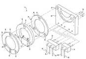
- FIG. 1is a top perspective of a current sensor in accordance with the present invention with parts shown in exploded relationship;
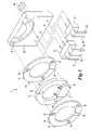
- FIG. 2is a corresponding top perspective with parts assembled.
- FIG. 3is a somewhat diagrammatic side elevation of the current sensor of FIG. 1 ;
- FIG. 4is a somewhat diagrammatic front elevation of the current sensor of FIG. 1 ;
- FIG. 5is a circuit diagram illustrating connection points of aspects of the circuit of the invention including a Hall effect generator and a temperature compensation circuit;
- FIG. 6is a graph illustrating performance of the current sensor in accordance with FIGS. 1-5 , but without the temperature compensation circuit;
- FIG. 7is another graph illustrating performance of the current sensor in accordance with FIGS. 1-5 , also without the temperature compensation circuit;
- FIG. 8is another graph illustrating performance of the current sensor of FIGS. 1-5 , including the temperature compensation circuit.
- FIG. 9is a circuit diagram of additional circuit components that may be used in the invention, including a temperature compensation circuit.
- the present inventionincludes a unique packaging of a Hall effect current sensor with increased sensitivity and linearity and reduced hysteresis and temperature variation.
- An embodiment of the current sensor system 10is shown diagrammatically in FIGS. 1 and 2 .
- a Hall effect generator chip 12is mounted between adjacent ends of an annular, horseshoe mounting member or spacer 14 of nonmagnetic material, such as a suitable plastic.
- the generatoris sensitive to the flux density (B field) tangential to its wide, flat top and bottom surfaces which can be coplanar with the flat surfaces of the spacer.
- the spacer and generatorare sandwiched between ferromagnetic rings 16 . Each ring has a large central opening and a small air gap 18 overlying/underlying the generator 12 .
- a circuit board 20has a semicircular mounting recess 22 that snugly receives approximately one-half of the circumference of the lower ferromagnetic ring 16 .
- Input/output blocks 24 , 26 with corresponding input and output leads 28are mounted on the board, as is a separate capacitor 30 .
- the conductor C for which current information is desiredpasses through the aligned central openings of the ferromagnetic rings 16 and spacer 14 .
- the current flowing in the conductorcreates a B field that will be contained in and concentrated by the ferromagnetic rings 16 .
- the ferromagnetic rings with the air gapsmagnify the field observed by the chip 12 , and at both sides of the chip.
- the double field magnificationcreates a greater sensitivity to the current in the conductor.
- the field that is tangential to the Hall effect generator 12will be detected and will be converted to a voltage that is proportional to the current in the conductor.
- a test coil TCcan be provided, so that a current can be applied to the test coil to test the magnetic circuit-current sensor operation.
- the voltage outputcan be measured and graphed as a function of the known current in the test coil.
- permalloy ferromagnetic ringsare used, such as Carpenter Steel HyMu80®, that are annealed for magnetic properties.
- This materialshould be annealed in a dry hydrogen or vacuum, oxygen-free atmosphere with a dew point below ⁇ 40° F. at 2050° F. to 2150° F. for 2 to 4 hours.
- the ringsare furnace cooled to 1100° F., and from 1100° F. to 700° F. at a rate between 350° F. to 600° F. per hour.
- an objectis to obtain very high permeability.
- the width of the air gap 18is determined experimentally for high sensitivity. In the described embodiment, an air gap of 40 mils has been found to be effective.
- the Hall effect generator 12can be a SENTRON 1SA-1V single-axis magnetic sensor in an SOIC-8 package.
- the spacer 14is made from 30% glass-filled polyetherimide (ULTEM2300).
- the ferromagnetic rings, spacer and Hall effect chipare aligned using the holes 32 and tabs 33 .
- the holescan be used with rivets to hold the rings and spacer together tightly against the Hall effect chip, and/or the parts can be secured with suitable adhesive.
- Metal etching primeris applied to metal surfaces where adhesives are used to bond the spacer, rings and Hall effect chip together.
- the Hall effect chip and the ferromagnetic assemblyare soldered onto the circuit board so that it does not contact the circuit board except at the Hall effect chip solder joints so that no thermal stresses can be applied to the ferromagnetic assembly.
- FIG. 5A circuit diagram is shown in FIG. 5 .
- the basic circuitis composed of the Hall effect generator 12 and a temperature compensating circuit 34 .
- the TC resistor for the ideal configurationwas 680 PPM per degrees C.
- FIG. 6displays voltage out versus current for the current sensor at 25° C. from ⁇ 6 to 6 amps DC. Voltage out was recorded while the current varied positive and negative multiple times to show any hysteresis effects. The hysteresis is very small. The sensitivity is 173 mv per amp and the linearity is very good with a perfect correlation coefficient of 1.
- FIG. 7shows the same graph for three temperatures ( ⁇ 55, 25 and 105° C.), still without a temperature compensation circuit. As temperature varies the linearity does not change appreciably, but the slope of the line or sensitivity does change slightly. The slope varies from about 165 to about 183 mv per amp in the tested temperature range, still very accurate at such small currents.
- FIG. 8shows the results when the temperature compensation circuit is incorporated to reduce the thermal dependence.
- the temperature compensated slopeonly varies from 173 to 174 mv per amp. Consequently, on the scale shown, the lines and test points overlie each other.
- the sensorprovides essentially identical outputs within the tested temperature range.
- the modified circuit shown in FIG. 9operates similarly to the circuit shown in FIG. 5 .
- the power input, ground, and capacitor (C) connections to the Hall effect generator 12are identical.
- the analog output (pin 7 , A_OUT) and the common output (pin 6 , CO_OUT)are both at a DC voltage level of 1 ⁇ 2 VDD with a 0 tangential B field. Using CO_OUT as a reference for the remainder of the signal conditioning circuit allows this circuit to operate from a single power supply.
- the DC voltage level from these two outputsvaries from device to device and also varies with temperature.
- the DC voltage temperature variation of the two outputstrack closely. This circuit topology allows errors in signal conditioning due to component parameter variation to be minimized.
- the sensor and signal conditioning circuitwork with both AC and DC currents.
- the amplifier and temperature compensation stage 34 following the sensor 12accomplishes two things.
- the firstis the bandwidth of the signal from the sensor is limited while balancing the impedances on the two inputs to the amplifier 35 . This is necessary if the sensor and circuit are to operate in harsh environments such as those found in the aerospace or automotive industries.
- the secondis the gain of this stage temperature compensates the slope variation in the sensor output due to temperature.
- the TC resistor for the ideal configurationwas 680 PPM per degrees C. The slope correction could be reversed if the TC resistor is placed in the feedback position instead of the input position.
- A_OUTresponds with an output positive relative to the CO_OUT reference and negative relative to the reference if the current is in the opposite direction.
- An absolute value and bandwidth limiting circuit 36converts the output from circuit 34 to a positive output relative to the CO_OUT reference regardless of the direction of the current in the wire looped through the sensor.
- Capacitor C 3can be chosen to be very large so that the output of the absolute value circuit is a DC value. This capacitor can also be chosen so that the absolute value output is a full wave rectified AC signal referenced to CO_OUT for applications requiring faster response.
- a reference-scaling amplifier 38derives the reference for a threshold detector 40 from the CO_OUT reference in the SENTRON device 12 . This also helps minimize errors due to component parameter variations since the detector reference varies with the absolute value circuit reference. Experimental results indicate that bandwidth limiting is also required here since noise from the input signal will also couple to the CO_OUT reference output. The bandwidth of the reference-scaling amplifier should be set to a value similar to that for the signal amplifier connected to the A_OUT sensor output.
- the threshold detector 40is a simple single-ended comparator since the absolute value circuit creates a positive output regardless of the direction of the current in the sensor.
- the threshold detectorcompares the absolute value output with the scaled reference and triggers follow on circuitry as the output of the comparator changes state.
- ferromagnetic ringsof a material with high permeability, preferably greater than 30,000.
- Hthe H field
- Idistance (airgap width and mean ferromagnetic diameter)
- Nnumber of “turns” (number of times the conductor passes through the sensor)
- Iconductor current
- ⁇permeability
- H airgap ⁇ l airgap + H core ⁇ l coreN turns ⁇ I wire EQ ⁇ ⁇ 1
- B airgap ⁇ l airgap ⁇ o + B core ⁇ l core ⁇ o ⁇ ⁇ coreN turns ⁇ I wire EQ ⁇ ⁇ 2
- EQ 3shows the sensitivity of the B ( ⁇ B) field in the air gap to the temperature change ( ⁇ T).
- Equation 2Equation 2
- B airgap ⁇ l airgap ⁇ oN turns ⁇ I wire EQ ⁇ ⁇ 4 and Equation 3 would reduce dramatically if not disappear, that is, temperature sensitivity is essentially eliminated.
- the designbecomes linear and reduces the variation over temperature.
- Permalloyif annealed correctly, can have a permeability of 30,000 to 100,000 and the magnetic hysteresis is almost nonexistent.
- a Hall devicethat is sensitive to fields that are tangential to the chip and two permalloy rings (field concentrators) preferably are used. In this case, the design will get two times the field change for a change in current.
- For the new designthere is improved linearity, low magnetic hysteresis, decreased sensitivity to temperature variation and twice the sensitivity. If an amplifier with a TC resistor is added to the output of the Hall device the temperature variation can be removed even more.
Landscapes
- Physics & Mathematics (AREA)
- General Physics & Mathematics (AREA)
- Measuring Instrument Details And Bridges, And Automatic Balancing Devices (AREA)
- Hall/Mr Elements (AREA)
- Measuring Magnetic Variables (AREA)
Abstract
Description
This application claims the benefit of application Ser. No. 60/671,237, filed Apr. 13, 2005.
Known current sensors have a magnetic circuit, typically a C-shaped core of magnetic material having adjacent ends separated by an air gap. The core is meant to concentrate the magnetic field emitted from a current-carrying conductor that may pass through the core one or more times, such as by being looped around a leg of the C. The core can be an open square, generally rectangular, or approximately circular, for example, and a Hall effect device is typically placed in the air gap between the opposing ends. The object is to detect the strength of the magnetic field in the air gap and supply a corresponding varying voltage signal. The following patents and patent publications show current sensors of the general type with which the present invention is concerned, such patents being expressly incorporated by reference herein:
| U.S. Pat./Publication No. | Issue Date | Inventor(s) | ||
| 5,923,162 | Jul. 13, 1999 | Drafts et al. | ||
| 6,005,383 | Dec. 21, 1999 | Savary et al. | ||
| 6,426,617 B1 | Jul. 30, 2002 | Haensgen et al. | ||
| 6,429,639 B1 | Aug. 6, 2002 | Pelly | ||
| 6,545,456 B1 | Apr. 8, 2003 | Radosevich et al. | ||
| 2004/0056647 A1 | Mar. 25, 2004 | Stauth et al. | ||
Accuracy of the known devices may depend on the working environment, and the devices may be subject to magnetic hysteresis, both of which may affect reliability, particularly when sensing smaller currents.
This summary is provided to introduce a selection of concepts in a simplified form that are further described below in the Detailed Description. This summary is not intended to identify key features of the claimed subject matter, nor is it intended to be used as an aid in determining the scope of the claimed subject matter.
The present invention provides a Hall effect current sensor with high sensitivity and linearity, and reduced hysteresis and temperature variation. In one aspect of the invention, a Hall effect generator chip is mounted between the ends of an annular, horseshoe or “C” spacer of nonmagnetic material. The spacer and generator are sandwiched between ferromagnetic rings. Each ring has a small air gap overlying or underlying the generator. The generator is sensitive to the flux density (B field) tangential to its flat top and bottom surfaces adjacent to the air gaps. The ferromagnetic rings act as the magnetic circuit, also known as the magnetic concentrator or core. The core-spacer-generator assembly can be compactly mounted on a circuit board with various leads (power, ground, output, test leads, etc.), and other circuits can be included to improve performance even further if desired.
The foregoing aspects and many of the attendant advantages of this invention will become more readily appreciated as the same become better understood by reference to the following detailed description, when taken in conjunction with the accompanying drawings, wherein:
The present invention includes a unique packaging of a Hall effect current sensor with increased sensitivity and linearity and reduced hysteresis and temperature variation. An embodiment of thecurrent sensor system 10 is shown diagrammatically inFIGS. 1 and 2 . A Halleffect generator chip 12 is mounted between adjacent ends of an annular, horseshoe mounting member orspacer 14 of nonmagnetic material, such as a suitable plastic. The generator is sensitive to the flux density (B field) tangential to its wide, flat top and bottom surfaces which can be coplanar with the flat surfaces of the spacer. The spacer and generator are sandwiched betweenferromagnetic rings 16. Each ring has a large central opening and asmall air gap 18 overlying/underlying thegenerator 12. Acircuit board 20 has a semicircular mounting recess22 that snugly receives approximately one-half of the circumference of the lowerferromagnetic ring 16. Input/output blocks output leads 28 are mounted on the board, as is aseparate capacitor 30.
With reference toFIG. 3 andFIG. 4 , the conductor C for which current information is desired passes through the aligned central openings of theferromagnetic rings 16 andspacer 14. The current flowing in the conductor creates a B field that will be contained in and concentrated by theferromagnetic rings 16. The ferromagnetic rings with the air gaps magnify the field observed by thechip 12, and at both sides of the chip. The double field magnification creates a greater sensitivity to the current in the conductor. The field that is tangential to theHall effect generator 12 will be detected and will be converted to a voltage that is proportional to the current in the conductor. As illustrated inFIG. 4 , a test coil TC can be provided, so that a current can be applied to the test coil to test the magnetic circuit-current sensor operation. The voltage output can be measured and graphed as a function of the known current in the test coil.
In a preferred embodiment, permalloy ferromagnetic rings are used, such as Carpenter Steel HyMu80®, that are annealed for magnetic properties. This material should be annealed in a dry hydrogen or vacuum, oxygen-free atmosphere with a dew point below −40° F. at 2050° F. to 2150° F. for 2 to 4 hours. The rings are furnace cooled to 1100° F., and from 1100° F. to 700° F. at a rate between 350° F. to 600° F. per hour. As shown below, an object is to obtain very high permeability. The width of theair gap 18 is determined experimentally for high sensitivity. In the described embodiment, an air gap of 40 mils has been found to be effective.
TheHall effect generator 12 can be a SENTRON 1SA-1V single-axis magnetic sensor in an SOIC-8 package. Thespacer 14 is made from 30% glass-filled polyetherimide (ULTEM2300). The ferromagnetic rings, spacer and Hall effect chip are aligned using theholes 32 andtabs 33. The holes can be used with rivets to hold the rings and spacer together tightly against the Hall effect chip, and/or the parts can be secured with suitable adhesive. Metal etching primer is applied to metal surfaces where adhesives are used to bond the spacer, rings and Hall effect chip together. The Hall effect chip and the ferromagnetic assembly are soldered onto the circuit board so that it does not contact the circuit board except at the Hall effect chip solder joints so that no thermal stresses can be applied to the ferromagnetic assembly.
A circuit diagram is shown inFIG. 5 . The basic circuit is composed of theHall effect generator 12 and atemperature compensating circuit 34. The TC resistor for the ideal configuration was 680 PPM per degrees C.
A current sensor in accordance with the above description was built and evaluated, but without thetemperature compensation circuit 34.FIG. 6 displays voltage out versus current for the current sensor at 25° C. from −6 to 6 amps DC. Voltage out was recorded while the current varied positive and negative multiple times to show any hysteresis effects. The hysteresis is very small. The sensitivity is 173 mv per amp and the linearity is very good with a perfect correlation coefficient of 1.
The modified circuit shown inFIG. 9 operates similarly to the circuit shown inFIG. 5 . The power input, ground, and capacitor (C) connections to theHall effect generator 12 are identical. The analog output (pin 7, A_OUT) and the common output (pin 6, CO_OUT) are both at a DC voltage level of ½ VDD with a 0 tangential B field. Using CO_OUT as a reference for the remainder of the signal conditioning circuit allows this circuit to operate from a single power supply.
The DC voltage level from these two outputs varies from device to device and also varies with temperature. The DC voltage temperature variation of the two outputs track closely. This circuit topology allows errors in signal conditioning due to component parameter variation to be minimized. The sensor and signal conditioning circuit work with both AC and DC currents.
The amplifier andtemperature compensation stage 34 following thesensor 12 accomplishes two things. The first is the bandwidth of the signal from the sensor is limited while balancing the impedances on the two inputs to the amplifier35. This is necessary if the sensor and circuit are to operate in harsh environments such as those found in the aerospace or automotive industries. The second is the gain of this stage temperature compensates the slope variation in the sensor output due to temperature. As noted above, the TC resistor for the ideal configuration was 680 PPM per degrees C. The slope correction could be reversed if the TC resistor is placed in the feedback position instead of the input position. As the current increases in the conductor looped through the sensor, A_OUT responds with an output positive relative to the CO_OUT reference and negative relative to the reference if the current is in the opposite direction. An absolute value and bandwidth limiting circuit36 converts the output fromcircuit 34 to a positive output relative to the CO_OUT reference regardless of the direction of the current in the wire looped through the sensor. Capacitor C3 can be chosen to be very large so that the output of the absolute value circuit is a DC value. This capacitor can also be chosen so that the absolute value output is a full wave rectified AC signal referenced to CO_OUT for applications requiring faster response.
A reference-scaling amplifier38 derives the reference for athreshold detector 40 from the CO_OUT reference in theSENTRON device 12. This also helps minimize errors due to component parameter variations since the detector reference varies with the absolute value circuit reference. Experimental results indicate that bandwidth limiting is also required here since noise from the input signal will also couple to the CO_OUT reference output. The bandwidth of the reference-scaling amplifier should be set to a value similar to that for the signal amplifier connected to the A_OUT sensor output.
Thethreshold detector 40 is a simple single-ended comparator since the absolute value circuit creates a positive output regardless of the direction of the current in the sensor. The threshold detector compares the absolute value output with the scaled reference and triggers follow on circuitry as the output of the comparator changes state.
Advantages are obtained by forming the ferromagnetic rings of a material with high permeability, preferably greater than 30,000. Using Ampere's law, the equation can be written for the flux concentrator (core) and the air gap as follows, where H represents the H field, I represents distance (airgap width and mean ferromagnetic diameter), N represents number of “turns” (number of times the conductor passes through the sensor), I represents conductor current, and μ represents permeability:
The objective is to increase the sensitivity to the current in the wire, reduce the magnetic hysteresis, reduce the variation over temperature and improve linearity. From
and
While illustrative embodiments have been illustrated and described, it will be appreciated that various changes can be made therein without departing from the spirit and scope of the invention.
Claims (11)
1. A sensor for sensing current flowing through a conductor comprising:
a nonmagnetic mounting member;
a Hall effect generator mounted on the member;
a first ferromagnetic ring of generally C shape having opposing ends separated by an air gap, the ferromagnetic ring being mounted with the air gap overlying the generator but without the generator protruding into the air gap, and at least one loop of the conductor passing through the ferromagnetic ring; and
a circuit including the generator for supplying an output as a function of the strength of a magnetic field having a direction tangential to the generator, which magnetic field is caused by current flowing through the conductor.
2. The sensor described inclaim 1 , including a second ferromagnetic ring having opposing ends separated by an air gap, the mounting member and generator being secured between the first and second ferromagnetic rings with the air gaps adjacent to the generator.
3. The sensor described inclaim 2 , in which each of the first and second ferromagnetic rings has a permeability of at least 30,000.
4. The sensor described inclaim 1 , including a circuit board having a semicircular mounting recess snugly receiving approximately one half of the circumference of the first ferromagnetic ring.
5. The sensor described inclaim 2 , including a circuit board having a semicircular mounting recess snugly receiving approximately one half of the circumference of the first ferromagnetic ring.
6. A sensor for sensing current flowing through a conductor comprising:
a nonmagnetic mounting member;
a Hall effect generator mounted on the member;
a first ferromagnetic ring of generally C shape having a central opening therethrough and opposing ends separated by a first narrow air gap, the first ferromagnetic ring being mounted with the first air gap overlying the generator but without the generator protruding into the first air gap, and with the conductor passing through the central opening of the first ferromagnetic ring; and
a circuit including the generator for supplying an output as a function of the strength of a magnetic field having a direction tangential to the generator, which magnetic field is caused by current flowing through the conductor.
7. The sensor described inclaim 6 , including a second ferromagnetic ring having a central opening therethrough and opposing ends separated by a second narrow air gap, the mounting member and generator being secured inbetween the first and second ferromagnetic rings with the central openings aligned axially and the air gaps adjacent to but on opposite sides of the generator.
8. The sensor described inclaim 7 , in which each of the first and second ferromagnetic rings has a permeability of at least 30,000.
9. The sensor described inclaim 6 , including a circuit board having a semicircular mounting recess snugly receiving approximately one half of the circumference of first ferromagnetic ring.
10. The sensor described inclaim 7 , including a circuit board having a semicircular mounting recess snugly receiving approximately one half of the circumference of the first ferromagnetic ring.
11. A sensor for sensing current flowing through a conductor comprising:
a horseshoe spacer ring of nonmagnetic material having opposite ends facing each other and separated by a gap;
a Hall effect generator mounted between the ends of the spacer;
a first ferromagnetic ring of generally C shape having a central opening and opposite ends facing each other and separated from each other by one and only one first narrow air gap, the first ferromagnetic ring being mounted with the air gap overlying the generator but without the generator protruding into the air gap;
a second ferromagnetic ring of generally C shape having a central opening and opposing ends facing each other and separated by one and only one second narrow air gap, the second ferromagnetic ring being mounted with the second air gap underlying the generator but without the generator protruding into the second air gap, at least one section of the conductor passing through the ferromagnetic rings; and
a circuit including the generator for supplying an output as the function of the strength of a magnetic field having a direction tangential to the generator, which magnetic field is caused by current flowing through the conductor, the horseshoe spacer being sandwiched between the first and second ferromagnetic rings with the respective air gaps at opposite sides of the Hall effective generator.
Priority Applications (1)
| Application Number | Priority Date | Filing Date | Title |
|---|---|---|---|
| US11/403,544US7298132B2 (en) | 2005-04-13 | 2006-04-13 | Current sensor |
Applications Claiming Priority (2)
| Application Number | Priority Date | Filing Date | Title |
|---|---|---|---|
| US67123705P | 2005-04-13 | 2005-04-13 | |
| US11/403,544US7298132B2 (en) | 2005-04-13 | 2006-04-13 | Current sensor |
Publications (2)
| Publication Number | Publication Date |
|---|---|
| US20060232902A1 US20060232902A1 (en) | 2006-10-19 |
| US7298132B2true US7298132B2 (en) | 2007-11-20 |
Family
ID=37115741
Family Applications (1)
| Application Number | Title | Priority Date | Filing Date |
|---|---|---|---|
| US11/403,544ActiveUS7298132B2 (en) | 2005-04-13 | 2006-04-13 | Current sensor |
Country Status (2)
| Country | Link |
|---|---|
| US (1) | US7298132B2 (en) |
| WO (1) | WO2006113459A2 (en) |
Cited By (13)
| Publication number | Priority date | Publication date | Assignee | Title |
|---|---|---|---|---|
| US20090027047A1 (en)* | 2007-07-26 | 2009-01-29 | Honeywell International Inc. | Current sensor having sandwiched magnetic permeability layer |
| US20100320956A1 (en)* | 2007-09-14 | 2010-12-23 | The Powerwise Group, Inc. | Energy Saving System and Method for Devices with Rotating or Reciprocating Masses |
| US20110115466A1 (en)* | 2006-03-31 | 2011-05-19 | Daihen Corporation | Current detection printed board, voltage detection printed board, current/voltage detection printed board, current/voltage detector, current detector and voltage detector |
| US8004255B2 (en) | 2008-08-07 | 2011-08-23 | The Powerwise Group, Inc. | Power supply for IGBT/FET drivers |
| US8085010B2 (en) | 2007-08-24 | 2011-12-27 | The Powerwise Group, Inc. | TRIAC/SCR-based energy savings device for reducing a predetermined amount of voltage using pulse width modulation |
| US8085009B2 (en) | 2007-08-13 | 2011-12-27 | The Powerwise Group, Inc. | IGBT/FET-based energy savings device for reducing a predetermined amount of voltage using pulse width modulation |
| US8120307B2 (en) | 2007-08-24 | 2012-02-21 | The Powerwise Group, Inc. | System and method for providing constant loading in AC power applications |
| US8619443B2 (en) | 2010-09-29 | 2013-12-31 | The Powerwise Group, Inc. | System and method to boost voltage |
| US8698446B2 (en) | 2009-09-08 | 2014-04-15 | The Powerwise Group, Inc. | Method to save energy for devices with rotating or reciprocating masses |
| US8698447B2 (en) | 2007-09-14 | 2014-04-15 | The Powerwise Group, Inc. | Energy saving system and method for devices with rotating or reciprocating masses |
| US8810190B2 (en) | 2007-09-14 | 2014-08-19 | The Powerwise Group, Inc. | Motor controller system and method for maximizing energy savings |
| US20140254630A1 (en)* | 2013-03-06 | 2014-09-11 | Microchip Technology Incorporated | Single Wire Analog Output Sensor Architecture |
| US9297864B2 (en) | 2010-05-19 | 2016-03-29 | Power Distribution, Inc. | Current metering and abnormal event monitoring system |
Families Citing this family (18)
| Publication number | Priority date | Publication date | Assignee | Title |
|---|---|---|---|---|
| JP2010019586A (en)* | 2008-07-08 | 2010-01-28 | Panasonic Corp | Current sensor |
| US7642768B1 (en)* | 2008-10-21 | 2010-01-05 | Honeywell International Inc. | Current sensor having field screening arrangement including electrical conductors sandwiching magnetic permeability layer |
| DE102009054943A1 (en)* | 2009-12-18 | 2011-06-22 | SB LiMotive Company Ltd., Kyonggi | Current sensor with self-test function |
| JP5660911B2 (en)* | 2011-01-28 | 2015-01-28 | 三菱航空機株式会社 | Lightning current detection sensor |
| CN202661525U (en)* | 2012-01-19 | 2013-01-09 | 邹高芝 | Coaxial double-loop magnetic core structure assembly for core-through type high precision opened-loop type Hall current sensor |
| CN202661526U (en)* | 2012-01-19 | 2013-01-09 | 邹高芝 | Coaxial double-loop magnetic core coil assembly for core-through type high precision closed-loop type Hall current sensor |
| RU2531040C1 (en)* | 2013-05-31 | 2014-10-20 | Федеральное государственное бюджетное образовательное учреждение высшего профессионального образования "Кузбасский государственный технический университет имени Т.Ф. Горбачева" (КузГТУ) | Insulated current sensor |
| US9535098B2 (en)* | 2013-09-02 | 2017-01-03 | Senis Ag | Current transducer for measuring an electrical current |
| JP6223856B2 (en)* | 2014-02-21 | 2017-11-01 | 大崎電気工業株式会社 | Current detection structure |
| EP3125841B1 (en)* | 2014-04-04 | 2020-05-13 | Trafimet Group S.p.A. | Welding and/or cutting unit with sensor for detecting/measuring the welding and/or cutting current |
| WO2016125367A1 (en)* | 2015-02-02 | 2016-08-11 | 株式会社村田製作所 | Current sensor |
| US10878997B2 (en) | 2015-03-13 | 2020-12-29 | Taiwan Semiconductor Manufacturing Company, Ltd. | Integrated circuit having current-sensing coil |
| KR102141598B1 (en)* | 2018-11-22 | 2020-08-05 | 주식회사 아이티엑스엠투엠 | An apparatus and a method of current measurement with compensation capability based on system information |
| WO2020107426A1 (en)* | 2018-11-30 | 2020-06-04 | Siemens Ltd., China | Current measurement apparatus |
| US20220155352A1 (en)* | 2019-03-18 | 2022-05-19 | Dima Cheskis | Low current hall effect sensor |
| DE102020211526A1 (en)* | 2019-09-20 | 2021-03-25 | Robert Bosch Gesellschaft mit beschränkter Haftung | Sensor device with sensor and converter |
| EP3958003A1 (en)* | 2020-08-18 | 2022-02-23 | Siemens Aktiengesellschaft | Current measuring device with hall sensors |
| CA3151025A1 (en)* | 2021-03-05 | 2022-09-05 | Eaton Intelligent Power Limited | Leakage current detection in cable tray |
Citations (11)
| Publication number | Priority date | Publication date | Assignee | Title |
|---|---|---|---|---|
| US4002967A (en)* | 1975-08-01 | 1977-01-11 | Aluminum Company Of America | Annular eddy current test coil with magnetic laminations adjacent a limited circumferential extent |
| US5416407A (en)* | 1993-06-11 | 1995-05-16 | F. W. Bell, Inc. | Electric current sensor employing hall effect generator |
| US5734535A (en)* | 1995-06-19 | 1998-03-31 | Sankyo Seiki Mfg. Co., Ltd. | Magnetic head with a useable lifetime detection mechanism |
| US5874848A (en)* | 1997-07-09 | 1999-02-23 | Bell Technologies, Inc. | Electric current sensor utilizing a compensating trace configuration |
| US5923162A (en) | 1997-04-18 | 1999-07-13 | Bell Technologies Inc. | Non-inductive lead path hall effect electrical current sensor |
| US6005383A (en) | 1995-03-24 | 1999-12-21 | Liasons Electroniques-Mecaniques Lem S.A. | Electrical current sensor with magnetic field detector |
| US6426617B1 (en) | 1999-09-28 | 2002-07-30 | Rockwell Automation Technologies, Inc. | Hall effect current sensor system packaging |
| US6429639B1 (en) | 1997-01-21 | 2002-08-06 | International Rectifier Corporation | Combined filter inductor and hall current sensor |
| US6545456B1 (en) | 1998-08-12 | 2003-04-08 | Rockwell Automation Technologies, Inc. | Hall effect current sensor package for sensing electrical current in an electrical conductor |
| US20040056647A1 (en) | 2002-09-20 | 2004-03-25 | Jason Stauth | Integrated current sensor |
| US20060255793A1 (en)* | 2005-05-12 | 2006-11-16 | Michel Montreuil | Current sensor |
- 2006
- 2006-04-13USUS11/403,544patent/US7298132B2/enactiveActive
- 2006-04-13WOPCT/US2006/014115patent/WO2006113459A2/enactiveApplication Filing
Patent Citations (11)
| Publication number | Priority date | Publication date | Assignee | Title |
|---|---|---|---|---|
| US4002967A (en)* | 1975-08-01 | 1977-01-11 | Aluminum Company Of America | Annular eddy current test coil with magnetic laminations adjacent a limited circumferential extent |
| US5416407A (en)* | 1993-06-11 | 1995-05-16 | F. W. Bell, Inc. | Electric current sensor employing hall effect generator |
| US6005383A (en) | 1995-03-24 | 1999-12-21 | Liasons Electroniques-Mecaniques Lem S.A. | Electrical current sensor with magnetic field detector |
| US5734535A (en)* | 1995-06-19 | 1998-03-31 | Sankyo Seiki Mfg. Co., Ltd. | Magnetic head with a useable lifetime detection mechanism |
| US6429639B1 (en) | 1997-01-21 | 2002-08-06 | International Rectifier Corporation | Combined filter inductor and hall current sensor |
| US5923162A (en) | 1997-04-18 | 1999-07-13 | Bell Technologies Inc. | Non-inductive lead path hall effect electrical current sensor |
| US5874848A (en)* | 1997-07-09 | 1999-02-23 | Bell Technologies, Inc. | Electric current sensor utilizing a compensating trace configuration |
| US6545456B1 (en) | 1998-08-12 | 2003-04-08 | Rockwell Automation Technologies, Inc. | Hall effect current sensor package for sensing electrical current in an electrical conductor |
| US6426617B1 (en) | 1999-09-28 | 2002-07-30 | Rockwell Automation Technologies, Inc. | Hall effect current sensor system packaging |
| US20040056647A1 (en) | 2002-09-20 | 2004-03-25 | Jason Stauth | Integrated current sensor |
| US20060255793A1 (en)* | 2005-05-12 | 2006-11-16 | Michel Montreuil | Current sensor |
Cited By (24)
| Publication number | Priority date | Publication date | Assignee | Title |
|---|---|---|---|---|
| US8629674B2 (en) | 2006-03-31 | 2014-01-14 | Daihen Corporation | Current detection printed board, voltage detection printed board, current/voltage detection printed board, current/voltage detector, current detector and voltage detector |
| US20110115466A1 (en)* | 2006-03-31 | 2011-05-19 | Daihen Corporation | Current detection printed board, voltage detection printed board, current/voltage detection printed board, current/voltage detector, current detector and voltage detector |
| US8427134B2 (en)* | 2006-03-31 | 2013-04-23 | Daihen Corporation | Current detection printed board, voltage detection printed board, current/voltage detection printed board, current/voltage detector, current detector and voltage detector |
| US7612553B2 (en)* | 2007-07-26 | 2009-11-03 | Honeywell International Inc. | Current sensor having sandwiched magnetic permeability layer |
| US20090027047A1 (en)* | 2007-07-26 | 2009-01-29 | Honeywell International Inc. | Current sensor having sandwiched magnetic permeability layer |
| US9716431B2 (en) | 2007-08-13 | 2017-07-25 | The Powerwise Group, Inc. | IGBT/FET-based energy savings device for reducing a predetermined amount of voltage using pulse width modulation |
| US8723488B2 (en) | 2007-08-13 | 2014-05-13 | The Powerwise Group, Inc. | IGBT/FET-based energy savings device for reducing a predetermined amount of voltage using pulse width modulation |
| US8085009B2 (en) | 2007-08-13 | 2011-12-27 | The Powerwise Group, Inc. | IGBT/FET-based energy savings device for reducing a predetermined amount of voltage using pulse width modulation |
| US8085010B2 (en) | 2007-08-24 | 2011-12-27 | The Powerwise Group, Inc. | TRIAC/SCR-based energy savings device for reducing a predetermined amount of voltage using pulse width modulation |
| US8120307B2 (en) | 2007-08-24 | 2012-02-21 | The Powerwise Group, Inc. | System and method for providing constant loading in AC power applications |
| US8698447B2 (en) | 2007-09-14 | 2014-04-15 | The Powerwise Group, Inc. | Energy saving system and method for devices with rotating or reciprocating masses |
| US9628015B2 (en) | 2007-09-14 | 2017-04-18 | The Powerwise Group, Inc. | Energy saving system and method for devices with rotating or reciprocating masses |
| US20100320956A1 (en)* | 2007-09-14 | 2010-12-23 | The Powerwise Group, Inc. | Energy Saving System and Method for Devices with Rotating or Reciprocating Masses |
| US9716449B2 (en) | 2007-09-14 | 2017-07-25 | The Powerwise Group, Inc. | Energy saving system and method for devices with rotating or reciprocating masses |
| US8810190B2 (en) | 2007-09-14 | 2014-08-19 | The Powerwise Group, Inc. | Motor controller system and method for maximizing energy savings |
| US8823314B2 (en) | 2007-09-14 | 2014-09-02 | The Powerwise Group, Inc. | Energy saving system and method for devices with rotating or reciprocating masses |
| US8004255B2 (en) | 2008-08-07 | 2011-08-23 | The Powerwise Group, Inc. | Power supply for IGBT/FET drivers |
| US9240745B2 (en) | 2009-09-08 | 2016-01-19 | The Powerwise Group, Inc. | System and method for saving energy when driving masses having periodic load variations |
| US8698446B2 (en) | 2009-09-08 | 2014-04-15 | The Powerwise Group, Inc. | Method to save energy for devices with rotating or reciprocating masses |
| US9297864B2 (en) | 2010-05-19 | 2016-03-29 | Power Distribution, Inc. | Current metering and abnormal event monitoring system |
| US8619443B2 (en) | 2010-09-29 | 2013-12-31 | The Powerwise Group, Inc. | System and method to boost voltage |
| US20140254630A1 (en)* | 2013-03-06 | 2014-09-11 | Microchip Technology Incorporated | Single Wire Analog Output Sensor Architecture |
| US9176011B2 (en)* | 2013-03-06 | 2015-11-03 | Microchip Technology Incorporated | Single wire analog output sensor architecture |
| TWI631322B (en)* | 2013-03-06 | 2018-08-01 | 美商微晶片科技公司 | Single wire analog output sensor architecture |
Also Published As
| Publication number | Publication date |
|---|---|
| WO2006113459A2 (en) | 2006-10-26 |
| US20060232902A1 (en) | 2006-10-19 |
| WO2006113459A3 (en) | 2007-04-12 |
Similar Documents
| Publication | Publication Date | Title |
|---|---|---|
| US7298132B2 (en) | Current sensor | |
| US7053600B2 (en) | Current sensor | |
| US8063634B2 (en) | Electronic circuit and method for resetting a magnetoresistance element | |
| US7746056B2 (en) | Integrated sensor | |
| US20050073292A1 (en) | System and method for current sensing using anti-differential, error correcting current sensing | |
| US7279885B2 (en) | Temperature compensated current sensor using reference magnetic field | |
| US7365535B2 (en) | Closed-loop magnetic sensor system | |
| EP1367401A4 (en) | CURRENT SENSOR AND OVERLOAD CURRENT PROTECTION DEVICE COMPRISING THE SAME | |
| US20010040241A1 (en) | Semiconductor device | |
| JP2002243766A (en) | Current sensor | |
| WO2002101396A1 (en) | Magnetic sensor | |
| Borole et al. | Design, development, and performance evaluation of GMR-based current sensor for industrial and aerospace applications | |
| JPH02170061A (en) | power detection device | |
| JP4253084B2 (en) | Load measuring device | |
| JP7119695B2 (en) | magnetic sensor | |
| JP7286932B2 (en) | magnetic sensor | |
| JP2007033222A (en) | Current sensor | |
| JPH08233867A (en) | Bridge detection circuit | |
| JP2006003209A (en) | Current detector | |
| TWI888803B (en) | Current measuring device | |
| JP6644343B1 (en) | Zero flux type magnetic sensor | |
| JP2001141756A (en) | Current sensor | |
| WO2001033242A1 (en) | A thin magnetoresistive current sensor system | |
| JPH0211023B2 (en) | ||
| JP2019174436A (en) | Magnetic sensor |
Legal Events
| Date | Code | Title | Description |
|---|---|---|---|
| AS | Assignment | Owner name:CRANE CO., WASHINGTON Free format text:ASSIGNMENT OF ASSIGNORS INTEREST;ASSIGNORS:WOOLSEY, KEVIN;MARION, L. MARK;KNUDSON, STEVEN;REEL/FRAME:017784/0378 Effective date:20060605 | |
| STCF | Information on status: patent grant | Free format text:PATENTED CASE | |
| CC | Certificate of correction | ||
| FPAY | Fee payment | Year of fee payment:4 | |
| FPAY | Fee payment | Year of fee payment:8 | |
| MAFP | Maintenance fee payment | Free format text:PAYMENT OF MAINTENANCE FEE, 12TH YEAR, LARGE ENTITY (ORIGINAL EVENT CODE: M1553); ENTITY STATUS OF PATENT OWNER: LARGE ENTITY Year of fee payment:12 | |
| AS | Assignment | Owner name:CRANE HOLDINGS, CO., CONNECTICUT Free format text:ASSIGNMENT OF ASSIGNORS INTEREST;ASSIGNOR:CRANE CO.;REEL/FRAME:059963/0621 Effective date:20220518 | |
| AS | Assignment | Owner name:ELDEC AEROSPACE CORP., WASHINGTON Free format text:ASSIGNMENT OF ASSIGNORS INTEREST;ASSIGNOR:CRANE HOLDINGS, CO.;REEL/FRAME:060822/0394 Effective date:20220811 |