US7297912B1 - Circuit and method for reducing power consumption in an optical navigation system having redundant arrays - Google Patents
Circuit and method for reducing power consumption in an optical navigation system having redundant arraysDownload PDFInfo
- Publication number
- US7297912B1 US7297912B1US11/389,903US38990306AUS7297912B1US 7297912 B1US7297912 B1US 7297912B1US 38990306 AUS38990306 AUS 38990306AUS 7297912 B1US7297912 B1US 7297912B1
- Authority
- US
- United States
- Prior art keywords
- navigation system
- sensor
- array
- optical navigation
- optical
- Prior art date
- Legal status (The legal status is an assumption and is not a legal conclusion. Google has not performed a legal analysis and makes no representation as to the accuracy of the status listed.)
- Active, expires
Links
- 230000003287optical effectEffects0.000titleclaimsabstractdescription98
- 238000003491arrayMethods0.000titleclaimsabstractdescription46
- 238000000034methodMethods0.000titleclaimsabstractdescription33
- 238000006073displacement reactionMethods0.000claimsabstractdescription13
- 230000004044responseEffects0.000claimsabstractdescription9
- 238000003384imaging methodMethods0.000claimsabstractdescription4
- 238000005286illuminationMethods0.000claimsdescription8
- 238000013507mappingMethods0.000claims1
- 241000699666Mus <mouse, genus>Species0.000description12
- 238000005562fadingMethods0.000description12
- 238000010586diagramMethods0.000description8
- 238000012545processingMethods0.000description5
- 230000009467reductionEffects0.000description5
- 230000008901benefitEffects0.000description4
- 238000013461designMethods0.000description3
- 238000001514detection methodMethods0.000description3
- 230000006872improvementEffects0.000description3
- 238000005259measurementMethods0.000description3
- 238000012935AveragingMethods0.000description2
- 241000699670Mus sp.Species0.000description2
- 238000004364calculation methodMethods0.000description2
- 230000008859changeEffects0.000description2
- 238000011960computer-aided designMethods0.000description2
- 238000009826distributionMethods0.000description2
- 230000009977dual effectEffects0.000description2
- 230000000737periodic effectEffects0.000description2
- 238000005070samplingMethods0.000description2
- 230000003321amplificationEffects0.000description1
- 238000013459approachMethods0.000description1
- 238000006243chemical reactionMethods0.000description1
- 230000001427coherent effectEffects0.000description1
- 238000012937correctionMethods0.000description1
- 238000005520cutting processMethods0.000description1
- 230000000694effectsEffects0.000description1
- 238000005516engineering processMethods0.000description1
- 230000005669field effectEffects0.000description1
- 238000004519manufacturing processMethods0.000description1
- 238000012986modificationMethods0.000description1
- 230000004048modificationEffects0.000description1
- 238000012544monitoring processMethods0.000description1
- 238000003199nucleic acid amplification methodMethods0.000description1
- 238000003672processing methodMethods0.000description1
- 238000012360testing methodMethods0.000description1
Images


Classifications
- G—PHYSICS
- G01—MEASURING; TESTING
- G01J—MEASUREMENT OF INTENSITY, VELOCITY, SPECTRAL CONTENT, POLARISATION, PHASE OR PULSE CHARACTERISTICS OF INFRARED, VISIBLE OR ULTRAVIOLET LIGHT; COLORIMETRY; RADIATION PYROMETRY
- G01J1/00—Photometry, e.g. photographic exposure meter
- G01J1/10—Photometry, e.g. photographic exposure meter by comparison with reference light or electric value provisionally void
- G01J1/20—Photometry, e.g. photographic exposure meter by comparison with reference light or electric value provisionally void intensity of the measured or reference value being varied to equalise their effects at the detectors, e.g. by varying incidence angle
- G01J1/28—Photometry, e.g. photographic exposure meter by comparison with reference light or electric value provisionally void intensity of the measured or reference value being varied to equalise their effects at the detectors, e.g. by varying incidence angle using variation of intensity or distance of source
- G01J1/30—Photometry, e.g. photographic exposure meter by comparison with reference light or electric value provisionally void intensity of the measured or reference value being varied to equalise their effects at the detectors, e.g. by varying incidence angle using variation of intensity or distance of source using electric radiation detectors
- G01J1/32—Photometry, e.g. photographic exposure meter by comparison with reference light or electric value provisionally void intensity of the measured or reference value being varied to equalise their effects at the detectors, e.g. by varying incidence angle using variation of intensity or distance of source using electric radiation detectors adapted for automatic variation of the measured or reference value
Definitions
- the present inventionrelates generally to optical navigation systems, and more particularly to a circuit and method for use with an optical navigation system having redundant array to reduce power consumption therein.
- Optical navigation systems used in devicesare well known for inputting data into and interfacing with personal computers and workstations.
- Such devicesallow rapid relocation of a cursor on a monitor, and are useful in many text, database and graphical programs.
- a usercontrols the cursor, for example, by moving the mouse over a surface to move the cursor in a direction and over distance proportional to the movement of the mouse.
- movement of the hand over a stationary devicemay be used for the same purpose.
- One technology used for optical mice todayrelies on a light source illuminating a surface, and a two-dimensional (2D) array of photosensitive elements or detectors, such as photodiodes, in which the output of the individual elements in the array are combined or wired together in a repeating pattern spanning two or more detectors to track motion along one axis or in one dimension.
- the detectorsare wired in groups to detect of motion through movement of a light-dark pattern known as speckle.
- Speckleis the complex interference pattern generated by scattering of coherent light off of an optically rough surface and detected by a photosensitive element, such as a photodiode, with a finite angular field-of-view or numerical aperture.
- the image mapped to or captured on the comb-arraymay be magnified or de-magnified to achieve matching and so that the distribution of spatial frequencies in the image is roughly centered around the spatial frequencies of the array.
- signal processingit is possible to track the movement of this image as it moves back and forth across the comb-array and from that tracking derive the motion of the surface relative to the array.
- the present inventionprovides a solution to this and other problems, and offers further advantages over conventional optical navigation systems.
- FIG. 1is a functional block diagram of a speckle-based optical navigation system for which a circuit and method according to the present invention is particularly useful;
- FIGS. 2A and 2Bare schematic block diagrams of two redundant 2D comb-arrays arranged in quadrants according to an embodiment of the present invention
- FIG. 3is a block diagram of a circuit according to an embodiment of the present invention for reducing power consumption in an optical navigation system having redundant arrays;
- FIG. 4is a flowchart of a method for reducing power consumption in an optical navigation system having redundant arrays according to an embodiment of the present invention.
- FIG. 5is a block diagram of an automatic gain control (AGC) circuit for controlling illumination levels in an optical navigation system according to an embodiment of the present invention.
- AGCautomatic gain control
- the present inventionis directed generally to optical navigation systems and more particularly to a control circuit and method for use with an optical navigation system having redundant arrays to reduce power consumption therein.
- Optical navigation systemscan include, for example, an optical computer mouse, trackballs and the like, and are well known for inputting data into and interfacing with personal computers and workstations.
- optical navigation systemscan include, for example, an optical computer mouse, trackballs and the like, and are well known for inputting data into and interfacing with personal computers and workstations.
- many of the details of optical navigation systems in general and optical sensors for optical navigation systems in particular that are widely known and are not relevant to the present inventionhave been omitted from the following description.
- Optical navigation systems and optical sensorsare described, for example, in co-pending, commonly assigned U.S. patent application Ser. No. 11/355,551, entitled, “Circuit and Method for Determining Motion with Redundant Comb-Array,” filed on Feb. 16, 2006 by Yansun Xu et al., and incorporated herein by reference in its entirety.
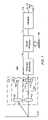
- FIG. 1is a functional block diagram of one embodiment of an optical navigation system for which the control circuit and method of the present invention is particularly useful.
- an optical navigation system 100generally includes an optical head 102 having an illuminator 104 with a light source 106 and illumination optics 108 to illuminate a portion of a surface 110 , imaging optics 112 to map or image a pattern of the by the surface, and an optical sensor 114 to sense or detect change in the pattern.
- the optical sensor 114includes one or more one-dimensional (1D) or two-dimensional (2D) arrays 116 each having a number of photosensitive elements, such as photodiodes 118 , on which light reflected from the surface 110 , is received.
- the array(s) 116may be configured to provide displacement measurements along any number of axes, for example along two orthogonal axes, x and y.
- the optical navigation system 100further includes front-end electrics 120 , signal processor 122 , and interface circuitry 124 .
- groups of photodiodes 118 in the array(s) 116may be combined using passive electronic components in the front-end electrics 120 to produce group signals.
- These group signalsmay be subsequently algebraically combined by the signal processor 122 using an algorithm 126 to produce to produce a signal providing information on the magnitude and direction of displacement of the sensor 114 in x and y directions.
- the signalmay be converted by the interface circuitry 124 to produce ⁇ x, ⁇ y data 128 which may be output by the system 100 .
- the circuit and method of the present inventionis applicable to both speckle and non-speckle based optical sensors having either multiple 1D arrays or 2D arrays.
- the 2D arraymay be either a periodic, 2D comb-array, which includes a number of regularly spaced photosensitive elements having 1D or 2D periodicity, a quasi-periodic 2D array (such as one having Penrose tiling), or a non-periodic 2D array, which has a regular pattern but does not include periodicities.
- the optical sensoris a speckle based optical sensor including redundant 2D comb-arrays of detectors or photosensitive elements arranged in two dimensions as shown in FIGS. 2A and 2B .
- the 2D comb-arrayoffers a simplicity of design and several further advantages over the conventional, non-speckle based or correlation sensors including: (i) faster signal processing; (ii) reduced power consumption; (iii) high angular accuracy; and (iv) performance that is independent of a direction of movement relative to an array orientation.
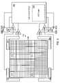
- FIGS. 2A and 2Bare schematic block diagrams of an optical sensor 202 having two redundant 2D comb-arrays or array-pairs arranged in quadrants 204 , 206 , 208 and 210 according to an embodiment of the present invention.
- Diagonally opposing quadrants 204 and 206are connected and form a first single array-pair or first 2D comb-array.
- Opposing quadrants 208 and 210are connected and form a second single array-pair or second 2D comb-array.
- each quadrant or sub-array 204 , 206 , 208 and 210has multiple photosensitive elements 211 arranged or grouped into cells 212 , each cell having photosensitive elements grouped in a 4 ⁇ 4 elements-per-cell (or 4 ⁇ 4 elements/period) configuration.
- Photosensitive elements 211 within a cell 212 with the same letter and same number, as shown in the detail of FIG. 2B , as well as corresponding elements of all cells in an array-pair ( 204 and 206 , or 208 and 210 ) with the same letter and number,are electrically connected or wired-sum to yield sixteen (16) wired-sum signals 214 .
- the 16 wired-sum signals 214are further combined with analog sensor circuits 216 and 218 in the signal processor 220 to produce eight (8) signals, CC 1 , CS 1 , SC 1 , SS 1 from the first 2D comb-array, and CC 2 , CS 2 , SC 2 , SS 2 from the second 2D comb-array.
- the strengths of the signals from either of the 2D comb-arrays or array-pairsmay decrease because the selected spatial frequency component is weak at some particular location on the surface, or because contributions from various parts of the array add coherently to zero.
- the square symmetry arrangement of the optical sensor 202enables simple and efficient illumination of all photosensitive elements 211 in the optical sensor.
- FIGS. 2A and 2Bare equal in size and square, it will be understood that this is a particular embodiment of a 2D comb-array which is not necessary to practice the invention.
- a signal processing method for combining the motion data derived from the redundant arrays or array-pairs to minimize the impact of signal fading on the overall performance of the systemwill now be described in detail with reference to FIGS. 2A and 2B .
- the image captured on the 2D comb-array of FIGS. 2A and 2Bis (de)-magnified such that the spatial frequency distribution of the image is roughly centered around the spatial frequency of the detector array.
- the four quasi-sinusoidal outputs (CC, CS, SC, and SS)representing separate in-phase and quadrature signals for motion along two orthogonal axes, it is possible to track the 2D movement of the image as it moves across the detector array and derive the motion of the surface relative to the detector array along the two orthogonal axes.
- the phase angle value in an x direction, ⁇ xcan be computed using equation 1.0 shown below.
- ⁇ xis the phase angle value in the x direction
- CC, CS, SC, and SSare the four quasi-sinusoidal output signals from the array shown in FIG. 2A and described above.
- phase angle value in a y direction⁇ y .
- ⁇ ytan - 1 ⁇ ( CS - SC CC + SS ) ( 2.0 )
- the velocity of the movement of the sensor relative to the surfacecan now be determined by tracking the phase angle changes over time, that is from frame to frame using the following equation:
- phase angle changes ⁇ x and ⁇ yrepresent the movement of an image across the detector in 2D.
- the phase angle changes ⁇ x and ⁇ y from the previous sample frameare proportional to the detected 2D displacements along the two orthogonal axes between the current and previous sample frames.
- ⁇ t or the sampling rateis constant velocity is proportional to ⁇ . Accordingly, the terms velocity and ⁇ are used interchangeably throughout the remainder of this description.
- R x and R yindicate the contrast of the detected quasi-sinusoidal signals, and can be used as weighting factors in average velocity calculations and/or as an indication of quality of the received signal.
- phase angle values ⁇ x and ⁇ y as well as radius values R x and R yare computed.
- R x and R yindicate the contrast of the detected quasi-sinusoidal signals.
- the phase angle changes ⁇ x and ⁇ yare proportional to the 2D displacements along the two orthogonal axes.
- ⁇ x and ⁇ yare computed from the phase angle values for two successive frames using the following equations:
- phase angle changes ⁇ x and ⁇ yneed to be unwrapped to account for any additional full 2 ⁇ rotations that may have occurred between the two sample frames.
- unwrappingis accomplished using a velocity predictor as described, for example, in co-pending, commonly assigned U.S. patent application Ser. No. 11/324,424, entitled, “Method For Determining Motion Using A Velocity Predictor,” filed on Jan. 3, 2006 by Yansun Xu et al., and incorporated herein by reference in its entirety.
- a method for detecting motion of an optical sensor relative to a surface using unwrapped phase angle changes ( ⁇ x1 , ⁇ x2 ) and radius-weighted-averagingwill now be described. Briefly, the method involves: (i) generating for each array a first set of quasi-sinusoidal signals (CC, CS, SC, and SS) at a first time and a second set of quasi-sinusoidal signals at a second time in response to motion of light in at least a first direction (x) received thereon (ii) computing from the first and second sets of quasi-sinusoidal signals from each of the arrays phase angle changes ( ⁇ x1 , ⁇ x2 ) for the first and second sets of quasi-sinusoidal signals received from each of the arrays; (iii) computing from the first and second sets of quasi-sinusoidal signals from each of the arrays radius values (R x1 , R x2 ) for the first and second sets of quasi-sinusoidal signals received from each
- the velocity predictorsare computed using average velocity values (unwrapped average phase angle changes) from K preceding successive frames by: (i) calculating the number of full 2 ⁇ rotations needed to unwrap the phase angle changes for each direction using the current velocity predictors; and (ii) computing the unwrapped or corrected phase angle changes.
- This correction or unwrappingis expressed mathematically in the following equations:
- ⁇ ⁇ ⁇ ⁇ x⁇ x - 2 ⁇ ⁇ ⁇ INTEGER ⁇ ( ⁇ x - ⁇ ⁇ x ⁇ + ⁇ 2 ⁇ ⁇ ) ( 8.0 )
- ⁇ y⁇ y - 2 ⁇ ⁇ ⁇ INTEGER ⁇ ( ⁇ y - ⁇ ⁇ y ⁇ + ⁇ 2 ⁇ ⁇ ) ( 9.0 )
- ⁇ x > and ⁇ y >are the average phase angle changes (unwrapped) along the X and Y axes between two successive frames (i.e., the average velocities) over the past K frames.
- the average velocitiesalso known as velocity predictors, are expressed mathematically in the following equations:
- the unwrapped or corrected phase angle changes for each directionare then combined to produce a single value in which the effect of signal fading on motion detection is mitigated.
- the combining of motion datais accomplished as described, for example, in co-pending, commonly assigned U.S. patent application Ser. No. 11/355,551, entitled, “Circuit and Method for Determining Motion with Redundant Comb-Arrays,” filed on Feb. 16, 2006 by Yansun Xu et al., and incorporated herein by reference in its entirety.
- the methodinvolves using the radius values as weighting coefficients when combining the motion data derived from the two detector arrays.
- the estimated 2D displacements, ⁇ x and ⁇ yfor the multi-detector-array system shall be derived from some combination of ⁇ x1 and ⁇ x2 , and of ⁇ y1 and ⁇ y2 .
- radius data, R x and R yderived from the quasi-sinusoidal signals (CC, CS, SC and SS) are good indicators of speckle signal contrast or strength.
- a small radius valueindicates low speckle contrast, i.e., the signal is fading.
- the method of the present inventionuses a control circuit to power down or switch one of the redundant arrays on and off, thereby enabling a substantial reduction in the current consumption of the system when accuracy and precision are less important.
- the control circuitswitches off the associated analog sensor circuit in the signal processor, since the array itself is mostly a passive device that doesn't consume significant power, but the analog circuitry that is required to capture the signals coming out of the array does.
- FIG. 3A block diagram of a control circuit according to an embodiment of the present invention for reducing power consumption in an optical navigation system having redundant arrays is shown in FIG. 3 .
- the control circuit 302includes tracking and control logic 304 coupled to a number of switching devices 306 , 308 , such field effect transistors or FETs, through which power is supplied to the sensor circuits 310 , 312 , each receiving wired-sum signals 314 , 316 , from one of two associated redundant arrays (not shown in this figure).
- the control circuit 302is configured to switch off the analog sensor circuits 310 , 312 , supporting each redundant array separately.
- the control circuit 302can further be coupled to a number of additional switching devices to also switch off the redundant array associated with the sensor circuits 310 or 312 that has been or is being powered down.
- control circuit 302is configured to switch off power to one or both analog sensor circuits 310 , 312 , when no tracking is required, such as when the system is in an idle or sleep mode; to switch off only one when only average quality or gross motion detection is required; and to provide power to both sensor circuits when top performance is desired.
- the decision to use or eliminate the redundancy provided by one of the redundant arraysis made when the product is designed.
- An example of this embodimentwould be a decision made during the design of a data input device using the optical navigation system, such as an optical mouse for use with a mobile computer where battery life is more important than tracking accuracy.
- Examples of applications where tracking accuracy and response time override power considerationsinclude an optical mouse for a desktop running graphics, computer aided design (CAD) or gaming programs.
- Advantage of this embodiment or approachinclude simplification of design and reduction of fabrication cost, by enabling all products or devices to share a single optical navigation system with the only difference being the programming of the configuration registers in the data input device or mouse.
- the decision to use or eliminate the redundancy provided by one of the redundant arraysis made dynamically during operation of a data input device using the optical navigation system. Dynamically switching off power to one of the redundant arrays and/or the associated analog circuit 310 , 312 , allows for a much more flexible tailoring of the system performance and power consumption.
- an optical mouse in an idle or sleep modedoes not need to detect precise motion until a user starts moving the data input device or mouse. Up to that point the tracking performance improvements realized from a redundant array are useless. However, power savings may be very important, e.g., to extend battery life, so by turning off one of the redundant arrays power consumption is reduced without sacrificing performance.
- the mouse or data input deviceis configured to enter an idle or sleep mode after it has been stationary relative to a surface for a predetermined time. Once motion is detected using the single, powered-up array and sensor circuit 310 , or 312 , the control circuit 302 can restore power to the redundant array and/or the associated sensor circuit providing full or maximum system performance.
- control circuit 302may be configured to switch off both analog sensor circuits 310 , 312 , and/or arrays when the system is in an idle or sleep mode, thereby providing a further reduction in power consumption.
- the control circuit 302can be configured to wake-up and restore power to one or both of the sensor circuits 310 , 312 , and arrays when movement of the data input device or mouse by the user is detected with a separate optical or mechanical sensing circuit.
- the control circuit 302can be configured to restore power in response to input from the user, i.e., operating a switch on the mouse or other input device such as a keyboard or sensing the user's hand on the mouse.
- control circuit 302can be configured to at least partially power up and ‘sample’ output from one of the arrays at predetermined intervals and restore full power to one or more of the arrays only when motion is detected. Proper selection of the predetermined interval could result in substantial reduction in power consumption while also providing a sleep mode that is nearly unnoticeable to the user.
- control circuit 302may be configured to eliminate the redundancy provided by one of the redundant arrays when only average quality or gross motion detection is desired or required, and to provide power to both sensor circuits only when top performance is desired. More preferably, the tracking and control logic 304 of the control circuit 302 is configured to measure strength of the sets of signals from each of the first and second arrays, and to dynamically switch off power to the associated analog sensor circuit 310 or 312 of the array generating the weakest signal, or when the strength of the set of signals from the other array is greater than a predetermined minimum. Optionally, the level of accuracy or performance required, and thus the predetermined minimum signal strength, may be set by the user.
- the usermay be given the option of selecting a power saving mode in which the control circuit 302 switches off power to one of the redundant arrays and the associated analog sensor circuit 310 , 312 .
- a weighted average based on the radius values (signal contrast) calculated from the two sensor circuit 310 , 312 , outputsis used to enable the control circuit 302 to select which of the analog sensor circuits is powered down.
- a sensor circuit 310 , 312 , or arrayWhen a sensor circuit 310 , 312 , or array is powered down it will output the same or constant values for all signals coming from the associated array. These identical/constant outputs will result in a radius (signal contrast) or delta-phase (displacement) measurement of zero for the powered down sensor circuit 310 , or 312 .
- the weighted averagewill therefore give an output as if only the output of the powered sensor circuit 310 , or 312 , had been considered. This simplifies the tracking algorithm used by the tracking and control logic 304 of the control circuit 302 because it does not need to be aware of which sensor circuits are active and which are powered down.
- radius values, R x and R yderived from the quasi-sinusoidal signals are a good measurement of signal contrast, these values usually indicate when speckle signal fades. If R x or R y are less than an empirically determined threshold, the signal is determined to have faded.
- the method and control circuit of the present inventionprovides significant reduction in power consumption while maintaining system performance, by alternating between sensor circuits 310 , 312 , selecting the circuit array that does not see signal fading at any given moment, and only having one sensor circuit and/or array turned on at a time.
- FIG. 4One possible embodiment of a sensor selection algorithm or method for reducing power consumption in an optical navigation system having redundant arrays is shown in the flowchart of a FIG. 4 .
- the methodbegins at the start of a period of N frames, by computing average radius values from two sensor circuits using data from previous period of N frames (step 402 ).
- the average radius values, R 1 and R 2can be computed using the following equations:
- R x1is the radius value for motion from the first array in an x direction
- R y1is in they direction
- R x2 and R y2are for radius values for motion from the second array
- iis an index that indicates the current sample frame.
- the computed average radius values, R 1 and R 2are compared to a predetermined minimum value, R Threshold , (step 404 ), and if both are less than R Threshold , the control circuit turns on and uses both analog sensor circuits (step 406 ). If however one of the average radius values is not greater than R Threshold , R 1 is compared to R 2 (step 408 ), and, if R 1 is greater than R 2 , the first sensor circuit, sensor # 1 , is turned on and the second sensor circuit, sensor # 2 , is turned off (step 410 ).
- step 412If however R 1 is not greater than R 2 , the second sensor circuit, sensor # 2 , is turned on and the first sensor circuit, sensor # 1 , is turned off (step 412 ). The preceding steps are then repeated for the next period of N frames (step 414 ).
- the optical navigation systemfurther include a circuit or method to control exposure of light to the optical sensor and to keep the illumination levels within a specified range.
- the present inventionis directed to a gain control detector or circuit or an automatic gain control (AGC) circuit 500 to adjust illumination from the illuminator of the optical navigation system.
- AGCautomatic gain control
- the AGC circuit 500can take the form of one or more optical detectors 502 , 504 , 506 , and 508 , arranged around the quadrants 510 , 512 , 514 and 516 or array-pairs of the redundant arrays of the optical sensor 518 as shown in FIG. 5 .
- the AGC circuit 500includes AGC logic 520 , and is coupled to the optical detectors 502 , 504 , 506 , and 508 , through analog support circuits 522 , 524 , 526 , and 528 .
- the AGC circuit 500is further coupled to the illuminator (not shown in this figure) or to a power supply to the illuminator to adjust the light output to keep the illumination levels within the specified range.
- the AGC circuit 500can be operated during assembly or testing of the optical navigation system or data input device to initially adjust the light output from the illuminator, and/or during operation of the device.
- the AGC circuit 500is configured to dynamically adjust light output during operation of the device
- the AGC circuitfurther includes a number of switching devices 530 , 532 , 534 , and 536 , such as FETs, through which power is supplied to the optical detectors 502 , 504 , 506 , and 508 .
- the AGC circuitis further configured to separately switch off the analog support circuits 522 , 524 , 526 , and 528 supporting each optical detector to save power.
- all of optical detectors 502 , 504 , 506 , and 508are used to provide better control of light levels. However, as in the case of tracking, often the performance desired does not necessitate the use of all the signals at once.
- the AGC circuit 500may be configured to switch off all analog support circuits 522 , 524 , 526 , and 528 and/or optical detectors 502 , 504 , 506 , and 508 , for example when the system is in an idle or sleep mode, or when the continuous monitoring of light output is not required.
- the signal of interest from the optical detectors 502 , 504 , 506 , and 508often requires a much lower sampling rate than the signal from the photosensitive elements 538 of the main optical sensor 518 .
- only powering analog support circuits 522 , 524 , 526 , and 528 for these optical detectors 502 , 504 , 506 , and 508 , when data will be sampledcan conserve power. For example, if a sample is only required every 10th frame, power to the analog support circuits 522 , 524 , 526 , and 528 , can be shut down for the remaining 9 frames cutting average current by 90%.
Landscapes
- Physics & Mathematics (AREA)
- General Physics & Mathematics (AREA)
- Spectroscopy & Molecular Physics (AREA)
- Position Input By Displaying (AREA)
Abstract
Description
where Øxis the phase angle value in the x direction, and CC, CS, SC, and SS are the four quasi-sinusoidal output signals from the array shown in
Rx=√{square root over ((CC−SS)2+(CS+SC)2)}{square root over ((CC−SS)2+(CS+SC)2)} (4.0)
Ry=√{square root over ((CC+SS)2+(CS−SC)2)}{square root over ((CC+SS)2+(CS−SC)2)} (5.0)
where the INTEGER function takes the largest integer value that is not greater than its argument, and <ΔΦx> and <ΔΦy> are the average phase angle changes (unwrapped) along the X and Y axes between two successive frames (i.e., the average velocities) over the past K frames. The average velocities, also known as velocity predictors, are expressed mathematically in the following equations:
- and
where Rx1is the radius value for motion from the first array in an x direction, Ry1is in they direction. Rx2and Ry2are for radius values for motion from the second array, and i is an index that indicates the current sample frame.
Claims (20)
Priority Applications (1)
| Application Number | Priority Date | Filing Date | Title |
|---|---|---|---|
| US11/389,903US7297912B1 (en) | 2006-03-27 | 2006-03-27 | Circuit and method for reducing power consumption in an optical navigation system having redundant arrays |
Applications Claiming Priority (1)
| Application Number | Priority Date | Filing Date | Title |
|---|---|---|---|
| US11/389,903US7297912B1 (en) | 2006-03-27 | 2006-03-27 | Circuit and method for reducing power consumption in an optical navigation system having redundant arrays |
Publications (1)
| Publication Number | Publication Date |
|---|---|
| US7297912B1true US7297912B1 (en) | 2007-11-20 |
Family
ID=38690909
Family Applications (1)
| Application Number | Title | Priority Date | Filing Date |
|---|---|---|---|
| US11/389,903Active2026-07-20US7297912B1 (en) | 2006-03-27 | 2006-03-27 | Circuit and method for reducing power consumption in an optical navigation system having redundant arrays |
Country Status (1)
| Country | Link |
|---|---|
| US (1) | US7297912B1 (en) |
Cited By (22)
| Publication number | Priority date | Publication date | Assignee | Title |
|---|---|---|---|---|
| US20070262243A1 (en)* | 2006-05-09 | 2007-11-15 | Cheah Chiang S | Optical navigation system and method for reducing the power consumption of the system |
| US20080159088A1 (en)* | 2006-12-29 | 2008-07-03 | Asher Simmons | Tracking A Position In Relation To A Surface |
| US20080204770A1 (en)* | 2007-02-26 | 2008-08-28 | Bledsoe James D | Bit selection from print image in image translation device |
| US20080212120A1 (en)* | 2007-03-02 | 2008-09-04 | Mealy James | Position correction in handheld image translation device |
| US20080212118A1 (en)* | 2007-03-02 | 2008-09-04 | Mealy James | Dynamic image dithering |
| US20080262719A1 (en)* | 2007-02-23 | 2008-10-23 | Bledsoe James D | Determining positioning of a handheld image translation device |
| US20100020011A1 (en)* | 2008-07-23 | 2010-01-28 | Sony Corporation | Mapping detected movement of an interference pattern of a coherent light beam to cursor movement to effect navigation of a user interface |
| US7723659B1 (en) | 2008-10-10 | 2010-05-25 | Cypress Semiconductor Corporation | System and method for screening semiconductor lasers |
| US20110199336A1 (en)* | 2010-02-12 | 2011-08-18 | Pixart Imaging Inc. | Optical touch device |
| US20120068940A1 (en)* | 2010-09-20 | 2012-03-22 | Pixart Imaging Inc. | Electronic device |
| US8217334B1 (en) | 2008-12-24 | 2012-07-10 | Cypress Semiconductor Corporation | Optical navigation sensor including a spatial frequency filter |
| US8223384B1 (en) | 2007-02-23 | 2012-07-17 | Marvell International Ltd. | Defining a print image in memory for handheld image translation devices |
| US8229503B1 (en) | 2007-01-03 | 2012-07-24 | Marvell International Ltd. | Scanner for a mobile device |
| US8396654B1 (en) | 2007-01-18 | 2013-03-12 | Marvell International Ltd. | Sensor positioning in handheld image translation device |
| US8462379B1 (en) | 2007-01-03 | 2013-06-11 | Marvell International Ltd. | Determining end of print job in handheld image translation device |
| US8472066B1 (en) | 2007-01-11 | 2013-06-25 | Marvell International Ltd. | Usage maps in image deposition devices |
| US8504857B1 (en)* | 2008-09-30 | 2013-08-06 | Emc Corporation | Programmable availability for a high availability system |
| US8541727B1 (en) | 2008-09-30 | 2013-09-24 | Cypress Semiconductor Corporation | Signal monitoring and control system for an optical navigation sensor |
| US8632266B1 (en) | 2007-01-03 | 2014-01-21 | Marvell International Ltd. | Printer for a mobile device |
| US9180686B1 (en)* | 2007-04-05 | 2015-11-10 | Marvell International Ltd. | Image translation device providing navigational data feedback to communication device |
| US9555645B1 (en) | 2007-08-07 | 2017-01-31 | Marvell International Ltd. | Controlling a plurality of nozzles of a handheld printer |
| US10579193B2 (en) | 2017-12-14 | 2020-03-03 | Cypress Semiconductor Corporation | Spatial-frequency-based capacitive motion sensor and method of using the same |
Citations (45)
| Publication number | Priority date | Publication date | Assignee | Title |
|---|---|---|---|---|
| US3922093A (en) | 1972-11-24 | 1975-11-25 | Bbc Brown Boveri & Cie | Device for measuring the roughness of a surface |
| US4546347A (en) | 1981-05-18 | 1985-10-08 | Mouse Systems Corporation | Detector for electro-optical mouse |
| US4799055A (en) | 1984-04-26 | 1989-01-17 | Symbolics Inc. | Optical Mouse |
| US5288993A (en) | 1992-10-05 | 1994-02-22 | Logitech, Inc. | Cursor pointing device utilizing a photodetector array with target ball having randomly distributed speckles |
| US5473344A (en) | 1994-01-06 | 1995-12-05 | Microsoft Corporation | 3-D cursor positioning device |
| US5578813A (en) | 1995-03-02 | 1996-11-26 | Allen; Ross R. | Freehand image scanning device which compensates for non-linear movement |
| US5703356A (en) | 1992-10-05 | 1997-12-30 | Logitech, Inc. | Pointing device utilizing a photodetector array |
| US5729009A (en) | 1992-10-05 | 1998-03-17 | Logitech, Inc. | Method for generating quasi-sinusoidal signals |
| US5729008A (en) | 1996-01-25 | 1998-03-17 | Hewlett-Packard Company | Method and device for tracking relative movement by correlating signals from an array of photoelements |
| US5786804A (en) | 1995-10-06 | 1998-07-28 | Hewlett-Packard Company | Method and system for tracking attitude |
| US5854482A (en) | 1992-10-05 | 1998-12-29 | Logitech, Inc. | Pointing device utilizing a photodector array |
| US5907152A (en) | 1992-10-05 | 1999-05-25 | Logitech, Inc. | Pointing device utilizing a photodetector array |
| US5994710A (en) | 1998-04-30 | 1999-11-30 | Hewlett-Packard Company | Scanning mouse for a computer system |
| US6031218A (en) | 1992-10-05 | 2000-02-29 | Logitech, Inc. | System and method for generating band-limited quasi-sinusoidal signals |
| US6034379A (en)* | 1996-03-01 | 2000-03-07 | Intermec Ip Corp. | Code reader having replaceable optics assemblies supporting multiple illuminators |
| US6037643A (en) | 1998-02-17 | 2000-03-14 | Hewlett-Packard Company | Photocell layout for high-speed optical navigation microchips |
| US6057540A (en) | 1998-04-30 | 2000-05-02 | Hewlett-Packard Co | Mouseless optical and position translation type screen pointer control for a computer system |
| US6097371A (en) | 1996-01-02 | 2000-08-01 | Microsoft Corporation | System and method of adjusting display characteristics of a displayable data file using an ergonomic computer input device |
| US6151015A (en) | 1998-04-27 | 2000-11-21 | Agilent Technologies | Pen like computer pointing device |
| US6172354B1 (en) | 1998-01-28 | 2001-01-09 | Microsoft Corporation | Operator input device |
| US6233368B1 (en) | 1998-03-18 | 2001-05-15 | Agilent Technologies, Inc. | CMOS digital optical navigation chip |
| US6326950B1 (en) | 1999-07-08 | 2001-12-04 | Primax Electronics Ltd. | Pointing device using two linear sensors and fingerprints to generate displacement signals |
| US6330057B1 (en) | 1998-03-09 | 2001-12-11 | Otm Technologies Ltd. | Optical translation measurement |
| US6351257B1 (en) | 1999-07-08 | 2002-02-26 | Primax Electronics Ltd. | Pointing device which uses an image picture to generate pointing signals |
| US6396479B2 (en) | 1998-07-31 | 2002-05-28 | Agilent Technologies, Inc. | Ergonomic computer mouse |
| US6421045B1 (en) | 2000-03-24 | 2002-07-16 | Microsoft Corporation | Snap-on lens carrier assembly for integrated chip optical sensor |
| US6424407B1 (en) | 1998-03-09 | 2002-07-23 | Otm Technologies Ltd. | Optical translation measurement |
| US6455840B1 (en) | 1999-10-28 | 2002-09-24 | Hewlett-Packard Company | Predictive and pulsed illumination of a surface in a micro-texture navigation technique |
| US6462330B1 (en) | 2000-03-24 | 2002-10-08 | Microsoft Corporation | Cover with integrated lens for integrated chip optical sensor |
| US6476970B1 (en) | 2000-08-10 | 2002-11-05 | Agilent Technologies, Inc. | Illumination optics and method |
| US6529184B1 (en) | 2000-03-22 | 2003-03-04 | Microsoft Corporation | Ball pattern architecture |
| US6585158B2 (en) | 2000-11-30 | 2003-07-01 | Agilent Technologies, Inc. | Combined pointing device and bar code scanner |
| US6603111B2 (en) | 2001-04-30 | 2003-08-05 | Agilent Technologies, Inc. | Image filters and source of illumination for optical navigation upon arbitrary surfaces are selected according to analysis of correlation during navigation |
| US6621483B2 (en) | 2001-03-16 | 2003-09-16 | Agilent Technologies, Inc. | Optical screen pointing device with inertial properties |
| US6657184B2 (en) | 2001-10-23 | 2003-12-02 | Agilent Technologies, Inc. | Optical navigation upon grainy surfaces using multiple navigation sensors |
| US6664948B2 (en) | 2001-07-30 | 2003-12-16 | Microsoft Corporation | Tracking pointing device motion using a single buffer for cross and auto correlation determination |
| US6674475B1 (en) | 1999-08-09 | 2004-01-06 | Agilent Technologies, Inc. | Method and circuit for electronic shutter control |
| US6677929B2 (en) | 2001-03-21 | 2004-01-13 | Agilent Technologies, Inc. | Optical pseudo trackball controls the operation of an appliance or machine |
| US6703599B1 (en) | 2002-01-30 | 2004-03-09 | Microsoft Corporation | Proximity sensor with adaptive threshold |
| US6774915B2 (en) | 2002-02-11 | 2004-08-10 | Microsoft Corporation | Pointing device reporting utilizing scaling |
| US6774351B2 (en) | 2001-05-25 | 2004-08-10 | Agilent Technologies, Inc. | Low-power surface for an optical sensor |
| US6795056B2 (en) | 2001-07-24 | 2004-09-21 | Agilent Technologies, Inc. | System and method for reducing power consumption in an optical screen pointing device |
| US6809723B2 (en) | 2001-05-14 | 2004-10-26 | Agilent Technologies, Inc. | Pushbutton optical screen pointing device |
| US6819314B2 (en) | 2002-11-08 | 2004-11-16 | Agilent Technologies, Inc. | Intensity flattener for optical mouse sensors |
| US6823077B2 (en) | 2001-07-30 | 2004-11-23 | Agilent Technologies, Inc. | Simplified interpolation for an optical navigation system that correlates images of one bit resolution |
- 2006
- 2006-03-27USUS11/389,903patent/US7297912B1/enactiveActive
Patent Citations (54)
| Publication number | Priority date | Publication date | Assignee | Title |
|---|---|---|---|---|
| US3922093A (en) | 1972-11-24 | 1975-11-25 | Bbc Brown Boveri & Cie | Device for measuring the roughness of a surface |
| US4546347A (en) | 1981-05-18 | 1985-10-08 | Mouse Systems Corporation | Detector for electro-optical mouse |
| US4799055A (en) | 1984-04-26 | 1989-01-17 | Symbolics Inc. | Optical Mouse |
| US5854482A (en) | 1992-10-05 | 1998-12-29 | Logitech, Inc. | Pointing device utilizing a photodector array |
| US5907152A (en) | 1992-10-05 | 1999-05-25 | Logitech, Inc. | Pointing device utilizing a photodetector array |
| US5288993A (en) | 1992-10-05 | 1994-02-22 | Logitech, Inc. | Cursor pointing device utilizing a photodetector array with target ball having randomly distributed speckles |
| US6031218A (en) | 1992-10-05 | 2000-02-29 | Logitech, Inc. | System and method for generating band-limited quasi-sinusoidal signals |
| US5703356A (en) | 1992-10-05 | 1997-12-30 | Logitech, Inc. | Pointing device utilizing a photodetector array |
| US5729009A (en) | 1992-10-05 | 1998-03-17 | Logitech, Inc. | Method for generating quasi-sinusoidal signals |
| US6225617B1 (en) | 1992-10-05 | 2001-05-01 | Logitech, Inc. | Method for generating quasi-sinusoidal signals |
| US5473344A (en) | 1994-01-06 | 1995-12-05 | Microsoft Corporation | 3-D cursor positioning device |
| US5963197A (en) | 1994-01-06 | 1999-10-05 | Microsoft Corporation | 3-D cursor positioning device |
| US5825044A (en) | 1995-03-02 | 1998-10-20 | Hewlett-Packard Company | Freehand image scanning device which compensates for non-linear color movement |
| US5644139A (en) | 1995-03-02 | 1997-07-01 | Allen; Ross R. | Navigation technique for detecting movement of navigation sensors relative to an object |
| US5578813A (en) | 1995-03-02 | 1996-11-26 | Allen; Ross R. | Freehand image scanning device which compensates for non-linear movement |
| US5786804A (en) | 1995-10-06 | 1998-07-28 | Hewlett-Packard Company | Method and system for tracking attitude |
| US6433780B1 (en) | 1995-10-06 | 2002-08-13 | Agilent Technologies, Inc. | Seeing eye mouse for a computer system |
| US6281882B1 (en) | 1995-10-06 | 2001-08-28 | Agilent Technologies, Inc. | Proximity detector for a seeing eye mouse |
| US6281881B1 (en) | 1996-01-02 | 2001-08-28 | Microsoft Corporation | System and method of adjusting display characteristics of a displayable data file using an ergonomic computer input device |
| US6097371A (en) | 1996-01-02 | 2000-08-01 | Microsoft Corporation | System and method of adjusting display characteristics of a displayable data file using an ergonomic computer input device |
| US5729008A (en) | 1996-01-25 | 1998-03-17 | Hewlett-Packard Company | Method and device for tracking relative movement by correlating signals from an array of photoelements |
| US6034379A (en)* | 1996-03-01 | 2000-03-07 | Intermec Ip Corp. | Code reader having replaceable optics assemblies supporting multiple illuminators |
| US6172354B1 (en) | 1998-01-28 | 2001-01-09 | Microsoft Corporation | Operator input device |
| US6037643A (en) | 1998-02-17 | 2000-03-14 | Hewlett-Packard Company | Photocell layout for high-speed optical navigation microchips |
| US6424407B1 (en) | 1998-03-09 | 2002-07-23 | Otm Technologies Ltd. | Optical translation measurement |
| US6330057B1 (en) | 1998-03-09 | 2001-12-11 | Otm Technologies Ltd. | Optical translation measurement |
| US6452683B1 (en) | 1998-03-09 | 2002-09-17 | Otm Technologies Ltd. | Optical translation measurement |
| US6233368B1 (en) | 1998-03-18 | 2001-05-15 | Agilent Technologies, Inc. | CMOS digital optical navigation chip |
| US6151015A (en) | 1998-04-27 | 2000-11-21 | Agilent Technologies | Pen like computer pointing device |
| US5994710A (en) | 1998-04-30 | 1999-11-30 | Hewlett-Packard Company | Scanning mouse for a computer system |
| US6057540A (en) | 1998-04-30 | 2000-05-02 | Hewlett-Packard Co | Mouseless optical and position translation type screen pointer control for a computer system |
| US6396479B2 (en) | 1998-07-31 | 2002-05-28 | Agilent Technologies, Inc. | Ergonomic computer mouse |
| US6326950B1 (en) | 1999-07-08 | 2001-12-04 | Primax Electronics Ltd. | Pointing device using two linear sensors and fingerprints to generate displacement signals |
| US6351257B1 (en) | 1999-07-08 | 2002-02-26 | Primax Electronics Ltd. | Pointing device which uses an image picture to generate pointing signals |
| US6674475B1 (en) | 1999-08-09 | 2004-01-06 | Agilent Technologies, Inc. | Method and circuit for electronic shutter control |
| US6455840B1 (en) | 1999-10-28 | 2002-09-24 | Hewlett-Packard Company | Predictive and pulsed illumination of a surface in a micro-texture navigation technique |
| US6529184B1 (en) | 2000-03-22 | 2003-03-04 | Microsoft Corporation | Ball pattern architecture |
| US6421045B1 (en) | 2000-03-24 | 2002-07-16 | Microsoft Corporation | Snap-on lens carrier assembly for integrated chip optical sensor |
| US6462330B1 (en) | 2000-03-24 | 2002-10-08 | Microsoft Corporation | Cover with integrated lens for integrated chip optical sensor |
| US6476970B1 (en) | 2000-08-10 | 2002-11-05 | Agilent Technologies, Inc. | Illumination optics and method |
| US6585158B2 (en) | 2000-11-30 | 2003-07-01 | Agilent Technologies, Inc. | Combined pointing device and bar code scanner |
| US6621483B2 (en) | 2001-03-16 | 2003-09-16 | Agilent Technologies, Inc. | Optical screen pointing device with inertial properties |
| US6677929B2 (en) | 2001-03-21 | 2004-01-13 | Agilent Technologies, Inc. | Optical pseudo trackball controls the operation of an appliance or machine |
| US6603111B2 (en) | 2001-04-30 | 2003-08-05 | Agilent Technologies, Inc. | Image filters and source of illumination for optical navigation upon arbitrary surfaces are selected according to analysis of correlation during navigation |
| US6737636B2 (en) | 2001-04-30 | 2004-05-18 | Agilent Technologies, Inc. | Image filters and source of illumination for optical navigation upon arbitrary surfaces are selected according to analysis of correlation during navigation |
| US6809723B2 (en) | 2001-05-14 | 2004-10-26 | Agilent Technologies, Inc. | Pushbutton optical screen pointing device |
| US6774351B2 (en) | 2001-05-25 | 2004-08-10 | Agilent Technologies, Inc. | Low-power surface for an optical sensor |
| US6795056B2 (en) | 2001-07-24 | 2004-09-21 | Agilent Technologies, Inc. | System and method for reducing power consumption in an optical screen pointing device |
| US6664948B2 (en) | 2001-07-30 | 2003-12-16 | Microsoft Corporation | Tracking pointing device motion using a single buffer for cross and auto correlation determination |
| US6823077B2 (en) | 2001-07-30 | 2004-11-23 | Agilent Technologies, Inc. | Simplified interpolation for an optical navigation system that correlates images of one bit resolution |
| US6657184B2 (en) | 2001-10-23 | 2003-12-02 | Agilent Technologies, Inc. | Optical navigation upon grainy surfaces using multiple navigation sensors |
| US6703599B1 (en) | 2002-01-30 | 2004-03-09 | Microsoft Corporation | Proximity sensor with adaptive threshold |
| US6774915B2 (en) | 2002-02-11 | 2004-08-10 | Microsoft Corporation | Pointing device reporting utilizing scaling |
| US6819314B2 (en) | 2002-11-08 | 2004-11-16 | Agilent Technologies, Inc. | Intensity flattener for optical mouse sensors |
Cited By (38)
| Publication number | Priority date | Publication date | Assignee | Title |
|---|---|---|---|---|
| US7839388B2 (en)* | 2006-05-09 | 2010-11-23 | Avago Technologies Ecbu Ip (Singapore) Pte. Ltd. | Optical navigation system and method for reducing the power consumption of the system |
| US20070262243A1 (en)* | 2006-05-09 | 2007-11-15 | Cheah Chiang S | Optical navigation system and method for reducing the power consumption of the system |
| US20080159088A1 (en)* | 2006-12-29 | 2008-07-03 | Asher Simmons | Tracking A Position In Relation To A Surface |
| US9411431B2 (en)* | 2006-12-29 | 2016-08-09 | Marvell World Trade Ltd. | Tracking a position in relation to a surface |
| US8229503B1 (en) | 2007-01-03 | 2012-07-24 | Marvell International Ltd. | Scanner for a mobile device |
| US9205671B1 (en) | 2007-01-03 | 2015-12-08 | Marvell International Ltd. | Printer for a mobile device |
| US8423083B1 (en) | 2007-01-03 | 2013-04-16 | Marvell International Ltd. | Handheld scanning device |
| US8462379B1 (en) | 2007-01-03 | 2013-06-11 | Marvell International Ltd. | Determining end of print job in handheld image translation device |
| US8824012B1 (en) | 2007-01-03 | 2014-09-02 | Marvell International Ltd. | Determining end of print job in a handheld image translation device |
| US8738079B1 (en) | 2007-01-03 | 2014-05-27 | Marvell International Ltd. | Handheld scanning device |
| US8632266B1 (en) | 2007-01-03 | 2014-01-21 | Marvell International Ltd. | Printer for a mobile device |
| US9111206B1 (en) | 2007-01-11 | 2015-08-18 | Marvell International Ltd. | Method and apparatus for storing image data in a memory of an image deposition device |
| US8472066B1 (en) | 2007-01-11 | 2013-06-25 | Marvell International Ltd. | Usage maps in image deposition devices |
| US8594922B1 (en)* | 2007-01-18 | 2013-11-26 | Marvell International Ltd. | Method and apparatus for determining a position of a handheld image translation device over a medium while using the handheld image translation device to translate an image onto the medium |
| US8396654B1 (en) | 2007-01-18 | 2013-03-12 | Marvell International Ltd. | Sensor positioning in handheld image translation device |
| US8223384B1 (en) | 2007-02-23 | 2012-07-17 | Marvell International Ltd. | Defining a print image in memory for handheld image translation devices |
| US8240801B2 (en) | 2007-02-23 | 2012-08-14 | Marvell World Trade Ltd. | Determining positioning of a handheld image translation device |
| US20080262719A1 (en)* | 2007-02-23 | 2008-10-23 | Bledsoe James D | Determining positioning of a handheld image translation device |
| US8681370B2 (en) | 2007-02-26 | 2014-03-25 | Marvell World Trade Ltd. | Bit selection from print image in memory of handheld image translation device |
| US8351062B2 (en) | 2007-02-26 | 2013-01-08 | Marvell World Trade Ltd. | Bit selection from print image in memory of handheld image translation device |
| US20080204770A1 (en)* | 2007-02-26 | 2008-08-28 | Bledsoe James D | Bit selection from print image in image translation device |
| US8339675B2 (en) | 2007-03-02 | 2012-12-25 | Marvell World Trade Ltd. | Dynamic image dithering |
| US9294649B2 (en) | 2007-03-02 | 2016-03-22 | Marvell World Trade Ltd. | Position correction in handheld image translation device |
| US20080212120A1 (en)* | 2007-03-02 | 2008-09-04 | Mealy James | Position correction in handheld image translation device |
| US20080212118A1 (en)* | 2007-03-02 | 2008-09-04 | Mealy James | Dynamic image dithering |
| US9180686B1 (en)* | 2007-04-05 | 2015-11-10 | Marvell International Ltd. | Image translation device providing navigational data feedback to communication device |
| US9555645B1 (en) | 2007-08-07 | 2017-01-31 | Marvell International Ltd. | Controlling a plurality of nozzles of a handheld printer |
| US20100020011A1 (en)* | 2008-07-23 | 2010-01-28 | Sony Corporation | Mapping detected movement of an interference pattern of a coherent light beam to cursor movement to effect navigation of a user interface |
| US8451224B2 (en)* | 2008-07-23 | 2013-05-28 | Sony Corporation | Mapping detected movement of an interference pattern of a coherent light beam to cursor movement to effect navigation of a user interface |
| US8541727B1 (en) | 2008-09-30 | 2013-09-24 | Cypress Semiconductor Corporation | Signal monitoring and control system for an optical navigation sensor |
| US8541728B1 (en) | 2008-09-30 | 2013-09-24 | Cypress Semiconductor Corporation | Signal monitoring and control system for an optical navigation sensor |
| US8504857B1 (en)* | 2008-09-30 | 2013-08-06 | Emc Corporation | Programmable availability for a high availability system |
| US7723659B1 (en) | 2008-10-10 | 2010-05-25 | Cypress Semiconductor Corporation | System and method for screening semiconductor lasers |
| US8217334B1 (en) | 2008-12-24 | 2012-07-10 | Cypress Semiconductor Corporation | Optical navigation sensor including a spatial frequency filter |
| US20110199336A1 (en)* | 2010-02-12 | 2011-08-18 | Pixart Imaging Inc. | Optical touch device |
| US20120068940A1 (en)* | 2010-09-20 | 2012-03-22 | Pixart Imaging Inc. | Electronic device |
| US10579193B2 (en) | 2017-12-14 | 2020-03-03 | Cypress Semiconductor Corporation | Spatial-frequency-based capacitive motion sensor and method of using the same |
| US11126310B2 (en) | 2017-12-14 | 2021-09-21 | Cypress Semiconductor Corporation | Spatial-frequency-based capacitive motion sensor and method of using the same |
Similar Documents
| Publication | Publication Date | Title |
|---|---|---|
| US7297912B1 (en) | Circuit and method for reducing power consumption in an optical navigation system having redundant arrays | |
| US7728816B2 (en) | Optical navigation sensor with variable tracking resolution | |
| US8212794B2 (en) | Optical finger navigation utilizing quantized movement information | |
| US7248345B2 (en) | Signal processing method for use with an optical navigation system | |
| US9916041B2 (en) | Low power operation of an optical touch-sensitive device for detecting multitouch events | |
| EP1328919B8 (en) | Pointer tool | |
| US7138620B2 (en) | Two-dimensional motion sensor | |
| US6225617B1 (en) | Method for generating quasi-sinusoidal signals | |
| JP5411499B2 (en) | A method for measuring the relative movement of an object and an optical input device in two dimensions using a single self-mixing laser. | |
| US7427979B2 (en) | Pointing apparatus and method | |
| US20130080811A1 (en) | Low Power Input Device | |
| US8026898B2 (en) | Low power optical mouse including independent movement detection module | |
| US8081159B2 (en) | Programmable lift response for an optical navigation device | |
| EP1785820A2 (en) | Method, sensing device and optical pointing device including a sensing device for comparing light intensity between pixels | |
| US20070109527A1 (en) | System and method for generating position information | |
| US7298460B2 (en) | Method for determining motion using a velocity predictor | |
| JP6039588B2 (en) | Pointing method, device and system therefor | |
| TW201312422A (en) | Optical touch-control system with track detecting function and method thereof | |
| US8547336B1 (en) | Circuit and method for determining motion with redundant comb-arrays | |
| US20140138545A1 (en) | Detecting a position or movement of an object | |
| TWI472959B (en) | Processing methods for speckle-based motion sensing | |
| JP2010170468A (en) | Coordinate detection apparatus, coordinate detection method for the same, and computer executable program | |
| US8896553B1 (en) | Hybrid sensor module | |
| TW201218643A (en) | Analog-to-digital conversion circuit system for image sensor signal and operating method thereof | |
| JP5305410B2 (en) | pointing device |
Legal Events
| Date | Code | Title | Description |
|---|---|---|---|
| AS | Assignment | Owner name:SILICON LIGHT MACHINES CORPORATION, CALIFORNIA Free format text:ASSIGNMENT OF ASSIGNORS INTEREST;ASSIGNORS:TODOROF, BRIAN D.;XU, YANSUN;REEL/FRAME:017729/0108 Effective date:20060327 | |
| STCF | Information on status: patent grant | Free format text:PATENTED CASE | |
| AS | Assignment | Owner name:CYPRESS SEMICONDUCTOR CORPORATION, CALIFORNIA Free format text:ASSIGNMENT OF ASSIGNORS INTEREST;ASSIGNOR:SILICON LIGHT MACHINES CORPORATION;REEL/FRAME:020907/0841 Effective date:20080417 Owner name:CYPRESS SEMICONDUCTOR CORPORATION, CALIFORNIA Free format text:ASSIGNMENT OF ASSIGNORS INTEREST;ASSIGNOR:SILICON LIGHT MACHINES CORPORATION;REEL/FRAME:020897/0928 Effective date:20080417 | |
| FEPP | Fee payment procedure | Free format text:PAYOR NUMBER ASSIGNED (ORIGINAL EVENT CODE: ASPN); ENTITY STATUS OF PATENT OWNER: LARGE ENTITY | |
| FPAY | Fee payment | Year of fee payment:4 | |
| AS | Assignment | Owner name:MORGAN STANLEY SENIOR FUNDING, INC., NEW YORK Free format text:SECURITY INTEREST;ASSIGNORS:CYPRESS SEMICONDUCTOR CORPORATION;SPANSION LLC;REEL/FRAME:035240/0429 Effective date:20150312 | |
| FPAY | Fee payment | Year of fee payment:8 | |
| MAFP | Maintenance fee payment | Free format text:PAYMENT OF MAINTENANCE FEE, 12TH YEAR, LARGE ENTITY (ORIGINAL EVENT CODE: M1553); ENTITY STATUS OF PATENT OWNER: LARGE ENTITY Year of fee payment:12 | |
| AS | Assignment | Owner name:MUFG UNION BANK, N.A., CALIFORNIA Free format text:ASSIGNMENT AND ASSUMPTION OF SECURITY INTEREST IN INTELLECTUAL PROPERTY;ASSIGNOR:MORGAN STANLEY SENIOR FUNDING, INC.;REEL/FRAME:050896/0366 Effective date:20190731 | |
| AS | Assignment | Owner name:MORGAN STANLEY SENIOR FUNDING, INC., NEW YORK Free format text:CORRECTIVE ASSIGNMENT TO CORRECT THE 8647899 PREVIOUSLY RECORDED ON REEL 035240 FRAME 0429. ASSIGNOR(S) HEREBY CONFIRMS THE SECURITY INTERST;ASSIGNORS:CYPRESS SEMICONDUCTOR CORPORATION;SPANSION LLC;REEL/FRAME:058002/0470 Effective date:20150312 | |
| AS | Assignment | Owner name:SPANSION LLC, CALIFORNIA Free format text:RELEASE BY SECURED PARTY;ASSIGNOR:MUFG UNION BANK, N.A.;REEL/FRAME:059410/0438 Effective date:20200416 Owner name:CYPRESS SEMICONDUCTOR CORPORATION, CALIFORNIA Free format text:RELEASE BY SECURED PARTY;ASSIGNOR:MUFG UNION BANK, N.A.;REEL/FRAME:059410/0438 Effective date:20200416 |