US7297045B2 - Smart smoke unit - Google Patents
Smart smoke unitDownload PDFInfo
- Publication number
- US7297045B2 US7297045B2US10/190,465US19046502AUS7297045B2US 7297045 B2US7297045 B2US 7297045B2US 19046502 AUS19046502 AUS 19046502AUS 7297045 B2US7297045 B2US 7297045B2
- Authority
- US
- United States
- Prior art keywords
- smoke
- train
- generating element
- smoke generating
- puffs
- Prior art date
- Legal status (The legal status is an assumption and is not a legal conclusion. Google has not performed a legal analysis and makes no representation as to the accuracy of the status listed.)
- Expired - Fee Related, expires
Links
- 239000000779smokeSubstances0.000titleclaimsabstractdescription153
- 239000011152fibreglassSubstances0.000claimsabstractdescription4
- 230000001965increasing effectEffects0.000claimsdescription17
- 238000000034methodMethods0.000claimsdescription13
- 230000004044responseEffects0.000claimsdescription13
- 230000003247decreasing effectEffects0.000claimsdescription7
- 229910018487Ni—CrInorganic materials0.000claimsdescription6
- VNNRSPGTAMTISX-UHFFFAOYSA-Nchromium nickelChemical compound[Cr].[Ni]VNNRSPGTAMTISX-UHFFFAOYSA-N0.000claimsdescription6
- 230000001007puffing effectEffects0.000claimsdescription5
- 230000002708enhancing effectEffects0.000claimsdescription3
- 238000004519manufacturing processMethods0.000claims1
- 238000004891communicationMethods0.000description14
- 239000012530fluidSubstances0.000description9
- 239000004509smoke generatorSubstances0.000description7
- 230000007423decreaseEffects0.000description6
- 241000555745SciuridaeSpecies0.000description4
- 229910045601alloyInorganic materials0.000description3
- 239000000956alloySubstances0.000description3
- 230000008569processEffects0.000description3
- XEEYBQQBJWHFJM-UHFFFAOYSA-NIronChemical compound[Fe]XEEYBQQBJWHFJM-UHFFFAOYSA-N0.000description2
- PXHVJJICTQNCMI-UHFFFAOYSA-NNickelChemical compound[Ni]PXHVJJICTQNCMI-UHFFFAOYSA-N0.000description2
- 229910052782aluminiumInorganic materials0.000description2
- XAGFODPZIPBFFR-UHFFFAOYSA-NaluminiumChemical compound[Al]XAGFODPZIPBFFR-UHFFFAOYSA-N0.000description2
- 230000008859changeEffects0.000description2
- 238000010586diagramMethods0.000description2
- 239000002657fibrous materialSubstances0.000description2
- 230000002045lasting effectEffects0.000description2
- 239000000463materialSubstances0.000description2
- 238000012986modificationMethods0.000description2
- 230000004048modificationEffects0.000description2
- 229910001369BrassInorganic materials0.000description1
- 229910001018Cast ironInorganic materials0.000description1
- VYZAMTAEIAYCRO-UHFFFAOYSA-NChromiumChemical compound[Cr]VYZAMTAEIAYCRO-UHFFFAOYSA-N0.000description1
- 241000156961CoenonymphaSpecies0.000description1
- RYGMFSIKBFXOCR-UHFFFAOYSA-NCopperChemical compound[Cu]RYGMFSIKBFXOCR-UHFFFAOYSA-N0.000description1
- FYYHWMGAXLPEAU-UHFFFAOYSA-NMagnesiumChemical compound[Mg]FYYHWMGAXLPEAU-UHFFFAOYSA-N0.000description1
- 229910000831SteelInorganic materials0.000description1
- 229910000842ZamakInorganic materials0.000description1
- 229910000779Zamak 3Inorganic materials0.000description1
- 229910001297Zn alloyInorganic materials0.000description1
- 239000010951brassSubstances0.000description1
- 239000003990capacitorSubstances0.000description1
- 229910052804chromiumInorganic materials0.000description1
- 239000011651chromiumSubstances0.000description1
- 229910052802copperInorganic materials0.000description1
- 239000010949copperSubstances0.000description1
- 229910052742ironInorganic materials0.000description1
- 230000001788irregularEffects0.000description1
- 230000003137locomotive effectEffects0.000description1
- 229910052749magnesiumInorganic materials0.000description1
- 239000011777magnesiumSubstances0.000description1
- 230000003278mimic effectEffects0.000description1
- 238000002156mixingMethods0.000description1
- 239000006199nebulizerSubstances0.000description1
- 229910052759nickelInorganic materials0.000description1
- 239000012811non-conductive materialSubstances0.000description1
- 239000004033plasticSubstances0.000description1
- 229920002379silicone rubberPolymers0.000description1
- 239000004945silicone rubberSubstances0.000description1
- 239000007787solidSubstances0.000description1
- 239000003381stabilizerSubstances0.000description1
- 239000010959steelSubstances0.000description1
Images


Classifications
- A—HUMAN NECESSITIES
- A63—SPORTS; GAMES; AMUSEMENTS
- A63H—TOYS, e.g. TOPS, DOLLS, HOOPS OR BUILDING BLOCKS
- A63H19/00—Model railways
- A63H19/02—Locomotives; Motor coaches
- A63H19/14—Arrangements for imitating locomotive features, e.g. whistling, signalling, puffing
Definitions
- the inventionrelates to a smoke generating device for a model train, and, more specifically, the invention provides a smoke generating device that can change the rate of smoke generated in response to load changes experienced by the engine of the model train.
- Model train engines having smoke generating devicesare well known.
- current smoke generating devices for model trainsdo not mimic the generation of smoke of a real train as closely as desired.
- Real trainsgenerate smoke at a rate proportional to the loading of the engine of the train notwithstanding the speed at which the train is moving. This characteristic is not available in model toy trains.
- the heat generated by known smoke generatorcan cause the smoke generator to fail.
- the present inventionsolves these and other problems with the prior art.
- the present inventionprovides an apparatus for generating smoke for a model toy train.
- the inventionincludes a smoke generator having a support member for supporting a smoke generating element.
- the smoke generating elementcan be braided fiber glass.
- the support membercan be solid or hollow.
- the support membercan be any formed with any desirable cross-section, including rectangular or tubular.
- the inventionalso provides a method for generating smoke from a model train.
- Smokeis generated with the smoke generating element connected to the train.
- a blowergenerates an air stream to move smoke out of the train.
- a controllercontrols the blower to generate the air stream at a particular rate in response to a signal corresponding to the load on the train.
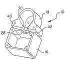
- FIG. 1is an isometric view of a housing according to an embodiment of the present invention
- FIG. 2is an isometric view of an insulating gasket according to an embodiment of the present invention
- FIG. 3Ais a front view of a smoke generating element according to an embodiment of the present invention.
- FIG. 3Bis a side view of a smoke generating element according to an embodiment of the present invention.
- FIG. 4is a cross sectional view of a smoke generating apparatus mounted to a model train according to an embodiment of the present invention
- FIG. 5is a circuit schematic of the smoke generating device according to an embodiment of the present invention.
- FIG. 6is a flow diagram illustrating the steps performed by the smoke generating device according to an embodiment of the present invention.
- FIG. 7is a graph illustrating an example of the relationship between the velocity of the fan and time
- FIG. 9is a graph illustrating the relationship between the duration of puffs of smoke and the loading on the engine.
- FIG. 10is an isometric view of a first preferred smoke generating element having a support member according to an embodiment of the present invention.
- FIG. 11is a partial cross-sectional view of the smoke generating apparatus according to an embodiment of the present invention.
- FIG. 12is an alternative embodiment of a support member according to the present invention.
- FIG. 13is a cross-sectional view of a smoke generating apparatus having a support member mounted to a model train according to an embodiment of the present invention.
- the present inventionprovides a smoke generator for a model train.
- the smoke generatorincludes a smoke generating element operably associated with a support member.
- the smoke generating elementcan be wound around the support member such that the support member acts as a core to a helix defined by the smoke generating element.
- the support membercan be used to support a substantially linear smoke generating element.
- the support membercan support substantially the entire length of the smoke generating element or a portion of the smoke generating element.
- the smoke generating elementcan be a nickel chromium wire. The nickel chromium wire is held in place with fasteners engaged with ends of the wire.
- the support elementsupports the wire, enhancing wire life and performance.
- the inventionincludes a housing 10 , a smoke generating element 12 and a blower 14 for emitting smoke from a model train 22 .
- the housing 10includes a first sub-housing 16 and a second sub-housing 18 .
- First sub-housing 16is mounted to an interior surface 20 of the model train model train 22 and houses oil used in a smoke generating process. Oil is directed through an aperture 24 of model train 22 .
- an oil burning smoke elementis shown, the invention can be practiced with any type of smoke generator and any type of smoke generating process known in the art.
- the smoke generatorcan be an ultrasonic wave nebulizer, a device for generating smoke-filled bubbles, or any other method disclosed by the references cited.
- the first sub-housing 16is shown as generally rectangular.
- First sub-housing 16can be any geometric shape, such as circular or irregularly shaped.
- the shape of first sub-housing 16can be limited only to the extent that the first sub-housing 16 is preferably mounted in the interior of model train 22 and smoke generating element 12 can be extendable into first sub-housing 16 .
- First sub-housing 16includes an opening 28 . Opening 28 of first sub-housing 16 is aligned with an opening 30 of second sub-housing 18 . Openings 28 and 30 place the first and second sub-housing 16 and 18 in fluid communication with each other. Openings 28 and 30 are shown in FIGS. 1 and 4 as generally rectangular in cross-section, however, the openings 28 and 30 can be any geometric configuration. While the first and second sub-housings 16 and 18 are shown positioned adjacent to each other, the invention can be practiced with first and second sub-housings positioned spaced apart relative to each other. A conduit can be positioned between the first and second sub-housings 16 and 18 to place the first and second sub-housings 16 and 18 in fluid communication with each other.
- Second sub-housing 18can be shaped to correspond to the shape of fan 32 .
- the second sub-housing 18is circular in shape to correspond to the squirrel cage fan 32 used in the illustrated embodiment.
- Second sub-housing 18can be shaped to conform to the style of the fan 32 selected for use in a particular embodiment of the present invention.
- second sub-housing 18can be rectangular shaped and house a squirrel cage fan 32 .
- Housing 10can be fabricated from any material having sufficient rigidity and thermal resistance. Housing 10 supports the blower 14 and the smoke generating element 12 .
- housing 10can be fabricated from aluminum, steel, cast iron, plastic, or an appropriate alloy.
- the housing 10can be fabricated from an alloy having the trade name “Zamak 3.” Zamak is a well known alloy of zinc, copper, aluminum and magnesium.
- the first and second sub-housings 16 and 18can be fabricated or formed with different materials.
- the present inventioncan also include a gasket 38 .
- Gasket 38can thermally insulate the second sub-housing 18 with respect to the first sub-housing 16 .
- Gasket 38can be advantageous to thermally insulate the blower 14 from thermal energy emitted by smoke generating element 12 .
- Gasket 38can be shaped to correspond to opposing sides 40 and 42 of first and second sub-housing 16 and 18 , respectively, of housing 10 .
- Gasket 38can be shaped in any desired geometric configuration so long as first and second sub-housings are in fluid communication with respect to each other.
- gasket 38is fabricated from silicone rubber rated to 500° F.
- smoke generating element 12includes terminals 44 a and 44 b at opposite ends of the smoke generating element 12 .
- Terminals 44 a and 44 bare shown as ringlets.
- the smoke generating elementcan be kept at a constant temperature and can be formed as a nickel chromium wire.
- the terminals 44 a and 44 bcan be integral with the nickel chromium wire of the smoke generating element 12 or can be crimped on the smoke generating element 12 .
- Smoke generating element 12can be engaged with interior surface 20 by rivets or screws or any other fastening means that can withstand the thermal energy emitted by the smoke generating element 12 .
- the smoke generating element 12is mounted to interior surface 20 of model train 22 and extends downwardly into first sub-housing 16 .
- first sub-housing 16can include a lamina 26 .
- Lamina 26is a thin plate, scale or layer made of fibrous material to absorb the oil directed into first sub-housing 16 through aperture 24 .
- Lamina 26can absorb and retain oil to be heated by the smoke generating element 12 .
- Lamina 26is operable to withstand the maximum thermal energy generated by the smoke generating element 12 .
- the second sub-housing 18is mounted to an interior surface 20 of model train 22 and houses a fan 32 of blower 14 for directing an air stream through the housing 10 .
- fan 32is a squirrel cage fan.
- fan 32can also be any type of fan including, but not limited to, an axial fan, a radial flow fan, a mixed flow fan or a cross-flow fan.
- Fan 32is positioned internally with respect to the second sub-housing 18 .
- a motor 34 for rotating the fan 32is positioned externally with respect to the second sub-housing 18 .
- the inventioncan be practiced with the fan 32 and the motor 34 positioned internally with respect to the second sub-housing 18 .
- Rotation of fan 32draws the air stream through an aperture 36 of model train 22 . While the aperture 36 is shown positioned adjacent the second sub-housing 18 , the invention can be practiced with aperture 36 positioned spaced apart from the second sub-housing 18 . A conduit can be positioned between the aperture 36 and the second sub-housing 18 , placing the aperture 36 and the second sub-housing 18 in fluid communication with respect to each other. The air stream is directed through openings 30 and 28 into first sub-housing 16 .
- Controller 46is a micro-controller operable to receive input signals and emit output signals and can be an PIC12C508 chip.
- the controller 46is in communication with the engine of the train through a serial communication line 53 including the input connector 52 .
- Serial communication line 53transmits a wide variety of information with regard to model train 22 . This information can include but is not limited to the velocity of train 22 .
- Communication between the controller 46 and the input connector 52can be enhanced with a protection resistor 66 .
- the voltage across the engine of the trainis communicated to the controller 46 with serial communication line 53 .
- the controller 46can control the operation of the motor 34 to control an airstream generated by the fan.
- the controller 46can control a rate of the airstream.
- the direction of the motor 34can be controlled by alternating the voltage across the motor 34 with an H-bridge formed with a pair of chips 60 and 62 .
- the chips 60 and 62can be XN4316 chips and can be controlled by the controller 46 .
- the velocity of the motor 34can be changed by changing the level of voltage across the motor 34 with the controller 46 .
- the circuitalso includes a voltage stabilizer defined by diode 56 , capacitor 58 and regulator 64 .
- the circuitalso includes an element 50 that can control a lamp or relay when a command is received.
- the method for generating smokebegins at step 70 .
- the loading on the trainis determined.
- the controller 46can receive input from the communication line corresponding to the loading on the engine model train.
- the loading on the model traincan correspond to a voltage across an engine of the model train or a speed at which the model train is moving.
- the controller 46can communicate with a sensor 47 engaged with a wheel 49 of the model train 22 .
- the sensor 47can sense the angular velocity of the wheel 49 and communicate the speed of the wheel 49 to the controller 46 .
- the appropriate angular velocity of the fanis determined by the controller in accordance with a control program stored in memory.
- FIG. 7an illustrative graph is provided to show movement of the fan over time to produce a puffing pattern of smoke.
- a puff of smokeis emitted from an aperture of the model train.
- the time period lasting from T 1 to T 2is the duration of a puff of smoke.
- the time period lasting from T 2 to T 3is the interval between puffs of smoke.
- the fancan be engaged at velocity V 1 in as short a period of time as possible, represented by a substantially vertical line L 1 on the graph.
- the fan 32can preferably be disengaged from velocity V 1 to zero velocity in as short a period of time as possible, represented by a substantially vertical line L 2 on the graph. More specifically the smoke unit stops the fan by temporarily reversing the current to motor. By temporarily reversing the current the fan stops abruptly thereby enhancing the puffing action of the smoke unit. As the time periods required to engage the fan up to velocity V 1 and disengage the fan 32 down from velocity V 1 decrease, a relatively more well defined puff of smoke will be emitted from the aperture of the train.
- the controllercan move the fan at a greater angular velocity, or increase the duration of puffs of smoke, or shorten the duration between puffs of smoke.
- the puffs of smokecan be generated at increasing intervals as train speed increases and can be generated at decreasing intervals as the train speed decreases.
- the puffs of smokecan be generated at increasing intervals as engine load increases and can be generated at decreasing intervals as the engine load decreases.
- more smokecan be generated as the train speed increases and less smoke can be generated as the train speed decreases.
- FIGS. 8 and 9graphs are provide to show that the time between puffs decreases as loading on the train increases. Also, the duration of individual puffs of smoke increases as loading on the engine increases.
- step 80the controller engages the motor to rotate the fan at the desired angular velocity. After the fan has been engaged at the desired velocity, the process returns to step 76 to determine loading on the engine.
- the controllercan continuously monitor the loading on the engine or can monitor the loading on the engine at predetermined intervals. For example, the controller can be operable to monitor the loading on the train every five seconds, every ten seconds or any time period desired.
- the present inventionprovides an apparatus 112 for forming smoke to be emitted by an amusement device, the apparatus comprising a support member 114 and a smoke generating element 116 having a length and an outer surface 118 , the support member 114 in contact with the smoke generating element 116 along at least part of the length and in contact with less than the entire outer surface for the at least part of the length.
- the entire length of the smoke generating element 116contacts the support member 114 at a portion 120 of the outer surface 118 of the smoke generating element 116 .
- the smoke generating element 116can be formed to extend beyond an end 124 of the support member 114 .
- the support member 114would be in contact with the smoke generating element 116 less than the entire length of the smoke generating element 116 .
- the contactoccurs at portion 120 of the outer surface. As shown in FIG. 11 , the portion 120 is less than the entire outer surface 118 .
- the smoke generating element 116is shown having a generally circular cross-section (shown elliptical in FIG. 11 due to the choice of cross-sectional plane). Portion 120 is shown as a point. However, the smoke generating element 116 can have a non-circular cross-section including a portion 120 having a predetermined width.
- a smoke generating element 116extends along a generally helical path around a support member 114 .
- Support member 114is shown having a rectangular cross-section, so the smoke generating element 116 is not a true helix.
- the smoke generating element 116can be formed in the shape of a true helix.
- Apparatus 112includes a support member 114 for supporting the smoke generating element 116 . It is believed that the position of the support member 114 relative to the smoke generating element 116 enhances and prolongs the operating life of the smoke generating element 116 .
- the support member 114has a predetermined length and can have a rectangular cross-section.
- the support member 114 acan have a circular cross-section including an aperture 126 extending the length of the support member 114 a.
- the aperture 126can be formed to extend a predetermined distance through the support member 114 a, a distance less than the length of the support member 114 a, or can be formed to extend the length of the support member 114 a.
- the support member 114can be formed having any cross-section, including an irregular geometric cross-section.
- the support member 114can be formed to have different or inconsistent cross-sections, such as partially cylindrical and partially rectangular with blending portions. In FIG.
- the support member 114is shown having a consistent, rectangular cross-section along the entire length of the support member 114 .
- the cross-section of the support member 114can be constant along the length of the support member 114 or can be variable, such as two differently-sized rectangular cross sections.
- the support member 114is shown having a constant, rectangular cross-section along the entire length of the support member 114 .
- the length and cross-section of the support member 114can be varied to enhance the resistive properties of the apparatus 112 .
- a relatively longer support member 114can support a relatively longer smoke generating element 116 having a greater resistance than a relatively shorter smoke generating element 116 .
- a relatively thicker support member 114can support a relatively longer smoke generating element 116 having a greater resistance than a relatively shorter smoke generating element 116 .
- the electrical resistance across the apparatusis 6.3 ohms, plus or minus five percent, at twenty-five (25) degrees Celsius.
- the support member 114can be fabricated from a non-conductive material capable of maintaining a rigid or semi-rigid form up to a temperature of 530° Celsius.
- the support member 114is fabricated from braided fiberglass.
- the support memberin a rectangular embodiment of the support member 114 , the support member is 3.2 millimeters wide and 0.25 millimeters thick.
- the inside diameter of the support member 114 ais 3.2 millimeters and the wall thickness is 0.25 millimeters.
- the smoke generating element 116is supported by the support member 114 along at least part of the length of the smoke generating element 116 .
- the smoke generating element 116can be a nickel chromium wire.
- the smoke generating element 116is fabricated from an alloy of 61% nickel, 15% chromium and 24% iron.
- the wireis 0.25 millimeters in diameter.
- the smoke generating element 116is in electrical communication with an electrical power source (not shown) to heat the smoke generating element 116 and burn oil or smoke fluid to form smoke.
- the smoke generating element 116can extends along a generally helical path around the support member 114 .
- the lead of the helix and the development of the helixcan be varied as desired to modify the resistance across the apparatus 112 .
- the number of turns the smoke generating element 116 completes around the support member 114 over a length of the support member 114 and the distance between adjacent turns 128 and 130can be increased or decreased to change the resistance across the smoke generating element 112 .
- the distance between turns 128 and 130can be constant along the length of the support member 114 are be varied.
- the apparatus 112can be positioned in a sub-housing 216 .
- the sub-housing 216can be positioned in a model train 222 .
- a model train 222includes an aperture 224 adjacent the apparatus 112 in the sub-housing 216 , the aperture for dispensing smoke fluid or oil in the sub-housing 216 .
- the turns of the smoke generating element 116 around the support member 114can be relatively closer at a position adjacent the aperture 224 to enhance the likelihood that smoke fluid contacts the smoke generating element 116 .
- the turnscan be spaced further apart at other positions along the length of the support member 114 where smoke fluid is unlikely to contact.
- the apparatus 112can also include at least one terminal 132 to immovably associate the support member 114 with respect to the amusement device, such as a model train 222 .
- the apparatusincludes two terminals 132 and 134 disposed at opposite ends of the support member 114 .
- the terminals 132 and 134can be fabricated from brass and can include apertures 136 and 138 , respectively, for receiving additional mounting means such as a screw, bolt, or pin 120 as shown in FIG. 13 .
- the terminals 132 and 134can be permanently connected to the support member 114 or releasibly associated.
- the terminals 132 and 134 shown in FIG. 10include projections 140 and 142 .
- the projections 140 and 142are disposed about the support member 114 .
- the projections 140 and 142can be bent or crimped around the support member 114 .
- the smoke generating element 116can be disposed between the support member 114 and either terminal 132 or 134 .
- the smoke generating element 116can be disposed between the support member 114 and the individual terminal at both ends of the support member 114 .
- the terminals 132 and 134are sufficiently wide to engage at least two turns of the smoke generating element 116 about the support member 114 as shown in FIG. 10 .
- Electric communication between the terminals 132 and 134 and the smoke generating element 116is enhanced when at least two turns of the smoke generating element 116 are in disposed between the support member 114 and the terminals 132 and 134 .
- the stability of the smoke generating element 116 with respect to the support member 114is enhanced when two turns of the smoke generating element 116 are positioned between the support element 114 and the terminals 132 or 134 .
- the first sub-housing 216can include a lamina 226 .
- Lamina 226is a thin plate, scale or layer made of fibrous material to absorb the oil directed into the first sub-housing 216 through the aperture 224 .
- Lamina 226can absorb and retain oil to be heated by the apparatus 112 .
- Lamina 226is operable to withstand the maximum thermal energy generated by the apparatus 112 .
- a second sub-housing 218is mounted to an interior surface 220 of model train 222 and houses a fan 232 of a blower 214 for directing an air stream through the sub-housing 216 .
- the fan 232is a squirrel cage fan.
- the fan 232can also be any type of fan including, but not limited to, an axial fan, a radial flow fan, a mixed flow fan or a cross-flow fan.
- Fan 232is positioned internally with respect to the second sub-housing 218 .
- a motor 234 for rotating the fan 232is positioned externally with respect to the second sub-housing 218 .
- the inventioncan be practiced with the fan 232 and the motor 234 positioned internally with respect to the second sub-housing 218 .
- Rotation of fan 232draws the air stream through an aperture 236 of model train 222 .
- the aperture 236is shown positioned adjacent the second sub-housing 218
- the inventioncan be practiced with aperture 236 positioned spaced apart from the second sub-housing 218 .
- a conduitcan be positioned between the aperture 236 and the second sub-housing 218 , placing the aperture 236 and the second sub-housing 218 in fluid communication with respect to each other.
- the air streamis directed through openings 230 and 228 into sub-housing 216 .
- a controller 246is a micro-controller operable to receive input signals and emit output signals and can be an PIC12C508 chip.
- the controller 246is in communication with the engine 248 of the train.
- the voltage across the engine of the trainis communicated to the controller 246 and, based on a program stored in memory, the controller 246 can control the operation of the motor 234 to control an airstream generated by the fan 232 .
- the controller 246can control a rate of the airstream.
- the direction of the motor 234can be controlled by alternating the voltage across the motor 234 .
- the velocity of the motor 234can be changed by changing the level of voltage across the motor 234 with the controller 246 .
- the controller 246can receive input corresponding to the loading on the engine model train.
- the loading on the model traincan correspond to a voltage across an engine of the model train or a speed at which the model train is moving.
- the controller 246can communicate with a sensor 247 engaged with a wheel 249 of the model train 222 .
- the sensor 247can sense the angular velocity of the wheel 249 and communicate the speed of the wheel 249 to the controller 246 .
- the controller 246can then control the speed of the fan 232 in response to the angular velocity of the wheel 249 detected by the sensor 247 .
Landscapes
- Toys (AREA)
Abstract
Description
Claims (21)
Priority Applications (1)
| Application Number | Priority Date | Filing Date | Title |
|---|---|---|---|
| US10/190,465US7297045B2 (en) | 2002-07-05 | 2002-07-05 | Smart smoke unit |
Applications Claiming Priority (1)
| Application Number | Priority Date | Filing Date | Title |
|---|---|---|---|
| US10/190,465US7297045B2 (en) | 2002-07-05 | 2002-07-05 | Smart smoke unit |
Publications (2)
| Publication Number | Publication Date |
|---|---|
| US20040005836A1 US20040005836A1 (en) | 2004-01-08 |
| US7297045B2true US7297045B2 (en) | 2007-11-20 |
Family
ID=29999888
Family Applications (1)
| Application Number | Title | Priority Date | Filing Date |
|---|---|---|---|
| US10/190,465Expired - Fee RelatedUS7297045B2 (en) | 2002-07-05 | 2002-07-05 | Smart smoke unit |
Country Status (1)
| Country | Link |
|---|---|
| US (1) | US7297045B2 (en) |
Cited By (13)
| Publication number | Priority date | Publication date | Assignee | Title |
|---|---|---|---|---|
| US20090212947A1 (en)* | 2008-02-26 | 2009-08-27 | Martin Professional A/S | Intruder deterrent system |
| US20090230117A1 (en)* | 2008-03-14 | 2009-09-17 | Philip Morris Usa Inc. | Electrically heated aerosol generating system and method |
| US20100015880A1 (en)* | 2008-07-15 | 2010-01-21 | Grubba Robert A | Smoke production system for model locomotive |
| WO2011007349A1 (en) | 2009-07-15 | 2011-01-20 | Yehuda Binder | Sequentially operated modules |
| WO2011016032A2 (en) | 2009-08-06 | 2011-02-10 | May Patents Ltd. | Puzzle with conductive path |
| US20120094570A1 (en)* | 2010-10-14 | 2012-04-19 | Richard James Mosher | System and method for directing smoke in a model train system |
| WO2013175269A1 (en) | 2012-05-24 | 2013-11-28 | May Patents Ltd. | System and method for a motion sensing device |
| US20150117844A1 (en)* | 2013-05-21 | 2015-04-30 | Shenzhen Boge Technology Co., Ltd | New kind of plant essential oil vaporizer |
| US9419378B2 (en) | 2011-08-26 | 2016-08-16 | Littlebits Electronics Inc. | Modular electronic building systems with magnetic interconnections and methods of using the same |
| US9545542B2 (en) | 2011-03-25 | 2017-01-17 | May Patents Ltd. | System and method for a motion sensing device which provides a visual or audible indication |
| US9597607B2 (en) | 2011-08-26 | 2017-03-21 | Littlebits Electronics Inc. | Modular electronic building systems with magnetic interconnections and methods of using the same |
| US11330714B2 (en) | 2011-08-26 | 2022-05-10 | Sphero, Inc. | Modular electronic building systems with magnetic interconnections and methods of using the same |
| US11616844B2 (en) | 2019-03-14 | 2023-03-28 | Sphero, Inc. | Modular electronic and digital building systems and methods of using the same |
Families Citing this family (1)
| Publication number | Priority date | Publication date | Assignee | Title |
|---|---|---|---|---|
| JP3744931B1 (en)* | 2004-12-28 | 2006-02-15 | 株式会社トミー | Spray toy and fog generation unit |
Citations (17)
| Publication number | Priority date | Publication date | Assignee | Title |
|---|---|---|---|---|
| US2015438A (en)* | 1932-01-26 | 1935-09-24 | Benjamin H Smith | Toy steam engine |
| DE1187165B (en)* | 1961-11-02 | 1965-02-11 | Eberhard Seuthe | Device for generating clouds of smoke by evaporating oils or the like, especially for toy locomotives |
| US3170789A (en)* | 1961-11-16 | 1965-02-23 | Owens Corning Fiberglass Corp | Nickel-base alloy |
| US3234357A (en)* | 1961-11-02 | 1966-02-08 | Seuthe Eberhard | Electrically heated smoke producing device |
| USRE26563E (en)* | 1966-12-14 | 1969-04-15 | Device to produce steam for mobile and stationary toys | |
| US3574612A (en)* | 1969-02-03 | 1971-04-13 | Atomic Energy Commission | Nickel-chromium alloy |
| US3891826A (en)* | 1972-08-05 | 1975-06-24 | Eberhard Seuthe | Electrically heated smoke or steam generator |
| DE2631639A1 (en)* | 1976-07-14 | 1978-01-19 | Seuthe Geb Timp Elisabeth | Artificial smoke prodn. in models - with multistrand glass capillaries for vaporisation of chemicals |
| US4668855A (en)* | 1984-06-19 | 1987-05-26 | Black & Decker Inc. | Supports for electric heating elements |
| JPH05106827A (en)* | 1991-10-16 | 1993-04-27 | Ricoh Co Ltd | Smoke generator |
| US5351167A (en)* | 1992-01-24 | 1994-09-27 | Pulse Engineering, Inc. | Self-leaded surface mounted rod inductor |
| US5512001A (en)* | 1995-02-03 | 1996-04-30 | Stephen Schwartz Design | Toy vehicle |
| JPH09225339A (en)* | 1996-02-26 | 1997-09-02 | Hirota Shoji:Kk | Dust collecting unit and air cleaner equipped therewith |
| WO1998030830A1 (en)* | 1997-01-06 | 1998-07-16 | Federal-Mogul Systems Protection Group Inc. | Wrappable sleeve |
| US6280278B1 (en)* | 1999-07-16 | 2001-08-28 | M.T.H. Electric Trains | Smoke generation system for model toy applications |
| US6457681B1 (en) | 2000-12-07 | 2002-10-01 | Mike's Train House, Inc. | Control, sound, and operating system for model trains |
| US6676473B2 (en)* | 2001-10-01 | 2004-01-13 | Lionel Llc | Smart smoke unit |
- 2002
- 2002-07-05USUS10/190,465patent/US7297045B2/ennot_activeExpired - Fee Related
Patent Citations (20)
| Publication number | Priority date | Publication date | Assignee | Title |
|---|---|---|---|---|
| US2015438A (en)* | 1932-01-26 | 1935-09-24 | Benjamin H Smith | Toy steam engine |
| DE1187165B (en)* | 1961-11-02 | 1965-02-11 | Eberhard Seuthe | Device for generating clouds of smoke by evaporating oils or the like, especially for toy locomotives |
| US3234357A (en)* | 1961-11-02 | 1966-02-08 | Seuthe Eberhard | Electrically heated smoke producing device |
| US3170789A (en)* | 1961-11-16 | 1965-02-23 | Owens Corning Fiberglass Corp | Nickel-base alloy |
| USRE26563E (en)* | 1966-12-14 | 1969-04-15 | Device to produce steam for mobile and stationary toys | |
| US3574612A (en)* | 1969-02-03 | 1971-04-13 | Atomic Energy Commission | Nickel-chromium alloy |
| US3891826A (en)* | 1972-08-05 | 1975-06-24 | Eberhard Seuthe | Electrically heated smoke or steam generator |
| DE2631639A1 (en)* | 1976-07-14 | 1978-01-19 | Seuthe Geb Timp Elisabeth | Artificial smoke prodn. in models - with multistrand glass capillaries for vaporisation of chemicals |
| US4668855A (en)* | 1984-06-19 | 1987-05-26 | Black & Decker Inc. | Supports for electric heating elements |
| JPH05106827A (en)* | 1991-10-16 | 1993-04-27 | Ricoh Co Ltd | Smoke generator |
| US5351167A (en)* | 1992-01-24 | 1994-09-27 | Pulse Engineering, Inc. | Self-leaded surface mounted rod inductor |
| US5512001A (en)* | 1995-02-03 | 1996-04-30 | Stephen Schwartz Design | Toy vehicle |
| JPH09225339A (en)* | 1996-02-26 | 1997-09-02 | Hirota Shoji:Kk | Dust collecting unit and air cleaner equipped therewith |
| WO1998030830A1 (en)* | 1997-01-06 | 1998-07-16 | Federal-Mogul Systems Protection Group Inc. | Wrappable sleeve |
| US6280278B1 (en)* | 1999-07-16 | 2001-08-28 | M.T.H. Electric Trains | Smoke generation system for model toy applications |
| US6457681B1 (en) | 2000-12-07 | 2002-10-01 | Mike's Train House, Inc. | Control, sound, and operating system for model trains |
| US6619594B2 (en) | 2000-12-07 | 2003-09-16 | Mike's Train House, Inc. | Control, sound, and operating system for model trains |
| US6655640B2 (en) | 2000-12-07 | 2003-12-02 | Mike's Train House, Inc. | Control, sound, and operating system for model trains |
| US6676473B2 (en)* | 2001-10-01 | 2004-01-13 | Lionel Llc | Smart smoke unit |
| US7125309B2 (en)* | 2001-10-01 | 2006-10-24 | Lionel L.L.C. | Smart smoke unit |
Non-Patent Citations (1)
| Title |
|---|
| Aerosleeves-High Performance Composites, "Fiberglass Sleeves", Internet-http://www.aerosleeves.com/order/?r=1&material=fiberglass, 2005.* |
Cited By (89)
| Publication number | Priority date | Publication date | Assignee | Title |
|---|---|---|---|---|
| US7872585B2 (en)* | 2008-02-26 | 2011-01-18 | Martin Professional A/S | Intruder deterrent system |
| US20090212947A1 (en)* | 2008-02-26 | 2009-08-27 | Martin Professional A/S | Intruder deterrent system |
| US20220125119A1 (en)* | 2008-03-14 | 2022-04-28 | Philip Morris Usa Inc. | Electrically heated aerosol generating system and method |
| US10398170B2 (en)* | 2008-03-14 | 2019-09-03 | Philip Morris Usa Inc. | Electrically heated aerosol generating system and method |
| US9848655B2 (en) | 2008-03-14 | 2017-12-26 | Philip Morris Usa Inc. | Electrically heated aerosol generating system and method |
| US11224255B2 (en)* | 2008-03-14 | 2022-01-18 | Philip Morris Usa Inc. | Electrically heated aerosol generating system and method |
| US12364289B2 (en)* | 2008-03-14 | 2025-07-22 | Philip Morris Usa Inc. | Electrically heated aerosol generating system and method |
| US20240081422A1 (en)* | 2008-03-14 | 2024-03-14 | Philip Morris Usa Inc. | Electrically heated aerosol generating system and method |
| US20090230117A1 (en)* | 2008-03-14 | 2009-09-17 | Philip Morris Usa Inc. | Electrically heated aerosol generating system and method |
| US11832654B2 (en)* | 2008-03-14 | 2023-12-05 | Philip Morris Usa Inc. | Electrically heated aerosol generating system and method |
| US9439454B2 (en)* | 2008-03-14 | 2016-09-13 | Philip Morris Usa Inc. | Electrically heated aerosol generating system and method |
| US7749040B2 (en)* | 2008-07-15 | 2010-07-06 | Grubba Robert A | Smoke production system for model locomotive |
| US20100015880A1 (en)* | 2008-07-15 | 2010-01-21 | Grubba Robert A | Smoke production system for model locomotive |
| US10864450B2 (en) | 2009-07-15 | 2020-12-15 | May Patents Ltd. | Sequentially operated modules |
| US10177568B2 (en) | 2009-07-15 | 2019-01-08 | Yehuda Binder | Sequentially operated modules |
| US12257518B2 (en) | 2009-07-15 | 2025-03-25 | May Patents Ltd. | Sequentially operated modules |
| US10447034B2 (en) | 2009-07-15 | 2019-10-15 | Yehuda Binder | Sequentially operated modules |
| WO2011007349A1 (en) | 2009-07-15 | 2011-01-20 | Yehuda Binder | Sequentially operated modules |
| US9559519B2 (en) | 2009-07-15 | 2017-01-31 | Yehuda Binder | Sequentially operated modules |
| US9583940B2 (en) | 2009-07-15 | 2017-02-28 | Yehuda Binder | Sequentially operated modules |
| US9590420B2 (en) | 2009-07-15 | 2017-03-07 | Yehuda Binder | Sequentially operated modules |
| US10396552B2 (en) | 2009-07-15 | 2019-08-27 | Yehuda Binder | Sequentially operated modules |
| US9595828B2 (en) | 2009-07-15 | 2017-03-14 | Yehuda Binder | Sequentially operated modules |
| US11383177B2 (en) | 2009-07-15 | 2022-07-12 | May Patents Ltd. | Sequentially operated modules |
| US10355476B2 (en) | 2009-07-15 | 2019-07-16 | Yehuda Binder | Sequentially operated modules |
| US9673623B2 (en) | 2009-07-15 | 2017-06-06 | Yehuda Binder | Sequentially operated modules |
| US10589183B2 (en) | 2009-07-15 | 2020-03-17 | May Patents Ltd. | Sequentially operated modules |
| US11207607B2 (en) | 2009-07-15 | 2021-12-28 | May Patents Ltd. | Sequentially operated modules |
| US11027211B2 (en) | 2009-07-15 | 2021-06-08 | May Patents Ltd. | Sequentially operated modules |
| US11014013B2 (en) | 2009-07-15 | 2021-05-25 | May Patents Ltd. | Sequentially operated modules |
| US10617964B2 (en) | 2009-07-15 | 2020-04-14 | May Patents Ltd. | Sequentially operated modules |
| US10230237B2 (en) | 2009-07-15 | 2019-03-12 | Yehuda Binder | Sequentially operated modules |
| US10981074B2 (en) | 2009-07-15 | 2021-04-20 | May Patents Ltd. | Sequentially operated modules |
| US10569181B2 (en) | 2009-07-15 | 2020-02-25 | May Patents Ltd. | Sequentially operated modules |
| US10758832B2 (en) | 2009-07-15 | 2020-09-01 | May Patents Ltd. | Sequentially operated modules |
| US9293916B2 (en) | 2009-07-15 | 2016-03-22 | Yehuda Binder | Sequentially operated modules |
| US10158227B2 (en) | 2009-07-15 | 2018-12-18 | Yehuda Binder | Sequentially operated modules |
| US10164427B2 (en) | 2009-07-15 | 2018-12-25 | Yehuda Binder | Sequentially operated modules |
| US10155153B2 (en) | 2009-08-06 | 2018-12-18 | Littlebits Electronics, Inc. | Puzzle with conductive path |
| WO2011016032A2 (en) | 2009-08-06 | 2011-02-10 | May Patents Ltd. | Puzzle with conductive path |
| US10987571B2 (en) | 2009-08-06 | 2021-04-27 | Sphero, Inc. | Puzzle with conductive path |
| US8602833B2 (en) | 2009-08-06 | 2013-12-10 | May Patents Ltd. | Puzzle with conductive path |
| US8951088B2 (en) | 2009-08-06 | 2015-02-10 | May Patents Ltd. | Puzzle with conductive path |
| US11896915B2 (en) | 2009-08-06 | 2024-02-13 | Sphero, Inc. | Puzzle with conductive path |
| US20120094570A1 (en)* | 2010-10-14 | 2012-04-19 | Richard James Mosher | System and method for directing smoke in a model train system |
| US8905809B2 (en)* | 2010-10-14 | 2014-12-09 | Lionel Llc | System and method for directing smoke in a model train system |
| US9592428B2 (en) | 2011-03-25 | 2017-03-14 | May Patents Ltd. | System and method for a motion sensing device which provides a visual or audible indication |
| US11260273B2 (en) | 2011-03-25 | 2022-03-01 | May Patents Ltd. | Device for displaying in response to a sensed motion |
| US12288992B2 (en) | 2011-03-25 | 2025-04-29 | May Patents Ltd. | Device for displaying in response to a sensed motion |
| US12249841B2 (en) | 2011-03-25 | 2025-03-11 | May Patents Ltd. | Device for displaying in response to a sensed motion |
| US9878228B2 (en) | 2011-03-25 | 2018-01-30 | May Patents Ltd. | System and method for a motion sensing device which provides a visual or audible indication |
| US9878214B2 (en) | 2011-03-25 | 2018-01-30 | May Patents Ltd. | System and method for a motion sensing device which provides a visual or audible indication |
| US10926140B2 (en) | 2011-03-25 | 2021-02-23 | May Patents Ltd. | Device for displaying in response to a sensed motion |
| US10953290B2 (en) | 2011-03-25 | 2021-03-23 | May Patents Ltd. | Device for displaying in response to a sensed motion |
| US9868034B2 (en) | 2011-03-25 | 2018-01-16 | May Patents Ltd. | System and method for a motion sensing device which provides a visual or audible indication |
| US12249842B2 (en) | 2011-03-25 | 2025-03-11 | May Patents Ltd. | Device for displaying in response to a sensed motion |
| US9808678B2 (en) | 2011-03-25 | 2017-11-07 | May Patents Ltd. | Device for displaying in respose to a sensed motion |
| US9782637B2 (en) | 2011-03-25 | 2017-10-10 | May Patents Ltd. | Motion sensing device which provides a signal in response to the sensed motion |
| US11141629B2 (en) | 2011-03-25 | 2021-10-12 | May Patents Ltd. | Device for displaying in response to a sensed motion |
| US11173353B2 (en) | 2011-03-25 | 2021-11-16 | May Patents Ltd. | Device for displaying in response to a sensed motion |
| US11192002B2 (en) | 2011-03-25 | 2021-12-07 | May Patents Ltd. | Device for displaying in response to a sensed motion |
| US9764201B2 (en) | 2011-03-25 | 2017-09-19 | May Patents Ltd. | Motion sensing device with an accelerometer and a digital display |
| US9757624B2 (en) | 2011-03-25 | 2017-09-12 | May Patents Ltd. | Motion sensing device which provides a visual indication with a wireless signal |
| US11979029B2 (en) | 2011-03-25 | 2024-05-07 | May Patents Ltd. | Device for displaying in response to a sensed motion |
| US11298593B2 (en) | 2011-03-25 | 2022-04-12 | May Patents Ltd. | Device for displaying in response to a sensed motion |
| US11305160B2 (en) | 2011-03-25 | 2022-04-19 | May Patents Ltd. | Device for displaying in response to a sensed motion |
| US9630062B2 (en) | 2011-03-25 | 2017-04-25 | May Patents Ltd. | System and method for a motion sensing device which provides a visual or audible indication |
| US10525312B2 (en) | 2011-03-25 | 2020-01-07 | May Patents Ltd. | Device for displaying in response to a sensed motion |
| US12244153B2 (en) | 2011-03-25 | 2025-03-04 | May Patents Ltd. | Device for displaying in response to a sensed motion |
| US11605977B2 (en) | 2011-03-25 | 2023-03-14 | May Patents Ltd. | Device for displaying in response to a sensed motion |
| US12191675B2 (en) | 2011-03-25 | 2025-01-07 | May Patents Ltd. | Device for displaying in response to a sensed motion |
| US11631996B2 (en) | 2011-03-25 | 2023-04-18 | May Patents Ltd. | Device for displaying in response to a sensed motion |
| US11631994B2 (en) | 2011-03-25 | 2023-04-18 | May Patents Ltd. | Device for displaying in response to a sensed motion |
| US11689055B2 (en) | 2011-03-25 | 2023-06-27 | May Patents Ltd. | System and method for a motion sensing device |
| US9555292B2 (en) | 2011-03-25 | 2017-01-31 | May Patents Ltd. | System and method for a motion sensing device which provides a visual or audible indication |
| US9545542B2 (en) | 2011-03-25 | 2017-01-17 | May Patents Ltd. | System and method for a motion sensing device which provides a visual or audible indication |
| US11916401B2 (en) | 2011-03-25 | 2024-02-27 | May Patents Ltd. | Device for displaying in response to a sensed motion |
| US12095277B2 (en) | 2011-03-25 | 2024-09-17 | May Patents Ltd. | Device for displaying in response to a sensed motion |
| US11949241B2 (en) | 2011-03-25 | 2024-04-02 | May Patents Ltd. | Device for displaying in response to a sensed motion |
| US11330714B2 (en) | 2011-08-26 | 2022-05-10 | Sphero, Inc. | Modular electronic building systems with magnetic interconnections and methods of using the same |
| US9419378B2 (en) | 2011-08-26 | 2016-08-16 | Littlebits Electronics Inc. | Modular electronic building systems with magnetic interconnections and methods of using the same |
| US9597607B2 (en) | 2011-08-26 | 2017-03-21 | Littlebits Electronics Inc. | Modular electronic building systems with magnetic interconnections and methods of using the same |
| US9831599B2 (en) | 2011-08-26 | 2017-11-28 | Littlebits Electronics Inc. | Modular electronic building systems with magnetic interconnections and methods of using the same |
| US10244630B2 (en) | 2011-08-26 | 2019-03-26 | Littlebits Electronics Inc. | Modular electronic building systems with magnetic interconnections and methods of using the same |
| US10256568B2 (en) | 2011-08-26 | 2019-04-09 | Littlebits Electronics Inc. | Modular electronic building systems with magnetic interconnections and methods of using the same |
| US12349275B2 (en) | 2011-08-26 | 2025-07-01 | Sphero, Inc. | Modular electronic building systems with magnetic interconnections and methods of using the same |
| WO2013175269A1 (en) | 2012-05-24 | 2013-11-28 | May Patents Ltd. | System and method for a motion sensing device |
| US20150117844A1 (en)* | 2013-05-21 | 2015-04-30 | Shenzhen Boge Technology Co., Ltd | New kind of plant essential oil vaporizer |
| US11616844B2 (en) | 2019-03-14 | 2023-03-28 | Sphero, Inc. | Modular electronic and digital building systems and methods of using the same |
Also Published As
| Publication number | Publication date |
|---|---|
| US20040005836A1 (en) | 2004-01-08 |
Similar Documents
| Publication | Publication Date | Title |
|---|---|---|
| US7297045B2 (en) | Smart smoke unit | |
| US6676473B2 (en) | Smart smoke unit | |
| US7412347B2 (en) | Method and apparatus for measuring physical parameters | |
| WO2016090954A1 (en) | Atomization device and electronic cigarette containing same | |
| US10001127B2 (en) | Portable DC cooling fan with simulated oscillation | |
| US7666052B2 (en) | Variable-heat smoke unit for model vehicle | |
| CN2572271Y (en) | Ultrasonic wave heating humidifier | |
| CN112369718A (en) | Lead wire and electronic atomization device | |
| US3178850A (en) | Electrical smoke generator | |
| CN211550038U (en) | Side air-out type neck hanging fan | |
| CN109917882B (en) | Heat dissipation device and terminal | |
| JPH02299603A (en) | Hair dryer | |
| WO2024230686A1 (en) | Temperature control method and system applied to aerosol generating device | |
| JPS5914733Y2 (en) | Air flow detection device | |
| US933989A (en) | Electric heater. | |
| CN222939271U (en) | Wind-finding radar and equipment with detection function | |
| JP2701275B2 (en) | Environment detection sensor for vehicle air conditioning controller | |
| WO2024230683A1 (en) | Aerosol generating device and vaping detection method therefor | |
| JPS6360289B2 (en) | ||
| JP2749350B2 (en) | Far infrared heater | |
| GB2633036A (en) | Heater assembly | |
| WO2025046502A1 (en) | Heater assembly | |
| US1108919A (en) | Heater. | |
| WO2025046374A1 (en) | Heater assembly | |
| JPS6220449B2 (en) |
Legal Events
| Date | Code | Title | Description |
|---|---|---|---|
| AS | Assignment | Owner name:LIONEL, L.L.C., MICHIGAN Free format text:ASSIGNMENT OF ASSIGNORS INTEREST;ASSIGNORS:PIERSON, MARTIN D.;ROHDE, JAMES M.;REEL/FRAME:013587/0976 Effective date:20021203 | |
| AS | Assignment | Owner name:GUGGENHEIM CORPORATE FUNDING, LLC, NEW YORK Free format text:SECURITY AGREEMENT;ASSIGNORS:LIONEL L.L.C.;LIONTECH COMPANY;REEL/FRAME:015629/0724 Effective date:20050128 | |
| AS | Assignment | Owner name:WACHOVIA BANK, NATIONAL ASSOCIATION, NEW YORK Free format text:PATENT COLLATERAL ASSIGNMENT AND SECURITY AGREEMENT;ASSIGNOR:LIONEL L.L.C.;REEL/FRAME:015667/0739 Effective date:20050128 | |
| STCF | Information on status: patent grant | Free format text:PATENTED CASE | |
| AS | Assignment | Owner name:LIONEL L.L.C., NEW YORK Free format text:RELEASE OF SECURITY INTEREST IN INTELLECTUAL PROPERTY COLLATERAL;ASSIGNOR:GUGGENHEIM CORPORATE FUNDING, LLC;REEL/FRAME:020886/0437 Effective date:20080501 Owner name:LIONTECH COMPANY, NEW YORK Free format text:RELEASE OF SECURITY INTEREST IN INTELLECTUAL PROPERTY COLLATERAL;ASSIGNOR:GUGGENHEIM CORPORATE FUNDING, LLC;REEL/FRAME:020886/0437 Effective date:20080501 | |
| AS | Assignment | Owner name:WACHOVIA BANK, NATIONAL ASSOCIATION, NEW YORK Free format text:AMENDED AND RESTATED PATENT COLLATERAL ASSIGNMENT AND SECURITY AGREEMENT;ASSIGNOR:LIONEL L.L.C.;REEL/FRAME:020909/0942 Effective date:20080501 Owner name:WACHOVIA BANK, NATIONAL ASSOCIATION,NEW YORK Free format text:AMENDED AND RESTATED PATENT COLLATERAL ASSIGNMENT AND SECURITY AGREEMENT;ASSIGNOR:LIONEL L.L.C.;REEL/FRAME:020909/0942 Effective date:20080501 | |
| AS | Assignment | Owner name:GUGGENHEIM CORPORATE FUNDING, LLC, NEW YORK Free format text:SHORT FORM PATENT SECURITY AGREEMENT;ASSIGNOR:LIONEL L.L.C.;REEL/FRAME:020951/0794 Effective date:20080501 Owner name:GUGGENHEIM CORPORATE FUNDING, LLC,NEW YORK Free format text:SHORT FORM PATENT SECURITY AGREEMENT;ASSIGNOR:LIONEL L.L.C.;REEL/FRAME:020951/0794 Effective date:20080501 | |
| AS | Assignment | Owner name:GUGGENHEIM CORPORATE FUNDING, LLC, NEW YORK Free format text:CORRECTIVE ASSIGNMENT TO CORRECT THE SIGNATURE PAGES TO THE SHORT FORM PATENT SECURITY AGREEMENT PREVIOUSLY RECORDED ON REEL 020951 FRAME 0794. ASSIGNOR(S) HEREBY CONFIRMS THE SHORT FORM PATENT SECURITY AGREEMENT.;ASSIGNOR:LIONEL L.L.C.;REEL/FRAME:021029/0775 Effective date:20080501 Owner name:GUGGENHEIM CORPORATE FUNDING, LLC, NEW YORK Free format text:CORRECTIVE ASSIGNMENT TO CORRECT THE SIGNATURE PAGES TO THE SHORT FORM PATENT SECURITY AGREEMENT PREVIOUSLY RECORDED ON REEL 020951 FRAME 0794;ASSIGNOR:LIONEL L.L.C.;REEL/FRAME:021029/0775 Effective date:20080501 Owner name:GUGGENHEIM CORPORATE FUNDING, LLC,NEW YORK Free format text:CORRECTIVE ASSIGNMENT TO CORRECT THE SIGNATURE PAGES TO THE SHORT FORM PATENT SECURITY AGREEMENT PREVIOUSLY RECORDED ON REEL 020951 FRAME 0794. ASSIGNOR(S) HEREBY CONFIRMS THE SHORT FORM PATENT SECURITY AGREEMENT;ASSIGNOR:LIONEL L.L.C.;REEL/FRAME:021029/0775 Effective date:20080501 Owner name:GUGGENHEIM CORPORATE FUNDING, LLC, NEW YORK Free format text:CORRECTIVE ASSIGNMENT TO CORRECT THE SIGNATURE PAGES TO THE SHORT FORM PATENT SECURITY AGREEMENT PREVIOUSLY RECORDED ON REEL 020951 FRAME 0794. ASSIGNOR(S) HEREBY CONFIRMS THE SHORT FORM PATENT SECURITY AGREEMENT;ASSIGNOR:LIONEL L.L.C.;REEL/FRAME:021029/0775 Effective date:20080501 | |
| FPAY | Fee payment | Year of fee payment:4 | |
| FPAY | Fee payment | Year of fee payment:8 | |
| FEPP | Fee payment procedure | Free format text:MAINTENANCE FEE REMINDER MAILED (ORIGINAL EVENT CODE: REM.); ENTITY STATUS OF PATENT OWNER: SMALL ENTITY | |
| LAPS | Lapse for failure to pay maintenance fees | Free format text:PATENT EXPIRED FOR FAILURE TO PAY MAINTENANCE FEES (ORIGINAL EVENT CODE: EXP.); ENTITY STATUS OF PATENT OWNER: SMALL ENTITY | |
| STCH | Information on status: patent discontinuation | Free format text:PATENT EXPIRED DUE TO NONPAYMENT OF MAINTENANCE FEES UNDER 37 CFR 1.362 | |
| FP | Lapsed due to failure to pay maintenance fee | Effective date:20191120 | |
| AS | Assignment | Owner name:LIONEL L.L.C., NORTH CAROLINA Free format text:RELEASE BY SECURED PARTY;ASSIGNOR:GUGGENHEIM CREDIT SERVICES, LLC (SUCCESSOR IN INTEREST TO GUGGENHEIM CORPORATE FUNDING, LLC), AS AGENT;REEL/FRAME:054246/0651 Effective date:20201026 | |
| AS | Assignment | Owner name:LIONEL L.L.C., NORTH CAROLINA Free format text:RELEASE BY SECURED PARTY;ASSIGNOR:WELLS FARGO BANK, NATIONAL ASSOCIATION;REEL/FRAME:069275/0200 Effective date:20200930 | |
| AS | Assignment | Owner name:LIONEL L.L.C., NORTH CAROLINA Free format text:RELEASE BY SECURED PARTY;ASSIGNOR:WELLS FARGO BANK, NATIONAL ASSOCIATION (AS SUCCESSOR IN INTEREST TO WACHOVIA BANK N.A.);REEL/FRAME:070770/0756 Effective date:20250407 |