US7296834B2 - Air-powered vacuum tool for handling multiple workpieces - Google Patents
Air-powered vacuum tool for handling multiple workpiecesDownload PDFInfo
- Publication number
- US7296834B2 US7296834B2US10/711,942US71194204AUS7296834B2US 7296834 B2US7296834 B2US 7296834B2US 71194204 AUS71194204 AUS 71194204AUS 7296834 B2US7296834 B2US 7296834B2
- Authority
- US
- United States
- Prior art keywords
- vacuum
- air
- powered
- ports
- workpieces
- Prior art date
- Legal status (The legal status is an assumption and is not a legal conclusion. Google has not performed a legal analysis and makes no representation as to the accuracy of the status listed.)
- Expired - Fee Related, expires
Links
- 238000012546transferMethods0.000claimsdescription6
- 238000004891communicationMethods0.000claimsdescription4
- 239000003381stabilizerSubstances0.000claimsdescription4
- 239000012530fluidSubstances0.000claimsdescription3
- 239000007788liquidSubstances0.000claims1
- 230000008901benefitEffects0.000description6
- 230000001771impaired effectEffects0.000description3
- 239000000463materialSubstances0.000description3
- 235000013361beverageNutrition0.000description2
- 235000014214soft drinkNutrition0.000description2
- XLYOFNOQVPJJNP-UHFFFAOYSA-NwaterSubstancesOXLYOFNOQVPJJNP-UHFFFAOYSA-N0.000description2
- 230000006978adaptationEffects0.000description1
- 230000004075alterationEffects0.000description1
- 238000005520cutting processMethods0.000description1
- 238000013461designMethods0.000description1
- 238000009826distributionMethods0.000description1
- 239000013536elastomeric materialSubstances0.000description1
- 238000004519manufacturing processMethods0.000description1
- 238000000034methodMethods0.000description1
- 238000012986modificationMethods0.000description1
- 230000004048modificationEffects0.000description1
- 230000008569processEffects0.000description1
- 238000012545processingMethods0.000description1
- 230000000717retained effectEffects0.000description1
- 238000003860storageMethods0.000description1
Images


Classifications
- B—PERFORMING OPERATIONS; TRANSPORTING
- B25—HAND TOOLS; PORTABLE POWER-DRIVEN TOOLS; MANIPULATORS
- B25J—MANIPULATORS; CHAMBERS PROVIDED WITH MANIPULATION DEVICES
- B25J15/00—Gripping heads and other end effectors
- B25J15/06—Gripping heads and other end effectors with vacuum or magnetic holding means
- B25J15/0616—Gripping heads and other end effectors with vacuum or magnetic holding means with vacuum
- B—PERFORMING OPERATIONS; TRANSPORTING
- B65—CONVEYING; PACKING; STORING; HANDLING THIN OR FILAMENTARY MATERIAL
- B65G—TRANSPORT OR STORAGE DEVICES, e.g. CONVEYORS FOR LOADING OR TIPPING, SHOP CONVEYOR SYSTEMS OR PNEUMATIC TUBE CONVEYORS
- B65G47/00—Article or material-handling devices associated with conveyors; Methods employing such devices
- B65G47/74—Feeding, transfer, or discharging devices of particular kinds or types
- B65G47/90—Devices for picking-up and depositing articles or materials
- B65G47/91—Devices for picking-up and depositing articles or materials incorporating pneumatic, e.g. suction, grippers
- B65G47/917—Devices for picking-up and depositing articles or materials incorporating pneumatic, e.g. suction, grippers control arrangements
Definitions
- the present inventionrelates to a material handling tool for simultaneously handling a multitude of workpieces.
- the toolis powered by vacuum generated within the tool itself.
- Vacuumhas been used to hold containers and other workpieces to end of arm tools mounted upon robot arms in the past, but such vacuum devices have not generally proven to be satisfactory because known devices generally used a single vacuum source, which if impaired, would render the entire device nonfunctional. Another problem with known vacuum devices resided in the fact that if integrity of the vacuum system were to become impaired, vacuum would be lost for the entire tool, as opposed to a portion of the tool.
- a tool according to the present inventionsolves these problems, while providing the flexibility to handle a widely differing array of workpieces, such as single serving beverage containers and packaged good of various sizes.
- An air powered vacuum tool for handling multiple workpiecesincludes a plurality of vacuum ports formed in a vacuum manifold body, and a plurality of air-powered vacuum generators operatively connected with the vacuum manifold body, such that each of the vacuum ports is provided with vacuum.
- the term “workpiece”means, without limitation, either an object which must be picked up or otherwise moved by a machine, or a food or beverage container, or a grouping of objects, such as containers, and a package containing the grouping.
- a plurality of pickup orifices adapted for engaging workpiecesis provided in a tool according to the present invention.
- Each of the pickup orificesis operatively connected with at least one of the vacuum ports.
- the vacuum portsare formed such that at least some of the ports are not in fluid communication with all others of the ports, and at least one of the vacuum ports is formed such that it is not in fluid communication with any other of the ports.
- At least one of the vacuum portsis provided with vacuum by a dedicated one of the vacuum generators which provides vacuum only to a single vacuum port.
- at least one common blow-off manifoldconducts high pressure air to more than one of the vacuum ports, which serves to expel the workpieces from the vacuum ports.
- the present air-powered vacuum toolmay be mounted upon a robot such as at the end of a robot arm, or upon a transfer machine.
- a plurality of vacuum generatorsis supplied with high pressure air by a plurality of air supply manifolds mounted to a baseplate of the vacuum tool, with the air supply manifolds being isolated so that at least some of the vacuum generators may be powered selectively.
- the vacuum portsmay be divided into a plurality of groupings.
- an air-powered vacuum toolmay be readily changed over to handle or otherwise accommodate various sizes of containers or other workpieces.
- FIG. 1is a perspective view of an air-powered vacuum tool according to the present invention including a robot arm.
- FIG. 1shows a plurality of cartons being carried by the vacuum tool.
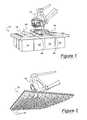
- FIG. 2is a view of the underside of an air-powered vacuum tool according to the present invention showing a plurality of container-type workpieces held thereupon.
- FIG. 3illustrates a transfer machine having an air-powered vacuum tool according to the present invention.
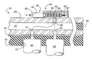
- FIG. 4is a sectional view through a portion of the base and underlying structure of the air-powered vacuum tool shown in FIGS. 1-3 .
- FIG. 5illustrates a vacuum manifold body having a plurality of vacuum ports formed therein according to an aspect of the present invention.
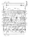
- FIG. 6is a plan view of the upper portion of an air-powered vacuum tool according to the present invention.
- air-powered vacuum tool 10is mounted upon robot arm 18 .
- the embodiment of FIGS. 1 and 2is an End of Arm Tool (“EOAT”).
- EOATEnd of Arm Tool
- FIG. 3air-powered vacuum tool 10 may be mounted upon a transfer machine, 20 .
- FIG. 1shows air-powered vacuum tool 10 as having a plurality of cartons 24 attached by vacuum thereto
- FIG. 2shows a plurality of containers 26 or other workpieces attached thereto.
- An air-powered vacuum tool according to the present inventionhas been successfully tested with 580 soft drink cans accommodated on a vacuum tool having an overall dimension of about 56 ins. by 68 ins.
- FIG. 1also shows that various components of air-powered vacuum tool 10 are mounted upon an upper portion of baseplate 28 .
- baseplate 28functions as a platform upon which various other components of the present air-powered vacuum tool may be mounted.
- mounting flange 16provides a structure for attaching the air-powered vacuum tool to a robot, or transfer machine, or other device.
- Workpiece stabilizers 90are provided at opposite ends of baseplate 28 . The purpose of workpiece stabilizers 90 is to engage stray workpieces during and immediately following a blowoff or disengagement of workpieces from vacuum tool 10 .
- Each of workpiece stabilizers 90includes a rod-like element 90 a which is pivotably attached to baseplate 28 such that elements 90 a maybe swung down to prevent loose workpieces from toppling over when they are released from vacuum tool 10 .
- FIG. 6shows many additional details of a configuration of an exemplary air-powered vacuum tool for handling multiple workpieces according to the present invention.
- high pressure airhaving a pressure in the range of 45 to 90 psi is provided by solenoid air supply valves 82 , which are electrically controlled, and which send air through a plurality of air lines 84 to multiple air supply manifolds 44 .
- Air supply manifolds 44extend laterally across baseplate 28 and are divided both longitudinally and laterally.
- a longitudinally extending bulkhead, 55divides each of air supply manifolds 44 into an air supply port, 60 , and a vacuum plenum, 62 .
- FIG. 4which also shows a vacuum generator 46 .
- the plurality of vacuum generators 46 shown in FIG. 6receives high pressure air from air supply port 60 .
- the supply airpasses through a vacuum venturi section 54 of each vacuum generator 46 , wherein a vacuum is formed. This then pulls a vacuum on vacuum plenum 62 . Thereafter, the air exits from vacuum generators 46 via outlets 56 .
- the inventors of the present inventionhave determined that an air-powered, venturi vacuum generator sold under the brand name “PIAB” and having a model designation PI12-13 is satisfactory for use in an air-powered vacuum tool according to the present invention.
- vacuum plenum 62communicates by vacuum transfer passages 66 to vacuum ports 32 which are formed in vacuum manifold body 30 .
- the vacuum manifold body, 30is abuttingly attached to the underside of baseplate 28 .
- Vacuum within vacuum ports 32is communicated by means of a plurality of vacuum supply passages 70 to a plurality of pickup orifices 72 .
- the pickup orificesare formed within workpiece interface plate 74 which is attached to the underside of baseplate 76 . It has been determined the by the inventors of the present invention that the workplace interface plate 74 may be advantageously formed by high pressure water jet forming of an elastomeric plate.
- Pickup orifices 72are shown as engaging cylindrical workpieces 80 , which may, for example, be either cylindrical containers, or bottle caps, or other cylindrical items. Because pickup orifices 72 are easily formed by cutting of workpiece interface plate 74 , the sizes and shapes of pickup orifices 72 may readily be changed to accommodate workpieces having a variety of sizes, shapes, and weights.
- each of air supply manifolds 44has a plurality of laterally extending bulkheads 58 , which serve to isolate portion of air supply manifolds 44 .
- some of vacuum ports 32 formed in vacuum manifold body 30are not interconnected and because of the use of bulkheads 58 , at least some of vacuum generators 46 may be dedicated to individual ones of vacuum ports 32 . This allows a tool according to the present invention to continue in operation if some of the vacuum generators become impaired or otherwise deactivated. For example, groupings of vacuum ports are shown at 34 , 36 , 38 , 40 and 42 , of FIG. 5 .
- Each of vacuum port groupings 34 - 42are independently controlled by means of air valves 46 a - e shown in FIG. 6 .
- vacuum generators 46 a, b, c, d and emay be shut off from the tool's air supply by de-energizing appropriate solenoid air supply valve 82 .
- vacuum manifold body 30may advantageously be formed from elastomeric material which is water jet cut in the form illustrated in FIG. 5 .
- FIG. 6additionally shows a pair of blow-off manifolds 86 which are fed by blow-off control valve 88 .
- Valve 88is attached to a source of high pressure compressed air (not shown), and feeds air through lines 89 to blow-off manifolds 86 .
- Blow-off manifolds 86are in communication with all of vacuum ports 32 - 42 , and when valve 88 is opened, the resulting rush of high pressure air will forcibly remove any workpieces which are resident in pickup orifices 72 of workpiece interface plate 74 .
- workpiece interface plate 74 and pickup orifices 72may be constructed so as to robustly engage workpieces, without having workpieces undesirably “hung up” or retained to interface plate 74 once tool 10 has come to a desired end location and all vacuum generators 46 have been shut off by means of air valves 82 .
- An air-powered vacuum tooloffers a significant advantage in terms of flexibility, as compared with fixed tooling, inasmuch as the configuration of the present tool, in terms of its capability to pick up objects of varying sizes, weights and numbers, may be easily changed by removing and replacing base 76 and workpiece interface plate 74 .
Landscapes
- Engineering & Computer Science (AREA)
- Mechanical Engineering (AREA)
- Robotics (AREA)
- Manipulator (AREA)
Abstract
Description
Claims (17)
Priority Applications (2)
| Application Number | Priority Date | Filing Date | Title |
|---|---|---|---|
| US10/711,942US7296834B2 (en) | 2004-10-14 | 2004-10-14 | Air-powered vacuum tool for handling multiple workpieces |
| CA002523448ACA2523448A1 (en) | 2004-10-14 | 2005-10-13 | Air-powered vacuum tool for handling multiple workpieces |
Applications Claiming Priority (1)
| Application Number | Priority Date | Filing Date | Title |
|---|---|---|---|
| US10/711,942US7296834B2 (en) | 2004-10-14 | 2004-10-14 | Air-powered vacuum tool for handling multiple workpieces |
Publications (2)
| Publication Number | Publication Date |
|---|---|
| US20060082172A1 US20060082172A1 (en) | 2006-04-20 |
| US7296834B2true US7296834B2 (en) | 2007-11-20 |
Family
ID=36177471
Family Applications (1)
| Application Number | Title | Priority Date | Filing Date |
|---|---|---|---|
| US10/711,942Expired - Fee RelatedUS7296834B2 (en) | 2004-10-14 | 2004-10-14 | Air-powered vacuum tool for handling multiple workpieces |
Country Status (2)
| Country | Link |
|---|---|
| US (1) | US7296834B2 (en) |
| CA (1) | CA2523448A1 (en) |
Cited By (26)
| Publication number | Priority date | Publication date | Assignee | Title |
|---|---|---|---|---|
| US20080003092A1 (en)* | 2006-06-30 | 2008-01-03 | Petar Baclija | Rotary union connection |
| US20090148258A1 (en)* | 2007-12-07 | 2009-06-11 | Chi Wah Cheng | Pick and place apparatus incorporating debris removal device |
| US20100146907A1 (en)* | 2008-11-21 | 2010-06-17 | Dematic Corp. | Stacking apparatus and method of multi-layer stacking of objects on a support |
| US20100178149A1 (en)* | 2007-04-07 | 2010-07-15 | Dematic Gmbh & Co. Kg | Process and device for multi-layer stacking on a support |
| WO2013074928A1 (en)* | 2011-11-18 | 2013-05-23 | Nike International Ltd. | Manufacturing vacuum tool |
| US20140008929A1 (en)* | 2011-03-31 | 2014-01-09 | Korea Pneumatic System Co., Ltd. | Vacuum gripper device |
| US8696043B2 (en) | 2011-11-18 | 2014-04-15 | Nike, Inc. | Hybrid pickup tool |
| US8858744B2 (en) | 2011-11-18 | 2014-10-14 | Nike, Inc. | Multi-functional manufacturing tool |
| US8958901B2 (en) | 2011-11-18 | 2015-02-17 | Nike, Inc. | Automated manufacturing of shoe parts |
| US8960745B2 (en) | 2011-11-18 | 2015-02-24 | Nike, Inc | Zoned activation manufacturing vacuum tool |
| US9010827B2 (en) | 2011-11-18 | 2015-04-21 | Nike, Inc. | Switchable plate manufacturing vacuum tool |
| US9205558B1 (en)* | 2014-07-16 | 2015-12-08 | Google Inc. | Multiple suction cup control |
| US9738462B2 (en) | 2012-07-06 | 2017-08-22 | Dematic Gmbh | Device for layered stacking a support |
| US9776812B2 (en) | 2012-07-06 | 2017-10-03 | Dematic Gmbh | Device and method for layered stacking a support |
| US9862556B2 (en) | 2012-07-06 | 2018-01-09 | Dematic Gmbh | Device for layered stacking a support |
| US10195747B1 (en)* | 2017-08-03 | 2019-02-05 | General Electric Company | Multi-faced apparatus and system for automated handling of components |
| US20190247983A1 (en)* | 2018-02-09 | 2019-08-15 | The Boeing Company | Apparatus and method for holding a workpiece |
| US10667581B2 (en) | 2011-11-18 | 2020-06-02 | Nike, Inc. | Automated identification and assembly of shoe parts |
| US20210147161A1 (en)* | 2019-11-15 | 2021-05-20 | Tyco Electronics (Shanghai) Co. Ltd. | Vacuum adsorption module |
| US11180327B2 (en) | 2017-03-29 | 2021-11-23 | Dematic Gmbh | Method for automatically stacking packages in layers on a support |
| US11235939B2 (en)* | 2017-08-10 | 2022-02-01 | Kongsberg Precision Cutting Systems Belgium Bv | Vacuum lifter |
| US11247858B2 (en)* | 2017-08-10 | 2022-02-15 | Kongsberg Precision Cutting Systems Belgium Bv | Vacuum lifter |
| US11317681B2 (en) | 2011-11-18 | 2022-05-03 | Nike, Inc. | Automated identification of shoe parts |
| US11341291B2 (en) | 2011-11-18 | 2022-05-24 | Nike, Inc. | Generation of tool paths for shoe assembly |
| US11346654B2 (en) | 2011-11-18 | 2022-05-31 | Nike, Inc. | Automated 3-D modeling of shoe parts |
| US11478942B1 (en)* | 2020-06-03 | 2022-10-25 | Amazon Technologies, Inc. | Robotic picking assemblies configured to grasp multiple items |
Families Citing this family (10)
| Publication number | Priority date | Publication date | Assignee | Title |
|---|---|---|---|---|
| US20070280812A1 (en)* | 2006-05-17 | 2007-12-06 | Axium Inc. | Tool and method for mixed palletizing/depalletizing |
| ITBO20110344A1 (en) | 2011-06-15 | 2012-12-16 | Giuseppe Gallucci | DEVICE FOR SELECTIVE PORTION OF FINISHED PORTIONS, BY CUTTING, FROM A SHEET PLACED ON A WORK PLAN |
| CN102601798B (en)* | 2012-03-15 | 2015-02-11 | 深圳市华星光电技术有限公司 | Vacuum holding device and vacuum holding method |
| JP5949799B2 (en)* | 2014-01-24 | 2016-07-13 | 株式会社安川電機 | Parallel link robot, parallel link robot hand and parallel link robot system |
| FR3017065B1 (en) | 2014-02-06 | 2016-11-18 | Coval | MODULAR VACUUM BOX |
| CN104308862B (en)* | 2014-10-21 | 2016-07-06 | 太仓思比科微电子技术有限公司 | A kind of visualization vacuum carrier |
| US11420831B2 (en)* | 2018-12-11 | 2022-08-23 | Nike, Inc. | Item pick-up system |
| DE102019110913A1 (en) | 2019-04-26 | 2020-10-29 | J. Schmalz Gmbh | Area suction cup |
| CN110394821B (en)* | 2019-07-09 | 2024-07-09 | 苏州康鸿智能装备股份有限公司 | Anti-rotation vacuum chuck device |
| CN114291577A (en)* | 2022-01-21 | 2022-04-08 | 上海卫星装备研究所 | Reflective optics sun reflector cloth sticker |
Citations (9)
| Publication number | Priority date | Publication date | Assignee | Title |
|---|---|---|---|---|
| US2572640A (en)* | 1948-08-18 | 1951-10-23 | Irving S Lovegrove | Vacuum film holder |
| US2903290A (en)* | 1954-12-09 | 1959-09-08 | American Hatchery Engineers In | Vacuum transfer machine |
| US3062578A (en)* | 1959-04-03 | 1962-11-06 | Shaffer Manufacturers Inc | Egg handling apparatus |
| US3498663A (en)* | 1967-11-29 | 1970-03-03 | Home Comfort Products Co | Adjustable vacuum platen |
| US3933388A (en)* | 1974-07-17 | 1976-01-20 | D. W. Zimmerman Mfg. Inc. | Interlock control system for a fluid-operated hoist |
| US5024575A (en)* | 1989-09-08 | 1991-06-18 | Robotic Originals, Inc. | Lightweight gripper for robotic transfer operations |
| US5387068A (en)* | 1993-12-06 | 1995-02-07 | Ford Motor Company | Method and system for loading rigid sheet material into shipping containers at a work station and end effector for use therein |
| US5609377A (en)* | 1993-12-08 | 1997-03-11 | Fuji Photo Film Co., Ltd. | Vacuum chuck apparatus |
| US6641131B2 (en)* | 2001-07-31 | 2003-11-04 | Festo Ag & Co. | Handling device, in particular for handling boards and foils |
- 2004
- 2004-10-14USUS10/711,942patent/US7296834B2/ennot_activeExpired - Fee Related
- 2005
- 2005-10-13CACA002523448Apatent/CA2523448A1/ennot_activeAbandoned
Patent Citations (9)
| Publication number | Priority date | Publication date | Assignee | Title |
|---|---|---|---|---|
| US2572640A (en)* | 1948-08-18 | 1951-10-23 | Irving S Lovegrove | Vacuum film holder |
| US2903290A (en)* | 1954-12-09 | 1959-09-08 | American Hatchery Engineers In | Vacuum transfer machine |
| US3062578A (en)* | 1959-04-03 | 1962-11-06 | Shaffer Manufacturers Inc | Egg handling apparatus |
| US3498663A (en)* | 1967-11-29 | 1970-03-03 | Home Comfort Products Co | Adjustable vacuum platen |
| US3933388A (en)* | 1974-07-17 | 1976-01-20 | D. W. Zimmerman Mfg. Inc. | Interlock control system for a fluid-operated hoist |
| US5024575A (en)* | 1989-09-08 | 1991-06-18 | Robotic Originals, Inc. | Lightweight gripper for robotic transfer operations |
| US5387068A (en)* | 1993-12-06 | 1995-02-07 | Ford Motor Company | Method and system for loading rigid sheet material into shipping containers at a work station and end effector for use therein |
| US5609377A (en)* | 1993-12-08 | 1997-03-11 | Fuji Photo Film Co., Ltd. | Vacuum chuck apparatus |
| US6641131B2 (en)* | 2001-07-31 | 2003-11-04 | Festo Ag & Co. | Handling device, in particular for handling boards and foils |
Cited By (54)
| Publication number | Priority date | Publication date | Assignee | Title |
|---|---|---|---|---|
| US20080003092A1 (en)* | 2006-06-30 | 2008-01-03 | Petar Baclija | Rotary union connection |
| US20100178149A1 (en)* | 2007-04-07 | 2010-07-15 | Dematic Gmbh & Co. Kg | Process and device for multi-layer stacking on a support |
| US20090148258A1 (en)* | 2007-12-07 | 2009-06-11 | Chi Wah Cheng | Pick and place apparatus incorporating debris removal device |
| US20100146907A1 (en)* | 2008-11-21 | 2010-06-17 | Dematic Corp. | Stacking apparatus and method of multi-layer stacking of objects on a support |
| US8468781B2 (en) | 2008-11-21 | 2013-06-25 | Dematic Corp. | Stacking apparatus and method of multi-layer stacking of objects on a support |
| US20140008929A1 (en)* | 2011-03-31 | 2014-01-09 | Korea Pneumatic System Co., Ltd. | Vacuum gripper device |
| US11273514B2 (en) | 2011-11-18 | 2022-03-15 | Nike, Inc. | Multi-functional manufacturing tool |
| US10532468B2 (en) | 2011-11-18 | 2020-01-14 | Nike, Inc. | Manufacturing vacuum tool with selective activation of pickup zones |
| US20140216662A1 (en)* | 2011-11-18 | 2014-08-07 | Nike, Inc. | Hybrid Pickup Tool |
| US8858744B2 (en) | 2011-11-18 | 2014-10-14 | Nike, Inc. | Multi-functional manufacturing tool |
| US8958901B2 (en) | 2011-11-18 | 2015-02-17 | Nike, Inc. | Automated manufacturing of shoe parts |
| US8960751B2 (en)* | 2011-11-18 | 2015-02-24 | Nike, Inc. | Hybrid pickup tool |
| US8960745B2 (en) | 2011-11-18 | 2015-02-24 | Nike, Inc | Zoned activation manufacturing vacuum tool |
| US9010827B2 (en) | 2011-11-18 | 2015-04-21 | Nike, Inc. | Switchable plate manufacturing vacuum tool |
| US12313395B2 (en) | 2011-11-18 | 2025-05-27 | Nike, Inc. | Automated 3-D modeling of shoe parts |
| US9238305B2 (en) | 2011-11-18 | 2016-01-19 | Nike, Inc. | Switchable plate manufacturing vacuum tool |
| US9403280B2 (en)* | 2011-11-18 | 2016-08-02 | Nike, Inc. | Manufacturing vacuum tool |
| TWI562875B (en)* | 2011-11-18 | 2016-12-21 | Nike Innovate Cv | Zoned activation manufacturing vacuum tool and method of operating vacuum tool |
| TWI564230B (en)* | 2011-11-18 | 2017-01-01 | 耐基創新公司 | Manufacturing vacuum tool |
| CN107030723A (en)* | 2011-11-18 | 2017-08-11 | 耐克创新有限合伙公司 | Multi-functional manufacture instrument |
| US11911893B2 (en) | 2011-11-18 | 2024-02-27 | Nike, Inc. | Manufacturing tool |
| US11879719B2 (en) | 2011-11-18 | 2024-01-23 | Nike, Inc. | Automated 3-D modeling of shoe parts |
| US11763045B2 (en) | 2011-11-18 | 2023-09-19 | Nike, Inc. | Generation of tool paths for shoe assembly |
| US9937585B2 (en) | 2011-11-18 | 2018-04-10 | Nike, Inc. | Multi-functional manufacturing tool |
| US9937627B2 (en) | 2011-11-18 | 2018-04-10 | Nike, Inc. | Manufacturing vacuum tool with selective activation of pickup zones |
| US11641911B2 (en) | 2011-11-18 | 2023-05-09 | Nike, Inc. | Automated identification and assembly of shoe parts |
| US10272518B2 (en) | 2011-11-18 | 2019-04-30 | Nike, Inc. | Multi-functional manufacturing tool |
| TWI786441B (en)* | 2011-11-18 | 2022-12-11 | 荷蘭商耐克創新有限合夥公司 | Pickup tool and method of using a pickup tool |
| TWI680090B (en)* | 2011-11-18 | 2019-12-21 | 耐克創新有限合夥公司 | Vacuum tool, pickup tool and method of using a pickup tool |
| US8696043B2 (en) | 2011-11-18 | 2014-04-15 | Nike, Inc. | Hybrid pickup tool |
| US10610958B2 (en) | 2011-11-18 | 2020-04-07 | Nike, Inc. | Multi-functional manufacturing tool |
| US10667581B2 (en) | 2011-11-18 | 2020-06-02 | Nike, Inc. | Automated identification and assembly of shoe parts |
| US10671048B2 (en) | 2011-11-18 | 2020-06-02 | Nike, Inc. | Automated manufacturing of shoe parts |
| CN107030723B (en)* | 2011-11-18 | 2020-09-08 | 耐克创新有限合伙公司 | Multifunctional manufacturing tool and method of use |
| US11422526B2 (en) | 2011-11-18 | 2022-08-23 | Nike, Inc. | Automated manufacturing of shoe parts |
| US11389972B2 (en) | 2011-11-18 | 2022-07-19 | Nike, Inc. | Manufacturing tool with selective activation of pickup zones |
| US11346654B2 (en) | 2011-11-18 | 2022-05-31 | Nike, Inc. | Automated 3-D modeling of shoe parts |
| US11341291B2 (en) | 2011-11-18 | 2022-05-24 | Nike, Inc. | Generation of tool paths for shoe assembly |
| US11317681B2 (en) | 2011-11-18 | 2022-05-03 | Nike, Inc. | Automated identification of shoe parts |
| US11266207B2 (en) | 2011-11-18 | 2022-03-08 | Nike, Inc. | Automated identification and assembly of shoe parts |
| WO2013074928A1 (en)* | 2011-11-18 | 2013-05-23 | Nike International Ltd. | Manufacturing vacuum tool |
| US9862556B2 (en) | 2012-07-06 | 2018-01-09 | Dematic Gmbh | Device for layered stacking a support |
| US9738462B2 (en) | 2012-07-06 | 2017-08-22 | Dematic Gmbh | Device for layered stacking a support |
| US9776812B2 (en) | 2012-07-06 | 2017-10-03 | Dematic Gmbh | Device and method for layered stacking a support |
| US9205558B1 (en)* | 2014-07-16 | 2015-12-08 | Google Inc. | Multiple suction cup control |
| US11180327B2 (en) | 2017-03-29 | 2021-11-23 | Dematic Gmbh | Method for automatically stacking packages in layers on a support |
| US10195747B1 (en)* | 2017-08-03 | 2019-02-05 | General Electric Company | Multi-faced apparatus and system for automated handling of components |
| US11235939B2 (en)* | 2017-08-10 | 2022-02-01 | Kongsberg Precision Cutting Systems Belgium Bv | Vacuum lifter |
| US11247858B2 (en)* | 2017-08-10 | 2022-02-15 | Kongsberg Precision Cutting Systems Belgium Bv | Vacuum lifter |
| US20190247983A1 (en)* | 2018-02-09 | 2019-08-15 | The Boeing Company | Apparatus and method for holding a workpiece |
| US10814459B2 (en)* | 2018-02-09 | 2020-10-27 | The Boeing Company | Apparatus and method for holding a workpiece |
| US11993465B2 (en)* | 2019-11-15 | 2024-05-28 | Kunshan League Automechanism Co., Ltd. | Vacuum adsorption module |
| US20210147161A1 (en)* | 2019-11-15 | 2021-05-20 | Tyco Electronics (Shanghai) Co. Ltd. | Vacuum adsorption module |
| US11478942B1 (en)* | 2020-06-03 | 2022-10-25 | Amazon Technologies, Inc. | Robotic picking assemblies configured to grasp multiple items |
Also Published As
| Publication number | Publication date |
|---|---|
| CA2523448A1 (en) | 2006-04-14 |
| US20060082172A1 (en) | 2006-04-20 |
Similar Documents
| Publication | Publication Date | Title |
|---|---|---|
| US7296834B2 (en) | Air-powered vacuum tool for handling multiple workpieces | |
| US6371717B1 (en) | Device for mechanically gripping and loading cylindrical objects | |
| US5403056A (en) | Robotic hand for transferring articles | |
| US20070119123A1 (en) | Multi-modal package handling tool and system | |
| US7409812B2 (en) | Robotic packaging device and method | |
| US8560121B2 (en) | Vacuum gripping apparatus | |
| US10865003B2 (en) | Food product handling device, system, and related methods | |
| US8286409B2 (en) | Method and apparatus, in a bottling plant, for packing beverage bottles in cases with and without dividers and a method and apparatus for packing containers in cases with and without dividers | |
| US20110030320A1 (en) | Method for closing containers by means of a closure in a gripping device | |
| US20140377049A1 (en) | Robotic container reorganizer | |
| US8011168B2 (en) | Installation for packing bottle-type objects of different designs into boxes | |
| US5385438A (en) | Method of using a robotic system for mixing and packing articles | |
| JP4634460B2 (en) | A manipulator robot device in which a lamp supports each part of the device to hold an object | |
| US7309203B2 (en) | Multi-modal container handling system | |
| JP6518212B2 (en) | Food stuffing equipment | |
| US20140119875A1 (en) | Laning Robot Systems and Methods | |
| US7574843B2 (en) | Method of manufacturing and stacking packaging units with increased stability | |
| US20130118130A1 (en) | Method and Device for Filling Containers | |
| JPWO2019004198A1 (en) | Transfer device and egg packaging system | |
| EP4146443A1 (en) | Vacuum suction apparatus | |
| CN113716111A (en) | Method and assembly for transferring products | |
| KR101748853B1 (en) | System for testing and sorting semiconductor chips | |
| US12162139B1 (en) | Gripping tool with expandable, compliant grippers, and related systems and methods | |
| US5161938A (en) | Automatic supply and loading device for sheet items | |
| EP1207125A2 (en) | Pickup head for pallet unloading machines |
Legal Events
| Date | Code | Title | Description |
|---|---|---|---|
| AS | Assignment | Owner name:AIDCO INTERNATIONAL, INC., MICHIGAN Free format text:ASSIGNMENT OF ASSIGNORS INTEREST;ASSIGNORS:CLARK, JEFFREY A.;FRANK, WILLIAM A.;HARRINGTON, RICHARD M.;AND OTHERS;REEL/FRAME:015243/0265;SIGNING DATES FROM 20041004 TO 20041005 | |
| AS | Assignment | Owner name:AIDCO INTERNATIONAL, INC., MICHIGAN Free format text:ASSIGNMENT OF ASSIGNORS INTEREST;ASSIGNORS:CLARK, JEFFREY A.;FRANK, WILLIAM A.;HARRINGTON, RICHARD M.;AND OTHERS;REEL/FRAME:016886/0046;SIGNING DATES FROM 20041004 TO 20041005 | |
| CC | Certificate of correction | ||
| FEPP | Fee payment procedure | Free format text:PAT HOLDER CLAIMS SMALL ENTITY STATUS, ENTITY STATUS SET TO SMALL (ORIGINAL EVENT CODE: LTOS); ENTITY STATUS OF PATENT OWNER: SMALL ENTITY | |
| AS | Assignment | Owner name:PALLIGISTICS LLC, OHIO Free format text:ASSIGNMENT OF ASSIGNORS INTEREST;ASSIGNOR:AIDCO INTERNATIONAL, INC.;REEL/FRAME:025503/0054 Effective date:20100410 | |
| REMI | Maintenance fee reminder mailed | ||
| FPAY | Fee payment | Year of fee payment:4 | |
| SULP | Surcharge for late payment | ||
| AS | Assignment | Owner name:TRAVELERS CASUALTY AND SURETY COMPANY OF AMERICA, Free format text:SECURITY AGREEMENT;ASSIGNOR:PALLIGISTICS LLC;REEL/FRAME:027456/0329 Effective date:20110325 | |
| AS | Assignment | Owner name:PALLIGISTICS LLC, OHIO Free format text:RELEASE OF SECURITY AGREEMENT;ASSIGNOR:TRAVELERS CASUALTY AND SURETY COMPANY OF AMERICA;REEL/FRAME:029597/0271 Effective date:20130109 | |
| AS | Assignment | Owner name:PREMIER TECH TECHNOLOGIES LTD, CANADA Free format text:ASSIGNMENT OF ASSIGNORS INTEREST;ASSIGNOR:PALLIGISTICS LLC;REEL/FRAME:029948/0895 Effective date:20130228 | |
| REMI | Maintenance fee reminder mailed | ||
| LAPS | Lapse for failure to pay maintenance fees | ||
| STCH | Information on status: patent discontinuation | Free format text:PATENT EXPIRED DUE TO NONPAYMENT OF MAINTENANCE FEES UNDER 37 CFR 1.362 | |
| FP | Lapsed due to failure to pay maintenance fee | Effective date:20151120 | |
| AS | Assignment | Owner name:CANADIAN IMPERIAL BANK OF COMMERCE, CANADA Free format text:SECURITY INTEREST;ASSIGNORS:PREMIER TECH LTD. / PREMIER TECH LTEE;PREMIER TECH HOME & GARDEN INC.;PREMIER HORTICULTURE LTD. / PREMIER HORTICULTURE LTEE;AND OTHERS;REEL/FRAME:059726/0620 Effective date:20220406 |