US7295881B2 - Nerve-branch-specific action-potential activation, inhibition, and monitoring - Google Patents
Nerve-branch-specific action-potential activation, inhibition, and monitoringDownload PDFInfo
- Publication number
- US7295881B2 US7295881B2US10/745,514US74551403AUS7295881B2US 7295881 B2US7295881 B2US 7295881B2US 74551403 AUS74551403 AUS 74551403AUS 7295881 B2US7295881 B2US 7295881B2
- Authority
- US
- United States
- Prior art keywords
- nerve
- action potential
- branch
- potential propagations
- generating
- Prior art date
- Legal status (The legal status is an assumption and is not a legal conclusion. Google has not performed a legal analysis and makes no representation as to the accuracy of the status listed.)
- Expired - Lifetime, expires
Links
- 230000036982action potentialEffects0.000titleclaimsabstractdescription222
- 238000012544monitoring processMethods0.000titleabstractdescription43
- 230000004913activationEffects0.000titledescription29
- 230000005764inhibitory processEffects0.000titledescription8
- 210000005036nerveAnatomy0.000claimsabstractdescription214
- 210000004126nerve fiberAnatomy0.000claimsabstractdescription77
- 238000004891communicationMethods0.000claimsabstractdescription21
- 210000004556brainAnatomy0.000claimsabstractdescription12
- 230000009977dual effectEffects0.000claimsabstractdescription11
- 238000000034methodMethods0.000claimsdescription53
- 230000003213activating effectEffects0.000claimsdescription43
- 210000001186vagus nerveAnatomy0.000claimsdescription14
- 230000000747cardiac effectEffects0.000claimsdescription8
- 230000002496gastric effectEffects0.000claimsdescription6
- 125000006850spacer groupChemical group0.000claimsdescription5
- 229910052751metalInorganic materials0.000claimsdescription4
- 239000002184metalSubstances0.000claimsdescription4
- 239000002253acidSubstances0.000claimsdescription3
- 230000003321amplificationEffects0.000claimsdescription3
- 230000000968intestinal effectEffects0.000claimsdescription3
- 238000003199nucleic acid amplification methodMethods0.000claimsdescription3
- 230000017531blood circulationEffects0.000claimsdescription2
- 210000003899penisAnatomy0.000claimsdescription2
- 210000000115thoracic cavityAnatomy0.000claimsdescription2
- 208000034347Faecal incontinenceDiseases0.000claims1
- 239000012777electrically insulating materialSubstances0.000claims1
- 230000002401inhibitory effectEffects0.000abstractdescription49
- 239000000835fiberSubstances0.000description45
- 210000000056organAnatomy0.000description39
- 230000000638stimulationEffects0.000description23
- 230000000903blocking effectEffects0.000description22
- 230000000694effectsEffects0.000description21
- 230000006870functionEffects0.000description17
- 210000002216heartAnatomy0.000description14
- 210000003050axonAnatomy0.000description13
- 230000001902propagating effectEffects0.000description11
- 230000036279refractory periodEffects0.000description11
- 210000001519tissueAnatomy0.000description11
- 210000004027cellAnatomy0.000description9
- 239000012528membraneSubstances0.000description9
- 210000002569neuronAnatomy0.000description9
- 238000013461designMethods0.000description7
- 210000003205muscleAnatomy0.000description7
- 230000007383nerve stimulationEffects0.000description7
- 230000000644propagated effectEffects0.000description7
- 210000001170unmyelinated nerve fiberAnatomy0.000description7
- 230000002102hyperpolarizationEffects0.000description6
- 239000000463materialSubstances0.000description6
- 230000001953sensory effectEffects0.000description6
- 210000000038chestAnatomy0.000description5
- 229910001415sodium ionInorganic materials0.000description5
- 210000002784stomachAnatomy0.000description5
- 230000000875corresponding effectEffects0.000description4
- 229940079593drugDrugs0.000description4
- 239000003814drugSubstances0.000description4
- 210000000170cell membraneAnatomy0.000description3
- 210000003169central nervous systemAnatomy0.000description3
- 230000001934delayEffects0.000description3
- 210000000268efferent neuronAnatomy0.000description3
- 238000002513implantationMethods0.000description3
- 230000001939inductive effectEffects0.000description3
- 210000000936intestineAnatomy0.000description3
- 230000000670limiting effectEffects0.000description3
- 230000028161membrane depolarizationEffects0.000description3
- 230000025350membrane depolarization involved in regulation of action potentialEffects0.000description3
- 210000003666myelinated nerve fiberAnatomy0.000description3
- 230000002441reversible effectEffects0.000description3
- 230000004936stimulating effectEffects0.000description3
- 241000282326Felis catusSpecies0.000description2
- 206010021118HypotoniaDiseases0.000description2
- 206010021639IncontinenceDiseases0.000description2
- 206010028813NauseaDiseases0.000description2
- 241000283973Oryctolagus cuniculusSpecies0.000description2
- 241000700159RattusSpecies0.000description2
- 206010047700VomitingDiseases0.000description2
- 230000003187abdominal effectEffects0.000description2
- 230000009471actionEffects0.000description2
- 230000001154acute effectEffects0.000description2
- 210000003766afferent neuronAnatomy0.000description2
- 238000004458analytical methodMethods0.000description2
- 230000005540biological transmissionEffects0.000description2
- 230000008602contractionEffects0.000description2
- 230000001276controlling effectEffects0.000description2
- 208000037265diseases, disorders, signs and symptomsDiseases0.000description2
- 208000035475disorderDiseases0.000description2
- 230000002550fecal effectEffects0.000description2
- 230000000762glandularEffects0.000description2
- 208000002551irritable bowel syndromeDiseases0.000description2
- 238000012986modificationMethods0.000description2
- 230000004048modificationEffects0.000description2
- 230000004899motilityEffects0.000description2
- 230000003387muscularEffects0.000description2
- 230000008693nauseaEffects0.000description2
- 230000023533negative regulation of action potentialEffects0.000description2
- 210000000944nerve tissueAnatomy0.000description2
- 210000000653nervous systemAnatomy0.000description2
- 230000008058pain sensationEffects0.000description2
- 210000000578peripheral nerveAnatomy0.000description2
- BASFCYQUMIYNBI-UHFFFAOYSA-NplatinumChemical compound[Pt]BASFCYQUMIYNBI-UHFFFAOYSA-N0.000description2
- 229910001414potassium ionInorganic materials0.000description2
- 230000002336repolarizationEffects0.000description2
- 230000004044responseEffects0.000description2
- 230000000284resting effectEffects0.000description2
- 230000035945sensitivityEffects0.000description2
- 239000011734sodiumSubstances0.000description2
- 230000001629suppressionEffects0.000description2
- 230000005641tunnelingEffects0.000description2
- 230000008673vomitingEffects0.000description2
- 206010010774ConstipationDiseases0.000description1
- 206010011224CoughDiseases0.000description1
- 244000043261Hevea brasiliensisSpecies0.000description1
- 239000000232Lipid BilayerSubstances0.000description1
- 102000004895LipoproteinsHuman genes0.000description1
- 108090001030LipoproteinsProteins0.000description1
- 241001465754MetazoaSpecies0.000description1
- 102000006386Myelin ProteinsHuman genes0.000description1
- 108010083674Myelin ProteinsProteins0.000description1
- 229910003251Na KInorganic materials0.000description1
- RTAQQCXQSZGOHL-UHFFFAOYSA-NTitaniumChemical compound[Ti]RTAQQCXQSZGOHL-UHFFFAOYSA-N0.000description1
- 230000036528appetiteEffects0.000description1
- 235000019789appetiteNutrition0.000description1
- 230000002567autonomic effectEffects0.000description1
- 230000008901benefitEffects0.000description1
- 210000005056cell bodyAnatomy0.000description1
- 230000008859changeEffects0.000description1
- 238000010276constructionMethods0.000description1
- 210000001787dendriteAnatomy0.000description1
- 230000001419dependent effectEffects0.000description1
- 201000006549dyspepsiaDiseases0.000description1
- 238000005516engineering processMethods0.000description1
- 238000011156evaluationMethods0.000description1
- 210000004907glandAnatomy0.000description1
- PCHJSUWPFVWCPO-UHFFFAOYSA-NgoldChemical compound[Au]PCHJSUWPFVWCPO-UHFFFAOYSA-N0.000description1
- 229910052737goldInorganic materials0.000description1
- 239000010931goldSubstances0.000description1
- 239000007943implantSubstances0.000description1
- 201000001881impotenceDiseases0.000description1
- 238000002347injectionMethods0.000description1
- 239000007924injectionSubstances0.000description1
- 238000009413insulationMethods0.000description1
- 210000002977intracellular fluidAnatomy0.000description1
- 150000002500ionsChemical class0.000description1
- 229910052741iridiumInorganic materials0.000description1
- GKOZUEZYRPOHIO-UHFFFAOYSA-Niridium atomChemical compound[Ir]GKOZUEZYRPOHIO-UHFFFAOYSA-N0.000description1
- 210000000867larynxAnatomy0.000description1
- 210000004185liverAnatomy0.000description1
- 210000004072lungAnatomy0.000description1
- 230000007246mechanismEffects0.000description1
- 210000002161motor neuronAnatomy0.000description1
- 230000004118muscle contractionEffects0.000description1
- 210000005012myelinAnatomy0.000description1
- 229920003052natural elastomerPolymers0.000description1
- 229920001194natural rubberPolymers0.000description1
- 230000036961partial effectEffects0.000description1
- 210000003800pharynxAnatomy0.000description1
- 230000004962physiological conditionEffects0.000description1
- 229910052697platinumInorganic materials0.000description1
- 230000017934positive regulation of action potentialEffects0.000description1
- BITYAPCSNKJESK-UHFFFAOYSA-NpotassiosodiumChemical compound[Na].[K]BITYAPCSNKJESK-UHFFFAOYSA-N0.000description1
- 230000008569processEffects0.000description1
- 238000012545processingMethods0.000description1
- 238000011555rabbit modelMethods0.000description1
- 230000007115recruitmentEffects0.000description1
- 230000002829reductive effectEffects0.000description1
- 238000011160researchMethods0.000description1
- 210000002955secretory cellAnatomy0.000description1
- 229910052710siliconInorganic materials0.000description1
- 239000010703siliconSubstances0.000description1
- 210000002027skeletal muscleAnatomy0.000description1
- 230000000392somatic effectEffects0.000description1
- 210000000278spinal cordAnatomy0.000description1
- 229910001220stainless steelInorganic materials0.000description1
- 239000010935stainless steelSubstances0.000description1
- 239000000126substanceSubstances0.000description1
- 229910052715tantalumInorganic materials0.000description1
- GUVRBAGPIYLISA-UHFFFAOYSA-Ntantalum atomChemical compound[Ta]GUVRBAGPIYLISA-UHFFFAOYSA-N0.000description1
- 238000012360testing methodMethods0.000description1
- 229910052719titaniumInorganic materials0.000description1
- 239000010936titaniumSubstances0.000description1
- 238000002604ultrasonographyMethods0.000description1
- 210000004291uterusAnatomy0.000description1
- 210000004760visceral afferentAnatomy0.000description1
Images


Classifications
- A—HUMAN NECESSITIES
- A61—MEDICAL OR VETERINARY SCIENCE; HYGIENE
- A61N—ELECTROTHERAPY; MAGNETOTHERAPY; RADIATION THERAPY; ULTRASOUND THERAPY
- A61N1/00—Electrotherapy; Circuits therefor
- A61N1/02—Details
- A61N1/04—Electrodes
- A61N1/05—Electrodes for implantation or insertion into the body, e.g. heart electrode
- A61N1/0551—Spinal or peripheral nerve electrodes
- A61N1/0556—Cuff electrodes
Definitions
- the present inventionrelates to nerve stimuli, and more particularly, to apparatus and methods for nerve-branch-specific action-potential activation, inhibition, and monitoring.
- the nervous systemis a network of billions of interconnected nerve cells, or neurons, that receive various types of stimuli and cause the body to respond appropriately.
- the neuronslink the central nervous system (CNS) consisting of the brain and the spinal cord, with the body.
- CNScentral nervous system
- a neuronusually has a cell body, dendrites that receive inputs, and an axon, an elongated nerve fiber that transmits electrical potentials as action potential.
- Efferent neuronssend impulses peripherally to activate muscles or secretory cells, while afferent neurons convey sensory information centrally from the periphery.
- the axonthe fiber-like, elongated portion of the nerve cell, conducts impulses in two directions, to and from the body of the nerve cell and transmits the information along the nervous system. Its function is somewhat analogous to a wire in an electric circuit. However, whereas in an electrical circuit, a wire allows the passage of a current, generally along its core, the axon, on the other hand, operates by the propagation of a potential difference along its plasma-membrane external surface, formed as a molecular lipid bilayer.
- the propagating potential differenceis referred to as action potential. It is an “all-or-nothing” phenomenon, described below:
- Rest ConditionWhen at rest, sodium-potassium pumps in the plasma membrane keep a higher concentration of sodium ions outside the cell and a higher concentration of potassium ions inside, and create a voltage difference, of about 60-100 mV, generally referred to as the resting potential. Since the external surface is positive and the internal surface is negative, the membrane is polarized.
- DepolarizationWhen the neuron is stimulated, a small region of the cell's membrane is depolarized to a threshold potential. When this happens, voltage-gated Na channels along the membrane open, and Na + ions rapidly diffuse into the cell, causing the electrical potential across the cell membrane to be reduced. As Na + ions continue to diffuse into the cell, an excess of positive ions accumulates inside, and the membrane becomes positively charged inside and negatively charged outside, at that small region. The action potential that is formed is typically about 20 mV. The voltage-gated Na channels then spontaneously close.
- PropagationThe negatively charged membrane at the small region of the action potential stimulates the adjacent region to become depolarized. Thus the action potential propagates as a wave.
- RepolarizationBy the time the action potential has moved from one small region along the membrane to the adjacent region, the first region has repolarized and returned to its resting potential. Repolarization occurs as the Na + channels close and K + channels open, allowing K + ions to diffuse out of the cell more rapidly, restoring the positive charge to the external surface of the membrane, and the negative charge to the internal surface.
- the Refractory Periodis defined as the time period when an excitable membrane cannot be stimulated. It prevents the action potential from stimulating the region from which it came. In other words, it prevents reverberation between two adjacent regions. Thus, propagation must continue forward.
- Na + ionsare actively transported out of and K + into the cell by the Na—K pumps.
- the refractory periodcan be divided into two distinct portions:
- phase propagation processis very rapid, about 3 msec to a region, in myelinated fibers. Neurons typically fire at rates of 100 action potentials per second.
- conductionis non-decremental, that is, it does not diminish, or ‘die out’ with distance from the initial site of stimulation. This is in marked contrast to conduction in a wire of an electrical circuit.
- Neuronsmay be classified by conduction speed, diameter and the presence or absence of specialized lipoprotein insulation called myelin.
- the main nerve fibersof about 2-20 microns in diameter, are myelinated, while the lower branches, down to about 0.2 microns in diameter, are unmyelinated.
- myelinated fibersconduction is saltatory, or by jumps, along the unmeylinated nodes of Ranvier.
- unmyelinated nerve fibersconduction is smooth.
- Type A fibersare myelinated and can conduct impulses at 12-120 m/sec.
- Type Bare also myelinated fibers but they only transmit impulses at 3-5 m/sec.
- Type C fibersare unmyelinated, small in diameter, and their conduction is very slow, at a rate of about 0.2-2.0 m/sec.
- An example of a Type A fiberis a motor efferent neuron innervating the gastrocnemius.
- An example of a Type B fiberis an autonomic preganglionic efferent neuron.
- An example of a Type C fiberis a sensory afferent neuron carrying information about diffused pain.
- the refractory period of action-potential propagationmakes nerve blocking possible.
- a number of blocking techniquesare presently known for blocking or stimulating motor nerves controlling muscular or glandular activities. These include: (1) collision block; (2) high frequency block; and (3) anodal block.
- high frequency (e.g., 600 Hz) stimulationsare used to block the transmission of the action potentials through the nerve fibers.
- nerve fibersare locally hyperpolarized by a DC anodal current. If sufficiently hyperpolarized, action potentials are not able to propagate through the hyperpolarized zone and will be blocked.
- Anodal blockis described, for example, in N. J. M. Rijkhof et al., “Acute Animal Studies on the Use of Anodal Block to Reduce Urethral Resistance in Sacral Root Stimulation” IEEE Transactions on Rehabilitation Engineering, Vol. 2, No. 2, pp. 92, 1994, whose disclosure is incorporated herein by reference.
- artificially induced action potentialsare generated by a unidirectional electrode (an electrode adapted for generating an action-potential propagation substantially in one direction) and collide with, and thereby block, the naturally induced action potentials, coming towards them.
- the artificially induced action potential at a region along the axon membraneis timed and shaped so that when a naturally induced action potential arrives at that region, the region is in a refractory period, and the naturally induced action potential cannot propagate through it.
- Collision blockhas been described, for example, in C. van den Honert, J. T. Mortimer “A Technique for Collision Blocks of Peripheral Nerve: Single Stimulus Analysis”, IEEE Transactions on Biomedical Engineering, Vol. 28, No. 5, pp 373, 1981, whose disclosure is incorporated herein by reference.
- the unidirectional electrodeis an important component in collision blocking. Designs of unidirectional electrodes may be found, for example, in the following articles, Ungar I J et al., “Generation of unidirectionally propagating action potentials using a monopolar electrode cuff,” Annals of Biomedical Engineering, 14:437-450 (1986), Sweeney J D et al., “An asymmetric two electrode cuff for generation of unidirectionally propagated action potentials,” IEEE Transactions on Biomedical Engineering, vol.
- the electrode cuffincludes a dielectric sleeve in which the cathode is positioned a first distance from an escape end and a second distance from an arrest end.
- the first distanceis at least 1.7, and preferably about 7, times the second distance. This asymmetry causes a primary or forward stimulus signal current to be correspondingly greater than a secondary or reverse current.
- the electrode cuffincludes an annular cathode having a circular passage therethrough of a first diameter.
- An annular anodehas a larger circular passage therethrough of a second diameter, which second diameter is about 1.2 to 3.0 times the first diameter.
- a non-conductive sheathextends around the anode, cathode, and nerve trunk.
- the anode and cathodeare placed asymmetrically to one side of the non-conductive sheath.
- a first length along the electrode sheath between a first end and the cathodeis at least twice a second length between the anode and cathode.
- a third length between the anode and a second end of the conductive sheathis smaller than the first or second lengths.
- Selective blockingrelies on some combination of these techniques, for example, using a tripolar electrode formed as a cathode and primary and secondary anodes.
- nerve stimulationis performed with the cathode.
- fibers of lower diametersare “recruited,” or stimulated.
- both A and B fibersare activated.
- the currentis divided between the primary and secondary anodes, such that while the cathode operates at a current that activate both A and B fibers, the primary anode inhibits A fibers, by hyper-polarization tuned specifically for these larger-diameter fibers.
- an overall activation of B fibersis achieved, with the action potential propagation in the B fibers being towards the secondary anode. In this manner it is possible to predefine a range of nerve-fiber diameters and activate them specifically.
- the tripolar electrode used for muscle controlincludes a central cathode flanked on its opposite sides by two anodes.
- the central cathodegenerates action potentials in the motor nerve fiber by cathodic stimulation; one anode produces a complete anodal block in one direction so that the action potential produced by the cathode is unidirectional; and the other anode produces a selective anodal block to permit passage of the action potential in the opposite direction through selected motor nerve fibers to produce the desired muscle stimulation or suppression.
- the described preferred embodimentsthere are a plurality of electrode devices spaced along the length of the nerve bundle which are sequentially actuated with delays corresponding to the velocity of propagation of the body-generated action potentials through the large-diameter fibers to produce a “green wave” effect which minimizes undesired anodal blocking of the large-diameter fibers while maximizing the collision blocking of the small-diameter fibers.
- An electrode deviceis adapted to be coupled to longitudinal nervous tissue of the subject, and a control unit is adapted to drive the electrode device to apply to the nervous tissue a current, which is capable of inducing action potentials that propagate in the nervous tissue in a first direction, so as to treat the condition.
- the control unitis further adapted to suppress action potentials from propagating in the nervous tissue in a second direction opposite to the first direction.
- a problem with nerve activationis a “virtual cathode effect,” or a “virtual anode effect,” which causes some interference, as follows:
- the activation functionis the second spatial derivative of the electric potential along an axon. In the region where the activation function is positive, the axon depolarizes, and in the region where the activation function is negative, the axon hyperpolarizes. If the activation function is sufficiently positive, then the depolarization will cause the axon to generate an action potential; similarly, if the activation function is sufficiently negative, then local blocking of action potentials transmission occurs.
- the activation functiondepends on the current applied, as well as the geometry of the electrodes and of the axon.
- Uis the potential
- ⁇is the conductance tensor specifying the conductance of the various materials (electrode housing, axon, intracellular fluid, etc.)
- jis a scalar function representing the current source density specifying the locations of current injection.
- the activation functionis found by solving this partial differential equation for U. If the axon is defined to lie in the z direction, then the activation function is:
- US Patent Application 20030050677to Gross, et al., entitled, “Electrode assembly for nerve control,” whose disclosure is incorporated herein by reference, describes an apparatus for applying current to a nerve, the apparatus being designed also to reduce the virtual cathode effect.
- a cathodeis adapted to be placed in a vicinity of a cathodic longitudinal site of the nerve and to apply a cathodic current to the nerve.
- a primary inhibiting anodeis adapted to be placed in a vicinity of a primary anodal longitudinal site of the nerve and to apply a primary anodal current to the nerve.
- a secondary inhibiting anodeis adapted to be placed in a vicinity of a secondary anodal longitudinal site of the nerve and to apply a secondary anodal current to the nerve, the secondary anodal longitudinal site being closer to the primary anodal longitudinal site than to the cathodic longitudinal site.
- the secondary anodal currentis of lower magnitude than the primary anodal current.
- the virtual cathode effectcan stimulate, rather than block, the generation of action potentials in fibers in a region adjacent to the application of anodal current of a sufficiently high magnitude.
- the apparatus of US Patent Application 20030050677may include a housing to which the cathode and a plurality of anodes are coupled, wherein one of the anodes is positioned within the housing so as to reduce a virtual cathode effect induced by another one of the anodes.
- the Vagus nerve(the tenth cranial nerve) has been the subject of considerable research in nerve stimulation. It is composed of somatic and visceral afferents and efferents, and is responsible for controlling and (or) receiving feedback from various glands, the pharynx, larynx, heart, lungs, liver, stomach, intestine, and uterus. Because of its large number of functions with respect to a range of body systems, the Vagus nerve is preferred in many applications for purposes of modulating the functions of designated organs or portions of the central nervous system.
- Nerve blocking along a major nerve trunk such as the Vagus nervemay be achieved by implanting an electrode along the trunk, which is large enough, and visible. Yet, such blocking affects the large plurality of nerve branches that emerge from the trunk, and their respective organs, without discrimination. However, in general, discrimination is important, and it is generally desired to target only a specific organ. Because the nerve fibers leading to the specific organs are very fine, implanting an electrode along it is technically difficult. There is thus a need for activating, inhibiting, and monitoring action-potential propagations along a specific nerve branch, with minimum interference to other nerve branches.
- a dual electrode arrangementfor nerve-branch-specific, action-potential association, comprising:
- the proximal electrode configurationis a cathode, adapted to generate an action-potential propagation
- the distal electrode configurationis an anode, adapted to block an action potential propagation, by hyperpolarization
- the electrode configurationsinclude spacers for preventing direct contact between a metal and a nerve tissue.
- the proximal and distal electrode configurationsare unidirectional electrode configurations, each adapted for generating an action-potential propagation substantially in one direction, the unidirectional electrode configurations being arranged as mirror images to each other, so that the generated action-potential propagations are towards each other.
- the unidirectional electrode configurationsare monopolar, unidirectional electrode configurations.
- the unidirectional electrode configurationsare bipolar, unidirectional electrode configurations.
- the unidirectional electrode configurationsare tripolar, unidirectional electrode configurations.
- the unidirectional electrode configurationsare multipart, unidirectional electrode configurations.
- the nerve-branch-specific, action-potential associationis selected from the group consisting of:
- an apparatusfor nerve-branch-specific, action-potential association, comprising:
- a dual electrode arrangementwhich comprises:
- the electronic unitcomprises a controller.
- the electronic unitcomprises a sensor unit, in communication with the controller.
- the electronic unitcomprises a pulse generator.
- the electronic unitcomprises an amplification component.
- the electronic unitcomprises a receiver.
- the electronic unitcomprises a transmitter.
- the unidirectional electrode configurationsare activated by a stimulation current which is no greater than 20 mA.
- a method for nerve-branch-specific, action-potential associationcomprising:
- a proximal electrode configurationon a nerve trunk, proximally to a junction of the nerve trunk with a preselected nerve branch;
- the proximal and distal electrode configurationsare unidirectional electrode configurations, arranged as mirror images to each other, so that the generated action-potential propagations are towards each other.
- the methodcomprises generating efferent action-potential propagations, substantially restricted to the preselected nerve branch.
- the methodcomprises inhibiting afferent action-potential propagations, from the preselected nerve branch.
- the methodcomprises selectively generating action-potential propagations, in a subset of nerve fibers of a predetermined diameter range, substantially restricted to the preselected nerve branch.
- the methodcomprises selectively inhibiting action-potential propagations, in a subset of nerve fibers of a predetermined diameter range, substantially restricted to the preselected nerve branch.
- the methodcomprises monitoring naturally-occurring, efferent action-potential propagations, heading towards the preselected nerve branch.
- the methodcomprises monitoring naturally-occurring, afferent action-potential propagations, from the preselected nerve branch.
- the methodcomprises activating the electrode configurations in accordance with a predetermined schedule.
- the methodcomprises activating the electrode configurations simultaneously.
- a set of unidirectional electrodeslocated around a nerve branch, configured to generate action-potential propagations only in the nerve branch.
- the set of unidirectional electrodesis configured to generate action-potential propagations in the nerve branch, to affect an organ.
- the set of unidirectional electrodesis configured to block afferent action potential originating from an organ.
- the set of unidirectional electrodesis configured to selective activate and block action potential associated with the nerve branch, by stimulating only a sub set of nerve fibers, selected according to their fiber velocity.
- the set of unidirectional electrodesis monopolar.
- the set of unidirectional electrodesis bipolar.
- the set of unidirectional electrodesis tripolar.
- the set of unidirectional electrodesis configured to be activated simultaneously.
- the set of unidirectional electrodesis configured to be activated by a stimulation current which is no greater than 20 mA.
- the present inventionsuccessfully addresses the shortcomings of the presently known configurations by providing a dual electrode arrangement, wherein two, preferably unidirectional, electrode configurations flank a nerve junction from which a preselected nerve branch issues, proximally and distally to the junction, with respect to the brain.
- the arrangementis conducive to the following: generating efferent action-potential propagations, substantially restricted to the preselected nerve branch, inhibiting afferent action-potential propagations, from the preselected nerve branch, selectively generating action-potential propagations, in a subset of nerve fibers of a predetermined diameter range, substantially restricted to the preselected nerve branch, and selectively inhibiting action-potential propagations, in a subset of nerve fibers of a predetermined diameter range, substantially restricted to the preselected nerve branch.
- the dual electrode arrangementis further conducive to monitoring naturally-occurring, efferent action-potential propagations, heading towards the preselected nerve branch, and monitoring naturally-occurring, afferent action-potential propagations, from the preselected nerve branch.
- the unidirectional electrode configurationsmay be monopolar, bipolar, tripolar, or multipolar. Communication with extracorporeal stations, and closed loop operations are also provided.
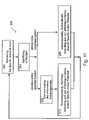
- FIGS. 1A-1Jschematically illustrate an intracorporeal apparatus for activating or inhibiting action-potential propagations, in a preselected nerve branch, in accordance with a preferred embodiment of the present invention
- FIGS. 2A and 2Bschematically illustrate an intracorporeal apparatus for activating or inhibiting action-potential propagations, in a preselected nerve branch, in accordance with another preferred embodiment of the present invention
- FIGS. 3A-3Cschematically illustrate an intracorporeal apparatus for activating or inhibiting action-potential propagations, in a preselected nerve branch, in accordance with still another preferred embodiment of the present invention
- FIGS. 4A and 4Bschematically illustrate an intracorporeal apparatus, in accordance with another preferred embodiment of the present invention.
- FIG. 5schematically illustrates an intracorporeal apparatus, for activating, inhibiting, selectively activating, or selectively inhibiting action-potential propagations, in a preselected nerve branch, in accordance with yet another preferred embodiment of the present invention
- FIG. 6schematically illustrates an intracorporeal apparatus, for activating, inhibiting, selectively activating, or selectively inhibiting action-potential propagations, in a preselected nerve branch, in accordance with still another preferred embodiment of the present invention
- FIGS. 7A-7Fschematically illustrate an intracorporeal apparatus for monitoring, activating, inhibiting, selectively activating, or selectively inhibiting action-potential propagations, in a preselected nerve branch, in accordance with yet another preferred embodiment of the present invention
- FIG. 8schematically illustrates modes of operation, in accordance with preferred embodiments of the present invention.
- FIGS. 9A-9Gschematically illustrate extracorporeal systems, in accordance with the present invention.
- FIG. 10schematically illustrates a closed-loop operational Flowchart, for activating, inhibiting, selectively activating, or selectively inhibiting action-potential propagations, in a preselected nerve branch, in accordance with a preferred embodiment of the present invention
- FIG. 11schematically illustrates a closed-loop operational Flowchart, for activating, inhibiting, selectively activating, or selectively inhibiting action-potential propagations, in a preselected nerve branch, in accordance with another preferred embodiment of the present invention.
- FIGS. 12A and 12Bschematically illustrate nerve junctions, at which nerve-branch-specific monitoring, activating, inhibiting, and (or) selectively activating may be applied, in accordance with the present invention.
- the present inventionis of a dual electrode arrangement, wherein two, preferably unidirectional, electrode configurations flank a nerve junction from which a preselected nerve branch issues, proximally and distally to the junction, with respect to the brain.
- the arrangementis conducive to the following: generating efferent action-potential propagations, substantially restricted to the preselected nerve branch, inhibiting afferent action-potential propagations, from the preselected nerve branch, selectively generating action-potential propagations, in a subset of nerve fibers of a predetermined diameter range, substantially restricted to the preselected nerve branch, and selectively inhibiting action-potential propagations, in a subset of nerve fibers of a predetermined diameter range, substantially restricted to the preselected nerve branch.
- the dual electrode arrangementis further conducive to monitoring naturally-occurring, efferent action-potential propagations, heading towards the preselected nerve branch, and monitoring naturally-occurring, afferent action-potential propagations, from the preselected nerve branch.
- the unidirectional electrode configurationsmay be monopolar, bipolar, tripolar, or multipolar. Communication with extracorporeal stations, and closed loop operations are provided.
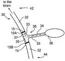
- FIGS. 1A-1Jschematically illustrate an intracorporeal apparatus 10 for activating or inhibiting action-potential propagations, in a preselected nerve branch, in accordance with a preferred embodiment of the present invention.
- Apparatus 10includes a cuff 11 ( FIGS. 1A-1D ), which houses electrode configurations 15 , a control unit 13 ( FIG. 1E ), and preferably also, a sensor unit 19 ( FIGS. 1A and 1H ), which is preferably intracorporeal.
- cuff 11includes two unidirectional-electrode configurations 15 , a proximal configuration 15 A and a distal configuration 15 B. Each is adapted for generating an action-potential propagation substantially in one direction, the unidirectional electrode configurations being arranged as mirror images to each other, so that the generated action-potential propagations are towards each other.
- Unidirectional-electrode configurations 15are positioned at a junction 35 of a nerve structure 30 , so as to flank a preselected nerve branch 34 , issuing from a trunk 32 and leading to an organ 36 .
- Junction 35defines a proximal side 42 and a distal side 44 , with respect to the brain, and cuff 11 is positioned with two unidirectional-electrode configurations 15 being proximally and distally to junction 35 .
- unidirectional-electrode configurations 15are bipolar, each formed as two conductive strips of an anode 14 and a cathode 16 , for example, of stainless steel, titanium, tantalum, gold, platinum, iridium, or another biocompatible, conductive substance.
- a cable 21provides communication with control unit 13 .
- cuff 11is constructed to form an insulating sleeve 12 , for example, of silicon, natural rubber, plastic, or the like, which houses electrode configurations 15 .
- electrodes 14 and 16are not flush with a proximal surface 25 with respect to the tissue. Rather, spacers 9 are provided to prevent the metal surface of electrodes 14 and 16 from making direct contact with the nerve tissue.
- spacers 9are formed of the same material as insulating sleeve 12 , or of a similar material, as taught in US Patent Application 20030050677, to Gross, et al., entitled, “Electrode assembly for nerve control,” whose disclosure is incorporated herein by reference. Additionally, spacers 9 provide for insulating electrodes 14 and 16 from each other.
- sleeve 12is preferably designed to close over nerve trunk 32 , preferably, with a locking mechanism 18 , preferably adjusting to the diameter of nerve trunk 32 .
- unidirectional-electrode configurations 15may be designed to form rings around nerve trunk 32 .
- cuff 11is designed for implantation around a nerve trunk, for example, the Vagus nerve trunk or the Pudental nerve trunk, at a nerve-branch junction, for example, in the neck region, for the Vagus nerve.
- a nerve trunkfor example, the Vagus nerve trunk or the Pudental nerve trunk
- a nerve-branch junctionfor example, in the neck region, for the Vagus nerve. Examples of nerve-trunk junctions, in accordance with the present invention, are illustrated hereinbelow, in conjunction with FIGS. 12A and 12B .
- control unit 13 of apparatus 10includes a power source 20 , for supplying power to apparatus 10 , a receiver 22 , or a transceiver 22 for receiving instructions from an extracorporeal station, described hereinbelow, in conjunction with FIGS. 9A-9G , and a controller 24 , which may be a dedicated circuit, a processor, an Application Specific Integrated Circuit (ASIC), or a microcomputer, as known. Controller 24 activates a pulse generator 26 , which drives electrode configurations 15 , via cable 21 .
- ASICApplication Specific Integrated Circuit
- control unit 13is designed for implantation percutaneously, preferably in the chest area. Tunneling under the skin may be used to implant cable 21 , connecting control unit 13 in the chest area and cuff 11 in the neck region.
- apparatus 10The operation of apparatus 10 is best understood with reference to FIGS. 1F and 1G .
- FIG. 1Fillustrates a situation of nerve-branch-specific activation.
- two electrode configurations 15 A and 15 Bare activated simultaneously, generating action potentials 37 and 39 , which propagate towards each other, so as to generate refractory periods for each other, when they meet. In this manner, substantial collision blocking of action potentials 37 and 39 occurs.
- an action potential 33generated by proximal electrode configuration 15 A, in these nerve fibers, has no corresponding action potential generated by distal electrode configuration 15 B.
- Action potential 33will thus travel to organ 36 , uninterrupted. In this manner, substantial nerve-branch specific activation takes place, allowing artificially induced action potentials to propagate substantially only through preselected nerve branch 34 .
- the action potentialsare thus substantially confined to the nerve region enclosed by electrode configurations 15 .
- the stimulation currentis preferably no greater than 20 mA, but it will be appreciated that this value may be exceeded.
- FIG. 1Gillustrates a situation of nerve-branch-specific inhibition, of an afferent action potential 31 , which originates from organ 36 .
- two electrode configurations 15are activated simultaneously, generating action potentials 37 and 39 , which propagate towards each other, so as to generate refractory periods for each other, when they meet.
- action potential 33generated by proximal electrode configuration 15 A, in the nerve fibers leading to organ 36 will generate a refractory period for an action potential 31 from organ 36 , when they meet, thus substantially inhibiting action potential 31 from organ 36 .
- substantial nerve-branch inhibitiontakes place, specific to preselected nerve branch 34 .
- the action potentialsare again substantially confined to the nerve region enclosed by electrode configurations 15 .
- nerve branch 34may be very fine, and implanting an electrode directly on it may be technically difficult. However, implanting cuff 11 on nerve trunk 32 is feasible. In accordance with the present invention, action potential may be induced to propagate only along nerve branch 34 , even as cuff 11 is mounted on larger trunk 32 .
- apparatus 10may further include intracorporeal sensor unit 19 , which includes a physiological sensor 17 , for sensing a physiological condition associated with organ 36 .
- a cable 23connects sensor 17 to controller 24 of control unit 13 .
- an amplifying componentmay also be used, either incorporated to sensor unit 19 , or to control unit 13 , or to both.
- Organ 36may be a heart, and sensor 17 may be, for example, a heart-rate sensor, for detecting periods of sleep, or an electrocardiograph (EKG) sensor for detecting an onset of seizure.
- organ 36may be a stomach, and sensor 17 may be, for example, an acid sensor, for sensing stomach acid, or a tensile sensor, for sensing muscle contractions.
- a pressure sensormay be used, for sensing the blood flow rate. It will be appreciated that other physiological sensors, may be used, and may be adapted for other organs.
- Sensor unit 19is designed for implantation within organ 36 ( FIG. 1A ), while communicating with control unit 13 via a cable 23 . Again, tunneling may be used to pass cable 17 , connecting control unit 13 in the chest area and sensor unit 19 , in organ 36 . It will be appreciated that wireless communication between sensor unit 19 and control unit 13 is also possible, for example, by ultrasound, IR, or RF.
- FIG. 1Iillustrates apparatus 10 , which is implanted in a person 50 , wherein cuff 11 is implanted in the neck region, control unit 13 is implanted in the chest area, and sensor unit 19 is implanted in a heart 52 , heart 52 being organ 36 in this case.
- FIG. 1Jillustrates apparatus 10 , which is implanted in person 50 , wherein sensor unit 19 is implanted in a stomach 54 , stomach 54 being organ 36 in that case.
- bipolar unidirectional electrode configurations 15may be designed according to the teaching of U.S. Pat. No. 4,628,942, to Sweeney, et al., entitled, “Asymmetric shielded two electrode cuff,” whose disclosure is incorporated herein by reference.
- Sweeney, et al.teach an annular electrode cuff positioned around a nerve trunk, for imposing electrical signals on to the nerve trunk for the purpose of generating unidirectionally propagated action potentials.
- the electrode cuffincludes an annular cathode having a circular passage therethrough of a first diameter.
- An annular anodehas a larger circular passage therethrough of a second diameter, which second diameter is about 1.2 to 3.0 times the first diameter.
- a non-conductive sheathextends around the anode, cathode, and nerve trunk.
- the anode and cathodeare placed asymmetrically to one side of the non-conductive sheath.
- a first length along the electrode sheath between a first end and the cathodeis at least twice a second length between the anode and cathode.
- a third length between the anode and a second end of the conductive sheathis smaller than the first or second lengths.
- the mirror image arrangementis preferably, cathode to cathode, as taught in conjunction with FIGS. 1A-1C .
- Two unidirectional electrode configurations 15may be arranged on a single cuff, for example, as shown in conjunction with FIGS. 1A-1C , or on two separate cuffs, as shown in conjunction with FIGS. 2A-2B .
- FIGS. 2A and 2Bschematically illustrate an intracorporeal apparatus 40 for activating or inhibiting action-potential propagations, in preselected nerve branch 34 , in accordance with another preferred embodiment of the present invention.
- Apparatus 40includes two cuffs 41 , each comprising a single unidirectional electrode configuration 15 , wherein cuffs 41 are arranged as mirror images to each other and are connected with cable 21 .
- apparatus 40 of the present embodimentis similar to apparatus 10 of FIGS. 1A-1J .
- FIGS. 3A-3Cschematically illustrate an intracorporeal apparatus 70 for activating or inhibiting action-potential propagations, in preselected nerve branch 34 , in accordance with still another preferred embodiment of the present invention.
- Apparatus 70includes an asymmetrical cuff 71 , comprising two monopolar, unidirectional electrode configurations 15 , arranged as mirror images to each other, so that the generated action-potential propagations are towards each other.
- each monopolar unidirectional electrode configuration 15is designed in accordance with the teachings of U.S. Pat. No. 4,649,936, to Ungar, et al., entitled, “Asymmetric single electrode cuff for generation of unidirectionally propagating action potentials for blocking,” whose disclosure is incorporated herein by reference.
- Ungar, et al.teach a unidirectional electrode configuration of a single electrode, positioned in an asymmetric electrode cuff, formed of a dielectric sleeve.
- a cathode 72is positioned at a first distance L 1 from an escape end 77 and at a second distance L 2 from an arrest end 75 .
- First distance L 1is at least 1.7, and preferably about 7 times second distance L 1 .
- An anode 74is physically disconnected from cuff 71 and is implanted in the tissue, wherein a cable 76 provides communication with a control unit 73 .
- a cable 76provides communication with a control unit 73 .
- anode 74is far from cuff 71 , for example, in the chest area.
- anode 74may be integrated with control unit 73 , in which case cable 76 need not be used.
- Control unit 73preferably includes power source 20 , transceiver 22 , controller 24 , and pulse generator 26 . Controller 24 activates pulse generator 26 , for driving electrode configurations 15 , via a cable 79 , which leads to cables 21 and 76 .
- the asymmetry formed by the positioning of cathode 72 in cuff 71causes a primary or forward stimulus signal current to be correspondingly greater than a secondary or reverse current.
- stimuli generated by electrode configuration 15 of the present embodimentwill travel substantially unidirectionally, from arrest end 75 towards escape end 77 .
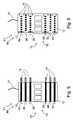
- FIGS. 4A and 4Bschematically illustrate an intracorporeal apparatus 80 , in accordance with another preferred embodiment of the present invention.
- Apparatus 80includes a cuff 81 , comprising two tripolar unidirectional electrode configurations 15 , arranged as mirror images to each other.
- Each unidirectional electrode configuration 15may be designed, for example, as a cathode 86 , an anode 84 , and a secondary anode 88 , and the mirror image arrangement may be, for example, cathode 86 to cathode 86 .
- each unidirectional electrode configuration 15 of apparatus 80may be designed according to the teaching of commonly owned US Patent Application 20030050677, to Gross, et al., entitled, “Electrode assembly for nerve control,” whose disclosure is incorporated herein by reference.
- Gross, et al.teach an apparatus for applying current to a nerve, the apparatus being designed to reduce the virtual cathode effect.
- a cathodeis adapted to be placed in a vicinity of a cathodic longitudinal site of the nerve and to apply a cathodic current to the nerve.
- a primary inhibiting anodeis adapted to be placed in a vicinity of a primary anodal longitudinal site of the nerve and to apply a primary anodal current to the nerve.
- a secondary inhibiting anodeis adapted to be placed in a vicinity of a secondary anodal longitudinal site of the nerve and to apply a secondary anodal current to the nerve, the secondary anodal longitudinal site being closer to the primary anodal longitudinal site than to the cathodic longitudinal site.
- the secondary anodal currentis of lower magnitude than the primary anodal current.
- the virtual cathode effectcan stimulate, rather than block, the generation of action potentials in fibers in a region adjacent to the application of anodal current of a sufficiently high magnitude.
- the apparatusmay include a housing to which the cathode and a plurality of anodes are coupled, wherein one of the anodes is positioned within the housing so as to reduce a virtual cathode effect induced by another one of the anodes.
- FIG. 5schematically illustrates an alternative design for apparatus 80 , for activating, inhibiting, selectively activating, or selectively inhibiting action-potential propagations, in preselected nerve branch 34 , in accordance with yet another preferred embodiment of the present invention.
- cathode 86is flanked by two anodes, 84 and 88 , and the mirror image arrangement is secondary anode 88 to secondary anode 88 .
- an axon's sensitivity to stimulationincreases with its diameter. This sensitivity is both for activation by cathodic stimulation and inhibition by anodic stimulation.
- nerve stimulationis performed with the cathode. As the current is increased, fibers of lower diameters are “recruited,” or stimulated. At a low current, only A fibers are activated, while at a higher current, both A and B fibers are activated.
- the currentis divided between the primary and secondary anodes, such that while the cathode operates at a current that activate both A and B fibers, the primary anode inhibits A fibers, by hyper-polarization tuned specifically for these larger-diameter fibers.
- an overall activation of B fibersis achieved, with the action potential propagation in the B fibers being towards the secondary anode. In this manner it is possible to predefine a range of nerve-fiber diameters and activate them specifically.
- selective nerve stimulationcan be used in conjunction with nerve-branch-specific stimulation to achieve selective stimulation of a specific range of fiber diameters, substantially restricted to a preselected nerve branch.
- Heart rate controlThe heart is innervated only by Vagal B fibers, while A fibers innervate other muscles. Activating A fibers will cause severe side effects such as coughing and voice changes, so it is desired to activate only the B fibers;
- Muscle controlB fibers control fine movements, while A fibers produce big contractions.
- the unidirectional tripolar electrode designis in accordance with the teaching of D. M. Fitzpatrick et al., “A Nerve Cuff Design for the Selective Activation and Blocking of Myelinated Nerve Fibers”, Ann. Conf. of the IEEE Eng. in Medicine and Biology Soc., Vol. 13, No. 2, pp. 906, 1991.
- the tripolar electrode used for muscle controlincludes a central cathode flanked on its opposite sides by two anodes.
- the central cathodegenerates action potentials in the motor nerve fiber by cathodic stimulation; one anode produces a complete anodal block in one direction so that the action potential produced by the cathode is unidirectional; and the other anode produces a selective anodal block to permit passage of the action potential in the opposite direction through selected motor nerve fibers to produce the desired muscle stimulation or suppression.
- selective stimulationmay also be achieved in accordance with the teaching of J. F. X. Jones, Y. Wang, and D. Jordan (1995): Heart Rate Response to Selective Stimulation of Cardiac Vagal C-Fibers in Anesthetized Cats, Rats, and Rabbits,” J. Physiol., 489, 203-214, incorporated herein by reference, which describes the use of two bipolar electrodes to stimulate only a certain group of fibers (for example, only C-fibers), based on their diameters.
- bipolar electrode configurationsmay be used, two bipolar electrode configurations on proximal side 42 , with the unidirectional direction of both being distally, and two bipolar electrode configurations on distal side 44 of nerve junction 35 , with the unidirectional direction of both being proximally.
- the described preferred embodimentsthere are a plurality of electrode devices spaced along the length of the nerve bundle which are sequentially actuated with delays corresponding to the velocity of propagation of the body-generated action potentials through the large-diameter fibers to produce a “green wave” effect which minimizes undesired anodal blocking of the large-diameter fibers while maximizing the collision blocking of the small-diameter fibers.
- an arrangement of two pluralities of electrode devicesmay be used, a first plurality on proximal side 42 , with its unidirectional direction being distally, and a second plurality on distal side 44 of nerve junction 35 , with its unidirectional direction being proximally.
- each unidirectional electrode configuration 15may include a plurality of electrodes, as taught by commonly owned US Patent Application 20030050677, to Gross, et al., entitled, “Electrode assembly for nerve control,” describe hereinabove.
- each unidirectional electrode configuration 15may be designed according to the teaching of commonly owned US Patent application 20030045914A1, to Cohen, et al., entitled, “Treatment of disorders by unidirectional nerve stimulation,” whose disclosure is incorporated herein by reference.
- Cohen, et al.teach an apparatus for treating a condition of a subject.
- An electrode deviceis adapted to be coupled to longitudinal nervous tissue of the subject, and a control unit is adapted to drive the electrode device to apply to the nervous tissue a current, which is capable of inducing action potentials that propagate in the nervous tissue in a first direction, so as to treat the condition.
- the control unitis further adapted to suppress action potentials from propagating in the nervous tissue in a second direction opposite to the first direction.
- the electrodesmay be configured to induce efferent nerve impulses (i.e., action potentials propagating in the direction of organ 36 ), while suppressing afferent nerve impulses traveling towards the brain.
- the method of US Patent application 20030045914A1, to Cohen, et al.includes applying a plurality of electrode devices to the nerve bundle, spaced at intervals along the bundle.
- Each electrode deviceis capable of inducing, when actuated, unidirectional “electrode-generated” action potentials, which produce collision blocks with respect to the naturally-generated action potentials propagated through the second group of nerve fibers.
- each electrode deviceis actuated in sequence, with inter-device delays timed to generally match the first conduction velocity and to thereby produce a wave of anodal blocks, which: (a) minimize undesired blocking of the naturally-generated action potentials propagated through the first group of nerve fibers, while (b) maximizing the generation rate of the unidirectional electrode-generated action potentials which produce collision blocks of the naturally-generated action potentials propagated through the second group of nerve fibers.
- Such a methodmay be used for producing collision blocks in sensory nerve fibers in order to suppress pain, and also in motor nerve fibers to suppress selected muscular or glandular activities.
- selective stimulationcan be achieved with a monopolar electrode, as taught in conjunction with FIGS. 3A-3C , for example, according to Ungar I. J. et al., “Generation of unidirectionally propagating action potentials using a monopolar electrode cuff,” Annals of Biomedical Engineering, 14:437-450 (1986).
- asymmetrical cuff 71the relative sizes of the virtual anodes near edges 75 and 77 of cuff 71 can be controlled. Adjusting the relative distances of cathode 72 from edges 75 and 77 enables one to get a configuration similar to that of a tripolar electrode and thus achieve selectiveness.
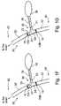
- FIG. 6schematically illustrates an alternative design for apparatus 80 , for activating, inhibiting, selectively activating, or selectively inhibiting action-potential propagations, in preselected nerve branch 34 , in accordance with still another preferred embodiment of the present invention.
- the electrodesare formed as pads.
- FIGS. 7A-7Fschematically illustrate an intracorporeal apparatus for monitoring, activating, inhibiting, selectively activating, or selectively inhibiting action-potential propagations, in a preselected nerve branch, in accordance with yet another preferred embodiment of the present invention.
- electrode configurations 15may be operative to sense naturally occurring efferent and afferent action potentials propagating through nerve trunk 32 .
- afferent action-potential propagations 43from organ 36 , relating for example, to diffused pain, will be sensed by proximal electrode configuration 15 A, but not by distal electrode configuration 15 B.
- afferent action-potential propagations 45from an organ more distal than organ 36 , will be sensed by both electrode configurations 15 A and 15 B.
- controller 24may determine when afferent action-potential propagations originate from organ 36 .
- efferent action-potential propagations 47heading towards organ 36
- proximal electrode configuration 15 Awith respect to the brain, but not by distal electrode configuration 15 B.
- efferent action-potential propagations 49heading towards an organ more distal than organ 36
- controller 24may determine when efferent action-potential propagations are heading towards organ 36 .
- electrode configurations 15 A and 15 Bneed not be unidirectional. Any two electrode configurations, implanted on nerve trunk 32 , so as to flank junction 35 , may be operative for discriminating between action potentials associated with organ 36 and those associated with more distal organs.
- apparatus 85is constructed in accordance with any one of the embodiments provided hereinabove. However, in general, some amplification is required for the sensed signals to be properly evaluated.
- control unit 83preferably includes at least one amplifying component 28 , in communication with controller 24 .
- cable 21which provides communication between control unit 83 and cuff 81 splits into a cable 21 A, which leads from pulse generator 26 to electrode configurations 15 , on cuff 81 , and a cable 21 B, which leads from electrode configurations 15 to amplifying component 28 .
- incoming signals from electrode configurations 15are amplified before reaching controller 24 , for evaluation.
- a tripolar, unidirectional electrode configurationfor example, as taught by D. M. Fitzpatrick et al., “A Nerve Cuff Design for the Selective Activation and Blocking of Myelinated Nerve Fibers”, Ann. Conf. of the IEEE Eng. in Medicine and Biology Soc., Vol. 13, No. 2, pp. 906, 1991, may be used.
- another electrode configurationpreferably adapted for selective nerve-branch-specific activation and (or) inhibition, may be used.
- sensor unit 19when monitoring of the nerve trunk takes place, sensor unit 19 need not be used, since activities of organ 36 are sensed through the nerve trunk. It will be appreciated that sensor unit 19 may still be used, when desired.
- monitoring nerve trunk 32 by electrode configurations 15 A and 15 Bmay be used for evaluating the condition of the nerve trunk, as a function of time, for example, for possible effects of electrostimulation.
- FIG. 7Fschematically illustrates an intracorporeal apparatus 59 for activating an action-potential propagation, in preselected nerve branch 34 , in accordance with another embodiment of the present invention.
- proximal electrode configuration 15 Ais a cathode
- distal electrode configuration 15 Bis an anode.
- Activation of action potential propagations 51 and 53takes place by cathode 15 A, while inhibition of action potential propagation 51 by local hyperpolarization is performed by anode 15 B, to prevent action potential propagation 51 from propagating beyond anode 15 B.
- action potential propagation 53which is specific to the nerve fibers leading to organ 36 , continues in nerve branch 34 , towards organ 36 .
- i. proximal electrode configuration 15 Aalso activates action potential propagations 55 and 57 , to the brain, and these are not blocked;
- the anodal blockalso blocks other naturally occurring action potentials passing through anode 15 B.
- the operational modes of the intracorporeal apparatus of FIGS. 1A-7Fmay be any one, or a combination of the following:
- FIG. 8schematically illustrates a Flowchart 150 , of preprogrammed operational modes of intracorporeal controller 24 ( FIGS. 1E , 3 C, 7 C), in accordance with preferred embodiments of the present invention.
- intracorporeal controller 24may be programmed for continuous operation, at predetermined intervals.
- controller 24may be programmed for operation, responsive to a demand from an extracorporeal station, communicated to transceiver 22 ( FIGS. 1E , 3 C, 7 C), for example, as described hereinbelow, in conjunction with FIGS. 9A-9G .
- the extracorporeal demandmay come from person 50 ( FIGS. 1I , 1 J, and 7 D), from a caretaker (not shown), or from a monitoring call center described hereinbelow in conjunction with FIG. 9G .
- controller 24may be programmed for operation, responsive to input from sensor 17 , implanted in organ 36 ( FIGS. 1H-1J ).
- controller 24may be programmed for operation, responsive to the monitoring of electrode configurations 15 A and 15 B ( FIGS. 7A-7D ).
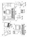
- FIGS. 9A-9Gschematically illustrate various extracorporeal systems 100 , adapted for communication with intracorporeal controller 24 ( FIGS. 1E , 3 C, 7 C), via receiver 22 or transceiver 22 , and possibly also with each other and (or) with a monitoring call center 130 , in accordance with the present invention.
- extracorporeal system 100may be a remote-control unit 90 , which may include a display panel 92 , control buttons 94 , a connector 96 for connection to a computer system, preferably being a USB connector, a transmitter 98 , which may further operate as a transceiver 98 , preferably, an antenna 91 , a power source 93 , and preferably also a plug for recharging power source 95 . It will be appreciated that a separate receiver may be used.
- Transceiver 98may operate by RF, IR and may employ BlueTooth protocol.
- extracorporeal system 100may be a mobile phone ( FIG. 9B ), a telephone ( FIG. 9C ), a palmtop or PDA ( FIG. 9D ), a laptop ( FIG. 9E ), a computer ( FIG. 9F ), or another remote system, as known.
- extracorporeal systems 100include display panels 92 and control buttons 94 .
- Communication between extracorporeal systems 100may be performed via connectors and cables, for example, via USB connectors, or by telephone, or in a wireless manner, by RF or IR waves, for example, using BlueTooth protocol.
- extracorporeal system 100may further communicate with monitoring call center 130 ( FIG. 9G ), for example, by phone, or by mobile phone.
- Monitoring call center 130may be a clinic, a heath center, or another monitoring center, as applicable, for overseeing, monitoring, and evaluating the operation of apparatus 10 , 40 , 70 , 80 and (or) 85 .
- monitoring call center 130includes an attendant 136 , such as a medical practitioner, a nurse, a social worker, and (or) another attendant, as applicable, a computer system 132 , and a telephone or cell phone 134 .
- Monitoring call center 130may also be a center-on-the-go, for example, of medical practitioner 136 , his laptop 132 , and his cell phone 134 .
- Communicationmay include:
- processing of signals from sensor unit 19 ( FIG. 1H ) or apparatus 85 ( FIG. 7A-7D )may be performed by intracorporeal controller 24 ( FIGS. 1E , 3 C, 7 C), by extracorporeal system 100 , or by monitoring call center 130 ( FIG. 96 ).
- any one of extracorporeal systems 100may be designed as a telephone or a cell phone with specific codes for quick and easy communication both with monitoring call center 130 and with intracorporeal controller 24 ( FIGS. 1E , 3 C, 7 C).
- dialing * 10may reach medical attendant 136 at monitoring call center 130
- dialing * 11may reach computer system 132 at monitoring call center 130
- dialing * 12may communicate with intracorporeal controller 24 ( FIGS. 1E , 3 C, 7 C) and initiate activation.
- FIG. 10schematically illustrates a closed-loop operational Flowchart 110 , for activating, inhibiting, selectively activating, or selectively inhibiting action-potential propagations, in preselected nerve branch 34 , in accordance with a preferred embodiment of the present invention.
- sensor unit 19monitors organ 36 .
- intracorporeal controller 24( FIGS. 1E , 3 C, 7 C) will activate, inhibit, or selectively activate action-potential propagations, substantially only in preselected nerve branch 34 , responsive to the situation of Box 114 .
- extracorporeal system 100or monitoring call center 130 , via extracorporeal system 100 , will activate, inhibit, or selectively activate action-potential propagations, substantially only in preselected nerve branch 34 , responsive to the situation of Box 114 .
- FIG. 11schematically illustrates a closed-loop operational Flowchart 200 , for activating, inhibiting, selectively activating, or selectively inhibiting action-potential propagations, in preselected nerve branch 34 , in accordance with another preferred embodiment of the present invention.
- apparatus 85monitors preselected nerve branch 34 , via action potentials passing through electrode configurations 15 A and 15 B on nerve trunk 32 .
- intracorporeal controller 24( FIGS. 1E , 3 C, 7 C) will activate, inhibit, or selectively activate action-potential propagations, substantially only in preselected nerve branch 34 , responsive to the situation of Box 204 .
- extracorporeal system 100or monitoring call center 130 , via extracorporeal system 100 , will activate, inhibit, or selectively activate action-potential propagations, substantially only in preselected nerve branch 34 , responsive to the situation of Box 204 .
- FIGS. 12A and 12Bschematically illustrate nerve junctions, at which nerve-branch-specific monitoring, activating, inhibiting, and (or) selectively activating may be applied, in accordance with the present invention.
- the junctionsinclude the Vagus nerve and its related branches and the Pudental nerve and its related branches. Arrows in both directions indicate that a particular branch may be either activated or inhibited. Arrows in the direction of an organ only, indicate that only activation is important.
- Table 1provides examples of the types of nerve activation and inhibition that may be applied, in accordance with the present invention. It will be appreciated that monitoring, activating, inhibiting, and (or) selectively activating may be applied to other nerve structures and junctions as well.
Landscapes
- Health & Medical Sciences (AREA)
- Neurology (AREA)
- Neurosurgery (AREA)
- Orthopedic Medicine & Surgery (AREA)
- Cardiology (AREA)
- Heart & Thoracic Surgery (AREA)
- Engineering & Computer Science (AREA)
- Biomedical Technology (AREA)
- Nuclear Medicine, Radiotherapy & Molecular Imaging (AREA)
- Radiology & Medical Imaging (AREA)
- Life Sciences & Earth Sciences (AREA)
- Animal Behavior & Ethology (AREA)
- General Health & Medical Sciences (AREA)
- Public Health (AREA)
- Veterinary Medicine (AREA)
- Electrotherapy Devices (AREA)
Abstract
Description
- i. The absolute refractory period is the time during which no stimulus can initiate a new action potential.
- ii. The relative refractory period is the time during which a hyper-threshold stimulus can initiate an action potential.
∇(σ∇U)=4πj
- a proximal electrode configuration, implanted on a nerve trunk, proximally to a junction of the nerve trunk with a preselected nerve branch; and
- a distal electrode configuration, implanted on the nerve trunk, distally to the junction.
- a proximal electrode configuration, implanted on a nerve trunk, proximally to a junction of the nerve trunk with a preselected nerve branch; and
- a distal electrode configuration, implanted on the nerve trunk, distally to the junction; and
- i. generating efferent action-potential propagations, substantially restricted to preselected
nerve branch 34; - ii. inhibiting afferent action-potential propagations, from
nerve branch 34; - iii. selectively generating action-potential propagations, in a subset of nerve fibers of a predetermined diameter range, substantially restricted to preselected
nerve branch 34; - iv. selectively inhibiting action-potential propagations, in a subset of nerve fibers of a predetermined diameter range, substantially restricted to preselected
nerve branch 34; - v. monitoring efferent action-potential propagations, leading to
preselected nerve branch 34; and - vi. monitoring afferent action-potential propagations, from
nerve branch 34.
- i. generating efferent action-potential propagations, substantially restricted to preselected
- 1. information from sensor unit19 (
FIG. 1H ) or apparatus85 (FIG. 7A-7D ) toextracorporeal system 100, and from it, possibly also to monitoringcall center 130; and - 2. instructions from
extracorporeal system 100, or possibly also from monitoringcall center 130, viaextracorporeal system 100, to intracorporeal controller24 (FIGS. 1E ,3C,7C), for example, to monitor, activate, inhibit, and (or) selectively activate action-potential propagations, of a specified current, frequency, and waveform, to discontinue monitoring, activating, inhibiting, and (or) selectively activating, or to change certain operational parameters.
| TABLE 1 | |||||
| Nerve | Nerve | Acti- | Sensory | ||
| Trunk | Branch | vate | Block | Application | Input |
| Vagus | Superior | √ | decrease heart | heart-rate | |
| cardiac | rate, for heart | sensor, to | |||
| failure patients | indicate HR | ||||
| Vagus | Inferior | √ | decrease heart | heart-rate | |
| cardiac | rate, for heart | sensor, to | |||
| failure patients | indicate HR | ||||
| Vagus | Thoracic | √ | decrease heart | heart-rate | |
| cardiac | rate, for heart | sensor, to | |||
| failure patients | indicate HR | ||||
| Vagus | Gastric | √ | Increase gastric | Patient request | |
| motility locally, | Gastric Acidity | ||||
| Treat gastric | Esophageal | ||||
| atonia, | contractions | ||||
| Stop nausea, | |||||
| vomiting | |||||
| Vagus | Gastric | √ | Reduce appetite | Patient request | |
| Treat dyspepsia | |||||
| Vagus | Intestine | √ | Increase intestinal | Patient request | |
| motility locally, | Time of day | ||||
| Treat intestinal | |||||
| atonia | |||||
| Treat constipation | |||||
| Treat Irritable | |||||
| bowel syndrome | |||||
| Vagus | Intestine | √ | stop nausea, | Patient request | |
| vomiting Treat | Time of day | ||||
| Irritable bowel | |||||
| syndrome | |||||
| Pudental | inferior | √ | treat fecal | Rectal pressure | |
| rectal | incontinence | Abdominal | |||
| Pressure | |||||
| Pudental | perineal | √ | treat fecal | Rectal pressure | |
| nerve | incontinence | Abdominal | |||
| Pressure | |||||
| Pudental | Dorsal | √ | cause erection to | Patient request | |
| nerve | treat impotence | ||||
| of penis | |||||
Claims (50)
Priority Applications (1)
| Application Number | Priority Date | Filing Date | Title |
|---|---|---|---|
| US10/745,514US7295881B2 (en) | 2003-12-29 | 2003-12-29 | Nerve-branch-specific action-potential activation, inhibition, and monitoring |
Applications Claiming Priority (1)
| Application Number | Priority Date | Filing Date | Title |
|---|---|---|---|
| US10/745,514US7295881B2 (en) | 2003-12-29 | 2003-12-29 | Nerve-branch-specific action-potential activation, inhibition, and monitoring |
Publications (2)
| Publication Number | Publication Date |
|---|---|
| US20050149154A1 US20050149154A1 (en) | 2005-07-07 |
| US7295881B2true US7295881B2 (en) | 2007-11-13 |
Family
ID=34710608
Family Applications (1)
| Application Number | Title | Priority Date | Filing Date |
|---|---|---|---|
| US10/745,514Expired - LifetimeUS7295881B2 (en) | 2003-12-29 | 2003-12-29 | Nerve-branch-specific action-potential activation, inhibition, and monitoring |
Country Status (1)
| Country | Link |
|---|---|
| US (1) | US7295881B2 (en) |
Cited By (92)
| Publication number | Priority date | Publication date | Assignee | Title |
|---|---|---|---|---|
| US20060271137A1 (en)* | 2005-05-25 | 2006-11-30 | The Cleveland Clinic Foundation | Apparatus and system to stimulate a nerve |
| US20070112402A1 (en)* | 2005-10-19 | 2007-05-17 | Duke University | Electrode systems and related methods for providing therapeutic differential tissue stimulation |
| US20090012590A1 (en)* | 2007-07-03 | 2009-01-08 | Cyberonics, Inc. | Neural Conductor |
| US7869884B2 (en) | 2007-04-26 | 2011-01-11 | Cyberonics, Inc. | Non-surgical device and methods for trans-esophageal vagus nerve stimulation |
| US7904175B2 (en) | 2007-04-26 | 2011-03-08 | Cyberonics, Inc. | Trans-esophageal vagus nerve stimulation |
| US7925352B2 (en) | 2008-03-27 | 2011-04-12 | Synecor Llc | System and method for transvascularly stimulating contents of the carotid sheath |
| US7962214B2 (en) | 2007-04-26 | 2011-06-14 | Cyberonics, Inc. | Non-surgical device and methods for trans-esophageal vagus nerve stimulation |
| US8116883B2 (en) | 2003-06-04 | 2012-02-14 | Synecor Llc | Intravascular device for neuromodulation |
| US8239028B2 (en) | 2009-04-24 | 2012-08-07 | Cyberonics, Inc. | Use of cardiac parameters in methods and systems for treating a chronic medical condition |
| US8303516B2 (en) | 2007-09-06 | 2012-11-06 | Baxano, Inc. | Method, system and apparatus for neural localization |
| US8337404B2 (en) | 2010-10-01 | 2012-12-25 | Flint Hills Scientific, Llc | Detecting, quantifying, and/or classifying seizures using multimodal data |
| US8366712B2 (en) | 2005-10-15 | 2013-02-05 | Baxano, Inc. | Multiple pathways for spinal nerve root decompression from a single access point |
| US8382667B2 (en) | 2010-10-01 | 2013-02-26 | Flint Hills Scientific, Llc | Detecting, quantifying, and/or classifying seizures using multimodal data |
| US8394102B2 (en) | 2009-06-25 | 2013-03-12 | Baxano, Inc. | Surgical tools for treatment of spinal stenosis |
| US8398641B2 (en) | 2008-07-01 | 2013-03-19 | Baxano, Inc. | Tissue modification devices and methods |
| US8409206B2 (en) | 2008-07-01 | 2013-04-02 | Baxano, Inc. | Tissue modification devices and methods |
| US8417344B2 (en) | 2008-10-24 | 2013-04-09 | Cyberonics, Inc. | Dynamic cranial nerve stimulation based on brain state determination from cardiac data |
| US8452387B2 (en) | 2010-09-16 | 2013-05-28 | Flint Hills Scientific, Llc | Detecting or validating a detection of a state change from a template of heart rate derivative shape or heart beat wave complex |
| WO2013086168A1 (en) | 2011-12-07 | 2013-06-13 | Cyberonics, Inc. | Implantable device for facilitating control of electrical stimulation of cervical vagus nerves for treatment of chronic cardiac dysfunction |
| WO2013086163A1 (en) | 2011-12-07 | 2013-06-13 | Cyberonics, Inc. | Computer - implemented system for selecting therapy profiles of electrical stimulation of cervical vagus nerves for treatment of chronic cardiac dysfunction |
| WO2013086170A1 (en) | 2011-12-07 | 2013-06-13 | Cyberonics, Inc. | Implantable device for evaluating autonomic cardiovascular drive in a patient suffering from chronic cardiac dysfunction |
| WO2013086175A1 (en) | 2011-12-07 | 2013-06-13 | Cyberonics, Inc. | Implantable device for providing electrical stimulation of cervical vagus nerves for treatment of chronic cardiac dysfunction with bounded titration |
| WO2013109770A1 (en) | 2012-01-17 | 2013-07-25 | Cyberonics, Inc. | Vagus nerve neurostimulator with multiple patient-selectable modes for treating chronic cardiac dysfunction |
| US8551097B2 (en) | 2006-08-29 | 2013-10-08 | Baxano Surgical, Inc. | Tissue access guidewire system and method |
| US8562536B2 (en) | 2010-04-29 | 2013-10-22 | Flint Hills Scientific, Llc | Algorithm for detecting a seizure from cardiac data |
| US8565896B2 (en) | 2010-11-22 | 2013-10-22 | Bio Control Medical (B.C.M.) Ltd. | Electrode cuff with recesses |
| US8562524B2 (en) | 2011-03-04 | 2013-10-22 | Flint Hills Scientific, Llc | Detecting, assessing and managing a risk of death in epilepsy |
| US8562523B2 (en) | 2011-03-04 | 2013-10-22 | Flint Hills Scientific, Llc | Detecting, assessing and managing extreme epileptic events |
| US8571653B2 (en) | 2001-08-31 | 2013-10-29 | Bio Control Medical (B.C.M.) Ltd. | Nerve stimulation techniques |
| US8571651B2 (en) | 2006-09-07 | 2013-10-29 | Bio Control Medical (B.C.M.) Ltd. | Techniques for reducing pain associated with nerve stimulation |
| US8577458B1 (en) | 2011-12-07 | 2013-11-05 | Cyberonics, Inc. | Implantable device for providing electrical stimulation of cervical vagus nerves for treatment of chronic cardiac dysfunction with leadless heart rate monitoring |
| US8579902B2 (en) | 2004-10-15 | 2013-11-12 | Baxano Signal, Inc. | Devices and methods for tissue modification |
| US8585704B2 (en) | 2006-05-04 | 2013-11-19 | Baxano Surgical, Inc. | Flexible tissue removal devices and methods |
| US8613745B2 (en) | 2004-10-15 | 2013-12-24 | Baxano Surgical, Inc. | Methods, systems and devices for carpal tunnel release |
| WO2014014787A1 (en) | 2012-07-20 | 2014-01-23 | Cyberonics, Inc. | Implantable neurostimulator for managing bradycardia through vagus nerve|stimulation |
| US8641646B2 (en) | 2010-07-30 | 2014-02-04 | Cyberonics, Inc. | Seizure detection using coordinate data |
| US8649871B2 (en) | 2010-04-29 | 2014-02-11 | Cyberonics, Inc. | Validity test adaptive constraint modification for cardiac data used for detection of state changes |
| US8647346B2 (en) | 2004-10-15 | 2014-02-11 | Baxano Surgical, Inc. | Devices and methods for tissue modification |
| US8652138B2 (en) | 2004-10-15 | 2014-02-18 | Baxano Surgical, Inc. | Flexible tissue rasp |
| US8663228B2 (en) | 2007-12-07 | 2014-03-04 | Baxano Surgical, Inc. | Tissue modification devices |
| US8679009B2 (en) | 2010-06-15 | 2014-03-25 | Flint Hills Scientific, Llc | Systems approach to comorbidity assessment |
| US8684921B2 (en) | 2010-10-01 | 2014-04-01 | Flint Hills Scientific Llc | Detecting, assessing and managing epilepsy using a multi-variate, metric-based classification analysis |
| US8700150B2 (en) | 2012-01-17 | 2014-04-15 | Cyberonics, Inc. | Implantable neurostimulator for providing electrical stimulation of cervical vagus nerves for treatment of chronic cardiac dysfunction with bounded titration |
| US8725239B2 (en) | 2011-04-25 | 2014-05-13 | Cyberonics, Inc. | Identifying seizures using heart rate decrease |
| US8801626B2 (en) | 2004-10-15 | 2014-08-12 | Baxano Surgical, Inc. | Flexible neural localization devices and methods |
| US8827912B2 (en) | 2009-04-24 | 2014-09-09 | Cyberonics, Inc. | Methods and systems for detecting epileptic events using NNXX, optionally with nonlinear analysis parameters |
| US8831732B2 (en) | 2010-04-29 | 2014-09-09 | Cyberonics, Inc. | Method, apparatus and system for validating and quantifying cardiac beat data quality |
| US8845639B2 (en) | 2008-07-14 | 2014-09-30 | Baxano Surgical, Inc. | Tissue modification devices |
| WO2014159701A2 (en) | 2013-03-14 | 2014-10-02 | Cyberonics, Inc. | Implantable neurostimulator-implemented method for managing tachyarrhythmic risk during sleep through vagus nerve stimulation |
| US8923964B2 (en) | 2012-11-09 | 2014-12-30 | Cyberonics, Inc. | Implantable neurostimulator-implemented method for enhancing heart failure patient awakening through vagus nerve stimulation |
| EP2818199A1 (en) | 2013-06-30 | 2014-12-31 | Cyberonics, Inc. | Implantable vagal neurostimulator with bounded autotitration |
| US9050469B1 (en) | 2003-11-26 | 2015-06-09 | Flint Hills Scientific, Llc | Method and system for logging quantitative seizure information and assessing efficacy of therapy using cardiac signals |
| US9056195B2 (en) | 2013-03-15 | 2015-06-16 | Cyberonics, Inc. | Optimization of cranial nerve stimulation to treat seizure disorderse during sleep |
| US9092552B2 (en) | 2013-04-26 | 2015-07-28 | Cyberonics, Inc. | System monitor for monitoring functional modules of a system |
| US9101386B2 (en) | 2004-10-15 | 2015-08-11 | Amendia, Inc. | Devices and methods for treating tissue |
| US9247952B2 (en) | 2004-10-15 | 2016-02-02 | Amendia, Inc. | Devices and methods for tissue access |
| US9272143B2 (en) | 2014-05-07 | 2016-03-01 | Cyberonics, Inc. | Responsive neurostimulation for the treatment of chronic cardiac dysfunction |
| US9302109B2 (en) | 2014-04-25 | 2016-04-05 | Cyberonics, Inc. | Cranial nerve stimulation to treat depression during sleep |
| US9402550B2 (en) | 2011-04-29 | 2016-08-02 | Cybertronics, Inc. | Dynamic heart rate threshold for neurological event detection |
| US9409024B2 (en) | 2014-03-25 | 2016-08-09 | Cyberonics, Inc. | Neurostimulation in a neural fulcrum zone for the treatment of chronic cardiac dysfunction |
| US9415224B2 (en) | 2014-04-25 | 2016-08-16 | Cyberonics, Inc. | Neurostimulation and recording of physiological response for the treatment of chronic cardiac dysfunction |
| US9452290B2 (en) | 2012-11-09 | 2016-09-27 | Cyberonics, Inc. | Implantable neurostimulator-implemented method for managing tachyarrhythmia through vagus nerve stimulation |
| US9504390B2 (en) | 2011-03-04 | 2016-11-29 | Globalfoundries Inc. | Detecting, assessing and managing a risk of death in epilepsy |
| US9504832B2 (en) | 2014-11-12 | 2016-11-29 | Cyberonics, Inc. | Neurostimulation titration process via adaptive parametric modification |
| US9511228B2 (en) | 2014-01-14 | 2016-12-06 | Cyberonics, Inc. | Implantable neurostimulator-implemented method for managing hypertension through renal denervation and vagus nerve stimulation |
| US9533153B2 (en) | 2014-08-12 | 2017-01-03 | Cyberonics, Inc. | Neurostimulation titration process |
| US9585611B2 (en) | 2014-04-25 | 2017-03-07 | Cyberonics, Inc. | Detecting seizures based on heartbeat data |
| US9643008B2 (en) | 2012-11-09 | 2017-05-09 | Cyberonics, Inc. | Implantable neurostimulator-implemented method for enhancing post-exercise recovery through vagus nerve stimulation |
| US9713719B2 (en) | 2014-04-17 | 2017-07-25 | Cyberonics, Inc. | Fine resolution identification of a neural fulcrum for the treatment of chronic cardiac dysfunction |
| US9737716B2 (en) | 2014-08-12 | 2017-08-22 | Cyberonics, Inc. | Vagus nerve and carotid baroreceptor stimulation system |
| US9770599B2 (en) | 2014-08-12 | 2017-09-26 | Cyberonics, Inc. | Vagus nerve stimulation and subcutaneous defibrillation system |
| US9878150B2 (en) | 2005-09-12 | 2018-01-30 | The Cleveland Clinic Foundation | Methods and systems for increasing heart contractility by neuromodulation |
| US9950169B2 (en) | 2014-04-25 | 2018-04-24 | Cyberonics, Inc. | Dynamic stimulation adjustment for identification of a neural fulcrum |
| US9999773B2 (en) | 2013-10-30 | 2018-06-19 | Cyberonics, Inc. | Implantable neurostimulator-implemented method utilizing multi-modal stimulation parameters |
| US10172549B2 (en) | 2016-03-09 | 2019-01-08 | CARDIONOMIC, Inc. | Methods of facilitating positioning of electrodes |
| US10188856B1 (en) | 2011-12-07 | 2019-01-29 | Cyberonics, Inc. | Implantable device for providing electrical stimulation of cervical vagus nerves for treatment of chronic cardiac dysfunction |
| US10206591B2 (en) | 2011-10-14 | 2019-02-19 | Flint Hills Scientific, Llc | Seizure detection methods, apparatus, and systems using an autoregression algorithm |
| US10220211B2 (en) | 2013-01-22 | 2019-03-05 | Livanova Usa, Inc. | Methods and systems to diagnose depression |
| US10448839B2 (en) | 2012-04-23 | 2019-10-22 | Livanova Usa, Inc. | Methods, systems and apparatuses for detecting increased risk of sudden death |
| US10493278B2 (en) | 2015-01-05 | 2019-12-03 | CARDIONOMIC, Inc. | Cardiac modulation facilitation methods and systems |
| US10576273B2 (en) | 2014-05-22 | 2020-03-03 | CARDIONOMIC, Inc. | Catheter and catheter system for electrical neuromodulation |
| US10722716B2 (en) | 2014-09-08 | 2020-07-28 | Cardionomia Inc. | Methods for electrical neuromodulation of the heart |
| US10894160B2 (en) | 2014-09-08 | 2021-01-19 | CARDIONOMIC, Inc. | Catheter and electrode systems for electrical neuromodulation |
| US11077298B2 (en) | 2018-08-13 | 2021-08-03 | CARDIONOMIC, Inc. | Partially woven expandable members |
| US11559687B2 (en) | 2017-09-13 | 2023-01-24 | CARDIONOMIC, Inc. | Methods for detecting catheter movement |
| US11607176B2 (en) | 2019-05-06 | 2023-03-21 | CARDIONOMIC, Inc. | Systems and methods for denoising physiological signals during electrical neuromodulation |
| US11684786B2 (en) | 2018-05-01 | 2023-06-27 | Nevro Corp. | 2.4 GHz radio antenna for implanted medical devices, and associated systems and methods |
| US12374458B2 (en) | 2010-06-15 | 2025-07-29 | Flint Hills Scientific, Llc | Systems approach to disease state and health assessment |
| US12377271B2 (en) | 2011-11-04 | 2025-08-05 | Nevro Corp. | Medical device communication and charging assemblies for use with implantable signal generators, and associated systems and methods |
| US12383190B2 (en) | 2011-03-04 | 2025-08-12 | Flint Hills Scientific, Llc | Detecting, assessing and managing extreme seizure events |
| US12397156B2 (en) | 2021-03-12 | 2025-08-26 | Amber Therapeutics Holdings Limited | Devices, systems, and methods for incontinence control |
| US12440676B2 (en) | 2023-08-18 | 2025-10-14 | Nevro Corp. | Implanted pulse generators with reduced power consumption via signal strength/duration characteristics, and associated systems and methods |
Families Citing this family (95)
| Publication number | Priority date | Publication date | Assignee | Title |
|---|---|---|---|---|
| US6907295B2 (en) | 2001-08-31 | 2005-06-14 | Biocontrol Medical Ltd. | Electrode assembly for nerve control |
| US8615294B2 (en)* | 2008-08-13 | 2013-12-24 | Bio Control Medical (B.C.M.) Ltd. | Electrode devices for nerve stimulation and cardiac sensing |
| US20090005845A1 (en)* | 2007-06-26 | 2009-01-01 | Tamir Ben David | Intra-Atrial parasympathetic stimulation |
| US8880192B2 (en) | 2012-04-02 | 2014-11-04 | Bio Control Medical (B.C.M.) Ltd. | Electrode cuffs |
| US7627384B2 (en) | 2004-11-15 | 2009-12-01 | Bio Control Medical (B.C.M.) Ltd. | Techniques for nerve stimulation |
| US8718791B2 (en) | 2003-05-23 | 2014-05-06 | Bio Control Medical (B.C.M.) Ltd. | Electrode cuffs |
| US20120277839A1 (en) | 2004-09-08 | 2012-11-01 | Kramer Jeffery M | Selective stimulation to modulate the sympathetic nervous system |
| US7337005B2 (en)* | 2004-09-08 | 2008-02-26 | Spinal Modulations, Inc. | Methods for stimulating a nerve root ganglion |
| US9205261B2 (en) | 2004-09-08 | 2015-12-08 | The Board Of Trustees Of The Leland Stanford Junior University | Neurostimulation methods and systems |
| US7938830B2 (en) | 2004-10-15 | 2011-05-10 | Baxano, Inc. | Powered tissue modification devices and methods |
| US7887538B2 (en) | 2005-10-15 | 2011-02-15 | Baxano, Inc. | Methods and apparatus for tissue modification |
| US8062300B2 (en) | 2006-05-04 | 2011-11-22 | Baxano, Inc. | Tissue removal with at least partially flexible devices |
| US7738969B2 (en) | 2004-10-15 | 2010-06-15 | Baxano, Inc. | Devices and methods for selective surgical removal of tissue |
| US8257356B2 (en) | 2004-10-15 | 2012-09-04 | Baxano, Inc. | Guidewire exchange systems to treat spinal stenosis |
| US20100331883A1 (en) | 2004-10-15 | 2010-12-30 | Schmitz Gregory P | Access and tissue modification systems and methods |
| US20110190772A1 (en) | 2004-10-15 | 2011-08-04 | Vahid Saadat | Powered tissue modification devices and methods |
| US7578819B2 (en) | 2005-05-16 | 2009-08-25 | Baxano, Inc. | Spinal access and neural localization |
| US7963915B2 (en) | 2004-10-15 | 2011-06-21 | Baxano, Inc. | Devices and methods for tissue access |
| US8430881B2 (en) | 2004-10-15 | 2013-04-30 | Baxano, Inc. | Mechanical tissue modification devices and methods |
| US8224444B2 (en)* | 2005-02-18 | 2012-07-17 | Bio Control Medical (B.C.M.) Ltd. | Intermittent electrical stimulation |
| US8092456B2 (en) | 2005-10-15 | 2012-01-10 | Baxano, Inc. | Multiple pathways for spinal nerve root decompression from a single access point |
| US20070142863A1 (en) | 2005-12-15 | 2007-06-21 | Kerry Bradley | Apparatus and methods for stimulating tissue |
| US20100057178A1 (en)* | 2006-04-18 | 2010-03-04 | Electrocore, Inc. | Methods and apparatus for spinal cord stimulation using expandable electrode |
| US20080183237A1 (en)* | 2006-04-18 | 2008-07-31 | Electrocore, Inc. | Methods And Apparatus For Treating Ileus Condition Using Electrical Signals |
| US20080086180A1 (en)* | 2006-10-05 | 2008-04-10 | Omry Ben-Ezra | Techniques for gall bladder stimulation |
| US9314618B2 (en) | 2006-12-06 | 2016-04-19 | Spinal Modulation, Inc. | Implantable flexible circuit leads and methods of use |
| JP5414531B2 (en) | 2006-12-06 | 2014-02-12 | スパイナル・モデュレーション・インコーポレイテッド | Delivery device and systems and methods for stimulating neural tissue at multiple spinal levels |
| WO2008070808A2 (en) | 2006-12-06 | 2008-06-12 | Spinal Modulation, Inc. | Expandable stimulation leads and methods of use |
| CA2671250A1 (en) | 2006-12-06 | 2008-06-12 | Spinal Modulation, Inc. | Hard tissue anchors and delivery devices |
| JP5562648B2 (en) | 2007-01-29 | 2014-07-30 | スパイナル・モデュレーション・インコーポレイテッド | Non-stitched top retaining mechanism |
| WO2008112178A1 (en) | 2007-03-09 | 2008-09-18 | Dan Sachs | Muscle stimulator |
| US11679261B2 (en) | 2007-03-09 | 2023-06-20 | Mainstay Medical Limited | Systems and methods for enhancing function of spine stabilization muscles associated with a spine surgery intervention |
| US10925637B2 (en) | 2010-03-11 | 2021-02-23 | Mainstay Medical Limited | Methods of implanting electrode leads for use with implantable neuromuscular electrical stimulator |
| US9072897B2 (en) | 2007-03-09 | 2015-07-07 | Mainstay Medical Limited | Systems and methods for restoring muscle function to the lumbar spine |
| US11679262B2 (en) | 2007-03-09 | 2023-06-20 | Mainstay Medical Limited | Systems and methods for restoring muscle function to the lumbar spine |
| US11331488B2 (en) | 2007-03-09 | 2022-05-17 | Mainstay Medical Limited | Systems and methods for enhancing function of spine stabilization muscles associated with a spine surgery intervention |
| US8406877B2 (en)* | 2007-03-19 | 2013-03-26 | Cardiac Pacemakers, Inc. | Selective nerve stimulation with optionally closed-loop capabilities |
| EP2209518B1 (en)* | 2007-10-29 | 2018-02-21 | Case Western Reserve University | Onset-mitigating high-frequency nerve block |
| US8204603B2 (en)* | 2008-04-25 | 2012-06-19 | Cyberonics, Inc. | Blocking exogenous action potentials by an implantable medical device |
| US9314253B2 (en) | 2008-07-01 | 2016-04-19 | Amendia, Inc. | Tissue modification devices and methods |
| EP2373378B1 (en) | 2008-10-27 | 2017-04-26 | Spinal Modulation Inc. | Selective stimulation systems and signal parameters for medical conditions |
| US9895530B2 (en) | 2008-12-05 | 2018-02-20 | Spr Therapeutics, Inc. | Systems and methods to place one or more leads in tissue to electrically stimulate nerves of passage to treat pain |
| US8380318B2 (en) | 2009-03-24 | 2013-02-19 | Spinal Modulation, Inc. | Pain management with stimulation subthreshold to paresthesia |
| WO2010132816A2 (en) | 2009-05-15 | 2010-11-18 | Spinal Modulation, Inc. | Methods, systems and devices for neuromodulating spinal anatomy |
| US12097365B2 (en) | 2010-03-11 | 2024-09-24 | Mainstay Medical Limited | Electrical stimulator for the treatment of back pain and methods of use |
| US11786725B2 (en) | 2012-06-13 | 2023-10-17 | Mainstay Medical Limited | Systems and methods for restoring muscle function to the lumbar spine and kits for implanting the same |
| US9999763B2 (en) | 2012-06-13 | 2018-06-19 | Mainstay Medical Limited | Apparatus and methods for anchoring electrode leads adjacent to nervous tissue |
| EP2544759B1 (en) | 2010-03-11 | 2017-05-31 | Mainstay Medical Limited | Modular stimulator for treatment of back pain, implantable rf ablation system |
| US9950159B2 (en) | 2013-10-23 | 2018-04-24 | Mainstay Medical Limited | Systems and methods for restoring muscle function to the lumbar spine and kits for implanting the same |
| US11684774B2 (en) | 2010-03-11 | 2023-06-27 | Mainstay Medical Limited | Electrical stimulator for treatment of back pain and methods of use |
| CA2798961A1 (en) | 2010-05-10 | 2011-11-17 | Spinal Modulation, Inc. | Methods, systems and devices for reducing migration |
| US8788047B2 (en) | 2010-11-11 | 2014-07-22 | Spr Therapeutics, Llc | Systems and methods for the treatment of pain through neural fiber stimulation |
| US8788046B2 (en) | 2010-11-11 | 2014-07-22 | Spr Therapeutics, Llc | Systems and methods for the treatment of pain through neural fiber stimulation |
| US8788048B2 (en) | 2010-11-11 | 2014-07-22 | Spr Therapeutics, Llc | Systems and methods for the treatment of pain through neural fiber stimulation |
| CN103561811A (en) | 2011-02-02 | 2014-02-05 | 脊髓调制公司 | Devices, systems and methods for the targeted treatment of movement disorders |
| US9872990B2 (en) | 2011-05-13 | 2018-01-23 | Saluda Medical Pty Limited | Method and apparatus for application of a neural stimulus |
| CN103648583B (en) | 2011-05-13 | 2016-01-20 | 萨鲁达医疗有限公司 | For measuring method and the instrument of nerves reaction-A |
| WO2012155189A1 (en) | 2011-05-13 | 2012-11-22 | National Ict Australia Ltd | Method and apparatus for estimating neural recruitment - f |
| WO2012155185A1 (en) | 2011-05-13 | 2012-11-22 | National Ict Australia Ltd | Method and apparatus for measurement of neural response |
| US10588524B2 (en) | 2011-05-13 | 2020-03-17 | Saluda Medical Pty Ltd | Method and apparatus for measurement of neural response |
| WO2012159002A2 (en) | 2011-05-19 | 2012-11-22 | Neuros Medical, Inc. | High-frequency electrical nerve block |
| US10758723B2 (en) | 2011-05-19 | 2020-09-01 | Neuros Medical, Inc. | Nerve cuff electrode for neuromodulation in large human nerve trunks |
| US11413458B2 (en) | 2011-05-19 | 2022-08-16 | Neuros Medical, Inc. | Nerve cuff electrode for neuromodulation in large human nerve trunks |
| US9295841B2 (en) | 2011-05-19 | 2016-03-29 | Meuros Medical, Inc. | High-frequency electrical nerve block |
| US10195419B2 (en) | 2012-06-13 | 2019-02-05 | Mainstay Medical Limited | Electrode leads for use with implantable neuromuscular electrical stimulator |
| US9186501B2 (en) | 2012-06-13 | 2015-11-17 | Mainstay Medical Limited | Systems and methods for implanting electrode leads for use with implantable neuromuscular electrical stimulator |
| US10327810B2 (en) | 2016-07-05 | 2019-06-25 | Mainstay Medical Limited | Systems and methods for enhanced implantation of electrode leads between tissue layers |
| EP2908905B1 (en) | 2012-11-06 | 2020-09-23 | Saluda Medical Pty Limited | System for controlling electrical conditions of tissue |
| US10206596B2 (en) | 2012-11-06 | 2019-02-19 | Saluda Medical Pty Ltd | Method and system for controlling electrical conditions of tissue |
| JP6730185B2 (en) | 2013-11-15 | 2020-07-29 | サルーダ・メディカル・ピーティーワイ・リミテッド | Cerebral nerve potential monitoring |
| CA2929874C (en) | 2013-11-22 | 2023-06-13 | Saluda Medical Pty Ltd | Method and device for detecting a neural response in a neural measurement |
| EP3122247B1 (en) | 2014-03-28 | 2025-05-07 | Saluda Medical Pty Ltd | Assessing neural state from action potentials |
| ES2801348T3 (en) | 2014-05-05 | 2021-01-11 | Saluda Medical Pty Ltd | Improved neurological measurement |
| WO2016011512A1 (en)* | 2014-07-25 | 2016-01-28 | Saluda Medical Pty Ltd | Neural stimulation dosing |
| CA2959330C (en)* | 2014-08-26 | 2022-12-13 | Avent, Inc. | Selective nerve fiber block method and system |
| US10471268B2 (en) | 2014-10-16 | 2019-11-12 | Mainstay Medical Limited | Systems and methods for monitoring muscle rehabilitation |
| AU2015349614B2 (en) | 2014-11-17 | 2020-10-22 | Saluda Medical Pty Ltd | Method and device for detecting a neural response in neural measurements |
| WO2016090436A1 (en) | 2014-12-11 | 2016-06-16 | Saluda Medical Pty Ltd | Method and device for feedback control of neural stimulation |
| EP3229890B1 (en) | 2014-12-11 | 2020-05-27 | Saluda Medical Pty Limited | Implantable electrode positioning |
| US10918872B2 (en) | 2015-01-19 | 2021-02-16 | Saluda Medical Pty Ltd | Method and device for neural implant communication |
| US10894158B2 (en) | 2015-04-09 | 2021-01-19 | Saluda Medical Pty Ltd | Electrode to nerve distance estimation |
| CN107614055B (en) | 2015-05-31 | 2022-02-25 | 闭环医疗私人有限公司 | Brain nerve stimulator electrode assembly |
| WO2016191808A1 (en) | 2015-05-31 | 2016-12-08 | Saluda Medical Pty Ltd | Monitoring brain neural activity |
| WO2016191815A1 (en) | 2015-06-01 | 2016-12-08 | Saluda Medical Pty Ltd | Motor fibre neuromodulation |
| WO2017124019A1 (en)* | 2016-01-15 | 2017-07-20 | Massachusetts Eye And Ear Infirmary | Electrical neural blockade and functional stimulation of dysfunctional or transferred nerves |
| ES2888773T3 (en) | 2016-04-05 | 2022-01-07 | Saluda Medical Pty Ltd | Improved neuromodulation feedback control |
| EP3474747A4 (en) | 2016-06-24 | 2020-01-22 | Saluda Medical Pty Ltd | NERVOUS STIMULATION FOR REDUCED ARTIFACT |
| AU2017315473B2 (en) | 2016-08-26 | 2022-09-29 | Spr Therapeutics, Inc. | Devices and methods for delivery of electrical current for pain relief |
| US11540973B2 (en) | 2016-10-21 | 2023-01-03 | Spr Therapeutics, Llc | Method and system of mechanical nerve stimulation for pain relief |
| EP3723840B1 (en) | 2017-12-13 | 2022-11-30 | Neuros Medical, Inc. | Nerve cuff deployment devices |
| EP3773876B1 (en) | 2018-04-09 | 2024-04-17 | Neuros Medical, Inc. | Apparatuses for setting an electrical dose |
| EP4434461A3 (en) | 2018-04-27 | 2025-03-05 | Saluda Medical Pty Ltd | Neurostimulation of mixed nerves |
| EP3897818B1 (en)* | 2018-12-20 | 2025-02-12 | Galvani Bioelectronics Limited | Nerve stimulation system |
| AU2021219722A1 (en) | 2020-02-11 | 2022-09-08 | Neuros Medical, Inc. | System and method for quantifying qualitative patient-reported data sets |
| US11400299B1 (en) | 2021-09-14 | 2022-08-02 | Rainbow Medical Ltd. | Flexible antenna for stimulator |
Citations (7)
| Publication number | Priority date | Publication date | Assignee | Title |
|---|---|---|---|---|
| US4628942A (en) | 1984-10-11 | 1986-12-16 | Case Western Reserve University | Asymmetric shielded two electrode cuff |
| US4649936A (en) | 1984-10-11 | 1987-03-17 | Case Western Reserve University | Asymmetric single electrode cuff for generation of unidirectionally propagating action potentials for collision blocking |
| US5755750A (en)* | 1995-11-13 | 1998-05-26 | University Of Florida | Method and apparatus for selectively inhibiting activity in nerve fibers |
| US20020099419A1 (en)* | 2001-01-25 | 2002-07-25 | Biocontrol Medical Bcm Ltd. | Method and apparatus for selective control of nerve fibers |
| US20030045914A1 (en) | 2001-08-31 | 2003-03-06 | Biocontrol Medical Ltd. | Treatment of disorders by unidirectional nerve stimulation |
| US20030050677A1 (en) | 2001-08-31 | 2003-03-13 | Biocontrol Medical Ltd. | Electrode assembly for nerve control |
| US20040162594A1 (en)* | 2001-05-17 | 2004-08-19 | King Gary W. | Apparatus and method for blocking activation of tissue or conduction of action potentials while other tissue is being therapeutically activated |
- 2003
- 2003-12-29USUS10/745,514patent/US7295881B2/ennot_activeExpired - Lifetime
Patent Citations (8)
| Publication number | Priority date | Publication date | Assignee | Title |
|---|---|---|---|---|
| US4628942A (en) | 1984-10-11 | 1986-12-16 | Case Western Reserve University | Asymmetric shielded two electrode cuff |
| US4649936A (en) | 1984-10-11 | 1987-03-17 | Case Western Reserve University | Asymmetric single electrode cuff for generation of unidirectionally propagating action potentials for collision blocking |
| US5755750A (en)* | 1995-11-13 | 1998-05-26 | University Of Florida | Method and apparatus for selectively inhibiting activity in nerve fibers |
| US20020099419A1 (en)* | 2001-01-25 | 2002-07-25 | Biocontrol Medical Bcm Ltd. | Method and apparatus for selective control of nerve fibers |
| US6600954B2 (en) | 2001-01-25 | 2003-07-29 | Biocontrol Medical Bcm Ltd. | Method and apparatus for selective control of nerve fibers |
| US20040162594A1 (en)* | 2001-05-17 | 2004-08-19 | King Gary W. | Apparatus and method for blocking activation of tissue or conduction of action potentials while other tissue is being therapeutically activated |
| US20030045914A1 (en) | 2001-08-31 | 2003-03-06 | Biocontrol Medical Ltd. | Treatment of disorders by unidirectional nerve stimulation |
| US20030050677A1 (en) | 2001-08-31 | 2003-03-13 | Biocontrol Medical Ltd. | Electrode assembly for nerve control |
Non-Patent Citations (11)
| Title |
|---|
| Baratta et al. "Orderly Stimulation of Skeletal Muscle Motor Units With Tripolar Nerve Cuff Electrode", IEEE Transactions on Biomedical Engineering, 36(8): 836-843, 1989. |
| Fitzpatrick et al. "A Nerve Cuff Design for the Selective Activation and Blocking of Myelinated Nerve Fibres", Ann. Int. Conf. of the IEEE Engineering in Medicine and Biology Society, 13(2): 1991. |
| Jones et al., "Heart Rate Responses to Selective Stimulation of Cardiac Vagal C Fibres in Anaesthetized Cats, Rats and Rabbits", Journal of Physiology, 489(1): 203-214, 1995. |
| Rattay "Analysis of Models for Extracellular Fiber Stimulation", IEEE Transactions on Biomedical Engineering, 36(7): 676-682, 1989. |
| Rijkhoff et al. "Acute Animal Studies on the Use of An Anodal Block to Reduce Urethral Resistance in Sacral Root Stimulation", IEEE Transactions on Rehabilitation Engineering, 2(2): 92-98, 1994. |
| Rijkhoff et al. "Orderly Recruitment od Motoneurons in An Acute Rabbit Model", Proc. of the 20th Ann. Int. Conf. of the IEEE Engineering in Medicine and Biology Society, 20(5): 2564-2565, 1998. |
| Sweeney et al. "An Asymmetric Two Electrode Cuff for Generation of Unidirectionally Propagated Action Potentials", IEEE Transactions on Biomedical Engineering, BME-33(6): 541-549, 1986. |
| Tarler et al. "Selective and IndependantActivation Of Four Motor Fascicles Using A Four Contact Nerve-Cuff-Electrode", IEEE Transactions on Neutral Systems and Rehabilitation Engineering, 12(2): 251-257, 2004. |
| Ungar et al. "Generation of Unidirectionally Propagating Action Potentials Using A Monopolar Electrode Cuff", Annals of Biomedical Engineering, 14: 437-450, 1986. Abstract. |
| Van den Honert et al. "A Technique for Collision Block of Peripheral Nerve: Single Stimulus Analysis", IEEE Transactions on Biomedical Engineering, BME-28(5): 373-378, 1981. |
| Van den Honert et al. "Generation of Unidirectionally Propagated Action Potentials in A Peripheral Nerve by Brief Stimuli", Science, 206: 1311-1312, 1979. |
Cited By (178)
| Publication number | Priority date | Publication date | Assignee | Title |
|---|---|---|---|---|
| US8571653B2 (en) | 2001-08-31 | 2013-10-29 | Bio Control Medical (B.C.M.) Ltd. | Nerve stimulation techniques |
| US8116883B2 (en) | 2003-06-04 | 2012-02-14 | Synecor Llc | Intravascular device for neuromodulation |
| US11185695B1 (en) | 2003-11-26 | 2021-11-30 | Flint Hills Scientific, L.L.C. | Method and system for logging quantitative seizure information and assessing efficacy of therapy using cardiac signals |
| US9050469B1 (en) | 2003-11-26 | 2015-06-09 | Flint Hills Scientific, Llc | Method and system for logging quantitative seizure information and assessing efficacy of therapy using cardiac signals |
| US8617163B2 (en) | 2004-10-15 | 2013-12-31 | Baxano Surgical, Inc. | Methods, systems and devices for carpal tunnel release |
| US11382647B2 (en) | 2004-10-15 | 2022-07-12 | Spinal Elements, Inc. | Devices and methods for treating tissue |
| US9463041B2 (en) | 2004-10-15 | 2016-10-11 | Amendia, Inc. | Devices and methods for tissue access |
| US8613745B2 (en) | 2004-10-15 | 2013-12-24 | Baxano Surgical, Inc. | Methods, systems and devices for carpal tunnel release |
| US10052116B2 (en) | 2004-10-15 | 2018-08-21 | Amendia, Inc. | Devices and methods for treating tissue |
| US8647346B2 (en) | 2004-10-15 | 2014-02-11 | Baxano Surgical, Inc. | Devices and methods for tissue modification |
| US9101386B2 (en) | 2004-10-15 | 2015-08-11 | Amendia, Inc. | Devices and methods for treating tissue |
| US8652138B2 (en) | 2004-10-15 | 2014-02-18 | Baxano Surgical, Inc. | Flexible tissue rasp |
| US8579902B2 (en) | 2004-10-15 | 2013-11-12 | Baxano Signal, Inc. | Devices and methods for tissue modification |
| US9247952B2 (en) | 2004-10-15 | 2016-02-02 | Amendia, Inc. | Devices and methods for tissue access |
| US8801626B2 (en) | 2004-10-15 | 2014-08-12 | Baxano Surgical, Inc. | Flexible neural localization devices and methods |
| US20060271137A1 (en)* | 2005-05-25 | 2006-11-30 | The Cleveland Clinic Foundation | Apparatus and system to stimulate a nerve |
| US9878150B2 (en) | 2005-09-12 | 2018-01-30 | The Cleveland Clinic Foundation | Methods and systems for increasing heart contractility by neuromodulation |
| US8366712B2 (en) | 2005-10-15 | 2013-02-05 | Baxano, Inc. | Multiple pathways for spinal nerve root decompression from a single access point |
| US20070112402A1 (en)* | 2005-10-19 | 2007-05-17 | Duke University | Electrode systems and related methods for providing therapeutic differential tissue stimulation |
| US8585704B2 (en) | 2006-05-04 | 2013-11-19 | Baxano Surgical, Inc. | Flexible tissue removal devices and methods |
| US8551097B2 (en) | 2006-08-29 | 2013-10-08 | Baxano Surgical, Inc. | Tissue access guidewire system and method |
| US8571651B2 (en) | 2006-09-07 | 2013-10-29 | Bio Control Medical (B.C.M.) Ltd. | Techniques for reducing pain associated with nerve stimulation |
| US11986650B2 (en) | 2006-12-06 | 2024-05-21 | The Cleveland Clinic Foundation | Methods and systems for treating acute heart failure by neuromodulation |
| US10905873B2 (en) | 2006-12-06 | 2021-02-02 | The Cleveland Clinic Foundation | Methods and systems for treating acute heart failure by neuromodulation |
| US7962214B2 (en) | 2007-04-26 | 2011-06-14 | Cyberonics, Inc. | Non-surgical device and methods for trans-esophageal vagus nerve stimulation |
| US7904175B2 (en) | 2007-04-26 | 2011-03-08 | Cyberonics, Inc. | Trans-esophageal vagus nerve stimulation |
| US7869884B2 (en) | 2007-04-26 | 2011-01-11 | Cyberonics, Inc. | Non-surgical device and methods for trans-esophageal vagus nerve stimulation |
| US20090012590A1 (en)* | 2007-07-03 | 2009-01-08 | Cyberonics, Inc. | Neural Conductor |
| US8303516B2 (en) | 2007-09-06 | 2012-11-06 | Baxano, Inc. | Method, system and apparatus for neural localization |
| US8663228B2 (en) | 2007-12-07 | 2014-03-04 | Baxano Surgical, Inc. | Tissue modification devices |
| US7925352B2 (en) | 2008-03-27 | 2011-04-12 | Synecor Llc | System and method for transvascularly stimulating contents of the carotid sheath |
| US8369954B2 (en) | 2008-03-27 | 2013-02-05 | Synecor Llc | System and method for transvascularly stimulating contents of the carotid sheath |
| US8409206B2 (en) | 2008-07-01 | 2013-04-02 | Baxano, Inc. | Tissue modification devices and methods |
| US8398641B2 (en) | 2008-07-01 | 2013-03-19 | Baxano, Inc. | Tissue modification devices and methods |
| US8845639B2 (en) | 2008-07-14 | 2014-09-30 | Baxano Surgical, Inc. | Tissue modification devices |
| US8417344B2 (en) | 2008-10-24 | 2013-04-09 | Cyberonics, Inc. | Dynamic cranial nerve stimulation based on brain state determination from cardiac data |
| US8768471B2 (en) | 2008-10-24 | 2014-07-01 | Cyberonics, Inc. | Dynamic cranial nerve stimulation based on brain state determination from cardiac data |
| US8849409B2 (en) | 2008-10-24 | 2014-09-30 | Cyberonics, Inc. | Dynamic cranial nerve stimulation based on brain state determination from cardiac data |
| US8827912B2 (en) | 2009-04-24 | 2014-09-09 | Cyberonics, Inc. | Methods and systems for detecting epileptic events using NNXX, optionally with nonlinear analysis parameters |
| US8239028B2 (en) | 2009-04-24 | 2012-08-07 | Cyberonics, Inc. | Use of cardiac parameters in methods and systems for treating a chronic medical condition |
| US8394102B2 (en) | 2009-06-25 | 2013-03-12 | Baxano, Inc. | Surgical tools for treatment of spinal stenosis |
| US9241647B2 (en) | 2010-04-29 | 2016-01-26 | Cyberonics, Inc. | Algorithm for detecting a seizure from cardiac data |
| US8649871B2 (en) | 2010-04-29 | 2014-02-11 | Cyberonics, Inc. | Validity test adaptive constraint modification for cardiac data used for detection of state changes |
| US8831732B2 (en) | 2010-04-29 | 2014-09-09 | Cyberonics, Inc. | Method, apparatus and system for validating and quantifying cardiac beat data quality |
| US9700256B2 (en) | 2010-04-29 | 2017-07-11 | Cyberonics, Inc. | Algorithm for detecting a seizure from cardiac data |
| US8562536B2 (en) | 2010-04-29 | 2013-10-22 | Flint Hills Scientific, Llc | Algorithm for detecting a seizure from cardiac data |
| US8679009B2 (en) | 2010-06-15 | 2014-03-25 | Flint Hills Scientific, Llc | Systems approach to comorbidity assessment |
| US12374458B2 (en) | 2010-06-15 | 2025-07-29 | Flint Hills Scientific, Llc | Systems approach to disease state and health assessment |
| US8641646B2 (en) | 2010-07-30 | 2014-02-04 | Cyberonics, Inc. | Seizure detection using coordinate data |
| US9220910B2 (en) | 2010-07-30 | 2015-12-29 | Cyberonics, Inc. | Seizure detection using coordinate data |
| US8452387B2 (en) | 2010-09-16 | 2013-05-28 | Flint Hills Scientific, Llc | Detecting or validating a detection of a state change from a template of heart rate derivative shape or heart beat wave complex |
| US8571643B2 (en) | 2010-09-16 | 2013-10-29 | Flint Hills Scientific, Llc | Detecting or validating a detection of a state change from a template of heart rate derivative shape or heart beat wave complex |
| US9020582B2 (en) | 2010-09-16 | 2015-04-28 | Flint Hills Scientific, Llc | Detecting or validating a detection of a state change from a template of heart rate derivative shape or heart beat wave complex |
| US8948855B2 (en) | 2010-09-16 | 2015-02-03 | Flint Hills Scientific, Llc | Detecting and validating a detection of a state change from a template of heart rate derivative shape or heart beat wave complex |
| US8945006B2 (en) | 2010-10-01 | 2015-02-03 | Flunt Hills Scientific, LLC | Detecting, assessing and managing epilepsy using a multi-variate, metric-based classification analysis |
| US8684921B2 (en) | 2010-10-01 | 2014-04-01 | Flint Hills Scientific Llc | Detecting, assessing and managing epilepsy using a multi-variate, metric-based classification analysis |
| US8382667B2 (en) | 2010-10-01 | 2013-02-26 | Flint Hills Scientific, Llc | Detecting, quantifying, and/or classifying seizures using multimodal data |
| US8852100B2 (en) | 2010-10-01 | 2014-10-07 | Flint Hills Scientific, Llc | Detecting, quantifying, and/or classifying seizures using multimodal data |
| US8888702B2 (en) | 2010-10-01 | 2014-11-18 | Flint Hills Scientific, Llc | Detecting, quantifying, and/or classifying seizures using multimodal data |
| US8337404B2 (en) | 2010-10-01 | 2012-12-25 | Flint Hills Scientific, Llc | Detecting, quantifying, and/or classifying seizures using multimodal data |
| US8565896B2 (en) | 2010-11-22 | 2013-10-22 | Bio Control Medical (B.C.M.) Ltd. | Electrode cuff with recesses |
| US9504390B2 (en) | 2011-03-04 | 2016-11-29 | Globalfoundries Inc. | Detecting, assessing and managing a risk of death in epilepsy |
| US12383190B2 (en) | 2011-03-04 | 2025-08-12 | Flint Hills Scientific, Llc | Detecting, assessing and managing extreme seizure events |
| US12076170B2 (en) | 2011-03-04 | 2024-09-03 | Flint Hills Scientific, L.L.C. | Detecting, assessing and managing a risk of death in epilepsy |
| US8562524B2 (en) | 2011-03-04 | 2013-10-22 | Flint Hills Scientific, Llc | Detecting, assessing and managing a risk of death in epilepsy |
| US8562523B2 (en) | 2011-03-04 | 2013-10-22 | Flint Hills Scientific, Llc | Detecting, assessing and managing extreme epileptic events |
| US9498162B2 (en) | 2011-04-25 | 2016-11-22 | Cyberonics, Inc. | Identifying seizures using heart data from two or more windows |
| US8725239B2 (en) | 2011-04-25 | 2014-05-13 | Cyberonics, Inc. | Identifying seizures using heart rate decrease |
| US9402550B2 (en) | 2011-04-29 | 2016-08-02 | Cybertronics, Inc. | Dynamic heart rate threshold for neurological event detection |
| US10206591B2 (en) | 2011-10-14 | 2019-02-19 | Flint Hills Scientific, Llc | Seizure detection methods, apparatus, and systems using an autoregression algorithm |
| US12377271B2 (en) | 2011-11-04 | 2025-08-05 | Nevro Corp. | Medical device communication and charging assemblies for use with implantable signal generators, and associated systems and methods |
| WO2013086175A1 (en) | 2011-12-07 | 2013-06-13 | Cyberonics, Inc. | Implantable device for providing electrical stimulation of cervical vagus nerves for treatment of chronic cardiac dysfunction with bounded titration |
| WO2013086163A1 (en) | 2011-12-07 | 2013-06-13 | Cyberonics, Inc. | Computer - implemented system for selecting therapy profiles of electrical stimulation of cervical vagus nerves for treatment of chronic cardiac dysfunction |
| US9114262B2 (en) | 2011-12-07 | 2015-08-25 | Cyberonics, Inc. | Implantable device for evaluating autonomic cardiovascular drive in a patient suffering from chronic cardiac dysfunction |
| US8918190B2 (en) | 2011-12-07 | 2014-12-23 | Cyberonics, Inc. | Implantable device for evaluating autonomic cardiovascular drive in a patient suffering from chronic cardiac dysfunction |
| US8918191B2 (en) | 2011-12-07 | 2014-12-23 | Cyberonics, Inc. | Implantable device for providing electrical stimulation of cervical vagus nerves for treatment of chronic cardiac dysfunction with bounded titration |
| WO2013086170A1 (en) | 2011-12-07 | 2013-06-13 | Cyberonics, Inc. | Implantable device for evaluating autonomic cardiovascular drive in a patient suffering from chronic cardiac dysfunction |
| US11013914B2 (en) | 2011-12-07 | 2021-05-25 | Livanova Usa, Inc. | Implantable device for providing electrical stimulation of cervical vagus nerves for treatment of chronic cardiac dysfunction |
| US11878159B2 (en) | 2011-12-07 | 2024-01-23 | Livanova Usa, Inc. | Implantable device for providing electrical stimulation of cervical vagus nerves for treatment of chronic cardiac dysfunction |
| EP3366347A1 (en) | 2011-12-07 | 2018-08-29 | Cyberonics, Inc. | Implantable device for providing electrical stimulation of cervical vagus nerves for treatment of chronic cardiac dysfunction with bounded titration |
| US8923990B2 (en) | 2011-12-07 | 2014-12-30 | Cyberonics, Inc. | Implantable device for providing electrical stimulation of cervical vagus nerves for treatment of chronic cardiac dysfunction with leadless heart rate monitoring |
| US8630709B2 (en) | 2011-12-07 | 2014-01-14 | Cyberonics, Inc. | Computer-implemented system and method for selecting therapy profiles of electrical stimulation of cervical vagus nerves for treatment of chronic cardiac dysfunction |
| EP3388106A1 (en) | 2011-12-07 | 2018-10-17 | Cyberonics, Inc. | Implantable device for evaluating autonomic cardiovascular drive in a patient suffering from chronic cardiac dysfunction |
| US10188856B1 (en) | 2011-12-07 | 2019-01-29 | Cyberonics, Inc. | Implantable device for providing electrical stimulation of cervical vagus nerves for treatment of chronic cardiac dysfunction |
| US8600505B2 (en) | 2011-12-07 | 2013-12-03 | Cyberonics, Inc. | Implantable device for facilitating control of electrical stimulation of cervical vagus nerves for treatment of chronic cardiac dysfunction |
| WO2013086168A1 (en) | 2011-12-07 | 2013-06-13 | Cyberonics, Inc. | Implantable device for facilitating control of electrical stimulation of cervical vagus nerves for treatment of chronic cardiac dysfunction |
| EP3088041A1 (en) | 2011-12-07 | 2016-11-02 | Cyberonics, Inc. | Implantable device for evaluating autonomic cardiovascular drive in a patient suffering from chronic cardiac dysfunction |
| US8577458B1 (en) | 2011-12-07 | 2013-11-05 | Cyberonics, Inc. | Implantable device for providing electrical stimulation of cervical vagus nerves for treatment of chronic cardiac dysfunction with leadless heart rate monitoring |
| US8700150B2 (en) | 2012-01-17 | 2014-04-15 | Cyberonics, Inc. | Implantable neurostimulator for providing electrical stimulation of cervical vagus nerves for treatment of chronic cardiac dysfunction with bounded titration |
| US8571654B2 (en) | 2012-01-17 | 2013-10-29 | Cyberonics, Inc. | Vagus nerve neurostimulator with multiple patient-selectable modes for treating chronic cardiac dysfunction |
| US9526898B2 (en) | 2012-01-17 | 2016-12-27 | Cyberonics, Inc. | Implantable neurostimulator for providing electrical stimulation of cervical vagus nerves for treatment of chronic cardiac dysfunction with bounded titration |
| WO2013109770A1 (en) | 2012-01-17 | 2013-07-25 | Cyberonics, Inc. | Vagus nerve neurostimulator with multiple patient-selectable modes for treating chronic cardiac dysfunction |
| US8965522B2 (en) | 2012-01-17 | 2015-02-24 | Cyberonics, Inc. | Implantable neurostimulator for providing electrical stimulation of cervical vagus nerves for treatment of chronic cardiac dysfunction with bounded titration |
| US11596314B2 (en) | 2012-04-23 | 2023-03-07 | Livanova Usa, Inc. | Methods, systems and apparatuses for detecting increased risk of sudden death |
| US10448839B2 (en) | 2012-04-23 | 2019-10-22 | Livanova Usa, Inc. | Methods, systems and apparatuses for detecting increased risk of sudden death |
| US9919157B2 (en) | 2012-07-20 | 2018-03-20 | Cyberonics, Inc. | Implantable neurostimulator-implemented method for managing bradycardia through vagus nerve stimulation |
| US8688212B2 (en) | 2012-07-20 | 2014-04-01 | Cyberonics, Inc. | Implantable neurostimulator-implemented method for managing bradycardia through vagus nerve stimulation |
| WO2014014787A1 (en) | 2012-07-20 | 2014-01-23 | Cyberonics, Inc. | Implantable neurostimulator for managing bradycardia through vagus nerve|stimulation |
| US10413732B2 (en) | 2012-11-09 | 2019-09-17 | Livanova Usa, Inc. | Implantable neurostimulator-implemented method for enhancing heart failure patient awakening through vagus nerve stimulation |
| US9452290B2 (en) | 2012-11-09 | 2016-09-27 | Cyberonics, Inc. | Implantable neurostimulator-implemented method for managing tachyarrhythmia through vagus nerve stimulation |
| US9764138B2 (en) | 2012-11-09 | 2017-09-19 | Cyberonics, Inc. | Implantable neurostimulator-implemented method for managing tachyarrhythmia through vagus nerve stimulation |
| US10195437B2 (en) | 2012-11-09 | 2019-02-05 | Cyberonics, Inc. | Implantable neurostimulator-implemented method for managing techyarrhythmia through vagus nerve stimulation |
| US10384065B2 (en) | 2012-11-09 | 2019-08-20 | Livanova Usa, Inc. | Implantable neurostimulator—implemented method for enhancing post-exercise recovery through vagus nerve stimulation |
| US9643008B2 (en) | 2012-11-09 | 2017-05-09 | Cyberonics, Inc. | Implantable neurostimulator-implemented method for enhancing post-exercise recovery through vagus nerve stimulation |
| US10004903B2 (en) | 2012-11-09 | 2018-06-26 | Cyberonics, Inc. | Implantable neurostimulator-implemented method for enhancing heart failure patient awakening through vagus nerve stimulation |
| US9393419B2 (en) | 2012-11-09 | 2016-07-19 | Cyberonics, Inc. | Implantable neurostimulator-implemented method for enhancing heart failure patient awakening through vagus nerve stimulation |
| US11097106B2 (en) | 2012-11-09 | 2021-08-24 | LivaNovaUSA, Inc. | Implantable neurostimulator-implemented method for managing tachyarrhythmia through vagus nerve stimulation |
| US8923964B2 (en) | 2012-11-09 | 2014-12-30 | Cyberonics, Inc. | Implantable neurostimulator-implemented method for enhancing heart failure patient awakening through vagus nerve stimulation |
| US11103707B2 (en) | 2013-01-22 | 2021-08-31 | Livanova Usa, Inc. | Methods and systems to diagnose depression |
| US10220211B2 (en) | 2013-01-22 | 2019-03-05 | Livanova Usa, Inc. | Methods and systems to diagnose depression |
| US12144992B2 (en) | 2013-01-22 | 2024-11-19 | Livanova Usa, Inc. | Methods and systems to diagnose depression |
| WO2014159701A2 (en) | 2013-03-14 | 2014-10-02 | Cyberonics, Inc. | Implantable neurostimulator-implemented method for managing tachyarrhythmic risk during sleep through vagus nerve stimulation |
| EP4122530A1 (en) | 2013-03-14 | 2023-01-25 | Cyberonics, Inc. | Implantable neurostimulator-implemented method for managing tachyarrhythmic risk during sleep through vagus nerve stimulation |
| US10449363B2 (en) | 2013-03-14 | 2019-10-22 | LivaNova USA, Inc | Implantable neurostimulator-implemented method for managing tachyarrhythmic risk during sleep through vagus nerve stimulation |
| US10080895B2 (en) | 2013-03-15 | 2018-09-25 | Cyberonics, Inc. | Optimization of cranial nerve stimulation to treat seizure disorders during sleep |
| US9700723B2 (en) | 2013-03-15 | 2017-07-11 | Cyberonics, Inc. | Optimization of cranial nerve stimulation to treat seizure disorders during sleep |
| US9056195B2 (en) | 2013-03-15 | 2015-06-16 | Cyberonics, Inc. | Optimization of cranial nerve stimulation to treat seizure disorderse during sleep |
| US9092552B2 (en) | 2013-04-26 | 2015-07-28 | Cyberonics, Inc. | System monitor for monitoring functional modules of a system |
| EP4151272A1 (en) | 2013-06-30 | 2023-03-22 | Cyberonics, Inc. | Implantable neurostimulator for providing electrical stimulation of cervical vagus nerves for treatment of chronic cardiac dysfunction with bounded titration |
| EP2818199A1 (en) | 2013-06-30 | 2014-12-31 | Cyberonics, Inc. | Implantable vagal neurostimulator with bounded autotitration |
| US10974050B2 (en) | 2013-10-30 | 2021-04-13 | Livanova Usa, Inc. | Implantable neurostimulator-implemented method utilizing multi-modal stimulation parameters |
| US9999773B2 (en) | 2013-10-30 | 2018-06-19 | Cyberonics, Inc. | Implantable neurostimulator-implemented method utilizing multi-modal stimulation parameters |
| US9511228B2 (en) | 2014-01-14 | 2016-12-06 | Cyberonics, Inc. | Implantable neurostimulator-implemented method for managing hypertension through renal denervation and vagus nerve stimulation |
| US9409024B2 (en) | 2014-03-25 | 2016-08-09 | Cyberonics, Inc. | Neurostimulation in a neural fulcrum zone for the treatment of chronic cardiac dysfunction |
| US11738199B2 (en) | 2014-03-25 | 2023-08-29 | Livanova Usa, Inc. | Neurostimulation in a neural fulcrum zone for the treatment of chronic cardiac dysfunction |
| US9669220B2 (en) | 2014-03-25 | 2017-06-06 | Cyberonics, Inc. | Neurostimulation in a neural fulcrum zone for the treatment of chronic cardiac dysfunction |
| US10300284B2 (en) | 2014-03-25 | 2019-05-28 | Livanova Usa, Inc. | Neurostimulation in a neural fulcrum zone for the treatment of chronic cardiac dysfunction |
| US11077304B2 (en) | 2014-03-25 | 2021-08-03 | Livanova Usa, Inc. | Neurostimulation in a neural fulcrum zone for the treatment of chronic cardiac dysfunction |
| US9713719B2 (en) | 2014-04-17 | 2017-07-25 | Cyberonics, Inc. | Fine resolution identification of a neural fulcrum for the treatment of chronic cardiac dysfunction |
| US10463859B2 (en) | 2014-04-17 | 2019-11-05 | Livanova Usa, Inc. | Fine resolution identification of a neural fulcrum for the treatment of chronic cardiac dysfunction |
| US10426961B2 (en) | 2014-04-25 | 2019-10-01 | Livanova Usa, Inc. | Dynamic stimulation adjustment for identification of a neural fulcrum |
| US10195438B2 (en) | 2014-04-25 | 2019-02-05 | Cyberonics, Inc. | Neurostimulation and recording of physiological response for the treatment of chronic cardiac dysfunction |
| US9302109B2 (en) | 2014-04-25 | 2016-04-05 | Cyberonics, Inc. | Cranial nerve stimulation to treat depression during sleep |
| US9585611B2 (en) | 2014-04-25 | 2017-03-07 | Cyberonics, Inc. | Detecting seizures based on heartbeat data |
| US9950169B2 (en) | 2014-04-25 | 2018-04-24 | Cyberonics, Inc. | Dynamic stimulation adjustment for identification of a neural fulcrum |
| US9789316B2 (en) | 2014-04-25 | 2017-10-17 | Cyberonics, Inc. | Neurostimulation and recording of physiological response for the treatment of chronic cardiac dysfunction |
| US9918670B2 (en) | 2014-04-25 | 2018-03-20 | Cyberonics, Inc. | Detecting seizures based on heartbeat data |
| US10967184B2 (en) | 2014-04-25 | 2021-04-06 | Livanova Usa, Inc. | Neurostimulation and recording of physiological response for the treatment of chronic cardiac dysfunction |
| US9415224B2 (en) | 2014-04-25 | 2016-08-16 | Cyberonics, Inc. | Neurostimulation and recording of physiological response for the treatment of chronic cardiac dysfunction |
| US9272143B2 (en) | 2014-05-07 | 2016-03-01 | Cyberonics, Inc. | Responsive neurostimulation for the treatment of chronic cardiac dysfunction |
| US11298543B2 (en) | 2014-05-07 | 2022-04-12 | Livanova Usa, Inc. | Responsive neurostimulation for the treatment of chronic cardiac dysfunction |
| US9808626B2 (en) | 2014-05-07 | 2017-11-07 | Cyberonics, Inc. | Responsive neurostimulation for the treatment of chronic cardiac dysfunction |
| US10166391B2 (en) | 2014-05-07 | 2019-01-01 | Cybertronics, Inc. | Responsive neurostimulation for the treatment of chronic cardiac dysfunction |
| US9446237B2 (en) | 2014-05-07 | 2016-09-20 | Cyberonics, Inc. | Responsive neurostimulation for the treatment of chronic cardiac dysfunction |
| US12157008B2 (en) | 2014-05-07 | 2024-12-03 | Livanova Usa, Inc. | Responsive neurostimulation for the treatment of chronic cardiac dysfunction |
| US10576273B2 (en) | 2014-05-22 | 2020-03-03 | CARDIONOMIC, Inc. | Catheter and catheter system for electrical neuromodulation |
| US9533153B2 (en) | 2014-08-12 | 2017-01-03 | Cyberonics, Inc. | Neurostimulation titration process |
| US10646716B2 (en) | 2014-08-12 | 2020-05-12 | Livanova Usa, Inc. | Vagus nerve and carotid baroreceptor stimulation system |
| US9770599B2 (en) | 2014-08-12 | 2017-09-26 | Cyberonics, Inc. | Vagus nerve stimulation and subcutaneous defibrillation system |
| US11185698B2 (en) | 2014-08-12 | 2021-11-30 | Livanova Usa, Inc. | Neurostimulation titration process |
| US9737716B2 (en) | 2014-08-12 | 2017-08-22 | Cyberonics, Inc. | Vagus nerve and carotid baroreceptor stimulation system |
| US10220212B2 (en) | 2014-08-12 | 2019-03-05 | Livanova Usa, Inc. | Neurostimulation titration process |
| US11918813B2 (en) | 2014-08-12 | 2024-03-05 | Livanova Usa, Inc. | Neurostimulation titration process |
| US11918812B2 (en) | 2014-08-12 | 2024-03-05 | Livanova Usa, Inc. | Vagus nerve and carotid baroreceptor stimulation system |
| US10894160B2 (en) | 2014-09-08 | 2021-01-19 | CARDIONOMIC, Inc. | Catheter and electrode systems for electrical neuromodulation |
| US10722716B2 (en) | 2014-09-08 | 2020-07-28 | Cardionomia Inc. | Methods for electrical neuromodulation of the heart |
| US12076566B2 (en) | 2014-11-12 | 2024-09-03 | Livanova Usa, Inc. | Neurostimulation titration utilizing T-wave alternans |
| US12285615B2 (en) | 2014-11-12 | 2025-04-29 | Livanova Usa, Inc. | Neurostimulation titration process via adaptive parametric modification |
| US10099055B2 (en) | 2014-11-12 | 2018-10-16 | Cyberonics, Inc. | Neurostimulation titration utilizing T-wave alternans |
| US9504832B2 (en) | 2014-11-12 | 2016-11-29 | Cyberonics, Inc. | Neurostimulation titration process via adaptive parametric modification |
| US10500398B2 (en) | 2014-11-12 | 2019-12-10 | Livanova Usa, Inc. | Neurostimulation titration process via adaptive parametric modification |
| US10870005B2 (en) | 2014-11-12 | 2020-12-22 | Livanova Usa, Inc. | Neurostimulation titration utilizing T-wave alternans |
| US11865344B2 (en) | 2014-11-12 | 2024-01-09 | Livanova Usa, Inc. | Neurostimulation titration process via adaptive parametric modification |
| US10493278B2 (en) | 2015-01-05 | 2019-12-03 | CARDIONOMIC, Inc. | Cardiac modulation facilitation methods and systems |
| US10952665B2 (en) | 2016-03-09 | 2021-03-23 | CARDIONOMIC, Inc. | Methods of positioning neurostimulation devices |
| US10188343B2 (en) | 2016-03-09 | 2019-01-29 | CARDIONOMIC, Inc. | Methods of monitoring effects of neurostimulation |
| US10448884B2 (en) | 2016-03-09 | 2019-10-22 | CARDIONOMIC, Inc. | Methods of reducing duty cycle during neurostimulation treatment |
| US11806159B2 (en) | 2016-03-09 | 2023-11-07 | CARDIONOMIC, Inc. | Differential on and off durations for neurostimulation devices and methods |
| US11229398B2 (en) | 2016-03-09 | 2022-01-25 | CARDIONOMIC, Inc. | Electrode assemblies for neurostimulation treatment |
| US10172549B2 (en) | 2016-03-09 | 2019-01-08 | CARDIONOMIC, Inc. | Methods of facilitating positioning of electrodes |
| US12042655B2 (en) | 2017-09-13 | 2024-07-23 | CARDIONOMIC, Inc. | Systems for detecting catheter movement |
| US11559687B2 (en) | 2017-09-13 | 2023-01-24 | CARDIONOMIC, Inc. | Methods for detecting catheter movement |
| US11684786B2 (en) | 2018-05-01 | 2023-06-27 | Nevro Corp. | 2.4 GHz radio antenna for implanted medical devices, and associated systems and methods |
| US11077298B2 (en) | 2018-08-13 | 2021-08-03 | CARDIONOMIC, Inc. | Partially woven expandable members |
| US11648395B2 (en) | 2018-08-13 | 2023-05-16 | CARDIONOMIC, Inc. | Electrode assemblies for neuromodulation |
| US11607176B2 (en) | 2019-05-06 | 2023-03-21 | CARDIONOMIC, Inc. | Systems and methods for denoising physiological signals during electrical neuromodulation |
| US12397156B2 (en) | 2021-03-12 | 2025-08-26 | Amber Therapeutics Holdings Limited | Devices, systems, and methods for incontinence control |
| US12440676B2 (en) | 2023-08-18 | 2025-10-14 | Nevro Corp. | Implanted pulse generators with reduced power consumption via signal strength/duration characteristics, and associated systems and methods |
Also Published As
| Publication number | Publication date |
|---|---|
| US20050149154A1 (en) | 2005-07-07 |
Similar Documents
| Publication | Publication Date | Title |
|---|---|---|
| US7295881B2 (en) | Nerve-branch-specific action-potential activation, inhibition, and monitoring | |
| US7890185B2 (en) | Treatment of disorders by unidirectional nerve stimulation | |
| US10342980B2 (en) | Neurostimulator and method for regulating the same | |
| US6600954B2 (en) | Method and apparatus for selective control of nerve fibers | |
| US7899539B2 (en) | Cavernous nerve stimulation via unidirectional propagation of action potentials | |
| US9283394B2 (en) | Implantable microstimulators and methods for unidirectional propagation of action potentials | |
| US7783362B2 (en) | Vagus nerve stimulation via unidirectional propagation of action potentials | |
| US7856273B2 (en) | Autonomic nerve stimulation to treat a gastrointestinal disorder | |
| US9409028B2 (en) | Implantable microstimulators with programmable multielectrode configuration and uses thereof | |
| KR101866252B1 (en) | Charge-enhanced neural electric stimulation system | |
| CN106029164B (en) | Transspinal direct current modulation system | |
| US9821157B2 (en) | Charge-enhanced neural electric stimulation system | |
| EP0996482B1 (en) | Smooth muscle controller | |
| WO2005105202A1 (en) | Nerve blocking method and system | |
| Tai et al. | Multi-joint movement of the cat hindlimb evoked by microstimulation of the lumbosacral spinal cord | |
| WO2004000416A1 (en) | Implantable microstimulators for unidirectional propagation of action potentials | |
| IL160483A (en) | Apparatus for treatment of disorders by unidirectional nerve stimulation | |
| HK1140158A (en) | Autonomic nerve stimulation to treat a gastrointestinal disorder | |
| IL151859A (en) | Method and apparatus for selective control of nerve fibers |
Legal Events
| Date | Code | Title | Description |
|---|---|---|---|
| AS | Assignment | Owner name:BIOCONTROL MEDICAL BCM LTD., ISRAEL Free format text:ASSIGNMENT OF ASSIGNORS INTEREST;ASSIGNORS:COHEN, EHUD;BEN-DAVID, TAMIR;AYAL, SHAI;AND OTHERS;REEL/FRAME:014853/0728 Effective date:20031225 | |
| STCF | Information on status: patent grant | Free format text:PATENTED CASE | |
| AS | Assignment | Owner name:BIO CONTROL MEDICAL (B.C.M.) LTD., ISRAEL Free format text:ASSIGNMENT OF ASSIGNORS INTEREST;ASSIGNOR:BIOCONTROL MEDICAL, LTD.;REEL/FRAME:020783/0199 Effective date:20080114 Owner name:BIO CONTROL MEDICAL (B.C.M.) LTD.,ISRAEL Free format text:ASSIGNMENT OF ASSIGNORS INTEREST;ASSIGNOR:BIOCONTROL MEDICAL, LTD.;REEL/FRAME:020783/0199 Effective date:20080114 | |
| AS | Assignment | Owner name:MEDTRONIC, INC.,MINNESOTA Free format text:SECURITY AGREEMENT;ASSIGNOR:BIO CONTROL MEDICAL (B.C.M.) LTD;REEL/FRAME:024411/0365 Effective date:20100506 Owner name:MEDTRONIC, INC., MINNESOTA Free format text:SECURITY AGREEMENT;ASSIGNOR:BIO CONTROL MEDICAL (B.C.M.) LTD;REEL/FRAME:024411/0365 Effective date:20100506 | |
| FEPP | Fee payment procedure | Free format text:PAYER NUMBER DE-ASSIGNED (ORIGINAL EVENT CODE: RMPN); ENTITY STATUS OF PATENT OWNER: LARGE ENTITY | |
| FPAY | Fee payment | Year of fee payment:4 | |
| FPAY | Fee payment | Year of fee payment:8 | |
| AS | Assignment | Owner name:MEDTRONIC, INC., MINNESOTA Free format text:ASSIGNMENT OF ASSIGNORS INTEREST;ASSIGNOR:BIOCONTROL ,EDICAL (B.C.M.) LTD;REEL/FRAME:046574/0208 Effective date:20180628 | |
| MAFP | Maintenance fee payment | Free format text:PAYMENT OF MAINTENANCE FEE, 12TH YEAR, LARGE ENTITY (ORIGINAL EVENT CODE: M1553); ENTITY STATUS OF PATENT OWNER: LARGE ENTITY Year of fee payment:12 |