US7294786B2 - System and method for managing a cable in a server system - Google Patents
System and method for managing a cable in a server systemDownload PDFInfo
- Publication number
- US7294786B2 US7294786B2US11/101,272US10127205AUS7294786B2US 7294786 B2US7294786 B2US 7294786B2US 10127205 AUS10127205 AUS 10127205AUS 7294786 B2US7294786 B2US 7294786B2
- Authority
- US
- United States
- Prior art keywords
- cable
- led
- server system
- coupled
- paddle card
- Prior art date
- Legal status (The legal status is an assumption and is not a legal conclusion. Google has not performed a legal analysis and makes no representation as to the accuracy of the status listed.)
- Expired - Fee Related, expires
Links
- 238000000034methodMethods0.000titleclaimsabstractdescription14
- 230000008878couplingEffects0.000claims2
- 238000010168coupling processMethods0.000claims2
- 238000005859coupling reactionMethods0.000claims2
- 238000010586diagramMethods0.000description8
- 238000012986modificationMethods0.000description2
- 230000004048modificationEffects0.000description2
- 238000007796conventional methodMethods0.000description1
- 238000005516engineering processMethods0.000description1
Images


Classifications
- G—PHYSICS
- G02—OPTICS
- G02B—OPTICAL ELEMENTS, SYSTEMS OR APPARATUS
- G02B6/00—Light guides; Structural details of arrangements comprising light guides and other optical elements, e.g. couplings
- G02B6/46—Processes or apparatus adapted for installing or repairing optical fibres or optical cables
- G02B6/56—Processes for repairing optical cables
- G02B6/562—Processes for repairing optical cables locatable, e.g. using magnetic means
Definitions
- the present inventionrelates to cables, and more particularly to a system and method for managing a cable in a server system.
- Cablesare well known and are used to connect multiple components such as server nodes in a server system.
- the cablesare often identical, and the number of cables can vary. For example, in some server systems, there may be as few as 3 identical cables or as many as 12 identical cables, depending on the server system configuration.
- FIG. 1is a block diagram of a 16-way server system 50 .
- the 16-way server system 50includes two 8-way server nodes 52 and 54 , four scalability cables 56 , 58 , 60 , and 62 , and two shorter cables 64 and 66 .
- each scalability cable 56 - 62is longer than two meters, and all of the scalability cables 56 - 62 are identical.
- the short cables 64 and 66are identical to one another and look like the scalability cables 56 - 62 .
- FIG. 2is a block diagram of a 32 -way server system 70 .
- the 32 -way server system 70includes four 8-way server nodes 72 , 74 , 76 , and 78 , eight scalability cables 81 , 82 , 83 , 84 , 85 , 86 , 87 , and 88 , and four short cables 90 , 92 , 94 , and 96 . Similar to the scalability cables 56 - 62 of FIG. 1 , the scalability cables 81 - 88 of FIG. 2 are identical and look like the short cables 90 - 96 .
- cablingcan become very confusing and difficult to manage during setup and configuration of a server system since, the cables look the same. The problem is compounded with more cables. In order for a server system to function fully, all cabling must be complete.
- the conventional method for locating cable connectionsis to trace each cable by hand from point to point, which can be tedious and error prone. For example, if a cable needs replacing as may be indicated by a service processor, the user is required to locate the indicated port via a small label. After locating one end of the cable, the other end needs to be located typically by tracing the cable by hand. This can be troublesome especially if the cables are difficult to access (e.g. out of reach or in a rack). Furthermore, the cable may be in a bundle of cables that are tie wrapped or beneath a raised floor.
- the system and methodshould be simple, cost effective, and capable of being easily adapted to existing technology.
- the present inventionaddresses such a need.
- a system and method for managing a cable in a server systemare disclosed.
- the systemincludes a first paddle card coupled to a first end of the cable and a first light emitting diode (LED) coupled to the first paddle card.
- the first LEDturns on to facilitate a user in locating the first end of the cable.
- the systemalso includes a second paddle card coupled to a second end of the cable and a second LED coupled to the second paddle card. The second LED turns to facilitate the user in locating the second end of the cable.
- FIG. 1is a block diagram of a conventional 16-way server system.
- FIG. 2is a block diagram of a conventional 32-way server system.
- FIG. 3is a block diagram of a cable system in accordance with the present invention.
- FIG. 4is a flow chart showing a method for managing a cable in accordance with the present invention.
- FIG. 5is a block diagram of a cable system in accordance with another embodiment of the present invention.
- the present inventionrelates to cables, and more particularly to a system and method for managing a cable in a server system.
- the following descriptionis presented to enable one of ordinary skill in the art to make and use the invention, and is provided in the context of a patent application and its requirements.
- Various modifications to the preferred embodiment and the generic principles and features described hereinwill be readily apparent to those skilled in the art.
- the present inventionis not intended to be limited to the embodiment shown, but is to be accorded the widest scope consistent with the principles and features described herein.
- a system and method in accordance with the present invention for managing a cable in a server systemare disclosed.
- the systemincludes paddle cards that are coupled to each end of the cable.
- Each paddle cardis coupled to a light emitting diode (LED) that lights up so that the ends of the cable can be visually located among a multitude of cables.
- the LEDs coupled to each paddle cardlight up when both ends of the cable have been connected so that it can be easily and visually determined if both ends of the cable are connected.
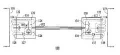
- FIG. 3is a block diagram of a cable system 100 in accordance with the present invention.
- the cable system 100includes a cable 102 , a paddle card 110 coupled to one end of the cable 102 , and a paddle card 112 coupled to the other end of the cable 102 .
- the cable 102includes a flexible wire or bundle of N wires 104 .
- One or more connection pins 114are coupled to one end of the wires 104
- one or more connection pins 116are coupled to the other end of the wires 104 .
- the connection pins 114 and 116to connect the cable (i.e. the wires 104 ) to server system nodes 118 and 119 when the paddle cards 110 and 112 are plugged into the server system nodes 118 and 119 .
- an LED circuit 120is coupled to the paddle card 110 .
- the LED circuit 120includes a voltage pin 122 , a resister 124 , an LED 126 , a diode 127 , and a ground pin 128 .
- an LED circuit 130is coupled to the paddle card 112 .
- the LED circuit 130includes a voltage pin 132 , a resistor 134 , an LED 136 , a diode 137 , and a ground pin 138 .
- the voltage at the voltage pins 122 and 132is 3.3V.
- the voltage at the voltage pins 122 and 132may vary and the specific voltage will depend on the specific application.
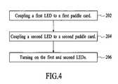
- FIG. 4is a flow chart showing a method for managing a cable in accordance with the present invention.
- the first LED 126is coupled to the paddle card 110 , in a step 202 .
- the second LED 136is coupled to the second paddle card 112 , in a step 204 .
- the first and second LEDs 126 and 136are turned on, in a step 206 .
- the LEDs being lit upi.e. in an “on” state
- the LED's being lit upcan also indicate to the user that both ends of the cable 102 are connected to their respective server system nodes 118 and 119 .
- the LEDs 126 and 136are connected across the cable 102 such that both LEDs 126 and 136 can be turned on even if one end of the cable 102 (i.e. one of the paddle cards 110 or 112 ) is not plugged in to the server system. For example, if the paddle card 110 is plugged into the server system and the paddle card 112 is not, both of the LEDs 124 and 134 will still turn on.
- the LEDscould be turned on via a service processor.
- the circuitcould be connected to an inter integrated circuit ( 12 C) device on the server, which would allow the service processor to turn the LEDs on and off.
- I 2 C deviceswhich are well known, adhere to an I 2 C protocol.
- I 2 C devicesoperate with an I 2 C bus, which is an inter IC serial 2 wire bus that provides the communications link between some integrated circuits in a system.
- the LEDscould be turned on as soon as the cable is connected to the server. In this case the LED circuit would be connected directly to Vcc and Ground on the system board.
- FIG. 5is a block diagram of a cable system 300 in accordance with another embodiment of the present invention.
- the cable system 300includes a cable 302 , a paddle card 310 coupled to one end of the cable 302 , and a paddle card 312 coupled to the other end of the cable 302 .
- the cable 302includes a flexible wire or bundle of N wires 304 .
- One or more connection pins 314are coupled to one end of the wires 304
- one or more connection pins 316are coupled to the other end of the wires 304 .
- the connection pins 314 and 316to connect the cable (i.e. the wires 304 ) to server system nodes 118 and 119 when the paddle cards 310 and 312 are plugged into the server system nodes 118 and 119 .
- an LED circuit 320is coupled to the paddle card 310 .
- the LED circuit 320includes a ground pin 322 , a resister 324 , and an LED 326 .
- An LED circuit 330is coupled to the paddle card 312 .
- the LED circuit 330includes a voltage pin 332 and an LED 136 .
- the LED circuits 320 and 330are integrated such that the LEDs 326 and 336 turn on when both of the paddle cards 310 and 312 are plugged into the server system nodes 118 and 119 .
- the voltage at the voltage pin 332is 3.3V.
- the voltage at the voltage pin 332may vary and the specific voltage will depend on the specific application.
- the LEDs coupled to each paddle cardlight up when both ends of the cable have been connected so that it can be easily and visually determined if both ends of the cable are connected.
- the present inventionprovides numerous benefits. For example, it visually identifies a cable in an environment where multiple cables of the same type are used and allows the user to determine if a cable is connected at both ends. As a result, configuration and serviceability of a server system is improved due to the ease of determining where cables are connected, particularly in server systems with multiple identical cables.
- a system and method in accordance with the present invention for locating a cable in a server systemhas been disclosed.
- the systemincludes paddle cards that are coupled to each end of the cable.
- Each paddle cardis coupled to an LED that lights up so that the ends of the cable can be visually located among a multitude of cables.
- the LEDs coupled to each paddle cardlight up when both ends of the cable have been connected so that it can be easily and visually determined if both ends of the cable are connected.
Landscapes
- Physics & Mathematics (AREA)
- General Physics & Mathematics (AREA)
- Optics & Photonics (AREA)
- Electric Cable Installation (AREA)
Abstract
Description
Claims (2)
Priority Applications (1)
| Application Number | Priority Date | Filing Date | Title |
|---|---|---|---|
| US11/101,272US7294786B2 (en) | 2005-04-06 | 2005-04-06 | System and method for managing a cable in a server system |
Applications Claiming Priority (1)
| Application Number | Priority Date | Filing Date | Title |
|---|---|---|---|
| US11/101,272US7294786B2 (en) | 2005-04-06 | 2005-04-06 | System and method for managing a cable in a server system |
Publications (2)
| Publication Number | Publication Date |
|---|---|
| US20060228090A1 US20060228090A1 (en) | 2006-10-12 |
| US7294786B2true US7294786B2 (en) | 2007-11-13 |
Family
ID=37083255
Family Applications (1)
| Application Number | Title | Priority Date | Filing Date |
|---|---|---|---|
| US11/101,272Expired - Fee RelatedUS7294786B2 (en) | 2005-04-06 | 2005-04-06 | System and method for managing a cable in a server system |
Country Status (1)
| Country | Link |
|---|---|
| US (1) | US7294786B2 (en) |
Cited By (21)
| Publication number | Priority date | Publication date | Assignee | Title |
|---|---|---|---|---|
| US20080100456A1 (en)* | 2006-10-31 | 2008-05-01 | Downie John D | System for mapping connections using RFID function |
| US7760094B1 (en) | 2006-12-14 | 2010-07-20 | Corning Cable Systems Llc | RFID systems and methods for optical fiber network deployment and maintenance |
| US7782202B2 (en) | 2006-10-31 | 2010-08-24 | Corning Cable Systems, Llc | Radio frequency identification of component connections |
| US7965186B2 (en) | 2007-03-09 | 2011-06-21 | Corning Cable Systems, Llc | Passive RFID elements having visual indicators |
| US8248208B2 (en) | 2008-07-15 | 2012-08-21 | Corning Cable Systems, Llc. | RFID-based active labeling system for telecommunication systems |
| US8264355B2 (en) | 2006-12-14 | 2012-09-11 | Corning Cable Systems Llc | RFID systems and methods for optical fiber network deployment and maintenance |
| US20120274452A1 (en)* | 2011-04-26 | 2012-11-01 | Aravind Chamarti | Radio frequency (rf)-enabled latches and related components, assemblies, systems, and methods |
| US20140022083A1 (en)* | 2012-07-20 | 2014-01-23 | Christopher D. Wells | Method and apparatus of locating current sensors |
| US8731405B2 (en) | 2008-08-28 | 2014-05-20 | Corning Cable Systems Llc | RFID-based systems and methods for collecting telecommunications network information |
| US9159012B2 (en) | 2009-11-30 | 2015-10-13 | Corning Incorporated | RFID condition latching |
| US9165232B2 (en) | 2012-05-14 | 2015-10-20 | Corning Incorporated | Radio-frequency identification (RFID) tag-to-tag autoconnect discovery, and related methods, circuits, and systems |
| US20160049220A1 (en)* | 2010-08-31 | 2016-02-18 | 3M Innovative Properties Company | Shielded electrical cable |
| US9563832B2 (en) | 2012-10-08 | 2017-02-07 | Corning Incorporated | Excess radio-frequency (RF) power storage and power sharing RF identification (RFID) tags, and related connection systems and methods |
| US9786411B2 (en) | 2010-08-31 | 2017-10-10 | 3M Innovative Properties Company | Electrical characteristics of shielded electrical cables |
| US9892823B2 (en) | 2010-08-31 | 2018-02-13 | 3M Innovative Properties Company | High density shielded electrical cable and other shielded cables, systems, and methods |
| US20180233863A1 (en)* | 2016-07-25 | 2018-08-16 | Checkall Inc. | Led lan cable connector capable of high speed data transmission, led lan cable capable of high speed data transmission, and led lan cable system capable of high speed data transmission |
| US10147522B2 (en) | 2010-08-31 | 2018-12-04 | 3M Innovative Properties Company | Electrical characteristics of shielded electrical cables |
| US10832536B2 (en) | 2018-12-07 | 2020-11-10 | International Business Machines Corporation | Guided cable management |
| US20230180423A1 (en)* | 2021-12-06 | 2023-06-08 | Motorola Solutions, Inc. | Cable assembly providing extended led interface |
| US20230260375A1 (en)* | 2022-02-14 | 2023-08-17 | Ciena Corporation | Guided Cable Assist of networking hardware |
| US20230290542A1 (en)* | 2010-08-31 | 2023-09-14 | 3M Innovative Properties Company | Shielded electric cable |
Families Citing this family (2)
| Publication number | Priority date | Publication date | Assignee | Title |
|---|---|---|---|---|
| US9230416B2 (en) | 2012-08-06 | 2016-01-05 | Finisar Corporation | Communication devices including a sensor configured to detect physical input |
| CN107819604A (en) | 2016-09-14 | 2018-03-20 | 苏州旭创科技有限公司 | Optical communication module |
Citations (23)
| Publication number | Priority date | Publication date | Assignee | Title |
|---|---|---|---|---|
| US4074187A (en) | 1976-11-30 | 1978-02-14 | Miller David H | Cable tester for multi-pair shielded cables |
| US4326162A (en) | 1980-05-02 | 1982-04-20 | Hankey James H | Cable tester with first and second interengaging test modules |
| US4384249A (en) | 1980-09-05 | 1983-05-17 | Alvaro Medina | Cable testing apparatus and method |
| US4445086A (en) | 1982-02-22 | 1984-04-24 | The Boeing Company | Multiconductor cable tester |
| US4471293A (en) | 1982-05-03 | 1984-09-11 | Otto Schnack | Multi-conductor cable test unit |
| US4890102A (en)* | 1987-05-26 | 1989-12-26 | Cabletron, Inc. | Visual display for communication network monitoring and troubleshooting |
| US4978317A (en)* | 1989-03-27 | 1990-12-18 | Alan Pocrass | Connector with visual indicator |
| US5027074A (en) | 1989-11-16 | 1991-06-25 | Premier Technologies | Cable tester |
| US5081627A (en)* | 1989-07-05 | 1992-01-14 | Casat Technologies, Inc. | Status and activity monitor for contention type local area networks |
| US5168237A (en) | 1989-10-26 | 1992-12-01 | Centre National D'etudes Des Telecommunications | Test device for a bus with two pairs of conductors |
| US5198664A (en)* | 1991-07-18 | 1993-03-30 | Banner Engineering Corporation | Photoelectric sensor assembly having compressible and sealing members |
| US5249183A (en)* | 1991-03-14 | 1993-09-28 | Level One Communications, Inc. | Interfacing unit for local area networks |
| US5428671A (en) | 1992-11-09 | 1995-06-27 | Compaq Computer Corporation | Modem for tight coupling between a computer and a cellular telephone |
| US5577023A (en) | 1992-12-01 | 1996-11-19 | Farallon Computing, Inc. | Method and apparatus for automatic configuration of a network connection |
| US5601451A (en) | 1994-03-28 | 1997-02-11 | Amphenol Corporation | Combination connector |
| US5741152A (en)* | 1995-04-25 | 1998-04-21 | Amphenol Corporation | Electrical connector with indicator lights |
| US5764043A (en)* | 1996-12-20 | 1998-06-09 | Siecor Corporation | Traceable patch cord and connector assembly and method for locating patch cord ends |
| US5847557A (en) | 1997-06-06 | 1998-12-08 | Fincher; William C. | Wire pair identification method |
| US6099349A (en) | 1999-02-23 | 2000-08-08 | Amphenol Corporation | Dual multiport RJ connector arrangement |
| US6102741A (en) | 1996-06-03 | 2000-08-15 | Amphenol Corporation | Common mode filter connector with isolation |
| WO2002052583A1 (en) | 2000-12-21 | 2002-07-04 | Bejed Inc. | Method and apparatus for tracing remote ends of networking cables |
| US6577243B1 (en)* | 1999-12-14 | 2003-06-10 | Alan J. Brown | Method and apparatus for tracing remote ends of networking cables |
| US7038135B1 (en)* | 2004-06-28 | 2006-05-02 | Avaya Technology Corp. | Embedded cable connection identification circuits |
- 2005
- 2005-04-06USUS11/101,272patent/US7294786B2/ennot_activeExpired - Fee Related
Patent Citations (23)
| Publication number | Priority date | Publication date | Assignee | Title |
|---|---|---|---|---|
| US4074187A (en) | 1976-11-30 | 1978-02-14 | Miller David H | Cable tester for multi-pair shielded cables |
| US4326162A (en) | 1980-05-02 | 1982-04-20 | Hankey James H | Cable tester with first and second interengaging test modules |
| US4384249A (en) | 1980-09-05 | 1983-05-17 | Alvaro Medina | Cable testing apparatus and method |
| US4445086A (en) | 1982-02-22 | 1984-04-24 | The Boeing Company | Multiconductor cable tester |
| US4471293A (en) | 1982-05-03 | 1984-09-11 | Otto Schnack | Multi-conductor cable test unit |
| US4890102A (en)* | 1987-05-26 | 1989-12-26 | Cabletron, Inc. | Visual display for communication network monitoring and troubleshooting |
| US4978317A (en)* | 1989-03-27 | 1990-12-18 | Alan Pocrass | Connector with visual indicator |
| US5081627A (en)* | 1989-07-05 | 1992-01-14 | Casat Technologies, Inc. | Status and activity monitor for contention type local area networks |
| US5168237A (en) | 1989-10-26 | 1992-12-01 | Centre National D'etudes Des Telecommunications | Test device for a bus with two pairs of conductors |
| US5027074A (en) | 1989-11-16 | 1991-06-25 | Premier Technologies | Cable tester |
| US5249183A (en)* | 1991-03-14 | 1993-09-28 | Level One Communications, Inc. | Interfacing unit for local area networks |
| US5198664A (en)* | 1991-07-18 | 1993-03-30 | Banner Engineering Corporation | Photoelectric sensor assembly having compressible and sealing members |
| US5428671A (en) | 1992-11-09 | 1995-06-27 | Compaq Computer Corporation | Modem for tight coupling between a computer and a cellular telephone |
| US5577023A (en) | 1992-12-01 | 1996-11-19 | Farallon Computing, Inc. | Method and apparatus for automatic configuration of a network connection |
| US5601451A (en) | 1994-03-28 | 1997-02-11 | Amphenol Corporation | Combination connector |
| US5741152A (en)* | 1995-04-25 | 1998-04-21 | Amphenol Corporation | Electrical connector with indicator lights |
| US6102741A (en) | 1996-06-03 | 2000-08-15 | Amphenol Corporation | Common mode filter connector with isolation |
| US5764043A (en)* | 1996-12-20 | 1998-06-09 | Siecor Corporation | Traceable patch cord and connector assembly and method for locating patch cord ends |
| US5847557A (en) | 1997-06-06 | 1998-12-08 | Fincher; William C. | Wire pair identification method |
| US6099349A (en) | 1999-02-23 | 2000-08-08 | Amphenol Corporation | Dual multiport RJ connector arrangement |
| US6577243B1 (en)* | 1999-12-14 | 2003-06-10 | Alan J. Brown | Method and apparatus for tracing remote ends of networking cables |
| WO2002052583A1 (en) | 2000-12-21 | 2002-07-04 | Bejed Inc. | Method and apparatus for tracing remote ends of networking cables |
| US7038135B1 (en)* | 2004-06-28 | 2006-05-02 | Avaya Technology Corp. | Embedded cable connection identification circuits |
Cited By (60)
| Publication number | Priority date | Publication date | Assignee | Title |
|---|---|---|---|---|
| US7772975B2 (en) | 2006-10-31 | 2010-08-10 | Corning Cable Systems, Llc | System for mapping connections using RFID function |
| US7782202B2 (en) | 2006-10-31 | 2010-08-24 | Corning Cable Systems, Llc | Radio frequency identification of component connections |
| US20080100456A1 (en)* | 2006-10-31 | 2008-05-01 | Downie John D | System for mapping connections using RFID function |
| US7760094B1 (en) | 2006-12-14 | 2010-07-20 | Corning Cable Systems Llc | RFID systems and methods for optical fiber network deployment and maintenance |
| US8264355B2 (en) | 2006-12-14 | 2012-09-11 | Corning Cable Systems Llc | RFID systems and methods for optical fiber network deployment and maintenance |
| US7965186B2 (en) | 2007-03-09 | 2011-06-21 | Corning Cable Systems, Llc | Passive RFID elements having visual indicators |
| US8248208B2 (en) | 2008-07-15 | 2012-08-21 | Corning Cable Systems, Llc. | RFID-based active labeling system for telecommunication systems |
| US9058529B2 (en) | 2008-08-28 | 2015-06-16 | Corning Optical Communications LLC | RFID-based systems and methods for collecting telecommunications network information |
| US8731405B2 (en) | 2008-08-28 | 2014-05-20 | Corning Cable Systems Llc | RFID-based systems and methods for collecting telecommunications network information |
| US9159012B2 (en) | 2009-11-30 | 2015-10-13 | Corning Incorporated | RFID condition latching |
| US10340059B2 (en)* | 2010-08-31 | 2019-07-02 | 3M Innovative Properties Company | Shielded electrical cable |
| US10347398B2 (en) | 2010-08-31 | 2019-07-09 | 3M Innovative Properties Company | Electrical characteristics of shielded electrical cables |
| US11854716B2 (en)* | 2010-08-31 | 2023-12-26 | 3M Innovative Properties Company | Shielded electrical cable |
| US11923112B2 (en) | 2010-08-31 | 2024-03-05 | 3M Innovative Properties Company | High density shielded electrical cable and other shielded cables, systems, and methods |
| US20160049220A1 (en)* | 2010-08-31 | 2016-02-18 | 3M Innovative Properties Company | Shielded electrical cable |
| US20230253132A1 (en)* | 2010-08-31 | 2023-08-10 | 3M Innovative Properties Company | High density shielded electrical cable and other shielded cables, systems, and methods |
| US9601236B2 (en) | 2010-08-31 | 2017-03-21 | 3M Innovative Properties Company | Shielded electrical cable |
| US9653195B2 (en)* | 2010-08-31 | 2017-05-16 | 3M Innovative Properties Company | Shielded electrical cable |
| US9786411B2 (en) | 2010-08-31 | 2017-10-10 | 3M Innovative Properties Company | Electrical characteristics of shielded electrical cables |
| US9865378B2 (en) | 2010-08-31 | 2018-01-09 | 3M Innovative Properties Company | Shielded electrical cable |
| US9892823B2 (en) | 2010-08-31 | 2018-02-13 | 3M Innovative Properties Company | High density shielded electrical cable and other shielded cables, systems, and methods |
| US12205732B2 (en)* | 2010-08-31 | 2025-01-21 | 3M Innovative Properties Company | Shielded electric cable |
| US10056170B2 (en) | 2010-08-31 | 2018-08-21 | 3M Innovative Properties Company | High density shielded electrical cable and other shielded cables, systems, and methods |
| US11699536B2 (en) | 2010-08-31 | 2023-07-11 | 3M Innovative Properties Company | High density shielded electrical cable and other shielded cables, systems, and methods |
| US10090082B2 (en) | 2010-08-31 | 2018-10-02 | 3M Innovative Properties Company | Shielded electrical cable |
| US10109396B2 (en) | 2010-08-31 | 2018-10-23 | 3M Innovative Properties Company | Electrical characteristics of shielded electrical cables |
| US10109397B2 (en) | 2010-08-31 | 2018-10-23 | 3M Innovative Properties Company | Electrical characteristics of shielded electrical cables |
| US10134506B2 (en) | 2010-08-31 | 2018-11-20 | 3M Innovative Properties Company | Electrical characteristics of shielded electrical cables |
| US10147522B2 (en) | 2010-08-31 | 2018-12-04 | 3M Innovative Properties Company | Electrical characteristics of shielded electrical cables |
| US20180374610A1 (en)* | 2010-08-31 | 2018-12-27 | 3M Innovative Properties Company | Shielded electrical cable |
| US11688530B2 (en)* | 2010-08-31 | 2023-06-27 | 3M Innovative Properties Company | Shielded electric cable |
| US20230290542A1 (en)* | 2010-08-31 | 2023-09-14 | 3M Innovative Properties Company | Shielded electric cable |
| US10347393B2 (en) | 2010-08-31 | 2019-07-09 | 3M Innovative Properties Company | High density shielded electrical cable and other shielded cables, systems, and methods |
| US10438725B2 (en) | 2010-08-31 | 2019-10-08 | 3M Innovative Properties Company | Electrical characteristics of shielded electrical cables |
| US10573432B2 (en)* | 2010-08-31 | 2020-02-25 | 3M Innovative Properties Company | Shielded electrical cable |
| US10629329B2 (en) | 2010-08-31 | 2020-04-21 | 3M Innovative Properties Company | High density shielded electrical cable and other shielded cables, systems, and methods |
| US10784021B2 (en) | 2010-08-31 | 2020-09-22 | 3M Innovative Properties Company | Shielded electrical cable |
| US12205733B2 (en) | 2010-08-31 | 2025-01-21 | 3M Innovative Properties Company | Shielded electrical cable |
| US10896772B2 (en) | 2010-08-31 | 2021-01-19 | 3M Innovative Properties Company | High density shielded electrical cable and other shielded cables, systems, and methods |
| US10998111B2 (en) | 2010-08-31 | 2021-05-04 | 3M Innovative Properties Company | Shielded electrical cable |
| US11348706B2 (en)* | 2010-08-31 | 2022-05-31 | 3M Innovative Properties Company | Shielded electrical cable |
| US20220230783A1 (en)* | 2010-08-31 | 2022-07-21 | 3M Innovative Properties Company | Shielded electric cable |
| US20220270786A1 (en)* | 2010-08-31 | 2022-08-25 | 3M Innovative Properties Company | Shielded electric cable |
| US11488745B2 (en)* | 2010-08-31 | 2022-11-01 | 3M Innovative Properties Company | Shielded electrical cable |
| US20220367087A1 (en)* | 2010-08-31 | 2022-11-17 | 3M Innovative Properties Company | Shielded electrical cable |
| US11651871B2 (en)* | 2010-08-31 | 2023-05-16 | 3M Innovative Properties Company | Shielded electric cable |
| US11664137B2 (en) | 2010-08-31 | 2023-05-30 | 3M Innovative Properties Company | High density shielded electrical cable and other shielded cables, systems, and methods |
| US20240212879A1 (en)* | 2010-08-31 | 2024-06-27 | 3M Innovative Properties Company | High density shielded electrical cable and other shielded cables, systems, and methods |
| US20120274452A1 (en)* | 2011-04-26 | 2012-11-01 | Aravind Chamarti | Radio frequency (rf)-enabled latches and related components, assemblies, systems, and methods |
| US9165232B2 (en) | 2012-05-14 | 2015-10-20 | Corning Incorporated | Radio-frequency identification (RFID) tag-to-tag autoconnect discovery, and related methods, circuits, and systems |
| US8773273B2 (en)* | 2012-07-20 | 2014-07-08 | Eaton Corporation | Method and apparatus of locating current sensors |
| US20140022083A1 (en)* | 2012-07-20 | 2014-01-23 | Christopher D. Wells | Method and apparatus of locating current sensors |
| US9563832B2 (en) | 2012-10-08 | 2017-02-07 | Corning Incorporated | Excess radio-frequency (RF) power storage and power sharing RF identification (RFID) tags, and related connection systems and methods |
| US10063019B1 (en)* | 2016-07-25 | 2018-08-28 | Checkall Inc. | LED LAN cable connector capable of high speed data transmission, LED LAN cable capable of high speed data transmission, and LED LAN cable system capable of high speed data transmission |
| US20180233863A1 (en)* | 2016-07-25 | 2018-08-16 | Checkall Inc. | Led lan cable connector capable of high speed data transmission, led lan cable capable of high speed data transmission, and led lan cable system capable of high speed data transmission |
| US10832536B2 (en) | 2018-12-07 | 2020-11-10 | International Business Machines Corporation | Guided cable management |
| US11758680B2 (en)* | 2021-12-06 | 2023-09-12 | Motorola Solutions, Inc. | Cable assembly providing extended LED interface |
| US20230180423A1 (en)* | 2021-12-06 | 2023-06-08 | Motorola Solutions, Inc. | Cable assembly providing extended led interface |
| US20230260375A1 (en)* | 2022-02-14 | 2023-08-17 | Ciena Corporation | Guided Cable Assist of networking hardware |
| US12400528B2 (en)* | 2022-02-14 | 2025-08-26 | Ciena Corporation | Guided cable assist of networking hardware |
Also Published As
| Publication number | Publication date |
|---|---|
| US20060228090A1 (en) | 2006-10-12 |
Similar Documents
| Publication | Publication Date | Title |
|---|---|---|
| US7294786B2 (en) | System and method for managing a cable in a server system | |
| US6462435B1 (en) | Cable detect and EMI reduction apparatus and method | |
| US7811119B2 (en) | Smart cable provisioning for a patch cord management system | |
| US8949496B2 (en) | Double-buffer insertion count stored in a device attached to a physical layer medium | |
| US20140038462A1 (en) | Managed fiber connectivity systems | |
| HUP0300041A2 (en) | Device for visual identification of cables or conduits | |
| US9219543B2 (en) | Monitoring optical decay in fiber connectivity systems | |
| US9081537B2 (en) | Identifier encoding scheme for use with multi-path connectors | |
| CN105191338A (en) | Systems and methods for associating location information with a communication sub-assembly housed within a communication assembly | |
| US20230140676A1 (en) | Rack controller with native support for intelligent patching equipment installed in multiple racks | |
| US20140141643A1 (en) | Patch panel assembly adapter for use with data networks | |
| US8033873B2 (en) | Patch cable physical link identification device | |
| WO2015195455A1 (en) | Selectively connecting a port of an electrical device to components in the electrical device | |
| CN105706458A (en) | Network cables including a device for visually marking them and a device for visually marking the ends of network cables | |
| KR101938757B1 (en) | Patch panel having the function of connection position indication of patch cord | |
| US20040213522A1 (en) | Fiber optic cable identification kit and its method | |
| US10891847B2 (en) | Visible indication of a port as configured to management functionality | |
| US7573353B2 (en) | Circuit topology for multiple loads | |
| CN115912597A (en) | Power supply switching circuit and Ethernet device using it | |
| US7485809B2 (en) | System and method for implementing a cable system | |
| CN104360932A (en) | High-availability extensible signal and power state indicator card | |
| WO2001077699A1 (en) | Automatic straight/crossover cable detection circuit | |
| JP2005327646A (en) | power cable | |
| KR100192866B1 (en) | Debugging card connection device of portable computer | |
| US20130049798A1 (en) | Motherboard with dual network card connectors and low signal reflectivity |
Legal Events
| Date | Code | Title | Description |
|---|---|---|---|
| AS | Assignment | Owner name:INTERNATIONAL BUSINESS MACHINES CORPORATION, NEW Y Free format text:ASSIGNMENT OF ASSIGNORS INTEREST;ASSIGNORS:ALDEREGUIA, ALFREDO;RICHTER, GRACE A.;REEL/FRAME:016550/0386 Effective date:20050302 | |
| FEPP | Fee payment procedure | Free format text:PAYOR NUMBER ASSIGNED (ORIGINAL EVENT CODE: ASPN); ENTITY STATUS OF PATENT OWNER: LARGE ENTITY | |
| FPAY | Fee payment | Year of fee payment:4 | |
| AS | Assignment | Owner name:GOOGLE INC., CALIFORNIA Free format text:ASSIGNMENT OF ASSIGNORS INTEREST;ASSIGNOR:INTERNATIONAL BUSINESS MACHINES CORPORATION;REEL/FRAME:026664/0866 Effective date:20110503 | |
| REMI | Maintenance fee reminder mailed | ||
| LAPS | Lapse for failure to pay maintenance fees | ||
| STCH | Information on status: patent discontinuation | Free format text:PATENT EXPIRED DUE TO NONPAYMENT OF MAINTENANCE FEES UNDER 37 CFR 1.362 | |
| FP | Lapsed due to failure to pay maintenance fee | Effective date:20151113 | |
| AS | Assignment | Owner name:GOOGLE LLC, CALIFORNIA Free format text:CHANGE OF NAME;ASSIGNOR:GOOGLE INC.;REEL/FRAME:044142/0357 Effective date:20170929 |