US7293816B2 - Structural rail system for supporting an overhead console - Google Patents
Structural rail system for supporting an overhead consoleDownload PDFInfo
- Publication number
- US7293816B2 US7293816B2US10/907,907US90790705AUS7293816B2US 7293816 B2US7293816 B2US 7293816B2US 90790705 AUS90790705 AUS 90790705AUS 7293816 B2US7293816 B2US 7293816B2
- Authority
- US
- United States
- Prior art keywords
- pair
- rail system
- brackets
- vehicle
- structural
- Prior art date
- Legal status (The legal status is an assumption and is not a legal conclusion. Google has not performed a legal analysis and makes no representation as to the accuracy of the status listed.)
- Expired - Fee Related, expires
Links
- 125000006850spacer groupChemical group0.000claimsdescription3
- 238000000034methodMethods0.000description4
- 238000013459approachMethods0.000description2
- 239000000463materialSubstances0.000description2
- 229910052751metalInorganic materials0.000description2
- 239000002184metalSubstances0.000description2
- 230000004308accommodationEffects0.000description1
- 238000004458analytical methodMethods0.000description1
- 238000001125extrusionMethods0.000description1
- 239000004744fabricSubstances0.000description1
- 238000009434installationMethods0.000description1
- 229910001092metal group alloyInorganic materials0.000description1
- 150000002739metalsChemical class0.000description1
- 230000036651moodEffects0.000description1
- 238000003466weldingMethods0.000description1
Images

Classifications
- B—PERFORMING OPERATIONS; TRANSPORTING
- B60—VEHICLES IN GENERAL
- B60R—VEHICLES, VEHICLE FITTINGS, OR VEHICLE PARTS, NOT OTHERWISE PROVIDED FOR
- B60R7/00—Stowing or holding appliances inside vehicle primarily intended for personal property smaller than suit-cases, e.g. travelling articles, or maps
- B60R7/04—Stowing or holding appliances inside vehicle primarily intended for personal property smaller than suit-cases, e.g. travelling articles, or maps in driver or passenger space, e.g. using racks
- B—PERFORMING OPERATIONS; TRANSPORTING
- B60—VEHICLES IN GENERAL
- B60R—VEHICLES, VEHICLE FITTINGS, OR VEHICLE PARTS, NOT OTHERWISE PROVIDED FOR
- B60R11/00—Arrangements for holding or mounting articles, not otherwise provided for
- B60R11/02—Arrangements for holding or mounting articles, not otherwise provided for for radio sets, television sets, telephones, or the like; Arrangement of controls thereof
- B60R11/0211—Arrangements for holding or mounting articles, not otherwise provided for for radio sets, television sets, telephones, or the like; Arrangement of controls thereof for record carriers apparatus, e.g. video recorders, tape players or CD players
Definitions
- the inventionrelates to in-vehicle structural systems for supporting an overhead console and accessories that are attached thereto.
- the inventionincludes a structural rail system for supporting an overhead console and associated accessories in relation to a vehicle roof.
- the vehicleis considered to have an imaginary longitudinal and lateral axis.
- the terms “right” and “left”are used in relation to a forward direction of the vehicle.
- the structural rail systemhas a pair of rail members that are spaced apart. They extend substantially in a longitudinal direction. One or more brackets are oriented substantially laterally across the pair of rails. Accessories (such as DVD's, storage compartments, lighting systems, audio controls and HVAC control modules) are attached to one or more of the lateral brackets or longitudinal rail members (collectively “rail system”).
- the overhead consolehas an interior region within which the accessories are positioned and secured to the rails or brackets, thus allowing the rails or brackets to be at the same vertical level or up/down height as the console. In this way, incursion into the head room between the head of a vehicle occupant and the vehicle headliner is substantially avoided.
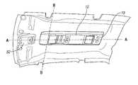
- FIG. 1is perspective view depicting an environment in which the invention is used. It illustrates an overhead console secured in position by the invention (not shown) in relation to the underside of a vehicle roof;
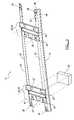
- FIG. 2is an isometric view of a structural rail system that supports the overhead console;
- FIG. 3is an isometric view of the structural rail system according to the present invention without attachment to the vehicle roof or to the overhead console. Also depicted schematically is an accessory that is attached to the rail system; and
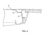
- FIG. 4is a cross-section of the right hand half of the assembly which illustrates how the invention minimizes incursion into the head room between the passenger's head and the vehicle roof.
- FIG. 1is helpful in referencing an environment in which the invention is used.
- an overhead console 12that is secured by a structural rail system 10 ( FIGS. 2-4 ) in relation to a roof bow 13 ( FIG. 4 ) within a vehicle.
- the vehiclecan be considered to have an imaginary longitudinal axis (A-A) and a lateral axis (B-B).
- the structural rail system 10includes a pair of rail members 14 , 16 that are spaced apart and extend substantially in a longitudinal direction. It will be appreciated that deviations from a parallel relationship should be considered within the scope of the invention. Further, the rail members may be spaced more closely in a forward region 39 or a rearward region 40 , or vice versa.
- brackets 18 , 20 , 22 , 24Extending laterally across the pair of rail members 14 , 16 are one or more brackets 18 , 20 , 22 , 24 . Although depicted in FIGS. 2 and 3 as 4 brackets bearing the reference numerals 18 , 20 , 22 , 24 , it should be realized that the depicted embodiment is exemplary only. In practice, for example, the brackets 18 , 20 would be combined into a unitary bracket. Similarly for the brackets 22 , 24 .
- the securing meansinclude for example, screws, nuts, rivets, heat staked plastic members, clips, and the like.
- holessuch as openings 37 , 38 can be provided to the brackets or rail members to reduce weight and material costs.
- the means for securing 36or holes comprise four such means.
- the means for securing 36are positioned proximate the forward and rear regions 38 , 40 of the pair 14 , 16 of rail members.
- At least one of the brackets 18 , 20 , 22 , 24is provided with means 42 for attaching accessories 26 to the one or more brackets.
- the means for attachingmay be embodied, for example, in screws, nuts, bolts, rivets, heat staked plastic members, clips and the like.
- At least one of the pair of rail members 14 , 16comprises a flange 44 that is affixed by a security means 36 to the vehicle roof bow 13 .
- a riser portion 46 and a bottom section 48Extending downwardly from the flange 44 is a riser portion 46 and a bottom section 48 .
- the one or more bracketsare attached to the flange 44 .
- the flange 44engages the vehicle roof bow 13 .
- the bottom flange 48is used as a bearing surface to which is attached the overhead console 12 .
- Attachmentcan be in the form of screws, bolts, heat stakes, clips and the like.
- the pair of rail members 14 , 16can be provided with curved sections 50 ( FIG. 2 ) that are curved in a longitudinal direction.
- the curved sections 50may also be contoured such that they have a flange 44 that is shaped in a direction that lies parallel to the lateral axis B-B of the vehicle.
- Finite element analyseshave been conducted on the overhead console when it supports a DVD assembly in order to evaluate dynamic response.
- a 900 Newton loadwas vertically applied to a rigid fixture and then to the assembly as installed in a vehicle.
- the maximum plastic strains in any iterationwere observed to be very small compared to failure strains.
- the loads imposedwere below the yield point.
- One way of practicing the present inventionis to assemble the accessories and console following these process steps:
- a spacer 52 bar( FIG. 4 ) can be installed between the flange 44 and the vehicle roof bow 13 .
- additional clearanceis provided between the pair of rail members 14 , 16 and the vehicle roof 13 .
- the overhead console 12is provided with a concave interior region within which at least some of the accessories 26 are positioned.
- the structural rail system 10is installed within the console 12 for attachment to the vehicle roof bow 13 , longitudinally extending edges of the console 12 extend over the riser portion 46 and bottom section 48 of the pair of rail members 14 .
- overhead consoleas used herein and as depicted in FIGS. 1-2 should be construed to mean not only the console that is positioned as shown in FIG. 1 , but also the possibility of a forwardly located console such as that depicted in FIG. 1 by the reference numeral 52 .
- the term “console”may also refer to roof-mounted structures that are located aft of the overhead console 12 depicted in FIG. 1 .
- the inventionprovides a system for providing structural support to an overhead console in which various accessories may be installed if firm support is required without excessive bulk or incursion into the available head room.
- the structural rail systemis located inside a console bezel. It is below the “A” or cloth surface of the headliner.
Landscapes
- Engineering & Computer Science (AREA)
- Mechanical Engineering (AREA)
- Multimedia (AREA)
- Vehicle Step Arrangements And Article Storage (AREA)
- Fittings On The Vehicle Exterior For Carrying Loads, And Devices For Holding Or Mounting Articles (AREA)
Abstract
Description
Claims (13)
Priority Applications (3)
| Application Number | Priority Date | Filing Date | Title |
|---|---|---|---|
| US10/907,907US7293816B2 (en) | 2005-04-20 | 2005-04-20 | Structural rail system for supporting an overhead console |
| DE102006016013ADE102006016013B4 (en) | 2005-04-20 | 2006-04-05 | Structure rail system for holding an overhead console |
| GB0607423AGB2425292B (en) | 2005-04-20 | 2006-04-13 | Structural rail system for supporting an overhead console |
Applications Claiming Priority (1)
| Application Number | Priority Date | Filing Date | Title |
|---|---|---|---|
| US10/907,907US7293816B2 (en) | 2005-04-20 | 2005-04-20 | Structural rail system for supporting an overhead console |
Publications (2)
| Publication Number | Publication Date |
|---|---|
| US20060237984A1 US20060237984A1 (en) | 2006-10-26 |
| US7293816B2true US7293816B2 (en) | 2007-11-13 |
Family
ID=36571753
Family Applications (1)
| Application Number | Title | Priority Date | Filing Date |
|---|---|---|---|
| US10/907,907Expired - Fee RelatedUS7293816B2 (en) | 2005-04-20 | 2005-04-20 | Structural rail system for supporting an overhead console |
Country Status (3)
| Country | Link |
|---|---|
| US (1) | US7293816B2 (en) |
| DE (1) | DE102006016013B4 (en) |
| GB (1) | GB2425292B (en) |
Families Citing this family (2)
| Publication number | Priority date | Publication date | Assignee | Title |
|---|---|---|---|---|
| US7219942B2 (en)* | 2004-11-05 | 2007-05-22 | Audiovox Corporation | Overhead system attachable to a rail assembly in a vehicle and method for installing same |
| FR2998533B1 (en)* | 2012-11-27 | 2014-12-26 | Renault Sa | ROOF STRUCTURE OF A MOTOR VEHICLE |
Citations (36)
| Publication number | Priority date | Publication date | Assignee | Title |
|---|---|---|---|---|
| JPS60226338A (en) | 1984-04-26 | 1985-11-11 | Honda Motor Co Ltd | Speaker device for both inside and outside the car |
| JPS6181839A (en) | 1984-08-27 | 1986-04-25 | Honda Motor Co Ltd | Speaker device for both inside and outside the car |
| US4818010A (en)* | 1986-10-17 | 1989-04-04 | Automotive Prototypes & Equipment | Mounting system for equipment in police vehicles |
| US4867498A (en)* | 1988-12-02 | 1989-09-19 | Chivas Products Limited | Overhead console assembly |
| US5094316A (en) | 1990-09-18 | 1992-03-10 | Top Source, Inc. | Overhead speaker system for use in vehicles |
| US5398856A (en)* | 1994-06-03 | 1995-03-21 | Shyu; Jenn-Shyong | Tissue rack for automobiles |
| US5575500A (en) | 1994-10-07 | 1996-11-19 | Toyota Jidosha Kabushiki Kaisha | Occupant protecting structures of vehicle body upper portions |
| US5605353A (en) | 1995-08-09 | 1997-02-25 | General Motors Corporation | Vehicle chassis with energy management |
| US5725271A (en) | 1997-01-23 | 1998-03-10 | Ford Global Technologies, Inc. | Energy absorbing automotive vehicle body structure |
| US5775762A (en)* | 1997-02-27 | 1998-07-07 | Vitito; Christopher J. | Overhead console having flip-down monitor |
| US5820204A (en) | 1994-08-31 | 1998-10-13 | Fuji Jukogyo Kabushiki Kaisha | Body structure for a motor vehicle |
| US5988678A (en) | 1996-08-02 | 1999-11-23 | Honda Giken Kogyo Kabushiki Kaisha | Structure for mounting of internal part for vehicle |
| US6024262A (en)* | 1998-06-30 | 2000-02-15 | The United States Of America As Represented By The Secretary Of The Army | Equipment mounting rack |
| US6092704A (en)* | 1997-01-15 | 2000-07-25 | Baumeister; Joseph A. | Bag and accessory handling system |
| US6115086A (en)* | 1996-08-16 | 2000-09-05 | Rosen Products Llc | Automotive display unit |
| US6145908A (en) | 1998-05-11 | 2000-11-14 | Ford Global Technologies, Inc. | Energy absorbing continuously compliant swept arch for interior trim |
| US6168204B1 (en) | 1999-03-12 | 2001-01-02 | Dana Corporation | Vehicle frame assembly having integral support surfaces |
| US6173990B1 (en) | 1997-09-26 | 2001-01-16 | Toyota Jidosha Kabushiki Kaisha | Interior equipment mounting structure for a vehicle incorporating head-protecting air bag body |
| US6189930B1 (en) | 1999-08-03 | 2001-02-20 | Dana Corporation | Joint between side rail and cross member in a vehicle frame assembly |
| US6339455B1 (en)* | 1999-12-29 | 2002-01-15 | William L. Allan | Digital video disc vehicle television |
| US6338517B1 (en)* | 2000-01-20 | 2002-01-15 | Lear Corporation | Overhead console for a vehicle |
| US6416027B1 (en)* | 2001-02-28 | 2002-07-09 | James K. Hart | Apparatus for retracting a television to a stored position and extending the television to a viewing position |
| US20020163219A1 (en)* | 2001-05-01 | 2002-11-07 | Clark Kenneth M. | Modular system for a vehicle |
| US20030168875A1 (en)* | 2001-05-01 | 2003-09-11 | Johnson Controls Technology Company | Modular system for a vehicle |
| US6685257B1 (en) | 2002-04-18 | 2004-02-03 | Johnson Controls Technology Company | Extrusion for the siderail of a vehicle to provide head impact countermeasure and support for siderail components |
| WO2004020249A2 (en) | 2002-08-27 | 2004-03-11 | Johnson Controls Technology Company | Transparent vehicle roof with arrangement for receiving articles |
| US20040084920A1 (en)* | 2001-05-01 | 2004-05-06 | Johnson Controls Technology Company | Security system for a modular system in a vehicle |
| US6749244B1 (en)* | 2002-12-27 | 2004-06-15 | Lear Corporation | Overhead storage system for a motor vehicle |
| US20040160087A1 (en)* | 2003-02-18 | 2004-08-19 | Tiesler John M. | Console for motor vehicles |
| US6824185B2 (en)* | 2003-02-28 | 2004-11-30 | Lear Corporation | Modular overhead console assembly |
| US20040256875A1 (en)* | 2003-01-30 | 2004-12-23 | Mccauley Alvin D. | Luggage loft assembly and installation method |
| WO2005061278A2 (en) | 2003-12-11 | 2005-07-07 | Johnson Controls Technology Company | Attachment system for modules in a vehicle |
| US6926333B2 (en)* | 2003-12-22 | 2005-08-09 | Lear Corporation | Modular overhead console assembly |
| US6957839B1 (en)* | 2004-09-24 | 2005-10-25 | Lear Corporation | Overhead console assembly |
| US6971699B2 (en)* | 2003-12-01 | 2005-12-06 | Ford Motor Company | Modular vehicle rail system for vehicle |
| US7055882B2 (en)* | 2004-01-08 | 2006-06-06 | Grupo Antolin Ingenieria, S.A. | Support structure for an interior overhead console or panoramic roofs of automotive vehicles |
Family Cites Families (1)
| Publication number | Priority date | Publication date | Assignee | Title |
|---|---|---|---|---|
| US20070290014A1 (en)* | 2003-07-30 | 2007-12-20 | Johnson Controls Technology Company | Positioning System for Modules in a Vehicle |
- 2005
- 2005-04-20USUS10/907,907patent/US7293816B2/ennot_activeExpired - Fee Related
- 2006
- 2006-04-05DEDE102006016013Apatent/DE102006016013B4/ennot_activeExpired - Fee Related
- 2006-04-13GBGB0607423Apatent/GB2425292B/ennot_activeExpired - Fee Related
Patent Citations (40)
| Publication number | Priority date | Publication date | Assignee | Title |
|---|---|---|---|---|
| JPS60226338A (en) | 1984-04-26 | 1985-11-11 | Honda Motor Co Ltd | Speaker device for both inside and outside the car |
| JPS6181839A (en) | 1984-08-27 | 1986-04-25 | Honda Motor Co Ltd | Speaker device for both inside and outside the car |
| US4818010A (en)* | 1986-10-17 | 1989-04-04 | Automotive Prototypes & Equipment | Mounting system for equipment in police vehicles |
| US4867498A (en)* | 1988-12-02 | 1989-09-19 | Chivas Products Limited | Overhead console assembly |
| US5094316A (en) | 1990-09-18 | 1992-03-10 | Top Source, Inc. | Overhead speaker system for use in vehicles |
| US5398856A (en)* | 1994-06-03 | 1995-03-21 | Shyu; Jenn-Shyong | Tissue rack for automobiles |
| US5820204A (en) | 1994-08-31 | 1998-10-13 | Fuji Jukogyo Kabushiki Kaisha | Body structure for a motor vehicle |
| US5575500A (en) | 1994-10-07 | 1996-11-19 | Toyota Jidosha Kabushiki Kaisha | Occupant protecting structures of vehicle body upper portions |
| US5605353A (en) | 1995-08-09 | 1997-02-25 | General Motors Corporation | Vehicle chassis with energy management |
| US5988678A (en) | 1996-08-02 | 1999-11-23 | Honda Giken Kogyo Kabushiki Kaisha | Structure for mounting of internal part for vehicle |
| US6115086A (en)* | 1996-08-16 | 2000-09-05 | Rosen Products Llc | Automotive display unit |
| US6092704A (en)* | 1997-01-15 | 2000-07-25 | Baumeister; Joseph A. | Bag and accessory handling system |
| US5725271A (en) | 1997-01-23 | 1998-03-10 | Ford Global Technologies, Inc. | Energy absorbing automotive vehicle body structure |
| US5775762A (en)* | 1997-02-27 | 1998-07-07 | Vitito; Christopher J. | Overhead console having flip-down monitor |
| US5927784A (en)* | 1997-02-27 | 1999-07-27 | Vitito; Christopher J. | Two-piece overhead console |
| US6173990B1 (en) | 1997-09-26 | 2001-01-16 | Toyota Jidosha Kabushiki Kaisha | Interior equipment mounting structure for a vehicle incorporating head-protecting air bag body |
| US6145908A (en) | 1998-05-11 | 2000-11-14 | Ford Global Technologies, Inc. | Energy absorbing continuously compliant swept arch for interior trim |
| US6024262A (en)* | 1998-06-30 | 2000-02-15 | The United States Of America As Represented By The Secretary Of The Army | Equipment mounting rack |
| US6168204B1 (en) | 1999-03-12 | 2001-01-02 | Dana Corporation | Vehicle frame assembly having integral support surfaces |
| US6189930B1 (en) | 1999-08-03 | 2001-02-20 | Dana Corporation | Joint between side rail and cross member in a vehicle frame assembly |
| US6339455B1 (en)* | 1999-12-29 | 2002-01-15 | William L. Allan | Digital video disc vehicle television |
| US6338517B1 (en)* | 2000-01-20 | 2002-01-15 | Lear Corporation | Overhead console for a vehicle |
| US6416027B1 (en)* | 2001-02-28 | 2002-07-09 | James K. Hart | Apparatus for retracting a television to a stored position and extending the television to a viewing position |
| US6827384B2 (en)* | 2001-05-01 | 2004-12-07 | Johnson Controls Technology Company | Modular system for a vehicle |
| US20020163219A1 (en)* | 2001-05-01 | 2002-11-07 | Clark Kenneth M. | Modular system for a vehicle |
| US20030168875A1 (en)* | 2001-05-01 | 2003-09-11 | Johnson Controls Technology Company | Modular system for a vehicle |
| US6669260B2 (en)* | 2001-05-01 | 2003-12-30 | Johnson Controls Technology Company | Modular system for a vehicle |
| US20040084920A1 (en)* | 2001-05-01 | 2004-05-06 | Johnson Controls Technology Company | Security system for a modular system in a vehicle |
| US6685257B1 (en) | 2002-04-18 | 2004-02-03 | Johnson Controls Technology Company | Extrusion for the siderail of a vehicle to provide head impact countermeasure and support for siderail components |
| WO2004020249A2 (en) | 2002-08-27 | 2004-03-11 | Johnson Controls Technology Company | Transparent vehicle roof with arrangement for receiving articles |
| US7097225B2 (en)* | 2002-08-27 | 2006-08-29 | Johnson Controls Technology Company | Transparent vehicle roof with arrangement for receiving articles |
| US6749244B1 (en)* | 2002-12-27 | 2004-06-15 | Lear Corporation | Overhead storage system for a motor vehicle |
| US20040256875A1 (en)* | 2003-01-30 | 2004-12-23 | Mccauley Alvin D. | Luggage loft assembly and installation method |
| US20040160087A1 (en)* | 2003-02-18 | 2004-08-19 | Tiesler John M. | Console for motor vehicles |
| US6824185B2 (en)* | 2003-02-28 | 2004-11-30 | Lear Corporation | Modular overhead console assembly |
| US6971699B2 (en)* | 2003-12-01 | 2005-12-06 | Ford Motor Company | Modular vehicle rail system for vehicle |
| WO2005061278A2 (en) | 2003-12-11 | 2005-07-07 | Johnson Controls Technology Company | Attachment system for modules in a vehicle |
| US6926333B2 (en)* | 2003-12-22 | 2005-08-09 | Lear Corporation | Modular overhead console assembly |
| US7055882B2 (en)* | 2004-01-08 | 2006-06-06 | Grupo Antolin Ingenieria, S.A. | Support structure for an interior overhead console or panoramic roofs of automotive vehicles |
| US6957839B1 (en)* | 2004-09-24 | 2005-10-25 | Lear Corporation | Overhead console assembly |
Non-Patent Citations (1)
| Title |
|---|
| Search Report under Section 17, Application No. GB0607423.1, Jul. 18, 2006. |
Also Published As
| Publication number | Publication date |
|---|---|
| GB0607423D0 (en) | 2006-05-24 |
| GB2425292A (en) | 2006-10-25 |
| GB2425292B (en) | 2007-08-01 |
| US20060237984A1 (en) | 2006-10-26 |
| DE102006016013B4 (en) | 2008-10-02 |
| DE102006016013A1 (en) | 2006-10-26 |
Similar Documents
| Publication | Publication Date | Title |
|---|---|---|
| US7874565B2 (en) | Running board bracket | |
| US8690216B2 (en) | Vehicle security partition | |
| US6851742B1 (en) | Cast alloy instrument panel beams | |
| US8177275B2 (en) | Partition for vehicle cargo area | |
| US8104819B2 (en) | Audio bracket fore and aft slip plane | |
| US8011687B2 (en) | Air bag module, air bag module arrangement, and method of fastening | |
| US20080061604A1 (en) | Modular vehicle headliner | |
| US20190126836A1 (en) | Cargo storage system for a vehicle | |
| US8500183B2 (en) | Wall and roof liner for installation in a cargo vehicle | |
| US7293816B2 (en) | Structural rail system for supporting an overhead console | |
| SE514855C2 (en) | Vehicle protection device | |
| CN113302114B (en) | Structural frame for a body of a motor vehicle | |
| CN110712687A (en) | Motor vehicle floor assembly | |
| JP2007269231A (en) | Instrument panel mounting structure | |
| CN108001544B (en) | Instrument panel and front cowl attachment | |
| JPH09301075A (en) | Automobile side step | |
| JP4482817B2 (en) | Instrument panel unit | |
| US20230158986A1 (en) | Divider panel system for vehicle | |
| JPS6243891Y2 (en) | ||
| RU2217328C2 (en) | Vehicle instrument panel | |
| JP2003237633A (en) | Steering beam for vehicle | |
| CN118201801A (en) | Vehicle seat | |
| JP2008308046A (en) | Baggage rack in vehicle | |
| JP2008149867A (en) | Assist grip for back seat | |
| JP2005255046A (en) | Vehicle body structure |
Legal Events
| Date | Code | Title | Description |
|---|---|---|---|
| AS | Assignment | Owner name:LEAR CORPORATION, MICHIGAN Free format text:ASSIGNMENT OF ASSIGNORS INTEREST;ASSIGNORS:STONE, JAY;NIEDZWIECKI, MARK;TIESLER, JOHN M.;AND OTHERS;REEL/FRAME:015924/0045;SIGNING DATES FROM 20050401 TO 20050418 | |
| AS | Assignment | Owner name:INTERNATIONAL AUTOMOTIVE COMPONENTS GROUP NORTH AM Free format text:ASSIGNMENT OF ASSIGNORS INTEREST;ASSIGNOR:LEAR CORPORATION;REEL/FRAME:019215/0727 Effective date:20070427 | |
| STCF | Information on status: patent grant | Free format text:PATENTED CASE | |
| AS | Assignment | Owner name:GENERAL ELECTRIC CAPITAL CORPORATION, AS AGENT, CO Free format text:SECURITY INTEREST;ASSIGNOR:INTERNATIONAL AUTOMOTIVE COMPONENTS GROUP NORTH AMERICA, INC;REEL/FRAME:025845/0193 Effective date:20101110 Owner name:GENERAL ELECTRIC CAPITAL CORPORATION, AS AGENT, CO Free format text:SECURITY AGREEMENT;ASSIGNOR:INTERNATIONAL AUTOMOTIVE COMPONENTS GROUP NORTH AMERICA, INC.;REEL/FRAME:025882/0019 Effective date:20101110 | |
| XAS | Not any more in us assignment database | Free format text:SECURITY INTEREST;ASSIGNOR:INTERNATIONAL AUTOMOTIVE COMPONENTS GROUP NORTH AMERICA, INC;REEL/FRAME:025845/0193 | |
| FPAY | Fee payment | Year of fee payment:4 | |
| AS | Assignment | Owner name:THE BANK OF NEW YORK MELLON, AS COLLATERAL AGENT, Free format text:SECURITY AGREEMENT;ASSIGNOR:INTERNATIONAL AUTOMOTIVE COMPONENTS GROUP NORTH AMERICA, INC., A DELAWARE CORPORATION;REEL/FRAME:026404/0069 Effective date:20110603 | |
| FPAY | Fee payment | Year of fee payment:8 | |
| AS | Assignment | Owner name:CF LENDING, LLC , AS ADMINISTRATIVE AGENT, CONNECT Free format text:SECURITY INTEREST;ASSIGNOR:INTERNATIONAL AUTOMOTIVE COMPONENTS GROUP NORTH AMERICA, INC., AS GRANTOR;REEL/FRAME:036722/0440 Effective date:20150930 Owner name:CF LENDING, LLC , AS ADMINISTRATIVE AGENT, CONNECT Free format text:SECURITY INTEREST;ASSIGNOR:INTERNATIONAL AUTOMOTIVE COMPONENTS GROUP NORTH AMERICA, INC., AS GRANTOR;REEL/FRAME:036722/0294 Effective date:20150930 | |
| AS | Assignment | Owner name:THE BANK OF NEW YORK MELLON, AS COLLATERAL AGENT, Free format text:SECURITY AGREEMENT;ASSIGNOR:INTERNATIONAL AUTOMOTIVE COMPONENTS GROUP NORTH AMERICA, INC.;REEL/FRAME:036742/0576 Effective date:20150930 | |
| AS | Assignment | Owner name:INTERNATIONAL AUTOMOTIVE COMPONENTS GROUP NORTH AM Free format text:RELEASE BY SECURED PARTY;ASSIGNOR:GENERAL ELECTRIC CAPITAL CORPORATION, AS COLLATERAL AGENT;REEL/FRAME:036777/0904 Effective date:20150930 Owner name:INTERNATIONAL AUTOMOTIVE COMPONENTS GROUP NORTH AM Free format text:RELEASE BY SECURED PARTY;ASSIGNOR:THE BANK OF NEW YORK MELLON;REEL/FRAME:036777/0821 Effective date:20150930 | |
| AS | Assignment | Owner name:CORTLAND CAPITAL MARKET SERVICES LLC, ILLINOIS Free format text:SECURITY INTEREST;ASSIGNOR:INTERNATIONAL AUTOMOTIVE COMPONENTS GROUP NORTH AMERICA, INC.;REEL/FRAME:045998/0550 Effective date:20180423 | |
| AS | Assignment | Owner name:INTERNATIONAL AUTOMOTIVE COMPONENTS GROUP NORTH AM Free format text:RELEASE OF SECURITY INTEREST IN PATENTS AT REEL 036742/FRAME 0576;ASSIGNOR:THE BANK OF NEW YORK MELLON, AS COLLATERAL AGENT;REEL/FRAME:046022/0599 Effective date:20180423 | |
| AS | Assignment | Owner name:WELLS FARGO BANK, N.A., AS ADMINISTRATIVE AGENT, M Free format text:PATENT SECURITY AGREEMENT (CANADIAN OBLIGATIONS);ASSIGNOR:INTERNATIONAL AUTOMOTIVE COMPONENTS GROUP NORTH AMERICA, INC.;REEL/FRAME:046674/0610 Effective date:20180724 | |
| FEPP | Fee payment procedure | Free format text:MAINTENANCE FEE REMINDER MAILED (ORIGINAL EVENT CODE: REM.); ENTITY STATUS OF PATENT OWNER: LARGE ENTITY | |
| LAPS | Lapse for failure to pay maintenance fees | Free format text:PATENT EXPIRED FOR FAILURE TO PAY MAINTENANCE FEES (ORIGINAL EVENT CODE: EXP.); ENTITY STATUS OF PATENT OWNER: LARGE ENTITY | |
| STCH | Information on status: patent discontinuation | Free format text:PATENT EXPIRED DUE TO NONPAYMENT OF MAINTENANCE FEES UNDER 37 CFR 1.362 | |
| FP | Lapsed due to failure to pay maintenance fee | Effective date:20191113 | |
| AS | Assignment | Owner name:INTERNATIONAL AUTOMOTIVE COMPONENTS GROUP NORTH AMERICA, INC., MICHIGAN Free format text:TERMINATION AND RELEASE OF INTELLECTUAL PROPERTY SECURITY AGREEMENTS;ASSIGNOR:WELLS FARGO BANK, N.A.;REEL/FRAME:067853/0742 Effective date:20240620 |