US7293465B2 - Conveyor diagnostic system having local positioning system - Google Patents
Conveyor diagnostic system having local positioning systemDownload PDFInfo
- Publication number
- US7293465B2 US7293465B2US11/221,625US22162505AUS7293465B2US 7293465 B2US7293465 B2US 7293465B2US 22162505 AUS22162505 AUS 22162505AUS 7293465 B2US7293465 B2US 7293465B2
- Authority
- US
- United States
- Prior art keywords
- line assembly
- conveyor line
- sensor component
- loading
- conveyor
- Prior art date
- Legal status (The legal status is an assumption and is not a legal conclusion. Google has not performed a legal analysis and makes no representation as to the accuracy of the status listed.)
- Active, expires
Links
Images


Classifications
- B—PERFORMING OPERATIONS; TRANSPORTING
- B65—CONVEYING; PACKING; STORING; HANDLING THIN OR FILAMENTARY MATERIAL
- B65G—TRANSPORT OR STORAGE DEVICES, e.g. CONVEYORS FOR LOADING OR TIPPING, SHOP CONVEYOR SYSTEMS OR PNEUMATIC TUBE CONVEYORS
- B65G43/00—Control devices, e.g. for safety, warning or fault-correcting
- B—PERFORMING OPERATIONS; TRANSPORTING
- B65—CONVEYING; PACKING; STORING; HANDLING THIN OR FILAMENTARY MATERIAL
- B65G—TRANSPORT OR STORAGE DEVICES, e.g. CONVEYORS FOR LOADING OR TIPPING, SHOP CONVEYOR SYSTEMS OR PNEUMATIC TUBE CONVEYORS
- B65G17/00—Conveyors having an endless traction element, e.g. a chain, transmitting movement to a continuous or substantially-continuous load-carrying surface or to a series of individual load-carriers; Endless-chain conveyors in which the chains form the load-carrying surface
- B—PERFORMING OPERATIONS; TRANSPORTING
- B65—CONVEYING; PACKING; STORING; HANDLING THIN OR FILAMENTARY MATERIAL
- B65G—TRANSPORT OR STORAGE DEVICES, e.g. CONVEYORS FOR LOADING OR TIPPING, SHOP CONVEYOR SYSTEMS OR PNEUMATIC TUBE CONVEYORS
- B65G2203/00—Indexing code relating to control or detection of the articles or the load carriers during conveying
- B65G2203/02—Control or detection
- B65G2203/0266—Control or detection relating to the load carrier(s)
- B65G2203/0283—Position of the load carrier
Definitions
- the present inventionrelates generally to a conveyor diagnostic system and, more specifically, to a conveyor diagnostic system having a local positioning system.
- conveyor line assembliesinclude moving parts, such as chains, rollers, and the like that undergo a significant amount of loading during operation. These loads may vary over time or may be concentrated in certain areas of the conveyor line assembly. For instance, loads on the conveyor line assembly can increase over the operating life of the assembly. Likewise, load concentrations can develop due to structural misalignment, wear, or lack of proper lubrication of certain components of the conveyor line assembly. Such loading can cause the conveyor line assembly to malfunction or fail, which can lead to losses in productivity.
- Conveyor diagnostic systemshave been designed for measuring and monitoring these loads.
- Typical systemsmeasure loading by using strain gauges that are coupled to chain links of the conveyor line assembly. The loads are monitored to thereby properly maintain and preferably avoid failure of the conveyor.
- the present inventionovercomes the disadvantages of the related art in a conveyor diagnostic system for monitoring loading of a conveyor line assembly.
- the conveyor diagnostic systemincludes at least one sensor component coupled to the conveyor line assembly.
- the sensor componentis adapted for detecting loading of the conveyor line assembly and is further adapted for generating and transmitting a signal that is correlative of the loading of the conveyor line assembly.
- the conveyor diagnostic systemalso includes a ground station adapted to receive and process the signal that is correlative of the loading of the conveyor line assembly.
- the conveyor diagnostic systemincludes a local positioning system that is adapted for detecting the location of the sensor component in relation to a reference point.
- the present inventionis a method of monitoring a conveyor line assembly that involves detecting loading of the conveyor line assembly using at least one sensor component coupled to the conveyor line assembly. The method also involves generating a signal that correlates to the loading of the conveyor line assembly. Furthermore, the method involves processing the signal that correlates to the loading of the conveyor line assembly. In addition, the method involves locating the at least one sensor component in relation to a reference point to thereby analyze an identified portion of the conveyor line assembly.
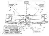
- FIG. 1is a schematic illustration of a portion of a conveyor line assembly with a conveyor diagnostic system of the present invention.
- FIG. 2is a top view of a chain link of a conveyor chain having a sensor array for measuring loading of the chain link.
- the conveyor line assembly 10includes a conveyor chain 12 having at least one—and preferably a plurality—of chain links.
- the conveyor chain 12includes a plurality of dual links 14 and a plurality of single links 16 coupled in alternating manner by pins 18 .
- the conveyor line assembly 10also includes a carrier assembly 20 for movably supporting the chain 12 .
- the carrier assembly 20includes trolleys 22 having an upper portion 24 , an intermediate portion 26 , and a lower portion 28 .
- the upper portion 24 of each trolley 22is pivotally coupled to a roller 30 , and the roller 30 is rotationally supported by a beam 32 .
- the intermediate portion 26 of each trolley 22is coupled in any suitable manner to one of the single links 16 of the conveyor chain 12 .
- the lower portion 28 of each trolley 22can be used to support an article for moving the article along an assembly line.
- the conveyor line assembly 10also includes a conveyor diagnostic system 34 for monitoring loading of the conveyor line assembly 10 .
- the conveyor diagnostic system 34includes at least one sensor component 36 shown in detail in FIG. 2 .
- the sensor component 36is coupled to one of the single links 16 of the conveyor chain 12 and can detect loading of the corresponding single link 16 .
- the sensor component 36could be coupled anywhere along the conveyor chain 12 or to any other suitable component of the conveyor line assembly 10 without departing from the scope of the present invention.
- the conveyor diagnostic system 34could include a plurality of sensor components 36 , each coupled to individual links 16 , without departing from the scope of the invention.
- the sensor component 36is disposed inside the single link 16 for detecting loading of that link 16 as it moves along the conveyor line assembly 10 .
- the sensor component 36is of a type disclosed in Applicant's U.S. Pat. No. 6,865,955, which is hereby incorporated by reference in its entirety.
- the sensor component 36includes a plurality of sub-structures 37 a , 37 b , 37 c , 37 d mounted to the link 16 and includes a circuit having a plurality of strain gauges wired into a Wheatstone Bridge.
- the plurality of strain gaugesgenerates a signal that correlates to the loading of the link 16 . More specifically, mechanical loading of the link 16 causes resistance changes in the strain gauges such that an electrical signal is generated.
- the sensor component 36is adapted for detecting multiple loading types including tension, bending, and torsion loads in the link 16 .
- the sensor component 36can detect multi-axial loading in the link 16 . More specifically, as shown in FIG. 2 , the link 16 defines three axes (labeled X, Y, and Z), and the sensor component 36 can detect axial loads along any of these axes, bending loads about any of these axes, and/or torsion loads about any of these axes.
- the strain gauges of the sub-structure 37 aare oriented to primarily detect tension loading along the Z axis
- the strain gauges of the substructure 37 bare oriented to primarily detect bending loads about the X axis
- the strain gauges of the substructure 37 care oriented to primarily detect bending loads about the Y axis
- the strain gauges of the substructure 37 dare orientated primarily detect bending (torsional) loads about the Z axis.
- each substructure 37 a , 37 b , 37 c , 37 dare oriented to be sensitive enough in the direction of the load component it is measuring and stiff enough in all other directions to minimize the influence on the overall stiffness of link 16 .
- the sensor component 36also compensates for temperature effects as well as cancellation of signals caused by extraneous loading such as the other loads measured by the other substructures 37 a , 37 b , 37 c , 37 d . Accordingly, the sensor component 36 can detect and measure the loading of the link 16 more precisely for improved analysis of the loading on the conveyor line assembly 10 as will be discussed in greater detail below.
- the link 16can include any number of substructures 37 a , 37 b , 37 c , 37 d and that the substructures can be oriented to detect any type of load with respect to any axis depending on the application of the conveyor diagnostic system 34 .
- the sensor component 36is also adapted for transmitting the signal that correlates to the detected loading of the link 16 .
- the sensor component 36is electrically connected to a transceiver 38 with a sensor antenna 39 that transmits and receives RF signals.
- the transceiver 38transmits signals that correlate to the loading of the link 16 and also receives command signals that affect the operation of the sensor component 36 as will be discussed in greater detail below.
- the conveyor diagnostic system 34further includes a ground station 42 that generally receives and processes the signals generated and transmitted by the sensor component 36 .
- the ground station 42includes a processor 44 , a controller 46 , and a database 48 .
- the controller 46generates control signals that control the operation of the conveyor diagnostic system 34
- the processor 44processes data supplied by the sensor component 36
- the database 48provides information regarding the conveyor line assembly 10 to a user based on the processed data.
- the processor 44 , controller 46 , and database 48can be electrically connected in any suitable manner.
- the processor 44 , controller 46 , and database 48are included in a computer.
- the conveyor diagnostic system 34also includes an intermediate communicator 50 .
- the intermediate communicator 50receives the RF signals from the sensor component 36 and in turn transmits correlative signals to the ground station 42 .
- the intermediate communicator 50includes appropriate circuitry and an intermediate antenna 52 .
- the ground station 42includes appropriate circuitry and a ground antenna 54 .
- RF signals transmitted from the sensor antenna 39are received by the intermediate antenna 52 of the intermediate communicator 50 , which in turn transmits correlative RF signals to the ground station 42 via the intermediate antenna 52 .
- Those signalsare received by the ground station 42 via the ground antenna 54 .
- the sensor component 36 , the intermediate communicator 50 , and the ground station 42can each be disposed remotely from each other and yet those components can still effectively communicate. This can be especially advantageous in situations where the link 16 , and thus the sensor component 36 , moves a relatively far distance away from the ground station 42 .
- the sensor component 36could directly communicate with the ground station 42 without an intermediate communicator 50 without departing from the scope of the invention. It should also be appreciated that the sensor component 36 , the intermediate communicator 50 , and the ground station 42 could be directly wired together without departing from the scope of the present invention. Furthermore, it should be appreciated that the intercommunication between the sensor component 36 , the intermediate communicator 50 , and the ground station 42 could occur via any suitable signal transmission means other than RF transmission without departing from the scope of the invention.
- the conveyor diagnostic system 34also includes a local positioning system (LPS) 58 adapted for detecting the location of the sensor component 36 in relation to a reference point.
- the LPS 58includes a plurality of remote locating devices 60 that are disposed in spaced relationship to each other as shown in FIG. 1 .
- the remote locating devices 60can be disposed in any suitable location, such as in various spaced locations in a manufacturing plant.
- the LPS 58is adapted to detect the distance between the sensor component 36 and the remote locating devices 60 to thereby locate the sensor component 36 .
- the remote locating devices 60can be of any suitable type suitable for detecting the distance to the sensor component 36 .
- the LPS 58detects the distance between the sensor component 36 and a maximum of three separate remote locating devices 60 . These distances are represented by lines L 1 , L 2 , and L 3 in FIG. 1 . The distances L 1 , L 2 , and L 3 are communicated to the processor 44 of the ground station 42 , which employs known triangulation methods to locate the sensor component 36 in one embodiment.
- the reference point used to locate the sensor component 36can be anywhere that is suitable, and in one embodiment, the LPS 58 locates the sensor component 36 with enough precision to determine an area of the conveyor line assembly 10 where the sensor component 36 is located in relation to the rest of the conveyor line assembly 10 .
- the conveyor diagnostic system 34can associate particular loads experienced by a particular link 16 with particular areas of the conveyor line assembly 10 .
- the usercan analyze and monitor the conveyor line assembly 16 with more precision, and the user can correct problematic areas of the conveyor line assembly 10 more efficiently.
- the LPS 58can include at least one existing sensor, such as the HX5 Series sensors from Hexamite, the PAL 650 from Multispectral Solutions, Inc., the HF, LPS, or LPS007 from SYP Tech. Corp., the UWB from UBI Sense, the RFID from Pin Point, or a combination of these and other technologies. It should also be appreciated that RF sensors and known triangulation methods could be utilized by the LPS 58 . Radar, magnetic, and/or optical sensors could also be used without departing from the scope of the invention.
- a mathematical three-dimensional equation of the conveyor line assembly 10can be generated which, together with one or more locus points (i.e., L 1 , L 2 , L 3 of FIG. 1 ) detected by the LPS 58 , can be used to locate the sensor component 36 .
- the conveyor chain 12moves along the conveyor line assembly 10 .
- the sensor component 36 in the link 16detects the load experienced by the link 36 and transmits an RF signal correlative of the loading to the intermediate communicator 50 .
- the intermediate communicator 50transmits a correlative RF signal to the ground station 42 , and the processor 44 processes data based on those signals using any suitable mathematical model.
- the database 48is accessed and used to identify a condition of the conveyor line assembly 10 based on the signals received from the sensor component 36 . For instance, if a high degree of loading is detected as represented in FIG. 1 , the database 48 is accessed to identify possible conditions that might cause such loads, such as insufficient lubrication, or the like. In one embodiment, the database 48 also includes associated courses of action that could be taken under such conditions. Using the previous example, the database 48 might indicate that lubrication is needed or that parts should be replaced in order to reduce the loads.
- the ground station 42also includes a display 56 that communicates the status of the conveyor line assembly 10 and any appropriate course of action to the user.
- the status of the conveyor line assembly 10can be displayed in any suitable manner, such as with graphs, prepared textual messages, and the like.
- the conveyor diagnostic system 34also includes an alarm system 61 that can alert a user as to potential problems in the conveyor line assembly 10 .
- the conveyor diagnostic system 34also includes a reporting system 62 that generates electronic reports and/or hard copies of reports of the condition of the conveyor line assembly 10 .
- the processor 44processes the data in real time such that users can monitor the condition of the conveyor line assembly 10 substantially as the loads occur. As such, problems with the conveyor line assembly 10 can be corrected more quickly, and problems can be predicted and avoided.
- the controller 46also causes the ground station 42 to transmit control signals to the sensor component 36 .
- the control signalscause the sensor component 36 to start detecting the load on the link 16 and other control signals cause the sensor component 36 to stop detecting the load. It should be appreciated that the control signals sent by the ground station 42 to the sensor component 36 could cause the sensor component 36 to operate in any predetermined fashion without departing from the scope of the invention.
- the conveyor diagnostic system 34could also be used to analyze conditions that caused a previous failure of the conveyor line assembly 10 .
- the conveyor diagnostic system 34could be used in association with a plurality of similar conveyor line assemblies 10 to compare the conditions of each. For instance, if loading in a certain area of one of the conveyor line assemblies 10 is significantly greater than the corresponding area of another conveyor line assembly 10 , users will likely be aware of a potential problem.
- the conveyor diagnostic system 34could be further used when a conveyor line assembly 10 is first used to determine baseline conditions, and then the system 34 can be used to compare those baseline conditions to the condition of the conveyor line assembly 10 as it is used.
- the conditions detected using the conveyor diagnostic system 34can be used to monitor existing conveyor line assemblies 10 and/or for designing better conveyor line assemblies 10 in the future. For instance, data obtained by the conveyor diagnostic system 34 can be used to develop mathematical relationships between load conditions and the location of the sensor component 36 , the drive motor parameters, the articles moved by the conveyor chain, and the like for designing better conveyor line assemblies 10 .
- the conveyor diagnostic system 34is adapted to automatically operate the conveyor line assembly 10 based on the loads detected by the sensor component 36 . For instance, if the sensor component 36 detects loading at levels beyond a predetermined threshold, the controller 46 could be programmed to cause the conveyor chain 12 to stop moving to thereby avoid damage to the conveyor line assembly 10 .
- the conveyor diagnostic system 34allows for more precise monitoring of the conveyor line assembly 10 by providing important information about the load conditions of the conveyor line assembly 10 .
- the conveyor diagnostic system 34also locates areas where particular loading occurs. As such, users can more easily determine problems associated with the conveyor line assembly 10 and avoid damage or failure of the conveyor line assembly 10 . In addition, users can more easily design and build conveyor line assemblies 10 that have improved operating characteristics.
Landscapes
- Control Of Conveyors (AREA)
Abstract
Description
Claims (20)
Priority Applications (1)
| Application Number | Priority Date | Filing Date | Title |
|---|---|---|---|
| US11/221,625US7293465B2 (en) | 2005-09-09 | 2005-09-09 | Conveyor diagnostic system having local positioning system |
Applications Claiming Priority (1)
| Application Number | Priority Date | Filing Date | Title |
|---|---|---|---|
| US11/221,625US7293465B2 (en) | 2005-09-09 | 2005-09-09 | Conveyor diagnostic system having local positioning system |
Publications (2)
| Publication Number | Publication Date |
|---|---|
| US20070056379A1 US20070056379A1 (en) | 2007-03-15 |
| US7293465B2true US7293465B2 (en) | 2007-11-13 |
Family
ID=37853722
Family Applications (1)
| Application Number | Title | Priority Date | Filing Date |
|---|---|---|---|
| US11/221,625Active2026-03-15US7293465B2 (en) | 2005-09-09 | 2005-09-09 | Conveyor diagnostic system having local positioning system |
Country Status (1)
| Country | Link |
|---|---|
| US (1) | US7293465B2 (en) |
Cited By (3)
| Publication number | Priority date | Publication date | Assignee | Title |
|---|---|---|---|---|
| US20070056386A1 (en)* | 2005-08-24 | 2007-03-15 | Tsubakimoto Chain Co. (Japanese Corporation) | Tension measuring method and apparatus for chain |
| WO2010049082A1 (en)* | 2008-10-29 | 2010-05-06 | Khs Ag | Transport system |
| US10214364B2 (en)* | 2017-04-12 | 2019-02-26 | Roadtec, Inc. | System for tracking operating time for conveyor of working machine |
Families Citing this family (14)
| Publication number | Priority date | Publication date | Assignee | Title |
|---|---|---|---|---|
| JP2010501446A (en)* | 2006-08-24 | 2010-01-21 | フロスト・リンクス・インコーポレイテッド | Chain wear monitoring device |
| AU2009206205B2 (en)* | 2008-01-22 | 2011-08-11 | Barge's Belting Solution Pty Ltd | Method and apparatus for monitoring a conveyor belt |
| US7806249B2 (en)* | 2008-09-16 | 2010-10-05 | Infineon Technologies Ag | Radar system characteristic determination |
| US8285494B2 (en)* | 2009-10-20 | 2012-10-09 | Tibor Vozner | Conveyor chain monitoring system and method |
| EP2905423A1 (en)* | 2014-02-07 | 2015-08-12 | Caterpillar Global Mining Europe GmbH | Device and method for longwall installation course determination |
| FI128485B (en)* | 2015-07-06 | 2020-06-15 | Konecranes Oyj | Arrangement and procedure for checking the condition of the chain |
| US9896276B2 (en)* | 2016-01-26 | 2018-02-20 | Patco Sales and Services, Inc. | Method and apparatus for automatically and visually monitoring wear of a continuous chain |
| US11327475B2 (en) | 2016-05-09 | 2022-05-10 | Strong Force Iot Portfolio 2016, Llc | Methods and systems for intelligent collection and analysis of vehicle data |
| US11774944B2 (en) | 2016-05-09 | 2023-10-03 | Strong Force Iot Portfolio 2016, Llc | Methods and systems for the industrial internet of things |
| US10983507B2 (en) | 2016-05-09 | 2021-04-20 | Strong Force Iot Portfolio 2016, Llc | Method for data collection and frequency analysis with self-organization functionality |
| US11507064B2 (en) | 2016-05-09 | 2022-11-22 | Strong Force Iot Portfolio 2016, Llc | Methods and systems for industrial internet of things data collection in downstream oil and gas environment |
| US11442445B2 (en) | 2017-08-02 | 2022-09-13 | Strong Force Iot Portfolio 2016, Llc | Data collection systems and methods with alternate routing of input channels |
| DE102018120081B4 (en)* | 2018-08-17 | 2021-06-17 | Khs Gmbh | Container cleaning machine |
| EP3960665A1 (en)* | 2020-08-28 | 2022-03-02 | Siemens Aktiengesellschaft | Method and system for detecting anomalies during operation of a delivery system, in particular of an airport luggage carousel |
Citations (2)
| Publication number | Priority date | Publication date | Assignee | Title |
|---|---|---|---|---|
| US5207108A (en) | 1991-06-07 | 1993-05-04 | Tassic William P | Transducer for sensing tension loading of a conveyor chain |
| US6865955B2 (en)* | 2003-06-02 | 2005-03-15 | Daimlerchrysler Corporation | Conveyor diagnostic system |
- 2005
- 2005-09-09USUS11/221,625patent/US7293465B2/enactiveActive
Patent Citations (3)
| Publication number | Priority date | Publication date | Assignee | Title |
|---|---|---|---|---|
| US5207108A (en) | 1991-06-07 | 1993-05-04 | Tassic William P | Transducer for sensing tension loading of a conveyor chain |
| US5287756A (en) | 1991-06-07 | 1994-02-22 | Tassic William P | Transducer for sensing tension loading of a conveyor chain |
| US6865955B2 (en)* | 2003-06-02 | 2005-03-15 | Daimlerchrysler Corporation | Conveyor diagnostic system |
Cited By (6)
| Publication number | Priority date | Publication date | Assignee | Title |
|---|---|---|---|---|
| US20070056386A1 (en)* | 2005-08-24 | 2007-03-15 | Tsubakimoto Chain Co. (Japanese Corporation) | Tension measuring method and apparatus for chain |
| US7418875B2 (en)* | 2005-08-24 | 2008-09-02 | Tsubakimoto Chain Co. | Tension measuring method and apparatus for chain |
| WO2010049082A1 (en)* | 2008-10-29 | 2010-05-06 | Khs Ag | Transport system |
| US20110132724A1 (en)* | 2008-10-29 | 2011-06-09 | Khs Gmbh | Transport system |
| US8387776B2 (en) | 2008-10-29 | 2013-03-05 | Khs Gmbh | Transport system |
| US10214364B2 (en)* | 2017-04-12 | 2019-02-26 | Roadtec, Inc. | System for tracking operating time for conveyor of working machine |
Also Published As
| Publication number | Publication date |
|---|---|
| US20070056379A1 (en) | 2007-03-15 |
Similar Documents
| Publication | Publication Date | Title |
|---|---|---|
| US7293465B2 (en) | Conveyor diagnostic system having local positioning system | |
| KR102247013B1 (en) | Machine parts failure prediction and life prediction system and b2b distribution service system based on the same | |
| JP2023061942A (en) | Conveying system inspection device (doctor logistics) | |
| EP2392905B1 (en) | Structural health management device and associated system and method | |
| US9776799B2 (en) | Conveyor belt system with integrated sensor and method of using same | |
| US8593138B2 (en) | Bearing residual life prediction method, bearing residual life diagnostic apparatus and bearing diagnostic system | |
| US20240327131A1 (en) | Conveyor system with system for detecting the state of wear and tear and/or defects and respective method | |
| US10092989B2 (en) | Tool transfer apparatus including gripping force measuring unit for tool holding unit of tool magazine, and machining system | |
| WO2007101121B1 (en) | Systems and methods that evaluate distance to potential hazards utilizing overlapping sensing zones | |
| CN106663238A (en) | System for detecting a stock of objects to be monitored in an installation | |
| JP2011510887A (en) | Apparatus and method for monitoring the condition of idlers in a belt conveyor | |
| US6865955B2 (en) | Conveyor diagnostic system | |
| WO2019097556A1 (en) | Element of a tracked movement assembly for works machines | |
| CN112840207A (en) | Device and method for measuring the wear state of a sliding bearing or guide element | |
| CN117350710B (en) | Intelligent detection system for mining hoisting steel wire rope | |
| EP2281224B1 (en) | Procedure for the prognostic of a structure subject to loads | |
| CN110858063B (en) | Device and method for monitoring mechanical condition of robot | |
| CN113329959A (en) | Belt conveyor and roller for a belt conveyor | |
| CN107516641A (en) | The monitoring system and monitoring method of mechanical arm | |
| US20250100812A1 (en) | System and method for monitoring an apron feeder | |
| US12221772B2 (en) | Component wear monitoring based on strain data | |
| CN112823250B (en) | Device and method for determining the orientation and/or position of a roll in a roll stand | |
| CN119911628B (en) | A belt conveyor fault diagnosis method based on sound signals | |
| US20230339693A1 (en) | A method and system for identifying anomalies during operation of a conveyor system, in particular of an airport luggage carousel | |
| Bi et al. | Testing Platform of Chains and Sprockets for Conveyer System Designs |
Legal Events
| Date | Code | Title | Description |
|---|---|---|---|
| AS | Assignment | Owner name:DAIMLERCHRYSLER CORPORATION, MICHIGAN Free format text:ASSIGNMENT OF ASSIGNORS INTEREST;ASSIGNORS:NASSAR, SAYED;GINDY, SHERIF;GRZADZINSKI, GERRY;REEL/FRAME:016972/0541;SIGNING DATES FROM 20050830 TO 20050831 | |
| AS | Assignment | Owner name:WILMINGTON TRUST COMPANY, DELAWARE Free format text:GRANT OF SECURITY INTEREST IN PATENT RIGHTS - FIRST PRIORITY;ASSIGNOR:CHRYSLER LLC;REEL/FRAME:019773/0001 Effective date:20070803 Owner name:WILMINGTON TRUST COMPANY,DELAWARE Free format text:GRANT OF SECURITY INTEREST IN PATENT RIGHTS - FIRST PRIORITY;ASSIGNOR:CHRYSLER LLC;REEL/FRAME:019773/0001 Effective date:20070803 | |
| AS | Assignment | Owner name:WILMINGTON TRUST COMPANY, DELAWARE Free format text:GRANT OF SECURITY INTEREST IN PATENT RIGHTS - SECOND PRIORITY;ASSIGNOR:CHRYSLER LLC;REEL/FRAME:019767/0810 Effective date:20070803 Owner name:WILMINGTON TRUST COMPANY,DELAWARE Free format text:GRANT OF SECURITY INTEREST IN PATENT RIGHTS - SECOND PRIORITY;ASSIGNOR:CHRYSLER LLC;REEL/FRAME:019767/0810 Effective date:20070803 | |
| AS | Assignment | Owner name:CHRYSLER LLC, MICHIGAN Free format text:CONVERSION FROM CORPORATION TO LLC;ASSIGNORS:DAIMLERCHRYSLER CORPORATION (CONVERTED TO LIMITED LIABILITY COMPANY-DAIMLERCHRYSLER COMPANY LLC);DAIMLERCHRYSLER COMPANY LLC;REEL/FRAME:019813/0228;SIGNING DATES FROM 20070324 TO 20070724 Owner name:CHRYSLER LLC,MICHIGAN Free format text:CONVERSION FROM CORPORATION TO LLC;ASSIGNORS:DAIMLERCHRYSLER CORPORATION (CONVERTED TO LIMITED LIABILITY COMPANY-DAIMLERCHRYSLER COMPANY LLC);DAIMLERCHRYSLER COMPANY LLC;SIGNING DATES FROM 20070324 TO 20070724;REEL/FRAME:019813/0228 | |
| STCF | Information on status: patent grant | Free format text:PATENTED CASE | |
| AS | Assignment | Owner name:US DEPARTMENT OF THE TREASURY, DISTRICT OF COLUMBI Free format text:GRANT OF SECURITY INTEREST IN PATENT RIGHTS - THIR;ASSIGNOR:CHRYSLER LLC;REEL/FRAME:022259/0188 Effective date:20090102 Owner name:US DEPARTMENT OF THE TREASURY,DISTRICT OF COLUMBIA Free format text:GRANT OF SECURITY INTEREST IN PATENT RIGHTS - THIR;ASSIGNOR:CHRYSLER LLC;REEL/FRAME:022259/0188 Effective date:20090102 | |
| AS | Assignment | Owner name:CHRYSLER LLC, MICHIGAN Free format text:RELEASE BY SECURED PARTY;ASSIGNOR:US DEPARTMENT OF THE TREASURY;REEL/FRAME:022902/0310 Effective date:20090608 Owner name:CHRYSLER LLC,MICHIGAN Free format text:RELEASE BY SECURED PARTY;ASSIGNOR:US DEPARTMENT OF THE TREASURY;REEL/FRAME:022902/0310 Effective date:20090608 | |
| AS | Assignment | Owner name:CHRYSLER LLC, MICHIGAN Free format text:RELEASE OF SECURITY INTEREST IN PATENT RIGHTS - FIRST PRIORITY;ASSIGNOR:WILMINGTON TRUST COMPANY;REEL/FRAME:022910/0498 Effective date:20090604 Owner name:CHRYSLER LLC, MICHIGAN Free format text:RELEASE OF SECURITY INTEREST IN PATENT RIGHTS - SECOND PRIORITY;ASSIGNOR:WILMINGTON TRUST COMPANY;REEL/FRAME:022910/0740 Effective date:20090604 Owner name:NEW CARCO ACQUISITION LLC, MICHIGAN Free format text:ASSIGNMENT OF ASSIGNORS INTEREST;ASSIGNOR:CHRYSLER LLC;REEL/FRAME:022915/0001 Effective date:20090610 Owner name:THE UNITED STATES DEPARTMENT OF THE TREASURY, DIST Free format text:SECURITY AGREEMENT;ASSIGNOR:NEW CARCO ACQUISITION LLC;REEL/FRAME:022915/0489 Effective date:20090610 Owner name:CHRYSLER LLC,MICHIGAN Free format text:RELEASE OF SECURITY INTEREST IN PATENT RIGHTS - FIRST PRIORITY;ASSIGNOR:WILMINGTON TRUST COMPANY;REEL/FRAME:022910/0498 Effective date:20090604 Owner name:CHRYSLER LLC,MICHIGAN Free format text:RELEASE OF SECURITY INTEREST IN PATENT RIGHTS - SECOND PRIORITY;ASSIGNOR:WILMINGTON TRUST COMPANY;REEL/FRAME:022910/0740 Effective date:20090604 Owner name:NEW CARCO ACQUISITION LLC,MICHIGAN Free format text:ASSIGNMENT OF ASSIGNORS INTEREST;ASSIGNOR:CHRYSLER LLC;REEL/FRAME:022915/0001 Effective date:20090610 Owner name:THE UNITED STATES DEPARTMENT OF THE TREASURY,DISTR Free format text:SECURITY AGREEMENT;ASSIGNOR:NEW CARCO ACQUISITION LLC;REEL/FRAME:022915/0489 Effective date:20090610 | |
| AS | Assignment | Owner name:CHRYSLER GROUP LLC, MICHIGAN Free format text:CHANGE OF NAME;ASSIGNOR:NEW CARCO ACQUISITION LLC;REEL/FRAME:022919/0126 Effective date:20090610 Owner name:CHRYSLER GROUP LLC,MICHIGAN Free format text:CHANGE OF NAME;ASSIGNOR:NEW CARCO ACQUISITION LLC;REEL/FRAME:022919/0126 Effective date:20090610 | |
| FPAY | Fee payment | Year of fee payment:4 | |
| AS | Assignment | Owner name:CHRYSLER GROUP GLOBAL ELECTRIC MOTORCARS LLC, NORT Free format text:RELEASE BY SECURED PARTY;ASSIGNOR:THE UNITED STATES DEPARTMENT OF THE TREASURY;REEL/FRAME:026343/0298 Effective date:20110524 Owner name:CHRYSLER GROUP LLC, MICHIGAN Free format text:RELEASE BY SECURED PARTY;ASSIGNOR:THE UNITED STATES DEPARTMENT OF THE TREASURY;REEL/FRAME:026343/0298 Effective date:20110524 | |
| AS | Assignment | Owner name:CITIBANK, N.A., NEW YORK Free format text:SECURITY AGREEMENT;ASSIGNOR:CHRYSLER GROUP LLC;REEL/FRAME:026404/0123 Effective date:20110524 | |
| AS | Assignment | Owner name:CITIBANK, N.A., NEW YORK Free format text:SECURITY AGREEMENT;ASSIGNOR:CHRYSLER GROUP LLC;REEL/FRAME:026435/0652 Effective date:20110524 | |
| AS | Assignment | Owner name:JPMORGAN CHASE BANK, N.A., ILLINOIS Free format text:SECURITY AGREEMENT;ASSIGNOR:CHRYSLER GROUP LLC;REEL/FRAME:032384/0640 Effective date:20140207 | |
| AS | Assignment | Owner name:FCA US LLC, MICHIGAN Free format text:CHANGE OF NAME;ASSIGNOR:CHRYSLER GROUP LLC;REEL/FRAME:035553/0356 Effective date:20141203 | |
| FPAY | Fee payment | Year of fee payment:8 | |
| AS | Assignment | Owner name:FCA US LLC, FORMERLY KNOWN AS CHRYSLER GROUP LLC, Free format text:RELEASE OF SECURITY INTEREST RELEASING SECOND-LIEN SECURITY INTEREST PREVIOUSLY RECORDED AT REEL 026426 AND FRAME 0644, REEL 026435 AND FRAME 0652, AND REEL 032384 AND FRAME 0591;ASSIGNOR:CITIBANK, N.A.;REEL/FRAME:037784/0001 Effective date:20151221 | |
| AS | Assignment | Owner name:FCA US LLC (FORMERLY KNOWN AS CHRYSLER GROUP LLC), Free format text:RELEASE BY SECURED PARTY;ASSIGNOR:CITIBANK, N.A.;REEL/FRAME:042885/0255 Effective date:20170224 | |
| AS | Assignment | Owner name:FCA US LLC (FORMERLY KNOWN AS CHRYSLER GROUP LLC), Free format text:RELEASE BY SECURED PARTY;ASSIGNOR:JPMORGAN CHASE BANK, N.A.;REEL/FRAME:048177/0356 Effective date:20181113 | |
| MAFP | Maintenance fee payment | Free format text:PAYMENT OF MAINTENANCE FEE, 12TH YEAR, LARGE ENTITY (ORIGINAL EVENT CODE: M1553); ENTITY STATUS OF PATENT OWNER: LARGE ENTITY Year of fee payment:12 |