US7293196B2 - Method, apparatus, and system for preserving cache data of redundant storage controllers - Google Patents
Method, apparatus, and system for preserving cache data of redundant storage controllersDownload PDFInfo
- Publication number
- US7293196B2 US7293196B2US10/434,489US43448903AUS7293196B2US 7293196 B2US7293196 B2US 7293196B2US 43448903 AUS43448903 AUS 43448903AUS 7293196 B2US7293196 B2US 7293196B2
- Authority
- US
- United States
- Prior art keywords
- storage
- cache memory
- storage controller
- cache
- redundant
- Prior art date
- Legal status (The legal status is an assumption and is not a legal conclusion. Google has not performed a legal analysis and makes no representation as to the accuracy of the status listed.)
- Expired - Lifetime, expires
Links
Images

Classifications
- G—PHYSICS
- G06—COMPUTING OR CALCULATING; COUNTING
- G06F—ELECTRIC DIGITAL DATA PROCESSING
- G06F11/00—Error detection; Error correction; Monitoring
- G06F11/07—Responding to the occurrence of a fault, e.g. fault tolerance
- G06F11/16—Error detection or correction of the data by redundancy in hardware
- G06F11/20—Error detection or correction of the data by redundancy in hardware using active fault-masking, e.g. by switching out faulty elements or by switching in spare elements
- G06F11/2053—Error detection or correction of the data by redundancy in hardware using active fault-masking, e.g. by switching out faulty elements or by switching in spare elements where persistent mass storage functionality or persistent mass storage control functionality is redundant
- G06F11/2089—Redundant storage control functionality
- G06F11/2092—Techniques of failing over between control units
- G—PHYSICS
- G06—COMPUTING OR CALCULATING; COUNTING
- G06F—ELECTRIC DIGITAL DATA PROCESSING
- G06F11/00—Error detection; Error correction; Monitoring
- G06F11/07—Responding to the occurrence of a fault, e.g. fault tolerance
- G06F11/16—Error detection or correction of the data by redundancy in hardware
- G06F11/1666—Error detection or correction of the data by redundancy in hardware where the redundant component is memory or memory area
- G—PHYSICS
- G06—COMPUTING OR CALCULATING; COUNTING
- G06F—ELECTRIC DIGITAL DATA PROCESSING
- G06F11/00—Error detection; Error correction; Monitoring
- G06F11/07—Responding to the occurrence of a fault, e.g. fault tolerance
- G06F11/16—Error detection or correction of the data by redundancy in hardware
- G06F11/20—Error detection or correction of the data by redundancy in hardware using active fault-masking, e.g. by switching out faulty elements or by switching in spare elements
- G06F11/2097—Error detection or correction of the data by redundancy in hardware using active fault-masking, e.g. by switching out faulty elements or by switching in spare elements maintaining the standby controller/processing unit updated
- G—PHYSICS
- G06—COMPUTING OR CALCULATING; COUNTING
- G06F—ELECTRIC DIGITAL DATA PROCESSING
- G06F12/00—Accessing, addressing or allocating within memory systems or architectures
- G06F12/02—Addressing or allocation; Relocation
- G06F12/08—Addressing or allocation; Relocation in hierarchically structured memory systems, e.g. virtual memory systems
- G06F12/0802—Addressing of a memory level in which the access to the desired data or data block requires associative addressing means, e.g. caches
- G06F12/0866—Addressing of a memory level in which the access to the desired data or data block requires associative addressing means, e.g. caches for peripheral storage systems, e.g. disk cache
Definitions
- the present inventiongenerally relates to data storage systems, and more particularly, to storage systems that store redundant data.
- Modern mass storage subsystemsare used within computer networks to provide increasing storage capacities to fulfill user demands from host computer system applications.
- access to the memory of the mass storage subsystemsis slow, and as the sizes of the storage systems grow, access becomes even slower.
- a cost effective solution to this problemprovides a cache between the host computer and the storage system.
- the primary purpose of a cacheis to preserve data already in a primary cache that has not yet been committed to persistent memory.
- Cachesare also used to temporarily store instructions or data that may be repeatedly accessed by a host, in order to increase the processing speed by avoiding the longer step of loading the instructions or data from the memory of the storage system. More specifically, the first time an instruction or data location is addressed, it must be accessed from the lower speed disk memory. Subsequent accesses to the same instruction or data are done via the faster cache memory, thereby minimizing access time and enhancing overall system performance.
- each cacheis associated with a cache controller, which manages the transfer of data between the host and the cache memory.
- a popular solution to these demands for increased capacity and reliability in mass storage subsystemsis the use of multiple storage modules configured in geometries that permit redundancy of stored data to assure data integrity in the case of system failures.
- Some of these systemsin particular include redundant cache controllers.
- the primary purpose of such redundant cache controller systemsis to preserve data already in a primary cache that has not yet been committed to persistent memory. Such data is referred to as “dirty data”.
- a cache memoryis shared by the redundant cache controllers, such that if one of the cache controllers fails, the redundant cache controller(s) maintains access to the cache memory and the data or instructions stored in the cache memory by the failed controller. Unfortunately, in such configurations, if the shared cache memory itself fails, any data or instructions stored in the failed cache memory would be lost.
- each cache controllerincludes a dedicated cache memory.
- a significant challenge in such systems with redundant cache controllersis maintaining “cache coherency” without adversely affecting system performance.
- One solution to the problem of maintaining cache coherencyis to maintain identical caches in each of the subsystems.
- the entire cachemay be periodically transmitted from the main cache to each of the remaining redundant cache(s).
- the redundant cache(s)is (are) notified of the operation and sent any corresponding data. As such, each of the redundant cache(s) is (are) updated.
- the first solutionhas additional problems. Firstly, the overhead associated with the data transmissions counteracts the benefits of having a cache. Secondly, the cache is not actually coherent at all times. That is, the data is vulnerable to loss during the sizeable period between transmissions.
- a method for preserving cache data of redundant storage controllersincludes, receiving a storage request from a host in a storage controller, recording a data block in response to the storage request in the primary cache memory of the receiving storage controller, creating a cache tag for the recorded data block and recording the cache tag in the primary cache memory of the receiving storage controller, and copying the recorded data block and the recorded cache tag to the secondary cache memory of the alternate storage controller. Additionally the method includes, upon a failure of the primary cache memory of either of the redundant storage controllers, detecting the failure and processing subsequent storage requests from the host, previously intended for processing by the failed storage controller, through the secondary cache memory of the non-failed storage controller.
- FIG. 1depicts a high level block diagram of a storage subsystem having redundant storage controllers each including a primary and secondary cache memory in accordance with an embodiment of the present invention
- FIG. 2depicts a flow diagram of an embodiment of a method of the present invention
- FIG. 3depicts a flow diagram of a conventional cache memory flush process that can be employed in the storage subsystem of FIG. 1 ;
- FIG. 4depicts a flow diagram of a response of the present invention to the detection of a failed storage controller.
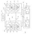
- FIG. 1depicts a high-level block diagram of a storage subsystem having redundant storage controllers each including a primary and secondary cache memory in accordance with an embodiment of the present invention.
- a host computer 110is coupled by a bus 120 to a first storage controller 130 and a second storage controller 135 (two controllers being shown by way of example only).
- Each of the storage controllers 130 and 135is coupled to each of a plurality of storage units S 1 -Sn in an array 140 by an I/O bus (or busses) 150 .
- Array 140is divided into logical array one (LA 1 ) and logical array two (LA 2 ).
- LA 1is associated with the first storage controller 130
- LA 2is associated with the second storage controller 135
- the interface bus 150 between the storage controllers 130 and 135 and disk array 140may be any of several industry standard interface busses including SCSI, IDE, EIDE, IPI, Fiber Channel, SSA, PCI, etc. Circuits (not shown) within the storage controllers 130 and 135 appropriate to the controlling bus 150 are well known to those of ordinary skill in the art.
- the interface bus 120 between the storage controllers 130 and 135 and the host computer 110may be any of several standard industry interface busses including SCSI, Ethernet (LAN), Token Ring (LAN), etc. Circuits (not shown) within the storage controllers 130 and 135 appropriate to controlling the bus 120 are well known to those of ordinary skill in the art.
- the first storage controller 130includes a CPU 131 , a program memory 132 (e.g. ROM/RAM devices for storing program instructions and variables for the operation of CPU 131 ), and the primary cache memory 133 for storing data and control information related to the data stored in the disk array 140 .
- the CPU 131 , the program memory 132 , and the primary cache memory 133are connected via the memory bus 130 - 1 to enable the CPU 131 to store and retrieve information in the memory devices.
- the first storage controller 130includes a secondary cache memory 134 also connected via the memory bus 130 - 1 .
- the second storage controller 135is identical to the first storage controller 130 and is comprised of a CPU 136 , a program memory 137 and a primary cache memory 138 , all interconnected via a memory bus 135 - 1 . As in the first storage controller 130 , the second storage controller 135 also includes a secondary cache memory 139 , which is also connected to the memory bus 135 - 1 . To permit each storage controller to communicate with the other, the storage controllers 130 and 135 are interconnected via the shared busses 160 .
- Each CPU 131 or 136 within each of the storage controller 130 or 135can manipulate the secondary cache memory 134 or 139 , respectively, of the other storage controller via the shared busses 160 .
- the primary cache memory 133 of the first storage controller 130is used by the CPU 131 via the bus 130 - 1 to buffer storage requests to or from the storage units S 1 -Sn.
- the secondary cache memory 134is reserved for use by the alternate second storage controller 135 via the shared busses 160 .
- the primary cache memory 138 in the second storage controller 135is used by the CPU 136 via the bus 135 - 1 to buffer storage requests to or from the storage units S 1 -Sn, as the secondary cache memory 139 is reserved for use by the alternate first storage controller 130 via the shared busses 160 .
- the storage controllers 130 and 135are interchangeable devices within the storage subsystem 100 to permit easy replacement, including hot swap, of a defective storage controller.
- One of ordinary skill in the artwill readily recognize that the block diagram of FIG. 1 is intended only as an exemplary design, which may embody the present invention. Many alternate controller and subsystem designs may embody the methods and associated apparatus and structures of the present invention.
- each of the storage controllers 130 and 135is assigned a subset of the storage units S 1 -Sn in the array 140 .
- Each of the storage units S 1 -Sncomprises non-overlapping groups of data blocks.
- the storage units S 1 -Snare logically grouped into two logical arrays LA 1 and LA 2 .
- the two storage controllers 130 and 135correspond one-to-one with the two logical arrays LA 1 , LA 2 and interface the logical arrays LA 1 , LA 2 with the host computer 110 . That is, each of the logical arrays LA 1 , LA 2 is controlled by a corresponding storage controller 130 , 135 .
- a storage controller 130 or 135fails, the other storage controller 135 , 130 assumes operational control of both of the logical arrays LA 1 , LA 2 .
- both of the storage controllers 130 , 135can be active simultaneously without concern that data access “collisions” will occur.
- each of the controllers 130 , 135monitors storage requests from the host computer 110 on essentially a continuous basis. Requests are directed to either the first logical array LA 1 (and thus the first storage controller 130 ) or the second logical array LA 2 (and thus the second storage controller 135 ). Each of the storage controllers 130 , 135 is active in parallel with the other to maintain cache information in its own primary cache memory as well as the secondary cache memory of the alternate storage controller. The first storage controller 130 maintains cache information related to management of LA 1 in its primary cache memory 133 and in the secondary cache memory 139 of the second storage controller 135 .
- the second storage controller 135maintains cache information related to management of LA 2 in its primary cache memory 138 and in the secondary cache memory 134 of the first storage controller 130 .
- each storage controllermaintains a complete snapshot of the present cache information as maintained by itself and the alternate storage controller. Since each controller 130 , 135 performs substantially the same functions, the functionality of the present invention is described below essentially with respect to only the first storage controller 130 for ease of understanding.
- the first storage controller 130determines whether a storage request has been received. If a storage request has been received, then the pending data block associated with the storage request is written to the primary cache memory 133 .
- Storage requests from the host computer 110can be either Write requests or Read requests. In the case of a Write request, the data block, associated with the storage request and recorded in the primary cache memory 133 , is representative of the write data (data from the host computer intended for a storage unit). If the storage request is a Read request, the data block associated with the storage request and recorded in the primary cache memory 133 is representative of the read data (request from the host computer for data from a storage unit). A Cache tag is generated for the recorded data block and recorded in the primary cache memory 133 of the first storage controller 135 .
- a Cache tagis a subset of the full address of the corresponding memory block.
- a compare match of an incoming address with one of the tags within the cache tag field in the primary cache memoryindicates a cache “hit.” Additionally, the cache tag is configured to indicate whether or not the recorded data block comprises dirty data.
- the cache tag and pending data block written to the primary cache memory 133are then immediately written (mirrored) to the secondary cache memory 139 of the second storage controller 135 .
- the SCSI write buffer commandmay be used to transfer the data to be mirrored from the controller containing the primary cache memory to the controller containing the secondary cache memory.
- an acknowledgeis sent to the host computer 110 only after the cache tag and pending data block have been completely written to the secondary cache memory 139 of the second storage controller 135 .
- storage requests from the host computer 110 to the primary cache memory 133 of the first storage controller 130are allowed to execute independently in parallel when the data accessed does not overlap with any data already in the primary cache memory. If new storage write requests from the host computer overlaps with data in process of being mirrored, this new write request from the host waits for the mirror operation to complete to ensure that the primary cache memory 133 of the first storage controller 130 does not obtain any dirty data that would not also be contained or mirrored in the secondary cache memory 139 of the second storage controller 135 .
- the storage subsystem of the present inventionprovides redundant storage of cache data while permitting operation of the storage subsystem in response to host computer storage requests. It should be noted that the operation of the primary cache memory 138 of the second storage controller 135 is not affected in any manner by the interaction between the primary cache memory 133 of the first storage controller 130 and the secondary cache memory 139 of the redundant second storage controller 135 . Thus the ability of the primary cache memory 138 of the redundant second storage controller 135 to respond to storage requests during interaction between its secondary cache memory 139 and the primary cache memory 133 of the first storage controller 130 is in no way negatively affected or delayed.
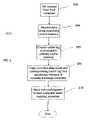
- FIG. 2depicts a flow diagram of the above-described method of the present invention.
- the method 200is entered at step 202 wherein a storage controller determines whether a storage request has been received from the host computer.
- the pending data block associated with the storage requestis written to the primary cache memory of the storage controller.
- a cache tag identifying the data block(including whether the data block is dirty data) is created for the recorded data block and recorded in the primary cache of the storage controller that received the storage request from the host computer.
- the recorded data block and corresponding cache tagare mirrored and copied to the secondary cache memory of an alternate (redundant) storage controller.
- step 210upon completion of the mirroring process, (e.g., the data block and corresponding cache tag are completely copied into the secondary cache memory of the redundant storage controller) an acknowledgement is transmitted to the host computer.
- the method 200is performed in parallel by each storage controller. The method 200 ends after step 210 is completed.
- a cachemay be flushed periodically or when certain predefined conditions are met. Flushing techniques and schedules are well known in the art, and it would be appreciated by one skilled in the art, that the subject invention can advantageously employ a plurality of flushing techniques as long as the cache tags of a secondary cache memory of a redundant storage controller are “zeroed” (cleared) upon a flush of the dirty data in a primary cache memory of a first storage controller.
- the cache tags in the primary cache memory 133 corresponding to the flushed data blocksare reset to indicate that those data blocks are no longer dirty, and the mirrored cache tags for the corresponding data blocks in the secondary cache memory 139 of the second storage controller 135 are “zeroed”.
- the mirrored cache tags for the corresponding data blocks in the secondary cache memory 139 of the second storage controller 135are “zeroed”.
- the read datawould remain on both the primary cache memory 133 of the first storage controller 130 and the secondary cache memory 139 of the redundant second storage controller 135 while any flushed dirty data previously in the primary cache memory of the first storage controller is deleted from the secondary cache memory of the redundant second storage controller.
- the storage unitsupon a failure of the primary cache memory 133 of the first storage controller 130 , the storage units will not need to be searched upon a subsequent storage request from the host computer 110 for read data blocks that were previously recorded in the primary cache memory 133 of the first storage controller 130 , because the read data blocks remain in the secondary cache memory 139 of the redundant second storage controller 135 .
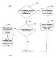
- FIG. 3depicts a flow diagram of a conventional cache memory flush process 300 that can be employed in the storage subsystem of FIG. 1 . Accordingly, as shown in steps 302 , 304 , and 306 , if a cache flush is scheduled or if predetermined conditions for a cache flush are met (step 302 ), the cache memory is flushed as shown in step 304 . That is, dirty data in a primary cache memory of a storage controller is written to the persistent memory (storage units).
- the corresponding cache tags in the primary cache memory of the storage controller responding to the storage requestare reset to indicate that the flushed data is no longer dirty data, and the corresponding cache tags in a secondary cache memory of a redundant storage controller are zeroed (step 306 ).
- This instructionmay be communicated to the secondary cache memory of the redundant storage controller via a shared bus between the storage controllers, such as shared busses 160 between storage controllers 130 , 135 in the storage subsystem 100 of FIG. 1 . This process is implemented to ensure that the secondary cache memory of the redundant storage controller will not include stale data (data flushed from the primary storage controller to the storage units).
- steps 308 , 310 , and 312if the primary cache memory of a storage controller is full of dirty data blocks when an storage request is sent to the storage controller (Step 308 ), dirty data blocks in the primary cache memory of the storage controller that received the storage request are flushed by a replacement algorithm to accommodate the storage request.
- the corresponding cache tags of the flushed data in the primary storage controllerare reset to indicate that the data is no longer dirty data (Step 310 ).
- the mirrored cache tags in the secondary cache memory of the redundant storage controller corresponding to the flushed dirty dataare zeroed (Step 312 ).
- each controller 130 , 135performs substantially the same functions, the functionality of the present invention with respect to a failure is described below with respect to a failure of the first storage controller 130 and the functionality of the second storage controller 135 in response to the failure.
- the failureis detected by the redundant second storage controller 135 .
- the occurrence of a non-correctable ECC error in the primary cache memorycan be used to detect a failure in the first storage controller 130 .
- the host computerUpon detection of a failure of the first storage controller 130 , the host computer addresses any storage requests intended for LA 1 , originally processed by the first storage controller 130 , to the secondary cache memory 139 of the redundant second storage controller 135 utilizing bus 120 , processor 136 , and memory bus 135 - 1 . Accordingly and as mentioned above, upon detection of the failure of the first storage controller 130 , the second storage controller 135 assumes operational control of both logical arrays LA 1 , LA 2 . At this point, the storage subsystem operates as a system with one storage controller 135 and two cache memories 138 , 139 , each of the cache memories 138 , 139 corresponding to an individual logical array LA 2 , LA 1 , respectively. That is, the secondary cache memory 139 of the second controller 135 , now performs the function of the failed primary cache memory 133 of the first storage controller 130 .
- the secondary cache memory 139 of the remaining storage controller 135is flushed as soon as possible after the detection of the failure of the primary cache memory 133 of the first storage controller 130 , in order to flush the dirty data that was copied from primary cache memory 133 of the first storage controller 130 to the appropriate storage unit(s). Additionally, the primary cache memory 138 of the remaining storage controller 135 is flushed at the same time as the secondary cache memory 139 , to take full advantage of the flushing time required, thus minimizing processing time.
- the remaining cache memoryis configured to operate as the cache memory for all of the storage requests from the host computer 110 intended for both LA 1 and LA 2 .
- the secondary cache memory 139 of the remaining storage controller 135could subsequently be configured to operate within various embodiments. Examples of these alternative embodiments for the functionality of the secondary memory 139 of the second storage controller 135 are disclosed and claimed in commonly-assigned U.S. patent application Ser. No. 10/430,487, filed May 5, 2003, issued as U.S. Pat. No. 7,162,587), entitled “METHOD AND APPARATUS FOR RECOVERING REDUNDANT CACHE DATA OF A FAILED CONTROLLER AND REESTABLISHING REDUNDANCY”, which is herein incorporated by reference in its entirety.
- a structured list of cache tagsis created identifying the data blocks in the secondary cache memory 139 for minimizing a delay associated with processing a storage request from the host computer 110 .
- the secondary cache memory 139 of the storage controller 135can be configured to function as a redundant cache memory for the primary cache memory 138 .
- the storage controller 135can also be configured to operate in conjunction with another available storage controller to again establish a redundant cache storage subsystem as the storage subsystem 100 of FIG.1
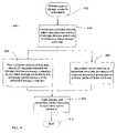
- FIG. 4depicts a flow diagram of a response of the present invention to a failure detection of a storage controller.
- the method 400is entered at step 402 wherein a failure occurs in a primary cache of a storage controller.
- a redundant controllerdetects the failure and assumes control of the storage devices previously controlled by the failed storage controller.
- the secondary cache memory of the redundant second storage controllercontaining mirrored copies of the data blocks and cache tags of the primary cache memory of the failed storage controller, is configured to process any storage requests from the host computer intended for the failed storage controller, which was configured to control specific storage devices.
- the redundant second storage controller 135assumes control of both LA 1 and LA 2 and any storage requests intended for LA 1 are directed to the secondary cache memory 139 of the redundant second storage controller 135 .
- step 408performed substantially in parallel with step 406 , the host computer detects the failure of the first storage controller and directs any storage requests intended for the storage units previously controlled by the failed storage controller, to the secondary cache memory of the redundant storage controller.
- the primary cache memory and the secondary cache memory of the remaining (not failed) second storage controllerare flushed (applicable flushing techniques were described above).
- the primary cache memory and the secondary cache memory of the second storage controllerare depicted as being flushed at step 410 , it will be appreciated by one skilled in the art that the cache memories can be advantageously flushed at different times and utilizing various methods.
- the cache memories of the redundant controllershould be flushed as soon as possible after the failure of the first storage controller in order to flush the dirty data in the secondary cache memory of the second storage controller previously contained in the primary cache memory of the failed storage controller and to take full advantage of the required flushing processing time.
- the method 400ends at step 412 .
Landscapes
- Engineering & Computer Science (AREA)
- Theoretical Computer Science (AREA)
- Quality & Reliability (AREA)
- Physics & Mathematics (AREA)
- General Engineering & Computer Science (AREA)
- General Physics & Mathematics (AREA)
- Memory System Of A Hierarchy Structure (AREA)
Abstract
Description
Claims (11)
Priority Applications (1)
| Application Number | Priority Date | Filing Date | Title |
|---|---|---|---|
| US10/434,489US7293196B2 (en) | 2002-05-08 | 2003-05-07 | Method, apparatus, and system for preserving cache data of redundant storage controllers |
Applications Claiming Priority (3)
| Application Number | Priority Date | Filing Date | Title |
|---|---|---|---|
| US37900102P | 2002-05-08 | 2002-05-08 | |
| US10/430,487US7162587B2 (en) | 2002-05-08 | 2003-05-05 | Method and apparatus for recovering redundant cache data of a failed controller and reestablishing redundancy |
| US10/434,489US7293196B2 (en) | 2002-05-08 | 2003-05-07 | Method, apparatus, and system for preserving cache data of redundant storage controllers |
Related Parent Applications (1)
| Application Number | Title | Priority Date | Filing Date |
|---|---|---|---|
| US10/430,487Continuation-In-PartUS7162587B2 (en) | 2002-05-08 | 2003-05-05 | Method and apparatus for recovering redundant cache data of a failed controller and reestablishing redundancy |
Publications (2)
| Publication Number | Publication Date |
|---|---|
| US20030212864A1 US20030212864A1 (en) | 2003-11-13 |
| US7293196B2true US7293196B2 (en) | 2007-11-06 |
Family
ID=29406883
Family Applications (1)
| Application Number | Title | Priority Date | Filing Date |
|---|---|---|---|
| US10/434,489Expired - LifetimeUS7293196B2 (en) | 2002-05-08 | 2003-05-07 | Method, apparatus, and system for preserving cache data of redundant storage controllers |
Country Status (1)
| Country | Link |
|---|---|
| US (1) | US7293196B2 (en) |
Cited By (26)
| Publication number | Priority date | Publication date | Assignee | Title |
|---|---|---|---|---|
| US20050246388A1 (en)* | 2003-07-02 | 2005-11-03 | Satoshi Yamatake | Image database system |
| US20060107004A1 (en)* | 2004-11-16 | 2006-05-18 | Benhase Michael T | Recovery from failure in data storage systems |
| US20080040552A1 (en)* | 2006-08-10 | 2008-02-14 | Fujitsu Limited | Duplex system and processor switching method |
| US20080155307A1 (en)* | 2006-09-28 | 2008-06-26 | Emc Corporation | Responding to a storage processor failure with continued write caching |
| US20080222359A1 (en)* | 2007-03-06 | 2008-09-11 | Hitachi, Ltd. | Storage system and data management method |
| US20100218022A1 (en)* | 2009-02-23 | 2010-08-26 | Nec Electronics Corporation | Processor system and operation mode switching method for processor system |
| US7849352B2 (en) | 2003-08-14 | 2010-12-07 | Compellent Technologies | Virtual disk drive system and method |
| US20110022801A1 (en)* | 2007-12-06 | 2011-01-27 | David Flynn | Apparatus, system, and method for redundant write caching |
| US7886111B2 (en) | 2006-05-24 | 2011-02-08 | Compellent Technologies | System and method for raid management, reallocation, and restriping |
| US20110231369A1 (en)* | 2009-10-20 | 2011-09-22 | Hitachi, Ltd. | Storage controller for mirroring data written to cache memory area |
| US20120166699A1 (en)* | 2010-12-22 | 2012-06-28 | Panakaj Kumar | Method and apparatus to provide a high availability solid state drive |
| US8468292B2 (en) | 2009-07-13 | 2013-06-18 | Compellent Technologies | Solid state drive data storage system and method |
| US8627012B1 (en) | 2011-12-30 | 2014-01-07 | Emc Corporation | System and method for improving cache performance |
| US8745330B2 (en) | 2011-08-12 | 2014-06-03 | International Business Machines Corporation | Technique for improving replication persistance in a caching applicance structure |
| US8930947B1 (en) | 2011-12-30 | 2015-01-06 | Emc Corporation | System and method for live migration of a virtual machine with dedicated cache |
| US20150067231A1 (en)* | 2013-08-28 | 2015-03-05 | Compellent Technologies | On-Demand Snapshot and Prune in a Data Storage System |
| US9009416B1 (en) | 2011-12-30 | 2015-04-14 | Emc Corporation | System and method for managing cache system content directories |
| US9053033B1 (en) | 2011-12-30 | 2015-06-09 | Emc Corporation | System and method for cache content sharing |
| US9104529B1 (en)* | 2011-12-30 | 2015-08-11 | Emc Corporation | System and method for copying a cache system |
| US9146851B2 (en) | 2012-03-26 | 2015-09-29 | Compellent Technologies | Single-level cell and multi-level cell hybrid solid state drive |
| US9158578B1 (en) | 2011-12-30 | 2015-10-13 | Emc Corporation | System and method for migrating virtual machines |
| US9235524B1 (en) | 2011-12-30 | 2016-01-12 | Emc Corporation | System and method for improving cache performance |
| US9489150B2 (en) | 2003-08-14 | 2016-11-08 | Dell International L.L.C. | System and method for transferring data between different raid data storage types for current data and replay data |
| US9762772B1 (en) | 2016-07-12 | 2017-09-12 | Ricoh Company, Ltd. | Color hash table reuse for print job processing |
| US9992381B2 (en) | 2016-02-24 | 2018-06-05 | Ricoh Company, Ltd. | Color hash table reuse for print job processing |
| US11573909B2 (en) | 2006-12-06 | 2023-02-07 | Unification Technologies Llc | Apparatus, system, and method for managing commands of solid-state storage using bank interleave |
Families Citing this family (21)
| Publication number | Priority date | Publication date | Assignee | Title |
|---|---|---|---|---|
| US6883065B1 (en) | 2001-11-15 | 2005-04-19 | Xiotech Corporation | System and method for a redundant communication channel via storage area network back-end |
| US7380163B2 (en)* | 2003-04-23 | 2008-05-27 | Dot Hill Systems Corporation | Apparatus and method for deterministically performing active-active failover of redundant servers in response to a heartbeat link failure |
| US7827353B2 (en)* | 2003-07-15 | 2010-11-02 | International Business Machines Corporation | Self healing memory |
| JP4437650B2 (en)* | 2003-08-25 | 2010-03-24 | 株式会社日立製作所 | Storage system |
| WO2005026912A2 (en)* | 2003-09-10 | 2005-03-24 | Hyperdata Technologies, Inc. | Internet protocol optimizer |
| JP4477906B2 (en)* | 2004-03-12 | 2010-06-09 | 株式会社日立製作所 | Storage system |
| TWI344602B (en)* | 2005-01-13 | 2011-07-01 | Infortrend Technology Inc | Redundant storage virtualization computer system |
| US7337350B2 (en)* | 2005-02-09 | 2008-02-26 | Hitachi, Ltd. | Clustered storage system with external storage systems |
| JP4430093B2 (en)* | 2007-08-29 | 2010-03-10 | 富士通株式会社 | Storage control device and firmware update method |
| EP2323047B1 (en)* | 2009-10-09 | 2020-02-19 | Software AG | Primary database system, replication database system and method for replicating data of a primary database system |
| US9507534B2 (en)* | 2011-12-30 | 2016-11-29 | Intel Corporation | Home agent multi-level NVM memory architecture |
| US9135119B1 (en)* | 2012-09-28 | 2015-09-15 | Emc Corporation | System and method for data management |
| US20150019822A1 (en)* | 2013-07-11 | 2015-01-15 | Lsi Corporation | System for Maintaining Dirty Cache Coherency Across Reboot of a Node |
| US9355034B2 (en)* | 2013-12-31 | 2016-05-31 | Samsung Electronics Co., Ltd. | Removal and optimization of coherence acknowledgement responses in an interconnect |
| US10630802B2 (en)* | 2015-12-07 | 2020-04-21 | International Business Machines Corporation | Read caching in PPRC environments |
| KR102362239B1 (en)* | 2015-12-30 | 2022-02-14 | 삼성전자주식회사 | Memory system including dram cache and cache management method thereof |
| US11175831B2 (en)* | 2016-10-14 | 2021-11-16 | Netapp, Inc. | Read and write load sharing in a storage array via partitioned ownership of data blocks |
| US10216598B2 (en)* | 2017-07-11 | 2019-02-26 | Stratus Technologies Bermuda Ltd. | Method for dirty-page tracking and full memory mirroring redundancy in a fault-tolerant server |
| US11287986B2 (en)* | 2018-12-31 | 2022-03-29 | Micron Technology, Inc. | Reset interception to avoid data loss in storage device resets |
| US11354208B2 (en)* | 2019-09-11 | 2022-06-07 | International Business Machines Corporation | Adjustment of safe data commit scan based on operational verification of non-volatile memory |
| CN115237667A (en) | 2021-04-23 | 2022-10-25 | 伊姆西Ip控股有限责任公司 | Method, electronic device and computer program product for storage management |
Citations (10)
| Publication number | Priority date | Publication date | Assignee | Title |
|---|---|---|---|---|
| US5699510A (en)* | 1994-12-15 | 1997-12-16 | Hewlett-Packard Company | Failure detection system for a mirrored memory dual controller disk storage system |
| US5761705A (en)* | 1996-04-04 | 1998-06-02 | Symbios, Inc. | Methods and structure for maintaining cache consistency in a RAID controller having redundant caches |
| US5974506A (en)* | 1996-06-28 | 1999-10-26 | Digital Equipment Corporation | Enabling mirror, nonmirror and partial mirror cache modes in a dual cache system |
| US20010020282A1 (en)* | 1995-10-30 | 2001-09-06 | Akira Murotani | External storage |
| US6330642B1 (en)* | 2000-06-29 | 2001-12-11 | Bull Hn Informatin Systems Inc. | Three interconnected raid disk controller data processing system architecture |
| US6438647B1 (en)* | 2000-06-23 | 2002-08-20 | International Business Machines Corporation | Method and apparatus for providing battery-backed immediate write back cache for an array of disk drives in a computer system |
| US6571324B1 (en)* | 1997-06-26 | 2003-05-27 | Hewlett-Packard Development Company, L.P. | Warmswap of failed memory modules and data reconstruction in a mirrored writeback cache system |
| US6681339B2 (en)* | 2001-01-16 | 2004-01-20 | International Business Machines Corporation | System and method for efficient failover/failback techniques for fault-tolerant data storage system |
| US20040153727A1 (en)* | 2002-05-08 | 2004-08-05 | Hicken Michael S. | Method and apparatus for recovering redundant cache data of a failed controller and reestablishing redundancy |
| US6801954B1 (en)* | 2000-02-25 | 2004-10-05 | Hewlett-Packard Development Company, L.P. | Method and apparatus to concurrently operate on multiple data movement transactions in a disk array subsystem |
- 2003
- 2003-05-07USUS10/434,489patent/US7293196B2/ennot_activeExpired - Lifetime
Patent Citations (10)
| Publication number | Priority date | Publication date | Assignee | Title |
|---|---|---|---|---|
| US5699510A (en)* | 1994-12-15 | 1997-12-16 | Hewlett-Packard Company | Failure detection system for a mirrored memory dual controller disk storage system |
| US20010020282A1 (en)* | 1995-10-30 | 2001-09-06 | Akira Murotani | External storage |
| US5761705A (en)* | 1996-04-04 | 1998-06-02 | Symbios, Inc. | Methods and structure for maintaining cache consistency in a RAID controller having redundant caches |
| US5974506A (en)* | 1996-06-28 | 1999-10-26 | Digital Equipment Corporation | Enabling mirror, nonmirror and partial mirror cache modes in a dual cache system |
| US6571324B1 (en)* | 1997-06-26 | 2003-05-27 | Hewlett-Packard Development Company, L.P. | Warmswap of failed memory modules and data reconstruction in a mirrored writeback cache system |
| US6801954B1 (en)* | 2000-02-25 | 2004-10-05 | Hewlett-Packard Development Company, L.P. | Method and apparatus to concurrently operate on multiple data movement transactions in a disk array subsystem |
| US6438647B1 (en)* | 2000-06-23 | 2002-08-20 | International Business Machines Corporation | Method and apparatus for providing battery-backed immediate write back cache for an array of disk drives in a computer system |
| US6330642B1 (en)* | 2000-06-29 | 2001-12-11 | Bull Hn Informatin Systems Inc. | Three interconnected raid disk controller data processing system architecture |
| US6681339B2 (en)* | 2001-01-16 | 2004-01-20 | International Business Machines Corporation | System and method for efficient failover/failback techniques for fault-tolerant data storage system |
| US20040153727A1 (en)* | 2002-05-08 | 2004-08-05 | Hicken Michael S. | Method and apparatus for recovering redundant cache data of a failed controller and reestablishing redundancy |
Cited By (56)
| Publication number | Priority date | Publication date | Assignee | Title |
|---|---|---|---|---|
| US20050246388A1 (en)* | 2003-07-02 | 2005-11-03 | Satoshi Yamatake | Image database system |
| US7945810B2 (en) | 2003-08-14 | 2011-05-17 | Compellent Technologies | Virtual disk drive system and method |
| US7962778B2 (en) | 2003-08-14 | 2011-06-14 | Compellent Technologies | Virtual disk drive system and method |
| US8555108B2 (en) | 2003-08-14 | 2013-10-08 | Compellent Technologies | Virtual disk drive system and method |
| US9436390B2 (en) | 2003-08-14 | 2016-09-06 | Dell International L.L.C. | Virtual disk drive system and method |
| US7941695B2 (en) | 2003-08-14 | 2011-05-10 | Compellent Technolgoies | Virtual disk drive system and method |
| US9047216B2 (en) | 2003-08-14 | 2015-06-02 | Compellent Technologies | Virtual disk drive system and method |
| US8560880B2 (en) | 2003-08-14 | 2013-10-15 | Compellent Technologies | Virtual disk drive system and method |
| US8020036B2 (en) | 2003-08-14 | 2011-09-13 | Compellent Technologies | Virtual disk drive system and method |
| US8473776B2 (en) | 2003-08-14 | 2013-06-25 | Compellent Technologies | Virtual disk drive system and method |
| US8321721B2 (en) | 2003-08-14 | 2012-11-27 | Compellent Technologies | Virtual disk drive system and method |
| US10067712B2 (en) | 2003-08-14 | 2018-09-04 | Dell International L.L.C. | Virtual disk drive system and method |
| US9021295B2 (en) | 2003-08-14 | 2015-04-28 | Compellent Technologies | Virtual disk drive system and method |
| US7849352B2 (en) | 2003-08-14 | 2010-12-07 | Compellent Technologies | Virtual disk drive system and method |
| US9489150B2 (en) | 2003-08-14 | 2016-11-08 | Dell International L.L.C. | System and method for transferring data between different raid data storage types for current data and replay data |
| US7568121B2 (en)* | 2004-11-16 | 2009-07-28 | International Business Machines Corporation | Recovery from failure in data storage systems |
| US20060107004A1 (en)* | 2004-11-16 | 2006-05-18 | Benhase Michael T | Recovery from failure in data storage systems |
| US10296237B2 (en) | 2006-05-24 | 2019-05-21 | Dell International L.L.C. | System and method for raid management, reallocation, and restripping |
| US9244625B2 (en) | 2006-05-24 | 2016-01-26 | Compellent Technologies | System and method for raid management, reallocation, and restriping |
| US8230193B2 (en) | 2006-05-24 | 2012-07-24 | Compellent Technologies | System and method for raid management, reallocation, and restriping |
| US7886111B2 (en) | 2006-05-24 | 2011-02-08 | Compellent Technologies | System and method for raid management, reallocation, and restriping |
| US20080040552A1 (en)* | 2006-08-10 | 2008-02-14 | Fujitsu Limited | Duplex system and processor switching method |
| US7849350B2 (en)* | 2006-09-28 | 2010-12-07 | Emc Corporation | Responding to a storage processor failure with continued write caching |
| US20080155307A1 (en)* | 2006-09-28 | 2008-06-26 | Emc Corporation | Responding to a storage processor failure with continued write caching |
| US11960412B2 (en) | 2006-12-06 | 2024-04-16 | Unification Technologies Llc | Systems and methods for identifying storage resources that are not in use |
| US11573909B2 (en) | 2006-12-06 | 2023-02-07 | Unification Technologies Llc | Apparatus, system, and method for managing commands of solid-state storage using bank interleave |
| US11640359B2 (en) | 2006-12-06 | 2023-05-02 | Unification Technologies Llc | Systems and methods for identifying storage resources that are not in use |
| US11847066B2 (en) | 2006-12-06 | 2023-12-19 | Unification Technologies Llc | Apparatus, system, and method for managing commands of solid-state storage using bank interleave |
| US8200897B2 (en) | 2007-03-06 | 2012-06-12 | Hitachi, Ltd. | Storage system and data management method |
| US8006036B2 (en)* | 2007-03-06 | 2011-08-23 | Hitachi, Ltd. | Storage system and data management method |
| US20080222359A1 (en)* | 2007-03-06 | 2008-09-11 | Hitachi, Ltd. | Storage system and data management method |
| US8706968B2 (en)* | 2007-12-06 | 2014-04-22 | Fusion-Io, Inc. | Apparatus, system, and method for redundant write caching |
| US20110022801A1 (en)* | 2007-12-06 | 2011-01-27 | David Flynn | Apparatus, system, and method for redundant write caching |
| US8458516B2 (en)* | 2009-02-23 | 2013-06-04 | Renesas Electronics Corporation | Processor system and operation mode switching method for processor system |
| US20100218022A1 (en)* | 2009-02-23 | 2010-08-26 | Nec Electronics Corporation | Processor system and operation mode switching method for processor system |
| US8468292B2 (en) | 2009-07-13 | 2013-06-18 | Compellent Technologies | Solid state drive data storage system and method |
| US8819334B2 (en) | 2009-07-13 | 2014-08-26 | Compellent Technologies | Solid state drive data storage system and method |
| US8296516B2 (en)* | 2009-10-20 | 2012-10-23 | Hitachi, Ltd. | Storage controller for mirroring data written to cache memory area |
| US20110231369A1 (en)* | 2009-10-20 | 2011-09-22 | Hitachi, Ltd. | Storage controller for mirroring data written to cache memory area |
| US8589723B2 (en)* | 2010-12-22 | 2013-11-19 | Intel Corporation | Method and apparatus to provide a high availability solid state drive |
| US20120166699A1 (en)* | 2010-12-22 | 2012-06-28 | Panakaj Kumar | Method and apparatus to provide a high availability solid state drive |
| US8745331B2 (en) | 2011-08-12 | 2014-06-03 | International Business Machines Corporation | Technique for improving replication persistance in a caching applicance structure |
| US8745330B2 (en) | 2011-08-12 | 2014-06-03 | International Business Machines Corporation | Technique for improving replication persistance in a caching applicance structure |
| US9053033B1 (en) | 2011-12-30 | 2015-06-09 | Emc Corporation | System and method for cache content sharing |
| US9009416B1 (en) | 2011-12-30 | 2015-04-14 | Emc Corporation | System and method for managing cache system content directories |
| US8930947B1 (en) | 2011-12-30 | 2015-01-06 | Emc Corporation | System and method for live migration of a virtual machine with dedicated cache |
| US9104529B1 (en)* | 2011-12-30 | 2015-08-11 | Emc Corporation | System and method for copying a cache system |
| US9235524B1 (en) | 2011-12-30 | 2016-01-12 | Emc Corporation | System and method for improving cache performance |
| US8627012B1 (en) | 2011-12-30 | 2014-01-07 | Emc Corporation | System and method for improving cache performance |
| US9158578B1 (en) | 2011-12-30 | 2015-10-13 | Emc Corporation | System and method for migrating virtual machines |
| US9146851B2 (en) | 2012-03-26 | 2015-09-29 | Compellent Technologies | Single-level cell and multi-level cell hybrid solid state drive |
| US9519439B2 (en)* | 2013-08-28 | 2016-12-13 | Dell International L.L.C. | On-demand snapshot and prune in a data storage system |
| US10019183B2 (en) | 2013-08-28 | 2018-07-10 | Dell International L.L.C. | On-demand snapshot and prune in a data storage system |
| US20150067231A1 (en)* | 2013-08-28 | 2015-03-05 | Compellent Technologies | On-Demand Snapshot and Prune in a Data Storage System |
| US9992381B2 (en) | 2016-02-24 | 2018-06-05 | Ricoh Company, Ltd. | Color hash table reuse for print job processing |
| US9762772B1 (en) | 2016-07-12 | 2017-09-12 | Ricoh Company, Ltd. | Color hash table reuse for print job processing |
Also Published As
| Publication number | Publication date |
|---|---|
| US20030212864A1 (en) | 2003-11-13 |
Similar Documents
| Publication | Publication Date | Title |
|---|---|---|
| US7293196B2 (en) | Method, apparatus, and system for preserving cache data of redundant storage controllers | |
| US7162587B2 (en) | Method and apparatus for recovering redundant cache data of a failed controller and reestablishing redundancy | |
| US5933653A (en) | Method and apparatus for mirroring data in a remote data storage system | |
| JP4041473B2 (en) | Autonomous power loss recovery for multi-cluster storage subsystems | |
| US5640530A (en) | Use of configuration registers to control access to multiple caches and nonvolatile stores | |
| US7669008B2 (en) | Destage management of redundant data copies | |
| US6513097B1 (en) | Method and system for maintaining information about modified data in cache in a storage system for use during a system failure | |
| US7600152B2 (en) | Configuring cache memory from a storage controller | |
| US5586291A (en) | Disk controller with volatile and non-volatile cache memories | |
| US5548711A (en) | Method and apparatus for fault tolerant fast writes through buffer dumping | |
| US7996609B2 (en) | System and method of dynamic allocation of non-volatile memory | |
| US7171516B2 (en) | Increasing through-put of a storage controller by autonomically adjusting host delay | |
| US6006342A (en) | Failover and failback system for a direct access storage device | |
| US5724501A (en) | Quick recovery of write cache in a fault tolerant I/O system | |
| US7185222B2 (en) | Apparatus, system, and method for maintaining data in a storage array | |
| KR100267029B1 (en) | Memory update history storing apparatus and method | |
| JP5353887B2 (en) | Disk array device control unit, data transfer device, and power recovery processing method | |
| US6604171B1 (en) | Managing a cache memory | |
| US9940201B2 (en) | Disk array having mirror configuration and rebuilding method therefor | |
| US6591335B1 (en) | Fault tolerant dual cache system | |
| US7266653B2 (en) | Remote data mirroring with acknowledgment upon writing copied data to volatile cache memory | |
| US20070028045A1 (en) | Method for improving writing data efficiency and storage subsystem and system implementing the same | |
| JPH06222988A (en) | Storage-device controller and data preservation method | |
| JPH1185408A (en) | Storage controller | |
| JP2005301419A (en) | Disk array device and data processing method thereof |
Legal Events
| Date | Code | Title | Description |
|---|---|---|---|
| AS | Assignment | Owner name:XIOTECH CORPORATION, MINNESOTA Free format text:ASSIGNMENT OF ASSIGNORS INTEREST;ASSIGNORS:HICKEN, MICHAEL S.;SNEAD, JAMES N.;REEL/FRAME:014061/0949 Effective date:20030506 | |
| STCF | Information on status: patent grant | Free format text:PATENTED CASE | |
| AS | Assignment | Owner name:HORIZON TECHNOLOGY FUNDING COMPANY V LLC, CONNECTI Free format text:SECURITY AGREEMENT;ASSIGNOR:XIOTECH CORPORATION;REEL/FRAME:020061/0847 Effective date:20071102 Owner name:SILICON VALLEY BANK, CALIFORNIA Free format text:SECURITY AGREEMENT;ASSIGNOR:XIOTECH CORPORATION;REEL/FRAME:020061/0847 Effective date:20071102 Owner name:HORIZON TECHNOLOGY FUNDING COMPANY V LLC,CONNECTIC Free format text:SECURITY AGREEMENT;ASSIGNOR:XIOTECH CORPORATION;REEL/FRAME:020061/0847 Effective date:20071102 Owner name:SILICON VALLEY BANK,CALIFORNIA Free format text:SECURITY AGREEMENT;ASSIGNOR:XIOTECH CORPORATION;REEL/FRAME:020061/0847 Effective date:20071102 | |
| CC | Certificate of correction | ||
| FPAY | Fee payment | Year of fee payment:4 | |
| FEPP | Fee payment procedure | Free format text:PAT HOLDER CLAIMS SMALL ENTITY STATUS, ENTITY STATUS SET TO SMALL (ORIGINAL EVENT CODE: LTOS); ENTITY STATUS OF PATENT OWNER: SMALL ENTITY | |
| FEPP | Fee payment procedure | Free format text:PAYER NUMBER DE-ASSIGNED (ORIGINAL EVENT CODE: RMPN); ENTITY STATUS OF PATENT OWNER: SMALL ENTITY Free format text:PAYOR NUMBER ASSIGNED (ORIGINAL EVENT CODE: ASPN); ENTITY STATUS OF PATENT OWNER: SMALL ENTITY | |
| FPAY | Fee payment | Year of fee payment:8 | |
| AS | Assignment | Owner name:XIOTECH CORPORATION, COLORADO Free format text:RELEASE BY SECURED PARTY;ASSIGNOR:HORIZON TECHNOLOGY FUNDING COMPANY V LLC;REEL/FRAME:044883/0095 Effective date:20171214 Owner name:XIOTECH CORPORATION, COLORADO Free format text:RELEASE BY SECURED PARTY;ASSIGNOR:SILICON VALLEY BANK;REEL/FRAME:044891/0322 Effective date:20171214 | |
| FEPP | Fee payment procedure | Free format text:MAINTENANCE FEE REMINDER MAILED (ORIGINAL EVENT CODE: REM.); ENTITY STATUS OF PATENT OWNER: SMALL ENTITY | |
| FEPP | Fee payment procedure | Free format text:11.5 YR SURCHARGE- LATE PMT W/IN 6 MO, SMALL ENTITY (ORIGINAL EVENT CODE: M2556); ENTITY STATUS OF PATENT OWNER: SMALL ENTITY | |
| MAFP | Maintenance fee payment | Free format text:PAYMENT OF MAINTENANCE FEE, 12TH YR, SMALL ENTITY (ORIGINAL EVENT CODE: M2553); ENTITY STATUS OF PATENT OWNER: SMALL ENTITY Year of fee payment:12 |