US7292137B2 - Energy efficient passive entry system - Google Patents
Energy efficient passive entry systemDownload PDFInfo
- Publication number
- US7292137B2 US7292137B2US11/129,159US12915905AUS7292137B2US 7292137 B2US7292137 B2US 7292137B2US 12915905 AUS12915905 AUS 12915905AUS 7292137 B2US7292137 B2US 7292137B2
- Authority
- US
- United States
- Prior art keywords
- communication device
- portable communication
- vehicle
- signal
- response
- Prior art date
- Legal status (The legal status is an assumption and is not a legal conclusion. Google has not performed a legal analysis and makes no representation as to the accuracy of the status listed.)
- Active, expires
Links
- 238000004891communicationMethods0.000claimsabstractdescription227
- 230000004044responseEffects0.000claimsabstractdescription93
- 238000000034methodMethods0.000claimsdescription12
- 230000004913activationEffects0.000claimsdescription3
- 230000003213activating effectEffects0.000description6
- 238000010586diagramMethods0.000description4
- 230000008901benefitEffects0.000description3
- 238000012544monitoring processMethods0.000description3
- 230000009466transformationEffects0.000description3
- 230000007246mechanismEffects0.000description2
- 230000004888barrier functionEffects0.000description1
- 230000005540biological transmissionEffects0.000description1
- 230000000881depressing effectEffects0.000description1
- 230000000977initiatory effectEffects0.000description1
- 230000004807localizationEffects0.000description1
- 238000012986modificationMethods0.000description1
- 230000004048modificationEffects0.000description1
- 230000001105regulatory effectEffects0.000description1
- 238000011160researchMethods0.000description1
- 230000035945sensitivityEffects0.000description1
- 238000010200validation analysisMethods0.000description1
Images


Classifications
- G—PHYSICS
- G07—CHECKING-DEVICES
- G07C—TIME OR ATTENDANCE REGISTERS; REGISTERING OR INDICATING THE WORKING OF MACHINES; GENERATING RANDOM NUMBERS; VOTING OR LOTTERY APPARATUS; ARRANGEMENTS, SYSTEMS OR APPARATUS FOR CHECKING NOT PROVIDED FOR ELSEWHERE
- G07C9/00—Individual registration on entry or exit
- G07C9/00174—Electronically operated locks; Circuits therefor; Nonmechanical keys therefor, e.g. passive or active electrical keys or other data carriers without mechanical keys
- G07C9/00309—Electronically operated locks; Circuits therefor; Nonmechanical keys therefor, e.g. passive or active electrical keys or other data carriers without mechanical keys operated with bidirectional data transmission between data carrier and locks
- B—PERFORMING OPERATIONS; TRANSPORTING
- B60—VEHICLES IN GENERAL
- B60R—VEHICLES, VEHICLE FITTINGS, OR VEHICLE PARTS, NOT OTHERWISE PROVIDED FOR
- B60R25/00—Fittings or systems for preventing or indicating unauthorised use or theft of vehicles
- B60R25/20—Means to switch the anti-theft system on or off
- B60R25/24—Means to switch the anti-theft system on or off using electronic identifiers containing a code not memorised by the user
- G—PHYSICS
- G07—CHECKING-DEVICES
- G07C—TIME OR ATTENDANCE REGISTERS; REGISTERING OR INDICATING THE WORKING OF MACHINES; GENERATING RANDOM NUMBERS; VOTING OR LOTTERY APPARATUS; ARRANGEMENTS, SYSTEMS OR APPARATUS FOR CHECKING NOT PROVIDED FOR ELSEWHERE
- G07C9/00—Individual registration on entry or exit
- G07C9/00174—Electronically operated locks; Circuits therefor; Nonmechanical keys therefor, e.g. passive or active electrical keys or other data carriers without mechanical keys
- G—PHYSICS
- G07—CHECKING-DEVICES
- G07C—TIME OR ATTENDANCE REGISTERS; REGISTERING OR INDICATING THE WORKING OF MACHINES; GENERATING RANDOM NUMBERS; VOTING OR LOTTERY APPARATUS; ARRANGEMENTS, SYSTEMS OR APPARATUS FOR CHECKING NOT PROVIDED FOR ELSEWHERE
- G07C9/00—Individual registration on entry or exit
- G07C9/20—Individual registration on entry or exit involving the use of a pass
- G—PHYSICS
- G07—CHECKING-DEVICES
- G07C—TIME OR ATTENDANCE REGISTERS; REGISTERING OR INDICATING THE WORKING OF MACHINES; GENERATING RANDOM NUMBERS; VOTING OR LOTTERY APPARATUS; ARRANGEMENTS, SYSTEMS OR APPARATUS FOR CHECKING NOT PROVIDED FOR ELSEWHERE
- G07C9/00—Individual registration on entry or exit
- G07C9/00174—Electronically operated locks; Circuits therefor; Nonmechanical keys therefor, e.g. passive or active electrical keys or other data carriers without mechanical keys
- G07C2009/00753—Electronically operated locks; Circuits therefor; Nonmechanical keys therefor, e.g. passive or active electrical keys or other data carriers without mechanical keys operated by active electrical keys
- G07C2009/00769—Electronically operated locks; Circuits therefor; Nonmechanical keys therefor, e.g. passive or active electrical keys or other data carriers without mechanical keys operated by active electrical keys with data transmission performed by wireless means
- G07C2009/00793—Electronically operated locks; Circuits therefor; Nonmechanical keys therefor, e.g. passive or active electrical keys or other data carriers without mechanical keys operated by active electrical keys with data transmission performed by wireless means by Hertzian waves
- G—PHYSICS
- G07—CHECKING-DEVICES
- G07C—TIME OR ATTENDANCE REGISTERS; REGISTERING OR INDICATING THE WORKING OF MACHINES; GENERATING RANDOM NUMBERS; VOTING OR LOTTERY APPARATUS; ARRANGEMENTS, SYSTEMS OR APPARATUS FOR CHECKING NOT PROVIDED FOR ELSEWHERE
- G07C2209/00—Indexing scheme relating to groups G07C9/00 - G07C9/38
- G07C2209/08—With time considerations, e.g. temporary activation, valid time window or time limitations
- G—PHYSICS
- G07—CHECKING-DEVICES
- G07C—TIME OR ATTENDANCE REGISTERS; REGISTERING OR INDICATING THE WORKING OF MACHINES; GENERATING RANDOM NUMBERS; VOTING OR LOTTERY APPARATUS; ARRANGEMENTS, SYSTEMS OR APPARATUS FOR CHECKING NOT PROVIDED FOR ELSEWHERE
- G07C2209/00—Indexing scheme relating to groups G07C9/00 - G07C9/38
- G07C2209/60—Indexing scheme relating to groups G07C9/00174 - G07C9/00944
- G07C2209/63—Comprising locating means for detecting the position of the data carrier, i.e. within the vehicle or within a certain distance from the vehicle
Definitions
- the present inventionrelates in general to a vehicle passive entry system, and more specifically, to power conservation in a remote keyless entry fob for a vehicle passive entry system.
- Remote entry vehicle systemsare known in the auto industry for remotely accessing a vehicle without having to manually insert a key for unlocking the vehicle door.
- Such remote keyless systemsare typically characterized as active or passive entry systems.
- Active entry systemsrequire the user to manually activate a button on a portable communication device such as an RKE fob.
- the RKE fobwhen manually activated broadcasts a signal to a vehicle based communication module within the vehicle for receiving the signal and unlocking the vehicle accordingly.
- Passive entry systemsare passive in nature. That is, the user is not required to manually activate a button on the fob.
- the vehicle base communication moduleperiodically transmits a challenge signal in the vicinity of the vehicle.
- the fobWhen the fob is within a broadcast range of the challenge signal, the fob automatically broadcasts a response (RF) signal to the vehicle based communication module in response to the challenge signal.
- the vehicle based communication modulereceives the response signal, determines the authenticity of the fob, and actuates the vehicle unlock function accordingly.
- the fobUnder normal operating conditions, the fob is powered at all times for sensing incoming signals from the vehicle base station.
- a receiversuch as a low frequency (LF) receiver may be used for receiving a wakeup signal from the vehicle based communication module while all other components within the fob are in a sleep mode. This allows all other components within the fob to stay in a sleep mode thereby conserving power until a wakeup signal is received.
- the portable communication devicereceives the wakeup signal, power is supplied to the RF transmitter for transmitting the challenge response signal.
- the portable communication devicetransmits a response (RF) signal in response to the challenge signal.
- RFresponse
- very little poweris consumed from the fob battery by the receiving circuits for continuous monitoring of the wakeup signal.
- the vehicle based communication modulecontinuously transmits the wake up and challenge signals whenever the passive entry system is active, the fob is responsive to these signals only when the fob is within a broadcast reception region of the vehicle.
- battery drain under such conditionsi.e., when the fob is within the broadcast regions external to the vehicle
- the vehicle based communication deviceterminates the broadcast of the wakeup signal and challenge signal.
- a significant drain on the fob batterymay result as the fob will transmit a response signal each time a respective challenge signal is received. That is, if the vehicle based communication module identifies that the fob is within the interior of the vehicle, the vehicle door unlock function will not be actuated. The vehicle based communication module, however, will continue to transmit wake-up signals in the course of normal operation until a response signal is received from an authenticated fob located in the exterior to the vehicle. In the interim, the fob located within the interior of the vehicle will continue to transmit response signals and significant power drain on the fob battery may occur as a result.
- the present inventionhas the advantage of passively sensing for a portable communication device for actuating a vehicle lock mechanism when in a broadcasting range of the vehicle.
- the present inventionhas the further advantage of determining whether the portable communication device is within an interior region or exterior region of the vehicle and conserving power drawn from the portable communication device when within the internal region of the vehicle. Upon detecting the portable communication device within the interior region of the vehicle, the portable communication device enters a non-response state such that the portable communication device becomes non-responsive to any challenge signals broadcast from the vehicle, and as a result, power drawn by the portable communication device is conserved.
- the present inventionhas the further advantage of powering down the portable communication device where challenge signals are neither received nor are response signals transmitted by the portable communication device when in the non-response state, while other respective portable communication devices outside the vehicle remain operational for passive entry.
- a passive entry system for a vehicleincludes a vehicle-based communication module mounted in the vehicle and a portable communication device.
- the vehicle-based communication moduleincludes a transmitter for transmitting a challenge signal to the portable communication device when in a polling state to determine a presence of the portable communication device for allowing access to the vehicle.
- the portable communication deviceincludes a receiver for receiving the challenge signal and is responsive to the challenge signal when in a response state and non-responsive to the challenge signal when in a non-response state.
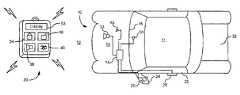
- FIG. 1is a system diagram of a vehicular integrated remote keyless-passive entry system according to a preferred embodiment of the present invention.
- FIG. 2is a schematic block diagram of the remote keyless-passive entry system according to a preferred embodiment of the present invention.
- FIG. 3is a timing diagram of signal exchanges in a preferred embodiment of the present invention.
- FIG. 4is a flowchart for conserving power in a portable communication device according to a first preferred embodiment of the present invention.
- FIG. 5is a flowchart for conserving power in a portable communication device according to a second preferred embodiment of the present invention.
- a vehicle 10has an interior region 11 and an exterior region 12 .
- a vehicle based communication module 14is mounted on said vehicle 10 such as in an engine compartment 15 or within a vehicle instrument panel 16 .
- the vehicle based communication module 14is coupled to a first exterior antenna 20 , which may be mounted in an exterior structure of the vehicle 10 such as a vehicle door 22 , a side view mirror housing 24 , or the engine compartment 15 . Additional transmitters or antennas may be mounted to the vehicle 10 at various passive entry zone locations remote from the vehicle based communication module 14 , if desired.
- the vehicle door 22provides a secure entry barrier between the interior region 11 and the exterior region 12 .
- the vehicle based communication module 14In a polling passive entry system, the vehicle based communication module 14 periodically broadcasts a wakeup signal for determining the presence of an authorized portable communication device 30 .
- the portable communication device 30such as a remote keyless entry (RKE) fob broadcasts RF signals to a vehicle based communication module 14 for remotely actuating various vehicle entry functions such as unlocking and locking the vehicle door 22 , unlatching a trunk 32 , and for activating and deactivating a vehicle alarm system 33 .
- a vehicle lock switch 34 and a vehicle unlock switch 36are commonly disposed on a face of the portable communication device 30 .
- the portable communication device 30may further include a trunk unlatch switch 38 and alarm switch 40 for activating and deactivating the vehicle alarm 33 .
- the portable communication device 30typically broadcasts the RF signals at a maximum power level that is regulated by the FCC. Based on the sensitivity of a respective receiver, the vehicle based communication module 14 receives the RF signal when the vehicle 10 (i.e., vehicle based communication module 14 ) is within the broadcasting range of the portable communication device 30 . The vehicle based communication module 14 determines the validity of the RF signal broadcast by the portable communication device 30 for actuating vehicle entry functions.
- the portable communication device 30includes additional receivers for combining passive entry functionality and active keyless entry functionality within the portable communication device 30 .
- FIG. 2illustrates a schematic block diagram of a preferred embodiment of the integrated two-way RKE and passive entry system.
- the integrated two-way RKE and passive entry systemis shown in co-pending application entitled “Integrated Passive Entry And Remote Keyless Entry System”, Ser. No. 10/999,503, filed Nov. 30, 2004, which is incorporated by reference herein.
- the vehicle based communication module 14includes a microcontroller 42 coupled to a LF transmitter 44 , a RF receiver 46 , and a RF transmitter 48 .
- additional LF transmitters or LF antennasmay be provided.
- the additional transmitters or antennasmay be located in the vehicle remotely from vehicle based communication module at an entry zone being monitored by a passive entry system, for example.
- a single LF transmitter 44may also use a plurality of LF antennas at respective locations within the vehicle 10 such as a LF antenna 50 deployed within the interior region 11 of the vehicle 10 in addition to LF antenna 20 deployed in the side view mirror housing 24 .
- a door module 52is coupled to microcontroller 42 for receiving door lock/unlock request signals from various devices including the vehicle based communication module 14 for remotely locking and unlocking a corresponding door lock.
- a RF antenna 45is coupled to RF receiver 46 as well as to RF transmitter 48 through a matching circuit 54 for transmitting challenge signals and for receiving response signals.
- Portable communication device 30includes a microcontroller 60 coupled to input buttons 61 that typically include separate push buttons for activating RKE commands for locking and unlocking doors, remotely starting or stopping an engine, panic alarm, and others.
- a RF transmitter 62is coupled to an antenna 63 through a matching network 64 .
- RKE commands initiated by depressing a push button 61are broadcast by the RF transmitter 62 and antenna 63 .
- a RF receiver 65is coupled to antenna 63 and microcontroller 60 for receiving UHF status messages broadcast by vehicle based communication module 14 , such as engine running status for a remote start function.
- a display 53is coupled to microcontroller 60 for displaying vehicle status data from a status message to a user.
- a LF receiver 67is coupled to the microcontroller 60 and to a LF antenna 68 for detecting wakeup signals broadcast from vehicle 10 .
- a battery 69 in the portable communication device 30supplies electrical power to all the other components of portable communication device 30 during normal operation.
- a typical polling passive entry sequencebegins by generating a LF wakeup signal to activate the LF receiver 67 in the portable communication device 30 via antennas 20 and 68 .
- the LF wakeup signalis also used to localize the portable communication device based on whether LF transmitter antenna 50 or any additional LF transmitter antenna generates the strongest received LF wakeup signal in portable communication device 30 .
- the LF wakeup signalhas a known format including an operation code for identifying the signal as a wakeup signal and preferably also including an antenna identifier unique to the antenna being used to transmit each LF wake-up signal. Localization of the portable communication device 30 is necessary to ensure that a person carrying an authorized portable communication device is properly located in the area where the passive function is being requested (e.g., located outside the door for activating a passive entry function or located in the passenger compartment).
- LF receiver 67preferably includes circuitry for measuring a received signal strength indicator (RSSI) at which the LF wakeup signals received.
- RSSIreceived signal strength indicator
- the awakened microcontroller 60stores the RSSI data as part of response data to be sent back to vehicle based communication module 14 .
- RF receiver 65is activated in order to receive an expected challenge signal from vehicle based communication module 14 as part of a conventional interrogation/response validation sequence.
- microcontroller 42 in vehicle based communication module 14generates a random number to be used as a seed number in a secret mathematical transformation that is also known to the microcontroller 60 in the portable communication device 30 .
- RF transmitter 48 in vehicle based communication module 14is used broadcast a UHF challenge signal including the random number.
- RF receiver 65 in the portable communication device 30receives the UHF challenge signal and the microcontroller 60 passes the random number through the known mathematical transformation.
- the resulting transformed numberis included in response data together with the RSSI signal and a portable communication device identifier for inclusion in a UHF response signal broadcast via RF transmitter 62 and antenna 63 .
- the UHF interrogation and response signalsare sent with a much shorter time delay than if they were sent at the low frequency.
- the interrogation and responsemay both be sent at 9.6k baud, for example.
- the UHF response signalis received by RF receiver 46 via antenna 45 in vehicle based communication module 14 and is processed by microcontroller 42 in a known manner. For instance, microcontroller 42 checks the transformed number as received from portable communication device 30 with its own results of the transformation and determines the UHF response signal to be valid if the transformed numbers match.
- Typical remote control commandsinclude locking all doors, unlocking a driver's door, unlocking all doors, unlocking a trunk, activating a panic alarm, remotely starting an engine, activating a climate control, deactivating an engine, deactivating a climate control, and requesting vehicle status data to be provided in a UHF status message.
- FIG. 3shows a first preferred embodiment for localizing a passive communication device in a passive entry sequence wherein it is desired to determine whether the passive communication device is in an exterior region of the vehicle or within an interior region of the vehicle.
- a first LF wakeup signal 55is generated from a first antenna preferentially transmitting to a first area with respect to the vehicle (e.g., outside the vehicle adjacent to a particular door or other closure such as a trunk).
- the base stationAfter waiting an amount of time sufficient to allow the portable communication device to awaken, the base station sends a challenge signal 57 via the base station RF transmitter and antenna.
- the portable communication device RF transmittersends a UHF response signal 59 .
- the responseincludes RSSI data showing strong reception. If outside the first area, then the RSSI data will reflect a weak signal. If the portable communication device is not close enough to the target area, the wakeup signal will not have been received and there will no response to the challenge signal at all.
- a LF wakeup signal 58is sent via a second LF antenna preferentially transmitting to a second area (e.g., inside the vehicle).
- a UHF challenge signal 66is sent via the RF transmitter in the base station. If a passive communication device was awakened in the desired location being polled, a UHF response signal 70 is sent from the passive communication device RF transmitter to the base station RF receiver. Various areas are polled to distinguish whether the portable communication device is within the interior region or exterior region of the vehicle such as near the driver's side or passenger's side of the vehicle.
- significant power drainmay occur if a portable communication device is left within the interior of the vehicle while the vehicle is locked and the vehicle based communication module actively broadcasts wakeup and interrogations signals which the portable communication device responds to.
- the portable communication device 30is commanded to enter a non-response state. All other respective portable communication devices associated with the passive entry system continue to operate in a response state.
- poweris maintained to the LF receiver 67 for receiving wakeup signals.
- the RF transmitter 62 of the portable communication device 30no response signal is transmitted by the RF transmitter 62 of the portable communication device 30 to the ongoing polling signals.
- This non-response stateis enabled when the RF transmitter 48 of the vehicle based communication module 14 broadcasts a lockout signal via antenna 45 to the portable communication device 30 in response a determination that the portable communication device 30 is within the interior of the vehicle 10 based on a last received response signal.
- the lockout signal(e.g., challenge signal with an op code commanding the non-response state be entered) is received by the RF receiver 65 via antenna 63 of the portable communication device 30 .
- the received lockout signalis provided to the microcontroller 60 where the microcontroller 60 thereafter enables the non-response state.
- the portable communication device 30 at predetermined time intervalsmay exit the non-response state and await a wakeup signal from the vehicle based communication module 14 for determining whether the portable communication device 30 is within the interior region 11 of the vehicle 10 .
- the microcontroller 42 of the vehicle based communication module 14may broadcast an exit signal to the portable communication device 30 to exit the non-response state (e.g., challenge signal with an op code to respond to the challenge signal) for determining whether the portable communication device 30 is within the interior region of the vehicle 10 . If the microcontroller 42 of the vehicle based communication module 14 determines that the portable communication device 30 is not within the interior region 11 of the vehicle 10 , then the portable communication device 30 will remain in the response state.
- the non-response statemay include a power down state. That is, either the portable communication device 30 will power down immediately upon receiving a lockout signal and no power will be provided to either of the transmitting or receiving devices of the portable communication device 30 .
- the portable communication devicemay be powered up at predetermined time intervals for determining whether at least one of a plurality of predetermined conditions has occurred for restoring the response state.
- a combined non-response state(e.g., where the portable communication device can receive signals but not transmit) and the power down state may be utilized.
- the portable communication device 30may first enter a non-response state when a determination is initially made that portable communication device is within the interior region 11 of the vehicle 10 . If a determination is made that the portable communication device 30 has remained within the interior region 11 of the vehicle 10 for the extended period of time, then the portable communication device 30 is commanded to power down. This may be initiated by the microcontroller 60 of the portable communication device 30 or the microcontroller 42 of the vehicle based communication module 14 requests the portable communication device 30 to power down and enter a sleep mode. The portable communication device 30 may thereafter periodically awaken from the sleep mode after a first predetermined period of time has elapsed.
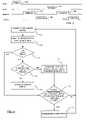
- FIG. 4illustrates a method of entering the non-response state according a first preferred embodiment of the present invention.
- a challenge signalis transmitted from the vehicle based communication module to a broadcast region around the vehicle.
- a broadcast regionincludes interior and exterior regions.
- the vehicle based communication moduleawaits a response from a portable communication device.
- step 73a determination is made whether a portable communication device has responded. If the determination is made, in step 73 , that a response is received from at least one portable communication device, then a determination is made in step 74 as to whether the portable communication device responding to the challenge signal is within an interior region of the vehicle or exterior region of the vehicle. If the determination is made in step 74 that the portable communication device is not within the interior region, then the passive entry system is activated in step 77 . If the determination is made that the portable communication device is within the interior region of the vehicle, then a lockout signal is broadcast by the vehicle based communication module to the portable communication device to enter a non-response state in step 75 .
- the non-response statemay include a power down state where the portable communication device neither receives nor transmits signals.
- the microcontroller of the vehicle based communication moduledetermines the location of the portable communication device as discussed earlier.
- the microcontrollerin response to determining the location of the portable communication device within the interior region broadcasts the lockout signal via the vehicle communication module's RF transmitter and antenna.
- step 76a determination is made whether a predetermined condition has occurred for exiting the non-response state.
- predetermined conditionsinclude being in a non-response state for an extended period of time, or actuation of a passive entry button such as door unlock or engine start.
- the portable communication devicemay exit the non-response state in response thereto for responding to a challenge signal for determining whether the portable communication device is still within the interior region of the vehicle. If no predetermined condition occurred in step 76 , then a return is made to step 71 .
- step 76If the determination is made in step 76 that at least one predetermined condition has occurred, then the portable communication device enters the response state in step 77 . A return to step 71 is made thereafter.
- FIG. 5illustrates a method of entering a non-response state according a second preferred embodiment of the present invention.
- the microcontroller of the vehicle based communication moduleupdates a lockout list.
- the lockout listincludes identifiers (e.g., ID codes) of respective portable communication devices that are authorized for vehicle entry, but the last known status indicates that the respective portable communication devices are within the interior region of the vehicle and are currently in either a non-response state or a power down state.
- the lockout listis updated each time a respective wakeup signal is broadcast or when the vehicle receives a RKE signal from the portable communication device.
- a respective portable communication devicemay be removed from the list when a determination is made that the device is removed from the vehicle, or the lock mechanism has been deactivated, or that the passive entry system has been deactivated, or that the portable communication device is transmitting a signal (i.e., an RKE signal).
- a challenge signalis transmitted from the vehicle based communication module to a broadcast region about the vehicle.
- a broadcast regionincludes interior and exterior regions.
- step 82the vehicle based communication module awaits a response from a portable communication device.
- step 83a determination is made whether any portable communication devices have responded to the challenge signal. If a determination is made that no respective portable communication devices responded, then a determination is made, in step 92 , as to whether any portable communication device is currently listed on the lockout list. This is performed to verify whether there are any portable communication devices currently in a non-response state or power down state, and if so, whether any conditions exist for commanding that they exit the non-response state. If a determination is made that no portable communication devices are currently on the lockout list, then a return is made to step 80 . If a respective portable communication device is currently on the lockout list, then a determination is made in step 86 as to whether at least one predetermined condition has occurred for exiting the response state.
- step 84determines whether the portable communication device responding to the challenge signal is within an interior region of the vehicle or exterior to the vehicle. If the determination is made in step 84 that the portable communication device is not within the interior region, then the passive entry system may be activated in step 87 , if appropriate. If the determination is made that the portable communication device is within the interior region of the vehicle, then a lockout signal is broadcast by the vehicle based communication module to the portable communication device to enter a non-response state in step 85 . The microcontroller of the vehicle based communication module determines the location of the portable communication device as discussed earlier. The microcontroller in response to determining that the portable communication device is within the interior region broadcasts the lockout signal via the vehicle communication module's RF transmitter and antenna.
- step 86the determination is made whether at least one predetermined condition has occurred for exiting the non-response state. If the determination is made that at least one predetermined condition has occurred, then the portable communication device enters the response state, in step 88 .
- a predetermined condition as discussed earliersignifies that either a vehicle function has been actuated or that the user of the vehicle is accessing the vehicle, and as result, the passive entry system is thereafter disabled. A return is made to step 80 to update the lockout list.
- step 89a determination is made in step 89 of whether the portable communication device is located within the interior region of the vehicle for an extended period of time.
- the purpose of determining whether the portable communication device is within the interior region for the extended period of timeis to determine whether to power down the portable communication device for conserving power.
- step 89If the determination made in step 89 is that the extended period of time has not elapsed indicating that the portable communication device has not been in the interior region continuously for the extended period of time, then a return is made to step 80 .
- step 90the portable communication device enters a power down state in step 90 .
- This determinationmay be made by the microcontroller of the portable communication device by monitoring the period of time that has elapsed while in the interior region of the vehicle, or alternatively, the microcontroller of the vehicle base communication module may record the length of time and broadcast a command to the portable communication device to enter the power down state.
- the microcontrollerWhen in the power down state, no power is provided to the receiver and transmitter of the portable communication device until at least one predetermined condition occurs. The microcontroller enters the power down state with only limited power provided to the microcontroller.
- the portable communication deviceis powered up after a predetermined period of time has elapsed.
- the microcontroller of the portable communication deviceawaits a predetermined period of time to elapse before powering up the portable communication device and enabling the response state in step 92 .
- a returnis then made to step 80 to await a wakeup signal and update the lockout list.
- the microcontroller of the portable communication devicemay power up the portable communication device and enter the response state prior to the predetermined period of time elapsing if the microcontroller determines that an RKE function on the portable communication device has been actuated. This implies that the user has retrieved the portable communication device and is actively initiating a RKE function via the portable communication device.
Landscapes
- Physics & Mathematics (AREA)
- General Physics & Mathematics (AREA)
- Engineering & Computer Science (AREA)
- Computer Networks & Wireless Communication (AREA)
- Mechanical Engineering (AREA)
- Lock And Its Accessories (AREA)
Abstract
Description
Claims (20)
Priority Applications (3)
| Application Number | Priority Date | Filing Date | Title |
|---|---|---|---|
| US11/129,159US7292137B2 (en) | 2005-05-13 | 2005-05-13 | Energy efficient passive entry system |
| DE102006016495ADE102006016495A1 (en) | 2005-05-13 | 2006-04-07 | Energy-efficient passive locking system |
| GB0609471AGB2426103B (en) | 2005-05-13 | 2006-05-12 | Energy efficient passive entry system |
Applications Claiming Priority (1)
| Application Number | Priority Date | Filing Date | Title |
|---|---|---|---|
| US11/129,159US7292137B2 (en) | 2005-05-13 | 2005-05-13 | Energy efficient passive entry system |
Publications (2)
| Publication Number | Publication Date |
|---|---|
| US20060255908A1 US20060255908A1 (en) | 2006-11-16 |
| US7292137B2true US7292137B2 (en) | 2007-11-06 |
Family
ID=36637410
Family Applications (1)
| Application Number | Title | Priority Date | Filing Date |
|---|---|---|---|
| US11/129,159Active2025-12-23US7292137B2 (en) | 2005-05-13 | 2005-05-13 | Energy efficient passive entry system |
Country Status (3)
| Country | Link |
|---|---|
| US (1) | US7292137B2 (en) |
| DE (1) | DE102006016495A1 (en) |
| GB (1) | GB2426103B (en) |
Cited By (16)
| Publication number | Priority date | Publication date | Assignee | Title |
|---|---|---|---|---|
| US20070085659A1 (en)* | 2005-10-14 | 2007-04-19 | Siemens Vdo Automotive Corporation | Sensor system with activation alert |
| US20070132554A1 (en)* | 2005-12-08 | 2007-06-14 | Siemens Vdo Automotive Corporation | Computer module for sensor system with activation alert |
| US20070268114A1 (en)* | 2006-05-17 | 2007-11-22 | Sony Deutschland Gmbh | Method for operating an electronic device, electronic device, and electronic assembly |
| US20080048827A1 (en)* | 2006-08-28 | 2008-02-28 | Alps Electric Co., Ltd. | Keyless entry system |
| US20080048846A1 (en)* | 2006-08-21 | 2008-02-28 | Denso Corporation | Wireless key and door remote control system |
| US20080143500A1 (en)* | 2006-12-15 | 2008-06-19 | Riad Ghabra | Method and apparatus for an anti-theft system against radio relay attack in passive keyless entry/start systems |
| US20080296926A1 (en)* | 2007-06-01 | 2008-12-04 | Gm Global Technology Operations, Inc. | Arms full vehicle closure activation apparatus and method |
| US20080297929A1 (en)* | 2005-11-29 | 2008-12-04 | Renault S.A.S. | Door Mounting Plate with Built-in Rear-View Mirror Function |
| US20100265047A1 (en)* | 2007-09-24 | 2010-10-21 | Markus Aunkofer | Method, device and system for exchanging information between a vehicle and a mobile id provider |
| US20110148573A1 (en)* | 2009-12-22 | 2011-06-23 | Lear Corporation | Passive entry system and method for a vehicle |
| US20110309922A1 (en)* | 2010-06-16 | 2011-12-22 | Lear Corporation | Low latency inside/outside determination for portable transmitter |
| US8473153B1 (en)* | 2011-12-22 | 2013-06-25 | Honda Motor Co., Ltd. | Key fob battery life preservation system and method |
| US8725330B2 (en) | 2010-06-02 | 2014-05-13 | Bryan Marc Failing | Increasing vehicle security |
| US9613475B2 (en)* | 2015-05-27 | 2017-04-04 | Nxp B.V. | Communications with interaction detection |
| US10269199B2 (en) | 2017-09-27 | 2019-04-23 | Honda Motor Co., Ltd. | System and method for providing energy efficient hands free vehicle door operation |
| US20190227142A1 (en)* | 2018-01-19 | 2019-07-25 | Toyota Jidosha Kabushiki Kaisha | In-vehicle communication device and communication method |
Families Citing this family (35)
| Publication number | Priority date | Publication date | Assignee | Title |
|---|---|---|---|---|
| JP4908868B2 (en)* | 2006-02-16 | 2012-04-04 | 本田技研工業株式会社 | Vehicle remote control apparatus and method |
| JP2009530519A (en)* | 2006-03-16 | 2009-08-27 | コンティネンタル オートモーティブ システムズ ユーエス, インコーポレイティッド | System and method for limiting interference to passive start and entry systems |
| JP2008045301A (en)* | 2006-08-11 | 2008-02-28 | Nissan Motor Co Ltd | Vehicle open / close control system and vehicle open / close control method |
| US7916004B2 (en)* | 2006-12-20 | 2011-03-29 | Dei Headquarters, Inc. | Security system with passive locking bypass |
| FR2913278B1 (en)* | 2007-03-01 | 2009-04-17 | Siemens Vdo Automotive Sas | METHOD FOR THE PROVISIONAL INHIBITION, IN ITS DETECTION IN A LOCKED VEHICLE, OF A PORTABLE REMOTE CONTROL BOX, IDENTIFIED, OF A HANDS-FREE ACCESS DEVICE |
| US7850078B2 (en)* | 2007-04-23 | 2010-12-14 | Lear Corporation | Remote control reactivation |
| US8451087B2 (en)* | 2007-12-25 | 2013-05-28 | Ford Global Technologies, Llc | Passive entry system for automotive vehicle doors |
| US20100304690A1 (en)* | 2009-05-29 | 2010-12-02 | Gm Global Technology Operations, Inc. | Method of passively detecting an approach to a vehicle |
| FR2959048B1 (en)* | 2010-04-20 | 2012-05-11 | Continental Automotive France | METHODS OF TRANSMITTING AND RECEIVING A RADIO FREQUENCY FRAME IN A REMOTE CONTROL SYSTEM OF A MOTOR VEHICLE |
| US8310364B2 (en)* | 2010-07-28 | 2012-11-13 | Versus Technology, Inc. | Real-time method and system for determining and validating location of a relocated mobile object or person in a tracking environment |
| FR2965434B1 (en)* | 2010-09-28 | 2015-12-11 | Valeo Securite Habitacle | METHOD OF PAIRING A MOBILE TELEPHONE WITH A MOTOR VEHICLE AND LOCKING / UNLOCKING ASSEMBLY |
| JP5218572B2 (en)* | 2011-01-07 | 2013-06-26 | 株式会社デンソー | In-vehicle device control system |
| US9126545B2 (en)* | 2011-02-25 | 2015-09-08 | GM Global Technology Operations LLC | Vehicle systems activation methods and applications |
| US9633499B2 (en)* | 2011-08-17 | 2017-04-25 | GM Global Technology Operations LLC | System and method for detecting presence of one or more user identification device |
| DE102012003015A1 (en)* | 2012-02-15 | 2013-08-22 | Audi Ag | Starting system for a motor vehicle, motor vehicle with a starting system and method for operating a starting system for a motor vehicle |
| US9520939B2 (en)* | 2013-03-06 | 2016-12-13 | Qualcomm Incorporated | Methods and apparatus for using visible light communications for controlling access to an area |
| DE102013203947A1 (en)* | 2013-03-07 | 2014-09-11 | Bayerische Motoren Werke Aktiengesellschaft | Identification transmitter for an access control system of an object |
| KR101430702B1 (en)* | 2013-10-16 | 2014-08-14 | 콘티넨탈 오토모티브 시스템 주식회사 | Method for detecting location of smartkey and apparatus thereof |
| DE102014020142B4 (en)* | 2013-12-05 | 2024-05-02 | Deutsche Post Ag | Access authorization with time window |
| DE102014109837A1 (en)* | 2014-07-14 | 2016-01-14 | Hella Kgaa Hueck & Co. | Method and hand-free access system for locating a user identification means and for data communication between the user identification means and a user device |
| US9710983B2 (en)* | 2015-01-29 | 2017-07-18 | GM Global Technology Operations LLC | Method and system for authenticating vehicle equipped with passive keyless system |
| JP6693208B2 (en)* | 2016-03-23 | 2020-05-13 | トヨタ自動車株式会社 | Smart key system |
| JP6347283B2 (en)* | 2016-10-12 | 2018-06-27 | マツダ株式会社 | Electronic key system |
| US10051435B2 (en)* | 2016-12-12 | 2018-08-14 | Denso International America, Inc. | Mobile device location system |
| JP6794931B2 (en)* | 2017-06-05 | 2020-12-02 | トヨタ自動車株式会社 | Vehicle control system |
| US10424956B2 (en)* | 2017-06-19 | 2019-09-24 | Lear Corporation | Methods and systems for handling passive entry passive start (PEPS) remote controller battery self-discharge |
| JP6595551B2 (en)* | 2017-09-20 | 2019-10-23 | 株式会社東海理化電機製作所 | Car sharing system |
| JP6812939B2 (en)* | 2017-09-27 | 2021-01-13 | トヨタ自動車株式会社 | Terminals, vehicle control systems, and vehicle control methods |
| JP2019065624A (en)* | 2017-10-03 | 2019-04-25 | 株式会社東海理化電機製作所 | Electronic key system |
| US11743806B2 (en)* | 2017-12-05 | 2023-08-29 | Ford Global Technologies, Llc | Method and apparatus for wireless communication suppression |
| US10793108B2 (en)* | 2018-11-09 | 2020-10-06 | Ford Global Technologies, Llc | Bluetooth-enabled key fob |
| US10800381B2 (en)* | 2018-12-20 | 2020-10-13 | Continental Automotive Systems, Inc. | Vehicle access system battery and security management via interface diversity |
| DE102019211792B4 (en)* | 2019-08-06 | 2025-08-07 | Continental Automotive Technologies GmbH | Access arrangement for a vehicle |
| EP3800093B1 (en)* | 2019-10-03 | 2024-08-07 | Ningbo Geely Automobile Research & Development Co. Ltd. | A central locking system for locking a vehicle, a vehicle system, a method for controlling a central locking system and a computer program |
| GB2594250B (en)* | 2020-04-20 | 2024-11-27 | Continental Automotive Tech Gmbh | Electronic device and method of responding to a trigger to wake up |
Citations (11)
| Publication number | Priority date | Publication date | Assignee | Title |
|---|---|---|---|---|
| US4688036A (en) | 1983-11-29 | 1987-08-18 | Nissan Motor Company, Limited | Keyless entry system for automotive vehicle with power consumption saving feature |
| EP0950784A2 (en) | 1998-04-16 | 1999-10-20 | James P. Burgess | Keyless entry system for vehicles in particular |
| US6034593A (en)* | 1998-07-31 | 2000-03-07 | Motorola, Inc. | Communication system and method for keyless-entry alarms |
| US6317035B1 (en)* | 1999-03-29 | 2001-11-13 | Mannesmann Vdo Ag | Apparatus and method for enabling a security device, in particular an access device for a motor vehicle |
| EP1211104A2 (en) | 2000-11-29 | 2002-06-05 | Trw Inc. | Vehicle communication for tire sensor initiation and vehicle keyless entry via a shared resource |
| US6570486B1 (en)* | 1999-04-09 | 2003-05-27 | Delphi Automotive Systems | Passive remote access control system |
| US6617961B1 (en)* | 1999-11-15 | 2003-09-09 | Strattec Security Corporation | Security system for a vehicle and method of operating same |
| US20050046546A1 (en)* | 2003-08-25 | 2005-03-03 | Alps Electric Co., Ltd. | Passive keyless entry device |
| US20050046568A1 (en)* | 2003-09-01 | 2005-03-03 | Omron Corporation | Wireless terminal position detecting device and method |
| US20050275511A1 (en) | 2004-06-09 | 2005-12-15 | Yi Luo | Remote keyless entry transmitter fob with RF analyzer |
| GB2415534A (en) | 2004-06-25 | 2005-12-28 | Lear Corp | Integrated passive entry transmitter/receiver |
- 2005
- 2005-05-13USUS11/129,159patent/US7292137B2/enactiveActive
- 2006
- 2006-04-07DEDE102006016495Apatent/DE102006016495A1/ennot_activeWithdrawn
- 2006-05-12GBGB0609471Apatent/GB2426103B/ennot_activeExpired - Fee Related
Patent Citations (11)
| Publication number | Priority date | Publication date | Assignee | Title |
|---|---|---|---|---|
| US4688036A (en) | 1983-11-29 | 1987-08-18 | Nissan Motor Company, Limited | Keyless entry system for automotive vehicle with power consumption saving feature |
| EP0950784A2 (en) | 1998-04-16 | 1999-10-20 | James P. Burgess | Keyless entry system for vehicles in particular |
| US6034593A (en)* | 1998-07-31 | 2000-03-07 | Motorola, Inc. | Communication system and method for keyless-entry alarms |
| US6317035B1 (en)* | 1999-03-29 | 2001-11-13 | Mannesmann Vdo Ag | Apparatus and method for enabling a security device, in particular an access device for a motor vehicle |
| US6570486B1 (en)* | 1999-04-09 | 2003-05-27 | Delphi Automotive Systems | Passive remote access control system |
| US6617961B1 (en)* | 1999-11-15 | 2003-09-09 | Strattec Security Corporation | Security system for a vehicle and method of operating same |
| EP1211104A2 (en) | 2000-11-29 | 2002-06-05 | Trw Inc. | Vehicle communication for tire sensor initiation and vehicle keyless entry via a shared resource |
| US20050046546A1 (en)* | 2003-08-25 | 2005-03-03 | Alps Electric Co., Ltd. | Passive keyless entry device |
| US20050046568A1 (en)* | 2003-09-01 | 2005-03-03 | Omron Corporation | Wireless terminal position detecting device and method |
| US20050275511A1 (en) | 2004-06-09 | 2005-12-15 | Yi Luo | Remote keyless entry transmitter fob with RF analyzer |
| GB2415534A (en) | 2004-06-25 | 2005-12-28 | Lear Corp | Integrated passive entry transmitter/receiver |
Cited By (32)
| Publication number | Priority date | Publication date | Assignee | Title |
|---|---|---|---|---|
| US20070085659A1 (en)* | 2005-10-14 | 2007-04-19 | Siemens Vdo Automotive Corporation | Sensor system with activation alert |
| US20080297929A1 (en)* | 2005-11-29 | 2008-12-04 | Renault S.A.S. | Door Mounting Plate with Built-in Rear-View Mirror Function |
| US7889074B2 (en)* | 2005-12-08 | 2011-02-15 | Continental Automotive Systems Us, Inc. | Computer module for sensor system with activation alert |
| US20070132554A1 (en)* | 2005-12-08 | 2007-06-14 | Siemens Vdo Automotive Corporation | Computer module for sensor system with activation alert |
| US20070268114A1 (en)* | 2006-05-17 | 2007-11-22 | Sony Deutschland Gmbh | Method for operating an electronic device, electronic device, and electronic assembly |
| US7720513B2 (en)* | 2006-05-17 | 2010-05-18 | Sony Deutschland Gmbh | Method for operating an electronic device, electronic device, and electronic assembly |
| US20080048846A1 (en)* | 2006-08-21 | 2008-02-28 | Denso Corporation | Wireless key and door remote control system |
| US7629876B2 (en)* | 2006-08-21 | 2009-12-08 | Denso Corporation | Wireless key and door remote control system |
| US20080048827A1 (en)* | 2006-08-28 | 2008-02-28 | Alps Electric Co., Ltd. | Keyless entry system |
| US8044768B2 (en)* | 2006-08-28 | 2011-10-25 | Alps Electric Co., Ltd. | Keyless entry system using communication via human body |
| US20080143500A1 (en)* | 2006-12-15 | 2008-06-19 | Riad Ghabra | Method and apparatus for an anti-theft system against radio relay attack in passive keyless entry/start systems |
| US7791457B2 (en)* | 2006-12-15 | 2010-09-07 | Lear Corporation | Method and apparatus for an anti-theft system against radio relay attack in passive keyless entry/start systems |
| US8091280B2 (en)* | 2007-06-01 | 2012-01-10 | GM Global Technology Operations LLC | Arms full vehicle closure activation apparatus and method |
| US20080296926A1 (en)* | 2007-06-01 | 2008-12-04 | Gm Global Technology Operations, Inc. | Arms full vehicle closure activation apparatus and method |
| US20100265047A1 (en)* | 2007-09-24 | 2010-10-21 | Markus Aunkofer | Method, device and system for exchanging information between a vehicle and a mobile id provider |
| US8653955B2 (en) | 2007-09-24 | 2014-02-18 | Continental Automotive Gmbh | Method, device and system for exchanging information between a vehicle and a mobile ID provider |
| US8284020B2 (en) | 2009-12-22 | 2012-10-09 | Lear Corporation | Passive entry system and method for a vehicle |
| US20110148573A1 (en)* | 2009-12-22 | 2011-06-23 | Lear Corporation | Passive entry system and method for a vehicle |
| US9393878B1 (en) | 2010-06-02 | 2016-07-19 | Bryan Marc Failing | Energy transfer with vehicles |
| US9114719B1 (en) | 2010-06-02 | 2015-08-25 | Bryan Marc Failing | Increasing vehicle security |
| US11186192B1 (en) | 2010-06-02 | 2021-11-30 | Bryan Marc Failing | Improving energy transfer with vehicles |
| US10124691B1 (en) | 2010-06-02 | 2018-11-13 | Bryan Marc Failing | Energy transfer with vehicles |
| US8725330B2 (en) | 2010-06-02 | 2014-05-13 | Bryan Marc Failing | Increasing vehicle security |
| US8841881B2 (en) | 2010-06-02 | 2014-09-23 | Bryan Marc Failing | Energy transfer with vehicles |
| US20110309922A1 (en)* | 2010-06-16 | 2011-12-22 | Lear Corporation | Low latency inside/outside determination for portable transmitter |
| US8427289B2 (en)* | 2010-06-16 | 2013-04-23 | Lear Corporation | Low latency inside/outside determination for portable transmitter |
| CN102402844A (en)* | 2010-06-16 | 2012-04-04 | 李尔公司 | Low Latency Internal/External Determination for Portable Transmitters |
| US8473153B1 (en)* | 2011-12-22 | 2013-06-25 | Honda Motor Co., Ltd. | Key fob battery life preservation system and method |
| US9613475B2 (en)* | 2015-05-27 | 2017-04-04 | Nxp B.V. | Communications with interaction detection |
| US10269199B2 (en) | 2017-09-27 | 2019-04-23 | Honda Motor Co., Ltd. | System and method for providing energy efficient hands free vehicle door operation |
| US20190227142A1 (en)* | 2018-01-19 | 2019-07-25 | Toyota Jidosha Kabushiki Kaisha | In-vehicle communication device and communication method |
| US10527707B2 (en)* | 2018-01-19 | 2020-01-07 | Toyota Jidosha Kabushiki Kaisha | In-vehicle communication device and communication method |
Also Published As
| Publication number | Publication date |
|---|---|
| GB0609471D0 (en) | 2006-06-21 |
| GB2426103A (en) | 2006-11-15 |
| GB2426103B (en) | 2007-05-16 |
| DE102006016495A1 (en) | 2006-11-23 |
| US20060255908A1 (en) | 2006-11-16 |
Similar Documents
| Publication | Publication Date | Title |
|---|---|---|
| US7292137B2 (en) | Energy efficient passive entry system | |
| US7388466B2 (en) | Integrated passive entry and remote keyless entry system | |
| US8531268B2 (en) | Passive entry system for an automotive vehicle | |
| US7629873B2 (en) | Method and apparatus for configuring passive entry system operation modes | |
| KR100957297B1 (en) | Smart key detection system | |
| US7015791B2 (en) | Keyless entry module and method | |
| CN111674358A (en) | Keyless entry system and control method thereof | |
| US8054158B2 (en) | On-vehicle equipment control system | |
| KR101771376B1 (en) | Vehicle control system to prevent relay attack | |
| US7394350B2 (en) | Power-saving on-vehicle controller | |
| US5831520A (en) | Anti-lockout smart key system | |
| US6963794B2 (en) | Locking system for a motor vehicle | |
| US6489886B2 (en) | Security system to prevent unauthorized starting of the engine of a vehicle | |
| US6191703B1 (en) | Remote convience system and method with proximity-based disablement RFO preventing inadvertent function activation | |
| US20090243795A1 (en) | Automotive passive entry system and method of operating same | |
| JP2001295524A (en) | Control device | |
| JP4022913B2 (en) | Wireless device | |
| JP2001336321A (en) | Control device | |
| US7656270B2 (en) | Keyless entry device with passive and active entry modes | |
| US7009491B2 (en) | Dual purpose vehicle key fob for training tire pressure sensors | |
| JP2005320708A (en) | Electronic key system, electronic key and transmitter | |
| US20020149469A1 (en) | Single point failure avoidance for a keyless passive entry and immobilizer system | |
| WO2000060374A1 (en) | Passively powered, portable remote device | |
| GB2592851A (en) | Key fob | |
| EP1775184B1 (en) | Vehicle door unlock control system |
Legal Events
| Date | Code | Title | Description |
|---|---|---|---|
| AS | Assignment | Owner name:LEAR CORPORATION, MICHIGAN Free format text:ASSIGNMENT OF ASSIGNORS INTEREST;ASSIGNORS:GILBERT, CARL L.;GHABRA, RIAD;CHANNAPPA, SHUBHA;REEL/FRAME:016571/0627 Effective date:20050513 | |
| STCF | Information on status: patent grant | Free format text:PATENTED CASE | |
| AS | Assignment | Owner name:JPMORGAN CHASE BANK, N.A., AS ADMINISTRATIVE AGENT Free format text:GRANT OF FIRST LIEN SECURITY INTEREST IN PATENT RIGHTS;ASSIGNOR:LEAR CORPORATION;REEL/FRAME:023519/0267 Effective date:20091109 Owner name:JPMORGAN CHASE BANK, N.A., AS ADMINISTRATIVE AGENT Free format text:GRANT OF SECOND LIEN SECURITY INTEREST IN PATENT RIGHTS;ASSIGNOR:LEAR CORPORATION;REEL/FRAME:023519/0626 Effective date:20091109 | |
| FPAY | Fee payment | Year of fee payment:4 | |
| AS | Assignment | Owner name:JPMORGAN CAHSE BANK, N.A., AS AGENT, ILLINOIS Free format text:SECURITY INTEREST;ASSIGNOR:LEAR CORPORATION;REEL/FRAME:030076/0016 Effective date:20130130 Owner name:JPMORGAN CHASE BANK, N.A., AS AGENT, ILLINOIS Free format text:SECURITY INTEREST;ASSIGNOR:LEAR CORPORATION;REEL/FRAME:030076/0016 Effective date:20130130 | |
| AS | Assignment | Owner name:LEAR CORPORATION, MICHIGAN Free format text:RELEASE BY SECURED PARTY;ASSIGNOR:JPMORGAN CHASE BANK, N.A.;REEL/FRAME:032770/0843 Effective date:20100830 | |
| REMI | Maintenance fee reminder mailed | ||
| FPAY | Fee payment | Year of fee payment:8 | |
| SULP | Surcharge for late payment | Year of fee payment:7 | |
| AS | Assignment | Owner name:LEAR CORPORATION, MICHIGAN Free format text:RELEASE BY SECURED PARTY;ASSIGNOR:JPMORGAN CHASE BANK, N.A., AS AGENT;REEL/FRAME:037701/0340 Effective date:20160104 Owner name:LEAR CORPORATION, MICHIGAN Free format text:RELEASE BY SECURED PARTY;ASSIGNOR:JPMORGAN CHASE BANK, N.A., AS AGENT;REEL/FRAME:037701/0180 Effective date:20160104 Owner name:LEAR CORPORATION, MICHIGAN Free format text:RELEASE BY SECURED PARTY;ASSIGNOR:JPMORGAN CHASE BANK, N.A., AS AGENT;REEL/FRAME:037701/0251 Effective date:20160104 | |
| AS | Assignment | Owner name:LEAR CORPORATION, MICHIGAN Free format text:RELEASE BY SECURED PARTY;ASSIGNOR:JPMORGAN CHASE BANK, N.A., AS AGENT;REEL/FRAME:037702/0911 Effective date:20160104 | |
| MAFP | Maintenance fee payment | Free format text:PAYMENT OF MAINTENANCE FEE, 12TH YEAR, LARGE ENTITY (ORIGINAL EVENT CODE: M1553); ENTITY STATUS OF PATENT OWNER: LARGE ENTITY Year of fee payment:12 |