US7291191B2 - Fuel cell cartridge filters and pressure relief - Google Patents
Fuel cell cartridge filters and pressure reliefDownload PDFInfo
- Publication number
- US7291191B2 US7291191B2US11/229,049US22904905AUS7291191B2US 7291191 B2US7291191 B2US 7291191B2US 22904905 AUS22904905 AUS 22904905AUS 7291191 B2US7291191 B2US 7291191B2
- Authority
- US
- United States
- Prior art keywords
- storage device
- fuel source
- bladder
- hydrogen fuel
- hydrogen
- Prior art date
- Legal status (The legal status is an assumption and is not a legal conclusion. Google has not performed a legal analysis and makes no representation as to the accuracy of the status listed.)
- Expired - Lifetime
Links
- 239000000446fuelSubstances0.000titleclaimsabstractdescription434
- 238000003860storageMethods0.000claimsabstractdescription286
- UFHFLCQGNIYNRP-UHFFFAOYSA-NHydrogenChemical compound[H][H]UFHFLCQGNIYNRP-UHFFFAOYSA-N0.000claimsabstractdescription195
- 239000001257hydrogenSubstances0.000claimsabstractdescription194
- 229910052739hydrogenInorganic materials0.000claimsabstractdescription194
- 230000013011matingEffects0.000claimsabstractdescription96
- 238000012546transferMethods0.000claimsabstractdescription22
- OKKJLVBELUTLKV-UHFFFAOYSA-NMethanolChemical compoundOCOKKJLVBELUTLKV-UHFFFAOYSA-N0.000claimsdescription129
- 239000000463materialSubstances0.000claimsdescription13
- 239000007789gasSubstances0.000claimsdescription12
- 239000012530fluidSubstances0.000claimsdescription10
- 230000002209hydrophobic effectEffects0.000claimsdescription9
- 238000009835boilingMethods0.000claimsdescription4
- 230000007423decreaseEffects0.000claimsdescription4
- 229910052751metalInorganic materials0.000claimsdescription4
- 239000002184metalSubstances0.000claimsdescription4
- 239000002245particleSubstances0.000claimsdescription2
- QVGXLLKOCUKJST-UHFFFAOYSA-Natomic oxygenChemical compound[O]QVGXLLKOCUKJST-UHFFFAOYSA-N0.000description30
- 239000001301oxygenSubstances0.000description30
- 229910052760oxygenInorganic materials0.000description30
- 239000003570airSubstances0.000description27
- 239000003054catalystSubstances0.000description25
- 238000009826distributionMethods0.000description20
- 229930195733hydrocarbonNatural products0.000description15
- 150000002430hydrocarbonsChemical class0.000description15
- 239000007788liquidSubstances0.000description15
- 239000012528membraneSubstances0.000description15
- 239000000203mixtureSubstances0.000description15
- 239000004215Carbon black (E152)Substances0.000description14
- LFQSCWFLJHTTHZ-UHFFFAOYSA-NEthanolChemical compoundCCOLFQSCWFLJHTTHZ-UHFFFAOYSA-N0.000description14
- 239000004033plasticSubstances0.000description13
- 229920003023plasticPolymers0.000description13
- 230000006854communicationEffects0.000description12
- 238000004891communicationMethods0.000description12
- CURLTUGMZLYLDI-UHFFFAOYSA-NCarbon dioxideChemical compoundO=C=OCURLTUGMZLYLDI-UHFFFAOYSA-N0.000description10
- 238000000034methodMethods0.000description10
- XLYOFNOQVPJJNP-UHFFFAOYSA-NwaterSubstancesOXLYOFNOQVPJJNP-UHFFFAOYSA-N0.000description9
- 150000002431hydrogenChemical class0.000description8
- 239000003063flame retardantSubstances0.000description7
- 239000006260foamSubstances0.000description7
- 230000036541healthEffects0.000description7
- 150000002500ionsChemical class0.000description7
- 230000008569processEffects0.000description7
- 239000000126substanceSubstances0.000description7
- MYMOFIZGZYHOMD-UHFFFAOYSA-NDioxygenChemical compoundO=OMYMOFIZGZYHOMD-UHFFFAOYSA-N0.000description6
- PXHVJJICTQNCMI-UHFFFAOYSA-NNickelChemical compound[Ni]PXHVJJICTQNCMI-UHFFFAOYSA-N0.000description6
- ATUOYWHBWRKTHZ-UHFFFAOYSA-NPropaneChemical compoundCCCATUOYWHBWRKTHZ-UHFFFAOYSA-N0.000description6
- 239000003086colorantSubstances0.000description6
- 238000013461designMethods0.000description6
- 229910001882dioxygenInorganic materials0.000description6
- 239000003205fragranceSubstances0.000description6
- 238000007726management methodMethods0.000description6
- 238000005201scrubbingMethods0.000description6
- UGFAIRIUMAVXCW-UHFFFAOYSA-NCarbon monoxideChemical compound[O+]#[C-]UGFAIRIUMAVXCW-UHFFFAOYSA-N0.000description5
- 229910002092carbon dioxideInorganic materials0.000description5
- 239000001569carbon dioxideSubstances0.000description5
- 229910002091carbon monoxideInorganic materials0.000description5
- 239000003502gasolineSubstances0.000description5
- VNWKTOKETHGBQD-UHFFFAOYSA-NmethaneChemical compoundCVNWKTOKETHGBQD-UHFFFAOYSA-N0.000description5
- BASFCYQUMIYNBI-UHFFFAOYSA-NplatinumChemical compound[Pt]BASFCYQUMIYNBI-UHFFFAOYSA-N0.000description5
- QGZKDVFQNNGYKY-UHFFFAOYSA-NAmmoniaChemical compoundNQGZKDVFQNNGYKY-UHFFFAOYSA-N0.000description4
- OKTJSMMVPCPJKN-UHFFFAOYSA-NCarbonChemical compound[C]OKTJSMMVPCPJKN-UHFFFAOYSA-N0.000description4
- NBIIXXVUZAFLBC-UHFFFAOYSA-NPhosphoric acidChemical compoundOP(O)(O)=ONBIIXXVUZAFLBC-UHFFFAOYSA-N0.000description4
- 230000008859changeEffects0.000description4
- 238000004140cleaningMethods0.000description4
- ORTQZVOHEJQUHG-UHFFFAOYSA-Lcopper(II) chlorideChemical compoundCl[Cu]ClORTQZVOHEJQUHG-UHFFFAOYSA-L0.000description4
- 238000005516engineering processMethods0.000description4
- 238000004519manufacturing processMethods0.000description4
- 239000000047productSubstances0.000description4
- 230000032258transportEffects0.000description4
- 239000004809TeflonSubstances0.000description3
- 229920006362Teflon®Polymers0.000description3
- 230000008901benefitEffects0.000description3
- 238000006243chemical reactionMethods0.000description3
- 230000008878couplingEffects0.000description3
- 238000010168coupling processMethods0.000description3
- 238000005859coupling reactionMethods0.000description3
- 230000003247decreasing effectEffects0.000description3
- -1hydrogen ionsChemical class0.000description3
- 230000007246mechanismEffects0.000description3
- 229910052759nickelInorganic materials0.000description3
- 239000007800oxidant agentSubstances0.000description3
- 238000009428plumbingMethods0.000description3
- 239000001294propaneSubstances0.000description3
- RWSOTUBLDIXVET-UHFFFAOYSA-NDihydrogen sulfideChemical compoundSRWSOTUBLDIXVET-UHFFFAOYSA-N0.000description2
- 239000002250absorbentSubstances0.000description2
- 230000002745absorbentEffects0.000description2
- 229910000147aluminium phosphateInorganic materials0.000description2
- 239000012080ambient airSubstances0.000description2
- 229910021529ammoniaInorganic materials0.000description2
- 239000001273butaneSubstances0.000description2
- 229910052799carbonInorganic materials0.000description2
- 230000003197catalytic effectEffects0.000description2
- 239000000356contaminantSubstances0.000description2
- 230000006378damageEffects0.000description2
- VWTINHYPRWEBQY-UHFFFAOYSA-NdenatoniumChemical compound[O-]C(=O)C1=CC=CC=C1.C=1C=CC=CC=1C[N+](CC)(CC)CC(=O)NC1=C(C)C=CC=C1CVWTINHYPRWEBQY-UHFFFAOYSA-N0.000description2
- 238000009792diffusion processMethods0.000description2
- 230000009977dual effectEffects0.000description2
- 229920001971elastomerPolymers0.000description2
- 238000003487electrochemical reactionMethods0.000description2
- DNJIEGIFACGWOD-UHFFFAOYSA-NethanethiolChemical compoundCCSDNJIEGIFACGWOD-UHFFFAOYSA-N0.000description2
- 238000010438heat treatmentMethods0.000description2
- 125000004435hydrogen atomChemical group[H]*0.000description2
- 229910000037hydrogen sulfideInorganic materials0.000description2
- 238000005342ion exchangeMethods0.000description2
- IJDNQMDRQITEOD-UHFFFAOYSA-Nn-butaneChemical compoundCCCCIJDNQMDRQITEOD-UHFFFAOYSA-N0.000description2
- OFBQJSOFQDEBGM-UHFFFAOYSA-Nn-pentaneNatural productsCCCCCOFBQJSOFQDEBGM-UHFFFAOYSA-N0.000description2
- 239000003345natural gasSubstances0.000description2
- 229910052697platinumInorganic materials0.000description2
- 239000005518polymer electrolyteSubstances0.000description2
- 239000005060rubberSubstances0.000description2
- 238000012360testing methodMethods0.000description2
- 230000001052transient effectEffects0.000description2
- GETQZCLCWQTVFV-UHFFFAOYSA-NtrimethylamineChemical compoundCN(C)CGETQZCLCWQTVFV-UHFFFAOYSA-N0.000description2
- 230000000007visual effectEffects0.000description2
- 229920000049Carbon (fiber)Polymers0.000description1
- BVKZGUZCCUSVTD-UHFFFAOYSA-LCarbonateChemical compound[O-]C([O-])=OBVKZGUZCCUSVTD-UHFFFAOYSA-L0.000description1
- QXNVGIXVLWOKEQ-UHFFFAOYSA-NDisodiumChemical class[Na][Na]QXNVGIXVLWOKEQ-UHFFFAOYSA-N0.000description1
- HMEKVHWROSNWPD-UHFFFAOYSA-NErioglaucine AChemical compound[NH4+].[NH4+].C=1C=C(C(=C2C=CC(C=C2)=[N+](CC)CC=2C=C(C=CC=2)S([O-])(=O)=O)C=2C(=CC=CC=2)S([O-])(=O)=O)C=CC=1N(CC)CC1=CC=CC(S([O-])(=O)=O)=C1HMEKVHWROSNWPD-UHFFFAOYSA-N0.000description1
- HBBGRARXTFLTSG-UHFFFAOYSA-NLithium ionChemical compound[Li+]HBBGRARXTFLTSG-UHFFFAOYSA-N0.000description1
- 239000004952PolyamideSubstances0.000description1
- 239000004695Polyether sulfoneSubstances0.000description1
- KJTLSVCANCCWHF-UHFFFAOYSA-NRutheniumChemical compound[Ru]KJTLSVCANCCWHF-UHFFFAOYSA-N0.000description1
- 239000003082abrasive agentSubstances0.000description1
- 230000002411adverseEffects0.000description1
- 125000001931aliphatic groupChemical group0.000description1
- 230000004075alterationEffects0.000description1
- 229910052782aluminiumInorganic materials0.000description1
- XAGFODPZIPBFFR-UHFFFAOYSA-NaluminiumChemical compound[Al]XAGFODPZIPBFFR-UHFFFAOYSA-N0.000description1
- 238000013459approachMethods0.000description1
- 230000006399behaviorEffects0.000description1
- 230000007175bidirectional communicationEffects0.000description1
- 239000004161brilliant blue FCFSubstances0.000description1
- 235000012745brilliant blue FCFNutrition0.000description1
- 239000006227byproductSubstances0.000description1
- 239000004917carbon fiberSubstances0.000description1
- 239000000919ceramicSubstances0.000description1
- 230000000295complement effectEffects0.000description1
- 239000002131composite materialSubstances0.000description1
- 150000001875compoundsChemical class0.000description1
- 238000010276constructionMethods0.000description1
- 238000001816coolingMethods0.000description1
- 238000005336crackingMethods0.000description1
- 229960003280cupric chlorideDrugs0.000description1
- 230000007547defectEffects0.000description1
- 229960001610denatonium benzoateDrugs0.000description1
- 238000011161developmentMethods0.000description1
- 239000003814drugSubstances0.000description1
- 229940079593drugDrugs0.000description1
- 230000005611electricityEffects0.000description1
- 239000004744fabricSubstances0.000description1
- 239000000989food dyeSubstances0.000description1
- 230000006870functionEffects0.000description1
- 230000006872improvementEffects0.000description1
- 238000002372labellingMethods0.000description1
- 239000004816latexSubstances0.000description1
- 229920000126latexPolymers0.000description1
- 229910001416lithium ionInorganic materials0.000description1
- 239000011159matrix materialSubstances0.000description1
- 239000012229microporous materialSubstances0.000description1
- 230000009965odorless effectEffects0.000description1
- 239000003921oilSubstances0.000description1
- 230000003287optical effectEffects0.000description1
- 231100000572poisoningToxicity0.000description1
- 230000000607poisoning effectEffects0.000description1
- 229920002647polyamidePolymers0.000description1
- 239000004417polycarbonateSubstances0.000description1
- 229920000515polycarbonatePolymers0.000description1
- 229920006393polyether sulfonePolymers0.000description1
- 229920002635polyurethanePolymers0.000description1
- 239000004814polyurethaneSubstances0.000description1
- 239000011148porous materialSubstances0.000description1
- 239000012286potassium permanganateSubstances0.000description1
- 230000005855radiationEffects0.000description1
- 238000002407reformingMethods0.000description1
- 238000009419refurbishmentMethods0.000description1
- 230000003716rejuvenationEffects0.000description1
- 230000004044responseEffects0.000description1
- 229910052707rutheniumInorganic materials0.000description1
- 239000000523sampleSubstances0.000description1
- 239000007787solidSubstances0.000description1
- 229910001220stainless steelInorganic materials0.000description1
- 239000010935stainless steelSubstances0.000description1
- 230000001629suppressionEffects0.000description1
- 238000002834transmittanceMethods0.000description1
- 238000011144upstream manufacturingMethods0.000description1
- 238000013022ventingMethods0.000description1
- 239000002699waste materialSubstances0.000description1
Images


Classifications
- H—ELECTRICITY
- H01—ELECTRIC ELEMENTS
- H01M—PROCESSES OR MEANS, e.g. BATTERIES, FOR THE DIRECT CONVERSION OF CHEMICAL ENERGY INTO ELECTRICAL ENERGY
- H01M8/00—Fuel cells; Manufacture thereof
- H01M8/04—Auxiliary arrangements, e.g. for control of pressure or for circulation of fluids
- H01M8/04082—Arrangements for control of reactant parameters, e.g. pressure or concentration
- H01M8/04201—Reactant storage and supply, e.g. means for feeding, pipes
- H01M8/04208—Cartridges, cryogenic media or cryogenic reservoirs
- F—MECHANICAL ENGINEERING; LIGHTING; HEATING; WEAPONS; BLASTING
- F17—STORING OR DISTRIBUTING GASES OR LIQUIDS
- F17C—VESSELS FOR CONTAINING OR STORING COMPRESSED, LIQUEFIED OR SOLIDIFIED GASES; FIXED-CAPACITY GAS-HOLDERS; FILLING VESSELS WITH, OR DISCHARGING FROM VESSELS, COMPRESSED, LIQUEFIED, OR SOLIDIFIED GASES
- F17C3/00—Vessels not under pressure
- H—ELECTRICITY
- H01—ELECTRIC ELEMENTS
- H01M—PROCESSES OR MEANS, e.g. BATTERIES, FOR THE DIRECT CONVERSION OF CHEMICAL ENERGY INTO ELECTRICAL ENERGY
- H01M16/00—Structural combinations of different types of electrochemical generators
- H01M16/003—Structural combinations of different types of electrochemical generators of fuel cells with other electrochemical devices, e.g. capacitors, electrolysers
- H01M16/006—Structural combinations of different types of electrochemical generators of fuel cells with other electrochemical devices, e.g. capacitors, electrolysers of fuel cells with rechargeable batteries
- H—ELECTRICITY
- H01—ELECTRIC ELEMENTS
- H01M—PROCESSES OR MEANS, e.g. BATTERIES, FOR THE DIRECT CONVERSION OF CHEMICAL ENERGY INTO ELECTRICAL ENERGY
- H01M8/00—Fuel cells; Manufacture thereof
- H01M8/04—Auxiliary arrangements, e.g. for control of pressure or for circulation of fluids
- H01M8/04082—Arrangements for control of reactant parameters, e.g. pressure or concentration
- H01M8/04186—Arrangements for control of reactant parameters, e.g. pressure or concentration of liquid-charged or electrolyte-charged reactants
- H—ELECTRICITY
- H01—ELECTRIC ELEMENTS
- H01M—PROCESSES OR MEANS, e.g. BATTERIES, FOR THE DIRECT CONVERSION OF CHEMICAL ENERGY INTO ELECTRICAL ENERGY
- H01M8/00—Fuel cells; Manufacture thereof
- H01M8/04—Auxiliary arrangements, e.g. for control of pressure or for circulation of fluids
- H01M8/04082—Arrangements for control of reactant parameters, e.g. pressure or concentration
- H01M8/04201—Reactant storage and supply, e.g. means for feeding, pipes
- H—ELECTRICITY
- H01—ELECTRIC ELEMENTS
- H01M—PROCESSES OR MEANS, e.g. BATTERIES, FOR THE DIRECT CONVERSION OF CHEMICAL ENERGY INTO ELECTRICAL ENERGY
- H01M8/00—Fuel cells; Manufacture thereof
- H01M8/04—Auxiliary arrangements, e.g. for control of pressure or for circulation of fluids
- H01M8/04298—Processes for controlling fuel cells or fuel cell systems
- H01M8/04694—Processes for controlling fuel cells or fuel cell systems characterised by variables to be controlled
- H01M8/04746—Pressure; Flow
- H01M8/04776—Pressure; Flow at auxiliary devices, e.g. reformer, compressor, burner
- F—MECHANICAL ENGINEERING; LIGHTING; HEATING; WEAPONS; BLASTING
- F17—STORING OR DISTRIBUTING GASES OR LIQUIDS
- F17C—VESSELS FOR CONTAINING OR STORING COMPRESSED, LIQUEFIED OR SOLIDIFIED GASES; FIXED-CAPACITY GAS-HOLDERS; FILLING VESSELS WITH, OR DISCHARGING FROM VESSELS, COMPRESSED, LIQUEFIED, OR SOLIDIFIED GASES
- F17C2201/00—Vessel construction, in particular geometry, arrangement or size
- F17C2201/01—Shape
- F17C2201/0128—Shape spherical or elliptical
- F—MECHANICAL ENGINEERING; LIGHTING; HEATING; WEAPONS; BLASTING
- F17—STORING OR DISTRIBUTING GASES OR LIQUIDS
- F17C—VESSELS FOR CONTAINING OR STORING COMPRESSED, LIQUEFIED OR SOLIDIFIED GASES; FIXED-CAPACITY GAS-HOLDERS; FILLING VESSELS WITH, OR DISCHARGING FROM VESSELS, COMPRESSED, LIQUEFIED, OR SOLIDIFIED GASES
- F17C2201/00—Vessel construction, in particular geometry, arrangement or size
- F17C2201/01—Shape
- F17C2201/0147—Shape complex
- F17C2201/0157—Polygonal
- F—MECHANICAL ENGINEERING; LIGHTING; HEATING; WEAPONS; BLASTING
- F17—STORING OR DISTRIBUTING GASES OR LIQUIDS
- F17C—VESSELS FOR CONTAINING OR STORING COMPRESSED, LIQUEFIED OR SOLIDIFIED GASES; FIXED-CAPACITY GAS-HOLDERS; FILLING VESSELS WITH, OR DISCHARGING FROM VESSELS, COMPRESSED, LIQUEFIED, OR SOLIDIFIED GASES
- F17C2201/00—Vessel construction, in particular geometry, arrangement or size
- F17C2201/01—Shape
- F17C2201/0147—Shape complex
- F17C2201/0166—Shape complex divided in several chambers
- F—MECHANICAL ENGINEERING; LIGHTING; HEATING; WEAPONS; BLASTING
- F17—STORING OR DISTRIBUTING GASES OR LIQUIDS
- F17C—VESSELS FOR CONTAINING OR STORING COMPRESSED, LIQUEFIED OR SOLIDIFIED GASES; FIXED-CAPACITY GAS-HOLDERS; FILLING VESSELS WITH, OR DISCHARGING FROM VESSELS, COMPRESSED, LIQUEFIED, OR SOLIDIFIED GASES
- F17C2201/00—Vessel construction, in particular geometry, arrangement or size
- F17C2201/01—Shape
- F17C2201/0176—Shape variable
- F17C2201/018—Shape variable with bladders
- F—MECHANICAL ENGINEERING; LIGHTING; HEATING; WEAPONS; BLASTING
- F17—STORING OR DISTRIBUTING GASES OR LIQUIDS
- F17C—VESSELS FOR CONTAINING OR STORING COMPRESSED, LIQUEFIED OR SOLIDIFIED GASES; FIXED-CAPACITY GAS-HOLDERS; FILLING VESSELS WITH, OR DISCHARGING FROM VESSELS, COMPRESSED, LIQUEFIED, OR SOLIDIFIED GASES
- F17C2201/00—Vessel construction, in particular geometry, arrangement or size
- F17C2201/01—Shape
- F17C2201/0176—Shape variable
- F17C2201/019—Shape variable with pistons
- F—MECHANICAL ENGINEERING; LIGHTING; HEATING; WEAPONS; BLASTING
- F17—STORING OR DISTRIBUTING GASES OR LIQUIDS
- F17C—VESSELS FOR CONTAINING OR STORING COMPRESSED, LIQUEFIED OR SOLIDIFIED GASES; FIXED-CAPACITY GAS-HOLDERS; FILLING VESSELS WITH, OR DISCHARGING FROM VESSELS, COMPRESSED, LIQUEFIED, OR SOLIDIFIED GASES
- F17C2201/00—Vessel construction, in particular geometry, arrangement or size
- F17C2201/01—Shape
- F17C2201/0176—Shape variable
- F17C2201/0195—Shape variable with bellows
- F—MECHANICAL ENGINEERING; LIGHTING; HEATING; WEAPONS; BLASTING
- F17—STORING OR DISTRIBUTING GASES OR LIQUIDS
- F17C—VESSELS FOR CONTAINING OR STORING COMPRESSED, LIQUEFIED OR SOLIDIFIED GASES; FIXED-CAPACITY GAS-HOLDERS; FILLING VESSELS WITH, OR DISCHARGING FROM VESSELS, COMPRESSED, LIQUEFIED, OR SOLIDIFIED GASES
- F17C2201/00—Vessel construction, in particular geometry, arrangement or size
- F17C2201/05—Size
- F17C2201/058—Size portable (<30 l)
- F—MECHANICAL ENGINEERING; LIGHTING; HEATING; WEAPONS; BLASTING
- F17—STORING OR DISTRIBUTING GASES OR LIQUIDS
- F17C—VESSELS FOR CONTAINING OR STORING COMPRESSED, LIQUEFIED OR SOLIDIFIED GASES; FIXED-CAPACITY GAS-HOLDERS; FILLING VESSELS WITH, OR DISCHARGING FROM VESSELS, COMPRESSED, LIQUEFIED, OR SOLIDIFIED GASES
- F17C2203/00—Vessel construction, in particular walls or details thereof
- F17C2203/06—Materials for walls or layers thereof; Properties or structures of walls or their materials
- F17C2203/0634—Materials for walls or layers thereof
- F17C2203/0636—Metals
- F17C2203/0646—Aluminium
- F—MECHANICAL ENGINEERING; LIGHTING; HEATING; WEAPONS; BLASTING
- F17—STORING OR DISTRIBUTING GASES OR LIQUIDS
- F17C—VESSELS FOR CONTAINING OR STORING COMPRESSED, LIQUEFIED OR SOLIDIFIED GASES; FIXED-CAPACITY GAS-HOLDERS; FILLING VESSELS WITH, OR DISCHARGING FROM VESSELS, COMPRESSED, LIQUEFIED, OR SOLIDIFIED GASES
- F17C2203/00—Vessel construction, in particular walls or details thereof
- F17C2203/06—Materials for walls or layers thereof; Properties or structures of walls or their materials
- F17C2203/0634—Materials for walls or layers thereof
- F17C2203/0658—Synthetics
- F17C2203/066—Plastics
- F—MECHANICAL ENGINEERING; LIGHTING; HEATING; WEAPONS; BLASTING
- F17—STORING OR DISTRIBUTING GASES OR LIQUIDS
- F17C—VESSELS FOR CONTAINING OR STORING COMPRESSED, LIQUEFIED OR SOLIDIFIED GASES; FIXED-CAPACITY GAS-HOLDERS; FILLING VESSELS WITH, OR DISCHARGING FROM VESSELS, COMPRESSED, LIQUEFIED, OR SOLIDIFIED GASES
- F17C2203/00—Vessel construction, in particular walls or details thereof
- F17C2203/06—Materials for walls or layers thereof; Properties or structures of walls or their materials
- F17C2203/0634—Materials for walls or layers thereof
- F17C2203/0658—Synthetics
- F17C2203/0663—Synthetics in form of fibers or filaments
- F—MECHANICAL ENGINEERING; LIGHTING; HEATING; WEAPONS; BLASTING
- F17—STORING OR DISTRIBUTING GASES OR LIQUIDS
- F17C—VESSELS FOR CONTAINING OR STORING COMPRESSED, LIQUEFIED OR SOLIDIFIED GASES; FIXED-CAPACITY GAS-HOLDERS; FILLING VESSELS WITH, OR DISCHARGING FROM VESSELS, COMPRESSED, LIQUEFIED, OR SOLIDIFIED GASES
- F17C2203/00—Vessel construction, in particular walls or details thereof
- F17C2203/06—Materials for walls or layers thereof; Properties or structures of walls or their materials
- F17C2203/068—Special properties of materials for vessel walls
- F17C2203/0697—Special properties of materials for vessel walls comprising nanoparticles
- F—MECHANICAL ENGINEERING; LIGHTING; HEATING; WEAPONS; BLASTING
- F17—STORING OR DISTRIBUTING GASES OR LIQUIDS
- F17C—VESSELS FOR CONTAINING OR STORING COMPRESSED, LIQUEFIED OR SOLIDIFIED GASES; FIXED-CAPACITY GAS-HOLDERS; FILLING VESSELS WITH, OR DISCHARGING FROM VESSELS, COMPRESSED, LIQUEFIED, OR SOLIDIFIED GASES
- F17C2205/00—Vessel construction, in particular mounting arrangements, attachments or identifications means
- F17C2205/03—Fluid connections, filters, valves, closure means or other attachments
- F17C2205/0302—Fittings, valves, filters, or components in connection with the gas storage device
- F17C2205/0323—Valves
- F17C2205/0332—Safety valves or pressure relief valves
- F—MECHANICAL ENGINEERING; LIGHTING; HEATING; WEAPONS; BLASTING
- F17—STORING OR DISTRIBUTING GASES OR LIQUIDS
- F17C—VESSELS FOR CONTAINING OR STORING COMPRESSED, LIQUEFIED OR SOLIDIFIED GASES; FIXED-CAPACITY GAS-HOLDERS; FILLING VESSELS WITH, OR DISCHARGING FROM VESSELS, COMPRESSED, LIQUEFIED, OR SOLIDIFIED GASES
- F17C2205/00—Vessel construction, in particular mounting arrangements, attachments or identifications means
- F17C2205/03—Fluid connections, filters, valves, closure means or other attachments
- F17C2205/0302—Fittings, valves, filters, or components in connection with the gas storage device
- F17C2205/0341—Filters
- F—MECHANICAL ENGINEERING; LIGHTING; HEATING; WEAPONS; BLASTING
- F17—STORING OR DISTRIBUTING GASES OR LIQUIDS
- F17C—VESSELS FOR CONTAINING OR STORING COMPRESSED, LIQUEFIED OR SOLIDIFIED GASES; FIXED-CAPACITY GAS-HOLDERS; FILLING VESSELS WITH, OR DISCHARGING FROM VESSELS, COMPRESSED, LIQUEFIED, OR SOLIDIFIED GASES
- F17C2205/00—Vessel construction, in particular mounting arrangements, attachments or identifications means
- F17C2205/03—Fluid connections, filters, valves, closure means or other attachments
- F17C2205/0302—Fittings, valves, filters, or components in connection with the gas storage device
- F17C2205/037—Quick connecting means, e.g. couplings
- F—MECHANICAL ENGINEERING; LIGHTING; HEATING; WEAPONS; BLASTING
- F17—STORING OR DISTRIBUTING GASES OR LIQUIDS
- F17C—VESSELS FOR CONTAINING OR STORING COMPRESSED, LIQUEFIED OR SOLIDIFIED GASES; FIXED-CAPACITY GAS-HOLDERS; FILLING VESSELS WITH, OR DISCHARGING FROM VESSELS, COMPRESSED, LIQUEFIED, OR SOLIDIFIED GASES
- F17C2205/00—Vessel construction, in particular mounting arrangements, attachments or identifications means
- F17C2205/05—Vessel or content identifications, e.g. labels
- F17C2205/054—Vessel or content identifications, e.g. labels by bar codes
- F—MECHANICAL ENGINEERING; LIGHTING; HEATING; WEAPONS; BLASTING
- F17—STORING OR DISTRIBUTING GASES OR LIQUIDS
- F17C—VESSELS FOR CONTAINING OR STORING COMPRESSED, LIQUEFIED OR SOLIDIFIED GASES; FIXED-CAPACITY GAS-HOLDERS; FILLING VESSELS WITH, OR DISCHARGING FROM VESSELS, COMPRESSED, LIQUEFIED, OR SOLIDIFIED GASES
- F17C2205/00—Vessel construction, in particular mounting arrangements, attachments or identifications means
- F17C2205/05—Vessel or content identifications, e.g. labels
- F17C2205/055—Vessel or content identifications, e.g. labels by magnetic means
- F—MECHANICAL ENGINEERING; LIGHTING; HEATING; WEAPONS; BLASTING
- F17—STORING OR DISTRIBUTING GASES OR LIQUIDS
- F17C—VESSELS FOR CONTAINING OR STORING COMPRESSED, LIQUEFIED OR SOLIDIFIED GASES; FIXED-CAPACITY GAS-HOLDERS; FILLING VESSELS WITH, OR DISCHARGING FROM VESSELS, COMPRESSED, LIQUEFIED, OR SOLIDIFIED GASES
- F17C2205/00—Vessel construction, in particular mounting arrangements, attachments or identifications means
- F17C2205/05—Vessel or content identifications, e.g. labels
- F17C2205/057—Vessel or content identifications, e.g. labels by chips
- F—MECHANICAL ENGINEERING; LIGHTING; HEATING; WEAPONS; BLASTING
- F17—STORING OR DISTRIBUTING GASES OR LIQUIDS
- F17C—VESSELS FOR CONTAINING OR STORING COMPRESSED, LIQUEFIED OR SOLIDIFIED GASES; FIXED-CAPACITY GAS-HOLDERS; FILLING VESSELS WITH, OR DISCHARGING FROM VESSELS, COMPRESSED, LIQUEFIED, OR SOLIDIFIED GASES
- F17C2205/00—Vessel construction, in particular mounting arrangements, attachments or identifications means
- F17C2205/05—Vessel or content identifications, e.g. labels
- F17C2205/058—Vessel or content identifications, e.g. labels by Radio Frequency Identification
- F—MECHANICAL ENGINEERING; LIGHTING; HEATING; WEAPONS; BLASTING
- F17—STORING OR DISTRIBUTING GASES OR LIQUIDS
- F17C—VESSELS FOR CONTAINING OR STORING COMPRESSED, LIQUEFIED OR SOLIDIFIED GASES; FIXED-CAPACITY GAS-HOLDERS; FILLING VESSELS WITH, OR DISCHARGING FROM VESSELS, COMPRESSED, LIQUEFIED, OR SOLIDIFIED GASES
- F17C2221/00—Handled fluid, in particular type of fluid
- F17C2221/03—Mixtures
- F17C2221/032—Hydrocarbons
- F17C2221/033—Methane, e.g. natural gas, CNG, LNG, GNL, GNC, PLNG
- F—MECHANICAL ENGINEERING; LIGHTING; HEATING; WEAPONS; BLASTING
- F17—STORING OR DISTRIBUTING GASES OR LIQUIDS
- F17C—VESSELS FOR CONTAINING OR STORING COMPRESSED, LIQUEFIED OR SOLIDIFIED GASES; FIXED-CAPACITY GAS-HOLDERS; FILLING VESSELS WITH, OR DISCHARGING FROM VESSELS, COMPRESSED, LIQUEFIED, OR SOLIDIFIED GASES
- F17C2221/00—Handled fluid, in particular type of fluid
- F17C2221/03—Mixtures
- F17C2221/032—Hydrocarbons
- F17C2221/035—Propane butane, e.g. LPG, GPL
- F—MECHANICAL ENGINEERING; LIGHTING; HEATING; WEAPONS; BLASTING
- F17—STORING OR DISTRIBUTING GASES OR LIQUIDS
- F17C—VESSELS FOR CONTAINING OR STORING COMPRESSED, LIQUEFIED OR SOLIDIFIED GASES; FIXED-CAPACITY GAS-HOLDERS; FILLING VESSELS WITH, OR DISCHARGING FROM VESSELS, COMPRESSED, LIQUEFIED, OR SOLIDIFIED GASES
- F17C2223/00—Handled fluid before transfer, i.e. state of fluid when stored in the vessel or before transfer from the vessel
- F17C2223/01—Handled fluid before transfer, i.e. state of fluid when stored in the vessel or before transfer from the vessel characterised by the phase
- F17C2223/0146—Two-phase
- F17C2223/0153—Liquefied gas, e.g. LPG, GPL
- F—MECHANICAL ENGINEERING; LIGHTING; HEATING; WEAPONS; BLASTING
- F17—STORING OR DISTRIBUTING GASES OR LIQUIDS
- F17C—VESSELS FOR CONTAINING OR STORING COMPRESSED, LIQUEFIED OR SOLIDIFIED GASES; FIXED-CAPACITY GAS-HOLDERS; FILLING VESSELS WITH, OR DISCHARGING FROM VESSELS, COMPRESSED, LIQUEFIED, OR SOLIDIFIED GASES
- F17C2223/00—Handled fluid before transfer, i.e. state of fluid when stored in the vessel or before transfer from the vessel
- F17C2223/03—Handled fluid before transfer, i.e. state of fluid when stored in the vessel or before transfer from the vessel characterised by the pressure level
- F17C2223/033—Small pressure, e.g. for liquefied gas
- F—MECHANICAL ENGINEERING; LIGHTING; HEATING; WEAPONS; BLASTING
- F17—STORING OR DISTRIBUTING GASES OR LIQUIDS
- F17C—VESSELS FOR CONTAINING OR STORING COMPRESSED, LIQUEFIED OR SOLIDIFIED GASES; FIXED-CAPACITY GAS-HOLDERS; FILLING VESSELS WITH, OR DISCHARGING FROM VESSELS, COMPRESSED, LIQUEFIED, OR SOLIDIFIED GASES
- F17C2227/00—Transfer of fluids, i.e. method or means for transferring the fluid; Heat exchange with the fluid
- F17C2227/01—Propulsion of the fluid
- F17C2227/0128—Propulsion of the fluid with pumps or compressors
- F—MECHANICAL ENGINEERING; LIGHTING; HEATING; WEAPONS; BLASTING
- F17—STORING OR DISTRIBUTING GASES OR LIQUIDS
- F17C—VESSELS FOR CONTAINING OR STORING COMPRESSED, LIQUEFIED OR SOLIDIFIED GASES; FIXED-CAPACITY GAS-HOLDERS; FILLING VESSELS WITH, OR DISCHARGING FROM VESSELS, COMPRESSED, LIQUEFIED, OR SOLIDIFIED GASES
- F17C2250/00—Accessories; Control means; Indicating, measuring or monitoring of parameters
- F17C2250/03—Control means
- F17C2250/032—Control means using computers
- F—MECHANICAL ENGINEERING; LIGHTING; HEATING; WEAPONS; BLASTING
- F17—STORING OR DISTRIBUTING GASES OR LIQUIDS
- F17C—VESSELS FOR CONTAINING OR STORING COMPRESSED, LIQUEFIED OR SOLIDIFIED GASES; FIXED-CAPACITY GAS-HOLDERS; FILLING VESSELS WITH, OR DISCHARGING FROM VESSELS, COMPRESSED, LIQUEFIED, OR SOLIDIFIED GASES
- F17C2250/00—Accessories; Control means; Indicating, measuring or monitoring of parameters
- F17C2250/03—Control means
- F17C2250/036—Control means using alarms
- F—MECHANICAL ENGINEERING; LIGHTING; HEATING; WEAPONS; BLASTING
- F17—STORING OR DISTRIBUTING GASES OR LIQUIDS
- F17C—VESSELS FOR CONTAINING OR STORING COMPRESSED, LIQUEFIED OR SOLIDIFIED GASES; FIXED-CAPACITY GAS-HOLDERS; FILLING VESSELS WITH, OR DISCHARGING FROM VESSELS, COMPRESSED, LIQUEFIED, OR SOLIDIFIED GASES
- F17C2260/00—Purposes of gas storage and gas handling
- F17C2260/02—Improving properties related to fluid or fluid transfer
- F17C2260/028—Avoiding unauthorised transfer
- F—MECHANICAL ENGINEERING; LIGHTING; HEATING; WEAPONS; BLASTING
- F17—STORING OR DISTRIBUTING GASES OR LIQUIDS
- F17C—VESSELS FOR CONTAINING OR STORING COMPRESSED, LIQUEFIED OR SOLIDIFIED GASES; FIXED-CAPACITY GAS-HOLDERS; FILLING VESSELS WITH, OR DISCHARGING FROM VESSELS, COMPRESSED, LIQUEFIED, OR SOLIDIFIED GASES
- F17C2260/00—Purposes of gas storage and gas handling
- F17C2260/03—Dealing with losses
- F17C2260/035—Dealing with losses of fluid
- F17C2260/036—Avoiding leaks
- F—MECHANICAL ENGINEERING; LIGHTING; HEATING; WEAPONS; BLASTING
- F17—STORING OR DISTRIBUTING GASES OR LIQUIDS
- F17C—VESSELS FOR CONTAINING OR STORING COMPRESSED, LIQUEFIED OR SOLIDIFIED GASES; FIXED-CAPACITY GAS-HOLDERS; FILLING VESSELS WITH, OR DISCHARGING FROM VESSELS, COMPRESSED, LIQUEFIED, OR SOLIDIFIED GASES
- F17C2260/00—Purposes of gas storage and gas handling
- F17C2260/05—Improving chemical properties
- F17C2260/056—Improving fluid characteristics
- F—MECHANICAL ENGINEERING; LIGHTING; HEATING; WEAPONS; BLASTING
- F17—STORING OR DISTRIBUTING GASES OR LIQUIDS
- F17C—VESSELS FOR CONTAINING OR STORING COMPRESSED, LIQUEFIED OR SOLIDIFIED GASES; FIXED-CAPACITY GAS-HOLDERS; FILLING VESSELS WITH, OR DISCHARGING FROM VESSELS, COMPRESSED, LIQUEFIED, OR SOLIDIFIED GASES
- F17C2270/00—Applications
- F17C2270/07—Applications for household use
- F17C2270/0763—Fuel cells
- H—ELECTRICITY
- H01—ELECTRIC ELEMENTS
- H01M—PROCESSES OR MEANS, e.g. BATTERIES, FOR THE DIRECT CONVERSION OF CHEMICAL ENERGY INTO ELECTRICAL ENERGY
- H01M8/00—Fuel cells; Manufacture thereof
- H01M8/10—Fuel cells with solid electrolytes
- H01M2008/1095—Fuel cells with polymeric electrolytes
- H—ELECTRICITY
- H01—ELECTRIC ELEMENTS
- H01M—PROCESSES OR MEANS, e.g. BATTERIES, FOR THE DIRECT CONVERSION OF CHEMICAL ENERGY INTO ELECTRICAL ENERGY
- H01M2250/00—Fuel cells for particular applications; Specific features of fuel cell system
- H01M2250/30—Fuel cells in portable systems, e.g. mobile phone, laptop
- H—ELECTRICITY
- H01—ELECTRIC ELEMENTS
- H01M—PROCESSES OR MEANS, e.g. BATTERIES, FOR THE DIRECT CONVERSION OF CHEMICAL ENERGY INTO ELECTRICAL ENERGY
- H01M8/00—Fuel cells; Manufacture thereof
- H01M8/04—Auxiliary arrangements, e.g. for control of pressure or for circulation of fluids
- H01M8/04007—Auxiliary arrangements, e.g. for control of pressure or for circulation of fluids related to heat exchange
- H01M8/04014—Heat exchange using gaseous fluids; Heat exchange by combustion of reactants
- H01M8/04022—Heating by combustion
- H—ELECTRICITY
- H01—ELECTRIC ELEMENTS
- H01M—PROCESSES OR MEANS, e.g. BATTERIES, FOR THE DIRECT CONVERSION OF CHEMICAL ENERGY INTO ELECTRICAL ENERGY
- H01M8/00—Fuel cells; Manufacture thereof
- H01M8/04—Auxiliary arrangements, e.g. for control of pressure or for circulation of fluids
- H01M8/04298—Processes for controlling fuel cells or fuel cell systems
- H01M8/04313—Processes for controlling fuel cells or fuel cell systems characterised by the detection or assessment of variables; characterised by the detection or assessment of failure or abnormal function
- H01M8/04537—Electric variables
- H01M8/04604—Power, energy, capacity or load
- H01M8/04626—Power, energy, capacity or load of auxiliary devices, e.g. batteries, capacitors
- H—ELECTRICITY
- H01—ELECTRIC ELEMENTS
- H01M—PROCESSES OR MEANS, e.g. BATTERIES, FOR THE DIRECT CONVERSION OF CHEMICAL ENERGY INTO ELECTRICAL ENERGY
- H01M8/00—Fuel cells; Manufacture thereof
- H01M8/04—Auxiliary arrangements, e.g. for control of pressure or for circulation of fluids
- H01M8/04298—Processes for controlling fuel cells or fuel cell systems
- H01M8/04313—Processes for controlling fuel cells or fuel cell systems characterised by the detection or assessment of variables; characterised by the detection or assessment of failure or abnormal function
- H01M8/04664—Failure or abnormal function
- H01M8/04686—Failure or abnormal function of auxiliary devices, e.g. batteries, capacitors
- H—ELECTRICITY
- H01—ELECTRIC ELEMENTS
- H01M—PROCESSES OR MEANS, e.g. BATTERIES, FOR THE DIRECT CONVERSION OF CHEMICAL ENERGY INTO ELECTRICAL ENERGY
- H01M8/00—Fuel cells; Manufacture thereof
- H01M8/04—Auxiliary arrangements, e.g. for control of pressure or for circulation of fluids
- H01M8/04298—Processes for controlling fuel cells or fuel cell systems
- H01M8/04694—Processes for controlling fuel cells or fuel cell systems characterised by variables to be controlled
- H01M8/04858—Electric variables
- H01M8/04895—Current
- H01M8/04917—Current of auxiliary devices, e.g. batteries, capacitors
- H—ELECTRICITY
- H01—ELECTRIC ELEMENTS
- H01M—PROCESSES OR MEANS, e.g. BATTERIES, FOR THE DIRECT CONVERSION OF CHEMICAL ENERGY INTO ELECTRICAL ENERGY
- H01M8/00—Fuel cells; Manufacture thereof
- H01M8/06—Combination of fuel cells with means for production of reactants or for treatment of residues
- H01M8/0606—Combination of fuel cells with means for production of reactants or for treatment of residues with means for production of gaseous reactants
- H01M8/0612—Combination of fuel cells with means for production of reactants or for treatment of residues with means for production of gaseous reactants from carbon-containing material
- H01M8/0618—Reforming processes, e.g. autothermal, partial oxidation or steam reforming
- Y—GENERAL TAGGING OF NEW TECHNOLOGICAL DEVELOPMENTS; GENERAL TAGGING OF CROSS-SECTIONAL TECHNOLOGIES SPANNING OVER SEVERAL SECTIONS OF THE IPC; TECHNICAL SUBJECTS COVERED BY FORMER USPC CROSS-REFERENCE ART COLLECTIONS [XRACs] AND DIGESTS
- Y02—TECHNOLOGIES OR APPLICATIONS FOR MITIGATION OR ADAPTATION AGAINST CLIMATE CHANGE
- Y02B—CLIMATE CHANGE MITIGATION TECHNOLOGIES RELATED TO BUILDINGS, e.g. HOUSING, HOUSE APPLIANCES OR RELATED END-USER APPLICATIONS
- Y02B90/00—Enabling technologies or technologies with a potential or indirect contribution to GHG emissions mitigation
- Y02B90/10—Applications of fuel cells in buildings
- Y—GENERAL TAGGING OF NEW TECHNOLOGICAL DEVELOPMENTS; GENERAL TAGGING OF CROSS-SECTIONAL TECHNOLOGIES SPANNING OVER SEVERAL SECTIONS OF THE IPC; TECHNICAL SUBJECTS COVERED BY FORMER USPC CROSS-REFERENCE ART COLLECTIONS [XRACs] AND DIGESTS
- Y02—TECHNOLOGIES OR APPLICATIONS FOR MITIGATION OR ADAPTATION AGAINST CLIMATE CHANGE
- Y02E—REDUCTION OF GREENHOUSE GAS [GHG] EMISSIONS, RELATED TO ENERGY GENERATION, TRANSMISSION OR DISTRIBUTION
- Y02E60/00—Enabling technologies; Technologies with a potential or indirect contribution to GHG emissions mitigation
- Y02E60/10—Energy storage using batteries
- Y—GENERAL TAGGING OF NEW TECHNOLOGICAL DEVELOPMENTS; GENERAL TAGGING OF CROSS-SECTIONAL TECHNOLOGIES SPANNING OVER SEVERAL SECTIONS OF THE IPC; TECHNICAL SUBJECTS COVERED BY FORMER USPC CROSS-REFERENCE ART COLLECTIONS [XRACs] AND DIGESTS
- Y02—TECHNOLOGIES OR APPLICATIONS FOR MITIGATION OR ADAPTATION AGAINST CLIMATE CHANGE
- Y02E—REDUCTION OF GREENHOUSE GAS [GHG] EMISSIONS, RELATED TO ENERGY GENERATION, TRANSMISSION OR DISTRIBUTION
- Y02E60/00—Enabling technologies; Technologies with a potential or indirect contribution to GHG emissions mitigation
- Y02E60/30—Hydrogen technology
- Y02E60/32—Hydrogen storage
- Y—GENERAL TAGGING OF NEW TECHNOLOGICAL DEVELOPMENTS; GENERAL TAGGING OF CROSS-SECTIONAL TECHNOLOGIES SPANNING OVER SEVERAL SECTIONS OF THE IPC; TECHNICAL SUBJECTS COVERED BY FORMER USPC CROSS-REFERENCE ART COLLECTIONS [XRACs] AND DIGESTS
- Y02—TECHNOLOGIES OR APPLICATIONS FOR MITIGATION OR ADAPTATION AGAINST CLIMATE CHANGE
- Y02E—REDUCTION OF GREENHOUSE GAS [GHG] EMISSIONS, RELATED TO ENERGY GENERATION, TRANSMISSION OR DISTRIBUTION
- Y02E60/00—Enabling technologies; Technologies with a potential or indirect contribution to GHG emissions mitigation
- Y02E60/30—Hydrogen technology
- Y02E60/50—Fuel cells
Definitions
- the present inventionrelates to fuel cell technology.
- the inventionrelates to portable fuel cell storage devices that store a fuel source, allow transportation of the fuel source, and permit coupling to electronics devices including a fuel processor that converts the fuel source to hydrogen.
- a fuel cellelectrochemically combines hydrogen and oxygen to produce electrical energy.
- the ambient airreadily supplies oxygen.
- Hydrogen provisioncalls for a working supply.
- Gaseous hydrogenhas a low energy density that reduces its practicality as a portable fuel.
- Liquid hydrogenwhich has a suitable energy density, must be stored at extremely low temperatures and high pressures, making storing and transporting liquid hydrogen burdensome.
- a reformed hydrogen supplyprocesses a fuel source to produce hydrogen.
- the fuel sourceacts as a hydrogen carrier.
- hydrocarbon fuel sourcesinclude methanol, ethanol, gasoline, propane and natural gas. Liquid hydrocarbon fuel sources offer high energy densities and the ability to be readily stored and transported.
- a fuel processorreforms the hydrocarbon fuel source to produce hydrogen.
- the present inventionrelates to a portable storage device that stores a hydrogen fuel source.
- the storage deviceincludes a bladder that contains the hydrogen fuel source and conforms to the volume of the hydrogen fuel source.
- a housingprovides mechanical protection for the bladder.
- the storage devicealso includes a connector that interfaces with a mating connector to permit transfer of the fuel source between the bladder and a device that includes the mating connector.
- the devicemay be a portable electronics device such as a laptop computer.
- a digital, electrical or mechanical means of identifying and updating information relevant to usage of the storage devicemay also be employed.
- a hydrogen fuel source refillerincludes the mating connector and fills the storage device with hydrogen fuel source.
- a fuel processormay reform the hydrogen fuel source to produce hydrogen, and then provides the hydrogen to a fuel cell that generates electricity using the hydrogen.
- Hot swappable fuel storage systems described hereinallow a portable hydrogen fuel source storage device to be removed from a fuel processor or electronics device it provides the hydrogen fuel source to, without shutting down the receiving device or without compromising hydrogen fuel source provision to the receiving device for a limited time.
- the hot swappable systemcomprises a reserve that provides the hydrogen fuel source to the receiving device.
- the reserveincludes a volume that stores the hydrogen fuel source when the connector and mating connector are separated.
- the present inventionrelates to a storage device for storing a hydrogen fuel source.
- the storage devicecomprises a bladder that contains the hydrogen fuel source and conforms to the volume of the hydrogen fuel source in the bladder.
- the storage devicealso comprises a housing that provides mechanical protection for the bladder.
- the storage devicefurther comprises a connector that interfaces with a mating connector to permit transfer of the fuel source between the bladder and a device that includes the mating connector.
- the storage deviceadditionally comprises memory that stores information relevant to usage of the storage device.
- the present inventionrelates to a storage device for storing a hydrogen fuel source.
- the storage devicecomprises a bladder that contains the hydrogen fuel source and conforms to the volume of the hydrogen fuel source in the bladder.
- the storage devicealso comprises a housing that provides mechanical protection for the bladder.
- the storage devicefurther comprises a connector that interfaces with a mating connector included in a hydrogen fuel source refiner to permit transfer of the hydrogen fuel source from the hydrogen fuel source refiner to the bladder.
- the present inventionrelates to a hot swappable fuel storage system.
- the hot swappable systemcomprises a hydrogen fuel source storage device.
- the storage deviceincludes a) a bladder that contains the hydrogen fuel source and conforms to the volume of the hydrogen fuel source in the bladder, b) a housing that provides mechanical protection for the bladder; and c) a connector.
- the hot swappable systemalso comprises a mating connector that interfaces with the connector to permit transfer of the hydrogen fuel source between the storage device and a device that includes the mating connector.
- the hot swappable systemfurther comprises a fuel processor that includes a reformer configured to receive the hydrogen fuel source from the mating connector, configured to output hydrogen, and including a catalyst that facilitates the production of hydrogen.
- the hot swappable systemadditionally comprises a hot swappable reserve configured to store the hydrogen fuel source when the connector and mating connector are separated.
- the present inventionrelates to system for providing a refillable hydrogen fuel source storage device.
- the systemcomprises a hydrogen fuel source storage device.
- the storage deviceincludes a) a bladder that contains the hydrogen fuel source and conforms to the volume of the hydrogen fuel source in the bladder, b) a housing that provides mechanical protection for the bladder; and c) a connector that interfaces with a mating connector to permit transfer of the hydrogen fuel source between the bladder and a device that includes the mating connector.
- the systemalso comprises a hydrogen fuel source refiner including the mating connector and configured to provide hydrogen fuel source to the storage device when the connector is coupled to the mating connector.
- the present inventionrelates to a fuel cell system for producing electrical energy.
- the fuel cell systemcomprises a hydrogen fuel source storage device for storing a hydrogen fuel source.
- the storage deviceincludes a bladder that contains the hydrogen fuel source and conforms to the volume of the hydrogen fuel source in the bladder.
- the storage devicealso includes a housing that provides mechanical protection for the bladder.
- the storage devicefurther includes a memory that stores information relevant to usage of the storage device.
- the storage deviceadditionally includes a connector that interfaces with a mating connector to permit transfer of the hydrogen fuel source between the bladder and a device that includes the mating connector.
- the fuel cell systemalso comprises a fuel processor.
- the fuel processorincludes a reformer configured to receive the hydrogen fuel source from the mating connector, configured to output hydrogen, and including a catalyst that facilitates the production of hydrogen.
- the fuel processoralso includes a burner configured to provide heat to the reformer.
- the fuel cell systemalso comprises a fuel cell including a fuel cell stack configured to produce electrical energy using hydrogen output by the fuel processor.
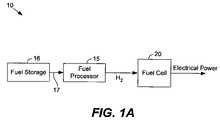
- FIG. 1Aillustrates a fuel cell system for producing electrical energy in accordance with one embodiment of the present invention.
- FIG. 1Billustrates schematic operation for the fuel cell system of FIG. 1A in accordance with a specific embodiment of the present invention.
- FIG. 2Ashows a simplified hydrogen fuel source storage device in accordance with one embodiment of the present invention.
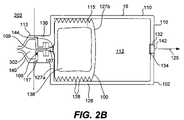
- FIG. 2Billustrates a cross sectional view of a hydrogen fuel source storage device in accordance with another embodiment of the present invention.
- FIG. 2Cillustrates a bellows configuration used in the storage device of FIG. 2B at its maximum volume.
- FIG. 2Dillustrates a front view of a fuel source storage device in accordance with one embodiment of the present invention.
- FIG. 2Eillustrates a front view of a storage device that is compatible with the storage device of FIG. 2D in accordance with another embodiment of the present invention.
- FIG. 2Fillustrates a front view of a storage device that is not compatible with the storage device of FIG. 2D in accordance with one embodiment of the present invention.
- FIG. 2Gillustrates a side view of the storage device of FIG. 2F .
- FIG. 3illustrates of a system for refilling a hydrogen fuel source storage device in accordance with one embodiment of the present invention.
- FIG. 4illustrates of a system for producing electrical energy for a portable electronics device in accordance with one embodiment of the present invention.
- FIG. 1Aillustrates a fuel cell system 10 for producing electrical energy in accordance with one embodiment of the present invention.
- Fuel cell system 10comprises storage device 16 , fuel processor 15 and fuel cell 20 .
- Storage device 16 and fuel processor 15provide hydrogen to fuel cell 20 .
- Storage device 16 and fuel processor 15collectively act as a “reformed” hydrogen supply that processes a hydrogen fuel source 17 to produce hydrogen.
- Hydrogen fuel source 17acts as a carrier for hydrogen and can be processed to separate hydrogen.
- Hydrogen fuel source 17may include any hydrogen bearing fuel stream, aliphatic fuel source or other hydrogen carrier such as ammonia.
- hydrocarbon fuel sources 17 suitable for use with the present inventioninclude methanol, ethanol, gasoline, propane, butane and natural gas, for example.
- hydrocarbon and ammonia productsmay also produce a suitable fuel source 17 .
- Liquid fuel sources 17offer high energy densities and the ability to be readily stored and shipped.
- Storage device 16stores fuel source 17 , and may comprise a refillable and/or disposable fuel cartridge.
- a refillable cartridgeoffers a user instant recharging.
- the cartridgeincludes a collapsible bladder within a hard plastic case. Storage device 16 is portable and described in further detail below.
- a separate fuel pumptypically controls fuel source 17 flow from storage device 16 . If system 10 is load following, then a control system meters fuel source 17 to deliver fuel source 17 to processor 15 at a flow rate determined by the required power level output of fuel cell 20 .
- Fuel processor 15processes the hydrocarbon fuel source 17 and outputs hydrogen.
- a hydrocarbon fuel processor 15heats and processes a hydrocarbon fuel source 17 in the presence of a catalyst to produce hydrogen.
- Fuel processor 15comprises a reformer, which is a catalytic device that converts a liquid or gaseous hydrocarbon fuel source 17 into hydrogen and carbon dioxide. As the term is used herein, reforming refers to the process of producing hydrogen from a fuel source.
- Fuel cell 20electrochemically converts hydrogen and oxygen to water, generating electrical energy and heat in the process. Ambient air commonly supplies oxygen for fuel cell 20 . A pure or direct oxygen source may also be used for oxygen supply. The water often forms as a vapor, depending on the temperature of fuel cell 20 components. The electrochemical reaction also produces carbon dioxide as a byproduct for many fuel cells.
- fuel cell 20is a low volume polymer electrolyte membrane (PEM) fuel cell suitable for use with portable applications such as consumer electronics.
- a polymer electrolyte membrane fuel cellcomprises a membrane electrode assembly 40 that carries out the electrical energy generating electrochemical reaction.
- the membrane electrode assembly 40includes a hydrogen catalyst, an oxygen catalyst and an ion conductive membrane that a) selectively conducts protons and b) electrically isolates the hydrogen catalyst from the oxygen catalyst.
- a hydrogen gas distribution layercontains the hydrogen catalyst and allows the diffusion of hydrogen therethrough.
- An oxygen gas distribution layercontains the oxygen catalyst and allows the diffusion of oxygen and hydrogen protons therethrough.
- the ion conductive membraneseparates the hydrogen and oxygen gas distribution layers.
- the anodecomprises the hydrogen gas distribution layer and hydrogen catalyst
- the cathodecomprises the oxygen gas distribution layer and oxygen catalyst.
- a PEM fuel celloften includes a fuel cell stack having a set of bi-polar plates.
- a membrane electrode assemblyis disposed between two bi-polar plates.
- Hydrogen distribution 43occurs via a channel field on one plate while oxygen distribution 45 occurs via a channel field on a second facing plate.
- a first channel fielddistributes hydrogen to the hydrogen gas distribution layer
- a second channel fielddistributes oxygen to the oxygen gas distribution layer.
- the term “bi-polar”refers electrically to a bi-polar plate (whether comprised of one plate or two plates) sandwiched between two membrane electrode assembly layers. In this case, the bi-polar plate acts as both a negative terminal for one adjacent membrane electrode assembly and a positive terminal for a second adjacent membrane electrode assembly arranged on the opposite face of the bi-polar plate.
- the anodeincludes the hydrogen gas distribution layer, hydrogen catalyst and bi-polar plate.
- the anodeacts as the negative electrode for fuel cell 20 and conducts electrons that are freed from hydrogen molecules so that they can be used externally, e.g., to power an external circuit.
- the bi-polar platesare connected in series to add the potential gained in each layer of the stack.
- the cathodeincludes the oxygen gas distribution layer, oxygen catalyst and bi-polar plate. The cathode represents the positive electrode for fuel cell 20 and conducts the electrons back from the external electrical circuit to the oxygen catalyst, where they can recombine with hydrogen ions and oxygen to form water.
- the hydrogen catalystseparates the hydrogen into protons and electrons.
- the ion conductive membraneblocks the electrons, and electrically isolates the chemical anode (hydrogen gas distribution layer and hydrogen catalyst) from the chemical cathode.
- the ion conductive membranealso selectively conducts positively charged ions. Electrically, the anode conducts electrons to a load (electrical energy is produced) or battery (energy is stored). Meanwhile, protons move through the ion conductive membrane.
- the protons and used electronssubsequently meet on the cathode side, and combine with oxygen to form water.
- the oxygen catalyst in the oxygen gas distribution layerfacilitates this reaction.
- One common oxygen catalystcomprises platinum powder very thinly coated onto a carbon paper or cloth. Many designs employ a rough and porous catalyst to increase surface area of the platinum exposed to the hydrogen and oxygen.
- fuel cell 20comprises a set of bi-polar plates formed from a single plate. Each plate includes channel fields on opposite faces of the plate. Since the electrical generation process in fuel cell 20 is exothermic, fuel cell 20 may implement a thermal management system to dissipate heat from the fuel cell. Further description of a fuel cell suitable for use with the present invention is included in commonly owned co-pending patent application entitled “Micro Fuel Cell Architecture” naming Ian Kaye as inventor and filed on Jun. 25, 2004, which is incorporated by reference for all purposes.
- fuel cell 20is phosphoric acid fuel cell that employs liquid phosphoric acid for ion exchange.
- Solid oxide fuel cellsemploy a hard, non-porous ceramic compound for ion exchange and may be suitable for use with the present invention.
- any fuel cell architecturemay benefit from the fuel storage improvements described herein.
- Other such fuel cell architecturesinclude direct methanol, alkaline and molten carbonate fuel cells.
- Fuel cell 20generates dc voltage that may be used in a wide variety of applications. For example, electrical energy generated by fuel cell 20 may be used to power a motor or light.
- the present inventionprovides “small” fuel cells that are configured to output less than 200 watts of power (net or total). Fuel cells of this size are commonly referred to as “micro fuel cells” and are well suited for use with portable electronics devices.
- fuel cell 20is configured to generate from about 1 milliwatt to about 200 watts. In another embodiment, fuel cell 20 generates from about 3 W to about 20 W.
- Fuel cell 20may also be a stand-alone fuel cell, which is a single unit that produces power as long as it has an a) oxygen and b) hydrogen or a hydrocarbon fuel supply. A stand-alone fuel cell 20 that outputs from about 40 W to about 100 W is well suited for use in a laptop computer.
- fuel processor 15is a steam reformer that only needs steam and the fuel source 17 to produce hydrogen.
- reformers suitable for use in fuel cell system 10include steam reformers, auto thermal reformers (ATR) or catalytic partial oxidizers (CPOX).
- ATR and CPOX reformersmix air with the fuel and steam mix.
- ATR and CPOX systemsreform fuels such as methanol, diesel, regular unleaded gasoline and other hydrocarbons.
- storage device 16provides methanol 17 to fuel processor 15 , which reforms the methanol at about 250° C. or less and allows fuel cell system 10 use in applications where temperature is to be minimized. Further description of a fuel processor suitable for use with the present invention is included in commonly owned co-pending patent application entitled “Efficient Micro Fuel Cell Systems and Methods” naming Ian Kaye as inventor and filed on Jun. 25, 2004, which is incorporated by reference for all purposes.
- FIG. 1Billustrates schematic operation for fuel cell system 10 in accordance with a specific embodiment of the present invention.
- fuel cell system 10comprises hydrogen fuel source storage device 16 , hydrogen fuel source 17 , fuel processor 15 , fuel cell 20 , multiple pumps 21 and fans 35 , fuel lines and gas lines, and one or more valves 23 .
- Fuel container 16stores methanol as a hydrogen fuel source 17 .
- An outlet 26 of fuel container 16provides methanol 17 into hydrogen fuel source line 25 .
- line 25divides into two lines: a first line 27 that transports methanol 17 to a burner 30 for fuel processor 15 and a second line 29 that transports methanol 17 to reformer 32 in fuel processor 15 .
- Lines 25 , 27 and 29may comprise plastic tubing, for example.
- Separate pumps 21 a and 21 bare provided for lines 27 and 29 , respectively, to pressurize the lines and transmit the fuel source at independent rates if desired.
- a model P625 pump as provided by Instech of Plymouth Meeting, PAis suitable to transmit liquid methanol for system 10 is suitable in this embodiment.
- a flow sensor or valve 23 situated on line 29 between storage device 16 and fuel processor 15detects and communicates the amount of methanol 17 transfer between storage device 16 and reformer 32 .
- pump 21 bregulates methanol 17 provision from storage device 16 to reformer 32 .
- Fan 35 adelivers oxygen and air from the ambient room through line 31 to regenerator 36 of fuel processor 15 .
- Fan 35 bdelivers oxygen and air from the ambient room through line 33 to regenerator 36 of fuel processor 15 .
- a model AD2005DX-K70 fan as provided by Adda USA of Californiais suitable to transmit oxygen and air for fuel cell system 10 .
- a fan 37blows cooling air over fuel cell 20 and its heat transfer appendages 46 .
- Fuel processor 15receives methanol 17 from storage device 16 and outputs hydrogen.
- Fuel processor 15comprises burner 30 , reformer 32 and boiler 34 .
- Burner 30includes an inlet that receives methanol 17 from line 27 and a catalyst that generates heat with methanol presence.
- Boiler 34includes an inlet that receives methanol 17 from line 29 . The structure of boiler 34 permits heat produced in burner 30 to heat methanol 17 in boiler 34 before reformer 32 receives the methanol 17 .
- Boiler 34includes an outlet that provides heated methanol 17 to reformer 32 .
- Reformer 32includes an inlet that receives heated methanol 17 from boiler 34 .
- a catalyst in reformer 32reacts with the methanol 17 and produces hydrogen and carbon dioxide.
- fuel processor 15also includes a preferential oxidizer that intercepts reformer 32 hydrogen exhaust and decreases the amount of carbon monoxide in the exhaust.
- the preferential oxidizeremploys oxygen from an air inlet to the preferential oxidizer and a catalyst, such as ruthenium or platinum, that is preferential to carbon monoxide over carbon dioxide.
- Fuel processormay also include a dewar 36 that pre-heats air before the air enters burner 30 .
- the dewaralso reduces heat loss from fuel cell 20 by heating the incoming air before it escapes fuel processor 15 .
- dewaracts as a regenerator that uses waist heat in fuel processor 15 to increase thermal management and thermal efficiency of the fuel processor.
- waist heat from burner 30may be used to pre-heat incoming air provided to burner 30 to reduce heat transfer to the air in the burner so more heat transfers to reformer 32 .
- Line 39transports hydrogen from fuel processor 15 to fuel cell 20 .
- Gaseous delivery lines 31 , 33 and 39may comprise plastic tubing, for example.
- a hydrogen flow sensor(not shown) may also be added on line 39 to detect and communicate the amount of hydrogen being delivered to fuel cell 20 .
- fuel processor 15regulates hydrogen gas provision to fuel cell 20 .
- Fuel cell 20includes a hydrogen inlet port that receives hydrogen from line 39 and delivers it to a hydrogen intake manifold for delivery to one or more bi-polar plates and their hydrogen distribution channels 43 .
- An oxygen inlet port of fuel cell 20receives oxygen from line 33 and delivers it to an oxygen intake manifold for delivery to one or more bi-polar plates and their oxygen distribution channels 45 .
- An anode exhaust manifoldcollects gases from the hydrogen distribution channels 43 and delivers them to an anode exhaust port, which outlets the exhaust gases into the ambient room.
- a cathode exhaust manifoldcollects gases from the oxygen distribution channels 45 and delivers them to a cathode exhaust port.
- system 10may also include other elements such as electronic controls, additional pumps and valves, added system sensors, manifolds, heat exchangers and electrical interconnects useful for carrying out functionality of a fuel cell system 10 that are known to one of skill in the art and omitted herein for sake of brevity.
- FIG. 2Ashows a simplified hydrogen fuel source storage device 16 in accordance with one embodiment of the present invention.
- FIG. 2Billustrates a cross sectional view of a storage device 16 in accordance with another embodiment of the present invention.
- hydrogen fuel source storage device 16comprises a bladder 100 , housing 102 , connector 104 and memory 106 .
- Bladder 100contains the hydrogen fuel source 17 and conforms to the volume of the hydrogen fuel source in the bladder.
- bladder 100comprises a compliant structure that mechanically assumes a volume 115 according to a volume of liquid stored therein.
- the volume 115is formed by compliant walls 101 of bladder 100 , which expand and/or open when fluid is added to bladder 100 , and contract and/or collapse when fluid is removed according to the negative pressure developed upon fluid removal.
- bladder 100includes a sac that changes size and shape with the volume of liquid contained therein.
- Plastic, rubber, latex or a metal such as nickelare suitable materials for use with the walls 101 of bladder 100 . In this case, the walls 101 are compliant and change size with a changing liquid volume 115 .
- Plastic walls 101may also comprise a fire retardant plastic material.
- a fire retardant plastic material for walls 101is NFPA-701-99 Test 1 Polyethelyne as provided by Plasticare of Orange Park, Fla.
- bladder 100comprises a fixed cylinder and a piston that is pushed by a spring and moves in the cylinder to displace used fuel.
- Bladder 100is characterized by a maximum volume 119 when the bladder fully expands.
- FIG. 2Cillustrates the bellows configuration used in the storage device of FIG. 2B at its maximum volume 119 .
- maximum volumes for bladder 100range from about 20 milliliters to about 4 liters. Maximum volumes from about 20 milliliters to about 400 milliliters are suitable for many portable electronics applications. A maximum volume for bladder 100 of 200 milliliters is suitable for laptop computer usage. Some extended run time systems may rely on storage devices 16 having 80 liters of maximum volume. The maximum volume for bladder 100 may differ from the fuel source capacity of storage device 16 .
- storage device 16comprises multiple bladders 100 that each contributes a maximum volume that cumulatively add to a total fuel source capacity for storage device 16 .
- a spare storage device 16 intended for electronics power back-upmay contain two bladders 100 each including 300 milliliters of hydrogen fuel source 17 .
- bladder 100 and storage device 16may contain other hydrocarbon fuel sources such as those listed above.
- bladder 100may contain a fuel mixture.
- the fuel processor 15 fed by storage device 16comprises a steam reformer
- bladder 100may contain a fuel mixture of a hydrocarbon fuel source and water.
- Hydrocarbon fuel source/water fuel mixturesare often represented as a percentage fuel source in water.
- hydrogen fuel source 17comprises methanol or ethanol concentrations in water in the range of 1%-99.9%.
- hydrogen fuel source 17may comprise 100% methanol or ethanol.
- Other liquid fuelssuch as butane, propane, gasoline, military grade “JP8” etc. may also be contained in storage device 16 with concentrations in water from 5-100%.
- bladder 100stores 67% methanol by volume.
- Housing 102provides mechanical protection for bladder 100 and any other components of storage device 16 included within housing 102 .
- Housing 102comprises a set of rigid walls 110 that contain bladder 100 and other internal components of storage device 16 .
- all components of storage device 16are contained within housing 102 save any portions of connector 104 that protrude out of the housing for interface with mating connector 140 .
- connector 104is recessed within housing 102 and housing 102 provides an outer shell that substantially defines outer bounds and shape of storage device 16 .
- Walls 110collectively form an outer case or shell for storage device 16 that mechanically separates components internal to housing 102 from the external environment. Walls 110 also collectively form an interior cavity 112 .
- Interior cavity 112is a space within storage device that contains bladder 100 . As described below, interior cavity 112 may comprises multiple compartments, each of which include a separate bladder 100 .
- Rigid walls 110may comprise a suitably stiff material such as a plastic, metal (e.g., aluminum), polycarbonate, polypropelene, carbon fiber matrix, carbon composite material, etc. Rigid walls 110 may also be formed from a fire retardant material such as a fire retardant plastic material.
- a fire retardant materialsuch as a fire retardant plastic material.
- One suitable fire retardant plastic material for walls 110is 8-12% weight, JLS-MC mixed with PA66 Polyamide as provided by JLS Chemical of Pomona, Calif.
- Rigid walls 110may be designed according to criteria for construction of thin walled pressure vessels. Such criteria are known to those of skill in the art. In this case, walls 110 and housing 102 may be designed to withstand a maximum pressure within internal cavity 112 or for bladder 100 .
- Housing 102may include an elliptical (including circular) shape, a rectangular shape with chamfered corners, or other substantially consistent profile or shape in a given direction.
- FIGS. 2D-2Fillustrate some suitable housing 102 shapes.
- housing 102includes a substantially consistent shape in a direction 125 that extends normally away from a tube 107 in connector 104 .
- housing 102comprises a transparent section or clear window to allow for visual fuel gauging.
- housing 102is integrally formed to prevent disassembly of housing 102 .
- walls 110may be permanently bonded or extruded from a common material in one piece such that access into housing 102 is only gained through destruction of walls 110 and housing 102 .
- Connector 104interfaces with a mating connector 140 (see FIG. 2B ) included in an external device. Together, connector 104 and mating connector 140 permit transfer of fuel source 17 between bladder 100 and the external device.
- mating connector 140is included in fuel processor 15 or a device that includes fuel processor 15
- connector 104 and mating connector 140interface to permit transfer of fuel source 17 from storage device 16 to the fuel processor 15 .
- mating connector 140is included in a hydrogen fuel source refiller
- connector 104 and mating connector 140interface to permit transfer of fuel source 17 from the refiner to storage device 16 .
- Interface between connector 104 and mating connector 140may comprise any relationship and mating structures that permit fluid communication between the two connectors.
- Connector 104 and/or mating connector 140may also include mechanical coupling to secure the interface, such as latching elements that bind connector 104 and mating connector 140 together until physically released.
- Connector 104 and mating connector 140may also each include electrical leads that contact when the connectors are attached to enable electrical and digital communication.
- Connector 104 and mating connector 140each comprise a geometry that at least partially matches geometry of the other. Exemplary connector 104 and mating connector 140 geometries are described below with respect to FIGS. 2D-2G .
- connector 104incorporates a quick disconnect that permits storage device 16 to be readily removed by pulling on housing 102 . This separates connector 104 and mating connector 140 and detaches any electrical links and plumbing responsible for fluid communication between storage device 16 and the device including mating connector 140 . A second storage device 16 with a quick disconnect connector 104 may then be readily inserted back into mating connector 140 . The quick disconnect thus allows rapid replacement of storage device 16 with another storage device 16 when fuel source volume levels are low.
- the quick disconnect connector 104includes one port or multiple ports according to the plumbing needs of storage device 16 (e.g., fuel provision and a scrubbing bed).
- a quick disconnect connector 104may also include other features to control removal requirements such as two handed operation or a high force actuator.
- quick disconnect connectorsare available from a variety of vendors.
- One suitable quick disconnect connectoris model number QDC101 as provided by Beswick of Greenland, N.H.
- storage device 16may also include a hot swappable capability that improves quick disconnect usage for connector 104 and mating connector 140 .
- Connector 104 and mating connector 140may provide an automatic shutoff capability when device 16 is removed from system 202 . In this case, each only open when connected to the other and when device 16 interfaces with device 202 .
- device 16comprises a small sponge or swab located on or near connector 104 to collect any fuel leakage during device connection or disconnect.
- one of connector 104 and mating connector 140includes a ‘male’ designation and configuration while the other includes a ‘female’ designation and configuration.
- the male configurationincludes portions of the connector that protrude, such as one or more pins or electrical leads.
- the female configurationincludes portions of the connector that receive the male portions, such as holes electrically lined to receive the male portion and facilitate electrical communication.
- connector 104 on storage device 16includes a female configuration that recesses within housing 102 . Since it is recessed, connector 104 cannot be knocked off during rough handling.
- Mating connector 140is configured on a side portion of an OEM device (i.e., a laptop computer). As will be described in further detail below, mating connector 140 is also included in refilling hardware that refills storage device 16 with fuel source 17 .
- Memory 106stores information relevant to usage of storage device 16 .
- Memory 106may comprise a mechanical, electrical and/or digital mechanism for information storage.
- memory 106comprises a digital memory source that permits an external controller to read and write from the digital memory.
- memory 106includes a mechanical device.
- One suitable mechanical devicecomprises “break-off” pins 158 (see FIG. 2D ).
- Other forms of mechanical memory 106may comprise discs or rods which are removed or otherwise manipulated every time a storage device 16 is refilled.
- memory 106is external to housing 102 and comprises a visible identification tag that uniquely identifies storage device 16 .
- Various types of external identification tagsare known in the art and may be used with this invention. Two examples of identification identifier tags include magnetic recording devices and optical bar codes.
- storage device 16is considered “smart” since memory 106 stores information related to the performance, status and abilities of storage device 16 .
- a digital memoryallows an external controller or logic to read and write information relevant to usage of the storage device to memory 106 . Reading from a digital memory 106 allows reception and assessment of information in memory 106 to improve usage of storage device 16 .
- a computer that receives storage device 16may inform a user that the storage device 16 is empty or how much fuel is left (or how much time on the system is available based on its power consumption and the amount of fuel remaining).
- Writing to a digital memory 106allows information in memory 106 to be updated according to storage device 16 usage. Thus, if a user nearly depletes fuel source 17 in storage device 16 while powering a computer, the next user may be informed after the first computer writes an updated amount of fuel source 17 remaining in storage device 16 into memory 106 .
- Storage device 16 specifications stored in memory 106generally do not change with device 16 usage and may comprise a) a fuel type stored in the storage device when device 16 is dedicated to service a particular hydrocarbon fuel source 17 , b) a model number for storage device 16 , c) an identification signature for the manufacturer of storage device 16 , d) manufacture date, and e) a volume capacity for bladder 100 or storage device 16 .
- the model number of device 16allows it to be distinguished from a number of similar devices.
- Transient information stored in memory 106 that changes according to the status and usage of storage device 16may comprise a) hydrogen fuel mixture information, b) a number of refills provided to storage device 16 when device 16 is configured for re-usable service, c) the last refill date, d) the refilling service provider that refilled storage device 16 when the device is configured for re-usable service, e) usage history according to a storage device identification, and f) a current volume for the storage device.
- storage device 16comprises a bladder 100 with a collapsible bellows configuration 126 , housing 102 , connector 104 , memory 106 , air vent 132 , filter 134 , pressure relief valve 136 , fire retardant foam 138 , mechanical shield 142 , and fuel source filter 144 .
- Connector 104comprises tube 107 and female bay 117 .
- Storage device 16connects to a laptop computer 202 , which includes mating connector 140 .
- Mating connector 140comprises tube 109 , reserve volume 302 and male housing 113 .
- Mating connector 140interfaces with connector 104 to permit transfer of hydrogen fuel source 17 from storage device 16 to laptop computer 202 .
- storage device 16resembles a battery-sized cartridge including a female connector 104 that receives a male mating connector 140 .
- Male housing 113 of mating connector 140fits snugly into a female bay 117 of connector 104 (see FIG. 2G for side view of a bay 117 ). The fit provides mechanical support for the interface between mating connector 140 and connector 104 .
- Distal end of tube 107 in storage device 16 and a distal end of tube 109 in mating connector 140align when connector 104 and mating connector 140 join.
- tube 109comprises a pointed end that pierces into tube 107 and tube 109 comprises a diameter that snugly fits into tube 107 when connector 104 and mating connector 140 are attached.
- a pump run by a fuel cell system 10 within laptop computer 202draws fluid from bladder 100 into the fuel cell system 10 . More specifically, fuel source 17 travels from bladder 100 , through tube 107 in connector 104 , into and through tube 109 in mating connector 140 , and through tube 109 in laptop computer 202 to a fuel processor 15 included therein.
- Connector 104 and mating connector 140may also include electrical connectivity for digital communication between memory 106 and a processor or controller (see FIG. 4 ) on laptop computer 202 .
- FIG. 2Fillustrates female electrical slots 155 on connector 104 b .
- a mating connector 140 for connector 104 bthen includes male leads (not shown) that fit into slots 155 for electrical communication between laptop computer 202 and storage device 16 .
- bladder 100comprises a collapsible bellows design 126 .
- One end 127 a of bellows 126attaches and opens to tube 107 , while the opposite end 127 b is free to move in direction 125 .
- free end 127 bmoves in direction 125 and bellows 126 expands and increases in volume.
- free end 127 b and bladder 100thus compresses towards the location where fuel source 17 is outlet and where negative pressure is created to contract or collapse bellows 126 (tube 107 and connector 104 in this case).
- FIG. 2Cillustrates a bellows configuration 126 at its maximum volume.
- bladder 100is less than half full of fuel source 17 and assumes less than half the space in internal cavity 112 .
- Bellows 126comprises collapsible rings 128 that fold as bellows 126 expands (the angle of each ring 128 opens) and as bellows 126 collapse (the angle of each ring 128 closes).
- Bellows 126may comprise plastic or Nickel, for example.
- Bellows 126may be custom molded or electroformed. Similarly designed bellows are used to protect tubular warp in machine tools, for example.
- Servometer Corp. of New Jerseyprovides several suitable commercially available nickel bellows.
- Storage device 16includes an air vent 132 in housing 102 that allows air to enter and exit in internal cavity 112 within housing 102 as bladder 100 changes in volume.
- Air vent 132comprises one or more holes or apertures in a wall 110 of housing 102 .
- bladder 100collapses and creates a negative pressure in internal cavity 112 outside of bladder 100 . Based on this negative pressure caused by a decreasing volume of bladder 100 (or increasing volume of internal cavity 112 outside bladder 100 ), air enters through air vent 132 into internal cavity 112 and displaces the decreasing volume of bladder 100 . This prevents the pressure of fuel source 17 in bladder 100 from decreasing and affecting the ability of storage device 16 to provide fuel source 17 at a substantially constant pressure.
- bladder 100When filling storage device 16 , positive pressure caused by an increasing volume of fuel source 17 and bladder 100 causes air to exit through air vent 132 . Since walls of bladder 100 separate fuel source 17 within bladder 100 from air in internal cavity 112 , air in cavity 112 does not enter bladder 100 or mix with fuel source 17 .
- a filter 134spans the cross section of air vent 132 and intercepts air passing through air vent 132 .
- filter 134comprises a hydrophobic and gas permeable filter that prevents foreign materials from entering storage device 16 .
- Materials blocked by filter 134may include liquids and particles such as undesirable oils and abrasives that may affect storage device 16 performance.
- the hydrophobic filteralso prevents fuel source 17 from escaping housing 102 in the event that bladder 100 develops a leak.
- Filter 134may comprise micro porous Teflon or another micro porous material such as Teflon coated paper.
- a sintered metal filterfor example one with a 3 micron pore size, may also be used.
- One suitable filter 134includes micro porous “Gore Tex” Teflon as provided by WL Gore Associates of Elkton, Md.
- Mechanical shield 142spans and covers air vent 132 and prevents foreign bodies from entering housing 102 through air vent 132 and damaging bladder 100 .
- air vent 132is recessed into a wall 110 such that mechanical shield 142 is flush with the outer surface of housing 102 .
- filter 134is located internal to shield 142 such that shield 142 mechanically protects filter 134 .
- mechanical shield 142includes a flame suppressor or a suitable means of flame suppression. The mechanical shield 142 then prevents flame propagation into or out from interior cavity 112 .
- One suitable mechanical shield 142includes cut to size 180 ⁇ 180 mesh stainless steel screen as provided by McNichols of Tampa, Fla.
- Pressure relief valve 136limits pressure in storage device 16 . More specifically, pressure relief valve 136 releases fuel source 17 from bladder 100 when the pressure within bladder 100 reaches a threshold pressure.
- the threshold pressurerefers to a pressure for bladder 100 that represents the upper limit of operational pressure for fuel source 17 use in storage device 16 . Threshold pressures from about 5 psig to about 25 psig are suitable for some fuel sources 17 and storage devices 16 . A threshold pressure of about 15 psig is suitable in many cases. Other suitable threshold pressures may relate to the boiling point of the fuel source 17 , which ranges from about 2 Atm to about 10 Atm. Thus, if temperature for storage device 16 rises above the boiling point of fuel source 17 , the threshold pressure is reached and pressure relief valve 136 releases fuel source 17 from bladder 100 .
- the partial pressure of fuel source 17 in bladder 100is less than the threshold pressure and pressure relief valve 136 is not used. In the event that pressure of fuel source 17 in bladder 100 rises above the threshold pressure, pressure relief valve 136 releases fuel source 17 from bladder 100 , thereby limiting the pressure within bladder 100 .
- pressure relief valve 136comprises a sprung diaphragm mechanism.
- the sprung diaphragmincludes a diaphragm and a spring that attaches to the diaphragm. Pressure in bladder 100 pushes the diaphragm outward against the spring force. At the threshold pressure, the diaphragm opens a port—a small hole that opens outside of housing 102 —to permit the release of fuel source 17 from bladder 100 . Spring selection permits a designer to control the threshold pressure at which the port opens and fuel source 17 escapes.
- pressure relief valve 136comprises a burst disk mechanism that includes a thin diaphragm. The diaphragm breaks outward when pressure in bladder 100 rises above the threshold pressure. The diaphragm break and the resultant opening releases fuel source 17 from bladder 100 .
- the port or openingmay be configured to direct venting fuel vapors away from storage device 16 and into a ventilated area when installed in an electronics or OEM device.
- a fuel source filter 144intercepts fuel source 17 as it leaves bladder 100 and before it leaves connector 104 . As shown, filter 144 spans an entrance to tube 107 from bladder 100 . Fuel source filter 144 removes any contaminants or chemicals added to fuel source 17 for storage in bladder 100 and device 16 .
- fuel source 17comprises an odorant 150 , a bitterant 152 and/or a colorant 154 mixed therein. If fuel source 17 comprises an odorless liquid, odorant 150 provides olfactory stimulus to inform a person that fuel source 17 has escaped bladder 100 and storage device 16 via a path other than through tube 107 and filter 144 .
- Two suitable odorants 150includes trimethyl amine at 1-10 ppm in methanol and ethyl mercaptan at 1-7 ppm weight in methanol.
- Fuel source filter 144removes odorant 150 from fuel source 17 when the fuel source leaves bladder 100 through tube 107 .
- colorant 154provides visual stimulus to inform a person that fuel source 17 has leaked or escaped from bladder 100 via a path other than through tube 107 and filter 144 .
- Suitable colorants 154include acid blue 9 at 1 ppm, table 5-4 food dye, and bright green/blue erioglaicine disodium salt as provided by Dudley Chemical Corp of Lakewood, N.J.
- Fuel source filter 144removes colorant 154 from hydrogen fuel source 17 when the fuel source leaves bladder 100 through tube 107 .
- a bitterant 152may be added to provide taste stimulus that informs a person that fuel source 17 has escaped bladder 100 via a path other than through tube 107 and filter 144 .
- One suitable bitterant 152includes Denatonium Benzoate at 1-50 ppm (20-50 ppm is adversely bitter) as provided by Bitrex of Edinburgh, UK.
- Fuel source filter 144removes bitterant 152 from hydrogen fuel source 17 when fuel source 17 leaves bladder 100 through tube 107 .
- One suitable filter 144 for removing odorant 150 , bitterant 152 and/or colorant 154includes an ultra-pure polyethersulfone membrane.
- Another suitable filter 144 for removing odorant 150 , bitterant 152 and/or colorant 154 from fuel source 17includes 0 . 1 Advantage PS C-7012 filter as provided by Parker Hanafin Corp.
- a fire retardant foam 138is disposed in bladder 100 .
- Foam 138is compliant and conforms in size to the size of bladder 100 . Thus, as bladder 100 collapses, foam 138 compresses. In one embodiment, foam 138 acts as a wicking foam that directs some flame behavior in storage device 16 .
- One suitable foam 138is polyurethane mil Spec Mil-B-83054 as provided by Foamex of Lindwood, Pa.
- memory 106comprises a wireless identification (ID) tag.
- IDwireless identification
- the external deviceincludes an interrogator that probes memory 106 via wireless communication when storage device 16 is in range of the interrogator.
- the interrogatormay include any hardware for performing this function such as a computer, transceiver and interrogator antenna. Coupling between the interrogator and storage device 16 may occur via radio frequency (RF) or microwave frequency radiation.
- RFradio frequency
- storage device 16When probed by the interrogator, storage device 16 replies with its identification (as stored in a digital or electrical memory 106 ) and any other information stored in memory 106 , such as the status of any sensors used in storage device 16 to monitor health of the device and sensors that detect the volume of fuel source in bladder 100 .
- the storage device 16 identificationprovides a means for automated logging of data corresponding to the status of storage device 16 .
- the identificationalso facilitates inventory logging of information for numerous storage devices 16 .
- the interrogatorprovides power to storage device 16 .
- the poweris transmitted by RF waves, for example, and received by a rectifier in storage device 16 that rectifies the signal, thereby providing sufficient DC power to operate any circuitry of storage device 16 .
- a transponder included in storage device 16responds to a wireless stimulus.
- the transpondertransmits signals when actuated by a signal from an external interrogator.
- the transponderincludes an amplifier for increasing the strength of a received incident signal, a modulator for modifying the signal with information stored by memory 106 , and an antenna or antennas for receiving and transmitting signals.
- Wireless ID tagsare commercially well known and there exists numerous manufacturers that currently offer a wide selection of RFID tags. These tags are either passive (typically operating near 125 khz) or active (often operating near 2.45 GHz). Major manufacturers include Texas Instruments of Dallas, Tex. and Motorola of San Jose, Calif. or Alien Technologies of San Jose, Calif. Products are available for inventory control, product labeling, etc.
- storage device 16may use a commercial RFID tag, such as a 125-khz tag supplied by Texas Instruments of Dallas, Tex., which includes a microchip for memory 106 and inductor for wireless communication.
- Storage device 16may also comprise a sensor that monitors a condition related to the health or functioning of storage device 16 .
- the sensorcomprises a wire 156 that runs about an inside surface of housing 102 or is formed within a wall 110 housing 102 (see FIG. 2C ).
- An electrical state or performance of wire 156provides an indication of the health of housing 102 .
- Mechanical damage, cracking or structural compromise of housing 102affects wire 156 —mechanically and electrically. More specifically, when wire 156 breaks, stretches or loses contact due to mechanical changes housing 102 , an electrical signal sent through wire 156 changes. The according change may be read and assessed. Thus, a break in wire 156 may be read by non-transmittance of a signal.
- Changes in electrical resistance of wire 156may also provide an indication of health.
- the sensorrelies on external (e.g., RFID) probing to assess the state of wire 156 and health of housing 102 .
- the interrogatorpowers memory 106 to test the resistance of wire 156 .
- the RFID memory 106then responds with a signal indicative of the status of wire 156 .
- the sensoris shown as a single wire 156 , it is understood that more complex designs may comprise filament networks that extend two dimensionally throughout housing 102 . Each filament may then be probed for its electrical status, e.g., resistance to provide a meshed status check of integrity and health of housing 102 and storage device 16 .
- FIG. 2Dillustrates a front view of fuel source storage device 16 a in accordance with one embodiment of the present invention.
- FIG. 2Eillustrates a front view of a storage device 16 b that is partially compatible with storage device 16 a .
- FIG. 2Fillustrates a front view of a storage device 16 c that is not compatible with storage device 16 a .
- FIG. 2Gillustrates a side view of a storage device 16 c.
- Connector 104 and/or mating connector 140may include a “keyed” configuration that provides interface selectivity.
- connector 104may comprise a configuration unique to a particular hydrogen fuel source (e.g., methanol).
- mating connector 140offers an exclusive interface that only receives a connector 104 for a methanol based storage device 16 .
- This keying systemprevents the wrong fuel type from being installed in a device that cannot accept that fuel, e.g., gasoline bums at a higher temperature and may not be suitable for use in all methanol fuel processors.
- This keying systemalso prevents storage device 16 from being refilled with the wrong hydrogen fuel source 17 .
- storage device 16 a of FIG. 2Dincludes a circular connector 104 a that interfaces with a circular mating connector (not shown).
- storage device 16 b of FIG. 2Eincludes a circular connector 104 a of the same dimensions that interfaces with the same circular mating connector as that employed for connector 104 a .
- the storage device 16 c of FIG. 2Fincludes a rectangular connector 104 b that would not interface with the same circular mating connector.
- Circular connectors 104 amay be used for methanol fuel mixtures of different blends for example, while rectangular connector 104 b is used for ethanol.
- connector 104may change slightly while mating connector 140 remains constant.
- a common mating connector 140may receive different storage devices 16 that share a connector 104 a configuration.
- the different storage devices 16may be produced by different manufacturers and may include varying volumes or other storage device 16 features. This permits competition for the provision of storage devices 16 but standardization of their interface.
- an electronics device manufacturersuch as Dell specifies a custom mating connector 140 configuration (e.g., a circular configuration used in their laptop computers and other electronics devices). All storage devices 16 that service these electronics devices must then include a connector 104 that matches Dell's custom mating connector 140 configuration.
- the electronics device manufacturermay then control who manufacturers storage devices 16 and connectors 104 for use with their electronics devices. Keyed connectors 104 a for one electronics device manufacturer may also be designed to not fit a mating connector 140 for another computer manufacturer, e.g., Apple employs a rectangular configuration 104 b.
- Custom connector 104 and mating connector 140 configurationsmay vary based on geometry, dimensions, depth and size for example.
- a connector 104 or mating connector 140may also include one or more features 149 that distinguish a custom connector or mating connector. As shown in FIG. 2E , feature 149 is a tab that extends into the female bay 117 of connector and mechanically distinguishes storage device 16 b from storage device 16 a.
- Connector 104 /mating connector 140 configuration selectivitymay also be implemented to distinguish developing technology in fuel cell system 10 or storage device 16 .
- mating connector 140By changing mating connector 140 to receive only certain connectors 104 , the present invention permits continuing development of fuel cell system 10 or storage device 16 and ensures rejection of previous storage device 16 models that are no longer suitable.
- storage device 16 bmay represent a newer version of storage device 16 a that is mechanically distinguished by feature 149 .
- An electronics device that receives storage devices 16may include a mating connector 140 that mechanically rejects storage device 16 a based omission of feature 149 .
- Memory 106may also be digitally read to indicate incompatibility.
- FIGS. 2D-2Fmay also be implemented for particular fuel source 17 types.
- storage device 16 a and connector 104 amay designate a methanol fuel mixture “A%”
- storage device 16 b and feature 149designate a methanol fuel mixture “B%”
- storage device 16 c and connector 104 bdesignates an ethanol fuel mixture.
- Storage devices 16 aalso comprise “break-off” pins 158 that form a mechanical memory 106 .
- Pins 158indicate the number of refills for each storage device 16 . Each time storage device 16 is refilled, the refiner breaks a pin 158 . When all the pins have been removed, a mating connector to connector 104 will not accept storage device 16 .
- Pins 158may comprise plastic and be molded into the cartridge housing 102 or to connector 104 .
- storage device 16is intended for disposable use. In this case, a user purchases a storage device 16 with a full complement of methanol and disposes of storage device 16 after it is emptied. In another embodiment, storage device 16 is intended for reusable use. A reusable storage device 16 provides less waste. In this case, storage device 16 is refilled by a hydrogen fuel source refiller.
- FIG. 3Illustrates a system 160 for providing a refillable hydrogen fuel source storage device 16 in accordance with one embodiment of the present invention.
- System 160comprises storage device 16 and a hydrogen fuel source refiner 162 .
- Hydrogen fuel source refiller 160includes mating connector 140 and is configured to provide hydrogen fuel source 17 to storage device 16 when the connector 104 is coupled to mating connector 140 .
- Connector 104 and mating connector 140interface to permit transfer of fuel source 17 from refiner 160 to storage device 16 .
- Refiller 160comprises a fuel reserve tank 164 that stores hydrogen fuel source 17 . Tank is suitably size to refuel numerous storage devices 16 .
- a pump 166receives control signals from a refiner controller 168 that controls functioning of refiner 160 based on stored commands in refiner memory 170 .
- Refiller memory 170may also include a database that stores information for each storage device 16 serviced by refiner 160 .
- a line 172transports fuel source 17 from tank 164 to storage device 16 . More specifically, pump 166 moves fluid fuel source 17 from tank 164 through tube 109 in mating connector 140 , into and through tube 107 in connector 104 , and into bladder 100 for storage therein.
- refiner 160is shown refilling a single storage device 16 , it is understood that refiller 160 may comprise multiple “bays” that each include a mating connector 140 and plumbing to refill a single storage device 16 .
- Refiller 160may also include multiple tanks 164 that provided different fuel sources 17 , such as different fuel sources (e.g., methanol or ethanol) or different fuel mixtures.
- Controller 168also communicates with memory 106 via line 174 , which travels from controller 168 , through electrical connectivity provided by connector 104 and mating connector 140 and to memory 106 . Controller 168 may also communicate with memory 106 via wireless means as described above if controller 168 and memory 106 both include such capability.
- Refiller 160includes an interrogator 176 to communicate wirelessly with a storage device 16 . Interrogator 176 comprises a transceiver and antenna based on the communication frequency employed.
- Controller 168reads from and writes to memory 106 . Controller 168 may read and store the usage history of a digital memory 106 . When storage device 16 includes a mechanical memory such as the break-off pins 158 described above, refiner 162 checks if there are any pins 158 remaining (either mechanically or electronically). If all the pins have been removed, refiner 162 does not accept storage device 16 . Controller 168 may also check the status of any sensors on storage device 16 used to monitor health of the device 16 , such as an RDIF sensor that detects housing integrity. This helps a re-filling services provider determine if storage device 16 can be simply be refilled, or if it needs to refurbished as well.
- RDIF sensorthat detects housing integrity
- refiner 162is thus configured to detect a defect in storage device 16 and not transfer hydrogen fuel source 17 to storage device 16 when a predetermined memory element is present.
- Memory elementsmay include use of a pressure relief valve or information related to the status of any sensors on storage device 16 .
- Controller 168may also write into memory 106 information such as: the hydrogen fuel mixture information stored therein, an updated number of refills provided to storage device 16 , the refill date, the refilling service provider, and a volume for the storage device.
- storage device 16includes a mechanical memory such as the break-off pins 158 described above, refiner 162 breaks a pin 158 upon refill completion.
- Refillable system 160allows distribution of the hydrogen fuel source 17 to be handled flexibly.
- One approachis to distribute refillable storage devices 16 similar to the distribution of batteries.
- a consumerpurchases a desired storage device 16 at a retail outlet, such as a department store, super market, airport kiosk or drug store etc.
- Storage device 16 selectionmay vary based on fuel source 17 capacity, fuel source 17 type or other features such as connectivity and smart features.
- Spent storage devices 16may be dropped off at the any of the above locations for reuse, and shipped to a refilling services provider for refurbishment and refill.
- refiner 162may also rejuvenate or check for replacement of the cleaning system.
- refiner 162rejuvenates the cleaning system by forcing hydrogen through the bed (e.g., using hydrogen in tank 164 ).
- the scrubbing bed filter 220may also be replaced with a new bed when the storage device 16 is refilled.
- Refilling system 160allows a hydrogen fuel source 17 refilling provider to control refilling of storage devices 16 .
- Connectors 104 that require specific parts on mating connector 140 to complete interface and permit fluid transfer into storage device 16also prevent free tampering and addition of fluids to storage device 16 .
- Refilling system 160also provides a business model for distribution of storage devices 16 .
- Refilling system 160also permits the hydrogen fuel source 17 refilling provider to certify fuel blends, monitor the number of refills for a particular storage device 16 , and validate storage device 16 for consumer or manufacturer confidence.
- FIG. 4shows a schematic illustration of a system 200 for producing electrical energy for a portable electronics device in accordance with one embodiment of the present invention.
- System 200comprises fuel processor 15 and fuel cell 20 included within an electronics device 202 and a hydrogen fuel source storage device 16 coupled to electronics device 202 via connector 104 and mating connector 140 .
- Electronics device 202may comprise any portable or stationary electronics device or power application that relies on a fuel cell to generate electrical energy.
- fuel processor 15 and fuel cell 20are incorporated into electronics device 202 (within its volume and outer housing) as an integral module, and storage device 16 is removable allowing for instant recharging.
- Fuel cell powered laptop computers 202may comprise slightly modified existing products, with fuel processor 15 and fuel cell 20 and related system components fitted generally into the space provided for a battery pack.
- Mating connector 140is included in this allocated space for connection to storage device 16 .
- Storage device 16mechanically interfaces with electronics device 202 .
- connectors 104 and 140provide sufficient mechanical force to maintain position between the storage device 16 and electronics device 202 .
- electronics device 202includes a mechanical slot that storage device 16 fits and slides into.
- an external cartridge-mounting bracketis provided to allow for larger storage devices 16 to be used.
- fuel cell system controller 214digitally communicates with memory 106 using link 217 for bi-directional communication therebetween.
- controller 214uses a wireless interrogator to communicate with an RFID antennae and memory 106 included in storage device 16 .
- Controller 214may read any information stored in memory 106 such as a fuel type stored in the storage device 16 , a model number for storage device 16 , a volume capacity for bladder 100 or storage device 16 , a number of refills provided to storage device 16 , the last refill date, the refilling service provider, and a current volume for the storage device.
- different bladder 100 volumes and storage device 16 configurationsare offered based on different laptop computer manufacturers and models for a particular manufacturer. The volume may be configured to meet a specific run time requirement for a particular laptop model, for example.
- controller 214estimates the remaining power in storage device 16 by comparing the fuel source 17 level since last use or refill against a consumption rate for a particular laptop computer.
- Controller 214may also write transient information to memory 106 , such as an updated volume for the storage device.
- the controller 214communicates with a main controller 210 for computer 202 and computer memory 218 via communications bus 212 .
- Computer memory 218may store instructions for the control of fuel system 10 such as read and write protocol and instructions for communication with a digital memory 106 .
- System 200also comprises a hydrogen fuel cleaning system.
- storage device 16comprises a filter 220 in fluidic communication with hydrogen 224 output by fuel processor 15 .
- Filter 220removes contaminants from the hydrogen 224 stream (or reformate) before receipt by fuel cell 20 .
- the reformateoften includes hydrogen, carbon dioxide, carbon monoxide and other small particulates.
- Filter 220may remove carbon monoxide, un-converted methanol vapor and/or hydrogen sulfide (among others).
- line 226routes reformate 224 output by a hydrogen outlet of fuel processor 15 , back through mating connector 140 and connector 104 , into storage device 16 and through filter 220 , back out of in storage device 16 and to an anode inlet of fuel cell 20 .
- filter 220comprises a carbon monoxide scrubbing catalyst or absorbent arranged in a bed that hydrogen 224 stream passes through.
- the bedis filled with a material, such as activated carbon, potassium permanganate or cupric chloride (CuCl 2 ).
- the catalyst or absorbentabsorbs CO, methanol vapor or H 2 S.
- the scrubbing bedmay be rejuvenated by passing hydrogen through the bed when the storage device 16 is refilled. Or the scrubbing bed may be replaced with a new bed when the storage device 16 is refilled.
- Filter 220simplifies chemical management for fuel processor 15 and increases the performance of fuel cell 20 .
- Filter 220also reduces poisoning of the fuel cell 20 catalysts with un-converted methanol vapors, by trapping the vapors prior to the hydrogen 224 stream entering fuel cell 20 .
- a lineroutes unused hydrogen from fuel cell 20 in the anode exhaust to fuel processor 15 to further increase efficiency of the fuel cell system in device 202 . Further discussion of fuel cell systems suitable for use with the present invention are described in commonly owned co-pending patent application entitled “Micro Fuel Cell Architecture” naming Ian Kaye as inventor and filed on Jun. 25, 2004, which is incorporated by reference for all purposes.
- Power management 216controls power provision by fuel cell system 10 and electrochemical battery 222 .
- power management 216may inform controller 214 how much power is needed for laptop computer 202 operation and controller 214 responds by sending signals to fuel cell 20 , fuel processor 15 and a pump that draws fuel from storage device 16 to alter fuel cell power production accordingly. If fuel cell system 10 runs out of fuel source 17 , then power management 216 switches to electrical power provision from battery 222 .
- a spare storage device 16 dis included in system 200 .
- Storage device 16 dshares a connector 104 with storage device 16 a (currently plugged in).
- Storage device 16 dcomprises a dual internal compartment 112 a and 112 b configuration internal to housing 102 d divided by internal wall 10 d .
- Internal compartment 112 aincludes a first bladder 100 b while internal compartment 112 b includes a second bladder 100 b .
- the dual bladder design of storage device 16 dprovides extended power back up for system 200 .
- System 200may also be configured for “hot swappable” capability.
- hot swapping of storage device 16refers to removing storage device 16 from a fuel processor or electronics device it provides hydrogen fuel source 17 to, without shutting down the receiving device or without compromising hydrogen fuel source provision to the receiving device for a limited time.
- a hot swappable systemimplies fuel source provision when connector 104 and mating connector 140 are separated.
- electronics device 202comprises a reserve volume 302 that is configured to store the hydrogen fuel source 17 when connector 104 and mating connector 140 are separated.
- a maximum volume for reserve volume 302characterizes the capacity of fuel source 17 that reserve volume 302 can store.
- reserve volume 302includes a maximum volume between about 1 milliliter and about 50 milliliters.
- a maximum volume between about 1 milliliter and about 4 millilitersmay be suitable for some portable electronics applications.
- reserve volume 302comprises the volume of tube 109 between its upstream end where it interfaces with connector 104 and its downstream end where it opens to the fuel processor 15 .
- the inner diameter of tube 109may be configured to provide a particular volume maximum for reserve volume 302 .
- tube 109comprises plastic tubing with an outer diameter less than 1 ⁇ 4 of an inch and a tube wall thickness between about 10 and about 50 mils.
- reserve volume 302comprises a cavity within connector 140 that acts as a small reservoir for fuel source 17 entering the electronics device 202 .
- the cavitypermits larger maximum volumes for reserve volume 302 .
- the cavitymay alternatively be configured downstream of connector 140 within the device 202 to receive fuel source 17 from line 109 after it passes through connector 140 , e.g., closer to fuel processor 15 .
- the maximum volume for reserve volume 302includes contributions from both the cavity and tubing 109 traveling from the cavity to the fuel processor.
- Reserve volume 302may also comprise a bladder that conforms in size and shape to the volume of fuel source 17 contained therein.
- a rubber sac or foldable bellows similar to those described abovemay be suitable.
- tube 109collapses on itself when mating connector 140 and connector 140 are separated. This seals tube 109 and prevent escape of any fuel source 17 contained therein.
Landscapes
- Engineering & Computer Science (AREA)
- Sustainable Energy (AREA)
- Life Sciences & Earth Sciences (AREA)
- Sustainable Development (AREA)
- Chemical & Material Sciences (AREA)
- Chemical Kinetics & Catalysis (AREA)
- Electrochemistry (AREA)
- General Chemical & Material Sciences (AREA)
- Manufacturing & Machinery (AREA)
- General Engineering & Computer Science (AREA)
- Mechanical Engineering (AREA)
- Fuel Cell (AREA)
- Filling Or Discharging Of Gas Storage Vessels (AREA)
Abstract
Description
Claims (34)
Priority Applications (2)
| Application Number | Priority Date | Filing Date | Title |
|---|---|---|---|
| US11/229,049US7291191B2 (en) | 2003-06-27 | 2005-09-16 | Fuel cell cartridge filters and pressure relief |
| US11/830,672US20080169207A1 (en) | 2003-06-27 | 2007-07-30 | Fuel cell cartridge filters and pressure relief |
Applications Claiming Priority (5)
| Application Number | Priority Date | Filing Date | Title |
|---|---|---|---|
| US48341603P | 2003-06-27 | 2003-06-27 | |
| US48299603P | 2003-06-27 | 2003-06-27 | |
| US48341503P | 2003-06-27 | 2003-06-27 | |
| US10/877,766US20050008908A1 (en) | 2003-06-27 | 2004-06-25 | Portable fuel cartridge for fuel cells |
| US11/229,049US7291191B2 (en) | 2003-06-27 | 2005-09-16 | Fuel cell cartridge filters and pressure relief |
Related Parent Applications (1)
| Application Number | Title | Priority Date | Filing Date |
|---|---|---|---|
| US10/877,766DivisionUS20050008908A1 (en) | 2003-06-27 | 2004-06-25 | Portable fuel cartridge for fuel cells |
Related Child Applications (1)
| Application Number | Title | Priority Date | Filing Date |
|---|---|---|---|
| US11/830,672ContinuationUS20080169207A1 (en) | 2003-06-27 | 2007-07-30 | Fuel cell cartridge filters and pressure relief |
Publications (2)
| Publication Number | Publication Date |
|---|---|
| US20060070891A1 US20060070891A1 (en) | 2006-04-06 |
| US7291191B2true US7291191B2 (en) | 2007-11-06 |
Family
ID=33568603
Family Applications (12)
| Application Number | Title | Priority Date | Filing Date |
|---|---|---|---|
| US10/877,766AbandonedUS20050008908A1 (en) | 2003-06-27 | 2004-06-25 | Portable fuel cartridge for fuel cells |
| US11/228,693Expired - LifetimeUS7401712B2 (en) | 2003-06-27 | 2005-09-16 | Smart fuel cell cartridge |
| US11/229,045Active2027-07-04US7622207B2 (en) | 2003-06-27 | 2005-09-16 | Fuel cell cartridge with reformate filtering |
| US11/228,955AbandonedUS20060014070A1 (en) | 2003-06-27 | 2005-09-16 | Hydrogen fuel source refiller |
| US11/229,051AbandonedUS20060071009A1 (en) | 2003-06-27 | 2005-09-16 | Fuel cell cartridge with leak detection |
| US11/228,794AbandonedUS20060024553A1 (en) | 2003-06-27 | 2005-09-16 | Hot swappable fuel cell system |
| US11/228,906AbandonedUS20060024554A1 (en) | 2003-06-27 | 2005-09-16 | Fuel cell cartridge connector |
| US11/229,049Expired - LifetimeUS7291191B2 (en) | 2003-06-27 | 2005-09-16 | Fuel cell cartridge filters and pressure relief |
| US11/228,764AbandonedUS20060008687A1 (en) | 2003-06-27 | 2005-09-16 | Fuel cell system internal to portable computer |
| US11/229,092AbandonedUS20060021882A1 (en) | 2003-06-27 | 2005-09-16 | Fire retardant fuel cell cartridge |
| US11/229,094AbandonedUS20060024543A1 (en) | 2003-06-27 | 2005-09-16 | Fuel cell system with controller and smart cartridge |
| US11/830,672AbandonedUS20080169207A1 (en) | 2003-06-27 | 2007-07-30 | Fuel cell cartridge filters and pressure relief |
Family Applications Before (7)
| Application Number | Title | Priority Date | Filing Date |
|---|---|---|---|
| US10/877,766AbandonedUS20050008908A1 (en) | 2003-06-27 | 2004-06-25 | Portable fuel cartridge for fuel cells |
| US11/228,693Expired - LifetimeUS7401712B2 (en) | 2003-06-27 | 2005-09-16 | Smart fuel cell cartridge |
| US11/229,045Active2027-07-04US7622207B2 (en) | 2003-06-27 | 2005-09-16 | Fuel cell cartridge with reformate filtering |
| US11/228,955AbandonedUS20060014070A1 (en) | 2003-06-27 | 2005-09-16 | Hydrogen fuel source refiller |
| US11/229,051AbandonedUS20060071009A1 (en) | 2003-06-27 | 2005-09-16 | Fuel cell cartridge with leak detection |
| US11/228,794AbandonedUS20060024553A1 (en) | 2003-06-27 | 2005-09-16 | Hot swappable fuel cell system |
| US11/228,906AbandonedUS20060024554A1 (en) | 2003-06-27 | 2005-09-16 | Fuel cell cartridge connector |
Family Applications After (4)
| Application Number | Title | Priority Date | Filing Date |
|---|---|---|---|
| US11/228,764AbandonedUS20060008687A1 (en) | 2003-06-27 | 2005-09-16 | Fuel cell system internal to portable computer |
| US11/229,092AbandonedUS20060021882A1 (en) | 2003-06-27 | 2005-09-16 | Fire retardant fuel cell cartridge |
| US11/229,094AbandonedUS20060024543A1 (en) | 2003-06-27 | 2005-09-16 | Fuel cell system with controller and smart cartridge |
| US11/830,672AbandonedUS20080169207A1 (en) | 2003-06-27 | 2007-07-30 | Fuel cell cartridge filters and pressure relief |
Country Status (3)
| Country | Link |
|---|---|
| US (12) | US20050008908A1 (en) |
| EP (1) | EP1641671B1 (en) |
| WO (1) | WO2005004258A2 (en) |
Cited By (21)
| Publication number | Priority date | Publication date | Assignee | Title |
|---|---|---|---|---|
| US20070015551A1 (en)* | 2005-07-12 | 2007-01-18 | Yoshihiro Iwama | Portable terminal device |
| US20080020260A1 (en)* | 2005-11-12 | 2008-01-24 | Brydon Chris A | Apparatus, system, and method for manifolded integration of a humidification chamber for input gas for a proton exchange membrane fuel cell |
| US20090029227A1 (en)* | 2007-07-25 | 2009-01-29 | John Patton | Apparatus, system, and method for securing a cartridge |
| US20090078115A1 (en)* | 2005-08-29 | 2009-03-26 | Eiji Yoshida | Gas separator and gas separating method |
| US7556660B2 (en) | 2003-06-11 | 2009-07-07 | James Kevin Shurtleff | Apparatus and system for promoting a substantially complete reaction of an anhydrous hydride reactant |
| US7648786B2 (en) | 2006-07-27 | 2010-01-19 | Trulite, Inc | System for generating electricity from a chemical hydride |
| US7651542B2 (en) | 2006-07-27 | 2010-01-26 | Thulite, Inc | System for generating hydrogen from a chemical hydride |
| US20100124678A1 (en)* | 2008-11-20 | 2010-05-20 | Mti Microfuel Cells, Inc. | Fuel cell feed systems |
| US20100124687A1 (en)* | 2008-11-18 | 2010-05-20 | Eveready Battery Company, Inc. | Fluid Manager Having Fluid Injection Primer for a Fluid Consuming Battery |
| US20100122733A1 (en)* | 2008-11-20 | 2010-05-20 | Mti Microfuel Cells, Inc. | Pressure biased micro-fluidic valve |
| US20100273068A1 (en)* | 2009-04-22 | 2010-10-28 | Adaptive Materials, Inc. | Fuel cell system including a fuel filter member with a filter property indicator |
| US20100273069A1 (en)* | 2009-04-22 | 2010-10-28 | Adaptive Materials, Inc. | Fuel cell system including a fuel module |
| US20110020734A1 (en)* | 2008-04-04 | 2011-01-27 | Sony Corporation | Liquid tank, fuel cell and electronic apparatus |
| US20110123889A1 (en)* | 2003-12-01 | 2011-05-26 | Societe Bic | Fuel Cell Supply Including Information Storage Device and Control System |
| US20110189587A1 (en)* | 2010-02-01 | 2011-08-04 | Adaptive Materials, Inc. | Interconnect Member for Fuel Cell |
| US8357214B2 (en) | 2007-04-26 | 2013-01-22 | Trulite, Inc. | Apparatus, system, and method for generating a gas from solid reactant pouches |
| US8364287B2 (en) | 2007-07-25 | 2013-01-29 | Trulite, Inc. | Apparatus, system, and method to manage the generation and use of hybrid electric power |
| US8979954B2 (en) | 2011-04-21 | 2015-03-17 | Intelligent Energy Limited | Hydrogen generator with improved volume efficiency |
| US20160033085A1 (en)* | 2014-07-31 | 2016-02-04 | Lightsail Energy, Inc. | Compressed gas storage unit and fill methods |
| US10259700B2 (en)* | 2017-03-05 | 2019-04-16 | Motion Pro, Inc | Volatile liquids refueling apparatus |
| US12394964B2 (en) | 2023-01-30 | 2025-08-19 | Banner Engineering Corp. | Self-fitting pressure equalizing waterproof electronics enclosure |
Families Citing this family (114)
| Publication number | Priority date | Publication date | Assignee | Title |
|---|---|---|---|---|
| US7632321B2 (en)* | 2001-11-01 | 2009-12-15 | Idatech, Llc | Fuel processing systems, fuel cell systems, and improved feedstocks therefor |
| ES2425392T3 (en) | 2002-03-20 | 2013-10-15 | Mannkind Corporation | Cartridge for an inhalation device |
| WO2005001960A2 (en)* | 2003-06-27 | 2005-01-06 | Ultracell Corporation | Fuel preheat in fuel cells and portable electronics |
| WO2005004258A2 (en)* | 2003-06-27 | 2005-01-13 | Ultracell Corporation | Portable fuel cartridge for fuel cells |
| US8318368B2 (en)* | 2003-06-27 | 2012-11-27 | UltraCell, L.L.C. | Portable systems for engine block |
| US7666539B2 (en)* | 2003-06-27 | 2010-02-23 | Ultracell Corporation | Heat efficient portable fuel cell systems |
| US20060127711A1 (en)* | 2004-06-25 | 2006-06-15 | Ultracell Corporation, A California Corporation | Systems and methods for fuel cartridge distribution |
| US8613297B2 (en)* | 2003-07-29 | 2013-12-24 | Societe Bic | Fuel supply systems having operational resistance |
| US7172825B2 (en)* | 2003-07-29 | 2007-02-06 | Societe Bic | Fuel cartridge with flexible liner containing insert |
| US7117732B2 (en)* | 2003-12-01 | 2006-10-10 | Societe Bic | Fuel gauge for fuel cartridges |
| US7642742B2 (en)* | 2003-12-01 | 2010-01-05 | Societe Bic | Fuel cell system with fuel supply monitoring system and method of use |
| US20050162122A1 (en)* | 2004-01-22 | 2005-07-28 | Dunn Glenn M. | Fuel cell power and management system, and technique for controlling and/or operating same |
| US7306870B2 (en) | 2004-02-13 | 2007-12-11 | The Gillette Company | Fuel cell |
| JP4838984B2 (en)* | 2004-03-05 | 2011-12-14 | パナソニック株式会社 | Chip type battery |
| EP1743395B1 (en)* | 2004-04-15 | 2018-10-10 | Versa Power Systems, Ltd. | Fuel cell shutdown with steam purging |
| US7892696B2 (en)* | 2004-05-11 | 2011-02-22 | Panasonic Corporation | Liquid fuel container, fuel cell system, and portable information terminal device |
| US7648792B2 (en)* | 2004-06-25 | 2010-01-19 | Ultracell Corporation | Disposable component on a fuel cartridge and for use with a portable fuel cell system |
| US7968250B2 (en)* | 2004-06-25 | 2011-06-28 | Ultracell Corporation | Fuel cartridge connectivity |
| US20060006108A1 (en)* | 2004-07-08 | 2006-01-12 | Arias Jeffrey L | Fuel cell cartridge and fuel delivery system |
| JP5078014B2 (en) | 2004-08-20 | 2012-11-21 | マンカインド コーポレイション | Catalytic reaction of diketopiperazine synthesis. |
| PL2322180T3 (en) | 2004-08-23 | 2015-10-30 | Mannkind Corp | Diketopiperazine salts for drug delivery |
| JP4709518B2 (en)* | 2004-09-29 | 2011-06-22 | 株式会社東芝 | Proton conducting membrane and fuel cell |
| US7955797B2 (en)* | 2004-10-25 | 2011-06-07 | Advanced Technology Materials, Inc. | Fluid storage and dispensing system including dynamic fluid monitoring of fluid storage and dispensing vessel |
| US7470293B2 (en)* | 2004-10-29 | 2008-12-30 | Idatech, Llc | Feedstock delivery systems, fuel processing systems, and hydrogen generation assemblies including the same |
| JP4947252B2 (en)* | 2005-04-07 | 2012-06-06 | トヨタ自動車株式会社 | Mobile body and management method |
| US8372184B2 (en)* | 2005-04-22 | 2013-02-12 | Societe Bic | Composite hydrogen storage material and methods related thereto |
| EP1889318A2 (en)* | 2005-05-02 | 2008-02-20 | Ultracell Corporation | Disposable component on a fuel cartridge and for use with a portable fuel cell system |
| US7638214B2 (en)* | 2005-05-25 | 2009-12-29 | The Gillette Company | Fuel cells |
| TWI296599B (en)* | 2005-06-13 | 2008-05-11 | Wisepoint Technology Co Ltd | Beam jet propellor |
| US8795926B2 (en) | 2005-08-11 | 2014-08-05 | Intelligent Energy Limited | Pump assembly for a fuel cell system |
| US20080245676A1 (en)* | 2005-08-22 | 2008-10-09 | Mcmanus James V | Material Containment System |
| JP2007073464A (en)* | 2005-09-09 | 2007-03-22 | Toshiba Corp | Fuel cartridge for fuel cell and fuel cell using the same |
| CN104324366B (en) | 2005-09-14 | 2016-10-05 | 曼金德公司 | Method for preparation of drug based on improving the active agent affinity to crystalline microparticle surfaces |
| US20070084523A1 (en)* | 2005-09-23 | 2007-04-19 | Angstrom Power Incorporated | Systems and methods for replenishing fuel-cell-powered portable devices |
| JP5288575B2 (en)* | 2005-09-29 | 2013-09-11 | 株式会社メガオプト | Laser light source |
| US7779856B2 (en)* | 2005-10-05 | 2010-08-24 | Societe Bic | Fuel cartridge of a fuel cell with fuel stored outside fuel liner |
| JP2007141616A (en)* | 2005-11-17 | 2007-06-07 | Toshiba Corp | Fuel cell unit |
| EP1961063A2 (en)* | 2005-12-14 | 2008-08-27 | Wispi.net | Integrated self contained sensor assembly |
| US20070166578A1 (en)* | 2005-12-29 | 2007-07-19 | Kevin Marchand | Electric Power Generation System Incorporating A Liquid Feed Fuel Cell |
| WO2008020876A2 (en)* | 2006-01-19 | 2008-02-21 | Direct Methanol Fuel Cell Corporation | Fuel cartridge |
| US20080029156A1 (en)* | 2006-01-19 | 2008-02-07 | Rosal Manuel A D | Fuel cartridge |
| KR20080096809A (en) | 2006-02-22 | 2008-11-03 | 맨카인드 코포레이션 | Method for Improving Pharmaceutical Properties of Microparticles Containing Diketopiperazine and Active Agents |
| US20070248851A1 (en)* | 2006-04-24 | 2007-10-25 | Andrew Paul Wallace | Fuel cell power system having dock-type device, and technique for controlling and/or operating same |
| JP5063935B2 (en)* | 2006-06-02 | 2012-10-31 | 東洋製罐株式会社 | Polyester container for fuel cell cartridges |
| JP4997836B2 (en)* | 2006-06-09 | 2012-08-08 | トヨタ自動車株式会社 | Hydrogen supply apparatus and hydrogen supply method |
| US7476455B2 (en)* | 2006-07-10 | 2009-01-13 | Protonex Technology Corporation | Portable fuel cell system |
| US20080187797A1 (en)* | 2006-07-10 | 2008-08-07 | Protonex Technology Corporation | Fuel processor for fuel cell systems |
| JP5127173B2 (en)* | 2006-07-12 | 2013-01-23 | 株式会社東海 | Fuel cell cartridge connector |
| US7886940B2 (en)* | 2006-07-25 | 2011-02-15 | Lockheed Martin Corporation | Storage system for fuel cell gases |
| US8278002B2 (en)* | 2006-07-28 | 2012-10-02 | Panasonic Corporation | Fuel-cell and fuel cell system including the same |
| US8235077B2 (en)* | 2006-09-14 | 2012-08-07 | Societe Bic | Device for refilling a fuel cartridge for a fuel cell |
| US7820313B2 (en)* | 2006-10-02 | 2010-10-26 | Motorola, Inc. | Fuel source recognition and gating apparatus and associated method |
| JP2010508486A (en) | 2006-11-07 | 2010-03-18 | オングストローム パワー インク. | Magnetohydrodynamic coupling device and method |
| JP2008166261A (en)* | 2006-12-07 | 2008-07-17 | Canon Inc | Fuel cell system |
| US8286464B2 (en)* | 2006-12-22 | 2012-10-16 | Societe Bic | Sensing device and methods related thereto |
| US20080157918A1 (en)* | 2006-12-29 | 2008-07-03 | Motorola, Inc. | System for validating refillable fuel cartridges |
| DE102007003503A1 (en)* | 2007-01-24 | 2008-07-31 | Daimler Ag | Safety device for fuel cells |
| US20080183694A1 (en)* | 2007-01-31 | 2008-07-31 | Daniel Cane | Method and system presenting search results using relationship information |
| EP1972215A1 (en)* | 2007-03-20 | 2008-09-24 | Wedegree GmbH | Smoke-free cigarette substitute |
| US8372561B2 (en)* | 2007-03-21 | 2013-02-12 | Societe Bic | Composite fluid storage unit with internal fluid distribution feature |
| US7926650B2 (en)* | 2007-03-21 | 2011-04-19 | Angstrom Power Incorporated | Interface for flexible fluid enclosures |
| US8133629B2 (en) | 2007-03-21 | 2012-03-13 | SOCIéTé BIC | Fluidic distribution system and related methods |
| ITMI20071147A1 (en)* | 2007-06-05 | 2008-12-06 | Getters Spa | RECHARGEABLE LITHIUM BATTERIES INCLUDING VEHICLES FOR THE ABSORPTION OF HARMFUL SUBSTANCES |
| ITMI20071148A1 (en)* | 2007-06-05 | 2008-12-06 | Getters Spa | RECHARGEABLE LITHIUM BATTERIES INCLUDING MEDIA IN THE FORM OF A MULTILAYER POLYMERIC SHEET FOR THE ABSORPTION OF HARMFUL SUBSTANCES |
| KR101357922B1 (en) | 2007-07-03 | 2014-02-05 | 삼성에스디아이 주식회사 | Fuel Cartridge having buffer and Fuel Cell using the same |
| US9034531B2 (en)* | 2008-01-29 | 2015-05-19 | Ardica Technologies, Inc. | Controller for fuel cell operation |
| MY155524A (en) | 2008-06-13 | 2015-10-30 | Mannkind Corp | A dry powder inhaler and system for drug delivery |
| US8485180B2 (en) | 2008-06-13 | 2013-07-16 | Mannkind Corporation | Dry powder drug delivery system |
| US8061199B2 (en)* | 2008-06-19 | 2011-11-22 | Ametek, Inc. | Measurement systems having seals with pressure relief |
| KR101628410B1 (en) | 2008-06-20 | 2016-06-08 | 맨카인드 코포레이션 | An interactive apparatus and method for real-time profiling of inhalation efforts |
| US20100124689A1 (en)* | 2008-11-20 | 2010-05-20 | Mti Microfuel Cells, Inc. | System to reservoir connector |
| US8314106B2 (en) | 2008-12-29 | 2012-11-20 | Mannkind Corporation | Substituted diketopiperazine analogs for use as drug delivery agents |
| DE102009012002A1 (en)* | 2009-03-06 | 2010-09-09 | Forschungszentrum Jülich GmbH | Equipment consuming systems incorporating a replaceable fuel cartridge and methods for uninterrupted supply of these systems |
| US8557451B2 (en)* | 2009-04-10 | 2013-10-15 | Protonex Technology Corporation | Fuel processor for fuel cell systems |
| US20100280858A1 (en)* | 2009-04-30 | 2010-11-04 | Embarq Holdings Company, Llc | System and method for a small form pluggable ethernet demarcation device |
| US8741004B2 (en)* | 2009-07-23 | 2014-06-03 | Intelligent Energy Limited | Cartridge for controlled production of hydrogen |
| US8808410B2 (en) | 2009-07-23 | 2014-08-19 | Intelligent Energy Limited | Hydrogen generator and product conditioning method |
| US20110053016A1 (en)* | 2009-08-25 | 2011-03-03 | Daniel Braithwaite | Method for Manufacturing and Distributing Hydrogen Storage Compositions |
| WO2011109286A1 (en)* | 2010-03-02 | 2011-09-09 | Long Shawn R | Fuel and chemical containers with vapor filtration |
| US8980491B2 (en)* | 2010-06-16 | 2015-03-17 | Apple Inc. | Fuel cell system to power a portable computing device |
| BR112012033060A2 (en) | 2010-06-21 | 2018-02-27 | Mannkind Corp | Dry powder drug release system methods |
| US9035766B2 (en)* | 2010-07-07 | 2015-05-19 | Honeywell International Inc. | System and method of determining gas detector information and status via RFID tags |
| US8690003B2 (en)* | 2010-09-13 | 2014-04-08 | Black & Decker Inc. | Gas cartridge |
| US8940458B2 (en) | 2010-10-20 | 2015-01-27 | Intelligent Energy Limited | Fuel supply for a fuel cell |
| EP2469686B1 (en)* | 2010-12-23 | 2015-04-01 | BlackBerry Limited | System and method for hot-swapping of power sources in portable electronic devices |
| EP2681483A1 (en)* | 2011-03-01 | 2014-01-08 | joint analytical systems GmbH | Security device for gas cylinders |
| AU2012236150B2 (en)* | 2011-04-01 | 2016-03-31 | Mannkind Corporation | Blister package for pharmaceutical cartridges |
| WO2012174472A1 (en) | 2011-06-17 | 2012-12-20 | Mannkind Corporation | High capacity diketopiperazine microparticles |
| SG2014010722A (en) | 2011-07-11 | 2014-06-27 | Intelligent Energy Inc | Gas generator with combined gas flow valve and pressure relief vent |
| AU2012328885B2 (en) | 2011-10-24 | 2017-08-31 | Mannkind Corporation | Methods and compositions for treating pain |
| US9169976B2 (en) | 2011-11-21 | 2015-10-27 | Ardica Technologies, Inc. | Method of manufacture of a metal hydride fuel supply |
| SG11201405204UA (en) | 2012-01-25 | 2014-10-30 | Intelligent Energy Ltd | Verification of replaceable fuel cartridges for fuel cell power systems |
| CA2866913A1 (en) | 2012-01-25 | 2013-08-01 | Intelligent Energy Limited | Authentication of replaceable fuel cartridge |
| CA2866917A1 (en) | 2012-01-27 | 2013-08-01 | Intelligent Energy Limited | Key verification of replaceable fuel cartridges |
| SG10201605800UA (en) | 2012-07-12 | 2016-09-29 | Mannkind Corp | Dry powder drug delivery system and methods |
| US9834441B2 (en) | 2013-03-12 | 2017-12-05 | Battelle Memorial Institute | Reactor incorporating a heat exchanger |
| KR102465025B1 (en) | 2013-07-18 | 2022-11-09 | 맨카인드 코포레이션 | Heat-stable dry powder pharmaceutical compositions and methods |
| US10307464B2 (en) | 2014-03-28 | 2019-06-04 | Mannkind Corporation | Use of ultrarapid acting insulin |
| WO2015161043A1 (en)* | 2014-04-18 | 2015-10-22 | Miller Jr Robert A | High pressure enhanced structure technology |
| CN106999110A (en) | 2014-08-14 | 2017-08-01 | 弗吉尼亚大学专利基金会 | Continuous glucose monitoring method, system and device with improved accuracy |
| WO2017104211A1 (en)* | 2015-12-15 | 2017-06-22 | 日産自動車株式会社 | Fuel cell system and control method therefor |
| JP6708408B2 (en)* | 2015-12-28 | 2020-06-10 | キヤノン株式会社 | Sheet discharge device and image forming apparatus |
| WO2018046990A1 (en)* | 2016-09-07 | 2018-03-15 | Intelligent Energy Limited | Ground stations and methods for pem fuel cell powered unmanned aerial vehicles |
| US10766759B2 (en)* | 2017-03-05 | 2020-09-08 | Motion Pro, Inc. | Volatile liquids transfer apparatus with safety lock |
| US11380557B2 (en)* | 2017-06-05 | 2022-07-05 | Applied Materials, Inc. | Apparatus and method for gas delivery in semiconductor process chambers |
| US10889487B2 (en) | 2017-09-11 | 2021-01-12 | Worthington Cylinders Corporation | Fuel transfer station and refillable fuel cell for fuel transfer station |
| US10840487B2 (en)* | 2017-11-27 | 2020-11-17 | Facebook, Inc. | System, method, and apparatus for battery cell-stack compression |
| US11262020B2 (en) | 2018-08-02 | 2022-03-01 | Milwaukee Electric Tool Corporation | Standing tool with telescopic arm having a guide rod |
| US11404710B2 (en)* | 2018-12-17 | 2022-08-02 | Cummins Enterprise Llc | Assembled portion of a solid oxide fuel cell and methods for inspecting the same |
| US20200283174A1 (en)* | 2019-03-04 | 2020-09-10 | Momentus Inc. | Spacecraft thermal and fluid management systems |
| US20250043739A1 (en)* | 2021-09-22 | 2025-02-06 | Bedrock Ventures LLC | Standby fuel storage system for uninterrupted operation during primary fuel curtailment |
| US11885270B2 (en)* | 2021-09-22 | 2024-01-30 | Michael D. Mercer | Energy utilization system |
| JP2023056950A (en)* | 2021-10-08 | 2023-04-20 | トヨタ自動車株式会社 | Hydrogen tank structure |
| EP4438493A1 (en)* | 2023-03-31 | 2024-10-02 | Airbus Operations GmbH | Hydrogen supply unit for an aircraft, method of supplying liquid hydrogen in an aircraft, and aircraft |
Citations (127)
| Publication number | Priority date | Publication date | Assignee | Title |
|---|---|---|---|---|
| US5081095A (en) | 1990-09-10 | 1992-01-14 | General Motors Corporation | Method of making a support containing an alumina-ceria washcoat for a noble metal catalyst |
| US5525436A (en) | 1994-11-01 | 1996-06-11 | Case Western Reserve University | Proton conducting polymers used as membranes |
| US5534328A (en) | 1993-12-02 | 1996-07-09 | E. I. Du Pont De Nemours And Company | Integrated chemical processing apparatus and processes for the preparation thereof |
| US5601938A (en) | 1994-01-21 | 1997-02-11 | Regents Of The University Of California | Carbon aerogel electrodes for direct energy conversion |
| US5611214A (en) | 1994-07-29 | 1997-03-18 | Battelle Memorial Institute | Microcomponent sheet architecture |
| US5641585A (en) | 1995-03-21 | 1997-06-24 | Lockheed Idaho Technologies Company | Miniature ceramic fuel cell |
| US5716727A (en) | 1996-04-01 | 1998-02-10 | Case Western Reserve University | Proton conducting polymers prepared by direct acid casting |
| US5789093A (en) | 1996-12-10 | 1998-08-04 | Texas Instruments Incorporated | Low profile fuel cell |
| US5811062A (en) | 1994-07-29 | 1998-09-22 | Battelle Memorial Institute | Microcomponent chemical process sheet architecture |
| US5961930A (en) | 1997-10-15 | 1999-10-05 | Eastman Kodak Company | Integrated micro-ceramic chemical plant with insertable reaction chambers and micro-filters |
| US5961932A (en) | 1997-06-20 | 1999-10-05 | Eastman Kodak Company | Reaction chamber for an integrated micro-ceramic chemical plant |
| US6077620A (en) | 1997-11-26 | 2000-06-20 | General Motors Corporation | Fuel cell system with combustor-heated reformer |
| US6080501A (en) | 1998-06-29 | 2000-06-27 | Motorola, Inc. | Fuel cell with integral fuel storage |
| WO2000045457A3 (en) | 1999-02-01 | 2001-01-11 | Univ California | Mems-based thin-film fuel cells |
| US6193501B1 (en) | 1999-07-06 | 2001-02-27 | The Board Of Trustees Of The University Of Illinois | Microcombustor having submillimeter critical dimensions |
| US6200536B1 (en) | 1997-06-26 | 2001-03-13 | Battelle Memorial Institute | Active microchannel heat exchanger |
| US6245214B1 (en) | 1998-09-18 | 2001-06-12 | Alliedsignal Inc. | Electro-catalytic oxidation (ECO) device to remove CO from reformate for fuel cell application |
| US6265093B1 (en) | 1993-10-12 | 2001-07-24 | California Institute Of Technology | Direct methanol feed fuel cell and system |
| US6268077B1 (en) | 1999-03-01 | 2001-07-31 | Motorola, Inc. | Portable fuel cell power supply |
| US6280865B1 (en) | 1999-09-24 | 2001-08-28 | Plug Power Inc. | Fuel cell system with hydrogen purification subsystem |
| US20010029974A1 (en) | 2000-01-07 | 2001-10-18 | Cohen Adam L. | Microcombustor and combustion-based thermoelectric microgenerator |
| US6312846B1 (en) | 1999-11-24 | 2001-11-06 | Integrated Fuel Cell Technologies, Inc. | Fuel cell and power chip technology |
| US20010045364A1 (en) | 2000-03-30 | 2001-11-29 | Hockaday Robert G. | Portable chemical hydrogen hydride system |
| US20020012825A1 (en) | 2000-05-08 | 2002-01-31 | Jun Sasahara | Fuel cell with patterned electrolyte/electrode interface |
| US20020018925A1 (en) | 2000-07-24 | 2002-02-14 | Alcatel | System for storing fuel in a handheld device |
| JP2002161997A (en) | 2000-11-24 | 2002-06-07 | Sony Corp | Hydrogen cartridge, hydrogen gas supply system and hydrogen cartridge administrative method |
| US6406808B1 (en) | 2000-04-10 | 2002-06-18 | Motorola, Inc. | Method and apparatus for thermal management of fuel cell systems |
| US20020076599A1 (en) | 2000-12-15 | 2002-06-20 | Motorola, Inc. | Direct methanol fuel cell including a water management system and method of fabrication |
| US20020081468A1 (en) | 2000-12-21 | 2002-06-27 | Casio Computer Co., Ltd. | Power supply system, fuel pack constituting the system, and device driven by power generator and power supply system |
| US6415860B1 (en) | 2000-02-09 | 2002-07-09 | Board Of Supervisors Of Louisiana State University And Agricultural And Mechanical College | Crossflow micro heat exchanger |
| US20020094462A1 (en) | 2001-01-15 | 2002-07-18 | Casio Computer Co., Ltd. | Power supply system and device driven by power supply system |
| US6423434B1 (en) | 1999-08-09 | 2002-07-23 | Motorola, Inc. | Method and apparatus for managing fuel cell performance |
| US20020098119A1 (en) | 1998-04-09 | 2002-07-25 | California Institute Of Technology | Electronic techniques for analyte detection |
| WO2002059993A2 (en) | 2001-01-24 | 2002-08-01 | Casio Computer Co., Ltd. | Integrated fuel pack, reformer and gas purification device for fuel cell power generation system____________ |
| US20020114984A1 (en) | 2001-02-21 | 2002-08-22 | Edlund David J. | Fuel cell system with stored hydrogen |
| US6447945B1 (en) | 2000-12-12 | 2002-09-10 | General Atomics | Portable electronic device powered by proton exchange membrane fuel cell |
| US20020127451A1 (en) | 2001-02-27 | 2002-09-12 | Yiding Cao | Compact direct methanol fuel cell |
| US20020127141A1 (en) | 2001-02-20 | 2002-09-12 | Acker William P. | Multiple-walled fuel container and delivery system |
| US20020131915A1 (en) | 2000-09-25 | 2002-09-19 | Lawrence Shore | Platinum group metal promoted copper oxidation catalysts and methods for carbon monoxide remediation |
| US20020132156A1 (en) | 1999-12-06 | 2002-09-19 | Technology Management, Inc. | Electrochemical apparatus with reactant micro-channels |
| US20020147107A1 (en) | 2000-05-31 | 2002-10-10 | Abdo Suheil F. | Method for producing a preferential oxidation catalyst |
| US6465119B1 (en) | 2000-07-18 | 2002-10-15 | Motorola, Inc. | Fuel cell array apparatus and method of fabrication |
| US20020150804A1 (en) | 2000-07-19 | 2002-10-17 | Rengaswamy Srinivasan | Scalable all-polymer fuel cell |
| US20020155335A1 (en) | 2001-04-19 | 2002-10-24 | Kearl Daniel A. | Hybrid thin film/thick film solid oxide fuel cell and method of manufacturing the same |
| US20020154915A1 (en) | 2001-04-24 | 2002-10-24 | Bullock Michael L. | Memory on a container for a consumable substance used to designate recycle information and method |
| US6470569B1 (en) | 1998-06-05 | 2002-10-29 | Ballard Power Systems Ag | Method for producing a compact catalytic reactor |
| US20020182459A1 (en) | 2001-06-01 | 2002-12-05 | Hockaday Robert G. | Fuel generator with diffusion ampoules for fuel cells |
| US20020192537A1 (en) | 2001-06-15 | 2002-12-19 | Xiaoming Ren | Metallic layer component for use in a direct oxidation fuel cell |
| US20020197522A1 (en) | 2001-06-01 | 2002-12-26 | Craig Lawrence | Fuel cell assembly for portable electronic device and interface, control, and regulator circuit for fuel cell powered electronic device |
| WO2002103832A1 (en) | 2001-06-14 | 2002-12-27 | Mti Microfuel Cells Inc. | Apparatus and method for rapidly increasing power output from a direct oxidation fuel cell |
| US20030006668A1 (en) | 2001-04-09 | 2003-01-09 | Amit Lal | Direct charge radioistope activation and power generation |
| US6506513B1 (en) | 1999-09-21 | 2003-01-14 | Kabushiki Kaisha Toshiba | Liquid fuel-housing tank for fuel cell and fuel cell |
| JP2003017102A (en) | 2001-07-03 | 2003-01-17 | Sharp Corp | Fuel supply system for fuel cells |
| US20030027022A1 (en) | 2001-08-06 | 2003-02-06 | Arana Leonel R. | Thermally effcient micromachined device |
| US20030031913A1 (en) | 2001-08-09 | 2003-02-13 | Motorola, Inc. | Direct methanol fuel cell including a water recovery and recirculation system and method of fabrication |
| US20030031910A1 (en) | 2001-08-13 | 2003-02-13 | Nissan Motor Co., Ltd. | Cell plate structure for solid electrolyte fuel cell, solid electrolyte fuel cell and related manufacturing method |
| WO2003012902A2 (en) | 2001-08-01 | 2003-02-13 | Toyota Jidosha Kabushiki Kaisha | Fuel cell component |
| JP2003049996A (en) | 2001-08-07 | 2003-02-21 | Sony Corp | Fuel storing device, fuel feed system, fuel consuming device, fuel trading system, fuel sales method, and fuel purchasing method |
| US20030041899A1 (en) | 2001-09-04 | 2003-03-06 | The Coleman Company, Inc. | Pressurized gas canister |
| US6537506B1 (en) | 2000-02-03 | 2003-03-25 | Cellular Process Chemistry, Inc. | Miniaturized reaction apparatus |
| US20030057199A1 (en) | 2001-04-23 | 2003-03-27 | Stmicroelectronics S.R.L. | Integrated device based upon semiconductor technology, in particular chemical microreactor |
| US6541676B1 (en) | 1998-12-02 | 2003-04-01 | Massachusetts Institute Of Technology | Integrated palladium-based micromembranes for hydrogen separation and hydrogenation/dehydrogenation reactions |
| US20030064258A1 (en) | 2001-09-28 | 2003-04-03 | Pan Alfred I-Tsung | Fuel additives for fuel cell |
| US20030077495A1 (en) | 2001-10-19 | 2003-04-24 | Scartozzi John P. | Fuel cell system, and method of testing a fuel cell for a gas leak |
| US20030082426A1 (en) | 2001-10-29 | 2003-05-01 | Bullock Michael L. | Replaceable fuel cell apparatus having information storage device |
| US20030082416A1 (en) | 2001-10-29 | 2003-05-01 | Bullock Michael L. | Systems including replaceable fuel cell apparatus and methods of using replaceable fuel cell apparatus |
| US20030082427A1 (en) | 2001-10-29 | 2003-05-01 | Ravi Prasad | Fuel supply for a fuel cell |
| US20030091502A1 (en) | 2001-11-07 | 2003-05-15 | Holladay Jamelyn D. | Microcombustors, microreformers, and methods for combusting and for reforming fluids |
| US6569553B1 (en) | 2000-08-28 | 2003-05-27 | Motorola, Inc. | Fuel processor with integrated fuel cell utilizing ceramic technology |
| US20030103878A1 (en) | 2001-12-05 | 2003-06-05 | The Regents Of The University Of California | Chemical microreactor and method thereof |
| US20030129464A1 (en) | 2002-01-08 | 2003-07-10 | Becerra Juan J. | Fuel container and delivery apparatus for a liquid feed fuel cell system |
| US20030134162A1 (en) | 2002-01-11 | 2003-07-17 | Gore Makarand P. | Dye-based fuel indicator system for fuel cells |
| US20030131663A1 (en) | 2002-01-11 | 2003-07-17 | Gore Makarand P. | Density-based fuel indicator system for fuel cells |
| US20030136453A1 (en) | 2002-01-22 | 2003-07-24 | Johnson Loren E. | Fuel supply for a fuel cell |
| US20030138676A1 (en) | 2002-01-22 | 2003-07-24 | Marzio Leban | Portable disposable fuel-battery unit for a fuel cell system |
| US20030138679A1 (en) | 2002-01-22 | 2003-07-24 | Ravi Prased | Fuel cartridge and reaction chamber |
| US20030143444A1 (en) | 2002-01-31 | 2003-07-31 | Qin Liu | Fuel cell with fuel droplet fuel supply |
| WO2002093665A3 (en) | 2000-11-21 | 2003-08-07 | Mti Microfuel Cells Inc | Liquid feed fuel cell system with fuel pump driven by anode exhaust gas |
| US20030157389A1 (en) | 2000-03-21 | 2003-08-21 | Ingbert Kornmayer | Portable computer system |
| US6630518B1 (en) | 1999-02-16 | 2003-10-07 | Mikael Paronen | Polymer membrane and a process for the production thereof |
| US20030194363A1 (en) | 2002-04-12 | 2003-10-16 | Koripella Chowdary Ramesh | Chemical reactor and fuel processor utilizing ceramic technology |
| US20040001989A1 (en) | 2002-06-28 | 2004-01-01 | Kinkelaar Mark R. | Fuel reservoir for liquid fuel cells |
| US6673130B2 (en) | 2001-06-15 | 2004-01-06 | The Regents Of The University Of California | Method of fabrication of electrodes and electrolytes |
| US20040009381A1 (en) | 2002-06-12 | 2004-01-15 | Hirotaka Sakai | Direct methanol fuel cell system, fuel cartridge, and memory for fuel cartridge |
| US20040013927A1 (en) | 2001-06-01 | 2004-01-22 | Craig Lawrence | Fuel cell assembly for portable electronic device and interface, control, and regulator circuit for fuel cell powered electronic device |
| US20040062965A1 (en) | 2002-09-30 | 2004-04-01 | The Regents Of The University Of California | Bonded polyimide fuel cell package and method thereof |
| US20040081884A1 (en) | 2002-10-25 | 2004-04-29 | Bean Heather N. | Dual-purpose compartment for a hybrid battery and fuel cell powered device |
| US20040086755A1 (en) | 2002-10-30 | 2004-05-06 | Corning Incorporated | Portable fuel cell system |
| US20040096721A1 (en) | 2002-07-03 | 2004-05-20 | Ohlsen Leroy J. | Closed liquid feed fuel cell systems and reactant supply and effluent storage cartridges adapted for use with the same |
| US20040096714A1 (en) | 2000-09-27 | 2004-05-20 | Willi Bette | Fuel cell installation |
| US6739578B2 (en) | 2001-01-30 | 2004-05-25 | Ballard Power Systems Inc. | Coupling mechanism and valve system for a pressurized fluid container |
| US6753036B2 (en) | 2001-07-16 | 2004-06-22 | The Regents Of The University Of California | Method for fabrication of electrodes |
| US20040146769A1 (en) | 2002-12-02 | 2004-07-29 | Michael Birschbach | Fuel cell cartridge for portable electronic device |
| US20040151962A1 (en) | 2003-01-31 | 2004-08-05 | Paul Adams | Fuel cartridge for fuel cells |
| US20040166385A1 (en) | 2003-02-21 | 2004-08-26 | The Regents Of The University Of California | Metal hydride fuel storage and method thereof |
| US20040173615A1 (en) | 2003-03-07 | 2004-09-09 | Goodman John B. | Fuel storage container for a fuel cell |
| US20040175600A1 (en) | 2003-03-05 | 2004-09-09 | Arthur Alan R. | Integrated fuel container and impurity removal cartridge |
| US20040175598A1 (en) | 2002-12-02 | 2004-09-09 | Bliven David C. | Fuel cell power supply for portable computing device and method for fuel cell power control |
| US6794067B1 (en) | 2000-11-29 | 2004-09-21 | Mti Microfuel Cells, Inc. | Fuel cell control and measurement apparatus and method, using dielectric constant measurements |
| US20040191588A1 (en) | 2003-01-31 | 2004-09-30 | Eshraghi Ray R | Hydrogen storage systems and fuel cell systems with hydrogen storage capacity |
| US20040209142A1 (en) | 2003-04-15 | 2004-10-21 | Becerra Juan J. | Apparatus for refueling a direct oxidation fuel cell |
| US20040211054A1 (en) | 2002-04-24 | 2004-10-28 | Morse Jeffrey D. | Microfluidic systems with embedded materials and structures and method thereof |
| US20040229101A1 (en) | 2003-05-15 | 2004-11-18 | Davis Stuart M. | Fuel consuming agent |
| US6821666B2 (en) | 2001-09-28 | 2004-11-23 | The Regents Of The Univerosity Of California | Method of forming a package for mems-based fuel cell |
| US20040234826A1 (en) | 2001-08-01 | 2004-11-25 | Walter Stuhler | Method for localising a gas leak in a fuel cell system |
| US20040241521A1 (en) | 2003-03-11 | 2004-12-02 | Gennadi Finkelshtain | Self-contained fuel cell and cartridge therefor |
| US20040253500A1 (en) | 2003-06-13 | 2004-12-16 | Bourilkov Jordan T. | Fuel cartridge interconnect for portable fuel cells |
| US20040265650A1 (en) | 2003-06-25 | 2004-12-30 | Samsung Electronics Co., Ltd. | Portable computer using a fuel cell |
| US20040265652A1 (en) | 2003-06-27 | 2004-12-30 | Soucy Alan J | Methods of providing refueling for fuel cell-powered devices |
| US20050008909A1 (en) | 2003-06-27 | 2005-01-13 | Ultracell Corporation | Efficient micro fuel cell systems and methods |
| US20050014059A1 (en) | 2003-06-27 | 2005-01-20 | Ultracell Corporation | Micro fuel cell architecture |
| US20050014041A1 (en) | 2003-04-15 | 2005-01-20 | Becerra Juan J. | Management system for a fuel cell and method thereof |
| US20050011125A1 (en) | 2003-06-27 | 2005-01-20 | Ultracell Corporation, A California Corporation | Annular fuel processor and methods |
| US20050023236A1 (en) | 2003-07-29 | 2005-02-03 | Paul Adams | Fuel cartridge with flexible liner |
| US20050022883A1 (en) | 2003-07-29 | 2005-02-03 | Paul Adams | Fuel cartridge with connecting valve |
| DE19841993B4 (en) | 1998-09-04 | 2005-02-17 | P21 - Power For The 21St Century Gmbh | Microstructure reactor |
| US20050058879A1 (en) | 2003-09-16 | 2005-03-17 | Guay Gordon G. | Enhanced fuel delivery for direct methanol fuel cells |
| US20050074643A1 (en) | 2003-10-06 | 2005-04-07 | Paul Adams | Fuel cartridges for fuel cells and methods for making same |
| US6885298B2 (en) | 2001-12-17 | 2005-04-26 | Ballard Power Systems Ag | Fuel cell system with a detection system for fire or elevated temperatures |
| US20050095500A1 (en) | 2003-10-31 | 2005-05-05 | Cellex Power Products, Inc. | Cast enclosures for battery replacement power units |
| US20050115882A1 (en) | 2003-12-01 | 2005-06-02 | Curello Andrew J. | Fuel cell system including an ion filter |
| US20050115637A1 (en) | 2003-12-01 | 2005-06-02 | Paul Adams | Method and apparatus for filling a fuel container |
| US20050118468A1 (en) | 2003-12-01 | 2005-06-02 | Paul Adams | Fuel cell supply including information storage device and control system |
| US20050116190A1 (en) | 2003-12-01 | 2005-06-02 | Paul Adams | Fuel cell supply having fuel compatible materials |
| US6913998B2 (en) | 2002-07-01 | 2005-07-05 | The Regents Of The University Of California | Vapor-deposited porous films for energy conversion |
| US20050147864A1 (en) | 2003-10-31 | 2005-07-07 | Eggum Shawn D. | Connector assembly for fluid transfer |
| US20050155668A1 (en) | 2004-01-16 | 2005-07-21 | Gennadi Finkelshtain | Refilling system for a fuel cell and method of refilling a fuel cell |
Family Cites Families (37)
| Publication number | Priority date | Publication date | Assignee | Title |
|---|---|---|---|---|
| US2003A (en)* | 1841-03-12 | Improvement in horizontal windivhlls | ||
| US2005A (en)* | 1841-03-16 | Improvement in the manner of constructing molds for casting butt-hinges | ||
| US2004A (en)* | 1841-03-12 | Improvement in the manner of constructing and propelling steam-vessels | ||
| FR2290764A1 (en) | 1974-11-08 | 1976-06-04 | Inst Francais Du Petrole | ADVANCED FUEL CELL |
| US4524609A (en)* | 1983-10-21 | 1985-06-25 | Sharp Bruce R | Storage tank systems |
| US4889189A (en) | 1983-10-28 | 1989-12-26 | Rozniecki Edward J | Fire suppressant mechanism and method for sizing same |
| US4615455A (en)* | 1985-11-04 | 1986-10-07 | Tansill Horace A | Explosion-resistant fuel tank device |
| US5522428A (en)* | 1994-08-29 | 1996-06-04 | Duvall; Paul F. | Natural gas vehicle tank life sensor and control |
| EP0759395B1 (en)* | 1995-08-22 | 1998-06-17 | Quad/Tech, Inc. | Drive-through strapping machine and method for securing a load |
| DE69708715T2 (en)* | 1996-02-05 | 2002-08-08 | Matsushita Electric Industrial Co., Ltd. | Fuel cell for mounting on devices |
| US8728143B2 (en)* | 1996-06-06 | 2014-05-20 | Biosensors International Group, Ltd. | Endoprosthesis deployment system for treating vascular bifurcations |
| US5908141A (en)* | 1998-03-12 | 1999-06-01 | Teel; James R. | Method and system of hydraulically-pressurizing natural gas at a residence to re-fuel natural gas vehicles |
| FR2778762B1 (en)* | 1998-05-14 | 2000-12-08 | Sgs Thomson Microelectronics | MICROPROCESSOR INTERFACE WITH AN EXTERNAL MEMORY OPTIMIZED BY AN EARLY DECODING SYSTEM |
| US6180272B1 (en) | 1998-08-20 | 2001-01-30 | Lucent Technologies Inc. | System and method for automatically providing fuel to a fuel cell in response to a power failure in a primary power system |
| US6213846B1 (en)* | 1999-07-12 | 2001-04-10 | International Business Machines Corporation | Real-time control of chemical-mechanical polishing processes using a shaft distortion measurement |
| US6497970B1 (en)* | 1999-10-15 | 2002-12-24 | General Motors Corporation | Controlled air injection for a fuel cell system |
| DE19962947A1 (en) | 1999-12-24 | 2001-07-05 | Basf Ag | Container for a fluid containing carbon and hydrogen |
| CA2397889A1 (en)* | 2000-01-19 | 2001-07-26 | Manhattan Scientifics, Inc. | Fuel cell stack with cooling fins and use of expanded graphite in fuel cells |
| US6653005B1 (en)* | 2000-05-10 | 2003-11-25 | University Of Central Florida | Portable hydrogen generator-fuel cell apparatus |
| US6783882B2 (en)* | 2001-02-14 | 2004-08-31 | Ball Aerospace & Technologies Corp. | Method and apparatus for maintenance of fuel cell cathode air quality with breathable hydrophobic membrane air filter |
| US6689194B2 (en)* | 2001-03-12 | 2004-02-10 | Motorola, Inc | Fuel cell system having a replaceable getter element for purifying the fuel supply |
| US6994932B2 (en) | 2001-06-28 | 2006-02-07 | Foamex L.P. | Liquid fuel reservoir for fuel cells |
| US7316718B2 (en)* | 2001-07-11 | 2008-01-08 | Millennium Cell, Inc. | Differential pressure-driven borohydride based generator |
| US6766817B2 (en)* | 2001-07-25 | 2004-07-27 | Tubarc Technologies, Llc | Fluid conduction utilizing a reversible unsaturated siphon with tubarc porosity action |
| US6515860B1 (en)* | 2001-10-26 | 2003-02-04 | Amco Tec International Inc. | CPU heat sink fastener |
| US7241523B1 (en) | 2002-01-04 | 2007-07-10 | Jadoo Power Systems, Inc. | Forced air fuel cell power system |
| KR100416970B1 (en)* | 2002-01-17 | 2004-02-05 | 삼성전자주식회사 | Spin device for low polarization mode dispersion of optical fiber |
| US7169489B2 (en) | 2002-03-15 | 2007-01-30 | Fuelsell Technologies, Inc. | Hydrogen storage, distribution, and recovery system |
| US7422812B2 (en) | 2002-06-24 | 2008-09-09 | Delphi Technologies, Inc. | Solid-oxide fuel cell system having a thermally-regulated cathode air heat exchanger |
| JP3757194B2 (en)* | 2002-06-28 | 2006-03-22 | 株式会社日立製作所 | Heating resistor type flow measuring device |
| US20040045081A1 (en)* | 2002-09-09 | 2004-03-11 | Marras Leonardo Salvador | Toilet seat and cover system |
| US20040241507A1 (en)* | 2003-05-30 | 2004-12-02 | Schubert Peter J. | Method and apparatus for storage of elemental hydrogen |
| WO2005004258A2 (en)* | 2003-06-27 | 2005-01-13 | Ultracell Corporation | Portable fuel cartridge for fuel cells |
| US7306641B2 (en)* | 2003-09-12 | 2007-12-11 | Hewlett-Packard Development Company, L.P. | Integral fuel cartridge and filter |
| US20050074656A1 (en)* | 2003-10-03 | 2005-04-07 | Hitachi Maxell, Ltd. | Fuel cell, electronic appliance and business method |
| US7099018B2 (en) | 2004-01-12 | 2006-08-29 | Infineon Technologies Ag | Measurement of optical properties of radiation sensitive materials |
| KR101034776B1 (en)* | 2004-01-19 | 2011-05-17 | 삼성전자주식회사 | Amplifiers, Data Drivers, and Display Devices Having the Same |
- 2004
- 2004-06-25WOPCT/US2004/020519patent/WO2005004258A2/enactiveApplication Filing
- 2004-06-25USUS10/877,766patent/US20050008908A1/ennot_activeAbandoned
- 2004-06-25EPEP04756163.4Apatent/EP1641671B1/ennot_activeExpired - Lifetime
- 2005
- 2005-09-16USUS11/228,693patent/US7401712B2/ennot_activeExpired - Lifetime
- 2005-09-16USUS11/229,045patent/US7622207B2/enactiveActive
- 2005-09-16USUS11/228,955patent/US20060014070A1/ennot_activeAbandoned
- 2005-09-16USUS11/229,051patent/US20060071009A1/ennot_activeAbandoned
- 2005-09-16USUS11/228,794patent/US20060024553A1/ennot_activeAbandoned
- 2005-09-16USUS11/228,906patent/US20060024554A1/ennot_activeAbandoned
- 2005-09-16USUS11/229,049patent/US7291191B2/ennot_activeExpired - Lifetime
- 2005-09-16USUS11/228,764patent/US20060008687A1/ennot_activeAbandoned
- 2005-09-16USUS11/229,092patent/US20060021882A1/ennot_activeAbandoned
- 2005-09-16USUS11/229,094patent/US20060024543A1/ennot_activeAbandoned
- 2007
- 2007-07-30USUS11/830,672patent/US20080169207A1/ennot_activeAbandoned
Patent Citations (141)
| Publication number | Priority date | Publication date | Assignee | Title |
|---|---|---|---|---|
| US5081095A (en) | 1990-09-10 | 1992-01-14 | General Motors Corporation | Method of making a support containing an alumina-ceria washcoat for a noble metal catalyst |
| US6265093B1 (en) | 1993-10-12 | 2001-07-24 | California Institute Of Technology | Direct methanol feed fuel cell and system |
| US5534328A (en) | 1993-12-02 | 1996-07-09 | E. I. Du Pont De Nemours And Company | Integrated chemical processing apparatus and processes for the preparation thereof |
| US5601938A (en) | 1994-01-21 | 1997-02-11 | Regents Of The University Of California | Carbon aerogel electrodes for direct energy conversion |
| US5811062A (en) | 1994-07-29 | 1998-09-22 | Battelle Memorial Institute | Microcomponent chemical process sheet architecture |
| US5611214A (en) | 1994-07-29 | 1997-03-18 | Battelle Memorial Institute | Microcomponent sheet architecture |
| US5525436A (en) | 1994-11-01 | 1996-06-11 | Case Western Reserve University | Proton conducting polymers used as membranes |
| US5641585A (en) | 1995-03-21 | 1997-06-24 | Lockheed Idaho Technologies Company | Miniature ceramic fuel cell |
| US5716727A (en) | 1996-04-01 | 1998-02-10 | Case Western Reserve University | Proton conducting polymers prepared by direct acid casting |
| US5789093A (en) | 1996-12-10 | 1998-08-04 | Texas Instruments Incorporated | Low profile fuel cell |
| US5961932A (en) | 1997-06-20 | 1999-10-05 | Eastman Kodak Company | Reaction chamber for an integrated micro-ceramic chemical plant |
| US6200536B1 (en) | 1997-06-26 | 2001-03-13 | Battelle Memorial Institute | Active microchannel heat exchanger |
| US5961930A (en) | 1997-10-15 | 1999-10-05 | Eastman Kodak Company | Integrated micro-ceramic chemical plant with insertable reaction chambers and micro-filters |
| US6077620A (en) | 1997-11-26 | 2000-06-20 | General Motors Corporation | Fuel cell system with combustor-heated reformer |
| US20020098119A1 (en) | 1998-04-09 | 2002-07-25 | California Institute Of Technology | Electronic techniques for analyte detection |
| US6470569B1 (en) | 1998-06-05 | 2002-10-29 | Ballard Power Systems Ag | Method for producing a compact catalytic reactor |
| US6080501A (en) | 1998-06-29 | 2000-06-27 | Motorola, Inc. | Fuel cell with integral fuel storage |
| DE19841993B4 (en) | 1998-09-04 | 2005-02-17 | P21 - Power For The 21St Century Gmbh | Microstructure reactor |
| US6245214B1 (en) | 1998-09-18 | 2001-06-12 | Alliedsignal Inc. | Electro-catalytic oxidation (ECO) device to remove CO from reformate for fuel cell application |
| US6541676B1 (en) | 1998-12-02 | 2003-04-01 | Massachusetts Institute Of Technology | Integrated palladium-based micromembranes for hydrogen separation and hydrogenation/dehydrogenation reactions |
| US20040048128A1 (en) | 1999-02-01 | 2004-03-11 | The Regents Of The University Of California | Solid polymer mems-based fuel cells |
| WO2000045457A3 (en) | 1999-02-01 | 2001-01-11 | Univ California | Mems-based thin-film fuel cells |
| US20040043273A1 (en) | 1999-02-01 | 2004-03-04 | The Regents Of The University Of California | Solid oxide MEMS-based fuel cells |
| US6638654B2 (en) | 1999-02-01 | 2003-10-28 | The Regents Of The University Of California | MEMS-based thin-film fuel cells |
| US6630518B1 (en) | 1999-02-16 | 2003-10-07 | Mikael Paronen | Polymer membrane and a process for the production thereof |
| US6268077B1 (en) | 1999-03-01 | 2001-07-31 | Motorola, Inc. | Portable fuel cell power supply |
| US6193501B1 (en) | 1999-07-06 | 2001-02-27 | The Board Of Trustees Of The University Of Illinois | Microcombustor having submillimeter critical dimensions |
| US6423434B1 (en) | 1999-08-09 | 2002-07-23 | Motorola, Inc. | Method and apparatus for managing fuel cell performance |
| US6506513B1 (en) | 1999-09-21 | 2003-01-14 | Kabushiki Kaisha Toshiba | Liquid fuel-housing tank for fuel cell and fuel cell |
| US6280865B1 (en) | 1999-09-24 | 2001-08-28 | Plug Power Inc. | Fuel cell system with hydrogen purification subsystem |
| US20020045082A1 (en) | 1999-11-24 | 2002-04-18 | Integrated Fuel Cell Technologies, Inc. | Fuel cell and power chip technology |
| US6312846B1 (en) | 1999-11-24 | 2001-11-06 | Integrated Fuel Cell Technologies, Inc. | Fuel cell and power chip technology |
| US20020132156A1 (en) | 1999-12-06 | 2002-09-19 | Technology Management, Inc. | Electrochemical apparatus with reactant micro-channels |
| US20010029974A1 (en) | 2000-01-07 | 2001-10-18 | Cohen Adam L. | Microcombustor and combustion-based thermoelectric microgenerator |
| US6537506B1 (en) | 2000-02-03 | 2003-03-25 | Cellular Process Chemistry, Inc. | Miniaturized reaction apparatus |
| US6415860B1 (en) | 2000-02-09 | 2002-07-09 | Board Of Supervisors Of Louisiana State University And Agricultural And Mechanical College | Crossflow micro heat exchanger |
| US20030157389A1 (en) | 2000-03-21 | 2003-08-21 | Ingbert Kornmayer | Portable computer system |
| US20010045364A1 (en) | 2000-03-30 | 2001-11-29 | Hockaday Robert G. | Portable chemical hydrogen hydride system |
| US6406808B1 (en) | 2000-04-10 | 2002-06-18 | Motorola, Inc. | Method and apparatus for thermal management of fuel cell systems |
| US20020012825A1 (en) | 2000-05-08 | 2002-01-31 | Jun Sasahara | Fuel cell with patterned electrolyte/electrode interface |
| US20020147107A1 (en) | 2000-05-31 | 2002-10-10 | Abdo Suheil F. | Method for producing a preferential oxidation catalyst |
| US6465119B1 (en) | 2000-07-18 | 2002-10-15 | Motorola, Inc. | Fuel cell array apparatus and method of fabrication |
| US20020150804A1 (en) | 2000-07-19 | 2002-10-17 | Rengaswamy Srinivasan | Scalable all-polymer fuel cell |
| US20020018925A1 (en) | 2000-07-24 | 2002-02-14 | Alcatel | System for storing fuel in a handheld device |
| US6660421B2 (en) | 2000-07-24 | 2003-12-09 | Alcatel | System for storing fuel in a handheld device |
| US6569553B1 (en) | 2000-08-28 | 2003-05-27 | Motorola, Inc. | Fuel processor with integrated fuel cell utilizing ceramic technology |
| US20020131915A1 (en) | 2000-09-25 | 2002-09-19 | Lawrence Shore | Platinum group metal promoted copper oxidation catalysts and methods for carbon monoxide remediation |
| US20040096714A1 (en) | 2000-09-27 | 2004-05-20 | Willi Bette | Fuel cell installation |
| WO2002093665A3 (en) | 2000-11-21 | 2003-08-07 | Mti Microfuel Cells Inc | Liquid feed fuel cell system with fuel pump driven by anode exhaust gas |
| JP2002161997A (en) | 2000-11-24 | 2002-06-07 | Sony Corp | Hydrogen cartridge, hydrogen gas supply system and hydrogen cartridge administrative method |
| US6794067B1 (en) | 2000-11-29 | 2004-09-21 | Mti Microfuel Cells, Inc. | Fuel cell control and measurement apparatus and method, using dielectric constant measurements |
| US6447945B1 (en) | 2000-12-12 | 2002-09-10 | General Atomics | Portable electronic device powered by proton exchange membrane fuel cell |
| US20020076599A1 (en) | 2000-12-15 | 2002-06-20 | Motorola, Inc. | Direct methanol fuel cell including a water management system and method of fabrication |
| US20020081468A1 (en) | 2000-12-21 | 2002-06-27 | Casio Computer Co., Ltd. | Power supply system, fuel pack constituting the system, and device driven by power generator and power supply system |
| US20020094462A1 (en) | 2001-01-15 | 2002-07-18 | Casio Computer Co., Ltd. | Power supply system and device driven by power supply system |
| WO2002059993A2 (en) | 2001-01-24 | 2002-08-01 | Casio Computer Co., Ltd. | Integrated fuel pack, reformer and gas purification device for fuel cell power generation system____________ |
| US20020106540A1 (en) | 2001-01-24 | 2002-08-08 | Casio Computer Co., Ltd. | Power supply system, fuel pack constituting the system, and device driven by power generator and power supply system |
| US6739578B2 (en) | 2001-01-30 | 2004-05-25 | Ballard Power Systems Inc. | Coupling mechanism and valve system for a pressurized fluid container |
| US20020127141A1 (en) | 2001-02-20 | 2002-09-12 | Acker William P. | Multiple-walled fuel container and delivery system |
| US6460733B2 (en) | 2001-02-20 | 2002-10-08 | Mti Microfuel Cells, Inc. | Multiple-walled fuel container and delivery system |
| US20020114984A1 (en) | 2001-02-21 | 2002-08-22 | Edlund David J. | Fuel cell system with stored hydrogen |
| US20020127451A1 (en) | 2001-02-27 | 2002-09-12 | Yiding Cao | Compact direct methanol fuel cell |
| US20030006668A1 (en) | 2001-04-09 | 2003-01-09 | Amit Lal | Direct charge radioistope activation and power generation |
| US20020155335A1 (en) | 2001-04-19 | 2002-10-24 | Kearl Daniel A. | Hybrid thin film/thick film solid oxide fuel cell and method of manufacturing the same |
| US20030057199A1 (en) | 2001-04-23 | 2003-03-27 | Stmicroelectronics S.R.L. | Integrated device based upon semiconductor technology, in particular chemical microreactor |
| US20020154915A1 (en) | 2001-04-24 | 2002-10-24 | Bullock Michael L. | Memory on a container for a consumable substance used to designate recycle information and method |
| US20040013927A1 (en) | 2001-06-01 | 2004-01-22 | Craig Lawrence | Fuel cell assembly for portable electronic device and interface, control, and regulator circuit for fuel cell powered electronic device |
| US20020197522A1 (en) | 2001-06-01 | 2002-12-26 | Craig Lawrence | Fuel cell assembly for portable electronic device and interface, control, and regulator circuit for fuel cell powered electronic device |
| US20020182459A1 (en) | 2001-06-01 | 2002-12-05 | Hockaday Robert G. | Fuel generator with diffusion ampoules for fuel cells |
| WO2002103832A1 (en) | 2001-06-14 | 2002-12-27 | Mti Microfuel Cells Inc. | Apparatus and method for rapidly increasing power output from a direct oxidation fuel cell |
| US20020192537A1 (en) | 2001-06-15 | 2002-12-19 | Xiaoming Ren | Metallic layer component for use in a direct oxidation fuel cell |
| US6673130B2 (en) | 2001-06-15 | 2004-01-06 | The Regents Of The University Of California | Method of fabrication of electrodes and electrolytes |
| WO2002103878A3 (en) | 2001-06-15 | 2003-02-27 | Mti Microfuel Cells Inc | Metallic layer component for use in a direct oxidation fuel cell |
| JP2003017102A (en) | 2001-07-03 | 2003-01-17 | Sharp Corp | Fuel supply system for fuel cells |
| US20040166395A1 (en) | 2001-07-16 | 2004-08-26 | The Regents Of The University Of California | Method for fabrication of electrodes |
| US6753036B2 (en) | 2001-07-16 | 2004-06-22 | The Regents Of The University Of California | Method for fabrication of electrodes |
| WO2003012902A2 (en) | 2001-08-01 | 2003-02-13 | Toyota Jidosha Kabushiki Kaisha | Fuel cell component |
| US20040234826A1 (en) | 2001-08-01 | 2004-11-25 | Walter Stuhler | Method for localising a gas leak in a fuel cell system |
| US20030027022A1 (en) | 2001-08-06 | 2003-02-06 | Arana Leonel R. | Thermally effcient micromachined device |
| JP2003049996A (en) | 2001-08-07 | 2003-02-21 | Sony Corp | Fuel storing device, fuel feed system, fuel consuming device, fuel trading system, fuel sales method, and fuel purchasing method |
| US20030031913A1 (en) | 2001-08-09 | 2003-02-13 | Motorola, Inc. | Direct methanol fuel cell including a water recovery and recirculation system and method of fabrication |
| US20030031910A1 (en) | 2001-08-13 | 2003-02-13 | Nissan Motor Co., Ltd. | Cell plate structure for solid electrolyte fuel cell, solid electrolyte fuel cell and related manufacturing method |
| US20030041899A1 (en) | 2001-09-04 | 2003-03-06 | The Coleman Company, Inc. | Pressurized gas canister |
| US20030064258A1 (en) | 2001-09-28 | 2003-04-03 | Pan Alfred I-Tsung | Fuel additives for fuel cell |
| US6821666B2 (en) | 2001-09-28 | 2004-11-23 | The Regents Of The Univerosity Of California | Method of forming a package for mems-based fuel cell |
| US20030077495A1 (en) | 2001-10-19 | 2003-04-24 | Scartozzi John P. | Fuel cell system, and method of testing a fuel cell for a gas leak |
| US20030082427A1 (en) | 2001-10-29 | 2003-05-01 | Ravi Prasad | Fuel supply for a fuel cell |
| US6713201B2 (en) | 2001-10-29 | 2004-03-30 | Hewlett-Packard Development Company, L.P. | Systems including replaceable fuel cell apparatus and methods of using replaceable fuel cell apparatus |
| US20030082426A1 (en) | 2001-10-29 | 2003-05-01 | Bullock Michael L. | Replaceable fuel cell apparatus having information storage device |
| US6828049B2 (en) | 2001-10-29 | 2004-12-07 | Hewlett-Packard Development Company, L.P. | Replaceable fuel cell apparatus having information storage device |
| US20030082416A1 (en) | 2001-10-29 | 2003-05-01 | Bullock Michael L. | Systems including replaceable fuel cell apparatus and methods of using replaceable fuel cell apparatus |
| US20030091502A1 (en) | 2001-11-07 | 2003-05-15 | Holladay Jamelyn D. | Microcombustors, microreformers, and methods for combusting and for reforming fluids |
| US20030103878A1 (en) | 2001-12-05 | 2003-06-05 | The Regents Of The University Of California | Chemical microreactor and method thereof |
| WO2004030805A1 (en) | 2001-12-05 | 2004-04-15 | The Regents Of The University Of California | A chemical microreactor and method thereof |
| US6885298B2 (en) | 2001-12-17 | 2005-04-26 | Ballard Power Systems Ag | Fuel cell system with a detection system for fire or elevated temperatures |
| US20030129464A1 (en) | 2002-01-08 | 2003-07-10 | Becerra Juan J. | Fuel container and delivery apparatus for a liquid feed fuel cell system |
| US20030134162A1 (en) | 2002-01-11 | 2003-07-17 | Gore Makarand P. | Dye-based fuel indicator system for fuel cells |
| US20030131663A1 (en) | 2002-01-11 | 2003-07-17 | Gore Makarand P. | Density-based fuel indicator system for fuel cells |
| US20030138679A1 (en) | 2002-01-22 | 2003-07-24 | Ravi Prased | Fuel cartridge and reaction chamber |
| US20030136453A1 (en) | 2002-01-22 | 2003-07-24 | Johnson Loren E. | Fuel supply for a fuel cell |
| US20030138676A1 (en) | 2002-01-22 | 2003-07-24 | Marzio Leban | Portable disposable fuel-battery unit for a fuel cell system |
| US20030143444A1 (en) | 2002-01-31 | 2003-07-31 | Qin Liu | Fuel cell with fuel droplet fuel supply |
| US20030194363A1 (en) | 2002-04-12 | 2003-10-16 | Koripella Chowdary Ramesh | Chemical reactor and fuel processor utilizing ceramic technology |
| US20040211054A1 (en) | 2002-04-24 | 2004-10-28 | Morse Jeffrey D. | Microfluidic systems with embedded materials and structures and method thereof |
| US6921603B2 (en) | 2002-04-24 | 2005-07-26 | The Regents Of The University Of California | Microfluidic fuel cell systems with embedded materials and structures and method thereof |
| US20040009381A1 (en) | 2002-06-12 | 2004-01-15 | Hirotaka Sakai | Direct methanol fuel cell system, fuel cartridge, and memory for fuel cartridge |
| US20040001989A1 (en) | 2002-06-28 | 2004-01-01 | Kinkelaar Mark R. | Fuel reservoir for liquid fuel cells |
| US6913998B2 (en) | 2002-07-01 | 2005-07-05 | The Regents Of The University Of California | Vapor-deposited porous films for energy conversion |
| US20040096721A1 (en) | 2002-07-03 | 2004-05-20 | Ohlsen Leroy J. | Closed liquid feed fuel cell systems and reactant supply and effluent storage cartridges adapted for use with the same |
| US20040062965A1 (en) | 2002-09-30 | 2004-04-01 | The Regents Of The University Of California | Bonded polyimide fuel cell package and method thereof |
| US20040081884A1 (en) | 2002-10-25 | 2004-04-29 | Bean Heather N. | Dual-purpose compartment for a hybrid battery and fuel cell powered device |
| US20040086755A1 (en) | 2002-10-30 | 2004-05-06 | Corning Incorporated | Portable fuel cell system |
| US20040175598A1 (en) | 2002-12-02 | 2004-09-09 | Bliven David C. | Fuel cell power supply for portable computing device and method for fuel cell power control |
| US20040146769A1 (en) | 2002-12-02 | 2004-07-29 | Michael Birschbach | Fuel cell cartridge for portable electronic device |
| US20040191588A1 (en) | 2003-01-31 | 2004-09-30 | Eshraghi Ray R | Hydrogen storage systems and fuel cell systems with hydrogen storage capacity |
| US20040151962A1 (en) | 2003-01-31 | 2004-08-05 | Paul Adams | Fuel cartridge for fuel cells |
| US20040166385A1 (en) | 2003-02-21 | 2004-08-26 | The Regents Of The University Of California | Metal hydride fuel storage and method thereof |
| US20040175600A1 (en) | 2003-03-05 | 2004-09-09 | Arthur Alan R. | Integrated fuel container and impurity removal cartridge |
| US20040173615A1 (en) | 2003-03-07 | 2004-09-09 | Goodman John B. | Fuel storage container for a fuel cell |
| US20040241521A1 (en) | 2003-03-11 | 2004-12-02 | Gennadi Finkelshtain | Self-contained fuel cell and cartridge therefor |
| US20040209142A1 (en) | 2003-04-15 | 2004-10-21 | Becerra Juan J. | Apparatus for refueling a direct oxidation fuel cell |
| US20050014041A1 (en) | 2003-04-15 | 2005-01-20 | Becerra Juan J. | Management system for a fuel cell and method thereof |
| US20040229101A1 (en) | 2003-05-15 | 2004-11-18 | Davis Stuart M. | Fuel consuming agent |
| US20040253500A1 (en) | 2003-06-13 | 2004-12-16 | Bourilkov Jordan T. | Fuel cartridge interconnect for portable fuel cells |
| US20040265650A1 (en) | 2003-06-25 | 2004-12-30 | Samsung Electronics Co., Ltd. | Portable computer using a fuel cell |
| US20040265652A1 (en) | 2003-06-27 | 2004-12-30 | Soucy Alan J | Methods of providing refueling for fuel cell-powered devices |
| US20050014040A1 (en) | 2003-06-27 | 2005-01-20 | Ultracell Corporation | Fuel preheat in fuel cells and portable electronics |
| US20050011125A1 (en) | 2003-06-27 | 2005-01-20 | Ultracell Corporation, A California Corporation | Annular fuel processor and methods |
| US20050014059A1 (en) | 2003-06-27 | 2005-01-20 | Ultracell Corporation | Micro fuel cell architecture |
| US20050008909A1 (en) | 2003-06-27 | 2005-01-13 | Ultracell Corporation | Efficient micro fuel cell systems and methods |
| US20050022883A1 (en) | 2003-07-29 | 2005-02-03 | Paul Adams | Fuel cartridge with connecting valve |
| US20050023236A1 (en) | 2003-07-29 | 2005-02-03 | Paul Adams | Fuel cartridge with flexible liner |
| US20050058879A1 (en) | 2003-09-16 | 2005-03-17 | Guay Gordon G. | Enhanced fuel delivery for direct methanol fuel cells |
| US20050074643A1 (en) | 2003-10-06 | 2005-04-07 | Paul Adams | Fuel cartridges for fuel cells and methods for making same |
| US20050095500A1 (en) | 2003-10-31 | 2005-05-05 | Cellex Power Products, Inc. | Cast enclosures for battery replacement power units |
| US20050147864A1 (en) | 2003-10-31 | 2005-07-07 | Eggum Shawn D. | Connector assembly for fluid transfer |
| US20050115882A1 (en) | 2003-12-01 | 2005-06-02 | Curello Andrew J. | Fuel cell system including an ion filter |
| US20050115637A1 (en) | 2003-12-01 | 2005-06-02 | Paul Adams | Method and apparatus for filling a fuel container |
| US20050118468A1 (en) | 2003-12-01 | 2005-06-02 | Paul Adams | Fuel cell supply including information storage device and control system |
| US20050116190A1 (en) | 2003-12-01 | 2005-06-02 | Paul Adams | Fuel cell supply having fuel compatible materials |
| US20050155668A1 (en) | 2004-01-16 | 2005-07-21 | Gennadi Finkelshtain | Refilling system for a fuel cell and method of refilling a fuel cell |
Non-Patent Citations (40)
| Title |
|---|
| "Methanol-Powered Laptops-Cleared for Take-Off", www.silicon.com, Oct. 7, 2002. |
| A. Pattekar et al., "A Microreactor for In-situ Hydrogen Production by Catalytic Methonal Reforming", May 27-30, 2001, Proceedings of the 5<SUP>th </SUP>International Conference on Microreaction Technology. |
| A. Pattekar et al., "Novel Microfluidic Interconnectors for High Temperature and Pressure Applications", 2003, Journal of Micromechanics and Microengineering, 13, 337-345. |
| A. Pattekar et al., "A Microreactor for In-situ Hydrogen Production by Catalytic Methonal Reforming", May 27-30, 2001, Proceedings of the 5th International Conference on Microreaction Technology. |
| A.J. Franz et al., "High Temperature Gas Phase Catalytic and Membrane Reactors", Jun. 1999, Massachusetts Institute of Technology, Cambridge, MA. |
| A.R. Boccaccini et al., "Electrophoretic Deposition of Nanoceramic Particles onto Electrically Conducting Fibre Fabrics", Sep. 21-24, 1998, 43<SUP>rd </SUP>International Scientific Colloquium, Technical University of Ilmenau. |
| A.R. Boccaccini et al., "Electrophoretic Deposition of Nanoceramic Particles onto Electrically Conducting Fibre Fabrics", Sep. 21-24, 1998, 43rd International Scientific Colloquium, Technical University of Ilmenau. |
| D. Myers et al., "Alternative Water-Gas Shift Catalysts", Jun. 7-8, 2000, 2000 Annual National Laboratory R&D Meeting, DOE Fuel Cells for Transportation Program, Argonne National Laboratory. |
| D. Prater et al., "Systematic Examination of a Direct Methonal-Hydrogen Peroxide Fuel Cell", Sep. 22, 2001, Swift Enterprises, Ltd., Lafayette, IN. |
| D.R. Palo et al., "Development of a Soldier-Portable Fuel Cell Power System, Part I: A Bread-Board Methanol Fuel Processor", 2002, Journal of Power Sources 108 (2002) 28-34. |
| Dr. Detlef zur Megede et al., "MFCA Research Document, Complete", Methanol Fuel Cell Alliance, Sep. 2000, 242 pages. |
| International Search Report, related to U.S. Appl. No. 10/877,766, dated Mar. 28, 2005. |
| J. Bostaph et al., "1W Direct Methanol Fuel Cell System as a Desktop Charger", Oct. 14, 2002, Motorola Labs, Tempe, AZ. |
| J. Kaschmitter et al., "Micro-Fabricated Methonal/Water Reformers for Small PEM Fuel Cell Systems", Jul. 21-24, 2003, 8<SUP>th </SUP>Electrochemical Power Sources R&D Symposium, Portsmouth, VA. |
| J. Kaschmitter et al., "Micro-Fabricated Methonal/Water Reformers for Small PEM Fuel Cell Systems", Jul. 21-24, 2003, 8th Electrochemical Power Sources R&D Symposium, Portsmouth, VA. |
| J. Zalc et al., "Are Noble Metal-Based Water-Gas Shift Catalysts Practical for Automotive Fuel Processing?", 2002, Journal of Catalysis, 206, 169-171. |
| J. Zizelman et al., "Solid-Oxide Fuel Cell Auxiliary Power Unit: A Paradigm Shift in Electric Supply for Transportation", 2000, Delphi Automotive Systems. |
| J.D. Holladay et al., "Miniature Fuel Processors for Portable Fuel Cell Power Supplies", Nov. 26, 2002, Battelle Pacific Northwest Division, Richland, WA. |
| K. Brooks et al., "Microchannel Fuel Processing, Fuel Cells for Transportation/Fuels for Fuel Cells", May 6-10, 2002, 2002 Annual Program/Lab R&D Review, Pacific Northwest National Laboratory. |
| K. Keegan et al., "Analysis for a Planar Solid Oxide Fuel Cell Based Automotive Auxiliary Power Unit", Mar. 4-7, 2002, SAE 2002 World Congress, Detroit, MI. |
| K. Kempa et al., "Photonic Crystals Based on Periodic Arrays of Aligned Carbon Nanotubes", Oct. 3, 2002, Nano Letters 2003, vol. 3. No. 1, 13-18. |
| M.J. Castaldi et al., "A Compact, Lightweight, Fast-Response Preferential Oxidation Reactor for PEM Automotive Fuel Cell Applications", Sep. 6, 2002, Precision Combustion, Inc., North Haven, CT. |
| Melissa Funk, "Methanol Fuel Quality Specification Study for Proton Exchange Membrane Fuel Cells, Final Report", XCELLSIS, Feb. 2002, 65 pages. |
| O. Savadogo et al., Hydrogen/Oxygen Polymer Electrolyte Membrane Fuel Cell (PEMFC) Based on Acid-Doped Polybenzimidazole (PBI), 2000, Journal of New Materials for Electrochemical Systems, 3, 345-349. |
| Q. Li et al., "The CO Poisoning Effect in PEMFCs Operational at Temperatures up to 200° C.", 2003, Journal of The Electrochemical Society, 150 (12) A1599-A1605. |
| R. Kumar et al., "Soild Oxide Fuel Cell Research at Argonne National Laboratory", Mar. 29-30, 2001, 2<SUP>nd </SUP>Solid Sate Energy Conversion Alliance Workshop, Arlington, VA. |
| R. Kumar et al., "Soild Oxide Fuel Cell Research at Argonne National Laboratory", Mar. 29-30, 2001, 2nd Solid Sate Energy Conversion Alliance Workshop, Arlington, VA. |
| R. Srinivasan et al., "Micromachined Reactors for Catalytic Partial Oxidation Reactions", Nov. 1997, AIChe Journal, vol. 43, No. 11, 3059-3069. |
| R.F. Savinell et al., "High Temperature Polymer Electrolyte for PEM Fuel Cells", Sep. 4, 2002, Department of Chemical Engineering, Case Western Reserve University. |
| S. Ahmed et al., "Catalytic Partial Oxidation Reforming of Hydrocarbon Fuels", Nov. 16-19, 1998, 1998 Fuel Cell Seminar, Palm Springs, CA. |
| S. Ehrenberg et al., "One Piece Bi-Polar (OPB) Plate with Cold Plate Cooling", Dec. 13, 2002, Session PEM R&D II (2A), Dais Analytic-Rogers. |
| S. Swartz et al., "Ceria-Based Water-Gas-Shift Catalysts", Aug. 1, 2003, NexTech Materials, Ltd., Wolrthington, OH. |
| S. Tasic et al., "Multilayer Ceramic Processing of Microreactor Systems", Oct. 14, 2002, Motorola Labs, Tempe, AZ. |
| S.H. Lee et al., "Removal of Carbon Monoxide from Reformate for Polymer Electrolyte Fuel Cell Application", Nov. 16-19, 1998, 1998 Fuel Cell Seminar, Palm Springs, CA. |
| S.W. Janson et al., "MEMS, Microengineering and Aerospace Systems", 1999, The American Institute of Aeronautics and Astronautics, Inc. |
| Tiax LLC, "Advanced Hydrogen Storage: A System's Perspective and Some Thoughts on Fundamentals", Aug. 14-15, 2002, Presentation for DOE Workshop on Hydrogen Storage, Cambridge, MA. |
| V. Toma{hacek over (s)}ić et al., "Development of the Structured Catalysts for the Exhaust Gas Treatment", 2001, Chem. Biochem. Eng. Q. 15 (3), 109-115. |
| V. Toma{hacek over (sic et al., "Development of the Structured Catalysts for the Exhaust Gas Treatment", 2001, Chem. Biochem. Eng. Q. 15 (3), 109-115. |
| W. Ruettinger et al., "A New Generation of Water Gas Shift Catalysts for Fuel Cell Applications", 2003, Journal of Power Sources, 118, 61-65. |
| Wan et al., "Catalyst Preparation: Catalytic Converter", Feb. 19, 2003, www.insightcentral.net/encatalytic.html. |
Cited By (27)
| Publication number | Priority date | Publication date | Assignee | Title |
|---|---|---|---|---|
| US7556660B2 (en) | 2003-06-11 | 2009-07-07 | James Kevin Shurtleff | Apparatus and system for promoting a substantially complete reaction of an anhydrous hydride reactant |
| US8357213B2 (en) | 2003-06-11 | 2013-01-22 | Trulite, Inc. | Apparatus, system, and method for promoting a substantially complete reaction of an anhydrous hydride reactant |
| US20110123889A1 (en)* | 2003-12-01 | 2011-05-26 | Societe Bic | Fuel Cell Supply Including Information Storage Device and Control System |
| US10090547B2 (en) | 2003-12-01 | 2018-10-02 | Intelligent Energy Limited | Fuel cell supply including information storage device and control system |
| US8227121B2 (en)* | 2003-12-01 | 2012-07-24 | Societe Bic | Fuel cell supply including information storage device and control system |
| US7643855B2 (en)* | 2005-07-12 | 2010-01-05 | Hitachi, Ltd. | Portable terminal device |
| US20070015551A1 (en)* | 2005-07-12 | 2007-01-18 | Yoshihiro Iwama | Portable terminal device |
| US20090078115A1 (en)* | 2005-08-29 | 2009-03-26 | Eiji Yoshida | Gas separator and gas separating method |
| US20080020260A1 (en)* | 2005-11-12 | 2008-01-24 | Brydon Chris A | Apparatus, system, and method for manifolded integration of a humidification chamber for input gas for a proton exchange membrane fuel cell |
| US7648786B2 (en) | 2006-07-27 | 2010-01-19 | Trulite, Inc | System for generating electricity from a chemical hydride |
| US7651542B2 (en) | 2006-07-27 | 2010-01-26 | Thulite, Inc | System for generating hydrogen from a chemical hydride |
| US8357214B2 (en) | 2007-04-26 | 2013-01-22 | Trulite, Inc. | Apparatus, system, and method for generating a gas from solid reactant pouches |
| US20090029227A1 (en)* | 2007-07-25 | 2009-01-29 | John Patton | Apparatus, system, and method for securing a cartridge |
| US8364287B2 (en) | 2007-07-25 | 2013-01-29 | Trulite, Inc. | Apparatus, system, and method to manage the generation and use of hybrid electric power |
| US20110020734A1 (en)* | 2008-04-04 | 2011-01-27 | Sony Corporation | Liquid tank, fuel cell and electronic apparatus |
| US20100124687A1 (en)* | 2008-11-18 | 2010-05-20 | Eveready Battery Company, Inc. | Fluid Manager Having Fluid Injection Primer for a Fluid Consuming Battery |
| US8703358B2 (en) | 2008-11-20 | 2014-04-22 | Mti Microfuel Cells, Inc. | Fuel cell feed systems |
| US20100122733A1 (en)* | 2008-11-20 | 2010-05-20 | Mti Microfuel Cells, Inc. | Pressure biased micro-fluidic valve |
| US20100124678A1 (en)* | 2008-11-20 | 2010-05-20 | Mti Microfuel Cells, Inc. | Fuel cell feed systems |
| US8247120B2 (en) | 2009-04-22 | 2012-08-21 | Adaptive Materials, Inc. | Fuel cell system including a fuel module |
| US20100273069A1 (en)* | 2009-04-22 | 2010-10-28 | Adaptive Materials, Inc. | Fuel cell system including a fuel module |
| US20100273068A1 (en)* | 2009-04-22 | 2010-10-28 | Adaptive Materials, Inc. | Fuel cell system including a fuel filter member with a filter property indicator |
| US20110189587A1 (en)* | 2010-02-01 | 2011-08-04 | Adaptive Materials, Inc. | Interconnect Member for Fuel Cell |
| US8979954B2 (en) | 2011-04-21 | 2015-03-17 | Intelligent Energy Limited | Hydrogen generator with improved volume efficiency |
| US20160033085A1 (en)* | 2014-07-31 | 2016-02-04 | Lightsail Energy, Inc. | Compressed gas storage unit and fill methods |
| US10259700B2 (en)* | 2017-03-05 | 2019-04-16 | Motion Pro, Inc | Volatile liquids refueling apparatus |
| US12394964B2 (en) | 2023-01-30 | 2025-08-19 | Banner Engineering Corp. | Self-fitting pressure equalizing waterproof electronics enclosure |
Also Published As
| Publication number | Publication date |
|---|---|
| US20060021882A1 (en) | 2006-02-02 |
| US20060024543A1 (en) | 2006-02-02 |
| US20060014070A1 (en) | 2006-01-19 |
| EP1641671A4 (en) | 2011-05-04 |
| WO2005004258A3 (en) | 2005-05-12 |
| US7401712B2 (en) | 2008-07-22 |
| US7622207B2 (en) | 2009-11-24 |
| US20080169207A1 (en) | 2008-07-17 |
| US20060024553A1 (en) | 2006-02-02 |
| US20050008908A1 (en) | 2005-01-13 |
| US20060014069A1 (en) | 2006-01-19 |
| US20060008687A1 (en) | 2006-01-12 |
| EP1641671A2 (en) | 2006-04-05 |
| WO2005004258A2 (en) | 2005-01-13 |
| US20060070891A1 (en) | 2006-04-06 |
| US20060073365A1 (en) | 2006-04-06 |
| EP1641671B1 (en) | 2015-06-24 |
| US20060024554A1 (en) | 2006-02-02 |
| US20060071009A1 (en) | 2006-04-06 |
Similar Documents
| Publication | Publication Date | Title |
|---|---|---|
| US7291191B2 (en) | Fuel cell cartridge filters and pressure relief | |
| US7648792B2 (en) | Disposable component on a fuel cartridge and for use with a portable fuel cell system | |
| US7968250B2 (en) | Fuel cartridge connectivity | |
| CA2544271C (en) | Fuel cell supply including information storage device and control system | |
| EP1306919B1 (en) | Portable data processing system including replaceable fuel cell apparatus and method of operating it | |
| US7306863B2 (en) | Replaceable fuel cell apparatus having information storage device | |
| US20080017647A1 (en) | Systems and methods for fuel cartridge distribution | |
| EP1747599B1 (en) | Cartridge with fuel supply and membrane electrode assembly stack | |
| WO2006119310A2 (en) | Disposable component on a fuel cartridge and for use with a portable fuel cell system | |
| CN1842465A (en) | Portable fuel cartridge for fuel cells | |
| WO2006069324A1 (en) | Fuel cartridge connectivity | |
| EP1839356A2 (en) | Systems and methods for fuel cartridge distribution |
Legal Events
| Date | Code | Title | Description |
|---|---|---|---|
| AS | Assignment | Owner name:ULTRACELL CORPORATION, CALIFORNIA Free format text:ASSIGNMENT OF ASSIGNORS INTEREST;ASSIGNOR:KAYE, IAN W.;REEL/FRAME:017151/0106 Effective date:20051213 | |
| AS | Assignment | Owner name:ULTRACELL CORPORATION, CALIFORNIA Free format text:ASSIGNMENT OF ASSIGNORS INTEREST;ASSIGNOR:KAYE, IAN W.;REEL/FRAME:017424/0023 Effective date:20051213 | |
| STCF | Information on status: patent grant | Free format text:PATENTED CASE | |
| FEPP | Fee payment procedure | Free format text:PAT HOLDER NO LONGER CLAIMS SMALL ENTITY STATUS, ENTITY STATUS SET TO UNDISCOUNTED (ORIGINAL EVENT CODE: STOL); ENTITY STATUS OF PATENT OWNER: SMALL ENTITY | |
| CC | Certificate of correction | ||
| AS | Assignment | Owner name:ULTRACELL CORPORATION, CALIFORNIA Free format text:CORRECTIVE ASSIGNMENT TO CORRECT THE STATE OF INCORPORATION OF THE ASSIGNEE PREVIOUSLY RECORDED ON REEL 017424 FRAME 0023;ASSIGNOR:KAYE, IAN W.;REEL/FRAME:022505/0116 Effective date:20090326 | |
| AS | Assignment | Owner name:ONPOINT TECHNOLOGIES, INC.,FLORIDA Free format text:SECURITY AGREEMENT;ASSIGNOR:ULTRACELL CORPORATION;REEL/FRAME:024170/0136 Effective date:20100330 Owner name:FUNDO DE CAPITAL DE RISCO PARA INVESTIDORES QUALIF Free format text:SECURITY AGREEMENT;ASSIGNOR:ULTRACELL CORPORATION;REEL/FRAME:024170/0136 Effective date:20100330 Owner name:BASF VENTURE CAPITAL GMBH,GERMANY Free format text:SECURITY AGREEMENT;ASSIGNOR:ULTRACELL CORPORATION;REEL/FRAME:024170/0136 Effective date:20100330 Owner name:ONPOINT TECHNOLOGIES, INC., FLORIDA Free format text:SECURITY AGREEMENT;ASSIGNOR:ULTRACELL CORPORATION;REEL/FRAME:024170/0136 Effective date:20100330 Owner name:BASF VENTURE CAPITAL GMBH, GERMANY Free format text:SECURITY AGREEMENT;ASSIGNOR:ULTRACELL CORPORATION;REEL/FRAME:024170/0136 Effective date:20100330 | |
| FEPP | Fee payment procedure | Free format text:PAT HOLDER CLAIMS SMALL ENTITY STATUS, ENTITY STATUS SET TO SMALL (ORIGINAL EVENT CODE: LTOS); ENTITY STATUS OF PATENT OWNER: SMALL ENTITY Free format text:PAYOR NUMBER ASSIGNED (ORIGINAL EVENT CODE: ASPN); ENTITY STATUS OF PATENT OWNER: SMALL ENTITY | |
| REFU | Refund | Free format text:REFUND - SURCHARGE FOR LATE PAYMENT, LARGE ENTITY (ORIGINAL EVENT CODE: R1554); ENTITY STATUS OF PATENT OWNER: SMALL ENTITY Free format text:REFUND - PAYMENT OF MAINTENANCE FEE, 4TH YEAR, LARGE ENTITY (ORIGINAL EVENT CODE: R1551); ENTITY STATUS OF PATENT OWNER: SMALL ENTITY | |
| REMI | Maintenance fee reminder mailed | ||
| AS | Assignment | Owner name:ULTRACELL ACQUISITION COMPANY, L.L.C., NEW YORK Free format text:ASSIGNMENT OF ASSIGNORS INTEREST;ASSIGNOR:ULTRACELL CORPORATION;REEL/FRAME:026853/0227 Effective date:20110729 | |
| FPAY | Fee payment | Year of fee payment:4 | |
| SULP | Surcharge for late payment | ||
| AS | Assignment | Owner name:ULTRACELL LLC, NEW YORK Free format text:CHANGE OF NAME;ASSIGNOR:ULTRACELL ACQUISITION COMPANY LLC;REEL/FRAME:035074/0401 Effective date:20110826 | |
| FPAY | Fee payment | Year of fee payment:8 | |
| MAFP | Maintenance fee payment | Free format text:PAYMENT OF MAINTENANCE FEE, 12TH YR, SMALL ENTITY (ORIGINAL EVENT CODE: M2553); ENTITY STATUS OF PATENT OWNER: SMALL ENTITY Year of fee payment:12 |