US7291149B1 - Method for inserting interbody spinal fusion implants - Google Patents
Method for inserting interbody spinal fusion implantsDownload PDFInfo
- Publication number
- US7291149B1 US7291149B1US09/412,082US41208299AUS7291149B1US 7291149 B1US7291149 B1US 7291149B1US 41208299 AUS41208299 AUS 41208299AUS 7291149 B1US7291149 B1US 7291149B1
- Authority
- US
- United States
- Prior art keywords
- implant
- disc space
- bone
- vertebral bodies
- adjacent vertebral
- Prior art date
- Legal status (The legal status is an assumption and is not a legal conclusion. Google has not performed a legal analysis and makes no representation as to the accuracy of the status listed.)
- Expired - Fee Related
Links
- 239000007943implantSubstances0.000titleclaimsabstractdescription268
- 230000004927fusionEffects0.000titleclaimsabstractdescription82
- 238000000034methodMethods0.000titleclaimsabstractdescription61
- 210000000988bone and boneAnatomy0.000claimsdescription65
- 238000003780insertionMethods0.000claimsdescription58
- 230000037431insertionEffects0.000claimsdescription58
- 239000000463materialSubstances0.000claimsdescription31
- 230000001737promoting effectEffects0.000claimsdescription20
- 239000000126substanceSubstances0.000claimsdescription10
- 230000008468bone growthEffects0.000claimsdescription8
- 108090000623proteins and genesProteins0.000claimsdescription6
- 102000004169proteins and genesHuman genes0.000claimsdescription6
- 238000013459approachMethods0.000claimsdescription5
- 230000001045lordotic effectEffects0.000claimsdescription5
- 238000005553drillingMethods0.000claimsdescription4
- 230000001939inductive effectEffects0.000claimsdescription4
- 238000003801millingMethods0.000claimsdescription4
- 230000000921morphogenic effectEffects0.000claimsdescription4
- 239000011248coating agentSubstances0.000claimsdescription2
- 238000000576coating methodMethods0.000claimsdescription2
- 102000007350Bone Morphogenetic ProteinsHuman genes0.000claims4
- 108010007726Bone Morphogenetic ProteinsProteins0.000claims4
- 229940112869bone morphogenetic proteinDrugs0.000claims4
- 208000007623LordosisDiseases0.000description39
- 230000009977dual effectEffects0.000description17
- 230000000149penetrating effectEffects0.000description10
- 210000004705lumbosacral regionAnatomy0.000description8
- XYJRXVWERLGGKC-UHFFFAOYSA-Dpentacalcium;hydroxide;triphosphateChemical compound[OH-].[Ca+2].[Ca+2].[Ca+2].[Ca+2].[Ca+2].[O-]P([O-])([O-])=O.[O-]P([O-])([O-])=O.[O-]P([O-])([O-])=OXYJRXVWERLGGKC-UHFFFAOYSA-D0.000description6
- 230000007423decreaseEffects0.000description5
- 238000007499fusion processingMethods0.000description5
- 229910052588hydroxylapatiteInorganic materials0.000description5
- 230000013011matingEffects0.000description5
- 230000001965increasing effectEffects0.000description4
- 230000033001locomotionEffects0.000description4
- 230000002188osteogenic effectEffects0.000description4
- 238000002513implantationMethods0.000description3
- 230000001788irregularEffects0.000description3
- 239000007787solidSubstances0.000description3
- 229910000684Cobalt-chromeInorganic materials0.000description2
- RTAQQCXQSZGOHL-UHFFFAOYSA-NTitaniumChemical compound[Ti]RTAQQCXQSZGOHL-UHFFFAOYSA-N0.000description2
- 230000000975bioactive effectEffects0.000description2
- 239000001506calcium phosphateSubstances0.000description2
- 239000000919ceramicSubstances0.000description2
- 239000010952cobalt-chromeSubstances0.000description2
- 238000004891communicationMethods0.000description2
- 239000002131composite materialSubstances0.000description2
- 230000002708enhancing effectEffects0.000description2
- 229910052751metalInorganic materials0.000description2
- 239000002184metalSubstances0.000description2
- 150000002739metalsChemical class0.000description2
- 238000013508migrationMethods0.000description2
- 230000005012migrationEffects0.000description2
- 230000000278osteoconductive effectEffects0.000description2
- 230000002138osteoinductive effectEffects0.000description2
- 239000004033plasticSubstances0.000description2
- 229920003023plasticPolymers0.000description2
- 239000011148porous materialSubstances0.000description2
- 238000007788rougheningMethods0.000description2
- 239000010935stainless steelSubstances0.000description2
- 229910001220stainless steelInorganic materials0.000description2
- 239000010936titaniumSubstances0.000description2
- 229910052719titaniumInorganic materials0.000description2
- QORWJWZARLRLPR-UHFFFAOYSA-Htricalcium bis(phosphate)Chemical compound[Ca+2].[Ca+2].[Ca+2].[O-]P([O-])([O-])=O.[O-]P([O-])([O-])=OQORWJWZARLRLPR-UHFFFAOYSA-H0.000description2
- 229940078499tricalcium phosphateDrugs0.000description2
- 229910000391tricalcium phosphateInorganic materials0.000description2
- 235000019731tricalcium phosphateNutrition0.000description2
- 229910045601alloyInorganic materials0.000description1
- 239000000956alloySubstances0.000description1
- 230000000295complement effectEffects0.000description1
- 238000013461designMethods0.000description1
- 238000010348incorporationMethods0.000description1
- 238000005259measurementMethods0.000description1
- 210000005036nerveAnatomy0.000description1
- 238000004321preservationMethods0.000description1
- 238000012552reviewMethods0.000description1
- 238000010079rubber tappingMethods0.000description1
- 239000011343solid materialSubstances0.000description1
- 230000000087stabilizing effectEffects0.000description1
- 230000004936stimulating effectEffects0.000description1
- 230000008093supporting effectEffects0.000description1
Images


Classifications
- A—HUMAN NECESSITIES
- A61—MEDICAL OR VETERINARY SCIENCE; HYGIENE
- A61B—DIAGNOSIS; SURGERY; IDENTIFICATION
- A61B17/00—Surgical instruments, devices or methods
- A61B17/16—Instruments for performing osteoclasis; Drills or chisels for bones; Trepans
- A61B17/17—Guides or aligning means for drills, mills, pins or wires
- A61B17/1739—Guides or aligning means for drills, mills, pins or wires specially adapted for particular parts of the body
- A61B17/1757—Guides or aligning means for drills, mills, pins or wires specially adapted for particular parts of the body for the spine
- A—HUMAN NECESSITIES
- A61—MEDICAL OR VETERINARY SCIENCE; HYGIENE
- A61F—FILTERS IMPLANTABLE INTO BLOOD VESSELS; PROSTHESES; DEVICES PROVIDING PATENCY TO, OR PREVENTING COLLAPSING OF, TUBULAR STRUCTURES OF THE BODY, e.g. STENTS; ORTHOPAEDIC, NURSING OR CONTRACEPTIVE DEVICES; FOMENTATION; TREATMENT OR PROTECTION OF EYES OR EARS; BANDAGES, DRESSINGS OR ABSORBENT PADS; FIRST-AID KITS
- A61F2/00—Filters implantable into blood vessels; Prostheses, i.e. artificial substitutes or replacements for parts of the body; Appliances for connecting them with the body; Devices providing patency to, or preventing collapsing of, tubular structures of the body, e.g. stents
- A61F2/02—Prostheses implantable into the body
- A61F2/30—Joints
- A61F2/30721—Accessories
- A61F2/30744—End caps, e.g. for closing an endoprosthetic cavity
- A—HUMAN NECESSITIES
- A61—MEDICAL OR VETERINARY SCIENCE; HYGIENE
- A61F—FILTERS IMPLANTABLE INTO BLOOD VESSELS; PROSTHESES; DEVICES PROVIDING PATENCY TO, OR PREVENTING COLLAPSING OF, TUBULAR STRUCTURES OF THE BODY, e.g. STENTS; ORTHOPAEDIC, NURSING OR CONTRACEPTIVE DEVICES; FOMENTATION; TREATMENT OR PROTECTION OF EYES OR EARS; BANDAGES, DRESSINGS OR ABSORBENT PADS; FIRST-AID KITS
- A61F2/00—Filters implantable into blood vessels; Prostheses, i.e. artificial substitutes or replacements for parts of the body; Appliances for connecting them with the body; Devices providing patency to, or preventing collapsing of, tubular structures of the body, e.g. stents
- A61F2/02—Prostheses implantable into the body
- A61F2/30—Joints
- A61F2/44—Joints for the spine, e.g. vertebrae, spinal discs
- A61F2/4455—Joints for the spine, e.g. vertebrae, spinal discs for the fusion of spinal bodies, e.g. intervertebral fusion of adjacent spinal bodies, e.g. fusion cages
- A61F2/446—Joints for the spine, e.g. vertebrae, spinal discs for the fusion of spinal bodies, e.g. intervertebral fusion of adjacent spinal bodies, e.g. fusion cages having a circular or elliptical cross-section substantially parallel to the axis of the spine, e.g. cylinders or frustocones
- A—HUMAN NECESSITIES
- A61—MEDICAL OR VETERINARY SCIENCE; HYGIENE
- A61F—FILTERS IMPLANTABLE INTO BLOOD VESSELS; PROSTHESES; DEVICES PROVIDING PATENCY TO, OR PREVENTING COLLAPSING OF, TUBULAR STRUCTURES OF THE BODY, e.g. STENTS; ORTHOPAEDIC, NURSING OR CONTRACEPTIVE DEVICES; FOMENTATION; TREATMENT OR PROTECTION OF EYES OR EARS; BANDAGES, DRESSINGS OR ABSORBENT PADS; FIRST-AID KITS
- A61F2/00—Filters implantable into blood vessels; Prostheses, i.e. artificial substitutes or replacements for parts of the body; Appliances for connecting them with the body; Devices providing patency to, or preventing collapsing of, tubular structures of the body, e.g. stents
- A61F2/02—Prostheses implantable into the body
- A61F2/30—Joints
- A61F2/46—Special tools for implanting artificial joints
- A61F2/4603—Special tools for implanting artificial joints for insertion or extraction of endoprosthetic joints or of accessories thereof
- A61F2/4611—Special tools for implanting artificial joints for insertion or extraction of endoprosthetic joints or of accessories thereof of spinal prostheses
- A—HUMAN NECESSITIES
- A61—MEDICAL OR VETERINARY SCIENCE; HYGIENE
- A61B—DIAGNOSIS; SURGERY; IDENTIFICATION
- A61B17/00—Surgical instruments, devices or methods
- A61B17/56—Surgical instruments or methods for treatment of bones or joints; Devices specially adapted therefor
- A61B17/58—Surgical instruments or methods for treatment of bones or joints; Devices specially adapted therefor for osteosynthesis, e.g. bone plates, screws or setting implements
- A61B17/68—Internal fixation devices, including fasteners and spinal fixators, even if a part thereof projects from the skin
- A61B17/80—Cortical plates, i.e. bone plates; Instruments for holding or positioning cortical plates, or for compressing bones attached to cortical plates
- A61B17/809—Cortical plates, i.e. bone plates; Instruments for holding or positioning cortical plates, or for compressing bones attached to cortical plates with bone-penetrating elements, e.g. blades or prongs
- A—HUMAN NECESSITIES
- A61—MEDICAL OR VETERINARY SCIENCE; HYGIENE
- A61B—DIAGNOSIS; SURGERY; IDENTIFICATION
- A61B17/00—Surgical instruments, devices or methods
- A61B17/56—Surgical instruments or methods for treatment of bones or joints; Devices specially adapted therefor
- A61B17/58—Surgical instruments or methods for treatment of bones or joints; Devices specially adapted therefor for osteosynthesis, e.g. bone plates, screws or setting implements
- A61B17/88—Osteosynthesis instruments; Methods or means for implanting or extracting internal or external fixation devices
- A61B17/8875—Screwdrivers, spanners or wrenches
- A61B17/8886—Screwdrivers, spanners or wrenches holding the screw head
- A61B17/8888—Screwdrivers, spanners or wrenches holding the screw head at its central region
- A—HUMAN NECESSITIES
- A61—MEDICAL OR VETERINARY SCIENCE; HYGIENE
- A61B—DIAGNOSIS; SURGERY; IDENTIFICATION
- A61B17/00—Surgical instruments, devices or methods
- A61B17/02—Surgical instruments, devices or methods for holding wounds open, e.g. retractors; Tractors
- A61B17/025—Joint distractors
- A61B2017/0256—Joint distractors for the spine
- A—HUMAN NECESSITIES
- A61—MEDICAL OR VETERINARY SCIENCE; HYGIENE
- A61F—FILTERS IMPLANTABLE INTO BLOOD VESSELS; PROSTHESES; DEVICES PROVIDING PATENCY TO, OR PREVENTING COLLAPSING OF, TUBULAR STRUCTURES OF THE BODY, e.g. STENTS; ORTHOPAEDIC, NURSING OR CONTRACEPTIVE DEVICES; FOMENTATION; TREATMENT OR PROTECTION OF EYES OR EARS; BANDAGES, DRESSINGS OR ABSORBENT PADS; FIRST-AID KITS
- A61F2/00—Filters implantable into blood vessels; Prostheses, i.e. artificial substitutes or replacements for parts of the body; Appliances for connecting them with the body; Devices providing patency to, or preventing collapsing of, tubular structures of the body, e.g. stents
- A61F2/02—Prostheses implantable into the body
- A61F2/30—Joints
- A61F2/30767—Special external or bone-contacting surface, e.g. coating for improving bone ingrowth
- A—HUMAN NECESSITIES
- A61—MEDICAL OR VETERINARY SCIENCE; HYGIENE
- A61F—FILTERS IMPLANTABLE INTO BLOOD VESSELS; PROSTHESES; DEVICES PROVIDING PATENCY TO, OR PREVENTING COLLAPSING OF, TUBULAR STRUCTURES OF THE BODY, e.g. STENTS; ORTHOPAEDIC, NURSING OR CONTRACEPTIVE DEVICES; FOMENTATION; TREATMENT OR PROTECTION OF EYES OR EARS; BANDAGES, DRESSINGS OR ABSORBENT PADS; FIRST-AID KITS
- A61F2/00—Filters implantable into blood vessels; Prostheses, i.e. artificial substitutes or replacements for parts of the body; Appliances for connecting them with the body; Devices providing patency to, or preventing collapsing of, tubular structures of the body, e.g. stents
- A61F2/02—Prostheses implantable into the body
- A61F2/30—Joints
- A61F2/44—Joints for the spine, e.g. vertebrae, spinal discs
- A61F2/442—Intervertebral or spinal discs, e.g. resilient
- A—HUMAN NECESSITIES
- A61—MEDICAL OR VETERINARY SCIENCE; HYGIENE
- A61F—FILTERS IMPLANTABLE INTO BLOOD VESSELS; PROSTHESES; DEVICES PROVIDING PATENCY TO, OR PREVENTING COLLAPSING OF, TUBULAR STRUCTURES OF THE BODY, e.g. STENTS; ORTHOPAEDIC, NURSING OR CONTRACEPTIVE DEVICES; FOMENTATION; TREATMENT OR PROTECTION OF EYES OR EARS; BANDAGES, DRESSINGS OR ABSORBENT PADS; FIRST-AID KITS
- A61F2/00—Filters implantable into blood vessels; Prostheses, i.e. artificial substitutes or replacements for parts of the body; Appliances for connecting them with the body; Devices providing patency to, or preventing collapsing of, tubular structures of the body, e.g. stents
- A61F2/02—Prostheses implantable into the body
- A61F2/30—Joints
- A61F2/46—Special tools for implanting artificial joints
- A61F2/4603—Special tools for implanting artificial joints for insertion or extraction of endoprosthetic joints or of accessories thereof
- A—HUMAN NECESSITIES
- A61—MEDICAL OR VETERINARY SCIENCE; HYGIENE
- A61F—FILTERS IMPLANTABLE INTO BLOOD VESSELS; PROSTHESES; DEVICES PROVIDING PATENCY TO, OR PREVENTING COLLAPSING OF, TUBULAR STRUCTURES OF THE BODY, e.g. STENTS; ORTHOPAEDIC, NURSING OR CONTRACEPTIVE DEVICES; FOMENTATION; TREATMENT OR PROTECTION OF EYES OR EARS; BANDAGES, DRESSINGS OR ABSORBENT PADS; FIRST-AID KITS
- A61F2/00—Filters implantable into blood vessels; Prostheses, i.e. artificial substitutes or replacements for parts of the body; Appliances for connecting them with the body; Devices providing patency to, or preventing collapsing of, tubular structures of the body, e.g. stents
- A61F2/02—Prostheses implantable into the body
- A61F2/30—Joints
- A61F2/46—Special tools for implanting artificial joints
- A61F2/4657—Measuring instruments used for implanting artificial joints
- A—HUMAN NECESSITIES
- A61—MEDICAL OR VETERINARY SCIENCE; HYGIENE
- A61F—FILTERS IMPLANTABLE INTO BLOOD VESSELS; PROSTHESES; DEVICES PROVIDING PATENCY TO, OR PREVENTING COLLAPSING OF, TUBULAR STRUCTURES OF THE BODY, e.g. STENTS; ORTHOPAEDIC, NURSING OR CONTRACEPTIVE DEVICES; FOMENTATION; TREATMENT OR PROTECTION OF EYES OR EARS; BANDAGES, DRESSINGS OR ABSORBENT PADS; FIRST-AID KITS
- A61F2/00—Filters implantable into blood vessels; Prostheses, i.e. artificial substitutes or replacements for parts of the body; Appliances for connecting them with the body; Devices providing patency to, or preventing collapsing of, tubular structures of the body, e.g. stents
- A61F2/02—Prostheses implantable into the body
- A61F2/28—Bones
- A61F2002/2835—Bone graft implants for filling a bony defect or an endoprosthesis cavity, e.g. by synthetic material or biological material
- A—HUMAN NECESSITIES
- A61—MEDICAL OR VETERINARY SCIENCE; HYGIENE
- A61F—FILTERS IMPLANTABLE INTO BLOOD VESSELS; PROSTHESES; DEVICES PROVIDING PATENCY TO, OR PREVENTING COLLAPSING OF, TUBULAR STRUCTURES OF THE BODY, e.g. STENTS; ORTHOPAEDIC, NURSING OR CONTRACEPTIVE DEVICES; FOMENTATION; TREATMENT OR PROTECTION OF EYES OR EARS; BANDAGES, DRESSINGS OR ABSORBENT PADS; FIRST-AID KITS
- A61F2/00—Filters implantable into blood vessels; Prostheses, i.e. artificial substitutes or replacements for parts of the body; Appliances for connecting them with the body; Devices providing patency to, or preventing collapsing of, tubular structures of the body, e.g. stents
- A61F2/02—Prostheses implantable into the body
- A61F2/30—Joints
- A61F2002/30001—Additional features of subject-matter classified in A61F2/28, A61F2/30 and subgroups thereof
- A61F2002/30108—Shapes
- A61F2002/3011—Cross-sections or two-dimensional shapes
- A61F2002/30112—Rounded shapes, e.g. with rounded corners
- A61F2002/3013—Rounded shapes, e.g. with rounded corners figure-"8"- or hourglass-shaped
- A—HUMAN NECESSITIES
- A61—MEDICAL OR VETERINARY SCIENCE; HYGIENE
- A61F—FILTERS IMPLANTABLE INTO BLOOD VESSELS; PROSTHESES; DEVICES PROVIDING PATENCY TO, OR PREVENTING COLLAPSING OF, TUBULAR STRUCTURES OF THE BODY, e.g. STENTS; ORTHOPAEDIC, NURSING OR CONTRACEPTIVE DEVICES; FOMENTATION; TREATMENT OR PROTECTION OF EYES OR EARS; BANDAGES, DRESSINGS OR ABSORBENT PADS; FIRST-AID KITS
- A61F2/00—Filters implantable into blood vessels; Prostheses, i.e. artificial substitutes or replacements for parts of the body; Appliances for connecting them with the body; Devices providing patency to, or preventing collapsing of, tubular structures of the body, e.g. stents
- A61F2/02—Prostheses implantable into the body
- A61F2/30—Joints
- A61F2002/30001—Additional features of subject-matter classified in A61F2/28, A61F2/30 and subgroups thereof
- A61F2002/30108—Shapes
- A61F2002/3011—Cross-sections or two-dimensional shapes
- A61F2002/30112—Rounded shapes, e.g. with rounded corners
- A61F2002/30131—Rounded shapes, e.g. with rounded corners horseshoe- or crescent- or C-shaped or U-shaped
- A—HUMAN NECESSITIES
- A61—MEDICAL OR VETERINARY SCIENCE; HYGIENE
- A61F—FILTERS IMPLANTABLE INTO BLOOD VESSELS; PROSTHESES; DEVICES PROVIDING PATENCY TO, OR PREVENTING COLLAPSING OF, TUBULAR STRUCTURES OF THE BODY, e.g. STENTS; ORTHOPAEDIC, NURSING OR CONTRACEPTIVE DEVICES; FOMENTATION; TREATMENT OR PROTECTION OF EYES OR EARS; BANDAGES, DRESSINGS OR ABSORBENT PADS; FIRST-AID KITS
- A61F2/00—Filters implantable into blood vessels; Prostheses, i.e. artificial substitutes or replacements for parts of the body; Appliances for connecting them with the body; Devices providing patency to, or preventing collapsing of, tubular structures of the body, e.g. stents
- A61F2/02—Prostheses implantable into the body
- A61F2/30—Joints
- A61F2002/30001—Additional features of subject-matter classified in A61F2/28, A61F2/30 and subgroups thereof
- A61F2002/30108—Shapes
- A61F2002/3011—Cross-sections or two-dimensional shapes
- A61F2002/30138—Convex polygonal shapes
- A61F2002/30143—Convex polygonal shapes hexagonal
- A—HUMAN NECESSITIES
- A61—MEDICAL OR VETERINARY SCIENCE; HYGIENE
- A61F—FILTERS IMPLANTABLE INTO BLOOD VESSELS; PROSTHESES; DEVICES PROVIDING PATENCY TO, OR PREVENTING COLLAPSING OF, TUBULAR STRUCTURES OF THE BODY, e.g. STENTS; ORTHOPAEDIC, NURSING OR CONTRACEPTIVE DEVICES; FOMENTATION; TREATMENT OR PROTECTION OF EYES OR EARS; BANDAGES, DRESSINGS OR ABSORBENT PADS; FIRST-AID KITS
- A61F2/00—Filters implantable into blood vessels; Prostheses, i.e. artificial substitutes or replacements for parts of the body; Appliances for connecting them with the body; Devices providing patency to, or preventing collapsing of, tubular structures of the body, e.g. stents
- A61F2/02—Prostheses implantable into the body
- A61F2/30—Joints
- A61F2002/30001—Additional features of subject-matter classified in A61F2/28, A61F2/30 and subgroups thereof
- A61F2002/30108—Shapes
- A61F2002/3011—Cross-sections or two-dimensional shapes
- A61F2002/30138—Convex polygonal shapes
- A61F2002/30148—Convex polygonal shapes lozenge- or diamond-shaped
- A—HUMAN NECESSITIES
- A61—MEDICAL OR VETERINARY SCIENCE; HYGIENE
- A61F—FILTERS IMPLANTABLE INTO BLOOD VESSELS; PROSTHESES; DEVICES PROVIDING PATENCY TO, OR PREVENTING COLLAPSING OF, TUBULAR STRUCTURES OF THE BODY, e.g. STENTS; ORTHOPAEDIC, NURSING OR CONTRACEPTIVE DEVICES; FOMENTATION; TREATMENT OR PROTECTION OF EYES OR EARS; BANDAGES, DRESSINGS OR ABSORBENT PADS; FIRST-AID KITS
- A61F2/00—Filters implantable into blood vessels; Prostheses, i.e. artificial substitutes or replacements for parts of the body; Appliances for connecting them with the body; Devices providing patency to, or preventing collapsing of, tubular structures of the body, e.g. stents
- A61F2/02—Prostheses implantable into the body
- A61F2/30—Joints
- A61F2002/30001—Additional features of subject-matter classified in A61F2/28, A61F2/30 and subgroups thereof
- A61F2002/30108—Shapes
- A61F2002/30199—Three-dimensional shapes
- A61F2002/30224—Three-dimensional shapes cylindrical
- A61F2002/30235—Three-dimensional shapes cylindrical tubular, e.g. sleeves
- A—HUMAN NECESSITIES
- A61—MEDICAL OR VETERINARY SCIENCE; HYGIENE
- A61F—FILTERS IMPLANTABLE INTO BLOOD VESSELS; PROSTHESES; DEVICES PROVIDING PATENCY TO, OR PREVENTING COLLAPSING OF, TUBULAR STRUCTURES OF THE BODY, e.g. STENTS; ORTHOPAEDIC, NURSING OR CONTRACEPTIVE DEVICES; FOMENTATION; TREATMENT OR PROTECTION OF EYES OR EARS; BANDAGES, DRESSINGS OR ABSORBENT PADS; FIRST-AID KITS
- A61F2/00—Filters implantable into blood vessels; Prostheses, i.e. artificial substitutes or replacements for parts of the body; Appliances for connecting them with the body; Devices providing patency to, or preventing collapsing of, tubular structures of the body, e.g. stents
- A61F2/02—Prostheses implantable into the body
- A61F2/30—Joints
- A61F2002/30001—Additional features of subject-matter classified in A61F2/28, A61F2/30 and subgroups thereof
- A61F2002/30316—The prosthesis having different structural features at different locations within the same prosthesis; Connections between prosthetic parts; Special structural features of bone or joint prostheses not otherwise provided for
- A61F2002/30329—Connections or couplings between prosthetic parts, e.g. between modular parts; Connecting elements
- A61F2002/30405—Connections or couplings between prosthetic parts, e.g. between modular parts; Connecting elements made by screwing complementary threads machined on the parts themselves
- A—HUMAN NECESSITIES
- A61—MEDICAL OR VETERINARY SCIENCE; HYGIENE
- A61F—FILTERS IMPLANTABLE INTO BLOOD VESSELS; PROSTHESES; DEVICES PROVIDING PATENCY TO, OR PREVENTING COLLAPSING OF, TUBULAR STRUCTURES OF THE BODY, e.g. STENTS; ORTHOPAEDIC, NURSING OR CONTRACEPTIVE DEVICES; FOMENTATION; TREATMENT OR PROTECTION OF EYES OR EARS; BANDAGES, DRESSINGS OR ABSORBENT PADS; FIRST-AID KITS
- A61F2/00—Filters implantable into blood vessels; Prostheses, i.e. artificial substitutes or replacements for parts of the body; Appliances for connecting them with the body; Devices providing patency to, or preventing collapsing of, tubular structures of the body, e.g. stents
- A61F2/02—Prostheses implantable into the body
- A61F2/30—Joints
- A61F2002/30001—Additional features of subject-matter classified in A61F2/28, A61F2/30 and subgroups thereof
- A61F2002/30316—The prosthesis having different structural features at different locations within the same prosthesis; Connections between prosthetic parts; Special structural features of bone or joint prostheses not otherwise provided for
- A61F2002/30329—Connections or couplings between prosthetic parts, e.g. between modular parts; Connecting elements
- A61F2002/30426—Bayonet coupling
- A—HUMAN NECESSITIES
- A61—MEDICAL OR VETERINARY SCIENCE; HYGIENE
- A61F—FILTERS IMPLANTABLE INTO BLOOD VESSELS; PROSTHESES; DEVICES PROVIDING PATENCY TO, OR PREVENTING COLLAPSING OF, TUBULAR STRUCTURES OF THE BODY, e.g. STENTS; ORTHOPAEDIC, NURSING OR CONTRACEPTIVE DEVICES; FOMENTATION; TREATMENT OR PROTECTION OF EYES OR EARS; BANDAGES, DRESSINGS OR ABSORBENT PADS; FIRST-AID KITS
- A61F2/00—Filters implantable into blood vessels; Prostheses, i.e. artificial substitutes or replacements for parts of the body; Appliances for connecting them with the body; Devices providing patency to, or preventing collapsing of, tubular structures of the body, e.g. stents
- A61F2/02—Prostheses implantable into the body
- A61F2/30—Joints
- A61F2002/30001—Additional features of subject-matter classified in A61F2/28, A61F2/30 and subgroups thereof
- A61F2002/30316—The prosthesis having different structural features at different locations within the same prosthesis; Connections between prosthetic parts; Special structural features of bone or joint prostheses not otherwise provided for
- A61F2002/30535—Special structural features of bone or joint prostheses not otherwise provided for
- A61F2002/30593—Special structural features of bone or joint prostheses not otherwise provided for hollow
- A—HUMAN NECESSITIES
- A61—MEDICAL OR VETERINARY SCIENCE; HYGIENE
- A61F—FILTERS IMPLANTABLE INTO BLOOD VESSELS; PROSTHESES; DEVICES PROVIDING PATENCY TO, OR PREVENTING COLLAPSING OF, TUBULAR STRUCTURES OF THE BODY, e.g. STENTS; ORTHOPAEDIC, NURSING OR CONTRACEPTIVE DEVICES; FOMENTATION; TREATMENT OR PROTECTION OF EYES OR EARS; BANDAGES, DRESSINGS OR ABSORBENT PADS; FIRST-AID KITS
- A61F2/00—Filters implantable into blood vessels; Prostheses, i.e. artificial substitutes or replacements for parts of the body; Appliances for connecting them with the body; Devices providing patency to, or preventing collapsing of, tubular structures of the body, e.g. stents
- A61F2/02—Prostheses implantable into the body
- A61F2/30—Joints
- A61F2/30767—Special external or bone-contacting surface, e.g. coating for improving bone ingrowth
- A61F2/30771—Special external or bone-contacting surface, e.g. coating for improving bone ingrowth applied in original prostheses, e.g. holes or grooves
- A61F2002/30772—Apertures or holes, e.g. of circular cross section
- A61F2002/30774—Apertures or holes, e.g. of circular cross section internally-threaded
- A—HUMAN NECESSITIES
- A61—MEDICAL OR VETERINARY SCIENCE; HYGIENE
- A61F—FILTERS IMPLANTABLE INTO BLOOD VESSELS; PROSTHESES; DEVICES PROVIDING PATENCY TO, OR PREVENTING COLLAPSING OF, TUBULAR STRUCTURES OF THE BODY, e.g. STENTS; ORTHOPAEDIC, NURSING OR CONTRACEPTIVE DEVICES; FOMENTATION; TREATMENT OR PROTECTION OF EYES OR EARS; BANDAGES, DRESSINGS OR ABSORBENT PADS; FIRST-AID KITS
- A61F2/00—Filters implantable into blood vessels; Prostheses, i.e. artificial substitutes or replacements for parts of the body; Appliances for connecting them with the body; Devices providing patency to, or preventing collapsing of, tubular structures of the body, e.g. stents
- A61F2/02—Prostheses implantable into the body
- A61F2/30—Joints
- A61F2/30767—Special external or bone-contacting surface, e.g. coating for improving bone ingrowth
- A61F2/30771—Special external or bone-contacting surface, e.g. coating for improving bone ingrowth applied in original prostheses, e.g. holes or grooves
- A61F2002/30772—Apertures or holes, e.g. of circular cross section
- A61F2002/30777—Oblong apertures
- A—HUMAN NECESSITIES
- A61—MEDICAL OR VETERINARY SCIENCE; HYGIENE
- A61F—FILTERS IMPLANTABLE INTO BLOOD VESSELS; PROSTHESES; DEVICES PROVIDING PATENCY TO, OR PREVENTING COLLAPSING OF, TUBULAR STRUCTURES OF THE BODY, e.g. STENTS; ORTHOPAEDIC, NURSING OR CONTRACEPTIVE DEVICES; FOMENTATION; TREATMENT OR PROTECTION OF EYES OR EARS; BANDAGES, DRESSINGS OR ABSORBENT PADS; FIRST-AID KITS
- A61F2/00—Filters implantable into blood vessels; Prostheses, i.e. artificial substitutes or replacements for parts of the body; Appliances for connecting them with the body; Devices providing patency to, or preventing collapsing of, tubular structures of the body, e.g. stents
- A61F2/02—Prostheses implantable into the body
- A61F2/30—Joints
- A61F2/30767—Special external or bone-contacting surface, e.g. coating for improving bone ingrowth
- A61F2/30771—Special external or bone-contacting surface, e.g. coating for improving bone ingrowth applied in original prostheses, e.g. holes or grooves
- A61F2002/30772—Apertures or holes, e.g. of circular cross section
- A61F2002/30784—Plurality of holes
- A61F2002/30785—Plurality of holes parallel
- A—HUMAN NECESSITIES
- A61—MEDICAL OR VETERINARY SCIENCE; HYGIENE
- A61F—FILTERS IMPLANTABLE INTO BLOOD VESSELS; PROSTHESES; DEVICES PROVIDING PATENCY TO, OR PREVENTING COLLAPSING OF, TUBULAR STRUCTURES OF THE BODY, e.g. STENTS; ORTHOPAEDIC, NURSING OR CONTRACEPTIVE DEVICES; FOMENTATION; TREATMENT OR PROTECTION OF EYES OR EARS; BANDAGES, DRESSINGS OR ABSORBENT PADS; FIRST-AID KITS
- A61F2/00—Filters implantable into blood vessels; Prostheses, i.e. artificial substitutes or replacements for parts of the body; Appliances for connecting them with the body; Devices providing patency to, or preventing collapsing of, tubular structures of the body, e.g. stents
- A61F2/02—Prostheses implantable into the body
- A61F2/30—Joints
- A61F2/30767—Special external or bone-contacting surface, e.g. coating for improving bone ingrowth
- A61F2/30771—Special external or bone-contacting surface, e.g. coating for improving bone ingrowth applied in original prostheses, e.g. holes or grooves
- A61F2002/30772—Apertures or holes, e.g. of circular cross section
- A61F2002/30784—Plurality of holes
- A61F2002/30787—Plurality of holes inclined obliquely with respect to each other
- A—HUMAN NECESSITIES
- A61—MEDICAL OR VETERINARY SCIENCE; HYGIENE
- A61F—FILTERS IMPLANTABLE INTO BLOOD VESSELS; PROSTHESES; DEVICES PROVIDING PATENCY TO, OR PREVENTING COLLAPSING OF, TUBULAR STRUCTURES OF THE BODY, e.g. STENTS; ORTHOPAEDIC, NURSING OR CONTRACEPTIVE DEVICES; FOMENTATION; TREATMENT OR PROTECTION OF EYES OR EARS; BANDAGES, DRESSINGS OR ABSORBENT PADS; FIRST-AID KITS
- A61F2/00—Filters implantable into blood vessels; Prostheses, i.e. artificial substitutes or replacements for parts of the body; Appliances for connecting them with the body; Devices providing patency to, or preventing collapsing of, tubular structures of the body, e.g. stents
- A61F2/02—Prostheses implantable into the body
- A61F2/30—Joints
- A61F2/30767—Special external or bone-contacting surface, e.g. coating for improving bone ingrowth
- A61F2/30771—Special external or bone-contacting surface, e.g. coating for improving bone ingrowth applied in original prostheses, e.g. holes or grooves
- A61F2002/30795—Blind bores, e.g. of circular cross-section
- A61F2002/30797—Blind bores, e.g. of circular cross-section internally-threaded
- A—HUMAN NECESSITIES
- A61—MEDICAL OR VETERINARY SCIENCE; HYGIENE
- A61F—FILTERS IMPLANTABLE INTO BLOOD VESSELS; PROSTHESES; DEVICES PROVIDING PATENCY TO, OR PREVENTING COLLAPSING OF, TUBULAR STRUCTURES OF THE BODY, e.g. STENTS; ORTHOPAEDIC, NURSING OR CONTRACEPTIVE DEVICES; FOMENTATION; TREATMENT OR PROTECTION OF EYES OR EARS; BANDAGES, DRESSINGS OR ABSORBENT PADS; FIRST-AID KITS
- A61F2/00—Filters implantable into blood vessels; Prostheses, i.e. artificial substitutes or replacements for parts of the body; Appliances for connecting them with the body; Devices providing patency to, or preventing collapsing of, tubular structures of the body, e.g. stents
- A61F2/02—Prostheses implantable into the body
- A61F2/30—Joints
- A61F2/30767—Special external or bone-contacting surface, e.g. coating for improving bone ingrowth
- A61F2/30771—Special external or bone-contacting surface, e.g. coating for improving bone ingrowth applied in original prostheses, e.g. holes or grooves
- A61F2002/30836—Special external or bone-contacting surface, e.g. coating for improving bone ingrowth applied in original prostheses, e.g. holes or grooves knurled
- A—HUMAN NECESSITIES
- A61—MEDICAL OR VETERINARY SCIENCE; HYGIENE
- A61F—FILTERS IMPLANTABLE INTO BLOOD VESSELS; PROSTHESES; DEVICES PROVIDING PATENCY TO, OR PREVENTING COLLAPSING OF, TUBULAR STRUCTURES OF THE BODY, e.g. STENTS; ORTHOPAEDIC, NURSING OR CONTRACEPTIVE DEVICES; FOMENTATION; TREATMENT OR PROTECTION OF EYES OR EARS; BANDAGES, DRESSINGS OR ABSORBENT PADS; FIRST-AID KITS
- A61F2/00—Filters implantable into blood vessels; Prostheses, i.e. artificial substitutes or replacements for parts of the body; Appliances for connecting them with the body; Devices providing patency to, or preventing collapsing of, tubular structures of the body, e.g. stents
- A61F2/02—Prostheses implantable into the body
- A61F2/30—Joints
- A61F2/30767—Special external or bone-contacting surface, e.g. coating for improving bone ingrowth
- A61F2/30771—Special external or bone-contacting surface, e.g. coating for improving bone ingrowth applied in original prostheses, e.g. holes or grooves
- A61F2002/3085—Special external or bone-contacting surface, e.g. coating for improving bone ingrowth applied in original prostheses, e.g. holes or grooves with a threaded, e.g. self-tapping, bone-engaging surface, e.g. external surface
- A—HUMAN NECESSITIES
- A61—MEDICAL OR VETERINARY SCIENCE; HYGIENE
- A61F—FILTERS IMPLANTABLE INTO BLOOD VESSELS; PROSTHESES; DEVICES PROVIDING PATENCY TO, OR PREVENTING COLLAPSING OF, TUBULAR STRUCTURES OF THE BODY, e.g. STENTS; ORTHOPAEDIC, NURSING OR CONTRACEPTIVE DEVICES; FOMENTATION; TREATMENT OR PROTECTION OF EYES OR EARS; BANDAGES, DRESSINGS OR ABSORBENT PADS; FIRST-AID KITS
- A61F2/00—Filters implantable into blood vessels; Prostheses, i.e. artificial substitutes or replacements for parts of the body; Appliances for connecting them with the body; Devices providing patency to, or preventing collapsing of, tubular structures of the body, e.g. stents
- A61F2/02—Prostheses implantable into the body
- A61F2/30—Joints
- A61F2/30767—Special external or bone-contacting surface, e.g. coating for improving bone ingrowth
- A61F2/30771—Special external or bone-contacting surface, e.g. coating for improving bone ingrowth applied in original prostheses, e.g. holes or grooves
- A61F2002/30878—Special external or bone-contacting surface, e.g. coating for improving bone ingrowth applied in original prostheses, e.g. holes or grooves with non-sharp protrusions, for instance contacting the bone for anchoring, e.g. keels, pegs, pins, posts, shanks, stems, struts
- A61F2002/30879—Ribs
- A—HUMAN NECESSITIES
- A61—MEDICAL OR VETERINARY SCIENCE; HYGIENE
- A61F—FILTERS IMPLANTABLE INTO BLOOD VESSELS; PROSTHESES; DEVICES PROVIDING PATENCY TO, OR PREVENTING COLLAPSING OF, TUBULAR STRUCTURES OF THE BODY, e.g. STENTS; ORTHOPAEDIC, NURSING OR CONTRACEPTIVE DEVICES; FOMENTATION; TREATMENT OR PROTECTION OF EYES OR EARS; BANDAGES, DRESSINGS OR ABSORBENT PADS; FIRST-AID KITS
- A61F2/00—Filters implantable into blood vessels; Prostheses, i.e. artificial substitutes or replacements for parts of the body; Appliances for connecting them with the body; Devices providing patency to, or preventing collapsing of, tubular structures of the body, e.g. stents
- A61F2/02—Prostheses implantable into the body
- A61F2/30—Joints
- A61F2/30767—Special external or bone-contacting surface, e.g. coating for improving bone ingrowth
- A61F2/30771—Special external or bone-contacting surface, e.g. coating for improving bone ingrowth applied in original prostheses, e.g. holes or grooves
- A61F2002/30904—Special external or bone-contacting surface, e.g. coating for improving bone ingrowth applied in original prostheses, e.g. holes or grooves serrated profile, i.e. saw-toothed
- A—HUMAN NECESSITIES
- A61—MEDICAL OR VETERINARY SCIENCE; HYGIENE
- A61F—FILTERS IMPLANTABLE INTO BLOOD VESSELS; PROSTHESES; DEVICES PROVIDING PATENCY TO, OR PREVENTING COLLAPSING OF, TUBULAR STRUCTURES OF THE BODY, e.g. STENTS; ORTHOPAEDIC, NURSING OR CONTRACEPTIVE DEVICES; FOMENTATION; TREATMENT OR PROTECTION OF EYES OR EARS; BANDAGES, DRESSINGS OR ABSORBENT PADS; FIRST-AID KITS
- A61F2/00—Filters implantable into blood vessels; Prostheses, i.e. artificial substitutes or replacements for parts of the body; Appliances for connecting them with the body; Devices providing patency to, or preventing collapsing of, tubular structures of the body, e.g. stents
- A61F2/02—Prostheses implantable into the body
- A61F2/30—Joints
- A61F2/30767—Special external or bone-contacting surface, e.g. coating for improving bone ingrowth
- A61F2002/30906—Special external or bone-contacting surface, e.g. coating for improving bone ingrowth shot- sand- or grit-blasted
- A—HUMAN NECESSITIES
- A61—MEDICAL OR VETERINARY SCIENCE; HYGIENE
- A61F—FILTERS IMPLANTABLE INTO BLOOD VESSELS; PROSTHESES; DEVICES PROVIDING PATENCY TO, OR PREVENTING COLLAPSING OF, TUBULAR STRUCTURES OF THE BODY, e.g. STENTS; ORTHOPAEDIC, NURSING OR CONTRACEPTIVE DEVICES; FOMENTATION; TREATMENT OR PROTECTION OF EYES OR EARS; BANDAGES, DRESSINGS OR ABSORBENT PADS; FIRST-AID KITS
- A61F2/00—Filters implantable into blood vessels; Prostheses, i.e. artificial substitutes or replacements for parts of the body; Appliances for connecting them with the body; Devices providing patency to, or preventing collapsing of, tubular structures of the body, e.g. stents
- A61F2/02—Prostheses implantable into the body
- A61F2/30—Joints
- A61F2/44—Joints for the spine, e.g. vertebrae, spinal discs
- A61F2002/448—Joints for the spine, e.g. vertebrae, spinal discs comprising multiple adjacent spinal implants within the same intervertebral space or within the same vertebra, e.g. comprising two adjacent spinal implants
- A—HUMAN NECESSITIES
- A61—MEDICAL OR VETERINARY SCIENCE; HYGIENE
- A61F—FILTERS IMPLANTABLE INTO BLOOD VESSELS; PROSTHESES; DEVICES PROVIDING PATENCY TO, OR PREVENTING COLLAPSING OF, TUBULAR STRUCTURES OF THE BODY, e.g. STENTS; ORTHOPAEDIC, NURSING OR CONTRACEPTIVE DEVICES; FOMENTATION; TREATMENT OR PROTECTION OF EYES OR EARS; BANDAGES, DRESSINGS OR ABSORBENT PADS; FIRST-AID KITS
- A61F2/00—Filters implantable into blood vessels; Prostheses, i.e. artificial substitutes or replacements for parts of the body; Appliances for connecting them with the body; Devices providing patency to, or preventing collapsing of, tubular structures of the body, e.g. stents
- A61F2/02—Prostheses implantable into the body
- A61F2/30—Joints
- A61F2/44—Joints for the spine, e.g. vertebrae, spinal discs
- A61F2002/449—Joints for the spine, e.g. vertebrae, spinal discs comprising multiple spinal implants located in different intervertebral spaces or in different vertebrae
- A—HUMAN NECESSITIES
- A61—MEDICAL OR VETERINARY SCIENCE; HYGIENE
- A61F—FILTERS IMPLANTABLE INTO BLOOD VESSELS; PROSTHESES; DEVICES PROVIDING PATENCY TO, OR PREVENTING COLLAPSING OF, TUBULAR STRUCTURES OF THE BODY, e.g. STENTS; ORTHOPAEDIC, NURSING OR CONTRACEPTIVE DEVICES; FOMENTATION; TREATMENT OR PROTECTION OF EYES OR EARS; BANDAGES, DRESSINGS OR ABSORBENT PADS; FIRST-AID KITS
- A61F2/00—Filters implantable into blood vessels; Prostheses, i.e. artificial substitutes or replacements for parts of the body; Appliances for connecting them with the body; Devices providing patency to, or preventing collapsing of, tubular structures of the body, e.g. stents
- A61F2/02—Prostheses implantable into the body
- A61F2/30—Joints
- A61F2/46—Special tools for implanting artificial joints
- A61F2/4603—Special tools for implanting artificial joints for insertion or extraction of endoprosthetic joints or of accessories thereof
- A61F2002/4619—Special tools for implanting artificial joints for insertion or extraction of endoprosthetic joints or of accessories thereof for extraction
- A—HUMAN NECESSITIES
- A61—MEDICAL OR VETERINARY SCIENCE; HYGIENE
- A61F—FILTERS IMPLANTABLE INTO BLOOD VESSELS; PROSTHESES; DEVICES PROVIDING PATENCY TO, OR PREVENTING COLLAPSING OF, TUBULAR STRUCTURES OF THE BODY, e.g. STENTS; ORTHOPAEDIC, NURSING OR CONTRACEPTIVE DEVICES; FOMENTATION; TREATMENT OR PROTECTION OF EYES OR EARS; BANDAGES, DRESSINGS OR ABSORBENT PADS; FIRST-AID KITS
- A61F2/00—Filters implantable into blood vessels; Prostheses, i.e. artificial substitutes or replacements for parts of the body; Appliances for connecting them with the body; Devices providing patency to, or preventing collapsing of, tubular structures of the body, e.g. stents
- A61F2/02—Prostheses implantable into the body
- A61F2/30—Joints
- A61F2/46—Special tools for implanting artificial joints
- A61F2/4603—Special tools for implanting artificial joints for insertion or extraction of endoprosthetic joints or of accessories thereof
- A61F2002/4625—Special tools for implanting artificial joints for insertion or extraction of endoprosthetic joints or of accessories thereof with relative movement between parts of the instrument during use
- A61F2002/4627—Special tools for implanting artificial joints for insertion or extraction of endoprosthetic joints or of accessories thereof with relative movement between parts of the instrument during use with linear motion along or rotating motion about the instrument axis or the implantation direction, e.g. telescopic, along a guiding rod, screwing inside the instrument
- A—HUMAN NECESSITIES
- A61—MEDICAL OR VETERINARY SCIENCE; HYGIENE
- A61F—FILTERS IMPLANTABLE INTO BLOOD VESSELS; PROSTHESES; DEVICES PROVIDING PATENCY TO, OR PREVENTING COLLAPSING OF, TUBULAR STRUCTURES OF THE BODY, e.g. STENTS; ORTHOPAEDIC, NURSING OR CONTRACEPTIVE DEVICES; FOMENTATION; TREATMENT OR PROTECTION OF EYES OR EARS; BANDAGES, DRESSINGS OR ABSORBENT PADS; FIRST-AID KITS
- A61F2/00—Filters implantable into blood vessels; Prostheses, i.e. artificial substitutes or replacements for parts of the body; Appliances for connecting them with the body; Devices providing patency to, or preventing collapsing of, tubular structures of the body, e.g. stents
- A61F2/02—Prostheses implantable into the body
- A61F2/30—Joints
- A61F2/46—Special tools for implanting artificial joints
- A61F2/4603—Special tools for implanting artificial joints for insertion or extraction of endoprosthetic joints or of accessories thereof
- A61F2002/4629—Special tools for implanting artificial joints for insertion or extraction of endoprosthetic joints or of accessories thereof connected to the endoprosthesis or implant via a threaded connection
- A—HUMAN NECESSITIES
- A61—MEDICAL OR VETERINARY SCIENCE; HYGIENE
- A61F—FILTERS IMPLANTABLE INTO BLOOD VESSELS; PROSTHESES; DEVICES PROVIDING PATENCY TO, OR PREVENTING COLLAPSING OF, TUBULAR STRUCTURES OF THE BODY, e.g. STENTS; ORTHOPAEDIC, NURSING OR CONTRACEPTIVE DEVICES; FOMENTATION; TREATMENT OR PROTECTION OF EYES OR EARS; BANDAGES, DRESSINGS OR ABSORBENT PADS; FIRST-AID KITS
- A61F2/00—Filters implantable into blood vessels; Prostheses, i.e. artificial substitutes or replacements for parts of the body; Appliances for connecting them with the body; Devices providing patency to, or preventing collapsing of, tubular structures of the body, e.g. stents
- A61F2/02—Prostheses implantable into the body
- A61F2/30—Joints
- A61F2/46—Special tools for implanting artificial joints
- A61F2/4644—Preparation of bone graft, bone plugs or bone dowels, e.g. grinding or milling bone material
- A61F2002/4649—Bone graft or bone dowel harvest sites
- A—HUMAN NECESSITIES
- A61—MEDICAL OR VETERINARY SCIENCE; HYGIENE
- A61F—FILTERS IMPLANTABLE INTO BLOOD VESSELS; PROSTHESES; DEVICES PROVIDING PATENCY TO, OR PREVENTING COLLAPSING OF, TUBULAR STRUCTURES OF THE BODY, e.g. STENTS; ORTHOPAEDIC, NURSING OR CONTRACEPTIVE DEVICES; FOMENTATION; TREATMENT OR PROTECTION OF EYES OR EARS; BANDAGES, DRESSINGS OR ABSORBENT PADS; FIRST-AID KITS
- A61F2/00—Filters implantable into blood vessels; Prostheses, i.e. artificial substitutes or replacements for parts of the body; Appliances for connecting them with the body; Devices providing patency to, or preventing collapsing of, tubular structures of the body, e.g. stents
- A61F2/02—Prostheses implantable into the body
- A61F2/30—Joints
- A61F2/46—Special tools for implanting artificial joints
- A61F2002/4687—Mechanical guides for implantation instruments
- A—HUMAN NECESSITIES
- A61—MEDICAL OR VETERINARY SCIENCE; HYGIENE
- A61F—FILTERS IMPLANTABLE INTO BLOOD VESSELS; PROSTHESES; DEVICES PROVIDING PATENCY TO, OR PREVENTING COLLAPSING OF, TUBULAR STRUCTURES OF THE BODY, e.g. STENTS; ORTHOPAEDIC, NURSING OR CONTRACEPTIVE DEVICES; FOMENTATION; TREATMENT OR PROTECTION OF EYES OR EARS; BANDAGES, DRESSINGS OR ABSORBENT PADS; FIRST-AID KITS
- A61F2220/00—Fixations or connections for prostheses classified in groups A61F2/00 - A61F2/26 or A61F2/82 or A61F9/00 or A61F11/00 or subgroups thereof
- A61F2220/0025—Connections or couplings between prosthetic parts, e.g. between modular parts; Connecting elements
- A—HUMAN NECESSITIES
- A61—MEDICAL OR VETERINARY SCIENCE; HYGIENE
- A61F—FILTERS IMPLANTABLE INTO BLOOD VESSELS; PROSTHESES; DEVICES PROVIDING PATENCY TO, OR PREVENTING COLLAPSING OF, TUBULAR STRUCTURES OF THE BODY, e.g. STENTS; ORTHOPAEDIC, NURSING OR CONTRACEPTIVE DEVICES; FOMENTATION; TREATMENT OR PROTECTION OF EYES OR EARS; BANDAGES, DRESSINGS OR ABSORBENT PADS; FIRST-AID KITS
- A61F2230/00—Geometry of prostheses classified in groups A61F2/00 - A61F2/26 or A61F2/82 or A61F9/00 or A61F11/00 or subgroups thereof
- A61F2230/0002—Two-dimensional shapes, e.g. cross-sections
- A61F2230/0004—Rounded shapes, e.g. with rounded corners
- A61F2230/001—Figure-8-shaped, e.g. hourglass-shaped
- A—HUMAN NECESSITIES
- A61—MEDICAL OR VETERINARY SCIENCE; HYGIENE
- A61F—FILTERS IMPLANTABLE INTO BLOOD VESSELS; PROSTHESES; DEVICES PROVIDING PATENCY TO, OR PREVENTING COLLAPSING OF, TUBULAR STRUCTURES OF THE BODY, e.g. STENTS; ORTHOPAEDIC, NURSING OR CONTRACEPTIVE DEVICES; FOMENTATION; TREATMENT OR PROTECTION OF EYES OR EARS; BANDAGES, DRESSINGS OR ABSORBENT PADS; FIRST-AID KITS
- A61F2230/00—Geometry of prostheses classified in groups A61F2/00 - A61F2/26 or A61F2/82 or A61F9/00 or A61F11/00 or subgroups thereof
- A61F2230/0002—Two-dimensional shapes, e.g. cross-sections
- A61F2230/0004—Rounded shapes, e.g. with rounded corners
- A61F2230/0013—Horseshoe-shaped, e.g. crescent-shaped, C-shaped, U-shaped
- A—HUMAN NECESSITIES
- A61—MEDICAL OR VETERINARY SCIENCE; HYGIENE
- A61F—FILTERS IMPLANTABLE INTO BLOOD VESSELS; PROSTHESES; DEVICES PROVIDING PATENCY TO, OR PREVENTING COLLAPSING OF, TUBULAR STRUCTURES OF THE BODY, e.g. STENTS; ORTHOPAEDIC, NURSING OR CONTRACEPTIVE DEVICES; FOMENTATION; TREATMENT OR PROTECTION OF EYES OR EARS; BANDAGES, DRESSINGS OR ABSORBENT PADS; FIRST-AID KITS
- A61F2230/00—Geometry of prostheses classified in groups A61F2/00 - A61F2/26 or A61F2/82 or A61F9/00 or A61F11/00 or subgroups thereof
- A61F2230/0002—Two-dimensional shapes, e.g. cross-sections
- A61F2230/0017—Angular shapes
- A—HUMAN NECESSITIES
- A61—MEDICAL OR VETERINARY SCIENCE; HYGIENE
- A61F—FILTERS IMPLANTABLE INTO BLOOD VESSELS; PROSTHESES; DEVICES PROVIDING PATENCY TO, OR PREVENTING COLLAPSING OF, TUBULAR STRUCTURES OF THE BODY, e.g. STENTS; ORTHOPAEDIC, NURSING OR CONTRACEPTIVE DEVICES; FOMENTATION; TREATMENT OR PROTECTION OF EYES OR EARS; BANDAGES, DRESSINGS OR ABSORBENT PADS; FIRST-AID KITS
- A61F2230/00—Geometry of prostheses classified in groups A61F2/00 - A61F2/26 or A61F2/82 or A61F9/00 or A61F11/00 or subgroups thereof
- A61F2230/0063—Three-dimensional shapes
- A61F2230/0069—Three-dimensional shapes cylindrical
- A—HUMAN NECESSITIES
- A61—MEDICAL OR VETERINARY SCIENCE; HYGIENE
- A61F—FILTERS IMPLANTABLE INTO BLOOD VESSELS; PROSTHESES; DEVICES PROVIDING PATENCY TO, OR PREVENTING COLLAPSING OF, TUBULAR STRUCTURES OF THE BODY, e.g. STENTS; ORTHOPAEDIC, NURSING OR CONTRACEPTIVE DEVICES; FOMENTATION; TREATMENT OR PROTECTION OF EYES OR EARS; BANDAGES, DRESSINGS OR ABSORBENT PADS; FIRST-AID KITS
- A61F2310/00—Prostheses classified in A61F2/28 or A61F2/30 - A61F2/44 being constructed from or coated with a particular material
- A61F2310/00005—The prosthesis being constructed from a particular material
- A61F2310/00011—Metals or alloys
- A61F2310/00023—Titanium or titanium-based alloys, e.g. Ti-Ni alloys
- A—HUMAN NECESSITIES
- A61—MEDICAL OR VETERINARY SCIENCE; HYGIENE
- A61F—FILTERS IMPLANTABLE INTO BLOOD VESSELS; PROSTHESES; DEVICES PROVIDING PATENCY TO, OR PREVENTING COLLAPSING OF, TUBULAR STRUCTURES OF THE BODY, e.g. STENTS; ORTHOPAEDIC, NURSING OR CONTRACEPTIVE DEVICES; FOMENTATION; TREATMENT OR PROTECTION OF EYES OR EARS; BANDAGES, DRESSINGS OR ABSORBENT PADS; FIRST-AID KITS
- A61F2310/00—Prostheses classified in A61F2/28 or A61F2/30 - A61F2/44 being constructed from or coated with a particular material
- A61F2310/00389—The prosthesis being coated or covered with a particular material
- A61F2310/00592—Coating or prosthesis-covering structure made of ceramics or of ceramic-like compounds
- A61F2310/00796—Coating or prosthesis-covering structure made of a phosphorus-containing compound, e.g. hydroxy(l)apatite
Definitions
- the present inventionrelates generally to a method for inserting interbody spinal fusion implants, and in particular to a method for inserting spinal fusion implants configured to restore and maintain two adjacent vertebrae of the spine in anatomical lordosis.
- Interbody spinal fusionrefers to the method of achieving bony bridging between adjacent vertebrae through the disc space, the space between adjacent vertebrae normally occupied by a spinal disc.
- Numerous implants to facilitate such a fusionhave been described by Cloward, Brantigan, and others, and are known to those skilled in the art.
- cylindrical implantsoffer the advantage of conforming to an easily prepared recipient bore spanning the disc space and penetrating into each of the adjacent vertebrae. Such a bore may be created by use of a drill. It is an anatomical fact that both the cervical spine and the lumbar spine are normally lordotic, that is convex forward. Such alignment is important to the proper functioning of the spine. Commonly, those conditions which require treatment by spinal fusion are associated with a loss of lordosis.
- Michelsonin U.S. patent application Ser. No. 08/396,414, now U.S. Pat. No. 6,080,155, entitled METHOD OF INSERTING AND PRELOADING SPINAL IMPLANTS, teaches a method for restoring the anatomical lordosis of the spine while performing the interbody fusion procedure. While this has been a significant advance over prior methods, it has nevertheless been associated with a sometimes less than desirable consequence, that being the uneven removal of bone from each of the adjacent vertebrae relative to the vertebral endplates adjacent the disc space.
- the present inventionis directed to a method for inserting a variety of interbody spinal fusion implants having at least a partially frusto-conical configuration to achieve a desired anatomical lordosis of the spine.
- the spinal fusion implants being insertedhave an outer locus in which at least some of the points of the implant comprise a partially or fully frusto-conical shape substantially along the portion of the implant in contact with the adjacent vertebrae of the spine and have an insertion end and a trailing end.
- the spinal fusion implantsmay be further modified so that while the upper and lower surfaces are portions of a frusto-cone, or a cylinder at least one side portion may be truncated to form a planar surface that is parallel to the central longitudinal axis of the implant to form straight walls. These implants may have a more tapered aspect at the insertion end of the implant to facilitate insertion.
- the spinal fusion implants of the present inventionmay be relatively solid and/or porous and/or hollow, and may have surface roughenings to promote bone ingrowth and stability.
- the diseased disc between two vertebraeis at least partially removed.
- the two vertebrae adjacent the diseased discare then optimally distracted and placed in the desired amount of lordosis by any of a number of well known means including, but not limited to, those means that distract the vertebral bodies by engaging screws placed into the anterior aspect of the vertebral bodies, and disc space distractors that are placed from the anterior aspect of the spine into the disc space and are then used to urge the vertebral endplates away from each other and into lordosis.
- a frusto-conical spaceis created from anterior to posterior between the adjacent vertebrae.
- the frusto-conical space that is createdis greater in diameter than the disc space height, such that some bone is removed from each of the adjacent vertebrae.
- the created spaceis generally frusto-conical in shape, being greatest in diameter anteriorly and tapering to a lesser diameter posteriorly.
- the use of at least partially frusto-conical interbody spinal fusion implantsallows for the creation of lordosis by the implant itself where none is present to begin with.
- the disc spacewhich in the preferred circumstance would be fully distracted but need not be, but lacking lordosis, could have a bore drilled across that space such that equal arcs of bone are removed from each of the adjacent vertebrae using a drill or bone milling device capable of producing a cylindrical bore.
- the vertebrae, whether distracted from each other or not,are essentially lacking the full restoration of lordosis.
- the use of the substantially cylindrical bone drillprovides for the removal of a generally uniform thickness of bone from each of the adjacent vertebrae from anterior to posterior.
- a frusto-conical implanthaving a larger diameter at its trailing edge than at its leading edge, then forces the anterior aspects of the adjacent vertebrae apart more so than the posterior aspects where the diameter is lesser. This utilizes the implant to produce the desired lordosis.
- the spinal fusion implants of the present inventionmay have wells extending into the material of the implant from the surface for the purpose of holding fusion promoting materials and to provide for areas of bone ingrowth fixation. These wells, or holes, may pass either into or through the implant and may or may not intersect.
- the spinal fusion implants of the present inventionmay have at least one chamber which may be in communication through at least one opening to the surface of the implant. Said chamber may have at least one access opening for loading the chamber with fusion promoting substances. The access opening may be capable of being closed with a cap or similar means.
- a variety of surface irregularitiesmay be employed to increase implant stability and implant surface area, and/or for the purpose of advancing the spinal fusion implant into the fusion site such as a thread.
- the exterior of the spinal fusion implant of the present inventionmay have wholly or in part, a rough finish, knurling, forward facing ratchetings, threads or other surface irregularities sufficient to achieve the purpose described.
- the spinal fusion implants of the present inventioncan be made of any material appropriate for human implantation and having the mechanical properties sufficient to be utilized for the intended purpose of spinal fusion, including various metals such as cobalt chrome, stainless steel or titanium including its alloys, various plastics including those which are bio-absorbable, and various ceramics or combination sufficient for the intended purpose.
- the spinal fusion implants of the present inventionmay be made of a solid material, a mesh-like material, a porous material and may comprise, wholly or in part, materials capable of directly participating in the spinal fusion process, or be loaded with, composed of, treated or coated with chemical substances such as bone, morphogenic proteins, hydroxyapatite in any of its forms, and osteogenic proteins, to make them bioactive for the purpose of stimulating spinal fusion.
- the implants of the present inventionmay be wholly or in part bioabsorbable.
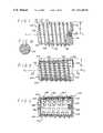
- FIG. 1is a side elevational view of a frusto-conical spinal fusion implant having a body that is frusto-conical with an external thread having a substantially uniform radius.
- FIG. 1Ais an enlarged fragmentary view along line 1 A of FIG. 1 illustrating the surface configuration of the implant of FIG. 1 .
- FIG. 3Ais an alternative embodiment of the spinal fusion implant having a frusto-conical body with an external thread radius and thread height that are not constant.
- FIG. 3is as cross sectional view along line 3 — 3 of the implant of FIG. 3A .
- FIG. 4is a side elevational view of an alternative embodiment of the spinal fusion implant having a frusto-conical body and a surface configuration comprising ratchetings for engaging bone, with wells and channels for bone ingrowth.
- FIG. 5is a cross sectional view along line 5 — 5 of the implant of FIG. 4 illustrating the channels and wells of the implant.
- FIG. 6is a cross sectional view along line 6 — 6 of the implant of FIG. 4 illustrating the channels and wells of the implant.
- FIG. 6Ais a side elevational view of an alternative embodiment of the spinal fusion implant having truncated sides forming a planar surface parallel to the longitudinal axis of the implant and ratchetings having a radius and height that are not constant.
- FIG. 6Bis a top plan view of the spinal fusion implant shown in FIG. 6A .
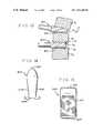
- FIG. 7is a side elevational view in partial cut-away of an alternative embodiment of the spinal fusion implant having a body that is frusto-conical and a surface configuration comprising a plurality of spaced apart posts.
- FIG. 8is a side elevational view of an alternative embodiment of the spinal fusion implant of FIG. 1 .
- FIG. 9is a side elevational view and partial cut-away of a segment of the spinal column in lordosis showing the spinal fusion implant of FIG. 8 being implanted with a driving instrument from the posterior approach to the spinal column.
- FIG. 10is a side elevational view of an alternative embodiment of the spinal fusion implant having a frusto-conical body and truncated sides.
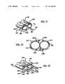
- FIG. 11is an end view along line 11 — 11 of the spinal fusion implant of FIG. 14 shown placed beside a second identical implant shown in hidden line.
- FIG. 12is a side elevational view of an alternative embodiment of the spinal fusion implant having a body with an irregular configuration.
- FIG. 13is a side elevational view of a segment of the spinal column partially in lordosis showing a first drill and a second drill used in the method of the present invention.
- FIG. 14is a side elevational view of the spinal distractor instrument of the present invention.
- FIG. 15is a top plan view of the spinal distractor instrument of FIG. 14 .
- FIG. 16is a side elevational view of a long distractor inserted into an intervertebral space.
- FIG. 17is a side elevational view of a convertible long distractor including a short distractor positioned in the intervertebral space.
- FIG. 18is a perspective view of the short distractor shown in FIG. 17 .
- FIG. 18Ais a side elevational view of the short distractor shown FIGS. 17 and 18 .
- FIG. 18Bis a side elevational view of an alternative short distractor with circumferential forward facing ratchetings.
- FIG. 18Cis a top view of the alternative short distractor of FIG. 18B .
- FIG. 18Dis a perspective view of an another alternative short distractor.
- FIG. 18Eis a top view of the alternative short distractor of FIG. 18D .
- FIG. 18Fis a side elevational view of a further alternative short distractor having knurled surfaces.
- FIG. 19is a perspective view of a spinal segment (two vertebrae and an interposed disc) with a short distractor in place, with a portion of the upper vertebrae and disc cut away to show the short distractor on one side of the spine and a long distractor about to be placed contralaterally.
- FIG. 20is a perspective view of an anterior lordotic extended outer sleeve having extended members for restoring and maintaining lordosis of the spine from the anterior aspect of the spine.
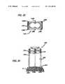
- FIG. 21is a perspective view of a dual extended outer sleeve having an extension that decreases in height in the direction of insertion.
- FIG. 22is a front elevational view of the dual extended outer sleeve shown in FIG. 21 .
- FIG. 23is a perspective view of a dual extended outer sleeve having two extensions that decrease in height in the direction insertion.
- FIG. 24is top plan view of a dual extended outer sleeve for use in installing interbody spinal implants having one or more flat sides, shown placed over two long distractors with the prongs inserted into a vertebrae.
- FIG. 25is a front elevational view of the dual extended outer sleeve shown in FIG. 24 .
- FIG. 26is a rear elevational view of the dual extended outer sleeve of FIG. 24 positioned relative a disc space to receive a drill therein.
- the first part of the Detailed Description Of The Drawingsis directed to the description of the structure of the frusto-conical implants inserted by the method of the present invention.
- the second part of the description of the drawingsis directed to the method of the present invention.
- FIG. 1a side elevational view of the spinal fusion implant for insertion with the method of the present invention generally referred to by numeral 20 is shown.
- the implant 20has a body 22 that is frusto-conical in shape such that the body 22 has a diameter (root diameter) that is generally frusto-conical.
- the body 22has an insertion end 24 and a trailing end 26 .
- the insertion end 24may include a tapered portion 25 to facilitate insertion of the spinal implant 20 .
- the body 22 of the implant 20when the implant 20 is inserted from the anterior aspect of the spine, has a maximum diameter at a point nearest to the trailing end 26 and a minimum diameter at a point nearest to the insertion end 24 .
- the implant 20has an external thread 28 having a substantially uniform radius R 1 measured from the central longitudinal axis L 1 of the implant 20 .
- the outer locus of the external thread 28(major diameter) has an overall configuration that is substantially parallel to the longitudinal axis L 1 . While the major diameter of the implant 20 is substantially uniform, the external thread 28 may be modified at the leading edge by having initially a reduced thread radius to facilitate insertion of the implant 20 and may also be modified to make the external thread 28 self-tapping.
- the external thread 28has a first thread 30 of a lesser radius than the radius R 1 of the remainder of the external thread 28 to facilitate insertion of the implant 20 .
- the second thread 32has a greater radius than the first thread 30 , but is still shorter than the radius R 1 of the remainder of the external thread 28 which is thereafter of constant radius.
- the body 22is frusto-conical substantially along the portion of the body 22 in contact with the adjacent vertebrae of the spine which allows for the creating and maintaining of the adjacent vertebrae of the spine in the appropriate angular relationship to each other in order to preserve and/or restore the normal anatomic lordosis of the spine.
- the substantially uniform radius R 1 of the external thread 28 of the implant 20allows for the engaging of the bone of the adjacent vertebrae in a position that counters the forces which tend to urge the implant 20 from between the adjacent vertebrae in the direction opposite to which the implant 20 was implanted.
- the greater thread height measured from the body 22 near the leading end 24 of the implant 20provides greater purchase into the vertebral bone and again enhances the stability of the implant 20 .
- the configuration of the external thread 28increases the surface area of the implant 20 in contact with the vertebrae to promote bone ingrowth.
- the implant 20has a recessed slot 34 at its trailing end 26 for receiving and engaging insertion instrumentation for inserting the implant 20 .
- the recessed slot 34has a threaded opening 36 for threadably attaching the implant 20 to instrumentation used for inserting the implant 20 .
- the implant 20has an outer surface 38 that is porous to present an irregular surface to the bone to promote bone ingrowth.
- the outer surface 38is also able to hold fusion promoting materials and provides for an increased surface area to engage the bone in the fusion process and to provide further stability.
- the outer surface 38 , and/or the entire implant 20may comprise any other porous material or roughened surface sufficient to hold fusion promoting substances and/or allow for bone ingrowth and/or engage the bone during the fusion process.
- the implant 20may be further coated with bioactive fusion promoting substances including, but not limited to, hydroxyapatite compounds, osteogenic proteins and bone morphogenic proteins.
- the implant 20is shown as being solid, however it is appreciated that it can be made to be substantially hollow or hollow in part.
- the implant 20for use in the lumbar spine, has an overall length in the range of approximately 24 mm to 32 mm with 26 mm being the preferred length.
- the body 22 of the implant 20has a root diameter at the insertion end 24 in the range of 8–20 mm, with 14–16 mm being the preferred root diameter at the insertion end, and a root diameter at the trailing end 26 in the range of 10–24 mm, with 16–18 mm being the preferred diameter at the trailing end 26 , when said implants are used in pairs. When used singly in the lumbar spine, the preferred diameters would be larger.
- the implant 20has a thread radius R 1 in the range of 6 mm to 12 mm, with 9–10 mm being the preferred radius R 1 .
- the implant 20has an overall length in the range of approximately 10–22 mm, with 12–14 mm being the preferred length.
- the body 22 of the implant 20has a root diameter at the insertion end 24 in the range of 8–22 mm, with 16–18 mm being the preferred root diameter at the insertion end when used singly, and 8–10 mm when used in pairs.
- the body 22 of the implant 20has a root diameter at the trailing end 26 in the range of 10–24 mm, with 18–20 mm being the preferred root diameter at the trailing end 26 when used singly, and 10–12 mm when used in pairs; a thread radius R 1 in the range of approximately 4–12 mm, with 9–10 mm being the preferred radius R 1 when inserted singularly and 5–7 mm when inserted side by side in pairs.
- the implant 120has an outer wall 144 surrounding an internal chamber 146 .
- the large and small openings 140 and 142may pass through the outer wall 144 to communicate with the internal chamber 146 .
- the internal chamber 146may be filled with bone material or any natural or artificial bone growth material or fusion promoting material such that bone growth occurs from the vertebrae through the openings 140 and 142 to the material within internal chamber 146 . While the openings 140 and 142 have been shown in the drawings as being circular, it is appreciated that the openings 140 and 142 may have any shape, size configuration or distribution, suitable for use in a spinal fusion implant without departing from the scope of the present invention.
- the implant 120has a cap 148 with a thread 150 that threadably attaches to the insertion end 124 of the spinal fusion implant 120 .
- the cap 148is removable to provide access to the internal chamber 146 , such that the internal chamber 146 can be filled and hold any natural or artificial osteoconductive, osteoinductive, osteogenic, or other fusion enhancing material.
- Some examples of such materialsare bone harvested from the patient, or bone growth inducing material such as, but not limited to, hydroxyapatite, hydroxyapatite tricalcium phosphate; or bone morphogenic protein.
- the cap 148 and/or the spinal fusion implant 120may be made of any material appropriate for human implantation including metals such as cobalt chrome, stainless steel, titanium, plastics, ceramics, composites and/or may be made of, and/or filled, and/or coated with a bone ingrowth inducing material such as, but not limited to, hydroxyapatite or hydroxyapatite tricalcium phosphate or any other osteoconductive, osteoinductive, osteogenic, or other fusion enhancing material.
- the cap 148 and the implant 120may be partially or wholly bioabsorbable.
- implant 120 ′has a body 122 ′ similar to body 122 of implant 120 and has an external thread 128 ′ having a radius R 3 measured from the central longitudinal axis L 3 of the implant 120 ′.
- the thread radius R 3is not constant throughout the length of the implant 120 ′ and the external thread 128 ′ has a thread height that is also not constant with respect to the body 122 ′ of the implant 120 ′.
- the implant 120 ′has an external thread 128 ′ with a radius R 3 that increases in size from the insertion end 124 ′ to the trailing end 126 ′ of the implant 120 ′.
- the implant 220has a frusto-conical body 222 and an outer locus that is generally frusto-conical substantially along the portion of the implant 220 that is in contact with the adjacent vertebrae of the spine.
- the implant 220has a surface configuration of forward facing ratchetings 240 suitable for engaging the bone of the adjacent vertebrae.
- Each of the plurality of ratchetings 240has a bone engaging edge 242 and ramped portion 244 .
- the ratchetings 240have a radius R 4 measured from the central longitudinal axis L 4 of the implant 220 that increases from the insertion end 224 to the trailing end 226 .
- the height of the ratchetings 240 measured from the body 222is constant throughout the length of implant 220 .
- the orientation of the ratchetings 240makes the insertion of the implant 220 easier than its removal, as the ramped portions 244 act as an inclined plane on the way in, while the bone engaging edges 242 resist motion in the opposite directions. These forward facing ratchetings 240 tend to urge the implant 220 forward until the unremoved bone of the vertebrae blocks further motion resulting in a very stable spine and implant construct.
- the bone engaging edges 242 of the ratchetings 240have a height at a highest point measured from the body 222 (root diameter) of the implant 220 in the range of 0.25–2.0 mm, with the preferred height being 0.4 mm for use in the cervical spine and 1.25 mm for use in the lumbar spine.
- the implant 220has channels 250 passing through the implant 220 and wells 260 formed in the surface of the implant 220 .
- the wells 260may or may not communicate with the channels 250 .
- the channels 250have a diameter in the range of 0.1 mm to 6 mm, with 2–3 mm being the preferred diameter.
- the wells 260have a diameter in the range of 0.1 mm to 6 mm, with 1–3 mm being the preferred diameter range. It is appreciated that although the channels 250 and wells 260 are shown having a generally rounded configuration, it is within the scope of the present invention that the channels 250 and wells 260 may have any size, shape, configuration, and distribution suitable for the intended purpose.
- FIGS. 6A and 6Ban alternative embodiment of the implant 220 is shown and generally referred to by the numeral 220 ′.
- the implant 220 ′is similar in configuration to implant 220 and has ratchetings 240 ′ having a radius R 5 measured from the longitudinal central axis L 5 that increases in size from the insertion end 224 ′ to the trailing end 226 ′.
- the ratchetings 240 ′each have a height measured from the body 222 ′ that is not constant throughout the length of the implant 220 ′.
- the ratchet radius R 5 and the ratchet heightincrease in size from the insertion end 224 ′ to the trailing end 226 ′.
- the implant 220 ′has truncated sides 270 and 272 forming two planar surfaces which are diametrically opposite and are parallel to the longitudinal axis L 4 .
- two implants 220 ′may be placed side by side with one of the sides 270 or 272 of each implant touching, such that the area of contact with the bone of the adjacent vertebrae and the ratchetings 240 ′ is maximized.
- the implant 220 ′may have one truncated side.
- FIG. 7a side elevational view in partial cut-away of an alternative embodiment of the implant of the present invention is shown and generally referred to by the numeral 420 .
- the implant 420has a body 422 that is frusto-conical in shape substantially along the portion of the implant 420 that is in contact with the adjacent vertebrae of the spine and has an insertion end 424 and a trailing end 426 .
- the implant 420has an outer surface 438 that is capable of receiving and holding bone, or other materials capable of participating in the fusion process and/or capable of promoting bone ingrowth.
- the surface 438comprises a plurality of posts 440 that are spaced apart to provide a plurality of interstices 442 which are partial wells with incomplete walls capable of holding and retaining milled bone material or any artificial bone ingrowth promoting material.
- the implant 420may be prepared for implantation by grouting or otherwise coating the surface 438 with the appropriate fusion promoting substances.
- FIG. 8a side elevational view of an alternative embodiment of the spinal fusion implant of the present invention generally referred to by numeral 520 is shown.
- the implant 520has a body 522 having a root diameter that is frusto-conical in the reverse direction as that of implant 20 shown in FIG. 1 , in order to preserve and/or restore lordosis in a segment of spinal column when inserted from the posterior aspect of the spine.
- the body 522has an insertion end 524 and a trailing end 526 .
- the body 522 of the implant 520has a minimum diameter at a point nearest to the trailing end 526 and a maximum diameter at a point nearest to the insertion end 524 .
- the insertion end 524may have an anterior nose cone portion 530 presenting a tapered end to facilitate insertion.
- the implant 520has an external thread 528 having a substantially uniform radius R 6 measured from the central longitudinal axis L 6 of the implant 520 , such that the external diameter of the external thread 528 (major diameter) has an overall configuration that is substantially parallel to the longitudinal axis L 6 . It is appreciated that the thread 528 can have a major diameter that varies with respect to the longitudinal axis L 6 , such that the major diameter may increase from the insertion end 524 to the trailing end 526 or the reverse.
- the external thread 528has a thread height measured from the body 522 that increases from the insertion end 524 to the trailing end 526 .
- a segment of the spinal column Sis shown with the vertebrae V 1 and V 2 in lordosis and an implant 520 shown being inserted from the posterior aspect of the spinal column S with an instrument driver D.
- the implant 520is inserted with the larger diameter insertion end 524 first in order to in initially distract apart the vertebrae V 1 and V 2 which then angle toward each other posteriorly as the implant 520 is fully inserted. It is appreciated that the insertion of implant 520 does not require the adjacent vertebrae V 1 and V 2 to be placed in lordosis prior to insertion, as the full insertion of the implant 520 itself is capable of creating the desired lordotic angular relationship of the two vertebrae V 1 and V 2 .
- the implant 520for use in said lumbar spine, has an overall length in the range of approximately 24 mm to 30 mm, with 26 mm being the preferred length.
- the body 522 of the implant 520has a root diameter at the insertion end 524 in the range of 12–22 mm, with 16 mm being the preferred root diameter at the insertion end, and a root diameter at the trailing end 526 in the range of 10–20 mm, with 14 mm being the preferred diameter at the trailing end 526 .
- the imp 520has a thread radius R 6 in the range of 6 mm to 12 mm, with 8 mm being the preferred radius R 6 .
- FIG. 10an alternative embodiment of the spinal fusion implant of the present invention generally referred to by the numeral 620 and a partial fragmentary view of a second identical implant, generally referred to by the numeral 621 are shown.
- the implant 620has a body 622 that is partially frusto-conical in shape similar to body 22 of implant 20 shown in FIG. 1 , and has an insertion end 624 and a trailing end 626 .
- the body 622 of the implant 620has truncated sides 670 and 672 forming planar surfaces that are parallel to the longitudinal axis L 7 .
- two implants 620 and 621may be placed side by side, with one of the sides 670 or 672 of each implant with little space between them, such that the area of contact with the bone of the adjacent vertebrae is maximized.
- the body 622may also be cylindrical in shape and have truncated sides 670 and 672 .
- the implant 620has an external thread 628 having a radius R 6 measured from the central longitudinal axis L 7 that may be constant, such that the major diameter or outer locus of the external thread 628 has an overall configuration that is substantially cylindrical. It is appreciated that the external thread 628 may have a thread radius R 7 that is variable with respect to the longitudinal axis L 7 such that the major diameter or outer locus of the external thread 628 has an overall configuration that is substantially frusto-conical.
- FIG. 11an end view of the implant 620 placed beside implant 621 is shown.
- the implant 620has a thread radius that is substantially constant and has a thread height measured from the body 622 that is greater at the sides 670 and 672 .
- two implants 620 and 621can be placed beside each other with the external thread 628 of each implant interdigitated allowing for closer adjacent placement of the two implants as a result of the substantial overlap of the external thread 628 at the side 670 or 672 of the implants.
- an alternative embodiment of the implant of the present inventionis shown and generally referred to by the numeral 700 .
- the implant 700is similar in configuration to implant 20 shown in FIG. 1 , except that the body 722 has an irregular configuration.
- the configuration of the body 722has a root diameter D which is variable in size throughout the length of the implant 700 and, as shown in this embodiment, comprises larger diameter portions 750 and smaller diameter portions 752 . It is appreciated that each of the large diameter portions 750 may be of the same or different diameter and each of the smaller diameter portions 752 may be of the same or different diameter.
- the outer surface of the body 722 of implant 720may be filled with fusion promoting substances such that the smaller diameter portions 752 may hold such fusion promoting substances. If so filled, the composite of the implant 700 and the fusion promoting material could still produce an even external surface of the body 722 if so desired.
- the diseased disc between two vertebraeis at least partially removed from the anterior aspect of the spine.
- the two vertebrae adjacent the diseased discare then optimally distracted and placed in the desired amount of lordosis by any of a number of well known means including, but not limited to, those means that distract the vertebral bodies by engaging screws placed into the anterior aspect of the vertebral bodies, and disc space distractors that are placed from the anterior aspect of the spine into the disc space and are then used to urge the vertebral endplates away from each other and into lordosis.
- a frusto-conical spaceis created from anterior to posterior between the adjacent vertebrae.
- the frusto-conical space that is createdis greater in diameter than the disc space height, such that some bone is removed from each of the adjacent vertebrae.
- the created spaceis generally frusto-conical in shape, being greatest in diameter anteriorly and tapering to a lesser diameter posteriorly.
- the spineis of sufficient width, it may be possible to prepare two such frusto-conical spaces side-by-side at the same disc level, allowing for the use of two implants instead of one. In either event, once the frusto-conical space is prepared and all debris removed, the implant is then inserted into the prepared space across the disc space, penetrating into each of the adjacent vertebrae, from anterior to posterior.
- the diseased discis first removed by conventional discectomy.
- the depth of the disc spaceis then determined by direct measurement.
- An interspace distractorsuch as that described by Michelson in U.S. Pat. No. 6,080,155, incorporated herein by reference, is then inserted into the disc space.
- a series of such distractorsare available and are sequentially inserted until the optimal amount of distraction across the disc space is achieved.
- the interspace distractors utilized for this purposeare wedged so as to induce physiological lordosis.
- a disc penetrating portion 1002 of a long distractor 1000is inserted under direct vision into the intervertebral (or disc) space and disc D'between the vertebral bodies V'.
- the penetrating portion 1002is essentially cylindrical with a bullet-shaped front end 1004 and a shoulder portion 1006 where the penetrating portion 1002 extends from barrel 1008 .
- the penetrating portion 1002urges the vertebral bodies apart, facilitating the introduction of the instruments.
- Long distractors with sequentially increasing diameter penetrating portions 1002are then introduced. As the optimal diameter of penetrating portion 1002 is achieved, the vertebrae V' to either side are forced into full congruence and thus become parallel, not only to the penetrating portion 1002 , but to each other.
- a convertible long distractor 1010is used on the first side of the spine.
- the convertible long distractor 1010has a barrel portion 1012 separable from a short distractor 1014 . While the initial distraction may be performed with a solid long distractor, as the optimal distraction is approached the appropriate convertible long distractor is utilized.
- the barrel portion 1012includes a rectangular projection (or male mating member) 1016 at one end, and the short distractor 1014 has an increased diameter head 1018 , a female rectangular slot 1020 and an internal threaded opening 1022 .
- the short distractor 1014is removably attached to the barrel portion 1012 via the mating of female rectangular slot 1020 and the male mating member 1016 .
- the mating of the female rectangular slot 1020 and the male mating member 1016is held together by threading a threaded working end screw 1024 of an interior shaft 1026 extending through the barrel portion 1012 into the female rectangular slot 1020 .
- the threaded working end screw 1024corresponds to the internal threaded opening 1022 .
- a knob 1028serves to drive a crown 1030 connected to the interior shaft 1026 .
- the knob 1028has a open socket 1032 for fitting around the crown 1030 , and engages a reduced diameter hexagonal portion 1034 of the crown 1030 to rotate the interior shaft 1026 and the threaded working end screw 1024 .
- a detent ball 1036 on the inside of the open socket 1032engages a detent 1037 in the crown 1030 to hold the knob 1028 and the crown 1030 together.
- the short distractor 1014 shown thereinare designed to provide for high stability when temporarily situated so as to resist inadvertent migration while the surgeon is working on the second side.
- the embodiment of the short distractor 1014 shown in FIGS. 17 , 18 , and 18 Ahas a pair of sharp pegs (or prongs) 1038 , to embed into the opposing vertebral bodies and forward facing ratchetings 1039 , that further resist backward movement.
- FIGS. 17 , 18 , and 18 A- 18 Fthe short distractor 1014 shown therein are designed to provide for high stability when temporarily situated so as to resist inadvertent migration while the surgeon is working on the second side.
- the embodiment of the short distractor 1014 shown in FIGS. 17 , 18 , and 18 Ahas a pair of sharp pegs (or prongs) 1038 , to embed into the opposing vertebral bodies and forward facing ratchetings 1039 , that further resist backward movement.
- FIGS. 18B and 18Care side and top views of an alternative embodiment of the a short distractor 1014 such that the distractor portion to be interposed between the vertebrae is essentially cylindrical, but with circumferential forward facing ratchetings 1039 .
- FIGS. 18D and 18Eanother alternative embodiment of the short distractor 1014 is shown having a more rectangularized design, with forward facing ratchetings, without the sharp prongs 1038 of FIGS. 17 , 18 , and 18 A.
- FIG. 18Fis a side view of a further alternative embodiment of the short distractor 1014 shown with knurling, to increase the interference with the bone surface so as to add stability to the unit and to resist dislodgment.
- both the long and short distractorscan have a variety of configurations consistent with their purpose, and that surface irregularities as well as the shape of the ends themselves, with or without prongs 1038 , may be utilized to make the short distractor 1014 more resistant to migration.
- the convertible distractor 1010is dissociated, leaving the short distractor 1014 in place.
- the surgeonthen moves to the other side of the spine at the same disc level, and retracts the dural sac and nerve root medially, exposing the disc on that side.
- Long distractors 1000are then sequentially inserted into the disc space until the diameter of the distractor on the second side is at least as big as that on the first side.
- outer sleeveis then fitted over the barrel portion of the interspace distractor barrel 1008 of long distractor 1000 or barrel 1012 of convertible distractor 1010 and firmly seated in engagement with the spine.
- the outer sleevemay itself have extended portions capable of either maintaining or of obtaining and maintaining distraction.
- the outer sleevemay also have vertebrae engaging prongs to further stabilize the outer sleeve to the spine and to more rigidly control motion at the adjacent vertebrae. As discussed below and described in U.S. Pat. No.
- the anterior extended outer sleeve 1040for use from the anterior approach of the spine is shown.
- the anterior extended outer sleeve 1040comprises a hollow tubular member 1042 having a distal end 1044 which has been extended such that a pair of extended portions 1046 and 1048 which are essentially a continuation of the tubular member 1042 and are opposed 180 degrees from each other.
- the extended portions 1046 and 1048are configured to restore and maintain lordosis of the spine from the anterior approach.
- the extended portions 1046 and 1048each have a height that is greater at a point proximate to the distal end 1044 of the tubular member 1042 that decreases in the direction away from the tubular member 1042 .
- the extended portions 1046 and 1048are tapered at their leading edges 1050 and 1052 , respectively, to facilitate insertion into the disc space.
- anterior extended outer sleeve 1040 for use anteriorlyis shown in the singular form and in use in the lumbar spine, it is understood that it may take a double barrelled form and in either form, be used throughout the spine.
- a dual extended outer sleeveis shown and generally referred to by the numeral 1060 .
- the dual extended outer sleeve 1060comprises two hollow tubular members 1062 and 1064 .
- the two hollow tubular members 1062 and 1064have a distal end 1066 which has been extended to form an extended portion 1068 which is essentially a continuation of the hollow tubular members 1062 and 1064 joined together.
- the extended portion 1068is similar in shape and function to the extended portions 1046 and 1048 described above in reference to FIG. 20 .
- the extended portion 1068has a height that is greater at a point proximate the distal end 1066 and decreases in the direction away from the hollow members 1062 and 1064 , in order to maintain the normal curvature of the spine by correcting the angular relationships of the vertebrae V'.
- the extended portion 1068is tapered at its leading edge 1070 to facilitate insertion of the extended portion 1068 into the disc space between two adjacent vertebrae V'.
- Located at the distal end of the tubular members 1062 and 1064are sharpened teeth 1072 for engaging the vertebrae V'.
- the tubular members 1062 and 1064may be bridged in part or wholly throughout their length, but are typically fixed by a foot plate 1074 .
- the foot plate 1074has an oval configuration that contours and hugs the vertebrae V' and has a plurality of prongs 1076 A- 1076 D extending from the foot plate 1074 is shown.
- the prongs 1076 A- 1076 Dare sufficiently long to engage the bone of adjacent vertebrae V', but limited in length so as not to over penetrate beyond the vertebrae once inserted.
- FIG. 23another dual extended outer sleeve 1080 having two hollow tubular members 1082 and 1084 is shown.
- the dual extended outer sleeve 1080is similar to the dual extended outer sleeve 1060 , except that it has additional extended portions 1086 , 1087 and 1088 which have a height that is greater near the distal end 1090 of the hollow tubular members 1082 and 1084 and decreases in the direction away from the hollow tubular members 1082 and 1084 .
- the extended portions 1086 , 1087 and 1088are similar in shape and function to the extended portions 1046 and 1048 described above in reference to FIG. 20 .
- a foot plate 1092is also provided. As the foot plate 1092 is rectangular and larger than foot plate 1074 , prongs 1094 E and 1094 F, in addition to prongs 1094 - 1094 D, may be added.
- FIG. 13a segment of the spinal column S is shown with vertebrae V 1 and V 2 shown in lordosis adjacent to disc space D 1 and vertebrae V 2 and V 3 shown not in lordosis, but relatively parallel to each other adjacent disc space D 2 .
- a first drill 810 making an opening 812 across the disc space D 1 , and into adjacent vertebrae V 1 and V 2 , and a second drill 820 making an opening 822 across the disc space D 2 and into adjacent vertebrae V 2 and V 3are shown in FIG. 13 .
- the interbody spinal fusion implantitself is threaded and frusto-conical in shape and therefore, the remaining portion of the procedure will be described in regard to that particular embodiment of the present invention, by way of example.
- the spineWith the disc space fully distracted and in anatomical lordosis and with the outer sleeve firmly engaged to the spine, it is then desirable to prepare the spine for receipt of the interbody fusion implant. It is preferable to prepare a space across the disc space and penetrating into the adjacent vertebrae which space corresponds roughly to the root dimensions of the implant to be implanted.
- a stopped-out bone cutting instrumentis inserted through the outer sleeve, the shape of the cutting portion of the first drill 810 generally corresponding to the frusto-conical shape of the root diameter of the implant being inserted.
- This instrumentmay take the form of a frusto-conical drill or a mill and may be used to cut the bone by rotation, said rotation being achieved either through a manual handle or with power. Having prepared the space, the surgeon has two options. One is to remove the outer sleeve and then, because the implant is itself frusto-conical, screw the implant in using an implant driver capable of locking to the implant. The other is to leave the outer sleeve in place during the insertion of the implant.
- the insertion of the implant itselfcauses a reproduction of the previous distraction which is easily achieved as the implant itself is frusto-conical in shape and the space created by the removal of the bone to either side of the disc space essentially corresponds to the root diameter of the implant such that as the implant is inserted, the threads are embedded into the vertebrae adjacent the disc space.
- the procedureis performed in the same manner except that either a double-barreled outer sleeve may be used or the previously described procedure essentially performed twice at the same disc level, such that a pair of implants may be inserted side-by-side.
- the bone removing portion of the drilling meansneeds to generally correspond to the root diameter of the implant while the inside diameter of the outer sleeve needs to be great enough to allow the passage of the major diameter of the implant. It is desirable to stabilize the bone removal instrument and to assure that it removes equal portions of bone from each of the adjacent vertebrae.
- Thismay be achieved by a reduction sleeve which fits between the bone removal means and the inner wall of the outer sleeve and which essentially corresponds to the difference between the minor and major diameters of the implant, or some portion of the drill shaft proximal to the cutting end may have a diameter which corresponds to the major diameter of the implant even while the distal bone removing portion corresponds to the root diameter of the implant. In either way, the bone removal instrument is both stabilized and centered within the outer sleeve.
- the approach to the lumbar spinemay either be retroperitoneal, or transperitoneal.
- the proceduremay be performed under direct vision, or laproscopically with the use of an endoscope.
- the implantsmay be inserted using either a single-barreled or double-barreled outer sleeve as described above, and by the methods previously described U.S. Pat. No. 6,080,155 from which the present methods differ only in the shape of the drill end or bone milling device which is essentially conical.
- the methodscan be utilized for the insertion of non-threaded implants (such as implants 222') in which case the implants are linearly advanced rather than threaded in.
- the implantsthemselves may have truncations on the sides to form a planar surface parallel to the longitudinal axis of the implant, such that it is possible to fit two such implants more closely together by narrowing the width of each while preserving their height.
- a tapmay be used after the drilling step and prior to the insertion of the implants.
- a dual outer sleeve 1100 having a pair of overlapping, hollow cylindrical tubes 1102 and 1104can be utilized as shown in FIGS. 24-26 .
- the cylindrical tubes 1102 and 1104are identical in size and each has an internal diameter slightly larger than the outer diameter of the spinal fusion implant to be inserted therethrough.
- the cylindrical tubes 1102 and 1104are in communication with each other along their length and are displaced from each other ideally a distance that is slightly greater than the sum of the diameters of two spinal fusion implants 220 ' placed side-by-side with the flat sides 270 of each of the spinal fusion implants touching.
- the cylindrical tubes 1102 and 1104are joined longitudinally such that they are partially overlapping.
- the cylindrical tubes 1102 and 1104are mounted on a foot plate 1106 similar to the foot plate 1092 shown in FIG. 23 .
- the dual outer sleeve 1100is introduced over two long distractors 1110 and 1112 placed side-by-side and protruding anteriorly from the vertebrae V'.
- the long distractors 1110 and 1112are similar to the long distractor 1000 described above except that they have a flat side 1114 and 1116 respectively.
- the foot plate 1106is contoured so as to approximate the external curvature of the vertebrae V'anteriorly.
- the sharp prongs 1108 A- 1108 Fare sufficiently long to permit fixation of the foot plate 1106 , but are limited in length so as to not penetrate the vertebrae V' too far posteriorly and number from 2 to 10, but preferably 6.
- the dual outer sleevehas been described above for inserting two implants each having at least one flat side, and may have extended portions for insertion into the disc space which are capable of producing distraction as well as lordosis as previously described with such extensions extending in line with the lateral walls of the cylindrical tubes.
- one of the long distractors 1110 and 1112is removed and the surgeon may drill the disc space D' between the vertebrae V' utilizing drill 1120 using each of the hollow cylindrical tubes 1102 and 1104 to guide the drill 1120 in order to create overlapping holes in which the spinal fusion implants 220 ' may be inserted. Further, the removal of disc and bone may be accomplished by the use of a burr, or a chisel of appropriate shape for that purpose and with or without the use of a drill.
- an implant driver instrumentis used to insert the spinal fusion implants 220 ' preferably by linear advancement. The implant driver instrument may be used to either insert or to remove the spinal fusion implants 220 '.
- the use of at least partially frusto-conical interbody spinal fusion implantsallows for the creation of lordosis by the implant itself where none is present to begin with as with the angular relationship of V 2 and V 3 shown in FIG. 13 .
- the disc space D 2which in the preferred circumstance would be fully distracted but need not be, but lacking lordosis, could have a bore drilled across that space such that equal arcs of bone A 1 and A 2 are removed from each of the adjacent vertebrae V 2 and V 3 using a drill 820 or bone milling device capable of producing a cylindrical bore. Where one such boring is performed, it would generally be in the center line and directed from anterior to posterior.
- the use of the substantially cylindrical bone drill 820provides for the removal of a generally uniform thickness of bone from each of the adjacent vertebrae from anterior to posterior.
- spinal distractor 900is shown which is used for distracting the adjacent vertebrae in lordosis prior to the bone removal step.
- the spinal distractor 900has a tapered insertion end 902 to facilitate insertion, an instrument engaging end 904 , and top and bottom surfaces 906 and 908 .
- the top and bottom surfaces 906 and 908are in a angular relationship to each other and are furthest apart at a point near the insertion end 902 to produce the desired lordosis when inserted in the disc space between two adjacent vertebrae.
- the top and bottom surfaces 906 and 908have surface roughenings 910 for engaging the bone of the adjacent vertebrae and stabilizing the spinal distractor 900 when inserted.
Landscapes
- Health & Medical Sciences (AREA)
- Engineering & Computer Science (AREA)
- Biomedical Technology (AREA)
- Orthopedic Medicine & Surgery (AREA)
- Life Sciences & Earth Sciences (AREA)
- Animal Behavior & Ethology (AREA)
- Veterinary Medicine (AREA)
- Public Health (AREA)
- Transplantation (AREA)
- General Health & Medical Sciences (AREA)
- Oral & Maxillofacial Surgery (AREA)
- Heart & Thoracic Surgery (AREA)
- Vascular Medicine (AREA)
- Cardiology (AREA)
- Neurology (AREA)
- Surgery (AREA)
- Physical Education & Sports Medicine (AREA)
- Dentistry (AREA)
- Nuclear Medicine, Radiotherapy & Molecular Imaging (AREA)
- Medical Informatics (AREA)
- Molecular Biology (AREA)
- Prostheses (AREA)
Abstract
Description
- 1. Because the spinal fusion implants of the present invention are at least partially frusto-conical in shape, those that taper from the leading edge to the trailing edge they are easy to introduce and easy to fully insert into the spinal segment to be fused. In the preferred embodiment, where the leading edge of the implant is larger than the trailing edge, the implant utilizes a tapered forward portion and an increasing thread height relative to the body from the leading edge to the trailing edge to facilitate insertion.
- 2. The shape of the implants of the present invention is consistent with the shape of the disc, which the implants at least in part replace, wherein the front of the disc is normally taller than the back of the disc, which allows for normal lordosis. The implants of the present invention are similarly taller anteriorly than they are posteriorly.
- 3. The spinal fusion implants of the present invention allow for a minimal and uniform removal of bone from the vertebrae adjacent the disc space while still providing for an interbody fusion in lordosis when properly inserted.
- 4. The spinal fusion implants of the present invention conform to a geometric shape, which shape is readily producible at the site of fusion, to receive said spinal fusion implants.
Claims (21)
Priority Applications (1)
| Application Number | Priority Date | Filing Date | Title |
|---|---|---|---|
| US09/412,082US7291149B1 (en) | 1995-06-07 | 1999-10-04 | Method for inserting interbody spinal fusion implants |
Applications Claiming Priority (2)
| Application Number | Priority Date | Filing Date | Title |
|---|---|---|---|
| US08/480,904US6210412B1 (en) | 1988-06-13 | 1995-06-07 | Method for inserting frusto-conical interbody spinal fusion implants |
| US09/412,082US7291149B1 (en) | 1995-06-07 | 1999-10-04 | Method for inserting interbody spinal fusion implants |
Related Parent Applications (1)
| Application Number | Title | Priority Date | Filing Date |
|---|---|---|---|
| US08/480,904ContinuationUS6210412B1 (en) | 1988-06-13 | 1995-06-07 | Method for inserting frusto-conical interbody spinal fusion implants |
Publications (1)
| Publication Number | Publication Date |
|---|---|
| US7291149B1true US7291149B1 (en) | 2007-11-06 |
Family
ID=38653365
Family Applications (1)
| Application Number | Title | Priority Date | Filing Date |
|---|---|---|---|
| US09/412,082Expired - Fee RelatedUS7291149B1 (en) | 1995-06-07 | 1999-10-04 | Method for inserting interbody spinal fusion implants |
Country Status (1)
| Country | Link |
|---|---|
| US (1) | US7291149B1 (en) |
Cited By (59)
| Publication number | Priority date | Publication date | Assignee | Title |
|---|---|---|---|---|
| US20070055374A1 (en)* | 2004-02-13 | 2007-03-08 | Copf, Franz, Jr. | Intervertebral implant and surgical method for spondylodesis of a lumbar vertebral column |
| USD603502S1 (en)* | 2007-12-03 | 2009-11-03 | Orthopedic Development Corporation | Surgical impactor |
| US20100161061A1 (en)* | 2008-12-18 | 2010-06-24 | Jessee Hunt | Truss implant |
| US7824431B2 (en) | 2006-12-29 | 2010-11-02 | Providence Medical Technology, Inc. | Cervical distraction method |
| WO2012009162A1 (en)* | 2010-07-12 | 2012-01-19 | Depuy Spine, Inc. | Pedicular facet fusion screw with plate |
| US8197513B2 (en) | 2007-04-13 | 2012-06-12 | Depuy Spine, Inc. | Facet fixation and fusion wedge and method of use |
| US8267966B2 (en) | 2008-06-06 | 2012-09-18 | Providence Medical Technology, Inc. | Facet joint implants and delivery tools |
| USRE43714E1 (en) | 1999-12-15 | 2012-10-02 | Zimmer Orthobiologics, Inc. | Preparation for repairing cartilage defects or cartilage/bone defects in human or animal joints |
| US8313528B1 (en) | 2008-03-27 | 2012-11-20 | Spinelogik, Inc. | Intervertebral fusion device and method of use |
| US8333804B1 (en) | 2008-03-27 | 2012-12-18 | Spinelogik, Inc. | Intervertebral fusion device and method of use |
| US8361152B2 (en) | 2008-06-06 | 2013-01-29 | Providence Medical Technology, Inc. | Facet joint implants and delivery tools |
| US8512347B2 (en) | 2008-06-06 | 2013-08-20 | Providence Medical Technology, Inc. | Cervical distraction/implant delivery device |
| US8753406B2 (en) | 2010-08-31 | 2014-06-17 | Zimmer Inc. | Osteochondral graft delivery device and uses thereof |
| US20140277502A1 (en)* | 2013-03-15 | 2014-09-18 | NuTech Spine, Inc. | Anterior Lumbar Fusion Method and Device |
| US8894685B2 (en) | 2007-04-13 | 2014-11-25 | DePuy Synthes Products, LLC | Facet fixation and fusion screw and washer assembly and method of use |
| US9005288B2 (en) | 2008-01-09 | 2015-04-14 | Providence Medical Techonlogy, Inc. | Methods and apparatus for accessing and treating the facet joint |
| USD732667S1 (en) | 2012-10-23 | 2015-06-23 | Providence Medical Technology, Inc. | Cage spinal implant |
| USD745156S1 (en) | 2012-10-23 | 2015-12-08 | Providence Medical Technology, Inc. | Spinal implant |
| US20160000554A1 (en)* | 2013-03-06 | 2016-01-07 | University Of Pittsburgh - Of The Commonwealth System Of Higher Education | Apparatus and method for regeneration of ligaments and tendons |
| US9271845B2 (en) | 2012-09-25 | 2016-03-01 | 4Web | Programmable implants and methods of using programmable implants to repair bone structures |
| US9333086B2 (en) | 2008-06-06 | 2016-05-10 | Providence Medical Technology, Inc. | Spinal facet cage implant |
| US9381049B2 (en) | 2008-06-06 | 2016-07-05 | Providence Medical Technology, Inc. | Composite spinal facet implant with textured surfaces |
| US9427324B1 (en) | 2010-02-22 | 2016-08-30 | Spinelogik, Inc. | Intervertebral fusion device and method of use |
| US9451986B2 (en)* | 2013-01-24 | 2016-09-27 | Michael R. Stoffman | Percutaneous sacroiliac joint implant and method for surgically inserting and securing the implant into the sacroiliac joint |
| US9636226B2 (en) | 2013-03-15 | 2017-05-02 | 4Web, Inc. | Traumatic bone fracture repair systems and methods |
| US9730802B1 (en) | 2014-01-14 | 2017-08-15 | Nuvasive, Inc. | Spinal fusion implant and related methods |
| EP3213704A1 (en) | 2016-02-26 | 2017-09-06 | LDR Medical | System of spinal arthodesis implants |
| US9867714B1 (en) | 2011-09-23 | 2018-01-16 | Samy Abdou | Spinal fixation devices and methods of use |
| US10045768B2 (en) | 2014-07-06 | 2018-08-14 | Javier Garcia-Bengochea | Methods and devices for surgical access |
| US10111757B2 (en) | 2012-10-22 | 2018-10-30 | Cogent Spine, LLC | Devices and methods for spinal stabilization and instrumentation |
| US10201375B2 (en) | 2014-05-28 | 2019-02-12 | Providence Medical Technology, Inc. | Lateral mass fixation system |
| USD841165S1 (en) | 2015-10-13 | 2019-02-19 | Providence Medical Technology, Inc. | Cervical cage |
| US10543107B2 (en) | 2009-12-07 | 2020-01-28 | Samy Abdou | Devices and methods for minimally invasive spinal stabilization and instrumentation |
| US10548740B1 (en) | 2016-10-25 | 2020-02-04 | Samy Abdou | Devices and methods for vertebral bone realignment |
| US10682243B2 (en) | 2015-10-13 | 2020-06-16 | Providence Medical Technology, Inc. | Spinal joint implant delivery device and system |
| USD887552S1 (en) | 2016-07-01 | 2020-06-16 | Providence Medical Technology, Inc. | Cervical cage |
| US10687830B2 (en) | 2015-07-06 | 2020-06-23 | Javier Garcia-Bengochea | Methods and devices for surgical access |
| US10695105B2 (en) | 2012-08-28 | 2020-06-30 | Samy Abdou | Spinal fixation devices and methods of use |
| US10857003B1 (en) | 2015-10-14 | 2020-12-08 | Samy Abdou | Devices and methods for vertebral stabilization |
| US10918498B2 (en) | 2004-11-24 | 2021-02-16 | Samy Abdou | Devices and methods for inter-vertebral orthopedic device placement |
| USD911525S1 (en) | 2019-06-21 | 2021-02-23 | Providence Medical Technology, Inc. | Spinal cage |
| US10973648B1 (en) | 2016-10-25 | 2021-04-13 | Samy Abdou | Devices and methods for vertebral bone realignment |
| US11006982B2 (en) | 2012-02-22 | 2021-05-18 | Samy Abdou | Spinous process fixation devices and methods of use |
| US11065039B2 (en) | 2016-06-28 | 2021-07-20 | Providence Medical Technology, Inc. | Spinal implant and methods of using the same |
| USD933230S1 (en) | 2019-04-15 | 2021-10-12 | Providence Medical Technology, Inc. | Cervical cage |
| US11179248B2 (en) | 2018-10-02 | 2021-11-23 | Samy Abdou | Devices and methods for spinal implantation |
| US11224521B2 (en) | 2008-06-06 | 2022-01-18 | Providence Medical Technology, Inc. | Cervical distraction/implant delivery device |
| USD945621S1 (en) | 2020-02-27 | 2022-03-08 | Providence Medical Technology, Inc. | Spinal cage |
| US11272964B2 (en) | 2008-06-06 | 2022-03-15 | Providence Medical Technology, Inc. | Vertebral joint implants and delivery tools |
| US20220183713A1 (en)* | 2019-03-26 | 2022-06-16 | Covidien Lp | Ultrasonic and multi-energy surgical instruments, systems, and methods for sealing, cutting, and/or sensing tissue |
| US11648128B2 (en) | 2018-01-04 | 2023-05-16 | Providence Medical Technology, Inc. | Facet screw and delivery device |
| US11871968B2 (en) | 2017-05-19 | 2024-01-16 | Providence Medical Technology, Inc. | Spinal fixation access and delivery system |
| US12004781B2 (en) | 2014-05-27 | 2024-06-11 | Providence Medical Technology, Inc. | Lateral mass fixation implant |
| US12102535B2 (en) | 2019-11-15 | 2024-10-01 | 4Web, Llc | Piezoelectric coated implants and methods of using piezoelectric coated implants to repair bone structures |
| US12115071B2 (en) | 2012-09-25 | 2024-10-15 | 4Web, Llc | Programmable intramedullary implants and methods of using programmable intramedullary implants to repair bone structures |
| US12144513B2 (en) | 2018-09-21 | 2024-11-19 | Providence Medical Technology, Inc. | Vertebral joint access and decortication devices and methods of using |
| US12201531B2 (en) | 2020-07-08 | 2025-01-21 | 4Web, Llc | Implants having bone growth promoting agents contained within biodegradable materials |
| US12279964B2 (en) | 2008-12-18 | 2025-04-22 | 4Web, Llc | Implants having bone growth promoting agents and methods of using such implants to repair bone structures |
| USD1098431S1 (en) | 2023-02-27 | 2025-10-14 | Providence Medical Technology, Inc. | Spinal cage |
Citations (253)
| Publication number | Priority date | Publication date | Assignee | Title |
|---|---|---|---|---|
| US350420A (en) | 1886-10-05 | Staple-driving implement | ||
| US1137585A (en) | 1915-02-05 | 1915-04-27 | Thornton Craig Jr | Dental appliance. |
| US2065659A (en) | 1934-08-04 | 1936-12-29 | Arthur V Cullen | Fastening method and means |
| US2181746A (en) | 1939-02-04 | 1939-11-28 | John R Siebrandt | Combination bone clamp and adjustable drill guide |
| US2243718A (en) | 1938-11-05 | 1941-05-27 | Moreira Francisco Elias Godoy | Surgical drill |
| US2372622A (en) | 1943-01-28 | 1945-03-27 | Courtaulds Ltd | Manufacture and production of artificial threads, filaments, and the like |
| US2514665A (en) | 1949-01-11 | 1950-07-11 | Myller Ernest | Medical instrument |
| US2537070A (en) | 1948-12-27 | 1951-01-09 | Puy Mfg Company Inc De | Surgical appliance and method for fixation of bone fragments |
| US2543780A (en) | 1946-12-09 | 1951-03-06 | Herbert E Hipps | Bone graft apparatus |
| US2677369A (en) | 1952-03-26 | 1954-05-04 | Fred L Knowles | Apparatus for treatment of the spinal column |
| US2774350A (en) | 1952-09-08 | 1956-12-18 | Jr Carl S Cleveland | Spinal clamp or splint |
| US2789558A (en) | 1953-09-17 | 1957-04-23 | Leslie V Rush | Medullary in driver and extractor |
| US2832343A (en) | 1955-04-12 | 1958-04-29 | Mose Clara Emilie Marie | Dilators |
| US2842131A (en) | 1957-05-27 | 1958-07-08 | George W Smith | Automatic drill |
| US2878809A (en) | 1958-01-23 | 1959-03-24 | Richards Mfg Company | Surgical drill attachment |
| US3128768A (en) | 1961-11-24 | 1964-04-14 | Rosemount Eng Co Ltd | Surgical drill |
| US3298372A (en) | 1963-12-17 | 1967-01-17 | Feinberg Maurice | Surgical hydrocephalus shunt sleeve for placement in a vertebra |
| DE1961531U (en) | 1962-06-04 | 1967-06-08 | Auxiliaire De Gestion Charbonn | FURNACE FOR THERMAL TREATMENT OF FUEL BRIQUETTES OR CLASSIFIED COAL. |
| US3426364A (en) | 1966-08-25 | 1969-02-11 | Colorado State Univ Research F | Prosthetic appliance for replacing one or more natural vertebrae |
| US3486505A (en) | 1967-05-22 | 1969-12-30 | Gordon M Morrison | Orthopedic surgical instrument |
| US3604487A (en) | 1969-03-10 | 1971-09-14 | Richard S Gilbert | Orthopedic screw driving means |
| US3605123A (en) | 1969-04-29 | 1971-09-20 | Melpar Inc | Bone implant |
| US3618611A (en) | 1969-03-05 | 1971-11-09 | Julius C Urban | Vacuum rotary dissector |
| US3709219A (en) | 1970-11-27 | 1973-01-09 | W Halloran | Bone compression device |
| US3719186A (en) | 1971-04-22 | 1973-03-06 | Univ Alabama In Birmingham | Surgical instrument for placement of bone pins and holes therefor |
| US3720959A (en) | 1970-08-26 | 1973-03-20 | G Hahn | Mandibular prosthetic apparatus |
| US3750652A (en) | 1971-03-05 | 1973-08-07 | J Sherwin | Knee retractor |
| US3848601A (en) | 1972-06-14 | 1974-11-19 | G Ma | Method for interbody fusion of the spine |
| US3855638A (en) | 1970-06-04 | 1974-12-24 | Ontario Research Foundation | Surgical prosthetic device with porous metal coating |
| US3867950A (en) | 1971-06-18 | 1975-02-25 | Univ Johns Hopkins | Fixed rate rechargeable cardiac pacemaker |
| US3867728A (en) | 1971-12-30 | 1975-02-25 | Cutter Lab | Prosthesis for spinal repair |
| DE2446039A1 (en) | 1973-09-27 | 1975-04-03 | Pacesetter Syst | BATTERY CHARGING SYSTEM FOR IMPLANTED TISSUE STIMULATORS |
| US3875595A (en)* | 1974-04-15 | 1975-04-08 | Edward C Froning | Intervertebral disc prosthesis and instruments for locating same |
| US3888260A (en) | 1972-06-28 | 1975-06-10 | Univ Johns Hopkins | Rechargeable demand inhibited cardiac pacer and tissue stimulator |
| US3892232A (en) | 1973-09-24 | 1975-07-01 | Alonzo J Neufeld | Method and apparatus for performing percutaneous bone surgery |
| US3905047A (en) | 1973-06-27 | 1975-09-16 | Posta Jr John J | Implantable ceramic bone prosthesis |
| US3906550A (en) | 1973-12-27 | 1975-09-23 | William Rostoker | Prosthetic device having a porous fiber metal structure |
| US3915151A (en) | 1973-03-23 | 1975-10-28 | Werner Kraus | Apparatus for promoting healing processes |
| US3916907A (en) | 1974-06-21 | 1975-11-04 | Wendell C Peterson | Spreader instrument for use in performing a spinal fusion |
| US3918440A (en) | 1973-03-09 | 1975-11-11 | Werner Kraus | Device for promoting formation of bone material |
| US3942535A (en) | 1973-09-27 | 1976-03-09 | G. D. Searle & Co. | Rechargeable tissue stimulating system |
| US3948262A (en) | 1969-04-01 | 1976-04-06 | Alza Corporation | Novel drug delivery device |
| US3952334A (en) | 1974-11-29 | 1976-04-27 | General Atomic Company | Biocompatible carbon prosthetic devices |
| US3987499A (en) | 1973-08-10 | 1976-10-26 | Sybron Corporation | Surgical implant and method for its production |
| US4016651A (en) | 1974-09-25 | 1977-04-12 | Kyoto Ceramic Co., Ltd. | Device for implanting an artificial endosseous element of ceramics and an implant method for use of the device |
| US4027392A (en) | 1976-05-10 | 1977-06-07 | Interface Biomedical Laboratories Corporation | Endosteal bionic tooth and implantation method |
| USD245259S (en) | 1976-01-29 | 1977-08-02 | Zimmer U.S.A. Inc. | Tibial prosthesis |
| US4051905A (en) | 1974-03-28 | 1977-10-04 | Gerbruder Heller | Drill for percussion drilling machines |
| US4059115A (en) | 1976-06-14 | 1977-11-22 | Georgy Stepanovich Jumashev | Surgical instrument for operation of anterior fenestrated spondylodessis in vertebral osteochondrosis |
| US4070514A (en) | 1973-06-05 | 1978-01-24 | The United States Of America As Represented By The United States Department Of Energy | Method of fabricating graphite for use as a skeletal prosthesis and product thereof |
| US4082097A (en) | 1976-05-20 | 1978-04-04 | Pacesetter Systems Inc. | Multimode recharging system for living tissue stimulators |
| US4086701A (en) | 1975-04-07 | 1978-05-02 | Kyoto Ceramic Kabushiki Kaisha | Device for implanting an artificial endosseous element of ceramics and an implant method for use of the same |
| US4124026A (en) | 1976-05-14 | 1978-11-07 | Deutsche Gardner-Denver Gmbh | Procedure and apparatus for screwing implants into bones |
| US4142517A (en) | 1976-07-23 | 1979-03-06 | Contreras Guerrero De Stavropo | Apparatus for extracting bone marrow specimens |
| FR2295729B1 (en) | 1974-12-27 | 1979-04-06 | Mahay Et Cie | |
| US4168326A (en) | 1975-10-18 | 1979-09-18 | Ernst Leitz Wetzlar, Gmbh | Prosthesis parts provided with a coating of a bio-active material, process of making same, and method of using them for bone replacement |
| US4175555A (en) | 1977-02-24 | 1979-11-27 | Interfix Limited | Bone screw |
| US4177524A (en) | 1976-05-14 | 1979-12-11 | Pfaudler-Werke A.G. | Medical securement element with abrasive grains on thread surface |
| US4181457A (en) | 1978-02-10 | 1980-01-01 | Holmes Horace D | Tapping tool for making vibration resistant prevailing torque fastener |
| US4197850A (en) | 1978-11-03 | 1980-04-15 | Pacesetter Systems, Inc. | Implantable human tissue stimulator with memory protect means |
| US4206516A (en) | 1976-12-15 | 1980-06-10 | Ontario Research Foundation | Surgical prosthetic device or implant having pure metal porous coating |
| US4222128A (en) | 1977-05-20 | 1980-09-16 | Kureha Kagaku Kogyo Kabushiki Kaisha | Composite implant materials and process for preparing same |
| DE2910627A1 (en) | 1979-03-17 | 1980-09-25 | Schuett & Grundei Sanitaet | Implant which can be used as replacement for spongy bones - is built up from tolerated fibres which are implanted in bone cut=out |
| US4232679A (en) | 1977-01-26 | 1980-11-11 | Pacesetter Systems, Inc. | Programmable human tissue stimulator |
| USD257511S (en) | 1975-09-08 | 1980-11-11 | Olin Corporation | Drill tool or the like |
| US4237948A (en) | 1976-03-31 | 1980-12-09 | Rubery Owen Fasteners Limited | Screw threaded members and their manufacture |
| US4259072A (en) | 1977-04-04 | 1981-03-31 | Kyoto Ceramic Co., Ltd. | Ceramic endosseous implant |
| US4258716A (en) | 1978-02-06 | 1981-03-31 | The University Of Melbourne | Microsurgical instruments |
| US4262369A (en) | 1978-06-21 | 1981-04-21 | Christiane Roux | Artificial joints, in particular coxo-femoral joints |
| US4271832A (en) | 1978-07-20 | 1981-06-09 | National Research Development Corporation | Post-fracture stability of limbs |
| USD260525S (en) | 1978-12-04 | 1981-09-01 | Lassiter Will M | Channel drill and bolt combination |
| US4289123A (en) | 1980-03-31 | 1981-09-15 | Dunn Harold K | Orthopedic appliance |
| US4293962A (en) | 1980-02-14 | 1981-10-13 | Zimmer Usa, Inc. | Bone plug inserting system |
| GB2076657A (en) | 1980-05-31 | 1981-12-09 | Atkins Brian Norman | Apparatus for external fixation of part of the human or animal skeletal structure |
| DE3101333A1 (en) | 1980-02-08 | 1981-12-24 | Allo Pro AG, 6330 Cham | Surgical implant, especially acetabulum |
| US4309777A (en) | 1980-11-13 | 1982-01-12 | Patil Arun A | Artificial intervertebral disc |
| GB2082754A (en) | 1980-08-23 | 1982-03-10 | Steinmueller Gmbh L & C | Burner System |
| US4328593A (en) | 1979-12-22 | 1982-05-11 | Institut Straumann Ag | Universal joint prosthesis with cap |
| US4333469A (en) | 1979-07-20 | 1982-06-08 | Telectronics Pty. Ltd. | Bone growth stimulator |
| DE3132520A1 (en) | 1980-11-18 | 1982-06-16 | Gebrüder Sulzer AG, 8401 Winterthur | Spondylodesis stabiliser |
| JPS5729348Y2 (en) | 1975-09-08 | 1982-06-26 | ||
| US4341206A (en) | 1978-12-19 | 1982-07-27 | Synthes Ag | Device for producing a hole in a bone |
| US4349921A (en) | 1980-06-13 | 1982-09-21 | Kuntz J David | Intervertebral disc prosthesis |
| US4356572A (en) | 1979-07-12 | 1982-11-02 | Etablissement Public Dit: Agence Nationale De Valorisation De La Recherche (Anvar) | Biodegradable implant useable as a bone prosthesis |
| EP0077159A1 (en) | 1981-10-14 | 1983-04-20 | Brian Norman Atkins | Vertebrae spreader |
| US4401112A (en) | 1980-09-15 | 1983-08-30 | Rezaian Seyed M | Spinal fixator |
| US4405319A (en) | 1980-04-08 | 1983-09-20 | Renal Systems, Inc. | Porous titanium coating for blood access device |
| US4414979A (en) | 1981-02-23 | 1983-11-15 | Telectronics Pty. Ltd. | Monitorable bone growth stimulator |
| US4423721A (en) | 1978-09-04 | 1984-01-03 | Schwarzkopf Development Corporation | Device for insertion and extraction of medullary nails |
| GB2126094A (en) | 1982-08-26 | 1984-03-21 | Brian Norman Atkins | Device for holding the bones of the wrist and forearm after setting or during arthrodesis of the wrist |
| US4439152A (en) | 1982-03-04 | 1984-03-27 | Small Irwin A | Method of jawbone abutment implant for dental prostheses and implant device |
| WO1984001298A1 (en) | 1982-10-01 | 1984-04-12 | Keith William Jeffcoat | Electric healing device |
| US4450834A (en) | 1979-10-18 | 1984-05-29 | Ace Orthopedic Manufacturing, Inc. | External fixation device |
| SU1107854A1 (en) | 1983-03-30 | 1984-08-15 | Харьковский Научно-Исследовательский Институт Ортопедии И Травматологии Им.Проф.М.И.Ситенко | Spine fixative |
| SU1124960A1 (en) | 1980-02-19 | 1984-11-23 | Bokov Nikolaj F | Puncture instrument |
| US4484570A (en) | 1980-05-28 | 1984-11-27 | Synthes Ltd. | Device comprising an implant and screws for fastening said implant to a bone, and a device for connecting two separated pieces of bone |
| US4492226A (en) | 1979-10-10 | 1985-01-08 | Vsesojuzny Nauchno-Issledovatelsky I Ispytatelny Institut Meditsinskoi Tekhniki | Device for uniting bone fragments |
| US4497320A (en) | 1983-02-14 | 1985-02-05 | Rudolph Beaver, Inc. | Surgical blade unit |
| US4501269A (en) | 1981-12-11 | 1985-02-26 | Washington State University Research Foundation, Inc. | Process for fusing bone joints |
| US4507115A (en) | 1981-04-01 | 1985-03-26 | Olympus Optical Co., Ltd. | Medical capsule device |
| US4530360A (en) | 1981-11-19 | 1985-07-23 | Duarte Luiz R | Method for healing bone fractures with ultrasound |
| JPS6031706B2 (en) | 1982-06-04 | 1985-07-24 | 日産自動車株式会社 | Breather cap for oil tank |
| US4535374A (en) | 1982-11-04 | 1985-08-13 | Amcodyne Incorporated | Whitney-type head loading/unloading apparatus |
| US4535485A (en) | 1982-03-12 | 1985-08-20 | Medical Biological Sciences, Inc. | Polymeric acrylic prothesis |
| US4542539A (en) | 1982-03-12 | 1985-09-24 | Artech Corp. | Surgical implant having a graded porous coating |
| JPS6043984B2 (en) | 1982-02-27 | 1985-10-01 | 素麿 小山 | vertebral body spacer |
| US4545374A (en) | 1982-09-03 | 1985-10-08 | Jacobson Robert E | Method and instruments for performing a percutaneous lumbar diskectomy |
| US4547390A (en) | 1982-03-12 | 1985-10-15 | Medical Biological Sciences, Inc. | Process of making implantable prosthesis material of modified polymeric acrylic (PMMA) beads coated with PHEMA and barium sulfate |
| US4549547A (en) | 1982-07-27 | 1985-10-29 | Trustees Of The University Of Pennsylvania | Implantable bone growth stimulator |
| US4552200A (en) | 1982-09-30 | 1985-11-12 | Southwire Company | Control in continuous casting to enhance feeding |
| US4553273A (en) | 1983-11-23 | 1985-11-19 | Henry Ford Hospital | Vertebral body prosthesis and spine stabilizing method |
| US4554914A (en) | 1983-10-04 | 1985-11-26 | Kapp John P | Prosthetic vertebral body |
| ES283078Y (en) | 1984-11-30 | 1985-12-16 | Otero Vich Jose M. | BONE INSERT FOR CERVICAL INTERSOMATIC ARTHRODESIS |
| USD281814S (en) | 1983-07-13 | 1985-12-17 | Techmedica, Inc. | Osteotomy staple |
| US4570624A (en) | 1983-08-10 | 1986-02-18 | Henry Ford Hospital | Universal guide for inserting parallel pins |
| US4570623A (en) | 1983-06-02 | 1986-02-18 | Pfizer Hospital Products Group Inc. | Arched bridge staple |
| SU1217374A1 (en) | 1984-02-03 | 1986-03-15 | Институт Сейсмологии | Endoscopic knife |
| GB2164277A (en) | 1984-09-12 | 1986-03-19 | Univ Manchester | A bone drill |
| SU1222254A1 (en) | 1983-11-09 | 1986-04-07 | Bogosyan Aleksandr B | Needle for intraosseous injection |
| US4592346A (en) | 1985-04-08 | 1986-06-03 | Jurgutis John A | Orthopedic staple |
| US4599086A (en) | 1985-06-07 | 1986-07-08 | Doty James R | Spine stabilization device and method |
| US4600000A (en) | 1982-09-16 | 1986-07-15 | Edwards Charles C | External fixation system |
| US4602638A (en) | 1984-10-03 | 1986-07-29 | Eddie Adams | Apparatus and method for invasive electrical stimulation of bone fractures |
| JPS61122859U (en) | 1985-01-19 | 1986-08-02 | ||
| US4604995A (en) | 1984-03-30 | 1986-08-12 | Stephens David C | Spinal stabilizer |
| US4608052A (en) | 1984-04-25 | 1986-08-26 | Minnesota Mining And Manufacturing Company | Implant with attachment surface |
| US4611581A (en) | 1983-12-16 | 1986-09-16 | Acromed Corporation | Apparatus for straightening spinal columns |
| US4619264A (en) | 1984-06-14 | 1986-10-28 | Singh Om P | Method and apparatus for treatment of fresh fractures, delayed unions and non-unions of living bone |
| US4628921A (en) | 1983-10-03 | 1986-12-16 | Mauricio Rousso | Unilateral external fixation system for small bones |
| US4634720A (en) | 1985-02-19 | 1987-01-06 | The Dow Chemical Company | Process for the preparation of hard tissue prosthetics |
| US4636526A (en) | 1985-02-19 | 1987-01-13 | The Dow Chemical Company | Composites of unsintered calcium phosphates and synthetic biodegradable polymers useful as hard tissue prosthetics |
| US4636217A (en) | 1985-04-23 | 1987-01-13 | Regents Of The University Of Minnesota | Anterior spinal implant |
| US4645503A (en) | 1985-08-27 | 1987-02-24 | Orthomatrix Inc. | Moldable bone-implant material |
| US4653486A (en) | 1984-04-12 | 1987-03-31 | Coker Tom P | Fastener, particularly suited for orthopedic use |
| US4655777A (en) | 1983-12-19 | 1987-04-07 | Southern Research Institute | Method of producing biodegradable prosthesis and products therefrom |
| US4661536A (en) | 1985-02-19 | 1987-04-28 | The Dow Chemical Company | Process for the preparation of hard tissue prosthetics |
| US4664567A (en) | 1986-02-06 | 1987-05-12 | Bijur Lubricating Corp. | Drill bit |
| US4665920A (en) | 1984-11-28 | 1987-05-19 | Minnesota Mining And Manufacturing Company | Skeletal tissue stimulator and a low voltage oscillator circuit for use therein |
| US4677972A (en) | 1985-02-07 | 1987-07-07 | Alain Tornier | Coupling assembly for joining an implant tool to a bone implant |
| US4677883A (en) | 1986-06-09 | 1987-07-07 | Lee Wen Hsin | Cork screw |
| US4693721A (en) | 1984-10-17 | 1987-09-15 | Paul Ducheyne | Porous flexible metal fiber material for surgical implantation |
| DE3608163A1 (en) | 1986-03-12 | 1987-09-24 | Walter A Dr Med Laabs | Device for dynamically/rigidly locking the distal and proximal parts of fractured bones |
| US4696290A (en) | 1983-12-16 | 1987-09-29 | Acromed Corporation | Apparatus for straightening spinal columns |
| JPS62155846U (en) | 1986-03-26 | 1987-10-03 | ||
| US4698375A (en) | 1985-02-19 | 1987-10-06 | The Dow Chemical Company | Composites of unsintered calcium phosphates and synthetic biodegradable polymers useful as hard tissue prosthetics |
| US4710075A (en) | 1986-10-01 | 1987-12-01 | Boehringer Mannheim Corporation | Adjustable drill gauge |
| US4713004A (en) | 1986-09-04 | 1987-12-15 | Vent Plant Corporation | Submergible screw-type dental implant and method of utilization |
| US4714469A (en) | 1987-02-26 | 1987-12-22 | Pfizer Hospital Products Group, Inc. | Spinal implant |
| US4721103A (en) | 1985-01-31 | 1988-01-26 | Yosef Freedland | Orthopedic device |
| US4736738A (en) | 1984-07-09 | 1988-04-12 | Matej Lipovsek | Instrument kit and procedure for performing posterior lumbar interbody fusion |
| US4743256A (en) | 1985-10-04 | 1988-05-10 | Brantigan John W | Surgical prosthetic implant facilitating vertebral interbody fusion and method |
| US4743260A (en) | 1985-06-10 | 1988-05-10 | Burton Charles V | Method for a flexible stabilization system for a vertebral column |
| EP0162005B1 (en) | 1984-04-13 | 1988-06-22 | BIOTRONIK Mess- und Therapiegeräte GmbH & Co Ingenieurbüro Berlin | Screw-in cup for an artificial hip joint |
| US4759766A (en) | 1984-09-04 | 1988-07-26 | Humboldt-Universitaet Zu Berlin | Intervertebral disc endoprosthesis |
| US4759769A (en) | 1987-02-12 | 1988-07-26 | Health & Research Services Inc. | Artificial spinal disc |
| US4769881A (en) | 1986-09-02 | 1988-09-13 | Pedigo Irby R | High precision tens apparatus and method of use |
| US4781591A (en) | 1987-04-06 | 1988-11-01 | Allen James P | Endosteal implant and method for performing implantation thereof |
| US4790303A (en) | 1987-03-11 | 1988-12-13 | Acromed Corporation | Apparatus and method for securing bone graft |
| EP0303241A2 (en) | 1987-08-12 | 1989-02-15 | Signal Processing Technologies, Inc. | Track-and-hold amplifier |
| US4805602A (en) | 1986-11-03 | 1989-02-21 | Danninger Medical Technology | Transpedicular screw and rod system |
| DE3620549C2 (en) | 1986-06-19 | 1989-03-16 | S + G Implants Gmbh, 2400 Luebeck, De | |
| EP0179695B1 (en) | 1984-09-26 | 1989-03-29 | Pierre Kehr | Vertebral prosthesis, in particular for cervical vertebrae |
| US4820305A (en) | 1986-11-03 | 1989-04-11 | Harms Juergen | Place holder, in particular for a vertebra body |
| FR2581336B1 (en) | 1985-05-02 | 1989-05-05 | Collomb Jean | WRENCH FOR SCREWING A PART WITH A HEAD WITH A SIZE AND A THREADED BORE |
| US4830000A (en) | 1987-12-31 | 1989-05-16 | Aspen Laboratories, Inc. | Surgical drill |
| US4834757A (en) | 1987-01-22 | 1989-05-30 | Brantigan John W | Prosthetic implant |
| US4848327A (en) | 1988-05-23 | 1989-07-18 | Perdue Kevin D | Apparatus and procedure for blind alignment of fasteners extended through transverse holes in an orthopedic locking nail |
| US4851008A (en) | 1988-02-01 | 1989-07-25 | Orthomet, Inc. | Bone implant prosthesis with substantially stress-free outer surface |
| US4863476A (en) | 1986-08-29 | 1989-09-05 | Shepperd John A N | Spinal implant |
| US4863477A (en) | 1987-05-12 | 1989-09-05 | Monson Gary L | Synthetic intervertebral disc prosthesis |
| US4865603A (en) | 1988-02-04 | 1989-09-12 | Joint Medical Products Corporation | Metallic prosthetic devices having micro-textured outer surfaces |
| US4877020A (en) | 1984-11-30 | 1989-10-31 | Vich Jose M O | Apparatus for bone graft |
| US4903882A (en) | 1986-03-10 | 1990-02-27 | Long Gregory T | Driving tool for an electrical staple |
| US4904261A (en) | 1987-08-06 | 1990-02-27 | A. W. Showell (Surgicraft) Limited | Spinal implants |
| US4904260A (en) | 1987-08-20 | 1990-02-27 | Cedar Surgical, Inc. | Prosthetic disc containing therapeutic material |
| US4911718A (en) | 1988-06-10 | 1990-03-27 | University Of Medicine & Dentistry Of N.J. | Functional and biocompatible intervertebral disc spacer |
| US4913144A (en) | 1988-08-03 | 1990-04-03 | D.A.O. S.R.L. | Adjustable staple |
| US4936848A (en) | 1989-09-22 | 1990-06-26 | Bagby George W | Implant for vertebrae |
| US4943291A (en) | 1987-12-18 | 1990-07-24 | Zimmer S.A. | Drilling feeler, in particular for positioning and securing a medullary nail |
| US4950296A (en) | 1988-04-07 | 1990-08-21 | Mcintyre Jonathan L | Bone grafting units |
| US4955908A (en) | 1987-07-09 | 1990-09-11 | Sulzer Brothers Limited | Metallic intervertebral prosthesis |
| US4955885A (en) | 1988-12-21 | 1990-09-11 | Zimmer, Inc. | Surgical slider instrument and method of using instrument |
| US4957495A (en) | 1987-04-01 | 1990-09-18 | Patrick Kluger | Device for setting the spinal column |
| US4960420A (en) | 1988-08-23 | 1990-10-02 | Marlowe Goble E | Channel ligament clamp and system |
| US4961740A (en) | 1988-10-17 | 1990-10-09 | Surgical Dynamics, Inc. | V-thread fusion cage and method of fusing a bone joint |
| US4968316A (en) | 1988-12-12 | 1990-11-06 | Hergenroeder Patrick T | Arthroscopic ankle joint distraction method |
| US4969888A (en) | 1989-02-09 | 1990-11-13 | Arie Scholten | Surgical protocol for fixation of osteoporotic bone using inflatable device |
| US4987904A (en) | 1990-03-22 | 1991-01-29 | Wilson James T | Method and apparatus for bone size gauging |
| US5015255A (en) | 1989-05-10 | 1991-05-14 | Spine-Tech, Inc. | Spinal stabilization method |
| US5015247A (en) | 1988-06-13 | 1991-05-14 | Michelson Gary K | Threaded spinal implant |
| WO1991006266A1 (en) | 1989-11-06 | 1991-05-16 | Surgical Dynamics, Inc. | Surgically implanting threaded fusion cages between adjacent low-back vertebrae by an anterior approach |
| US5030236A (en) | 1989-06-19 | 1991-07-09 | Intermedics Orthopedics, Inc. | Apparatus for enhancing biointegration of bony and endoprosthesis structures |
| US5059193A (en) | 1989-11-20 | 1991-10-22 | Spine-Tech, Inc. | Expandable spinal implant and surgical method |
| US5071437A (en) | 1989-02-15 | 1991-12-10 | Acromed Corporation | Artificial disc |
| US5084050A (en) | 1984-12-14 | 1992-01-28 | Klaus Draenert | Implant for bone reinforcement and for anchoring bone screws, implants and implant parts |
| US5102414A (en) | 1988-12-10 | 1992-04-07 | Imz Fertigungs-Und Vertriebsgesellschaft Fur Dentale Technologie Mbh | Implantable fixing device for extraoral applications |
| US5108422A (en) | 1990-10-22 | 1992-04-28 | United States Surgical Corporation | Skin fastener |
| US5112336A (en) | 1991-05-14 | 1992-05-12 | Intermedics Orthopedics, Inc. | Drill guide and template for prosthetic devices |
| US5116304A (en) | 1987-01-28 | 1992-05-26 | Cadwell Industries, Inc. | Magnetic stimulator with skullcap-shaped coil |
| US5122130A (en) | 1988-03-23 | 1992-06-16 | Waldemar Link Gmbh & Co. | Forceps for inserting intervertebral device |
| US5123926A (en) | 1991-02-22 | 1992-06-23 | Madhavan Pisharodi | Artificial spinal prosthesis |
| EP0493698A1 (en) | 1990-12-19 | 1992-07-08 | Anton Prof. Dr. Härle | Bone replacement |
| EP0499465A1 (en) | 1991-02-14 | 1992-08-19 | Linvatec Corporation | Surgical cutting instrument |
| DE4104359A1 (en) | 1991-02-13 | 1992-08-20 | Implex Gmbh | CHARGING SYSTEM FOR IMPLANTABLE HOERHILFEN AND TINNITUS MASKERS |
| WO1992014423A1 (en) | 1991-02-22 | 1992-09-03 | Pisharodi Madhavan | Middle expandable intervertebral disk implant and method |
| US5171278A (en) | 1991-02-22 | 1992-12-15 | Madhavan Pisharodi | Middle expandable intervertebral disk implants |
| WO1993001771A1 (en) | 1991-07-22 | 1993-02-04 | Calcitek, Inc. | Spinal disk implant |
| US5192327A (en) | 1991-03-22 | 1993-03-09 | Brantigan John W | Surgical prosthetic implant for vertebrae |
| EP0551187A1 (en) | 1992-01-06 | 1993-07-14 | Zimmer Europe Ltd | Apparatus for use in fusion of adjacent spinal bodies |
| DE4302397A1 (en) | 1992-01-28 | 1993-07-29 | Asahi Optical Co Ltd | Holding support for vertebra - is of tubular form with an external screw thread and is made of titanium |
| US5246458A (en) | 1992-10-07 | 1993-09-21 | Graham Donald V | Artificial disk |
| US5258031A (en) | 1992-01-06 | 1993-11-02 | Danek Medical | Intervertebral disk arthroplasty |
| US5263953A (en)* | 1991-12-31 | 1993-11-23 | Spine-Tech, Inc. | Apparatus and system for fusing bone joints |
| US5273964A (en) | 1985-03-20 | 1993-12-28 | Lemons J E | Inorganic and organic composition for treatment of bone lesions |
| EP0577179A1 (en) | 1992-06-20 | 1994-01-05 | ESKA Implants GmbH & Co. | An implant for fixing adjacent vertebra |
| US5292252A (en) | 1992-12-14 | 1994-03-08 | Impla-Med, Inc. | Stimulator healing cap |
| US5306309A (en) | 1992-05-04 | 1994-04-26 | Calcitek, Inc. | Spinal disk implant and implantation kit |
| CA1328957C (en) | 1988-08-18 | 1994-05-03 | University Of Medicine And Dentistry Of New Jersey | Functional and biocompatible intervertebral disc spacer containing elastomeric material of varying hardness |
| US5314427A (en) | 1992-10-13 | 1994-05-24 | Marlowe Goble E | Channel ligament clamp |
| EP0599419A2 (en) | 1992-11-26 | 1994-06-01 | ESKA Implants GmbH & Co. | Disk-shaped implant for reinforcing adjacent vertebrae |
| US5324295A (en) | 1992-04-24 | 1994-06-28 | Shapiro Michael R | Drill guide for surgical pins |
| US5352229A (en) | 1993-05-12 | 1994-10-04 | Marlowe Goble E | Arbor press staple and washer and method for its use |
| US5360430A (en) | 1993-07-29 | 1994-11-01 | Lin Chih I | Intervertebral locking device |
| US5364399A (en) | 1993-02-05 | 1994-11-15 | Danek Medical, Inc. | Anterior cervical plating system |
| US5370662A (en) | 1993-06-23 | 1994-12-06 | Kevin R. Stone | Suture anchor assembly |
| US5370697A (en) | 1992-04-21 | 1994-12-06 | Sulzer Medizinaltechnik Ag | Artificial intervertebral disk member |
| EP0627204A2 (en) | 1993-06-04 | 1994-12-07 | ESKA Implants GmbH & Co. | Implant for reinforcing adjacent vertebrae |
| EP0637439A1 (en) | 1988-06-28 | 1995-02-08 | Karlin Technology, Inc. | Artificial spinal fusion implants |
| US5393036A (en) | 1989-11-17 | 1995-02-28 | Sheridan; Thomas L. | Continuously engaged tangential driving tool |
| USRE34871E (en) | 1989-05-15 | 1995-03-07 | Mcguire; David A. | Process of endosteal fixation of a ligament |
| US5397364A (en) | 1993-10-12 | 1995-03-14 | Danek Medical, Inc. | Anterior interbody fusion device |
| US5396880A (en) | 1992-04-08 | 1995-03-14 | Danek Medical, Inc. | Endoscope for direct visualization of the spine and epidural space |
| US5397359A (en) | 1991-08-07 | 1995-03-14 | Oscobal Ag | Metal wire structure for endoprosthetics |
| US5425772A (en)* | 1993-09-20 | 1995-06-20 | Brantigan; John W. | Prosthetic implant for intervertebral spinal fusion |
| US5435723A (en) | 1993-08-18 | 1995-07-25 | O'brien; Gary R. | Endosseous dental implant system |
| US5443514A (en) | 1993-10-01 | 1995-08-22 | Acromed Corporation | Method for using spinal implants |
| US5458638A (en) | 1989-07-06 | 1995-10-17 | Spine-Tech, Inc. | Non-threaded spinal implant |
| US5489307A (en) | 1993-02-10 | 1996-02-06 | Spine-Tech, Inc. | Spinal stabilization surgical method |
| WO1996022747A1 (en) | 1995-01-24 | 1996-08-01 | Stryker Corporation | Interbody cavity type implant, and instrumentation and method for positioning same |
| EP0732093A2 (en) | 1995-02-17 | 1996-09-18 | Sofamor Danek Group, Inc. | Interbody spinal fusion implants |
| US5571190A (en) | 1993-08-20 | 1996-11-05 | Heinrich Ulrich | Implant for the replacement of vertebrae and/or stabilization and fixing of the spinal column |
| US5571109A (en) | 1993-08-26 | 1996-11-05 | Man Ceramics Gmbh | System for the immobilization of vertebrae |
| US5609635A (en) | 1988-06-28 | 1997-03-11 | Michelson; Gary K. | Lordotic interbody spinal fusion implants |
| US5669909A (en)* | 1995-03-27 | 1997-09-23 | Danek Medical, Inc. | Interbody fusion device and method for restoration of normal spinal anatomy |
| EP0637440B1 (en) | 1993-08-06 | 1997-10-15 | Advanced Technical Fabrication | Interbody implant for the spine |
| FR2703580B1 (en) | 1993-03-03 | 1997-10-17 | Gilles Robert | Cervical interbody fusion cage. |
| EP0646366B1 (en) | 1993-10-01 | 1997-12-17 | Acromed Corporation | Spinal implant |
| US5766252A (en) | 1995-01-24 | 1998-06-16 | Osteonics Corp. | Interbody spinal prosthetic implant and method |
| USD397439S (en) | 1994-07-22 | 1998-08-25 | Tibor Koros | Spinal implant |
| US5800547A (en) | 1994-08-20 | 1998-09-01 | Schafer Micomed Gmbh | Ventral intervertebral implant |
| US5906616A (en) | 1994-09-15 | 1999-05-25 | Surgical Dynamics, Inc. | Conically shaped anterior fusion cage and method of implantation |
| US6210412B1 (en)* | 1988-06-13 | 2001-04-03 | Gary Karlin Michelson | Method for inserting frusto-conical interbody spinal fusion implants |
| CA2151481C (en) | 1993-09-21 | 2004-11-23 | Louis Francois Charles Beckers | Implant for the intervertebral space |
- 1999
- 1999-10-04USUS09/412,082patent/US7291149B1/ennot_activeExpired - Fee Related
Patent Citations (267)
| Publication number | Priority date | Publication date | Assignee | Title |
|---|---|---|---|---|
| US350420A (en) | 1886-10-05 | Staple-driving implement | ||
| US1137585A (en) | 1915-02-05 | 1915-04-27 | Thornton Craig Jr | Dental appliance. |
| US2065659A (en) | 1934-08-04 | 1936-12-29 | Arthur V Cullen | Fastening method and means |
| US2243718A (en) | 1938-11-05 | 1941-05-27 | Moreira Francisco Elias Godoy | Surgical drill |
| US2181746A (en) | 1939-02-04 | 1939-11-28 | John R Siebrandt | Combination bone clamp and adjustable drill guide |
| US2372622A (en) | 1943-01-28 | 1945-03-27 | Courtaulds Ltd | Manufacture and production of artificial threads, filaments, and the like |
| US2543780A (en) | 1946-12-09 | 1951-03-06 | Herbert E Hipps | Bone graft apparatus |
| US2537070A (en) | 1948-12-27 | 1951-01-09 | Puy Mfg Company Inc De | Surgical appliance and method for fixation of bone fragments |
| US2514665A (en) | 1949-01-11 | 1950-07-11 | Myller Ernest | Medical instrument |
| US2677369A (en) | 1952-03-26 | 1954-05-04 | Fred L Knowles | Apparatus for treatment of the spinal column |
| US2774350A (en) | 1952-09-08 | 1956-12-18 | Jr Carl S Cleveland | Spinal clamp or splint |
| US2789558A (en) | 1953-09-17 | 1957-04-23 | Leslie V Rush | Medullary in driver and extractor |
| US2832343A (en) | 1955-04-12 | 1958-04-29 | Mose Clara Emilie Marie | Dilators |
| US2842131A (en) | 1957-05-27 | 1958-07-08 | George W Smith | Automatic drill |
| US2878809A (en) | 1958-01-23 | 1959-03-24 | Richards Mfg Company | Surgical drill attachment |
| US3128768A (en) | 1961-11-24 | 1964-04-14 | Rosemount Eng Co Ltd | Surgical drill |
| DE1961531U (en) | 1962-06-04 | 1967-06-08 | Auxiliaire De Gestion Charbonn | FURNACE FOR THERMAL TREATMENT OF FUEL BRIQUETTES OR CLASSIFIED COAL. |
| US3298372A (en) | 1963-12-17 | 1967-01-17 | Feinberg Maurice | Surgical hydrocephalus shunt sleeve for placement in a vertebra |
| US3426364A (en) | 1966-08-25 | 1969-02-11 | Colorado State Univ Research F | Prosthetic appliance for replacing one or more natural vertebrae |
| US3486505A (en) | 1967-05-22 | 1969-12-30 | Gordon M Morrison | Orthopedic surgical instrument |
| US3618611A (en) | 1969-03-05 | 1971-11-09 | Julius C Urban | Vacuum rotary dissector |
| US3604487A (en) | 1969-03-10 | 1971-09-14 | Richard S Gilbert | Orthopedic screw driving means |
| US3948262A (en) | 1969-04-01 | 1976-04-06 | Alza Corporation | Novel drug delivery device |
| US3605123A (en) | 1969-04-29 | 1971-09-20 | Melpar Inc | Bone implant |
| US3855638A (en) | 1970-06-04 | 1974-12-24 | Ontario Research Foundation | Surgical prosthetic device with porous metal coating |
| US3720959A (en) | 1970-08-26 | 1973-03-20 | G Hahn | Mandibular prosthetic apparatus |
| US3709219A (en) | 1970-11-27 | 1973-01-09 | W Halloran | Bone compression device |
| US3750652A (en) | 1971-03-05 | 1973-08-07 | J Sherwin | Knee retractor |
| US3719186A (en) | 1971-04-22 | 1973-03-06 | Univ Alabama In Birmingham | Surgical instrument for placement of bone pins and holes therefor |
| US3867950A (en) | 1971-06-18 | 1975-02-25 | Univ Johns Hopkins | Fixed rate rechargeable cardiac pacemaker |
| US3867728A (en) | 1971-12-30 | 1975-02-25 | Cutter Lab | Prosthesis for spinal repair |
| US3848601A (en) | 1972-06-14 | 1974-11-19 | G Ma | Method for interbody fusion of the spine |
| US3888260A (en) | 1972-06-28 | 1975-06-10 | Univ Johns Hopkins | Rechargeable demand inhibited cardiac pacer and tissue stimulator |
| US3918440A (en) | 1973-03-09 | 1975-11-11 | Werner Kraus | Device for promoting formation of bone material |
| US3915151A (en) | 1973-03-23 | 1975-10-28 | Werner Kraus | Apparatus for promoting healing processes |
| US4070514A (en) | 1973-06-05 | 1978-01-24 | The United States Of America As Represented By The United States Department Of Energy | Method of fabricating graphite for use as a skeletal prosthesis and product thereof |
| US3905047A (en) | 1973-06-27 | 1975-09-16 | Posta Jr John J | Implantable ceramic bone prosthesis |
| US3987499A (en) | 1973-08-10 | 1976-10-26 | Sybron Corporation | Surgical implant and method for its production |
| US3892232A (en) | 1973-09-24 | 1975-07-01 | Alonzo J Neufeld | Method and apparatus for performing percutaneous bone surgery |
| US3942535A (en) | 1973-09-27 | 1976-03-09 | G. D. Searle & Co. | Rechargeable tissue stimulating system |
| DE2446039A1 (en) | 1973-09-27 | 1975-04-03 | Pacesetter Syst | BATTERY CHARGING SYSTEM FOR IMPLANTED TISSUE STIMULATORS |
| US3906550A (en) | 1973-12-27 | 1975-09-23 | William Rostoker | Prosthetic device having a porous fiber metal structure |
| US4051905A (en) | 1974-03-28 | 1977-10-04 | Gerbruder Heller | Drill for percussion drilling machines |
| US3875595A (en)* | 1974-04-15 | 1975-04-08 | Edward C Froning | Intervertebral disc prosthesis and instruments for locating same |
| US3916907A (en) | 1974-06-21 | 1975-11-04 | Wendell C Peterson | Spreader instrument for use in performing a spinal fusion |
| US4016651A (en) | 1974-09-25 | 1977-04-12 | Kyoto Ceramic Co., Ltd. | Device for implanting an artificial endosseous element of ceramics and an implant method for use of the device |
| US3952334A (en) | 1974-11-29 | 1976-04-27 | General Atomic Company | Biocompatible carbon prosthetic devices |
| FR2295729B1 (en) | 1974-12-27 | 1979-04-06 | Mahay Et Cie | |
| US4086701A (en) | 1975-04-07 | 1978-05-02 | Kyoto Ceramic Kabushiki Kaisha | Device for implanting an artificial endosseous element of ceramics and an implant method for use of the same |
| JPS5729348Y2 (en) | 1975-09-08 | 1982-06-26 | ||
| USD257511S (en) | 1975-09-08 | 1980-11-11 | Olin Corporation | Drill tool or the like |
| US4168326A (en) | 1975-10-18 | 1979-09-18 | Ernst Leitz Wetzlar, Gmbh | Prosthesis parts provided with a coating of a bio-active material, process of making same, and method of using them for bone replacement |
| USD245259S (en) | 1976-01-29 | 1977-08-02 | Zimmer U.S.A. Inc. | Tibial prosthesis |
| US4237948A (en) | 1976-03-31 | 1980-12-09 | Rubery Owen Fasteners Limited | Screw threaded members and their manufacture |
| US4027392A (en) | 1976-05-10 | 1977-06-07 | Interface Biomedical Laboratories Corporation | Endosteal bionic tooth and implantation method |
| US4124026A (en) | 1976-05-14 | 1978-11-07 | Deutsche Gardner-Denver Gmbh | Procedure and apparatus for screwing implants into bones |
| US4177524A (en) | 1976-05-14 | 1979-12-11 | Pfaudler-Werke A.G. | Medical securement element with abrasive grains on thread surface |
| US4082097A (en) | 1976-05-20 | 1978-04-04 | Pacesetter Systems Inc. | Multimode recharging system for living tissue stimulators |
| US4059115A (en) | 1976-06-14 | 1977-11-22 | Georgy Stepanovich Jumashev | Surgical instrument for operation of anterior fenestrated spondylodessis in vertebral osteochondrosis |
| US4142517A (en) | 1976-07-23 | 1979-03-06 | Contreras Guerrero De Stavropo | Apparatus for extracting bone marrow specimens |
| US4206516A (en) | 1976-12-15 | 1980-06-10 | Ontario Research Foundation | Surgical prosthetic device or implant having pure metal porous coating |
| US4232679B1 (en) | 1977-01-26 | 1988-05-31 | ||
| US4232679A (en) | 1977-01-26 | 1980-11-11 | Pacesetter Systems, Inc. | Programmable human tissue stimulator |
| US4175555A (en) | 1977-02-24 | 1979-11-27 | Interfix Limited | Bone screw |
| US4259072A (en) | 1977-04-04 | 1981-03-31 | Kyoto Ceramic Co., Ltd. | Ceramic endosseous implant |
| US4222128A (en) | 1977-05-20 | 1980-09-16 | Kureha Kagaku Kogyo Kabushiki Kaisha | Composite implant materials and process for preparing same |
| US4258716A (en) | 1978-02-06 | 1981-03-31 | The University Of Melbourne | Microsurgical instruments |
| US4181457A (en) | 1978-02-10 | 1980-01-01 | Holmes Horace D | Tapping tool for making vibration resistant prevailing torque fastener |
| US4262369A (en) | 1978-06-21 | 1981-04-21 | Christiane Roux | Artificial joints, in particular coxo-femoral joints |
| USRE31865E (en) | 1978-06-21 | 1985-04-16 | Artificial joints, in particular coxo-femoral joints | |
| US4271832A (en) | 1978-07-20 | 1981-06-09 | National Research Development Corporation | Post-fracture stability of limbs |
| US4423721A (en) | 1978-09-04 | 1984-01-03 | Schwarzkopf Development Corporation | Device for insertion and extraction of medullary nails |
| US4197850A (en) | 1978-11-03 | 1980-04-15 | Pacesetter Systems, Inc. | Implantable human tissue stimulator with memory protect means |
| USD260525S (en) | 1978-12-04 | 1981-09-01 | Lassiter Will M | Channel drill and bolt combination |
| US4341206A (en) | 1978-12-19 | 1982-07-27 | Synthes Ag | Device for producing a hole in a bone |
| DE2910627A1 (en) | 1979-03-17 | 1980-09-25 | Schuett & Grundei Sanitaet | Implant which can be used as replacement for spongy bones - is built up from tolerated fibres which are implanted in bone cut=out |
| US4356572A (en) | 1979-07-12 | 1982-11-02 | Etablissement Public Dit: Agence Nationale De Valorisation De La Recherche (Anvar) | Biodegradable implant useable as a bone prosthesis |
| US4333469A (en) | 1979-07-20 | 1982-06-08 | Telectronics Pty. Ltd. | Bone growth stimulator |
| US4492226A (en) | 1979-10-10 | 1985-01-08 | Vsesojuzny Nauchno-Issledovatelsky I Ispytatelny Institut Meditsinskoi Tekhniki | Device for uniting bone fragments |
| US4450834A (en) | 1979-10-18 | 1984-05-29 | Ace Orthopedic Manufacturing, Inc. | External fixation device |
| US4328593A (en) | 1979-12-22 | 1982-05-11 | Institut Straumann Ag | Universal joint prosthesis with cap |
| DE3101333A1 (en) | 1980-02-08 | 1981-12-24 | Allo Pro AG, 6330 Cham | Surgical implant, especially acetabulum |
| US4293962A (en) | 1980-02-14 | 1981-10-13 | Zimmer Usa, Inc. | Bone plug inserting system |
| SU1124960A1 (en) | 1980-02-19 | 1984-11-23 | Bokov Nikolaj F | Puncture instrument |
| US4289123A (en) | 1980-03-31 | 1981-09-15 | Dunn Harold K | Orthopedic appliance |
| US4405319A (en) | 1980-04-08 | 1983-09-20 | Renal Systems, Inc. | Porous titanium coating for blood access device |
| US4484570A (en) | 1980-05-28 | 1984-11-27 | Synthes Ltd. | Device comprising an implant and screws for fastening said implant to a bone, and a device for connecting two separated pieces of bone |
| GB2076657A (en) | 1980-05-31 | 1981-12-09 | Atkins Brian Norman | Apparatus for external fixation of part of the human or animal skeletal structure |
| US4349921A (en) | 1980-06-13 | 1982-09-21 | Kuntz J David | Intervertebral disc prosthesis |
| GB2082754A (en) | 1980-08-23 | 1982-03-10 | Steinmueller Gmbh L & C | Burner System |
| US4401112A (en) | 1980-09-15 | 1983-08-30 | Rezaian Seyed M | Spinal fixator |
| US4309777A (en) | 1980-11-13 | 1982-01-12 | Patil Arun A | Artificial intervertebral disc |
| DE3132520A1 (en) | 1980-11-18 | 1982-06-16 | Gebrüder Sulzer AG, 8401 Winterthur | Spondylodesis stabiliser |
| US4414979A (en) | 1981-02-23 | 1983-11-15 | Telectronics Pty. Ltd. | Monitorable bone growth stimulator |
| US4507115A (en) | 1981-04-01 | 1985-03-26 | Olympus Optical Co., Ltd. | Medical capsule device |
| EP0077159A1 (en) | 1981-10-14 | 1983-04-20 | Brian Norman Atkins | Vertebrae spreader |
| US4530360A (en) | 1981-11-19 | 1985-07-23 | Duarte Luiz R | Method for healing bone fractures with ultrasound |
| US4501269A (en) | 1981-12-11 | 1985-02-26 | Washington State University Research Foundation, Inc. | Process for fusing bone joints |
| JPS6043984B2 (en) | 1982-02-27 | 1985-10-01 | 素麿 小山 | vertebral body spacer |
| US4439152A (en) | 1982-03-04 | 1984-03-27 | Small Irwin A | Method of jawbone abutment implant for dental prostheses and implant device |
| US4535485A (en) | 1982-03-12 | 1985-08-20 | Medical Biological Sciences, Inc. | Polymeric acrylic prothesis |
| US4547390A (en) | 1982-03-12 | 1985-10-15 | Medical Biological Sciences, Inc. | Process of making implantable prosthesis material of modified polymeric acrylic (PMMA) beads coated with PHEMA and barium sulfate |
| US4542539A (en) | 1982-03-12 | 1985-09-24 | Artech Corp. | Surgical implant having a graded porous coating |
| JPS6031706B2 (en) | 1982-06-04 | 1985-07-24 | 日産自動車株式会社 | Breather cap for oil tank |
| US4549547A (en) | 1982-07-27 | 1985-10-29 | Trustees Of The University Of Pennsylvania | Implantable bone growth stimulator |
| GB2126094A (en) | 1982-08-26 | 1984-03-21 | Brian Norman Atkins | Device for holding the bones of the wrist and forearm after setting or during arthrodesis of the wrist |
| US4545374A (en) | 1982-09-03 | 1985-10-08 | Jacobson Robert E | Method and instruments for performing a percutaneous lumbar diskectomy |
| US4600000A (en) | 1982-09-16 | 1986-07-15 | Edwards Charles C | External fixation system |
| US4552200A (en) | 1982-09-30 | 1985-11-12 | Southwire Company | Control in continuous casting to enhance feeding |
| WO1984001298A1 (en) | 1982-10-01 | 1984-04-12 | Keith William Jeffcoat | Electric healing device |
| US4535374A (en) | 1982-11-04 | 1985-08-13 | Amcodyne Incorporated | Whitney-type head loading/unloading apparatus |
| US4497320A (en) | 1983-02-14 | 1985-02-05 | Rudolph Beaver, Inc. | Surgical blade unit |
| SU1107854A1 (en) | 1983-03-30 | 1984-08-15 | Харьковский Научно-Исследовательский Институт Ортопедии И Травматологии Им.Проф.М.И.Ситенко | Spine fixative |
| US4570623A (en) | 1983-06-02 | 1986-02-18 | Pfizer Hospital Products Group Inc. | Arched bridge staple |
| USD281814S (en) | 1983-07-13 | 1985-12-17 | Techmedica, Inc. | Osteotomy staple |
| US4570624A (en) | 1983-08-10 | 1986-02-18 | Henry Ford Hospital | Universal guide for inserting parallel pins |
| US4628921A (en) | 1983-10-03 | 1986-12-16 | Mauricio Rousso | Unilateral external fixation system for small bones |
| US4554914A (en) | 1983-10-04 | 1985-11-26 | Kapp John P | Prosthetic vertebral body |
| SU1222254A1 (en) | 1983-11-09 | 1986-04-07 | Bogosyan Aleksandr B | Needle for intraosseous injection |
| US4553273A (en) | 1983-11-23 | 1985-11-19 | Henry Ford Hospital | Vertebral body prosthesis and spine stabilizing method |
| US4696290A (en) | 1983-12-16 | 1987-09-29 | Acromed Corporation | Apparatus for straightening spinal columns |
| US4611581A (en) | 1983-12-16 | 1986-09-16 | Acromed Corporation | Apparatus for straightening spinal columns |
| US4655777A (en) | 1983-12-19 | 1987-04-07 | Southern Research Institute | Method of producing biodegradable prosthesis and products therefrom |
| SU1217374A1 (en) | 1984-02-03 | 1986-03-15 | Институт Сейсмологии | Endoscopic knife |
| US4604995A (en) | 1984-03-30 | 1986-08-12 | Stephens David C | Spinal stabilizer |
| US4653486A (en) | 1984-04-12 | 1987-03-31 | Coker Tom P | Fastener, particularly suited for orthopedic use |
| EP0162005B1 (en) | 1984-04-13 | 1988-06-22 | BIOTRONIK Mess- und Therapiegeräte GmbH & Co Ingenieurbüro Berlin | Screw-in cup for an artificial hip joint |
| US4608052A (en) | 1984-04-25 | 1986-08-26 | Minnesota Mining And Manufacturing Company | Implant with attachment surface |
| US4619264A (en) | 1984-06-14 | 1986-10-28 | Singh Om P | Method and apparatus for treatment of fresh fractures, delayed unions and non-unions of living bone |
| US4736738A (en) | 1984-07-09 | 1988-04-12 | Matej Lipovsek | Instrument kit and procedure for performing posterior lumbar interbody fusion |
| US4759766A (en) | 1984-09-04 | 1988-07-26 | Humboldt-Universitaet Zu Berlin | Intervertebral disc endoprosthesis |
| GB2164277A (en) | 1984-09-12 | 1986-03-19 | Univ Manchester | A bone drill |
| EP0179695B1 (en) | 1984-09-26 | 1989-03-29 | Pierre Kehr | Vertebral prosthesis, in particular for cervical vertebrae |
| US4602638A (en) | 1984-10-03 | 1986-07-29 | Eddie Adams | Apparatus and method for invasive electrical stimulation of bone fractures |
| US4693721A (en) | 1984-10-17 | 1987-09-15 | Paul Ducheyne | Porous flexible metal fiber material for surgical implantation |
| US4665920A (en) | 1984-11-28 | 1987-05-19 | Minnesota Mining And Manufacturing Company | Skeletal tissue stimulator and a low voltage oscillator circuit for use therein |
| US4877020A (en) | 1984-11-30 | 1989-10-31 | Vich Jose M O | Apparatus for bone graft |
| ES283078Y (en) | 1984-11-30 | 1985-12-16 | Otero Vich Jose M. | BONE INSERT FOR CERVICAL INTERSOMATIC ARTHRODESIS |
| DE3505567A1 (en) | 1984-11-30 | 1986-06-05 | José Manuel Otero Dr. Vigo Pontevedra Vich | Screw-type surgical implant for cervical bones |
| US5084050A (en) | 1984-12-14 | 1992-01-28 | Klaus Draenert | Implant for bone reinforcement and for anchoring bone screws, implants and implant parts |
| JPS61122859U (en) | 1985-01-19 | 1986-08-02 | ||
| US4721103A (en) | 1985-01-31 | 1988-01-26 | Yosef Freedland | Orthopedic device |
| US4677972A (en) | 1985-02-07 | 1987-07-07 | Alain Tornier | Coupling assembly for joining an implant tool to a bone implant |
| US4636526A (en) | 1985-02-19 | 1987-01-13 | The Dow Chemical Company | Composites of unsintered calcium phosphates and synthetic biodegradable polymers useful as hard tissue prosthetics |
| US4661536A (en) | 1985-02-19 | 1987-04-28 | The Dow Chemical Company | Process for the preparation of hard tissue prosthetics |
| US4634720A (en) | 1985-02-19 | 1987-01-06 | The Dow Chemical Company | Process for the preparation of hard tissue prosthetics |
| US4698375A (en) | 1985-02-19 | 1987-10-06 | The Dow Chemical Company | Composites of unsintered calcium phosphates and synthetic biodegradable polymers useful as hard tissue prosthetics |
| US5273964A (en) | 1985-03-20 | 1993-12-28 | Lemons J E | Inorganic and organic composition for treatment of bone lesions |
| US4592346A (en) | 1985-04-08 | 1986-06-03 | Jurgutis John A | Orthopedic staple |
| US4636217A (en) | 1985-04-23 | 1987-01-13 | Regents Of The University Of Minnesota | Anterior spinal implant |
| FR2581336B1 (en) | 1985-05-02 | 1989-05-05 | Collomb Jean | WRENCH FOR SCREWING A PART WITH A HEAD WITH A SIZE AND A THREADED BORE |
| US4599086A (en) | 1985-06-07 | 1986-07-08 | Doty James R | Spine stabilization device and method |
| US4743260A (en) | 1985-06-10 | 1988-05-10 | Burton Charles V | Method for a flexible stabilization system for a vertebral column |
| US4645503A (en) | 1985-08-27 | 1987-02-24 | Orthomatrix Inc. | Moldable bone-implant material |
| US4743256A (en) | 1985-10-04 | 1988-05-10 | Brantigan John W | Surgical prosthetic implant facilitating vertebral interbody fusion and method |
| US4664567A (en) | 1986-02-06 | 1987-05-12 | Bijur Lubricating Corp. | Drill bit |
| US4903882A (en) | 1986-03-10 | 1990-02-27 | Long Gregory T | Driving tool for an electrical staple |
| DE3608163A1 (en) | 1986-03-12 | 1987-09-24 | Walter A Dr Med Laabs | Device for dynamically/rigidly locking the distal and proximal parts of fractured bones |
| JPS62155846U (en) | 1986-03-26 | 1987-10-03 | ||
| US4677883A (en) | 1986-06-09 | 1987-07-07 | Lee Wen Hsin | Cork screw |
| DE3620549C2 (en) | 1986-06-19 | 1989-03-16 | S + G Implants Gmbh, 2400 Luebeck, De | |
| US4863476A (en) | 1986-08-29 | 1989-09-05 | Shepperd John A N | Spinal implant |
| EP0260044B1 (en) | 1986-08-29 | 1991-05-22 | John Anthony Norman Shepperd | Spinal implant |
| US4769881A (en) | 1986-09-02 | 1988-09-13 | Pedigo Irby R | High precision tens apparatus and method of use |
| US4713004A (en) | 1986-09-04 | 1987-12-15 | Vent Plant Corporation | Submergible screw-type dental implant and method of utilization |
| US4710075A (en) | 1986-10-01 | 1987-12-01 | Boehringer Mannheim Corporation | Adjustable drill gauge |
| US4805602A (en) | 1986-11-03 | 1989-02-21 | Danninger Medical Technology | Transpedicular screw and rod system |
| US4820305A (en) | 1986-11-03 | 1989-04-11 | Harms Juergen | Place holder, in particular for a vertebra body |
| US4834757A (en) | 1987-01-22 | 1989-05-30 | Brantigan John W | Prosthetic implant |
| US4878915A (en)* | 1987-01-22 | 1989-11-07 | Brantigan John W | Surgical prosthetic implant facilitating vertebral interbody fusion |
| US5116304A (en) | 1987-01-28 | 1992-05-26 | Cadwell Industries, Inc. | Magnetic stimulator with skullcap-shaped coil |
| US4759769A (en) | 1987-02-12 | 1988-07-26 | Health & Research Services Inc. | Artificial spinal disc |
| US4714469A (en) | 1987-02-26 | 1987-12-22 | Pfizer Hospital Products Group, Inc. | Spinal implant |
| US4790303A (en) | 1987-03-11 | 1988-12-13 | Acromed Corporation | Apparatus and method for securing bone graft |
| US4957495A (en) | 1987-04-01 | 1990-09-18 | Patrick Kluger | Device for setting the spinal column |
| US4781591A (en) | 1987-04-06 | 1988-11-01 | Allen James P | Endosteal implant and method for performing implantation thereof |
| US4863477A (en) | 1987-05-12 | 1989-09-05 | Monson Gary L | Synthetic intervertebral disc prosthesis |
| US4955908A (en) | 1987-07-09 | 1990-09-11 | Sulzer Brothers Limited | Metallic intervertebral prosthesis |
| US4904261A (en) | 1987-08-06 | 1990-02-27 | A. W. Showell (Surgicraft) Limited | Spinal implants |
| EP0303241A2 (en) | 1987-08-12 | 1989-02-15 | Signal Processing Technologies, Inc. | Track-and-hold amplifier |
| US4904260A (en) | 1987-08-20 | 1990-02-27 | Cedar Surgical, Inc. | Prosthetic disc containing therapeutic material |
| EP0307241B1 (en) | 1987-09-11 | 1992-12-23 | John W. Brantigan | Surgical prosthetic implant |
| US4943291A (en) | 1987-12-18 | 1990-07-24 | Zimmer S.A. | Drilling feeler, in particular for positioning and securing a medullary nail |
| US4830000A (en) | 1987-12-31 | 1989-05-16 | Aspen Laboratories, Inc. | Surgical drill |
| US4851008A (en) | 1988-02-01 | 1989-07-25 | Orthomet, Inc. | Bone implant prosthesis with substantially stress-free outer surface |
| US4865603A (en) | 1988-02-04 | 1989-09-12 | Joint Medical Products Corporation | Metallic prosthetic devices having micro-textured outer surfaces |
| US5122130A (en) | 1988-03-23 | 1992-06-16 | Waldemar Link Gmbh & Co. | Forceps for inserting intervertebral device |
| US4950296A (en) | 1988-04-07 | 1990-08-21 | Mcintyre Jonathan L | Bone grafting units |
| US4848327A (en) | 1988-05-23 | 1989-07-18 | Perdue Kevin D | Apparatus and procedure for blind alignment of fasteners extended through transverse holes in an orthopedic locking nail |
| US4911718A (en) | 1988-06-10 | 1990-03-27 | University Of Medicine & Dentistry Of N.J. | Functional and biocompatible intervertebral disc spacer |
| US6210412B1 (en)* | 1988-06-13 | 2001-04-03 | Gary Karlin Michelson | Method for inserting frusto-conical interbody spinal fusion implants |
| US5015247A (en) | 1988-06-13 | 1991-05-14 | Michelson Gary K | Threaded spinal implant |
| EP0637439A1 (en) | 1988-06-28 | 1995-02-08 | Karlin Technology, Inc. | Artificial spinal fusion implants |
| US5609635A (en) | 1988-06-28 | 1997-03-11 | Michelson; Gary K. | Lordotic interbody spinal fusion implants |
| US4913144A (en) | 1988-08-03 | 1990-04-03 | D.A.O. S.R.L. | Adjustable staple |
| CA1328957C (en) | 1988-08-18 | 1994-05-03 | University Of Medicine And Dentistry Of New Jersey | Functional and biocompatible intervertebral disc spacer containing elastomeric material of varying hardness |
| US4960420A (en) | 1988-08-23 | 1990-10-02 | Marlowe Goble E | Channel ligament clamp and system |
| US5026373A (en) | 1988-10-17 | 1991-06-25 | Surgical Dynamics, Inc. | Surgical method and apparatus for fusing adjacent bone structures |
| US4961740B1 (en) | 1988-10-17 | 1997-01-14 | Surgical Dynamics Inc | V-thread fusion cage and method of fusing a bone joint |
| US4961740A (en) | 1988-10-17 | 1990-10-09 | Surgical Dynamics, Inc. | V-thread fusion cage and method of fusing a bone joint |
| US5102414A (en) | 1988-12-10 | 1992-04-07 | Imz Fertigungs-Und Vertriebsgesellschaft Fur Dentale Technologie Mbh | Implantable fixing device for extraoral applications |
| US4968316A (en) | 1988-12-12 | 1990-11-06 | Hergenroeder Patrick T | Arthroscopic ankle joint distraction method |
| US4955885A (en) | 1988-12-21 | 1990-09-11 | Zimmer, Inc. | Surgical slider instrument and method of using instrument |
| US4969888A (en) | 1989-02-09 | 1990-11-13 | Arie Scholten | Surgical protocol for fixation of osteoporotic bone using inflatable device |
| US5071437A (en) | 1989-02-15 | 1991-12-10 | Acromed Corporation | Artificial disc |
| US5062845A (en) | 1989-05-10 | 1991-11-05 | Spine-Tech, Inc. | Method of making an intervertebral reamer |
| US5015255A (en) | 1989-05-10 | 1991-05-14 | Spine-Tech, Inc. | Spinal stabilization method |
| USRE34871E (en) | 1989-05-15 | 1995-03-07 | Mcguire; David A. | Process of endosteal fixation of a ligament |
| US5030236A (en) | 1989-06-19 | 1991-07-09 | Intermedics Orthopedics, Inc. | Apparatus for enhancing biointegration of bony and endoprosthesis structures |
| US5489308A (en) | 1989-07-06 | 1996-02-06 | Spine-Tech, Inc. | Spinal implant |
| US5458638A (en) | 1989-07-06 | 1995-10-17 | Spine-Tech, Inc. | Non-threaded spinal implant |
| US4936848A (en) | 1989-09-22 | 1990-06-26 | Bagby George W | Implant for vertebrae |
| WO1991006266A1 (en) | 1989-11-06 | 1991-05-16 | Surgical Dynamics, Inc. | Surgically implanting threaded fusion cages between adjacent low-back vertebrae by an anterior approach |
| US5055104A (en) | 1989-11-06 | 1991-10-08 | Surgical Dynamics, Inc. | Surgically implanting threaded fusion cages between adjacent low-back vertebrae by an anterior approach |
| US5393036A (en) | 1989-11-17 | 1995-02-28 | Sheridan; Thomas L. | Continuously engaged tangential driving tool |
| US5059193A (en) | 1989-11-20 | 1991-10-22 | Spine-Tech, Inc. | Expandable spinal implant and surgical method |
| US4987904A (en) | 1990-03-22 | 1991-01-29 | Wilson James T | Method and apparatus for bone size gauging |
| US5108422A (en) | 1990-10-22 | 1992-04-28 | United States Surgical Corporation | Skin fastener |
| EP0493698A1 (en) | 1990-12-19 | 1992-07-08 | Anton Prof. Dr. Härle | Bone replacement |
| DE4104359A1 (en) | 1991-02-13 | 1992-08-20 | Implex Gmbh | CHARGING SYSTEM FOR IMPLANTABLE HOERHILFEN AND TINNITUS MASKERS |
| EP0499465A1 (en) | 1991-02-14 | 1992-08-19 | Linvatec Corporation | Surgical cutting instrument |
| WO1992014423A1 (en) | 1991-02-22 | 1992-09-03 | Pisharodi Madhavan | Middle expandable intervertebral disk implant and method |
| US5123926A (en) | 1991-02-22 | 1992-06-23 | Madhavan Pisharodi | Artificial spinal prosthesis |
| US5171278A (en) | 1991-02-22 | 1992-12-15 | Madhavan Pisharodi | Middle expandable intervertebral disk implants |
| US5192327A (en) | 1991-03-22 | 1993-03-09 | Brantigan John W | Surgical prosthetic implant for vertebrae |
| US5112336A (en) | 1991-05-14 | 1992-05-12 | Intermedics Orthopedics, Inc. | Drill guide and template for prosthetic devices |
| WO1993001771A1 (en) | 1991-07-22 | 1993-02-04 | Calcitek, Inc. | Spinal disk implant |
| US5397359A (en) | 1991-08-07 | 1995-03-14 | Oscobal Ag | Metal wire structure for endoprosthetics |
| EP0526682B1 (en) | 1991-08-07 | 1997-03-05 | Oscobal Ag | Endoprosthesis with a metal wire mesh |
| US5263953A (en)* | 1991-12-31 | 1993-11-23 | Spine-Tech, Inc. | Apparatus and system for fusing bone joints |
| EP0551187A1 (en) | 1992-01-06 | 1993-07-14 | Zimmer Europe Ltd | Apparatus for use in fusion of adjacent spinal bodies |
| US5258031A (en) | 1992-01-06 | 1993-11-02 | Danek Medical | Intervertebral disk arthroplasty |
| DE4302397A1 (en) | 1992-01-28 | 1993-07-29 | Asahi Optical Co Ltd | Holding support for vertebra - is of tubular form with an external screw thread and is made of titanium |
| US5396880A (en) | 1992-04-08 | 1995-03-14 | Danek Medical, Inc. | Endoscope for direct visualization of the spine and epidural space |
| US5370697A (en) | 1992-04-21 | 1994-12-06 | Sulzer Medizinaltechnik Ag | Artificial intervertebral disk member |
| US5324295A (en) | 1992-04-24 | 1994-06-28 | Shapiro Michael R | Drill guide for surgical pins |
| US5306309A (en) | 1992-05-04 | 1994-04-26 | Calcitek, Inc. | Spinal disk implant and implantation kit |
| EP0577179A1 (en) | 1992-06-20 | 1994-01-05 | ESKA Implants GmbH & Co. | An implant for fixing adjacent vertebra |
| US5246458A (en) | 1992-10-07 | 1993-09-21 | Graham Donald V | Artificial disk |
| US5314427A (en) | 1992-10-13 | 1994-05-24 | Marlowe Goble E | Channel ligament clamp |
| EP0599419A2 (en) | 1992-11-26 | 1994-06-01 | ESKA Implants GmbH & Co. | Disk-shaped implant for reinforcing adjacent vertebrae |
| US5292252A (en) | 1992-12-14 | 1994-03-08 | Impla-Med, Inc. | Stimulator healing cap |
| US5364399A (en) | 1993-02-05 | 1994-11-15 | Danek Medical, Inc. | Anterior cervical plating system |
| US5489307A (en) | 1993-02-10 | 1996-02-06 | Spine-Tech, Inc. | Spinal stabilization surgical method |
| FR2703580B1 (en) | 1993-03-03 | 1997-10-17 | Gilles Robert | Cervical interbody fusion cage. |
| US5352229A (en) | 1993-05-12 | 1994-10-04 | Marlowe Goble E | Arbor press staple and washer and method for its use |
| EP0627204A2 (en) | 1993-06-04 | 1994-12-07 | ESKA Implants GmbH & Co. | Implant for reinforcing adjacent vertebrae |
| US5370662A (en) | 1993-06-23 | 1994-12-06 | Kevin R. Stone | Suture anchor assembly |
| US5360430A (en) | 1993-07-29 | 1994-11-01 | Lin Chih I | Intervertebral locking device |
| US5683463A (en) | 1993-08-06 | 1997-11-04 | Advanced Technical Fabrication | Intersomatic vertebral column implant |
| EP0637440B1 (en) | 1993-08-06 | 1997-10-15 | Advanced Technical Fabrication | Interbody implant for the spine |
| US5435723A (en) | 1993-08-18 | 1995-07-25 | O'brien; Gary R. | Endosseous dental implant system |
| US5571190A (en) | 1993-08-20 | 1996-11-05 | Heinrich Ulrich | Implant for the replacement of vertebrae and/or stabilization and fixing of the spinal column |
| US5571109A (en) | 1993-08-26 | 1996-11-05 | Man Ceramics Gmbh | System for the immobilization of vertebrae |
| US5425772A (en)* | 1993-09-20 | 1995-06-20 | Brantigan; John W. | Prosthetic implant for intervertebral spinal fusion |
| CA2151481C (en) | 1993-09-21 | 2004-11-23 | Louis Francois Charles Beckers | Implant for the intervertebral space |
| US5443514A (en) | 1993-10-01 | 1995-08-22 | Acromed Corporation | Method for using spinal implants |
| EP0646366B1 (en) | 1993-10-01 | 1997-12-17 | Acromed Corporation | Spinal implant |
| US5397364A (en) | 1993-10-12 | 1995-03-14 | Danek Medical, Inc. | Anterior interbody fusion device |
| USD397439S (en) | 1994-07-22 | 1998-08-25 | Tibor Koros | Spinal implant |
| US5800547A (en) | 1994-08-20 | 1998-09-01 | Schafer Micomed Gmbh | Ventral intervertebral implant |
| US5906616A (en) | 1994-09-15 | 1999-05-25 | Surgical Dynamics, Inc. | Conically shaped anterior fusion cage and method of implantation |
| US5766252A (en) | 1995-01-24 | 1998-06-16 | Osteonics Corp. | Interbody spinal prosthetic implant and method |
| WO1996022747A1 (en) | 1995-01-24 | 1996-08-01 | Stryker Corporation | Interbody cavity type implant, and instrumentation and method for positioning same |
| EP0732093A2 (en) | 1995-02-17 | 1996-09-18 | Sofamor Danek Group, Inc. | Interbody spinal fusion implants |
| US5782919A (en) | 1995-03-27 | 1998-07-21 | Sdgi Holdings, Inc. | Interbody fusion device and method for restoration of normal spinal anatomy |
| US5669909A (en)* | 1995-03-27 | 1997-09-23 | Danek Medical, Inc. | Interbody fusion device and method for restoration of normal spinal anatomy |
Non-Patent Citations (58)
| Title |
|---|
| Adams et al.; Outline of Orthopaedics, Eleventh Edition; Trunk and Spine, p. 194. |
| Albrektsson, T., et al.; Osseointegrated Titanium Implants; Acta. Orthop. Scand.; vol. 52:155-170 (1981). |
| Bagby, George W.; Arthrodesis by the Distraction-Compressiion Method Using a Stainless Steel Implant; Orthopedics, vol. II, No. 6, pp. 931-934 (Jun. 1987). |
| Bagby, George W.; Wobbler Syndrome in Horses (the Ataxic Horse); Spokane County Medical Society Bulletin; Spring 1979. |
| Bagby, Goerge W.; Basket Implant Facilitates Spinal Fusion; Orthopedics Today, vol. 7, No. 10 (Oct. 1987). |
| Brandt, L., et al.; A Dowell Inserter for Anterior Cervical Interbody Fusion; J. Neurosurg. 61:793-794 (Oct. 1984). |
| Bullough, Peter G.; Atlas of Spinal Diseases; Figure 5.7; J.B. Lippencott Company; 1988. |
| Butts, M.K., et al.; Biomechanical Analysis of a New Method for Spinal Interbody Fixation; 1987 Symposium, American Society of Mechanical Engineers, "Advances in Bioengineering", Boston, MA (Dec. 13-18, 1987). |
| Canale, S. Terry; Campbell's Operative Orthopaedics; vol. 3, 9<SUP>th </SUP>Edition; pp. 2191, 2216, 2459; Mosby, 1998. |
| Canale, S. Terry; Campbell's Operative Orthopaedics; vol. 3, 9th Edition; pp. 2191, 2216, 2459; Mosby, 1998. |
| Cloward, Ralph B.; Recent Advances in Surgery of the Cervical Spine; pp. 285-293; German Society For Neurosurgery: vol. 2 Cervical Spine Operations; Excerpta Medica. |
| Cloward, Ralph B.; Ruptured Cervical Intervertebral Discs: Removal of Disc & Osteophytes & Anterior Cervical Interbody Fusion (A.C.I.F.); Codman; Signature Series 4. |
| Cloward, Ralph B.; Surgical Techniques for Lumbar Disc Lesions; Codman; Signature Serial 3. |
| Crawley et al.; A Modified Cloward's Technique for Arthrodesis of the Normal Metacarpophalangeal Joint in the Horse; Veterinary Surgery, vol. 17, No. 3, pp. 117-127 (1988). |
| Crock, Henry V.; Practice of Spinal Surgery; Springer-Verlag/Wien, New York (1983). |
| Danek Group, Inc.; Spine Basics, Glossary (1993). |
| DeBowes, R.M., et al.; Study of Bovine . . . Steel Baskets; Transactions of the 29<SUP>th </SUP>Annual Meeting; Orthopaedic Research Society, vol. 8, p. 407, Mar. 8-10, (1983). |
| DeBowes, R.M., et al.; Study of Bovine . . . Steel Baskets; Transactions of the 29th Annual Meeting; Orthopaedic Research Society, vol. 8, p. 407, Mar. 8-10, (1983). |
| EBI Medical Systems; The SpF-T Spinal Fusion Stimulator: An Efficacious Adjunct that Meets the Diverse Needs of Spine Patients; (Aug. 1991). |
| EBI Medical Systems; The Use of Direct Current for Electrically Induced Osteogenesis: The Positive Effect of an Electronegative Charge on Bone Growth; (Feb. 1993). |
| European Search Report dated Aug. 4, 1999 for European Patent Application No. 96917084 in the name of Gary Karlin Michelson. |
| European Search Report dated Jan. 12, 2000 for European Patent Application No. 96918001 in the name of Gary Karlin Michelson. |
| Gillingham, F.J., et al.; Automatic Patient Monitoring in the Ward; Brit. J. Surg., vol. 53, No. 10, pp. 864-866 (Oct. 1966). |
| Gillingham, F.J., et al.; Head Injuries: Proceedings of the 18<SUP>th </SUP>World Congress of the International College of Surgeons, Rome, pp. 68-71 (May 28-31, 1972). |
| Gillingham, F.J., et al.; Head Injuries: Proceedings of the 18th World Congress of the International College of Surgeons, Rome, pp. 68-71 (May 28-31, 1972). |
| Goldthwaite, N., et al.; Toward Percutaneous Spine Fusion; Ch. 45; Lumbar Spine Surgery; C.V. Mosby Company, pp. 512-522 (1987). |
| Harmon, Paul H.; A Simplified Surgical Technic for Anterior Lumbar Diskectomy and Fusion; Aviodance of Complications; Anatomy of the Retroperitoneal Veins; pp. 130-143; Clinical Orthopaedics and Related Research, No. 37, J.B. Lippincott Company, 1964. |
| Harmon, Paul H.; Anterior Excision and Vertebral Body Fusion Operation for Intervertebral Disk Syndromes of the Lower Lumbar Spine: Three- to Five-Year Results in 244 Cases; pp. 107-127; Clinical Orthopaedics and Related Research, No. 26, J.B. Lippincott Company, 1963. |
| Harris, P., et al.; Spinal Deformity After Spinal Cord Injury; Paraplegia, vol. 6, No. 4, pp. 232-238 (Feb. 1969). |
| Heim, Urs; Small Fragment Set Manual: Technique Recommended by the ASIF-Group; pp. 5-7, 10, 20, 21, 30; Springer-Verlag; 1974. |
| Herkowitz et al.; Principles of Bone Fusion; The Spine, Third Edition; Chapter 44, p. 1739. |
| Hierholzer, G.; Manual on the AO/ASIF Tubular External Fixator; pp. 85-91, Springer-Verlag; 1985. |
| Hutter, Charles George; Spinal Stenosis and Posterior Lumbar Interbody Fusion; pp. 103-114; Clinical Orthopaedics and Related Research; No. 193; The Association of Bone and Joint Surgeons. |
| Itoman, M., et al.; Banked Bone Grafting for Bone Defect Repair-Clinical Evaluation of Bone Union and Graft Incorporation; J. Jpn. Orthop. Assoc. 62:461-469 (1988). |
| Kane, W.J.; Direct Current Electrical Bone Growth Stimulation for Spinal Fusion; Spine; vol. 13, No. 3, pp. 363-365 (Mar. 1988). |
| Lin, Paul M.; Lumbar Interbody Fusion: Principles and Techniques in Spine Surgery; Techniques and Complications; pp. 81, 98, 120, 146, 173, 180-184, 204, 224, 225, 231; Aspen Publishers, Inc.; 1989. |
| Lin, Paul M.; Posterior Lumbar Interbody Fusion; pp. 114-122; Charles C. Thomas; Springfield, Illinois. |
| Lumbar Spine Surgery, Techniques & Complications; History of Lumbar Spine Surgery (1994) pp. 11-15; 27; 30; 35-45; 265-268. |
| Maloney, A.F.J., et al.; Clinical and Pathological Observations in Fatal Head Injuries; Brit. J. Surg., vol. 56, No. 1, pp. 23-31 (Jan. 1969). |
| Morscher, E., et al.; Die vordere Verplattung der Halswirbelsaule mit dem Hohlschrauben-Plattensystem aus Titanium; Der Chirurg. vol. 57, pp. 702-707 (1986) with English Translation. |
| Muller, M.E.; Manual of Internal Fixation: Techniques Recommended by the AO Group; Second Edition, Expanded and Revised; pp. 3-20, 27-41, 53-58, 71-78, 94, 311, 320; Springer-Verlag; 1979. |
| Muschler et al.; The Biology of Spinal Fusion; Spinal Fusion Science and Technique. Cotler and Cotler, pp. 9-13. |
| Mylonas, C., et al.; Anterior Cervical Decompression and Fusion Using the Coventry Cervical Spreader and Dowel Inserter; British Journal of Neurosurgery; 7:545-549 (1993). |
| O'Neill, P., et al.; Spinal Meningoceles in Association with Neurofibromatosis; Neurosurgery, vol. 13, No. 1, pp. 82-84 (Jul. 1983). |
| Otero-Vich, Jose M.; Anterior Cervical Interbody Fusion with Threaded Cylindrical Bone; J. Neurosurg 63:750-753 (Nov. 1985). |
| Rathke, F.W., et al.; Surgery of the Spine; Atlas of Orthopaedic Operations, vol. 1, p. 137, W.B. Saunders Co., Philadelphia (1979). |
| Raveh, J., et al., Neue Rekonstruktionsmaglichkeiten des Unterkiefers bei knochernen Defekten nach Tumorresektionen; Der Chirurg vol. 53:459-467 (1982). |
| Raveh, J., et al.; Surgical Procedures for Reconstruction of the Lower Jaw Using the Titanium-Coated Hollow-Screw Reconstruction Plate System: Bridging of Defects; Otolaryngologic Clinics of North America; vol. 20, No. 3 (Aug. 1987). |
| Raveh, J., et al.; Use of the Titanium-coated Hollow Screw and Reconstruction Plate System in Bridging of Lower Jaw Defects; J. Oral Maxillofac Surg. 42:281-294 (1984). |
| Schmitz et al.; Performance of Alloplastic Materials and Design of an Artificial Disc; The Artificial Disc; Brock, Mayer, Weigel; pp. 23-34 (1991). |
| Tan, S.B.; A Modified Technique of Anterior Lumbar Fusion with Femoral Cortical Allograft; pp. 83-93; The Journal of Orthopaedic Surgical Techniques, vol. 5, No. 3, 1990. |
| Tech. Mitt. Krupp, "Nickel-Titanium Spacers For Partial Stiffening Of The Spinal Column-Problems Involved, Manufacture, Pretesting, And Clinical Use"; vol. 42 (1984), No. 1, pp. 24-38; including translation pp. 5-27. |
| Thieme; Fusion of the Lumbar Spine; Anterior Monosegmental Fusion L5-S1; Atlas of Spinal Operations, pp. 270-274 (1993). |
| Whatmore, W.J.; Meningioma Following Trauma; Brit. J. Surg., vol. 60, No. 6, pp. 496-498 (Jun. 1973). |
| Whatmore, W.J.; Proceedings of the Society of British Neurological Surgeons; Journal of Neurology, Neurosurgery, and Phychiatry, 50:1093-1100 (1987). |
| Whatmore, W.J.; Sincipital Encephalomeningoceles; Brit. J. Surg., vol. 60, No. 4, pp. 261-270 (Apr. 1973). |
| Whatmore, W.J.; The Coventry Cervical Spreader and Dowell Inserter; ACTA Neurochirurgica, vol. 70, FASC. 1-2 (1984). |
| Zindrick et al.; Lumbar Spine Fusion: Different Types and Indications; The Lumbar Spine, vol. 1, Second Edition, pp. 588-593 (1996). |
Cited By (143)
| Publication number | Priority date | Publication date | Assignee | Title |
|---|---|---|---|---|
| USRE43714E1 (en) | 1999-12-15 | 2012-10-02 | Zimmer Orthobiologics, Inc. | Preparation for repairing cartilage defects or cartilage/bone defects in human or animal joints |
| US20070055374A1 (en)* | 2004-02-13 | 2007-03-08 | Copf, Franz, Jr. | Intervertebral implant and surgical method for spondylodesis of a lumbar vertebral column |
| US8460380B2 (en) | 2004-02-13 | 2013-06-11 | Franz Copf, JR. | Intervertebral implant and surgical method for spondylodesis of a lumbar vertebral column |
| US11992423B2 (en) | 2004-11-24 | 2024-05-28 | Samy Abdou | Devices and methods for inter-vertebral orthopedic device placement |
| US10918498B2 (en) | 2004-11-24 | 2021-02-16 | Samy Abdou | Devices and methods for inter-vertebral orthopedic device placement |
| US11096799B2 (en) | 2004-11-24 | 2021-08-24 | Samy Abdou | Devices and methods for inter-vertebral orthopedic device placement |
| US8348979B2 (en) | 2006-12-29 | 2013-01-08 | Providence Medical Technology, Inc. | Cervical distraction method |
| US10219910B2 (en) | 2006-12-29 | 2019-03-05 | Providence Medical Technology, Inc. | Cervical distraction method |
| US11285010B2 (en) | 2006-12-29 | 2022-03-29 | Providence Medical Technology, Inc. | Cervical distraction method |
| US9622873B2 (en) | 2006-12-29 | 2017-04-18 | Providence Medical Technology, Inc. | Cervical distraction method |
| US8834530B2 (en) | 2006-12-29 | 2014-09-16 | Providence Medical Technology, Inc. | Cervical distraction method |
| US7824431B2 (en) | 2006-12-29 | 2010-11-02 | Providence Medical Technology, Inc. | Cervical distraction method |
| US8197513B2 (en) | 2007-04-13 | 2012-06-12 | Depuy Spine, Inc. | Facet fixation and fusion wedge and method of use |
| US8894685B2 (en) | 2007-04-13 | 2014-11-25 | DePuy Synthes Products, LLC | Facet fixation and fusion screw and washer assembly and method of use |
| USD603502S1 (en)* | 2007-12-03 | 2009-11-03 | Orthopedic Development Corporation | Surgical impactor |
| US11559408B2 (en) | 2008-01-09 | 2023-01-24 | Providence Medical Technology, Inc. | Methods and apparatus for accessing and treating the facet joint |
| US9005288B2 (en) | 2008-01-09 | 2015-04-14 | Providence Medical Techonlogy, Inc. | Methods and apparatus for accessing and treating the facet joint |
| US9730805B1 (en) | 2008-03-27 | 2017-08-15 | Spinelogik, Inc. | Intervertebral fusion device and method or use |
| US8460385B1 (en) | 2008-03-27 | 2013-06-11 | Spinelogik, Inc. | Fusion member for insertion between vertebral bodies |
| US8523945B1 (en) | 2008-03-27 | 2013-09-03 | Spinelogik, Inc. | Method and apparatus for affixing a fusion member to vertebral bodies |
| US8551175B1 (en) | 2008-03-27 | 2013-10-08 | Spinelogik, Inc. | Method and apparatus for retaining a fusion member while delivering the fusion member between two vertebral bodies |
| US9717600B1 (en) | 2008-03-27 | 2017-08-01 | Spinelogik, Inc. | Bioabsorbable anchoring member for insertion into a vertebral body |
| US8313528B1 (en) | 2008-03-27 | 2012-11-20 | Spinelogik, Inc. | Intervertebral fusion device and method of use |
| US8333804B1 (en) | 2008-03-27 | 2012-12-18 | Spinelogik, Inc. | Intervertebral fusion device and method of use |
| US8382839B1 (en) | 2008-03-27 | 2013-02-26 | Spinelogik, Inc. | Intervertebral fusion device and method of use |
| US9028549B1 (en) | 2008-03-27 | 2015-05-12 | Spinelogik, Inc. | Intervertebral fusion device and method of use |
| US11344339B2 (en) | 2008-06-06 | 2022-05-31 | Providence Medical Technology, Inc. | Vertebral joint implants and delivery tools |
| US9622791B2 (en) | 2008-06-06 | 2017-04-18 | Providence Medical Technology, Inc. | Vertebral joint implants and delivery tools |
| US8834472B2 (en) | 2008-06-06 | 2014-09-16 | Providence Medical Technology, Inc. | Vertebral joint implants and delivery tools |
| US10238501B2 (en) | 2008-06-06 | 2019-03-26 | Providence Medical Technology, Inc. | Cervical distraction/implant delivery device |
| US10226285B2 (en) | 2008-06-06 | 2019-03-12 | Providence Medical Technology, Inc. | Vertebral joint implants and delivery tools |
| US8425558B2 (en) | 2008-06-06 | 2013-04-23 | Providence Medical Technology, Inc. | Vertebral joint implants and delivery tools |
| US9011492B2 (en) | 2008-06-06 | 2015-04-21 | Providence Medical Technology, Inc. | Facet joint implants and delivery tools |
| US8753347B2 (en) | 2008-06-06 | 2014-06-17 | Providence Medical Technology, Inc. | Vertebral joint implants and delivery tools |
| US10568666B2 (en) | 2008-06-06 | 2020-02-25 | Providence Medical Technology, Inc. | Vertebral joint implants and delivery tools |
| US10172721B2 (en) | 2008-06-06 | 2019-01-08 | Providence Technology, Inc. | Spinal facet cage implant |
| US8361152B2 (en) | 2008-06-06 | 2013-01-29 | Providence Medical Technology, Inc. | Facet joint implants and delivery tools |
| US11890038B2 (en) | 2008-06-06 | 2024-02-06 | Providence Medical Technology, Inc. | Vertebral joint implants and delivery tools |
| US8753377B2 (en) | 2008-06-06 | 2014-06-17 | Providence Medical Technology, Inc. | Vertebral joint implants and delivery tools |
| US10149673B2 (en) | 2008-06-06 | 2018-12-11 | Providence Medical Technology, Inc. | Facet joint implants and delivery tools |
| US9333086B2 (en) | 2008-06-06 | 2016-05-10 | Providence Medical Technology, Inc. | Spinal facet cage implant |
| US9381049B2 (en) | 2008-06-06 | 2016-07-05 | Providence Medical Technology, Inc. | Composite spinal facet implant with textured surfaces |
| US10588672B2 (en) | 2008-06-06 | 2020-03-17 | Providence Medical Technology, Inc. | Vertebral joint implants and delivery tools |
| US8512347B2 (en) | 2008-06-06 | 2013-08-20 | Providence Medical Technology, Inc. | Cervical distraction/implant delivery device |
| US10039649B2 (en) | 2008-06-06 | 2018-08-07 | Providence Medical Technology, Inc. | Composite spinal facet implant with textured surfaces |
| US8753345B2 (en) | 2008-06-06 | 2014-06-17 | Providence Medical Technology, Inc. | Vertebral joint implants and delivery tools |
| US11058553B2 (en) | 2008-06-06 | 2021-07-13 | Providence Medical Technology, Inc. | Spinal facet cage implant |
| US8267966B2 (en) | 2008-06-06 | 2012-09-18 | Providence Medical Technology, Inc. | Facet joint implants and delivery tools |
| US9622874B2 (en) | 2008-06-06 | 2017-04-18 | Providence Medical Technology, Inc. | Cervical distraction/implant delivery device |
| US8828062B2 (en) | 2008-06-06 | 2014-09-09 | Providence Medical Technology, Inc. | Vertebral joint implants and delivery tools |
| US9629665B2 (en) | 2008-06-06 | 2017-04-25 | Providence Medical Technology, Inc. | Vertebral joint implants and delivery tools |
| US11272964B2 (en) | 2008-06-06 | 2022-03-15 | Providence Medical Technology, Inc. | Vertebral joint implants and delivery tools |
| US11224521B2 (en) | 2008-06-06 | 2022-01-18 | Providence Medical Technology, Inc. | Cervical distraction/implant delivery device |
| US8623054B2 (en) | 2008-06-06 | 2014-01-07 | Providence Medical Technology, Inc. | Vertebral joint implants and delivery tools |
| US10456175B2 (en) | 2008-06-06 | 2019-10-29 | Providence Medical Technology, Inc. | Vertebral joint implants and delivery tools |
| US11141144B2 (en) | 2008-06-06 | 2021-10-12 | Providence Medical Technology, Inc. | Facet joint implants and delivery tools |
| US12409044B2 (en) | 2008-06-06 | 2025-09-09 | Providence Medical Technology, Inc. | Cervical distraction/implant delivery device |
| US12279964B2 (en) | 2008-12-18 | 2025-04-22 | 4Web, Llc | Implants having bone growth promoting agents and methods of using such implants to repair bone structures |
| US12263094B2 (en) | 2008-12-18 | 2025-04-01 | 4Web, Llc | Implant having a shaft coated with a web structure |
| US20110196495A1 (en)* | 2008-12-18 | 2011-08-11 | 4-Web Spine, Inc. | Implant system and method |
| US8430930B2 (en) | 2008-12-18 | 2013-04-30 | 4-Web, Inc. | Truss implant |
| US9999516B2 (en) | 2008-12-18 | 2018-06-19 | 4Web, Inc. | Implant device having a non-planar surface |
| US9545317B2 (en) | 2008-12-18 | 2017-01-17 | 4Web, Inc. | Implant interface system and device |
| US11278421B2 (en) | 2008-12-18 | 2022-03-22 | 4Web, Inc. | Implant device having curved or arced struts |
| US20100161061A1 (en)* | 2008-12-18 | 2010-06-24 | Jessee Hunt | Truss implant |
| US11510787B2 (en) | 2008-12-18 | 2022-11-29 | 4-Web Spine, Inc. | Implant having a shaft coated with a web structure |
| US10610380B2 (en) | 2009-12-07 | 2020-04-07 | Samy Abdou | Devices and methods for minimally invasive spinal stabilization and instrumentation |
| US11918486B2 (en) | 2009-12-07 | 2024-03-05 | Samy Abdou | Devices and methods for minimally invasive spinal stabilization and instrumentation |
| US10543107B2 (en) | 2009-12-07 | 2020-01-28 | Samy Abdou | Devices and methods for minimally invasive spinal stabilization and instrumentation |
| US10857004B2 (en) | 2009-12-07 | 2020-12-08 | Samy Abdou | Devices and methods for minimally invasive spinal stabilization and instrumentation |
| US10945861B2 (en) | 2009-12-07 | 2021-03-16 | Samy Abdou | Devices and methods for minimally invasive spinal stabilization and instrumentation |
| US9427324B1 (en) | 2010-02-22 | 2016-08-30 | Spinelogik, Inc. | Intervertebral fusion device and method of use |
| US9089372B2 (en) | 2010-07-12 | 2015-07-28 | DePuy Synthes Products, Inc. | Pedicular facet fusion screw with plate |
| US9044277B2 (en) | 2010-07-12 | 2015-06-02 | DePuy Synthes Products, Inc. | Pedicular facet fusion screw with plate |
| WO2012009162A1 (en)* | 2010-07-12 | 2012-01-19 | Depuy Spine, Inc. | Pedicular facet fusion screw with plate |
| US8753406B2 (en) | 2010-08-31 | 2014-06-17 | Zimmer Inc. | Osteochondral graft delivery device and uses thereof |
| US11324608B2 (en) | 2011-09-23 | 2022-05-10 | Samy Abdou | Spinal fixation devices and methods of use |
| US9901458B1 (en) | 2011-09-23 | 2018-02-27 | Samy Abdou | Spinal fixation devices and methods of use |
| US10575961B1 (en) | 2011-09-23 | 2020-03-03 | Samy Abdou | Spinal fixation devices and methods of use |
| US12167973B2 (en) | 2011-09-23 | 2024-12-17 | Samy Abdou | Spinal fixation devices and methods of use |
| US9867714B1 (en) | 2011-09-23 | 2018-01-16 | Samy Abdou | Spinal fixation devices and methods of use |
| US11517449B2 (en) | 2011-09-23 | 2022-12-06 | Samy Abdou | Spinal fixation devices and methods of use |
| US11006982B2 (en) | 2012-02-22 | 2021-05-18 | Samy Abdou | Spinous process fixation devices and methods of use |
| US11839413B2 (en) | 2012-02-22 | 2023-12-12 | Samy Abdou | Spinous process fixation devices and methods of use |
| US11559336B2 (en) | 2012-08-28 | 2023-01-24 | Samy Abdou | Spinal fixation devices and methods of use |
| US10695105B2 (en) | 2012-08-28 | 2020-06-30 | Samy Abdou | Spinal fixation devices and methods of use |
| US9987137B2 (en) | 2012-09-25 | 2018-06-05 | 4Web, Inc. | Programmable implant having curved or arced struts |
| US10849756B2 (en) | 2012-09-25 | 2020-12-01 | 4Web Medical | Programmable implant |
| US9757235B2 (en) | 2012-09-25 | 2017-09-12 | 4Web, Inc. | Spinal programmable implant |
| US12115071B2 (en) | 2012-09-25 | 2024-10-15 | 4Web, Llc | Programmable intramedullary implants and methods of using programmable intramedullary implants to repair bone structures |
| US9271845B2 (en) | 2012-09-25 | 2016-03-01 | 4Web | Programmable implants and methods of using programmable implants to repair bone structures |
| US9549823B2 (en) | 2012-09-25 | 2017-01-24 | 4-Web, Inc. | Programmable implant having curved or arced struts |
| US9572669B2 (en) | 2012-09-25 | 2017-02-21 | 4-Web, Inc. | Programmable implant having an angled exterior surface |
| US11918483B2 (en) | 2012-10-22 | 2024-03-05 | Cogent Spine Llc | Devices and methods for spinal stabilization and instrumentation |
| US11173040B2 (en) | 2012-10-22 | 2021-11-16 | Cogent Spine, LLC | Devices and methods for spinal stabilization and instrumentation |
| US10111757B2 (en) | 2012-10-22 | 2018-10-30 | Cogent Spine, LLC | Devices and methods for spinal stabilization and instrumentation |
| USD745156S1 (en) | 2012-10-23 | 2015-12-08 | Providence Medical Technology, Inc. | Spinal implant |
| USD732667S1 (en) | 2012-10-23 | 2015-06-23 | Providence Medical Technology, Inc. | Cage spinal implant |
| USRE48501E1 (en) | 2012-10-23 | 2021-04-06 | Providence Medical Technology, Inc. | Cage spinal implant |
| US9451986B2 (en)* | 2013-01-24 | 2016-09-27 | Michael R. Stoffman | Percutaneous sacroiliac joint implant and method for surgically inserting and securing the implant into the sacroiliac joint |
| US20160000554A1 (en)* | 2013-03-06 | 2016-01-07 | University Of Pittsburgh - Of The Commonwealth System Of Higher Education | Apparatus and method for regeneration of ligaments and tendons |
| US9707099B2 (en)* | 2013-03-15 | 2017-07-18 | NuTech Spine, Inc. | Anterior lumbar fusion method and device |
| US9636226B2 (en) | 2013-03-15 | 2017-05-02 | 4Web, Inc. | Traumatic bone fracture repair systems and methods |
| US20140277502A1 (en)* | 2013-03-15 | 2014-09-18 | NuTech Spine, Inc. | Anterior Lumbar Fusion Method and Device |
| US11497621B2 (en) | 2014-01-14 | 2022-11-15 | Nuvasive, Inc. | Inserter for implanting a spinal implant |
| US9730802B1 (en) | 2014-01-14 | 2017-08-15 | Nuvasive, Inc. | Spinal fusion implant and related methods |
| US10335287B2 (en) | 2014-01-14 | 2019-07-02 | Nuvasive, Inc. | Spinal fusion implant and related methods |
| US12127948B2 (en) | 2014-01-14 | 2024-10-29 | Globus Medical Inc. | System for implanting a spinal fusion implant and related methods |
| US12004781B2 (en) | 2014-05-27 | 2024-06-11 | Providence Medical Technology, Inc. | Lateral mass fixation implant |
| US10201375B2 (en) | 2014-05-28 | 2019-02-12 | Providence Medical Technology, Inc. | Lateral mass fixation system |
| US11058466B2 (en) | 2014-05-28 | 2021-07-13 | Providence Medical Technology, Inc. | Lateral mass fixation system |
| US12349891B2 (en) | 2014-07-06 | 2025-07-08 | Jgmg Bengochea, Llc | Apparatus for positioning a patient during surgery to maximize access to a surgical site of interest |
| US12070202B2 (en) | 2014-07-06 | 2024-08-27 | Jgmg Bengochea, Llc | Methods and devices for surgical access |
| US10045768B2 (en) | 2014-07-06 | 2018-08-14 | Javier Garcia-Bengochea | Methods and devices for surgical access |
| US10687830B2 (en) | 2015-07-06 | 2020-06-23 | Javier Garcia-Bengochea | Methods and devices for surgical access |
| USD841165S1 (en) | 2015-10-13 | 2019-02-19 | Providence Medical Technology, Inc. | Cervical cage |
| USD884895S1 (en) | 2015-10-13 | 2020-05-19 | Providence Medical Technology, Inc. | Cervical cage |
| US10682243B2 (en) | 2015-10-13 | 2020-06-16 | Providence Medical Technology, Inc. | Spinal joint implant delivery device and system |
| US10857003B1 (en) | 2015-10-14 | 2020-12-08 | Samy Abdou | Devices and methods for vertebral stabilization |
| US11246718B2 (en) | 2015-10-14 | 2022-02-15 | Samy Abdou | Devices and methods for vertebral stabilization |
| US10456268B2 (en) | 2016-02-26 | 2019-10-29 | Ldr Medical, S.A.S. | System of spinal arthodesis implants |
| EP3213704A1 (en) | 2016-02-26 | 2017-09-06 | LDR Medical | System of spinal arthodesis implants |
| US11065039B2 (en) | 2016-06-28 | 2021-07-20 | Providence Medical Technology, Inc. | Spinal implant and methods of using the same |
| USD887552S1 (en) | 2016-07-01 | 2020-06-16 | Providence Medical Technology, Inc. | Cervical cage |
| US10548740B1 (en) | 2016-10-25 | 2020-02-04 | Samy Abdou | Devices and methods for vertebral bone realignment |
| US11752008B1 (en) | 2016-10-25 | 2023-09-12 | Samy Abdou | Devices and methods for vertebral bone realignment |
| US11259935B1 (en) | 2016-10-25 | 2022-03-01 | Samy Abdou | Devices and methods for vertebral bone realignment |
| US11058548B1 (en) | 2016-10-25 | 2021-07-13 | Samy Abdou | Devices and methods for vertebral bone realignment |
| US10744000B1 (en) | 2016-10-25 | 2020-08-18 | Samy Abdou | Devices and methods for vertebral bone realignment |
| US10973648B1 (en) | 2016-10-25 | 2021-04-13 | Samy Abdou | Devices and methods for vertebral bone realignment |
| US11871968B2 (en) | 2017-05-19 | 2024-01-16 | Providence Medical Technology, Inc. | Spinal fixation access and delivery system |
| US11648128B2 (en) | 2018-01-04 | 2023-05-16 | Providence Medical Technology, Inc. | Facet screw and delivery device |
| US11813172B2 (en) | 2018-01-04 | 2023-11-14 | Providence Medical Technology, Inc. | Facet screw and delivery device |
| US12144513B2 (en) | 2018-09-21 | 2024-11-19 | Providence Medical Technology, Inc. | Vertebral joint access and decortication devices and methods of using |
| US11179248B2 (en) | 2018-10-02 | 2021-11-23 | Samy Abdou | Devices and methods for spinal implantation |
| US20220183713A1 (en)* | 2019-03-26 | 2022-06-16 | Covidien Lp | Ultrasonic and multi-energy surgical instruments, systems, and methods for sealing, cutting, and/or sensing tissue |
| USD933230S1 (en) | 2019-04-15 | 2021-10-12 | Providence Medical Technology, Inc. | Cervical cage |
| USD911525S1 (en) | 2019-06-21 | 2021-02-23 | Providence Medical Technology, Inc. | Spinal cage |
| US12102535B2 (en) | 2019-11-15 | 2024-10-01 | 4Web, Llc | Piezoelectric coated implants and methods of using piezoelectric coated implants to repair bone structures |
| USD945621S1 (en) | 2020-02-27 | 2022-03-08 | Providence Medical Technology, Inc. | Spinal cage |
| US12201531B2 (en) | 2020-07-08 | 2025-01-21 | 4Web, Llc | Implants having bone growth promoting agents contained within biodegradable materials |
| USD1098431S1 (en) | 2023-02-27 | 2025-10-14 | Providence Medical Technology, Inc. | Spinal cage |
| USD1098433S1 (en) | 2023-12-28 | 2025-10-14 | Providence Medical Technology, Inc. | Spinal cage |
Similar Documents
| Publication | Publication Date | Title |
|---|---|---|
| US7291149B1 (en) | Method for inserting interbody spinal fusion implants | |
| US6210412B1 (en) | Method for inserting frusto-conical interbody spinal fusion implants | |
| US6042582A (en) | Instrumentation and method for facilitating insertion of spinal implant | |
| US6083225A (en) | Method and instrumentation for implant insertion | |
| AU718785B2 (en) | Translateral spinal implant | |
| EP0880938B1 (en) | Instrumentation for implant insertion | |
| US6582437B2 (en) | Devices and methods for implanting fusion cages | |
| EP0812167B1 (en) | Apparatus for inserting spinal implants | |
| EP1147751B1 (en) | Interbody fusion device | |
| US7066961B2 (en) | Spinal implant | |
| US8057475B2 (en) | Threaded interbody spinal fusion implant | |
| US5860973A (en) | Translateral spinal implant | |
| US20070016213A1 (en) | Instrument system for preparing a disc space between adjacent vertebral bodies to receive a repair device | |
| AU733248B2 (en) | Translateral spinal implant | |
| AU765839B2 (en) | Method and instrumentation for implant insertion | |
| NZ503429A (en) | Fusion implant device formed of bone and to be located in spine |
Legal Events
| Date | Code | Title | Description |
|---|---|---|---|
| AS | Assignment | Owner name:SDGI HOLDINGS, INC., DELAWARE Free format text:ASSIGNMENT OF ASSIGNORS INTEREST;ASSIGNORS:MICHELSON, GARY KARLIN;KARLIN TECHNOLOGY, INC.;REEL/FRAME:016195/0282 Effective date:20050517 Owner name:SDGI HOLDINGS, INC.,DELAWARE Free format text:ASSIGNMENT OF ASSIGNORS INTEREST;ASSIGNORS:MICHELSON, GARY KARLIN;KARLIN TECHNOLOGY, INC.;REEL/FRAME:016195/0282 Effective date:20050517 | |
| AS | Assignment | Owner name:WARSAW ORTHOPEDIC, INC., INDIANA Free format text:MERGER;ASSIGNOR:SDGI HOLDINGS, INC.;REEL/FRAME:018746/0398 Effective date:20060428 | |
| STCF | Information on status: patent grant | Free format text:PATENTED CASE | |
| CC | Certificate of correction | ||
| FPAY | Fee payment | Year of fee payment:4 | |
| FPAY | Fee payment | Year of fee payment:8 | |
| FEPP | Fee payment procedure | Free format text:MAINTENANCE FEE REMINDER MAILED (ORIGINAL EVENT CODE: REM.); ENTITY STATUS OF PATENT OWNER: LARGE ENTITY | |
| LAPS | Lapse for failure to pay maintenance fees | Free format text:PATENT EXPIRED FOR FAILURE TO PAY MAINTENANCE FEES (ORIGINAL EVENT CODE: EXP.); ENTITY STATUS OF PATENT OWNER: LARGE ENTITY | |
| STCH | Information on status: patent discontinuation | Free format text:PATENT EXPIRED DUE TO NONPAYMENT OF MAINTENANCE FEES UNDER 37 CFR 1.362 | |
| FP | Lapsed due to failure to pay maintenance fee | Effective date:20191106 |