US7291123B2 - Joint for fluid transport lines for medical use - Google Patents
Joint for fluid transport lines for medical useDownload PDFInfo
- Publication number
- US7291123B2 US7291123B2US10/859,546US85954604AUS7291123B2US 7291123 B2US7291123 B2US 7291123B2US 85954604 AUS85954604 AUS 85954604AUS 7291123 B2US7291123 B2US 7291123B2
- Authority
- US
- United States
- Prior art keywords
- blood
- line
- chamber
- tubular body
- circuit
- Prior art date
- Legal status (The legal status is an assumption and is not a legal conclusion. Google has not performed a legal analysis and makes no representation as to the accuracy of the status listed.)
- Expired - Lifetime, expires
Links
Images


Classifications
- A—HUMAN NECESSITIES
- A61—MEDICAL OR VETERINARY SCIENCE; HYGIENE
- A61M—DEVICES FOR INTRODUCING MEDIA INTO, OR ONTO, THE BODY; DEVICES FOR TRANSDUCING BODY MEDIA OR FOR TAKING MEDIA FROM THE BODY; DEVICES FOR PRODUCING OR ENDING SLEEP OR STUPOR
- A61M5/00—Devices for bringing media into the body in a subcutaneous, intra-vascular or intramuscular way; Accessories therefor, e.g. filling or cleaning devices, arm-rests
- A61M5/14—Infusion devices, e.g. infusing by gravity; Blood infusion; Accessories therefor
- A61M5/1414—Hanging-up devices
- A61M5/1418—Clips, separators or the like for supporting tubes or leads
- A—HUMAN NECESSITIES
- A61—MEDICAL OR VETERINARY SCIENCE; HYGIENE
- A61M—DEVICES FOR INTRODUCING MEDIA INTO, OR ONTO, THE BODY; DEVICES FOR TRANSDUCING BODY MEDIA OR FOR TAKING MEDIA FROM THE BODY; DEVICES FOR PRODUCING OR ENDING SLEEP OR STUPOR
- A61M39/00—Tubes, tube connectors, tube couplings, valves, access sites or the like, specially adapted for medical use
- A61M39/10—Tube connectors; Tube couplings
- A—HUMAN NECESSITIES
- A61—MEDICAL OR VETERINARY SCIENCE; HYGIENE
- A61M—DEVICES FOR INTRODUCING MEDIA INTO, OR ONTO, THE BODY; DEVICES FOR TRANSDUCING BODY MEDIA OR FOR TAKING MEDIA FROM THE BODY; DEVICES FOR PRODUCING OR ENDING SLEEP OR STUPOR
- A61M1/00—Suction or pumping devices for medical purposes; Devices for carrying-off, for treatment of, or for carrying-over, body-liquids; Drainage systems
- A61M1/14—Dialysis systems; Artificial kidneys; Blood oxygenators ; Reciprocating systems for treatment of body fluids, e.g. single needle systems for hemofiltration or pheresis
- A61M1/16—Dialysis systems; Artificial kidneys; Blood oxygenators ; Reciprocating systems for treatment of body fluids, e.g. single needle systems for hemofiltration or pheresis with membranes
- A—HUMAN NECESSITIES
- A61—MEDICAL OR VETERINARY SCIENCE; HYGIENE
- A61M—DEVICES FOR INTRODUCING MEDIA INTO, OR ONTO, THE BODY; DEVICES FOR TRANSDUCING BODY MEDIA OR FOR TAKING MEDIA FROM THE BODY; DEVICES FOR PRODUCING OR ENDING SLEEP OR STUPOR
- A61M2205/00—General characteristics of the apparatus
- A61M2205/02—General characteristics of the apparatus characterised by a particular materials
- A61M2205/0233—Conductive materials, e.g. antistatic coatings for spark prevention
- A—HUMAN NECESSITIES
- A61—MEDICAL OR VETERINARY SCIENCE; HYGIENE
- A61M—DEVICES FOR INTRODUCING MEDIA INTO, OR ONTO, THE BODY; DEVICES FOR TRANSDUCING BODY MEDIA OR FOR TAKING MEDIA FROM THE BODY; DEVICES FOR PRODUCING OR ENDING SLEEP OR STUPOR
- A61M2230/00—Measuring parameters of the user
- A61M2230/04—Heartbeat characteristics, e.g. ECG, blood pressure modulation
Definitions
- the inventionrelates to a joint for fluid transport lines for medical use, to a fluid transport line comprising the joint, to an infusion device comprising the line, to a circuit for extracorporeal blood treatment comprising the line, to a machine for extracorporeal blood treatment which is operatively associable to the circuit, and to an apparatus for extracorporeal treatment of blood comprising the machine and the circuit.
- the inventioncan be usefully applied in the field of intensive treatment of acute renal insufficiency.
- renal insufficiencyboth chronic and acute, is treated by extracorporeal dialytic treatment, in which blood is removed from the patient through a withdrawal line (arterial line) of an extracorporeal circuit; is sent to a first chamber (blood chamber) of a device for extracorporeal blood treatment (dialyzer or dialyzer filter, or artificial kidney), and is returned to the patient through a return line (venous line) of the extracorporeal circuit.
- a withdrawal linearterial line
- a device for extracorporeal blood treatmentdialyzer or dialyzer filter, or artificial kidney
- the treatment devicecomprises a second chamber (dialysis chamber) which is separated from the first by a semi-permeable membrane.
- the second chamberhas an outlet, fluidly connected to a drainage line for a discharge fluid, and generally also has an inlet, fluidly connected to a supply line of a fresh dialysis fluid.
- one or more infusion linescan be provided, in particular a first infusion line, for supply of a first infusion fluid into the blood withdrawal line upstream of the dialyzer filter (pre-infusion), and a second infusion line, for supply of a second infusion fluid into the blood return line, downstream of the dialyzer filter (post-infusion).
- the extracorporeal circuitis associated to a dialysis machine, which comprises at least one blood pump, in general a peristaltic pump, which is predisposed on the withdrawal line and is for the circulation of the blood.
- a dialysis machinewhich comprises at least one blood pump, in general a peristaltic pump, which is predisposed on the withdrawal line and is for the circulation of the blood.
- the machinealso comprises various other pumps, also usually peristaltic, for the circulation of the various fluids which flow in the other fluid transport lines: a drainage pump for circulating the discharge fluid along the drainage line; a pump for circulation of the fresh dialysis fluid along the supply line to the second chamber of the dialyzer filter; and an infusion pump for each infusion line.
- This interference problem in the ECGis found both in complex apparatus, such as a dialysis machine for intensive treatment, as well as in more simple apparatus, such as an infusion device comprising an infusion line with a peristaltic pump.
- the alteration in the ECG recordingcan lead to an indistinguishable tracing, or can cause distortions that might be wrongly interpreted and confused with signs of cardiac anomalies.
- a main aim of the present inventionis to provide a solution to the above-described problem existing in the prior art.
- a further aim of the inventionis to realize a fluid transport line that can be incorporable in a circuit for extracorporeal circulation of blood and/or medical fluids, thanks to which it is possible to eliminate ECG interference that can be traced to the operation of the machine associated to the circuit and which comprises means for circulation of the fluid in the circuit itself.
- a further aim of the inventionis to make available a machine for extracorporeal blood treatment, to which an extracorporeal circuit is operatively associable and which includes the above-cited fluid transport line, the functioning of which does not cause disturbances to the patient's ECG.
- a further aim of the inventionis to provide an infusion device, in which a medical infusion liquid is placed in circulation along an infusion line by a pump, thanks to which device it is possible to eliminate interferences which disturb the ECG and which are due to the operation of the pump.
- An advantage of the inventionis that it offers a simple and economical solution to the above-described problem of ECG artefacts caused by the operation of an apparatus for extracorporeal blood treatment.
- a further advantageis that the invention realizes an apparatus for extracorporeal blood treatment which eliminates ECG artefacts and which at the same time responds to the necessary requisites of electrical insulation, thus eliminating any risks involving the patient's well-being.
- a further advantage of the inventionis that it provides a solution which does not lead to any problems relating to bio-compatibility.
- a still further advantage of the inventionis that it provides a fluid transport line, simple and economical to manufacture, which is easily produced using known production processes.
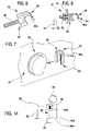
- FIG. 1is a diagram of a hydraulic circuit usable in a machine for intensive treatment according to the invention
- FIG. 2is a longitudinal section of a joint for a fluid transport line realized according to the invention.
- FIG. 3shows the joint of FIG. 2 applied to a fluid transport line
- FIG. 4is a second embodiment of a joint according to the present invention.
- FIG. 5is the joint of FIG. 4 applied to a fluid transport line
- FIG. 6is a support element which is applicable to a front surface of a dialysis machine, and is provided for removable fastening of the joint of FIG. 2 or 4 ;
- FIG. 7shows the support element of FIG. 6 applied to the front surface of a dialysis machine
- FIG. 8shows section VIII-VIII of FIG. 7 ;
- FIG. 9is a block diagram of the grounding of an extracorporeal circuit according to the present invention.
- FIG. 10is a more detailed version of the electrical diagram of FIG. 9 ;
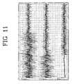
- FIG. 11is a recording of an electrocardiograph applied to a dialysis apparatus during laboratory tests, where the invention is not applied;
- FIG. 12is an ECG recording applied to the same apparatus as in FIG. 11 , where the invention is applied;
- FIG. 13compares two ECG recordings, taken during laboratory tests; in the first the conductive joint is not earthed, while in the second it is grounded with the interpositioning of a suitable safety grounding resistance;
- FIG. 14is a diagram of an infusion device made according to the present invention.
- the number 1denotes an apparatus for extracorporeal treatment of blood, in particular a dialysis machine for intensive treatment.
- a blood circuit 2removes the blood from a patient, through a vascular access of known type and not illustrated, and, via at least one withdrawal line (inlet line or arterial line) 2 a transports the blood, for example with continuous flow, to a blood treatment device 3 (or filtration unit, or dialyzer filter, or artificial kidney).
- a blood treatment device 3or filtration unit, or dialyzer filter, or artificial kidney.
- the bloodcrosses a first chamber (or blood chamber) of the blood treatment device 3 and, via a return line (or outlet line, or venous line) 2 b , the treated blood is returned to the internal vascular system of the patient.
- the withdrawal line 2 ais connected, immediately downstream of the blood withdrawal zone, to an auxiliary, pre-infusion line 4 .
- a source of secondary fluid 5(for example a container or bag), supplies the pre-infusion line 4 .
- the apparatuscomprises means for moving the fluid, in the illustrated example constituted by an auxiliary pre-infusion pump 6 (for example a peristaltic pump), which means for moving the fluid control the flow of secondary fluid injected directly into the blood via the pre-infusion line 4 .
- the source of secondary fluid 5can supply a suitable biological fluid to effect a pre-infusion, but can also supply an anti-coagulant.
- the bloodflows, in a blood circulation direction 7 , from the withdrawal line 2 a towards the filtration unit, and from the filtration unit flow via the return line 2 b back to the patient.
- a blood pressure sensor 8is predisposed immediately downstream of the auxiliary pre-infusion line 4 .
- the apparatuscomprises means for moving fluid, i.e. in the particular case at least one blood pump 9 for control and management of the blood flow in the blood circuit 2 .
- the blood pump 9is generally peristaltic.
- a device 10 for administering an anti-coagulantfor example a syringe containing appropriate doses of heparin, operates on the withdrawal line 2 a downstream of the blood pump 9 .
- the bloodpasses a further pressure sensor 11 which monitors the correct flow into the blood circuit 2 .
- the bloodenters the blood chamber of the treatment device 3 , where, through a semi-permeable membrane, the desired substance, molecular and fluidic exchanges occur.
- the treated bloodoutletting from the treatment device 3 , enters the return line 2 b , crossing first a gas separator device (generally air) 12 , predisposed to stop and expel any gassy substances or air bubbles present in the blood.
- the separator device 12is operatively associated with a pressure sensor, of known type and not illustrated, for controlling the pressure in the return line 2 b.
- the treated blood outletting from the separator device 12then crosses an air bubble sensor 13 which checks for absence of these dangerous formations internally of the treated blood.
- intercept element 14Located downstream of the air bubble sensor 13 an intercept element 14 is located, the function of which is to block, during any alarms, the blood flow towards the patient.
- the treated bloodDownstream of the intercept element 14 the treated blood is returned to the patient undergoing therapy.
- a fluid circuit 15is provided with at least one supply line 15 a of a treatment fluid (fresh dialysis fluid), which enters a second chamber (dialysis chamber) of the treatment device 3 , and a drainage line 15 b outletting from the second chamber 3 of the device.
- a treatment fluidfresh dialysis fluid
- At least one source of treatment fluid 16is connected to the supply line 15 a of the fluid circuit 15 (the source of the treatment fluid 16 can be constituted, for example, by at least one bag containing a dialysis liquid).
- the apparatus 1comprises means for moving the fluid along the supply line 15 a , including at least one supply pump 17 (in the illustrated embodiment a peristaltic pump), for controlling the flow of the treatment fluid coming from the source 16 and for defining a direction of circulation 18 .
- at least one supply pump 17in the illustrated embodiment a peristaltic pump
- a split 19which divides the fluid circuit 15 into an injection branch 20 and an infusion branch 21 .
- the infusion branch 21is connected to the return branch 2 b of the blood circuit 2 .
- the infusion branch 21enables a post-infusion directly into the blood circuit 2 , using the treatment fluid coming from the source 16 .
- the injection branch 20takes the treatment fluid directly to an inlet of the second chamber of the treatment device 3 .
- a selector switch 22is predisposed in proximity of the split 19 , and is for determining the percentage quantities of treatment fluid flow into the infusion branch 21 and into the injection branch 20 .
- the selector switch 22for example a cam switch or clamp switch, can assume at least a first operative configuration, in which the fluid is allowed to pass into the injection branch 20 , and prevents passage into the infusion branch 21 , and a second operative configuration, in which it allows passage into the infusion branch 21 and prevents passage into the injection branch 20 .
- the selector switch 22can modulate the quantities of fluid contemporaneously crossing one and the other branches 20 and 21 , and can determine, including by programming, the changes in the quantities of fluids which flow in one branch or the other according to predetermined times and treatments.
- the treatment fluid flowing in the injection branch 20enters the second chamber (dialysis chamber) of the treatment device 3 , which second chamber is separated from the first chamber (blood chamber) by the semi-permeable membrane which, as has already been mentioned, enables the correct substance exchanges between the blood and treatment fluid.
- the fluid outletting from the second chamber of the treatment device 3i.e. the discharge fluid, is transported by the drainage line 15 b , also known as the effluent line.
- a pressure sensor 23is predisposed for controlling the functioning of the drainage line 15 b.
- a drainage pump 24Downstream of the pressure sensor 23 are located means for moving the fluid, for example a drainage pump 24 , generally a peristaltic pump, able to control the flow in the drainage line 15 b of the fluid circuit 15 .
- the discharge fluidcrosses a blood leak detector 25 and is eliminated or directed into a container 26 for discharge fluid.
- the apparatuscomprises at least one further infusion line 27 which removes an infusion fluid from at least one auxiliary source 28 and, using means for moving fluid, usually a peristaltic infusion pump 29 which controls the flow, sends the fluid directly to the blood circuit 2 return line 2 b .
- the infusion liquidcan be introduced, as in the illustrated embodiment, directly into the gas separator device 12 .
- the infusion branch 21 of the fluid circuit 15 and the infusion line 27are provided with a common end tract 30 for injection into the blood circuit 2 .
- This end tract 30is located downstream of the infusion pump 29 with respect to an infusion direction 14 , and terminates directly in the separator device 12 .
- the infusion line 27comprises at least one pre-infusion branch 32 connected to the withdrawal line 2 a of the blood circuit 2 .
- a split 33which divides the infusion line 27 into the pre-infusion branch 32 and a post-infusion branch 34 .
- the pre-infusion branch 32transports the infusion fluid, taken from the container 28 , towards the withdrawal line 2 a of the blood circuit 2 , downstream of the blood pump 9 with respect to the circulation direction 7 .
- the post-infusion line 34is directly connected to the common end tract 30 .
- the infusion line 27is provided with a selector switch 35 , predisposed in proximity of the split 33 , for determining the percentage quantity of the flow of liquid to be sent into the post-infusion branch 34 and the pre-infusion branch 32 .
- the selector switch 35can assume at least a first operative configuration, in which it allows passage of fluid into the pre-infusion branch 32 and prevents passage of fluid into the post-infusion branch 34 , and at least a second operative configuration, in which it allows passage of fluid into the post-infusion branch 34 and prevents passage of fluid into the pre-infusion branch 32 .
- the switch 35can establish the percentage of fluid which must pass into each of the two branches 32 and 34 , and can if necessary vary the times according to the treatments to be performed.
- the apparatus 1comprises a disposable part, usable in general for a single treatment, and a fixed part, which is used a number of times for various treatments on various patients.
- the fixed partis in effect the machine for extracorporeal blood treatment.
- the machinecomprises, in general, a machine body which usually bears, on a front surface thereof, the various peristaltic pumps 6 , 9 , 17 , 24 and 29 , and also the various sensors, denoted by 8 , 11 , 13 , 23 and 25 , and the means for controlling flow, denoted by 14 , 22 and 35 , and an interfacing system with the operator, which generally comprises a display for entering and reading data.
- the machine bodyalso bears, internally, all of the electronic control circuitry, including a machine command unit.
- the disposable partcomprises the treatment device 3 and the blood circuit 2 ; in the illustrated embodiment, in which the apparatus serves to perform dialysis treatment of the intensive kind, the disposable part also comprises the dialysis circuit 15 .
- Substantially the machineintegrates all of the instrumentation and apparatus destined to be used more than once, in various treatments, on one or more patients.
- the disposable partsdestined to be used only once for each treatment to be performed on a patient, are borne on an integrated module, of known type and not illustrated, of the single-use type, applicable directly on the machine body.
- the operation of the apparatus 1includes a preliminary part, in which the disposable part is associated to the front surface of the machine body.
- the hydraulic circuitblood circuit 2 and dialysis circuit 15
- the blood treatment circuit 3are mounted on the machine in such a way that: the various peristaltic pumps engage the predisposed tracts of tubing (pump segments), which are generally U-shaped; all of the sensors are correctly engaged; and the containers of the various fluids are fluidly coupled to the respective fluid transport lines.
- the blood pump 9is started up, which starts circulation of the blood in the circuit.
- the machine for extracorporeal blood treatmentis automatically started up and controlled by the command unit.
- the apparatus for extracorporeal blood treatment described aboveis able to perform treatments, in particular intensive treatments, each of which comprises one or more of the following treatments, with predeterminable sequences: pure ultrafiltration, haemofiltration, haemodialysis, haemodiafiltration, plasma exchange.
- 36denotes a joint for fluid transport lines for medical use, which is made according to the object of the invention.
- the joint 36is predisposed along the drainage line 15 b immediately downstream of the blood treatment device 3 , that is, just after the outlet from the second chamber of the device 3 and before the drainage pump 24 .
- the joint 36is located between the pressure sensor 23 and the drainage pump 24 . This joint 36 will be described in more detail herein below.
- the joint 36is illustrated, in a first embodiment, in FIG. 2 .
- the joint 36is coupled to the drainage line 15 b.
- the joint 36comprises a tubular body 37 , substantially a sleeve-shape, having a cylindrical lateral external side and at two opposite ends two connecting zones 38 and 39 , each of which, has a cylindrical internal lateral surface for connecting with an end zone of a usual tubular element 40 of a fluid transport line for medical use.
- the connectiongives continuity to fluid passage.
- Each tubular element 40is a flexible elongate body, with elastically deformable walls, made of a dielectric plastic material, generally a thermoplastic resin, such as for example bio-compatible plasticized PVC.
- the joint 36is made in a single piece with a relatively small longitudinal extension having more rigid walls than the tubular elements 40 .
- the joint 36is made of a composite material including a mix of plastic material, generally a thermoplastic resin (for example the same material as the tubular elements 40 , in this embodiment bio-compatible plasticized PVC), with at least one additive to give it electrical conductivity.
- plastic materialgenerally a thermoplastic resin (for example the same material as the tubular elements 40 , in this embodiment bio-compatible plasticized PVC), with at least one additive to give it electrical conductivity.
- thermoplastic resinsalready dielectric, in suitable and known formulas, leads to obtaining a conductive material, though provided with relatively high electrical resistance.
- the additivecan be, for example, conductive carbon black, or another known product which, mixed with a thermoplastic resin, transforms the latter from being an insulator to being a conductor.
- the materialobtained from a mixture of a plastic material and a conductor additive, can be extruded by usual processes and apparatus used for PVC.
- the selected material for the conductive joint 36is CABELEC® 3895, constituted by a compound including carbon black, plasticized PVC, stabilizer and lubricant.
- the two connecting zones 38 and 39 of the jointare designed and structured to join the two tubular elements 40 solidly, one to another (even though axially distanced one from another), giving continuity to fluid passage.
- the two tubular elements 40joined together by the joint 36 , form a single conduit for the passage of a fluid.
- the tubular body 37made in a single piece, is produced by a plastic material pressing process.
- the tubular body 37is internally provided with at least one internal surface 41 , destined to come into contact with the transported fluid, situated in an intermediate axial zone of the tubular body 37 comprised between the two end connecting zones 38 and 39 .
- the external surface of the tubular body 37is destined to contact electrically with an element which is external of the fluid transport line, with the result that, via for example a grounded connection, the electrical currents present in the transported fluid transported in the fluid transport line can be dissipated.
- the external elementillustrated in figures from 6 to 8 , will be better described herein below.
- the tubular conductive joint 36has a greater electrical conductivity than the tubular elements 40 which are reciprocally joined by the joint 36 .
- the material of the tubular body 37is, as has been mentioned, is based on a thermoplastic material, which in itself is dielectric, and which is made electrically conductive thanks to the addition, in the body of the plastic material, of carbon black or another suitable additive for obtaining electrical conductivity.
- the joint 36can therefore be considered an electrically conductive element, differently to the plastic tubular elements 40 , which can be considered electric insulators.
- the conductive joint 36can be considered a high-resistance electrically-conductive element.
- the electrical impedance between the internal surface and the external surface of the tubular body 37can vary within a range between 40 K ⁇ and 10 M ⁇ .
- a substantial elimination of electrocardiograph disturbanceshas been verified, with the ECG connected up to a patient being subjected to extracorporeal treatment, using, in the apparatus, a conductive joint 36 having an electrical impedance variable between 200 K ⁇ and 2 M ⁇ .
- the material and conformation of the joint 36simply and economically obtain a good, stable, resistant and well-sealed joint, between the joint 36 and the tubular elements 40 which it joins.
- the joint unionpermanently stable and unbreakable, can be obtained, during assembly, by a process of known type and already in use, for example, for solid connections by gluing of PVC tubes for medical products having corresponding plastic connectors.
- the procedureinvolves insertion of the end zones of the tubular elements 40 inside the connecting zones 38 and 39 of the joint 36 , with a preliminary spreading on at least one of the coupling surfaces of a certain amount of a suitable glue, for example a cyclo-hexanone-based glue.
- the conductive joint 36 ′is constituted by a tubular body 37 ′, made in a single piece, which internally comprises at least one first axial stop element 42 , operatively associated to an end zone of a first tubular element 40 ′, for limiting an axial insertion of the first tubular element within the tubular body.
- the tubular body 37 ′internally comprises a second axial stop element 43 , axially distanced from the first axial stop element 42 , and operatively associated to an end zone of the second tubular element 40 ′′, for limiting an axial insertion of the second tubular element inside the tubular body 37 ′, in an opposite direction with respect to the axial insertion of the first tubular element 40 ′.
- the tubular body 37 ′has an intermediate zone 41 ′ comprised axially between the two end connecting zones 38 ′ and 39 ′, the internal diameter of which is smaller than the internal diameter of the connecting zones.
- the intermediate zone 41 ′offers an inwardly-directed annular recess, axially delimited by two abutments, which form the stop elements 42 and 43 which limit insertion of the end zones of the tubular elements 40 ′ and 40 ′′.
- the elements 42 and 43have the function of preventing total covering of the internal surface of the tubular body 37 ′ by the tubular elements 40 ′ and 40 ′′, so that a free intermediate zone 41 ′ on the internal surface remains free, i.e. not covered by the end zones of the tubular elements 40 ′ and 40 ′′, and in direct contact with the fluid which flows along the fluid transport line. This direct contact allows for dispersion to the outside of any electrostatic charges in the fluid.
- the drainage line 15 b of the apparatus 1is an example of a fluid transport line, for medical use, made according to the invention.
- the fluid transport linecomprises at least a first part and a second part, both in contact with the transported fluid, in which the second part is made of a material having a greater electrical conductivity than the material the first part is made of.
- the second part of the linecan comprise, as in the embodiment described herein, a conductive joint 36 or 36 ′ like those first described, while the first part can comprise the tubular elements 40 , 40 ′, 40 ′′ described above.
- the second part of lineis also predisposed for galvanic connection to an element which is external of the line, as will be better explained herein below.
- the conductive second part of the lineexhibits at least one internal surface destined to contact with the transported fluid, and at least one external surface predisposed to be associated, in electrical contact, with a support element which is external of the line.
- the first partis made of a thermoplastic material which is elastically deformable and dielectric
- the second partis made of a material composed of a mix of thermoplastic, dielectric material with the addition of at least one additive which gives the mixture a certain electrical conductivity.
- the additivealso has the property of giving greater rigidity to the mixture.
- the second part of the electrically conductive lineis situated, with reference to the fluid transport direction, upstream of a pump segment of the line.
- the pump segmentis a tract of line, normally U-shaped and elastically deformable, which is operatively associated to a normally-peristaltic pump, for circulation of the transported fluid.
- the second part of electrically-conductive linecan be located, in other embodiments which are not illustrated, in any other point of the hydraulic circuit of FIG. 1 , either in the fluid circuit 15 (or dialysis circuit) or in the blood circuit 2 .
- the location on the drainage line 15 b , immediately downstream of the treatment device 3 ,has the advantage of ensuring an efficient electrical connection between the second part of line (the joint 36 ) and the blood circuit 2 , without resorting to direct contact between the blood and the second part of electrically-conductive line.
- the treatment device 3or dialyzer filter, does not constitute a barrier to electrical communication between the blood circuit 2 and the fluid circuit 15 .
- An apparatus for extracorporeal blood treatmentpredisposed for cooperating with one of the above-cited hydraulic circuits, comprises at least one support element 44 predisposed to receive, with a mechanical engagement and in electrical contact, the above-mentioned second, electrically-conductive part of line (joint 36 or 36 ′).
- the support element 44is solidly connected to a front panel 45 of the machine for extracorporeal blood treatment.
- An embodiment of this support element 44is illustrated in FIG. 6 , while FIGS. 7 and 8 show the same support element 44 applied to the front panel 45 of the machine (in FIG. 7 the blood leak detector 25 can also be seen, located by the side of the support element 44 ).
- the support element 44comprises at least one electrically-conductive first part 46 , made, for example, of metal, fixed to the front panel 45 of the machine by, for example, a screw connection 47 .
- the conductive first part 46can comprise a threaded stalk 48 for the screw connection with the front panel 45 .
- the support element 44further comprises a second part 49 , also dielectric and made of a plastic material, provided with a gripping organ 49 a for removably fixing the fluid transport line to the conductive second part (the joint).
- the first and second parts 46 and 49 of the support elementare solidly constrained one to another, for example by a screw connection (not illustrated).
- the gripping organ 49 acomprises, for example, a fastening, in the guise of an elastically deformable hook, which affords a seating in which the conductive joint 36 or 36 ′ can be inserted and held tight in position.
- the joint 36 or 36 ′can be inserted and and removed manually from the seating.
- the apparatus 1further comprises a galvanic connection 50 which connects the support element 44 with an external mass, for external dissipation of any electrical charges present in the fluids, corporeal and/or medical, transported in the extracorporeal hydraulic circuit.
- the galvanic connection 50terminates in the conductive first part 46 of the support element 44 .
- the galvanic connection 50is a true and proper earth for the joint 36 , comprising at least one electrical earthing cable which connects the conductive first part of the support element, which is in contact with the above-mentioned conductive second part of line (joint 36 or 36 ′), with the machine body, which machine body is in turn normally provided with its own grounding.
- the galvanic connection 50also comprises at least one safety electrical impedance 51 , of a predetermined entity, predisposed along the grounding cable between the support element 44 and the machine body.
- This safety impedance 51guarantees the machine's electrical insulation, as required by the standards, together with the impedance value of the conductive joint 36 or 36 ′.
- the entity of the electrical impedance 51can be, for example, above about 0.1 M ⁇ . It has been found that an efficient elimination of ECG artefacts (caused by the action of the peristaltic pumps) is also achieved with a safety impedance 51 of above about 1.0 M ⁇ .
- a plurality of electrical impedancescould be predisposed in parallel along the galvanic connection, with the aim of reducing the power dissipated.
- the galvanic connection to earthcan comprise, for example, an electronic board having: one or more impedances having predefined characteristics, at least a first contact for connecting to the conductive part 46 of the support element, and at least a second contact for connecting to the earthing cable.
- FIG. 9shows a block diagram of the electrical earthing system of the hydraulic circuit of the apparatus 1 .
- 52denotes, in its entirety, the disposable part of the dialysis apparatus, which is provided with at least one conductive element in contact with at least one fluid which is transported along at least one tract of the hydraulic circuit of the apparatus.
- 53denotes, in its entirety, the fixed part of the dialysis apparatus which comprises the support element 44 , which, as mentioned, functions as a mechanical fastening and as an electrical contact for the conductive element of the disposable part.
- 54denotes the machine body 54 of the machine, which is equipped with it own galvanic earthing connection 55 , of known type.
- 56denotes the electrical connections which connect up the various above-mentioned elements among themselves.
- FIG. 10is a more detailed electrical diagram: 57 denotes the electric supply, 58 the machine command unit, 59 the operator interface display, 60 the entirety of the peristaltic pumps for circulation of the various fluids (corporeal and medical), 61 the entirety of the control organs for regulation of the various fluid transport lines (clamps, valves, selectors etc.), 62 the totality of the sensors (pressure, blood, air-bubble, any fluid-container weighing sensors there might be, and so on).
- the conductive joint 36 or 36 ′is pressure-fitted, simply and manually, in the seating constituted by the elastic fastening of the support element 44 .
- Figures from 11 to 13show the results of some laboratory tests performed to evaluate the effectiveness of the solution proposed in eliminating the ECG artefacts due to the rotation of the peristaltic pumps.
- an apparatuscomprising a machine for dialysis treatment was used, such as the one illustrated in FIG. 1 , fitted with a disposable integrated module which includes both the blood circuit and the dialysis circuit, and also the dialyzer filter.
- the dialysis circuit used in the testsis the fluid circuit 15 of FIG. 1 , minus branches 21 and 34 .
- a saline solution (9 g/l)was circulated in the blood circuit, taken from a container and returned to the same container; blood pump flow rate was fixed at 180 ml/min.
- terminals L47 K ⁇
- R380 K ⁇
- F47 K ⁇
- N47 K ⁇
- Terminal Lwas unbalanced by introducing, after the resistance, a 400 pF, condenser towards the ground.
- the slight unbalance of the impedance of electrode Ltransforms the common mode voltage produced by the rotation of the pump into a differential signal which is recorded by the ECG on I.
- the conductivity of the conductive joint 36was measured.
- the jointwas filled with saline solution (9 g/l) and the electric resistance between the external surface of the joint and the liquid inside was measured.
- the joint used in the testshad a resistance which varied between 200 K ⁇ and 2 M ⁇ .
- FIG. 11which shows the recording obtained with the conductive joint not grounded, evidences the disturbance produced by the pump rotation (paper speed 25 mm/sec, disturbance synchronous with movement of pump at about 6 c/s). There was disturbance on all cutouts with the exception of no. III, where disturbance is rejected and the impedances of the relative electrodes were exactly balanced.
- the automatic interpretation of the tracinggives abnormal ECG with atrial fibrillation, abnormal right axial deviation, unspecific intraventricular blockage.
- FIG. 12shows the ECG recording of the same test after the conductive joint, positioned on the effluent line immediately downstream of the dialyzer filter, has been galvanically connected to ground.
- the ground connectionconsists in connecting the joint by an electric cable to the machine body which in turn is grounded through the supply circuit.
- FIG. 13compares two test recordings.
- the top tracerelates to a situation in which the conductive joint was not grounded: the automatic interpretation gives abnormal ECG with atrial flutter, epicardiac lesions, possibility of frontal infarct.
- the bottom tracerelates to a situation in which the joint is grounded and in which, along the electric connecting cable between the joint and the body of the machine, a 1.2 M ⁇ resistance has been positioned.
- the automatic responsedescribes an atypical ECG, but none of the negative interpretations given for the top tract.
- the test resultis a demonstration of the elimination of the ECG interference, even when a resistance is put in the ground connection which resistance is sufficient to conserve the requisite of electrical insulation of the machine.
- the fluid transport line for medical usecomprising the conductive joint 36 or 36 ′, as above described, can be used in the fields various typologies of medical apparatus where ECG interference is a problem.
- the descriptionrelates to an apparatus for intensive treatment of acute renal insufficiency: it would be possible however to use the invention in other medical apparatus, such as for example dialysis apparatus for chronic renal insufficiency.
- the devicecomprises:
- the devicecan further comprises a safety impedance 68 , predisposed along the galvanic connection 67 , having the function of guaranteeing that the electrical insulation for the patient undergoing the infusion treatment is in conformity with existing safety standards, and a mechanical fastening and electrical contact element, denoted by 69 , to which the conductive joint 66 is applied, for example removably.
- a safety impedance 68predisposed along the galvanic connection 67 , having the function of guaranteeing that the electrical insulation for the patient undergoing the infusion treatment is in conformity with existing safety standards
- a mechanical fastening and electrical contact elementdenoted by 69
- the infusion line 64can be connected, directly to a vascular access of the patient, or indirectly to the patient, via an extracorporeal circuit.
- the material the conductive joint 66 is made ofis a polymer which has been made conductive thanks to addition and mixing of carbon black or another known additive. As can be observed, in this case too the conductive joint 66 is located upstream of the peristaltic pump 65 , with reference to the infusion fluid circulation direction.
- the electrical contact element 69 destined to engage with the conductive joint 66which can be once more, for example, an elastic fastening, can be solidly constrained to the pump body of the peristaltic pump 65 .
- the particular location, before the fluid circulation pump, of the conductive elementguarantees reciprocal contact, constantly and in all operative situations, between the transported fluid and the conductive element.
- the transport fluid which is galvanically connected to the outsideis, in the first case ( FIG. 1 ) the discharge fluid in the drainage line of a dialyzer filter, and in the second case ( FIG. 14 ) the infusion fluid circulating along an infusion line, simple or cooperating with an extracorporeal blood circuit.
- Other transport fluidscould, however, be galvanically connected to the outside, such as for example blood, circulating in the withdrawal line or the return line of an extracorporeal circuit, or fresh dialyzing fluid, circulating in the supply line of the dialysis chamber of a dialyzer filter, or the pre-infusion or post-infusion liquid of a dialysis circuit.
Landscapes
- Health & Medical Sciences (AREA)
- Heart & Thoracic Surgery (AREA)
- Hematology (AREA)
- Anesthesiology (AREA)
- Biomedical Technology (AREA)
- Engineering & Computer Science (AREA)
- Life Sciences & Earth Sciences (AREA)
- Animal Behavior & Ethology (AREA)
- General Health & Medical Sciences (AREA)
- Public Health (AREA)
- Veterinary Medicine (AREA)
- Vascular Medicine (AREA)
- Pulmonology (AREA)
- External Artificial Organs (AREA)
Abstract
Description
- a
source 63 of an infusion liquid; - an
infusion line 64 having a first end, aninlet 64a, connected to thesource 63 and a second end, anoutlet 64b, which is placed in fluid communication, either directly or indirectly, with the vascular system of a patient; - an
infusion pump 65, for example a peristaltic pump, operatively associated to theinfusion line 64 for circulating the infusion liquid; - a conductive joint66, made like the joint36 or36′, predisposed along the
infusion line 64 upstream of thepump 65; - a
galvanic connection 67 for connecting the conductive joint66 with an external mass (for example the ground).
- a
Claims (21)
Priority Applications (2)
| Application Number | Priority Date | Filing Date | Title |
|---|---|---|---|
| US10/859,546US7291123B2 (en) | 2003-06-04 | 2004-06-03 | Joint for fluid transport lines for medical use |
| US11/898,014US7785284B2 (en) | 2003-06-04 | 2007-09-07 | Joint for fluid transport lines for medical use |
Applications Claiming Priority (5)
| Application Number | Priority Date | Filing Date | Title |
|---|---|---|---|
| ITMO2003A0165 | 2003-06-04 | ||
| ITMO2003A000165 | 2003-06-04 | ||
| IT000165AITMO20030165A1 (en) | 2003-06-04 | 2003-06-04 | JOINT FOR FLUID TRANSPORT LINES FOR MEDICAL USE. |
| US51132703P | 2003-10-16 | 2003-10-16 | |
| US10/859,546US7291123B2 (en) | 2003-06-04 | 2004-06-03 | Joint for fluid transport lines for medical use |
Related Child Applications (1)
| Application Number | Title | Priority Date | Filing Date |
|---|---|---|---|
| US11/898,014DivisionUS7785284B2 (en) | 2003-06-04 | 2007-09-07 | Joint for fluid transport lines for medical use |
Publications (2)
| Publication Number | Publication Date |
|---|---|
| US20050010157A1 US20050010157A1 (en) | 2005-01-13 |
| US7291123B2true US7291123B2 (en) | 2007-11-06 |
Family
ID=33568281
Family Applications (2)
| Application Number | Title | Priority Date | Filing Date |
|---|---|---|---|
| US10/859,546Expired - LifetimeUS7291123B2 (en) | 2003-06-04 | 2004-06-03 | Joint for fluid transport lines for medical use |
| US11/898,014Expired - LifetimeUS7785284B2 (en) | 2003-06-04 | 2007-09-07 | Joint for fluid transport lines for medical use |
Family Applications After (1)
| Application Number | Title | Priority Date | Filing Date |
|---|---|---|---|
| US11/898,014Expired - LifetimeUS7785284B2 (en) | 2003-06-04 | 2007-09-07 | Joint for fluid transport lines for medical use |
Country Status (1)
| Country | Link |
|---|---|
| US (2) | US7291123B2 (en) |
Cited By (35)
| Publication number | Priority date | Publication date | Assignee | Title |
|---|---|---|---|---|
| US20090001718A1 (en)* | 2006-03-02 | 2009-01-01 | Gambro Lundia Ab | Hydraulic Connector and a Hydraulic Circuit Incorporating the Connector |
| US8512553B2 (en) | 2007-07-05 | 2013-08-20 | Baxter International Inc. | Extracorporeal dialysis ready peritoneal dialysis machine |
| US8529490B2 (en) | 2002-04-10 | 2013-09-10 | Baxter International Inc. | Systems and methods for dialysis access disconnection |
| US8708946B2 (en) | 2002-04-10 | 2014-04-29 | Baxter International Inc. | Access disconnection systems using conductive contacts |
| US8858185B2 (en) | 2010-06-23 | 2014-10-14 | Hospira, Inc. | Fluid flow rate compensation system using an integrated conductivity sensor to monitor tubing changes |
| US8920356B2 (en) | 2002-04-10 | 2014-12-30 | Baxter International Inc. | Conductive polymer materials and applications thereof including monitoring and providing effective therapy |
| US9328969B2 (en) | 2011-10-07 | 2016-05-03 | Outset Medical, Inc. | Heat exchange fluid purification for dialysis system |
| US9402945B2 (en) | 2014-04-29 | 2016-08-02 | Outset Medical, Inc. | Dialysis system and methods |
| US9440017B2 (en) | 2013-03-14 | 2016-09-13 | Baxter International Inc. | System and method for performing alternative and sequential blood and peritoneal dialysis modalities |
| US9545469B2 (en) | 2009-12-05 | 2017-01-17 | Outset Medical, Inc. | Dialysis system with ultrafiltration control |
| US10022498B2 (en) | 2011-12-16 | 2018-07-17 | Icu Medical, Inc. | System for monitoring and delivering medication to a patient and method of using the same to minimize the risks associated with automated therapy |
| US10155082B2 (en) | 2002-04-10 | 2018-12-18 | Baxter International Inc. | Enhanced signal detection for access disconnection systems |
| US10166328B2 (en) | 2013-05-29 | 2019-01-01 | Icu Medical, Inc. | Infusion system which utilizes one or more sensors and additional information to make an air determination regarding the infusion system |
| US10342917B2 (en) | 2014-02-28 | 2019-07-09 | Icu Medical, Inc. | Infusion system and method which utilizes dual wavelength optical air-in-line detection |
| US10430761B2 (en) | 2011-08-19 | 2019-10-01 | Icu Medical, Inc. | Systems and methods for a graphical interface including a graphical representation of medical data |
| US10463788B2 (en) | 2012-07-31 | 2019-11-05 | Icu Medical, Inc. | Patient care system for critical medications |
| US10578474B2 (en) | 2012-03-30 | 2020-03-03 | Icu Medical, Inc. | Air detection system and method for detecting air in a pump of an infusion system |
| US10596316B2 (en) | 2013-05-29 | 2020-03-24 | Icu Medical, Inc. | Infusion system and method of use which prevents over-saturation of an analog-to-digital converter |
| US10635784B2 (en) | 2007-12-18 | 2020-04-28 | Icu Medical, Inc. | User interface improvements for medical devices |
| US10656894B2 (en) | 2017-12-27 | 2020-05-19 | Icu Medical, Inc. | Synchronized display of screen content on networked devices |
| US10850024B2 (en) | 2015-03-02 | 2020-12-01 | Icu Medical, Inc. | Infusion system, device, and method having advanced infusion features |
| US10874793B2 (en) | 2013-05-24 | 2020-12-29 | Icu Medical, Inc. | Multi-sensor infusion system for detecting air or an occlusion in the infusion system |
| US11135360B1 (en) | 2020-12-07 | 2021-10-05 | Icu Medical, Inc. | Concurrent infusion with common line auto flush |
| US11246985B2 (en) | 2016-05-13 | 2022-02-15 | Icu Medical, Inc. | Infusion pump system and method with common line auto flush |
| US11278671B2 (en) | 2019-12-04 | 2022-03-22 | Icu Medical, Inc. | Infusion pump with safety sequence keypad |
| US11324888B2 (en) | 2016-06-10 | 2022-05-10 | Icu Medical, Inc. | Acoustic flow sensor for continuous medication flow measurements and feedback control of infusion |
| US11344673B2 (en) | 2014-05-29 | 2022-05-31 | Icu Medical, Inc. | Infusion system and pump with configurable closed loop delivery rate catch-up |
| US11344668B2 (en) | 2014-12-19 | 2022-05-31 | Icu Medical, Inc. | Infusion system with concurrent TPN/insulin infusion |
| US11534537B2 (en) | 2016-08-19 | 2022-12-27 | Outset Medical, Inc. | Peritoneal dialysis system and methods |
| US11724013B2 (en) | 2010-06-07 | 2023-08-15 | Outset Medical, Inc. | Fluid purification system |
| US11883361B2 (en) | 2020-07-21 | 2024-01-30 | Icu Medical, Inc. | Fluid transfer devices and methods of use |
| US12201762B2 (en) | 2018-08-23 | 2025-01-21 | Outset Medical, Inc. | Dialysis system and methods |
| US12350233B2 (en) | 2021-12-10 | 2025-07-08 | Icu Medical, Inc. | Medical fluid compounding systems with coordinated flow control |
| US12390565B2 (en) | 2019-04-30 | 2025-08-19 | Outset Medical, Inc. | Dialysis systems and methods |
| USD1091564S1 (en) | 2021-10-13 | 2025-09-02 | Icu Medical, Inc. | Display screen or portion thereof with graphical user interface for a medical device |
Families Citing this family (14)
| Publication number | Priority date | Publication date | Assignee | Title |
|---|---|---|---|---|
| US7530962B2 (en)* | 2005-06-16 | 2009-05-12 | Edward Allan Ross | Method for detecting the disconnection of an extracorporeal device using a patient's endogenous electrical voltages |
| FR2909003B1 (en)* | 2006-11-24 | 2009-10-09 | Oscar Maier | DEVICE FOR DEPARASITING MEDICAL EQUIPMENT PROVIDING CIRCULATION OF BLOOD OR SOLUTE AND DISRUPTING TRACES COLLECTED USING ELECTRODES ON PATIENTS (ECG, EMG, EEG ...) |
| US8376978B2 (en)* | 2007-02-09 | 2013-02-19 | Baxter International Inc. | Optical access disconnection systems and methods |
| US10463778B2 (en) | 2007-02-09 | 2019-11-05 | Baxter International Inc. | Blood treatment machine having electrical heartbeat analysis |
| US8152751B2 (en) | 2007-02-09 | 2012-04-10 | Baxter International Inc. | Acoustic access disconnection systems and methods |
| ITMI20072397A1 (en)* | 2007-12-20 | 2009-06-21 | Gambro Lundia Ab | MEDICAL EQUIPMENT FOR EXTRA-REPAIR TREATMENT |
| AU2008354310B2 (en) | 2008-04-01 | 2014-02-20 | Gambro Lundia Ab | An apparatus and a method for monitoring a vascular access |
| US8114043B2 (en) | 2008-07-25 | 2012-02-14 | Baxter International Inc. | Electromagnetic induction access disconnect sensor |
| US9259351B2 (en) | 2010-03-29 | 2016-02-16 | Johnson & Johnson Vision Care, Inc. | Punctal plugs |
| US8690860B2 (en)* | 2011-01-10 | 2014-04-08 | CareFusion, Inc. | Intravenous infusion tubing fitment and set |
| US8777931B2 (en) | 2011-08-19 | 2014-07-15 | Alcon Research, Ltd. | Retractable luer lock fittings |
| US10265025B2 (en) | 2013-06-25 | 2019-04-23 | Biosense Webster (Israel) Ltd. | Electrocardiogram noise reduction |
| US9504522B2 (en) | 2013-06-25 | 2016-11-29 | Biosense Webster (Israel) Ltd. | Electrocardiogram noise reduction |
| PL3590559T3 (en) | 2018-07-02 | 2023-04-17 | Gambro Lundia Ab | Medical device for introduction of a fluid into the blood circulation system of a patient and method for controlling leakage currents in a medical device provided or combined with a warming unit |
Citations (26)
| Publication number | Priority date | Publication date | Assignee | Title |
|---|---|---|---|---|
| US3070132A (en) | 1960-04-06 | 1962-12-25 | David S Sheridan | Non-sparking medico-surgical tubes |
| GB1033971A (en) | 1963-04-09 | 1966-06-22 | Willy Ruesch | Connecting tube for catheters and surgical instruments |
| US3580983A (en) | 1969-12-03 | 1971-05-25 | Nat Catheter Corp | Conductive line tube |
| US3914002A (en) | 1974-04-17 | 1975-10-21 | Sherwood Medical Ind Inc | Conductive tubing and method of making same |
| US4012103A (en) | 1975-09-03 | 1977-03-15 | Medtronic, Inc. | Antishock, insulated connector |
| US4027659A (en) | 1975-11-21 | 1977-06-07 | Krandex Corporation | Radiographic opaque and conductive stripped medical tubes |
| US4059847A (en) | 1976-09-01 | 1977-11-22 | Dayco Corporation | Hose having an electrically conductive layer for dissipating static electricity and method of making same |
| US4215384A (en) | 1978-03-09 | 1980-07-29 | Dayco Corporation | Hose construction with electrical conductor for dissipating static electricity and method of making same |
| FR2547504A1 (en) | 1983-05-04 | 1984-12-21 | Palemon Jean Georges | Disposable anti-pruritus device mounted on haemodialyser generator |
| US4537200A (en)* | 1983-07-07 | 1985-08-27 | The Board Of Trustees Of The Leland Stanford Junior University | ECG enhancement by adaptive cancellation of electrosurgical interference |
| US4640563A (en)* | 1985-06-10 | 1987-02-03 | The Leblanc Corporation | Universal clasp structure for external electrode probes |
| US4675780A (en) | 1985-08-26 | 1987-06-23 | The Gates Rubber Company | Conductive fiber hose |
| EP0488410A1 (en) | 1990-11-30 | 1992-06-03 | Terumo Kabushiki Kaisha | Electrocardiograph system |
| US5127907A (en) | 1990-12-06 | 1992-07-07 | Abbott Laboratories | System for eliminating or reducing static electricity in infusion pumping systems |
| EP0542140A2 (en) | 1991-11-15 | 1993-05-19 | Fresenius AG | Tube arrangement for use in a blood circuit |
| US5220920A (en)* | 1991-11-08 | 1993-06-22 | Via Medical Corporation | Electrochemical measurement system having interference reduction circuit |
| US5305760A (en)* | 1992-02-07 | 1994-04-26 | Interflo Medical Inc. | Method for rejecting electrical interference from physiological measurements |
| US5431638A (en) | 1991-04-10 | 1995-07-11 | United States Surgical Corporation | Energy dissipation device |
| US5618309A (en) | 1992-05-19 | 1997-04-08 | Green; David T. | Cannula assembly having conductive cannula |
| US6102897A (en) | 1996-11-19 | 2000-08-15 | Lang; Volker | Microvalve |
| WO2001047581A1 (en)* | 1999-12-28 | 2001-07-05 | Hospal Ag | Method and device for monitoring the access to the cardiovascular system of a patient |
| US6287484B1 (en) | 1992-11-12 | 2001-09-11 | Robert Hausslein | Iontophoretic material |
| WO2002013689A2 (en)* | 2000-08-15 | 2002-02-21 | The Regents Of The University Of California | Method and apparatus for reducing contamination of an electrical signal |
| EP1424637A1 (en)* | 2002-11-29 | 2004-06-02 | Instrumentarium Corporation | Artifact removal from an electric signal |
| US20040225225A1 (en)* | 2001-01-09 | 2004-11-11 | Naumov Valery Arkadievich | Method and device for registering and processing plethysmograms |
| WO2004108206A1 (en)* | 2003-06-04 | 2004-12-16 | Gambro Lundia Ab | A joint for fluid transport lines for medical use |
Family Cites Families (6)
| Publication number | Priority date | Publication date | Assignee | Title |
|---|---|---|---|---|
| US4983456A (en)* | 1982-03-16 | 1991-01-08 | American Cyanamid | Compositions convertible to reinforced conductive components and articles incorporating same |
| US5220290A (en)* | 1991-06-03 | 1993-06-15 | Motorola, Inc. | Power amplifier |
| US5754388A (en)* | 1996-06-14 | 1998-05-19 | Schmidt; Ernest A. | Electrical charge dissipation device |
| US6497841B1 (en)* | 1997-07-22 | 2002-12-24 | Medtronic, Inc. | Prevention of electrical discharges in polymeric heat exchangers |
| ITTO20010037U1 (en)* | 2001-03-02 | 2002-09-02 | Gambro Dasco Spa | CONNECTION OF A BLOOD CIRCULATION CIRCUIT IN A DIDIALYSIS MACHINE. |
| JP2003047653A (en) | 2001-05-28 | 2003-02-18 | Terumo Corp | Medical composite material, medical tubular body and medical instrument |
- 2004
- 2004-06-03USUS10/859,546patent/US7291123B2/ennot_activeExpired - Lifetime
- 2007
- 2007-09-07USUS11/898,014patent/US7785284B2/ennot_activeExpired - Lifetime
Patent Citations (29)
| Publication number | Priority date | Publication date | Assignee | Title |
|---|---|---|---|---|
| US3070132A (en) | 1960-04-06 | 1962-12-25 | David S Sheridan | Non-sparking medico-surgical tubes |
| GB1033971A (en) | 1963-04-09 | 1966-06-22 | Willy Ruesch | Connecting tube for catheters and surgical instruments |
| US3580983A (en) | 1969-12-03 | 1971-05-25 | Nat Catheter Corp | Conductive line tube |
| US3914002A (en) | 1974-04-17 | 1975-10-21 | Sherwood Medical Ind Inc | Conductive tubing and method of making same |
| US4012103A (en) | 1975-09-03 | 1977-03-15 | Medtronic, Inc. | Antishock, insulated connector |
| US4027659A (en) | 1975-11-21 | 1977-06-07 | Krandex Corporation | Radiographic opaque and conductive stripped medical tubes |
| US4059847A (en) | 1976-09-01 | 1977-11-22 | Dayco Corporation | Hose having an electrically conductive layer for dissipating static electricity and method of making same |
| US4215384A (en) | 1978-03-09 | 1980-07-29 | Dayco Corporation | Hose construction with electrical conductor for dissipating static electricity and method of making same |
| FR2547504A1 (en) | 1983-05-04 | 1984-12-21 | Palemon Jean Georges | Disposable anti-pruritus device mounted on haemodialyser generator |
| US4537200A (en)* | 1983-07-07 | 1985-08-27 | The Board Of Trustees Of The Leland Stanford Junior University | ECG enhancement by adaptive cancellation of electrosurgical interference |
| US4640563A (en)* | 1985-06-10 | 1987-02-03 | The Leblanc Corporation | Universal clasp structure for external electrode probes |
| US4675780A (en) | 1985-08-26 | 1987-06-23 | The Gates Rubber Company | Conductive fiber hose |
| EP0488410A1 (en) | 1990-11-30 | 1992-06-03 | Terumo Kabushiki Kaisha | Electrocardiograph system |
| US5284151A (en) | 1990-11-30 | 1994-02-08 | Terumo Kabushiki Kaisha | Electrocardiograph system |
| US5127907A (en) | 1990-12-06 | 1992-07-07 | Abbott Laboratories | System for eliminating or reducing static electricity in infusion pumping systems |
| US5431638A (en) | 1991-04-10 | 1995-07-11 | United States Surgical Corporation | Energy dissipation device |
| US5220920A (en)* | 1991-11-08 | 1993-06-22 | Via Medical Corporation | Electrochemical measurement system having interference reduction circuit |
| EP0542140A2 (en) | 1991-11-15 | 1993-05-19 | Fresenius AG | Tube arrangement for use in a blood circuit |
| EP0542140A3 (en) | 1991-11-15 | 1993-07-21 | Fresenius Ag | Tube arrangement for use in a blood circuit |
| US5305760A (en)* | 1992-02-07 | 1994-04-26 | Interflo Medical Inc. | Method for rejecting electrical interference from physiological measurements |
| US5618309A (en) | 1992-05-19 | 1997-04-08 | Green; David T. | Cannula assembly having conductive cannula |
| US6287484B1 (en) | 1992-11-12 | 2001-09-11 | Robert Hausslein | Iontophoretic material |
| US6102897A (en) | 1996-11-19 | 2000-08-15 | Lang; Volker | Microvalve |
| WO2001047581A1 (en)* | 1999-12-28 | 2001-07-05 | Hospal Ag | Method and device for monitoring the access to the cardiovascular system of a patient |
| US20030036719A1 (en) | 1999-12-28 | 2003-02-20 | Sara Giacomelli | Method and device for monitoring the access to the cardiovascular system of a patient |
| WO2002013689A2 (en)* | 2000-08-15 | 2002-02-21 | The Regents Of The University Of California | Method and apparatus for reducing contamination of an electrical signal |
| US20040225225A1 (en)* | 2001-01-09 | 2004-11-11 | Naumov Valery Arkadievich | Method and device for registering and processing plethysmograms |
| EP1424637A1 (en)* | 2002-11-29 | 2004-06-02 | Instrumentarium Corporation | Artifact removal from an electric signal |
| WO2004108206A1 (en)* | 2003-06-04 | 2004-12-16 | Gambro Lundia Ab | A joint for fluid transport lines for medical use |
Cited By (70)
| Publication number | Priority date | Publication date | Assignee | Title |
|---|---|---|---|---|
| US8920356B2 (en) | 2002-04-10 | 2014-12-30 | Baxter International Inc. | Conductive polymer materials and applications thereof including monitoring and providing effective therapy |
| US8529490B2 (en) | 2002-04-10 | 2013-09-10 | Baxter International Inc. | Systems and methods for dialysis access disconnection |
| US8708946B2 (en) | 2002-04-10 | 2014-04-29 | Baxter International Inc. | Access disconnection systems using conductive contacts |
| US8801646B2 (en) | 2002-04-10 | 2014-08-12 | Baxter International Inc. | Access disconnection systems with arterial and venous line conductive pathway |
| US10155082B2 (en) | 2002-04-10 | 2018-12-18 | Baxter International Inc. | Enhanced signal detection for access disconnection systems |
| US7914049B2 (en)* | 2006-03-02 | 2011-03-29 | Gambro Lundia Ab | Hydraulic connector and a hydraulic circuit incorporating the connector |
| US20090001718A1 (en)* | 2006-03-02 | 2009-01-01 | Gambro Lundia Ab | Hydraulic Connector and a Hydraulic Circuit Incorporating the Connector |
| US11672895B2 (en) | 2007-07-05 | 2023-06-13 | Baxter International Inc. | Method for peritoneal dialysis and extracorporeal blood treatments |
| US11045595B2 (en) | 2007-07-05 | 2021-06-29 | Baxter International Inc. | System for peritoneal dialysis and extracorporeal blood treatments |
| US8512553B2 (en) | 2007-07-05 | 2013-08-20 | Baxter International Inc. | Extracorporeal dialysis ready peritoneal dialysis machine |
| US10441703B2 (en) | 2007-07-05 | 2019-10-15 | Baxter International Inc. | Weight controlled and/or sorbent hybrid blood and peritoneal dialysis treatment systems and methods |
| US10434237B2 (en) | 2007-07-05 | 2019-10-08 | Baxter International Inc. | Hybrid blood and peritoneal dialysis treatment systems and methods |
| US9227003B2 (en) | 2007-07-05 | 2016-01-05 | Baxter International Inc. | Hybrid blood and peritoneal dialysis treatment systems and methods |
| US9744284B2 (en) | 2007-07-05 | 2017-08-29 | Baxter International Inc. | Hybrid blood and peritoneal dialysis treatment systems and methods |
| US10635784B2 (en) | 2007-12-18 | 2020-04-28 | Icu Medical, Inc. | User interface improvements for medical devices |
| US9545469B2 (en) | 2009-12-05 | 2017-01-17 | Outset Medical, Inc. | Dialysis system with ultrafiltration control |
| US11724013B2 (en) | 2010-06-07 | 2023-08-15 | Outset Medical, Inc. | Fluid purification system |
| US8858185B2 (en) | 2010-06-23 | 2014-10-14 | Hospira, Inc. | Fluid flow rate compensation system using an integrated conductivity sensor to monitor tubing changes |
| US10430761B2 (en) | 2011-08-19 | 2019-10-01 | Icu Medical, Inc. | Systems and methods for a graphical interface including a graphical representation of medical data |
| US11599854B2 (en) | 2011-08-19 | 2023-03-07 | Icu Medical, Inc. | Systems and methods for a graphical interface including a graphical representation of medical data |
| US11004035B2 (en) | 2011-08-19 | 2021-05-11 | Icu Medical, Inc. | Systems and methods for a graphical interface including a graphical representation of medical data |
| US11972395B2 (en) | 2011-08-19 | 2024-04-30 | Icu Medical, Inc. | Systems and methods for a graphical interface including a graphical representation of medical data |
| US12346879B2 (en) | 2011-08-19 | 2025-07-01 | Icu Medical, Inc. | Systems and methods for a graphical interface including a graphical representation of medical data |
| US9328969B2 (en) | 2011-10-07 | 2016-05-03 | Outset Medical, Inc. | Heat exchange fluid purification for dialysis system |
| US11376361B2 (en) | 2011-12-16 | 2022-07-05 | Icu Medical, Inc. | System for monitoring and delivering medication to a patient and method of using the same to minimize the risks associated with automated therapy |
| US10022498B2 (en) | 2011-12-16 | 2018-07-17 | Icu Medical, Inc. | System for monitoring and delivering medication to a patient and method of using the same to minimize the risks associated with automated therapy |
| US11933650B2 (en) | 2012-03-30 | 2024-03-19 | Icu Medical, Inc. | Air detection system and method for detecting air in a pump of an infusion system |
| US10578474B2 (en) | 2012-03-30 | 2020-03-03 | Icu Medical, Inc. | Air detection system and method for detecting air in a pump of an infusion system |
| US11623042B2 (en) | 2012-07-31 | 2023-04-11 | Icu Medical, Inc. | Patient care system for critical medications |
| US10463788B2 (en) | 2012-07-31 | 2019-11-05 | Icu Medical, Inc. | Patient care system for critical medications |
| US12280239B2 (en) | 2012-07-31 | 2025-04-22 | Icu Medical, Inc. | Patient care system for critical medications |
| US9440017B2 (en) | 2013-03-14 | 2016-09-13 | Baxter International Inc. | System and method for performing alternative and sequential blood and peritoneal dialysis modalities |
| US10632243B2 (en) | 2013-03-14 | 2020-04-28 | Baxter International Inc. | System and method for performing alternative and sequential blood and peritoneal dialysis modalities |
| US10874793B2 (en) | 2013-05-24 | 2020-12-29 | Icu Medical, Inc. | Multi-sensor infusion system for detecting air or an occlusion in the infusion system |
| US12048831B2 (en) | 2013-05-24 | 2024-07-30 | Icu Medical, Inc. | Multi-sensor infusion system for detecting air or an occlusion in the infusion system |
| US10596316B2 (en) | 2013-05-29 | 2020-03-24 | Icu Medical, Inc. | Infusion system and method of use which prevents over-saturation of an analog-to-digital converter |
| US10166328B2 (en) | 2013-05-29 | 2019-01-01 | Icu Medical, Inc. | Infusion system which utilizes one or more sensors and additional information to make an air determination regarding the infusion system |
| US11596737B2 (en) | 2013-05-29 | 2023-03-07 | Icu Medical, Inc. | Infusion system and method of use which prevents over-saturation of an analog-to-digital converter |
| US12059551B2 (en) | 2013-05-29 | 2024-08-13 | Icu Medical, Inc. | Infusion system and method of use which prevents over-saturation of an analog-to-digital converter |
| US11433177B2 (en) | 2013-05-29 | 2022-09-06 | Icu Medical, Inc. | Infusion system which utilizes one or more sensors and additional information to make an air determination regarding the infusion system |
| US12083310B2 (en) | 2014-02-28 | 2024-09-10 | Icu Medical, Inc. | Infusion system and method which utilizes dual wavelength optical air-in-line detection |
| US10342917B2 (en) | 2014-02-28 | 2019-07-09 | Icu Medical, Inc. | Infusion system and method which utilizes dual wavelength optical air-in-line detection |
| US11305040B2 (en) | 2014-04-29 | 2022-04-19 | Outset Medical, Inc. | Dialysis system and methods |
| US9579440B2 (en) | 2014-04-29 | 2017-02-28 | Outset Medical, Inc. | Dialysis system and methods |
| US9504777B2 (en) | 2014-04-29 | 2016-11-29 | Outset Medical, Inc. | Dialysis system and methods |
| US9402945B2 (en) | 2014-04-29 | 2016-08-02 | Outset Medical, Inc. | Dialysis system and methods |
| US11344673B2 (en) | 2014-05-29 | 2022-05-31 | Icu Medical, Inc. | Infusion system and pump with configurable closed loop delivery rate catch-up |
| US11344668B2 (en) | 2014-12-19 | 2022-05-31 | Icu Medical, Inc. | Infusion system with concurrent TPN/insulin infusion |
| US12115337B2 (en) | 2015-03-02 | 2024-10-15 | Icu Medical, Inc. | Infusion system, device, and method having advanced infusion features |
| US10850024B2 (en) | 2015-03-02 | 2020-12-01 | Icu Medical, Inc. | Infusion system, device, and method having advanced infusion features |
| US11246985B2 (en) | 2016-05-13 | 2022-02-15 | Icu Medical, Inc. | Infusion pump system and method with common line auto flush |
| US12201811B2 (en) | 2016-05-13 | 2025-01-21 | Icu Medical, Inc. | Infusion pump system and method with common line auto flush |
| US11324888B2 (en) | 2016-06-10 | 2022-05-10 | Icu Medical, Inc. | Acoustic flow sensor for continuous medication flow measurements and feedback control of infusion |
| US12076531B2 (en) | 2016-06-10 | 2024-09-03 | Icu Medical, Inc. | Acoustic flow sensor for continuous medication flow measurements and feedback control of infusion |
| US11951241B2 (en) | 2016-08-19 | 2024-04-09 | Outset Medical, Inc. | Peritoneal dialysis system and methods |
| US11534537B2 (en) | 2016-08-19 | 2022-12-27 | Outset Medical, Inc. | Peritoneal dialysis system and methods |
| US11868161B2 (en) | 2017-12-27 | 2024-01-09 | Icu Medical, Inc. | Synchronized display of screen content on networked devices |
| US10656894B2 (en) | 2017-12-27 | 2020-05-19 | Icu Medical, Inc. | Synchronized display of screen content on networked devices |
| US12333201B2 (en) | 2017-12-27 | 2025-06-17 | Icu Medical, Inc. | Synchronized display of screen content on networked devices |
| US11029911B2 (en) | 2017-12-27 | 2021-06-08 | Icu Medical, Inc. | Synchronized display of screen content on networked devices |
| US12201762B2 (en) | 2018-08-23 | 2025-01-21 | Outset Medical, Inc. | Dialysis system and methods |
| US12390565B2 (en) | 2019-04-30 | 2025-08-19 | Outset Medical, Inc. | Dialysis systems and methods |
| US12268843B2 (en) | 2019-12-04 | 2025-04-08 | Icu Medical, Inc. | Infusion pump with safety sequence keypad |
| US11278671B2 (en) | 2019-12-04 | 2022-03-22 | Icu Medical, Inc. | Infusion pump with safety sequence keypad |
| US11883361B2 (en) | 2020-07-21 | 2024-01-30 | Icu Medical, Inc. | Fluid transfer devices and methods of use |
| US12310921B2 (en) | 2020-07-21 | 2025-05-27 | Icu Medical, Inc. | Fluid transfer devices and methods of use |
| US11135360B1 (en) | 2020-12-07 | 2021-10-05 | Icu Medical, Inc. | Concurrent infusion with common line auto flush |
| US12390586B2 (en) | 2020-12-07 | 2025-08-19 | Icu Medical, Inc. | Concurrent infusion with common line auto flush |
| USD1091564S1 (en) | 2021-10-13 | 2025-09-02 | Icu Medical, Inc. | Display screen or portion thereof with graphical user interface for a medical device |
| US12350233B2 (en) | 2021-12-10 | 2025-07-08 | Icu Medical, Inc. | Medical fluid compounding systems with coordinated flow control |
Also Published As
| Publication number | Publication date |
|---|---|
| US20050010157A1 (en) | 2005-01-13 |
| US7785284B2 (en) | 2010-08-31 |
| US20080004562A1 (en) | 2008-01-03 |
Similar Documents
| Publication | Publication Date | Title |
|---|---|---|
| US7291123B2 (en) | Joint for fluid transport lines for medical use | |
| CA2524486C (en) | A joint for fluid transport lines for medical use | |
| AU2002304312B2 (en) | Blood circuit for a dialysis machine and corresponding dialysis machine | |
| EP2063930B1 (en) | Device and method for monitoring a patient access, in particular a vascular access in extracorporeal blood treatment | |
| EP1706731B1 (en) | Apparatus for monitoring an access device using an electrode which comprises conductive polymer materials | |
| US5817043A (en) | Flow-through treatment device | |
| EA015441B1 (en) | Device and method for monitoring avascular access to a patient in blood treatment apparatus | |
| AU2002304312A1 (en) | Blood circuit for a dialysis machine and corresponding dialysis machine | |
| US5824213A (en) | Separable hemodialysis system | |
| CN220158878U (en) | Continuous blood purifying pipeline | |
| US20230372594A1 (en) | Single lumen hybrid connection to legacy system | |
| MXPA06008140A (en) | Conductive polymer materials and applications thereof including monitoring and providing effective therapy |
Legal Events
| Date | Code | Title | Description |
|---|---|---|---|
| AS | Assignment | Owner name:GAMBRO LUNDIA AB, SWEDEN Free format text:ASSIGNMENT OF ASSIGNORS INTEREST;ASSIGNOR:GAMBRO DASCO S.P.A.;REEL/FRAME:015427/0582 Effective date:20030507 Owner name:GAMBRO DASCO S.P.A., ITALY Free format text:ASSIGNMENT OF ASSIGNORS INTEREST;ASSIGNORS:BARALDI, VINCENZO;DELNEVO, ANNALISA;MARCHESI, GIANFRANCO;AND OTHERS;REEL/FRAME:015427/0370 Effective date:20030428 | |
| STCF | Information on status: patent grant | Free format text:PATENTED CASE | |
| CC | Certificate of correction | ||
| AS | Assignment | Owner name:CITICORP TRUSTEE COMPANY LIMITED, UNITED KINGDOM Free format text:IP SECURITY AGREEMENT SUPPLEMENT;ASSIGNOR:GAMBRO LUNDIA AB;REEL/FRAME:022714/0702 Effective date:20090331 Owner name:CITICORP TRUSTEE COMPANY LIMITED,UNITED KINGDOM Free format text:IP SECURITY AGREEMENT SUPPLEMENT;ASSIGNOR:GAMBRO LUNDIA AB;REEL/FRAME:022714/0702 Effective date:20090331 | |
| FPAY | Fee payment | Year of fee payment:4 | |
| AS | Assignment | Owner name:GAMBRO LUNDIA AB, COLORADO Free format text:RELEASE OF SECURITY INTEREST IN PATENTS;ASSIGNOR:CITICORP TRUSTEE COMPANY LIMITED, AS SECURITY AGENT;REEL/FRAME:027456/0050 Effective date:20111207 | |
| FPAY | Fee payment | Year of fee payment:8 | |
| MAFP | Maintenance fee payment | Free format text:PAYMENT OF MAINTENANCE FEE, 12TH YEAR, LARGE ENTITY (ORIGINAL EVENT CODE: M1553); ENTITY STATUS OF PATENT OWNER: LARGE ENTITY Year of fee payment:12 |