US7291002B2 - Apparatus and methods for 3D printing - Google Patents
Apparatus and methods for 3D printingDownload PDFInfo
- Publication number
- US7291002B2 US7291002B2US10/817,159US81715904AUS7291002B2US 7291002 B2US7291002 B2US 7291002B2US 81715904 AUS81715904 AUS 81715904AUS 7291002 B2US7291002 B2US 7291002B2
- Authority
- US
- United States
- Prior art keywords
- build
- printhead
- drum
- array
- build material
- Prior art date
- Legal status (The legal status is an assumption and is not a legal conclusion. Google has not performed a legal analysis and makes no representation as to the accuracy of the status listed.)
- Expired - Lifetime, expires
Links
Images


Classifications
- B—PERFORMING OPERATIONS; TRANSPORTING
- B41—PRINTING; LINING MACHINES; TYPEWRITERS; STAMPS
- B41J—TYPEWRITERS; SELECTIVE PRINTING MECHANISMS, i.e. MECHANISMS PRINTING OTHERWISE THAN FROM A FORME; CORRECTION OF TYPOGRAPHICAL ERRORS
- B41J29/00—Details of, or accessories for, typewriters or selective printing mechanisms not otherwise provided for
- B41J29/17—Cleaning arrangements
- B—PERFORMING OPERATIONS; TRANSPORTING
- B29—WORKING OF PLASTICS; WORKING OF SUBSTANCES IN A PLASTIC STATE IN GENERAL
- B29C—SHAPING OR JOINING OF PLASTICS; SHAPING OF MATERIAL IN A PLASTIC STATE, NOT OTHERWISE PROVIDED FOR; AFTER-TREATMENT OF THE SHAPED PRODUCTS, e.g. REPAIRING
- B29C64/00—Additive manufacturing, i.e. manufacturing of three-dimensional [3D] objects by additive deposition, additive agglomeration or additive layering, e.g. by 3D printing, stereolithography or selective laser sintering
- B29C64/10—Processes of additive manufacturing
- B29C64/106—Processes of additive manufacturing using only liquids or viscous materials, e.g. depositing a continuous bead of viscous material
- B29C64/112—Processes of additive manufacturing using only liquids or viscous materials, e.g. depositing a continuous bead of viscous material using individual droplets, e.g. from jetting heads
- B—PERFORMING OPERATIONS; TRANSPORTING
- B29—WORKING OF PLASTICS; WORKING OF SUBSTANCES IN A PLASTIC STATE IN GENERAL
- B29C—SHAPING OR JOINING OF PLASTICS; SHAPING OF MATERIAL IN A PLASTIC STATE, NOT OTHERWISE PROVIDED FOR; AFTER-TREATMENT OF THE SHAPED PRODUCTS, e.g. REPAIRING
- B29C64/00—Additive manufacturing, i.e. manufacturing of three-dimensional [3D] objects by additive deposition, additive agglomeration or additive layering, e.g. by 3D printing, stereolithography or selective laser sintering
- B29C64/10—Processes of additive manufacturing
- B29C64/165—Processes of additive manufacturing using a combination of solid and fluid materials, e.g. a powder selectively bound by a liquid binder, catalyst, inhibitor or energy absorber
- B—PERFORMING OPERATIONS; TRANSPORTING
- B33—ADDITIVE MANUFACTURING TECHNOLOGY
- B33Y—ADDITIVE MANUFACTURING, i.e. MANUFACTURING OF THREE-DIMENSIONAL [3-D] OBJECTS BY ADDITIVE DEPOSITION, ADDITIVE AGGLOMERATION OR ADDITIVE LAYERING, e.g. BY 3-D PRINTING, STEREOLITHOGRAPHY OR SELECTIVE LASER SINTERING
- B33Y30/00—Apparatus for additive manufacturing; Details thereof or accessories therefor
- B—PERFORMING OPERATIONS; TRANSPORTING
- B33—ADDITIVE MANUFACTURING TECHNOLOGY
- B33Y—ADDITIVE MANUFACTURING, i.e. MANUFACTURING OF THREE-DIMENSIONAL [3-D] OBJECTS BY ADDITIVE DEPOSITION, ADDITIVE AGGLOMERATION OR ADDITIVE LAYERING, e.g. BY 3-D PRINTING, STEREOLITHOGRAPHY OR SELECTIVE LASER SINTERING
- B33Y40/00—Auxiliary operations or equipment, e.g. for material handling
- B—PERFORMING OPERATIONS; TRANSPORTING
- B41—PRINTING; LINING MACHINES; TYPEWRITERS; STAMPS
- B41J—TYPEWRITERS; SELECTIVE PRINTING MECHANISMS, i.e. MECHANISMS PRINTING OTHERWISE THAN FROM A FORME; CORRECTION OF TYPOGRAPHICAL ERRORS
- B41J2/00—Typewriters or selective printing mechanisms characterised by the printing or marking process for which they are designed
- B41J2/005—Typewriters or selective printing mechanisms characterised by the printing or marking process for which they are designed characterised by bringing liquid or particles selectively into contact with a printing material
- B41J2/01—Ink jet
- B41J2/135—Nozzles
- B41J2/165—Prevention or detection of nozzle clogging, e.g. cleaning, capping or moistening for nozzles
- B41J2/16517—Cleaning of print head nozzles
- B41J2/1652—Cleaning of print head nozzles by driving a fluid through the nozzles to the outside thereof, e.g. by applying pressure to the inside or vacuum at the outside of the print head
- B41J2/16532—Cleaning of print head nozzles by driving a fluid through the nozzles to the outside thereof, e.g. by applying pressure to the inside or vacuum at the outside of the print head by applying vacuum only
- B—PERFORMING OPERATIONS; TRANSPORTING
- B41—PRINTING; LINING MACHINES; TYPEWRITERS; STAMPS
- B41J—TYPEWRITERS; SELECTIVE PRINTING MECHANISMS, i.e. MECHANISMS PRINTING OTHERWISE THAN FROM A FORME; CORRECTION OF TYPOGRAPHICAL ERRORS
- B41J2/00—Typewriters or selective printing mechanisms characterised by the printing or marking process for which they are designed
- B41J2/005—Typewriters or selective printing mechanisms characterised by the printing or marking process for which they are designed characterised by bringing liquid or particles selectively into contact with a printing material
- B41J2/01—Ink jet
- B41J2/135—Nozzles
- B41J2/165—Prevention or detection of nozzle clogging, e.g. cleaning, capping or moistening for nozzles
- B41J2/16517—Cleaning of print head nozzles
- B41J2/16535—Cleaning of print head nozzles using wiping constructions
- B—PERFORMING OPERATIONS; TRANSPORTING
- B41—PRINTING; LINING MACHINES; TYPEWRITERS; STAMPS
- B41J—TYPEWRITERS; SELECTIVE PRINTING MECHANISMS, i.e. MECHANISMS PRINTING OTHERWISE THAN FROM A FORME; CORRECTION OF TYPOGRAPHICAL ERRORS
- B41J2/00—Typewriters or selective printing mechanisms characterised by the printing or marking process for which they are designed
- B41J2/005—Typewriters or selective printing mechanisms characterised by the printing or marking process for which they are designed characterised by bringing liquid or particles selectively into contact with a printing material
- B41J2/01—Ink jet
- B41J2/135—Nozzles
- B41J2/165—Prevention or detection of nozzle clogging, e.g. cleaning, capping or moistening for nozzles
- B41J2/16517—Cleaning of print head nozzles
- B41J2/16552—Cleaning of print head nozzles using cleaning fluids
- B—PERFORMING OPERATIONS; TRANSPORTING
- B41—PRINTING; LINING MACHINES; TYPEWRITERS; STAMPS
- B41J—TYPEWRITERS; SELECTIVE PRINTING MECHANISMS, i.e. MECHANISMS PRINTING OTHERWISE THAN FROM A FORME; CORRECTION OF TYPOGRAPHICAL ERRORS
- B41J2/00—Typewriters or selective printing mechanisms characterised by the printing or marking process for which they are designed
- B41J2/005—Typewriters or selective printing mechanisms characterised by the printing or marking process for which they are designed characterised by bringing liquid or particles selectively into contact with a printing material
- B41J2/01—Ink jet
- B41J2/135—Nozzles
- B41J2/165—Prevention or detection of nozzle clogging, e.g. cleaning, capping or moistening for nozzles
- B41J2/16579—Detection means therefor, e.g. for nozzle clogging
- B—PERFORMING OPERATIONS; TRANSPORTING
- B41—PRINTING; LINING MACHINES; TYPEWRITERS; STAMPS
- B41J—TYPEWRITERS; SELECTIVE PRINTING MECHANISMS, i.e. MECHANISMS PRINTING OTHERWISE THAN FROM A FORME; CORRECTION OF TYPOGRAPHICAL ERRORS
- B41J3/00—Typewriters or selective printing or marking mechanisms characterised by the purpose for which they are constructed
- B41J3/407—Typewriters or selective printing or marking mechanisms characterised by the purpose for which they are constructed for marking on special material
- B41J3/4073—Printing on three-dimensional objects not being in sheet or web form, e.g. spherical or cubic objects
Definitions
- the present inventionrelates to apparatus and methods for creating three-dimensional objects by printing.
- 3D printinginvolves the use of an inkjet type printhead to deliver a liquid or colloidal binder material to layers of a powdered build material.
- the printing techniqueinvolves applying a layer of a powdered build material to a surface typically using a roller. After the build material is applied to the surface, the printhead delivers the liquid binder to predetermined areas of the layer of material.
- the binderinfiltrates the material and reacts with the powder, causing the layer to solidify in the printed areas by, for example, activating an adhesive in the powder.
- the binderalso penetrates into the underlying layers, producing interlayer bonding. After the first cross-sectional portion is formed, the previous steps are repeated, building successive cross-sectional portions until the final object is formed. See, for example, U.S. Pat. Nos. 6,375,874 and 6,416,850, the disclosures of which are incorporated herein by reference in their entireties.
- Apparatus for carrying out 3D printingtypically move the printheads over the print surface in raster fashion along orthogonal X and Y axes. In addition to the time spent printing, each printhead move requires time for acceleration, deceleration, and returning the printhead to the starting position of the next move. The inefficiencies inherent in these reciprocating motions reduce the productivity of the 3D printing process.
- the inventionrelates to apparatus and methods for producing three-dimensional objects, such as casting cores, toys, bottles, cans, architectural models, automotive parts, molecular models, models of body parts, cell phone housings, and footwear, more rapidly and efficiently than heretofore achievable. Additionally, the invention relates to systems and methods for maintaining and operating the aforementioned apparatus. In particular, if a user wants to produce large volumes of three-dimensional objects rapidly, a 3D printing apparatus in accordance with the invention can achieve a high throughput by continuously printing, using multiple printheads.
- the inventionrelates to an apparatus for fabricating a three-dimensional object from a representation of the object stored in memory.
- the apparatusincludes a rotary build table for receiving successive layers of a build material and an array having at least one printhead disposed above the build table.
- the rotary tablerotates continuously.
- the inventionin another aspect, relates to an apparatus for fabricating a three-dimensional object from a representation of the object stored in memory.
- the apparatusincludes a generally circular build table for receiving successive layers of a build material and an array having at least one printhead disposed above the build table and movable relative to the build table.
- the generally circular build tableis movable in a vertical direction.
- the printheadis movable over at least a portion of a build surface defined by the generally circular build table and the printhead can move continuously about the build table.
- the arrayis configured to dispense fluid at substantially any radial location of the build table by moving the array radially to the desired location.
- the inventionin yet another aspect, relates to a method of fabricating a three-dimensional object.
- the methodincludes the steps of depositing successive layers of a build material on a rotary build table and depositing a liquid in a predetermined pattern on each successive layer of the build material to form the three-dimensional object.
- the methodincludes the steps of: rotating the build table continuously, distributing the build material over at least a portion of the build table with a spreader, measuring an amount of excess build material deposited on the build table, and adjusting the amount of build material deposited on the build table based on the amount of excess build material measured.
- the liquidcan be deposited by an array of one or more printheads.
- the inventionin still another aspect, relates to a method of fabricating a three-dimensional object.
- the methodincludes the steps of depositing successive layers of a build material on a generally circular build table and depositing a liquid in a predetermined pattern on each successive layer of the build material to form the three-dimensional object.
- the liquidis deposited by an array of at least one printhead and the printhead is movable over at least a portion of a build surface defined by the generally circular build table.
- the printheadcan move continuously about the build table and the build table can move in a vertical direction.
- the apparatusincludes a build material delivery system.
- the systemincludes a storage means for holding the build material and a conveying means for delivering the build material to the build table.
- the storage meansincludes at least two storage chambers for holding at least two build material components separate from each other and the system further includes a blender for mixing the build material components in a predetermined ratio for delivery to the build table.
- the apparatuscan include a spreader for distributing the build material over at least a portion of the build table.
- the spreadercan be a counter-rotating roller, and the counter-rotating roller can be skewed with respect to a radius of the rotary build table to induce excess build material to migrate over an edge of the build table.
- the apparatuscan include a sensor disposed below an edge of the build table to detect an amount of the excess build material. An amount of build material delivered to the build table can be adjusted in response to the amount of excess build material detected.
- the sensorcan automatically monitor printhead condition, and the apparatus can automatically modify its operation in response to a signal from the sensor. In one example, printhead cleaning is initiated if print quality is inadequate. In another example, the apparatus can utilize the redundant printheads in areas where the printing coverage is inadequate.
- the arraycan include a plurality of printheads disposed above the build table.
- the arrayis configured to dispense fluid at substantially any radial location of the rotary build table without adjustment.
- the arrayprints an entire surface of the build table by continuous consecutive radial scanning motions.
- the arraycan be adjusted incrementally radially and/or can be displaced from a normal printing position for servicing. Further, the array can be displaced radially with respect to the rotary build table.
- the arraycan include redundant printheads.
- the apparatusdefines an opening for removing the three-dimensional object.
- the three-dimensional objectis removed through a top opening of the build table.
- the apparatuscan include a sensor to monitor at least one performance characteristic of the apparatus, such as print quality, printing errors, print speed, printhead condition, build material quantity, and table position.
- the arrayis movable in response to a signal from the sensor.
- the apparatuscan also include a plurality of rotary build tables.
- the inventioncan include methods and apparatus for cleaning the printheads of the apparatus.
- Methods of cleaning the printheadcan include wiping the printhead with a roller including a cleaning fluid, drawing a vibrating member across the printhead, drawing a cleaning fluid across the printhead by capillary action through a wick, and/or combinations thereof.
- the methodscan include optionally the step of applying a vacuum to the printhead to remove debris.
- the apparatus for cleaning a printhead used in a 3D printercan include a wick disposed adjacent the printhead for drawing a cleaning fluid across the printhead.
- the inventionin another aspect, relates to an apparatus for cleaning a printhead used in a 3D printer.
- the pressure in the interior of a printheadis typically lower than atmospheric pressure. This negative pressure is balanced by the surface tension of the meniscuses that form over the outlets of the printhead nozzles. It is desirable to flush the accumulated powder off the face of the printhead with a clean wash solution without allowing the solution to be drawn into the printhead when the meniscuses are destroyed.
- This goalis achieved in this apparatus by maintaining an environment outside the printhead in which the pressure is lower than the pressure inside the head.
- this induced pressure differentialcauses binder to flow out of the heads through the nozzles, flushing out any powder that may have lodged in the nozzle passageways.
- the apparatusincludes a base, a cam track disposed within the base, a cap carrier slidably engaged with the cam track, and a sealing cap defining a cavity and disposed on the carrier.
- the capbeing transportable into engagement with the face of the printhead by the carrier.
- the apparatusincludes a cleaning fluid source in communication with the cap for cleaning the printhead face and a vacuum source in communication with the cap for removing used wash fluid and debris.
- the apparatuscan also include a spring coupled to the carrier and the base to bias the carrier into a receiving position for receiving the printhead.
- the carrierincludes a stop disposed on a distal end of the carrier for engaging the printhead as the printhead enters the apparatus. The printhead slides the carrier rearward along the cam track after engaging the stop and until the printhead face and cap sealably engage.
- the apparatusincludes a latch pawl coupled to the base for engaging with the carrier to prevent forward movement of the carrier and a squeegee disposed on a proximal end of the carrier. The squeegee is positioned to engage the printhead face as the printhead exits the apparatus.
- the inventionin still another aspect, relates to a method of cleaning a printhead used in a 3D printer.
- the methodincludes the step of receiving the printhead within an apparatus that includes a base, a cam track disposed within the base, a cap carrier slidably engaged with the cam track, and a sealing cap defining a cavity and disposed on the carrier. Additional steps include engaging the face of the printhead with the cap, drawing a vacuum on the cavity, and introducing a cleaning fluid into the cavity and into contact with the printhead face.
- the methodincludes the step of removing the cleaning fluid from the cavity. The method can further include disengaging the cap from the printing surface and wiping the printing surface with a squeegee as the printhead is withdrawn from the apparatus.
- the inventionin another aspect, relates to an apparatus for cleaning or reconditioning a printhead.
- the apparatusincludes a nozzle array for spraying a washing solution towards a face of a printhead and a wicking member disposed in proximity to the printhead face for removing excess washing solution from the printhead face.
- the nozzle arrayincludes one or more individual nozzles.
- the wicking member and the printheadare capable of relative movement.
- a fluid sourcecan also be included in the apparatus for providing washing solution to the nozzle array under pressure.
- the wicking memberincludes at least one of a permeable material and an impermeable material.
- the nozzle arraycan be positioned to spray the washing solution at an angle with respect to the printhead face.
- the wicking memberis disposed in close proximity to the printhead face, without contacting print nozzles located on the printhead face.
- the spacing between the wicking member and the print nozzlescan be automatically maintained. In one embodiment, the spacing is maintained by causing a portion of the wicking member to bear on the printhead face in a location removed from the print nozzles.
- the apparatuscan also include a basin for collecting washing solution and debris.
- the inventionin another aspect, relates to a method of cleaning or reconditioning a printhead.
- the methodincludes the steps of positioning a face of the printhead relative to at least one nozzle and operating the at least one nozzle to spray washing solution towards the printhead face. Excess washing solution is then removed from the printhead face by passing a wicking member in close proximity to the printhead face, without contacting the printhead face.
- the step of operating the at least one nozzleincludes spraying the washing solution at an angle to the printhead face.
- the methodcan include the step of operating the printhead to expel washing solution ingested by the printhead during cleaning.
- the methodcan include automatically maintaining a space between the wicking member and print nozzles located on the printhead face by, for example, causing a portion of the wicking member to bear on the printhead face in a location removed from the print nozzles.
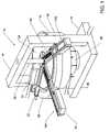
- FIG. 1is a schematic top perspective view of one embodiment of an apparatus for 3D printing in accordance with the invention
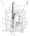
- FIG. 2is an enlarged schematic side perspective view of the apparatus of FIG. 1 ;
- FIG. 3is an enlarged schematic perspective view of a portion of the apparatus of FIG. 1 ;
- FIG. 4is a schematic top view of the apparatus of FIG. 1 illustrating the spreader apparatus
- FIG. 5Ais a schematic partial cross-sectional view of the apparatus of FIG. 1 taken at line 5 A- 5 A in FIG. 4 ;
- FIG. 5Bis an enlarged schematic perspective view of an overflow sensor in accordance with the invention.
- FIG. 6Ais a schematic perspective view of one embodiment of a system for 3D printing including a 3D printing apparatus and a build material delivery system in accordance with the invention
- FIG. 6Bis a schematic perspective view of an alternative embodiment of a system for 3D printing including a 3D printing apparatus and a build material delivery system in accordance with the invention
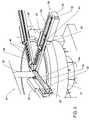
- FIG. 7Ais a schematic perspective view of one embodiment of an apparatus for 3D printing in accordance with the invention with a build drum partially cut-away;
- FIG. 7Bis a schematic perspective view of the apparatus of FIG. 7A with a portion of the build material removed from the build drum;
- FIG. 8Ais an enlarged schematic perspective of one embodiment of a printbar assembly including a print diagnostic station in accordance with the invention.
- FIG. 8Bis a schematic representation of the diagnostic station of FIG. 8A ;
- FIGS. 9A-9Jare schematic representations of one embodiment of an apparatus and method for cleaning a printhead in accordance with the invention.
- FIG. 10is a schematic representation of one step of the method of cleaning a printhead depicted in FIGS. 9A-9J ;
- FIG. 11is a schematic perspective view of an alternative embodiment of a printhead cleaning station in accordance with the invention.
- FIGS. 12A-12Care schematic side and perspective views of a printhead being cleaned at the cleaning station of FIG. 11 ;
- FIGS. 13A-13Dare schematic perspective views of another alternative embodiment of a printhead cleaning station in accordance with the invention.
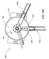
- FIGS. 14A-14Dare schematic representations of one embodiment of a radial printing process in accordance with the invention.
- FIGS. 15A and 15Bare schematic top views of an alternative embodiment of an apparatus for 3D printing in accordance with the invention.
- FIGS. 1-3depict an apparatus 10 for 3D printing.
- the apparatus 10produces three-dimensional objects by depositing alternating layers of build material and binder on a build surface or in a container to print multiple layers that ultimately form the three-dimensional object.
- the apparatus 10includes a rotary build table, in this case a build drum 12 , a structural frame 14 , a base 16 , at least one printbar assembly 18 , a powdered build material dispenser assembly 20 , and a spreader assembly 22 .
- the apparatus 10includes two printbar assemblies 18 A, 18 B.
- the apparatus 10further includes a component-mounting surface 26 attached to the frame 14 .
- the component mounting surface 26may be movable to provide access to the build drum 12 .
- the various assemblies 18 , 20 , 22are typically mounted to the component mounting surface 26 and/or the frame 14 . It is generally advantageous, for maintenance purposes, for the assemblies 18 , 20 , 22 to be stationary and the build drum 12 to rotate. For example, with redundant stationary printbar assemblies 18 , a user can change out one printbar assembly 18 while the other printbar assembly 18 continues to operate.
- the apparatus 10can include essentially any number of printbar assemblies 18 mounted in a variety of configurations for accomplishing printhead redundancy, increasing print speeds, and/or printing multiple colors.
- the build drum 12 shownis generally cylindrical in shape and is mounted about a center shaft 28 attached to the base 16 and the frame 14 .
- a bottom surface 17 of the build drum 12may be substantially perpendicular to a sidewall 19 of the build drum 12 , or the bottom surface 17 can be angled.
- the bottom surface 17may be conical, such that the surface tilts toward a center point of the build drum 12 .
- the tiltmay be from about 1 degree to about 15 degrees or more.
- the dispenser, the spreader, and the printbarsshould be slanted to correspond to the angle of tilt.
- the build drum 12is mounted on a rotary actuator 29 that rotates the build drum 12 about the center shaft 28 .
- the rotary actuator 29could be hydraulically, pneumatically, or electrically driven.
- the rotary actuator 29can include gears and belts for driving the build drum 12 .
- the rotary actuator 29may include one or more encoders 46 , or similar devices, that cooperate with a controller to monitor and adjust the speed and/or position of the build drum 12 .
- the encoders 46can also be used to control the firing of the printheads 48 , such that the printheads 48 print accurately and repeatedly, regardless of variations in the rotational speed of the build drum 12 .
- the build drum 12receives build material from the build material dispenser assembly 20 that is located adjacent to the build drum 12 .
- the build material dispenser assembly 20is mounted above the build drum 12 and dispenses build material onto the build drum 12 as it rotates.
- the build material dispenser assembly 20deposits a predetermined amount of material onto the build drum 12 in the form of a line substantially along a radius of the build drum 12 .
- the build material dispenser assembly 20could include nozzles for spraying the material onto the build drum 12 .
- the build material dispenser assembly 20could include a volumetric adjuster, for manually or automatically adjusting the amount of material being deposited.
- the build material dispenser assembly 20is supported on the component-mounting surface 26 .
- the build material dispenser assembly 20may be supplied by a larger dispenser assembly located remotely from the apparatus 10 (see FIGS. 6A and 6B ). Further, the build material dispenser assembly 20 may include an agitator to maintain the build material in a loose powder form.
- the spreader assembly 22Located adjacent the build material dispenser assembly 20 is the spreader assembly 22 .
- the spreader assembly 22spreads the build material uniformly across the build drum 12 as it rotates.
- the spreader assembly 22is shown in greater detail in FIG. 3 .
- the spreader assembly 22includes a counter-rotating spreader roll 52 that spreads the build material radially across the build drum 12 , thereby forming a build surface 24 .
- the spreader assembly 22also includes a roll scraper 54 that removes build material that may become stuck to the roll 52 .
- the spreader assembly 22is also mounted on the component-mounting surface 26 .
- the build drum 12moves downwardly relative to the assemblies 18 , 20 , 22 mounted on the component mounting surface 26 .
- the build drum 12moves downwardly relative to the assemblies 18 , 20 , 22 mounted on the component mounting surface 26 .
- at least a portion of the center shaft 28 and the build drum 12are threaded and the build drum 12 threadedly engages the center shaft 28 .
- the build drum 12moves down the center shaft 28 .
- the build drum 12includes a bottom surface 17 that moves downwardly relative to the build drum 12 to continuously receive layers of build material.
- the bottom surface 17is moved vertically by one or more linear actuators 191 .
- the linear actuatorscould be hydraulically, pneumatically, or electrically driven.
- the assemblies 18 , 20 , 22move upwardly relative to the build drum 12 and the build surface 24 .
- the build drum 12may include structure for facilitating removal of completed parts.
- the build drum 12includes an opening in its bottom or side surface that allows for removal of the parts from the bottom and/or side, while the apparatus 10 continues to print above.
- the apparatus 10may print a bottom plate covering essentially the entire build surface 24 before printing any parts. The bottom plate(s) would separate the layers of printed parts to prevent the inadvertent removal of build material or unfinished parts.
- the usercould stop the printing process and remove the parts manually from the top, bottom, or side (see FIGS. 7A and 7B ).
- the spreader assembly 22is disposed slightly non-radially, with respect to the build drum 12 .
- the build material dispenser assembly 20deposits a substantially radial line of material in front of the spreader assembly 22 as the build drum 12 rotates (arrow 44 ).
- the apparatus 10can be configured to operate with the drum 12 rotating in a counter-clockwise direction when viewed from the top as illustrated or clockwise in a mirror image of the configuration shown.
- the non-radial spreader assembly 22spreads the material, forcing the excess material to migrate towards a center opening 56 in the build drum 12 .
- the excess materialfalls into an overflow tray 68 (see FIGS. 1-2 ) located beneath the build drum 12 .
- the apparatus 10is configured to reclaim the excess material for later use.
- the apparatus 10includes an overflow sensor 58 .
- the sensor 58monitors the amount of excess material falling through the center opening 56 .
- the sensor 58sends a signal to the apparatus controller indicative of the amount of excess material measured.
- the apparatus 10can, in response to the signal, adjust the amount of material dispensed by the build material dispenser assembly 20 .
- FIGS. 5A and 5BThe sensor 58 is shown in greater detail in FIGS. 5A and 5B .
- FIG. 5Adepicts the general location of the sensor 58 on the apparatus 10 .
- the sensor 58is disposed within the center opening 56 and is mounted to the non-rotating center shaft 28 .
- FIG. 5Bis an enlarged view of the sensor 58 .
- the sensor 58includes a shaft 66 for mounting the sensor 58 to the center shaft 28 .
- At a distal end of the shaft 66is a paddlewheel assembly including a magnetic sensor 60 and a series of magnets 62 located on individual legs 64 of the paddlewheel 65 . As excess material falls, it impinges on the legs 64 , causing the paddle wheel 65 to rotate. The speed and/or period of rotation can be used to ascertain the amount of excess material being deposited, which can be adjusted accordingly. Alternatively, other types of sensors or more than one sensor can be used.
- Each printbar assembly 18includes a printhead carrier 42 , for carrying at least one printhead 48 , a service station 34 , a printhead diagnostics station 38 , a printbar motor 36 , a printbar cable guide 32 , and a printbar slide 30 .
- One of the two assemblies 18 A, 18 Bcan be redundant to the other. Alternatively, many more printbar assemblies 18 could be included on the apparatus 10 .
- the printbar cable guide 32guides and secures the electrical connections to the printheads 48 .
- the printbar slide 30is attached to the component-mounting surface 26 and supports the printhead carrier 42 , the service station 34 , the printhead diagnostics station 38 , and the printbar motor 36 .
- the print bar motor 36can be a servo type motor, used to radially move the printbar assembly 18 relative to the build drum 12 along the slide 30 . It is generally advantageous to use a positioning system capable of accurate and repeatable control, because this directly influences the accuracy of the objects being produced.
- the printhead carrier 42is radially movable to position the printheads 48 for printing and for performing service on the printheads 48 .
- the printhead carrier 42can be moved along a radius of the build drum 12 to correct for deficiencies in print quality.
- the printhead carrier 42supports a printhead array 40 , which may include any number of printheads 48 , for example a single printhead 48 or eight rows of six printheads 48 .
- the printhead array 40may include redundant printheads 48 , which compensate for the deficiencies in print quality.
- the printheads 48can be commercially available inkjet type printheads or custom manufactured printheads to suit a particular application.
- the printheads 48include multiple jets, for example 512 jets, each jet for depositing a drop of binder onto the build surface 24 .
- the printheads 48can be moved incrementally back and forth along the radius in a “shingling” fashion to compensate for irregularities in printing, for example, if some jets are not working, misfire, or are out of alignment.
- Shinglingallows the apparatus 10 to produce stronger parts, because printing errors are averaged out.
- shinglingreduces the affect of jets that are not printing properly by offsetting the jets by a small amount such that any line of unprinted build material caused by a missing jet is in a different location on each print layer.
- Shinglingcan be carried out in various ways, for example, in response to an error message or the apparatus 10 can be programmed to continuously shingle by moving the printheads 48 in and out along the radius a random distance between the printing of each layer.
- the apparatus 10can be programmed to run a printing routine, where the printheads 48 are moved a set distance for a specific number of print layers and then reset to a starting position. For example, the printheads 48 can be moved out along the radius 1/16′′ for each print layer until the printheads 48 have been moved a total of 1 ⁇ 4′′. Then, the printheads 48 can be moved back in along the radius to their starting position or be moved back incrementally. Therefore, the apparatus 10 is printing over the same areas with different printheads 48 to average out any errors.
- FIGS. 14A-14Ddepict generally a radial scanning print process, where a printhead array moves continuously in and out along a radius of a build drum, as the build drum rotates continuously. In such a process, the printhead array scans an entire build surface of the 3D printer.
- FIG. 14Ais a schematic isometric view of a 3D printer 200 in accordance with the invention.
- the 3D printer 200is similar to the 3D printer 10 previously described with respect to FIGS. 1-3 .
- the 3D printer 200includes a build drum 212 and two printbar assemblies 201 A, 201 B. Each printbar assembly 201 A, 201 B includes a printhead array 202 .
- FIG. 14Bis a schematic top view of the 3D printer 200 of FIG. 14A .
- the printbar assemblies 201 A, 201 Binclude printhead carriers 203 that move in and out, generally along a radius of the build drum 212 , as shown by arrow 204 .
- the build drum 212includes a build surface 224 and rotates counter-clockwise, as shown by arrow 244 .
- the build drum 212moves relatively slowly, while the printhead carriers 203 move more rapidly.
- FIGS. 14C and 14Dare enlarged schematic top views of the 3D printer 200 of FIG. 14A .
- the printhead array 202includes six printheads 248 staggered along a length of the printhead carrier 203 ; however, the array 202 could be made up of essentially any number or arrangement of printheads 248 .
- the six staggered printheads 248define the printing swath width 206 .
- each printhead 248prints a 1 ⁇ 2′′ swath, resulting in a swath width 206 of about 3′′.
- the width 206is obtained with all of the jets printing; however, different swath widths and shapes can be achieved by controlling the number and arrangement of jets that actually fire.
- the printhead carrier 203moves the printhead array 202 radially in and out, the printheads 248 print on the in stroke, as shown by arrow 205 .
- FIG. 14Ddepicts the specific details of the print swaths.
- the swathsprint canted to a radius of the build drum 212 , because the build drum 212 is rotating as the printheads 248 are printing along the radius.
- the printhead travel path 207includes a print stroke 208 and a return stroke 209 (the lines shown represent the centerline of the printhead array 202 ).
- the return stroke 209occurs as the printhead carrier 203 moves radially outward, and the print stroke 208 occurs as the printhead carrier 203 moves radially inward.
- not all of the jetsare firing along the entire print stroke 208 , resulting in a used printable area 213 and an unused printable area 211 .
- the used printable area 213 of the swathis widest at a point furthest from the center of the build drum 212 .
- the various 3D printers disclosed hereinprint based on polar coordinates (i.e., r, ⁇ ), as opposed to linear printers, which print based on rectangular coordinates (i.e., x, y).
- the disclosed 3D printersinclude logic for converting rectangular coordinates to polar coordinates for printing on a radial build surface.
- the converting logictypically resides in the controller that controls the operation of the 3D printer.
- the printheadsare printing along a radius, not all of the jets of the printhead print every time.
- the jets located closest to the center of the print arraystend to print less, thereby resulting in a longer duty life.
- the printheads located on the outsides of the print arraystend to fail first.
- the apparatus 10can include one or more sensors to measure the print quality or other characteristics of the apparatus 10 , such as print speed, printhead condition (e.g., an empty or dirty printhead), misfiring jets, build material quantity, and/or build drum position.
- a sensorcan monitor the print quality by determining if the printheads 48 are printing properly and, if not, can send a signal to the apparatus controller to shift the printheads 48 to compensate for printheads 48 that are not printing properly. For example, the controller could move the printheads 48 radially a very small amount for shingling purposes.
- a sensorcan be used to determine whether all, or at least a minimum number, of jets are firing and, if not, signal the user to replace a printhead 48 . Additionally, sensors can be used to monitor and control other functions, such as running diagnostic tests, performing cleaning of the printheads 48 , refilling the build material dispenser assembly 20 , cleaning the spreader assembly 22 , and performing any other desired function of the apparatus 10 .
- the printbar assembly 18can also be moved for diagnostic or service purposes. Moving the printhead array 40 radially from the build drum 12 provides the user with access to the printheads 48 for maintenance purposes, such as cleaning or replacement. Printhead cleaning is described in detail with respect to FIGS. 9A-9J , 10 , 11 , 12 A- 12 C, and 13 A- 13 D.
- the printhead array 40can also be moved radially outwardly to run a diagnostic routine of the printhead array 40 (see FIGS. 8A and 8B ).
- the printbar assembly 18can be raised from the build drum 12 for service purposes.
- the size and exact configuration of the apparatus 10can vary to suit a particular application.
- the apparatus 10could be sized to fit on a tabletop to produce relatively small three-dimensional objects, or the apparatus 10 could have a substantial footprint for producing relatively large three-dimensional objects.
- the build drum 12has an outside diameter of about six feet, an inside diameter of about two feet, and a depth of about two feet.
- the size of the build drum 12can vary to suit a particular application.
- the apparatus 10can be situated within an enclosure and can include air handling equipment for cleaning the work environment. The enclosure can include windows for monitoring operation of the apparatus 10 .
- the apparatus 10may include multiple build drums 12 and printbar assemblies 18 .
- the apparatus 10includes multiple build drums 12 spaced about a centrally located gantry that carries the printing components, i.e., material dispenser, spreader, and the printheads.
- the gantrycan be rotated into position above one of the build drums 12 .
- the usercan be printing on one build drum 12 while removing parts from another build drum 12 , thereby allowing for continuous operation.
- the build drum 12can be radially stationary, but vertically movable.
- the printing componentsare configured to move radially about the build drum 12 .
- the gantry supporting the printing componentsrotates radially about the build drum 12 while the printheads move back and forth along a radius of the build drum 12 . This configuration allows for printing over substantially the entire surface area of the build drum 12 .
- FIGS. 15A and 15Bdepict an alternative embodiment of a 3D printing apparatus 300 in accordance with the invention.
- the apparatus 300includes three build drums 312 disposed on a carousel 313 .
- the printing hardwareis stationary as the carousel 313 rotates the build drums 312 around a carousel pivot shaft 314 into alignment with the printing hardware.
- the build drums 312 and printing hardwareare essentially the same as previously described.
- FIG. 15Bdepicts the carousel 313 rotating counter-clockwise (arrow 315 ) to move one build drum 312 A out of alignment with the printing hardware and a second build drum 312 B into alignment with the printing hardware.
- the carouselcan rotate in either the clockwise or counter-clockwise direction.
- One advantage to this arrangementis that the apparatus 300 can be printing on one build drum 312 C, while one set of printed objects can be curing in the second build drum 312 B and another set of printed objects are being removed from the third build drum 312 A.
- FIGS. 6A and 6Bdepict systems 70 , 92 for 3D printing utilizing two different build material feed systems 74 , 96 .
- the system 70includes a 3D printing apparatus 72 , similar to that previously described with respect to FIGS. 1-3 , and the build material feed system 74 remotely connected to the 3D printing apparatus 72 .
- the build material feed system 74includes a storage bin, or hopper 80 , for holding the build material and structure for conveying the build material to the 3D printing apparatus 72 .
- the hopper 80may include multiple internal compartments for holding multiple build material components that are mixed before being conveyed to the three-dimensional printing apparatus 72 . Additionally, the multiple compartments might hold different types of build materials, with the build material feed system 74 including structure for delivering one or more different materials to the apparatus 72 .
- the build material feed system 74 shown in FIG. 6Aincludes a supply duct 82 , a supply pump 84 , a return (or overflow) duct 88 , and a return (or overflow) pump 90 .
- These components 82 , 84 , 88 , 90connect the hopper 80 with the 3D printing apparatus 72 and are capable of conveying a continuous or intermittent flow of material to the 3D printing apparatus 72 , as needed.
- the ducts 82 , 88can be rigid or flexible or combinations thereof.
- a flexible hosecan be used at the connection points between the ducts 82 , 88 and the 3D printing apparatus 72 , while the portion of the ducts 82 , 88 running between the build material feed system 74 and the 3D printing apparatus 72 can be rigid pipe.
- the build material feed system 74could include a conveyer belt system, a carousel, a feed screw, a gravity feed system, or other known components for transporting loose powder materials. The systems could be operated manually or driven pneumatically, hydraulically, or electrically.
- the build material feed system 74may include a main fill port or duct 86 on the hopper 80 . Further, the build material feed system 74 may include one or more sensors connected to the controller 73 to monitor and control material levels in the hopper 80 and/or the amount and the rate of the materials being delivered to the 3D printing apparatus 72 .
- the hopper 80is filled with build material, typically in powder form, via the duct 86 .
- the hopper 80may include a removable cover for filling.
- the materialis directly fed to the 3D printing apparatus 72 via the supply duct 82 exiting the bottom of the hopper 80 .
- the supply pump 84is located in the supply duct 82 to facilitate transportation of the material to a build material dispenser assembly 76 on the 3D printing apparatus 72 .
- the excess materialis collected in a material overflow tray 78 located on the 3D printing apparatus 72 and returned directly to the hopper 80 via the return duct 88 and the return pump 90 located in the return duct 88 .
- the materialis returned to the top of the hopper 80 .
- the return materialis processed before being returned to the hopper 80 .
- the build material feed system 74may include an agitation component to maintain the build material in a powder form.
- the build material feed system 74may include components for handling build materials supplied in other than powder form.
- the system 92includes a 3D printing apparatus 94 , similar to that previously described with respect to FIGS. 1-3 , and the build material feed system 96 remotely connected to the 3D printing apparatus 94 .
- the build material feed system 96is similar to the system 74 described with respect to FIG. 6A and includes a hopper 102 , a supply duct 106 , a supply pump 108 , a return (or overflow) duct 114 , and a return (or overflow) pump 116 .
- the build material feed system 96further includes a blending assembly 110 .
- the blending assembly 110is disposed in the supply duct feeding the 3D printing apparatus 94 ; however, the blending assembly 110 could be located in the hopper 102 to blend the materials before they leave the hopper 102 .
- the blending assembly 110includes multiple component hoppers 112 .
- the main hopper 102holds one or more of the major constituents of the build material that are supplied to the blending assembly 110 , such as sand.
- One or more additional constituentsare introduced to the blending assembly 110 via the component hoppers 112 .
- the blending assembly 110controls the feed rate and blending of the various constituents to create the final build material.
- the blending assembly 110can blend the excess material received from the return duct 114 into the build material supplied to the 3D printing apparatus 94 .
- the blending assembly 110meters the excess material into the blended build material in such a manner as to not effect the quality of the material being delivered to the 3D printing apparatus 94 .
- FIGS. 7A and 7Bdepict the removal of three-dimensional objects or printed parts 126 from one embodiment of a 3D printing apparatus 120 in accordance with the invention.
- the build drum 124is shown in partial section to illustrate the positioning of the printed parts 126 .
- Layers of the build materialaccumulate in the build drum 124 and the printed parts 126 are surrounded by non-printed (unbound) build material 128 .
- the unbound build material 128is evacuated from the build drum 124 by, for example, vacuuming.
- the unbound material 128could be drained through bottom or side openings in the build drum 124 .
- the parts 126can be manually or automatically removed from the build drum 124 .
- the top opening 122is partially covered. The parts 126 may be further processed, as needed.
- FIGS. 8A and 8Billustrate the diagnostic station 38 of FIG. 1 .
- Other diagnostic systemsare possible; for example detecting drops of binder or printing a test pattern on the build material.
- the diagnostic station 38as shown in detail in FIG. 8B , includes chart paper 130 mounted between a paper supply roll 132 and a paper take-up roll 134 , an optical scanner 138 , a fixed reference printhead 140 , and a paper drive capstan 136 .
- the capstan 136is used to accurately feed and position the chart paper 130 .
- a portion of the printhead array 40is moved in position over the diagnostic station 38 (arrow 142 in FIG. 8A ).
- a clean section of chart paper 130is positioned below the printhead array 40 (arrow 144 in FIG.
- the printheads 48including the reference printhead 140 , print on the chart paper 130 .
- the printed test patternis passed under the optical scanner 138 for analysis.
- the optical scanner 138is a CCD camera that reads the test image.
- the apparatus controller 73via the diagnostic station 38 , is able to determine if the printheads 48 are printing correctly or are in need of cleaning or replacement.
- the chart paper 130may move continuously while the printhead array 40 moves continuously over it, printing a test pattern on the paper.
- FIGS. 9A-9Jillustrate a system 146 for cleaning a printhead 150 .
- the system 146is located in the service station 34 ( FIG. 1 ).
- the system 146includes a cleaning station 148 made up generally of a latch pawl 152 , a spring 154 , a squeegee 156 , a printhead cap 158 , a cap carrier 192 , a second spring 162 , and a cam track 164 .
- Only a single cleaning station 148is shown for descriptive purposes; however, multiple stations 148 may be disposed in the service station 34 .
- a single cleaning station 148may service multiple printheads 150 by, for example, successively positioning the printheads 150 relative to the cleaning station 148 .
- FIG. 9Arepresents a starting position of the cleaning system 146 .
- the printhead 150approaches the cleaning station 148 and engages the latch pawl 152 .
- the latch pawl 152is actuated as the printhead 150 passes over the latch pawl 152 .
- the printhead 150continues to move past the latch pawl 152 and engages the squeegee 156 ( FIG. 9C ).
- the printhead 150passes over squeegee 156 .
- the printhead 150contacts the cap carrier 192 , which is driven along the cam track 164 and compresses the spring 162 .
- the printhead cap 158is positioned against a printhead face 160 ( FIGS. 9E and 9F ).
- the printhead cap 158seals against the printhead face 160 while the face 160 is rinsed with wash fluid (see FIG. 10 ).
- the printhead 150After the printhead face 160 is cleaned, the printhead 150 begins to move out of the cleaning station 148 ( FIG. 9G ).
- the latch pawl 152engages the cap carrier 192 , halting its movement.
- the printhead 150engages the squeegee 156 , which wipes the printhead face 160 .
- the squeegee 156vibrates to further clean the printhead face 160 .
- the printhead 150continues its forward movement, actuating the latch pawl 152 ( FIG. 91 ), which, in turn, releases the cap carrier 192 ( FIG. 9J ).
- the cap carrier 192snaps back to the start position.
- the system 146is now ready to clean another printhead 150 .
- FIG. 10depicts the action of FIG. 9F in greater detail.
- the printhead 150is positioned with the printhead face 160 against the printhead cap 158 , which in this embodiment is made of rubber.
- the capincludes a seal lip 172 for sealing about the printhead face 160 .
- the cleaning station 148is coupled to a wash fluid supply container 182 via a supply duct 184 and a wash fluid return container 186 via a return duct 188 .
- the wash fluid return container 186is in communication with a vacuum source 180 , in this case a vacuum pump, via a vacuum duct 190 .
- a valve 178is located in the return duct 188 . The valve 178 may be manually or automatically actuated.
- the vacuum source 180creates a vacuum within a cavity 174 in the printhead cap 160 .
- the vacuumpulls wash fluid from the supply container 182 through the supply duct 184 .
- the wash fluidenters the cavity 174 as a spray 176 against the printhead face 160 .
- the spray 176washes debris, such as excess build material and dried binder, off the printhead face 160 .
- the used wash fluid and debrisare drawn out of the cavity 174 by the vacuum source 180 and into the return container 186 via the return duct 188 .
- the negative pressure created in the cavity 174 by the vacuum source 180prevents the wash fluid from entering the jet nozzles and, in fact, may cause a small amount of binder to flow out of the nozzles to flush any powdered build material out of the nozzle. Blockages or obstructions in the jet nozzles can cause the jets to fire in the wrong direction.
- FIG. 11depicts an alternative embodiment of a cleaning station, also referred to as a reconditioning station 406 .
- the reconditioning station 406is shown removed from the printing apparatus 10 ; however, the reconditioning station 406 can be included on the printbar assembly 18 or in the service station 34 .
- the reconditioning station 406includes a plurality of wiping elements 408 and a plurality of lubricators 410 .
- the wiping elements 408 and the lubricators 410are mounted on a plate 412 that can be actuated to travel, as indicated by arrow 401 .
- the engaging surfaces 414 of the wiping elements 408 and the lubricators 410are disposed upwards so that when the printhead 476 is in the reconditioning station 406 , the wiping elements 408 and the lubricators 410 clean the printheads 476 from below ( FIGS. 12A-12C ). Also, in the illustrated embodiment, one wiper 408 and one lubricator 410 acting as a pair 416 are used to clean each printhead 476 . Further, in the illustrated embodiment, each wiper and lubricator pair 416 are offset from each other to correspond with the offset spacing of the printheads 476 (see, for example, printheads 48 in FIG. 8A ). In other embodiments, however, any number of wiping elements 408 and lubricators 410 can be used to clean the printheads 476 , and the wiping elements 408 and lubricators 410 can be spaced using any desirable geometry.
- FIGS. 12A-12Cdepict one method of using the reconditioning station 106 .
- the printhead(s) 476is disposed above the reconditioning station 406 ( FIG. 12A ).
- the plate 412 on which the wiping elements 408 and lubricators 410 are mountedis then actuated into alignment with the printheads 476 , and the printheads 476 are wiped and lubricated from beneath to remove any accumulated grit and to improve the flow of binding material out of the printheads 476 .
- the lubricator 410applies a lubricant to the printhead face 477 to moisten any debris on the printhead face 477 .
- the printhead 476is moved to pass the printhead face 477 over the wiping element 408 (e.g., a squeegee), which wipes the printhead face 477 clean.
- the printhead face 477could be exposed to a vacuum source to remove any debris present thereon.
- FIGS. 13A-13Ddepict an alternative embodiment of a reconditioning station 506 in accordance with the invention.
- the reconditioning station 506may also be mounted in the service station 34 .
- the reconditioning station 506includes a reservoir 542 that holds a washing solution 543 and a pump 545 that delivers the washing solution 543 under pressure to at least one nozzle 540 and preferably an array of nozzles 540 .
- the nozzles 540are capable of producing a high velocity stream of washing solution 543 . In operation, the nozzles 540 are directed to the printhead face 577 of the printhead 576 .
- the washing solution 543loosens and removes contaminants, such as build material and binding material, from the printhead face 577 .
- the orientation of the nozzles 540may be angled with respect to the printhead face 577 , such that a fluid flow is induced across a plane of the printhead face 577 .
- the washing solutioncan contact the printhead 576 at the side nearest the nozzles 540 and drain from the side of the printhead 576 furthest from the nozzles 540 .
- a splash guardmay also be included in the reconditioning station 506 to contain splashing resulting from the streams of liquid washing solution 543 .
- a wicking member 544may be disposed such that the printhead face 577 may pass one or more times over its upper surface 546 in close proximity, without contact, allowing capillary forces to draw accumulated washing solution 543 away from the printhead face 577 .
- the wicking member 544may be made from rigid, semi-rigid, or compliant materials, and can be of an absorbent or impermeable nature, or any combination thereof.
- the gap between the upper surface 546 of the wicking member 544 and the printhead face 577must be small, a desirable range being between about 0 inches to about 0.03 inches.
- a further object of this inventionis to provide a means for maintaining the gap in this range without resort to precise, rigid, and costly components.
- the wicking member 544may consist of a compliant rubber sheet oriented approximately orthogonal to the direction of relative motion 547 between the wicking member 544 and the printhead 576 and with a portion of its upper edge 546 disposed so that it lightly contacts or interferes with the printhead face 577 only in non-critical areas away from the printhead nozzle orifices.
- the upper edge 546 of the wicking member 544may include one or more notches 548 at locations where the wicking member 544 might otherwise contact delicate components of the printhead face 577 .
- wicking member 544always contacts the printhead face 577 , and is deflected as the printhead 576 passes over it, independent of expected variations in the relative positions of the printhead 576 and the reconditioning station 506 .
- the upper edge 546accordingly follows the position of the printhead face 577 , maintaining by extension a substantially constant space between the printhead face 577 and the relieved surface notch 548 .
- a bending zone of the wicking object 544can be of reduced cross-section to provide reliable bending behavior with little deformation of the upper edge 546 of the wicking member 544 .
- FIGS. 13B-13Dillustrate a reconditioning cycle in accordance with the invention.
- FIG. 13Bshows the printhead 576 approaching the reconditioning station 506 along the path 547 .
- the printhead 576lightly contacts the wiping member 544 , as shown in FIG. 13C , motion stops along the path 547 and the washing solution 534 is directed at the printhead face 577 by the nozzle array 540 .
- the spraying operationis complete, the printhead 576 continues to travel along the path 547 , as shown in FIG. 13D .
- the wiping member 544is further deflected to allow passage of the printhead 576 , and the accumulated washing solution 543 is wicked away from the printhead face 577 .
- the printhead 576may print a plurality of droplets to eject any washing solution that may have been ingested during the reconditioning process.
- a cleaning systemcould include a continuous filament that carries wash fluid up to a printhead face and carries debris away to a sump.
- the systemmay include a small scraper that can be run over the filament to remove built up debris.
Landscapes
- Engineering & Computer Science (AREA)
- Chemical & Material Sciences (AREA)
- Materials Engineering (AREA)
- Manufacturing & Machinery (AREA)
- Physics & Mathematics (AREA)
- Mechanical Engineering (AREA)
- Optics & Photonics (AREA)
Abstract
Description
Claims (26)
Priority Applications (2)
| Application Number | Priority Date | Filing Date | Title |
|---|---|---|---|
| US10/817,159US7291002B2 (en) | 2003-05-23 | 2004-04-02 | Apparatus and methods for 3D printing |
| US11/860,087US20080042321A1 (en) | 2003-05-23 | 2007-09-24 | Apparatus and Methods for 3D Printing |
Applications Claiming Priority (2)
| Application Number | Priority Date | Filing Date | Title |
|---|---|---|---|
| US47292203P | 2003-05-23 | 2003-05-23 | |
| US10/817,159US7291002B2 (en) | 2003-05-23 | 2004-04-02 | Apparatus and methods for 3D printing |
Related Child Applications (1)
| Application Number | Title | Priority Date | Filing Date |
|---|---|---|---|
| US11/860,087ContinuationUS20080042321A1 (en) | 2003-05-23 | 2007-09-24 | Apparatus and Methods for 3D Printing |
Publications (2)
| Publication Number | Publication Date |
|---|---|
| US20040265413A1 US20040265413A1 (en) | 2004-12-30 |
| US7291002B2true US7291002B2 (en) | 2007-11-06 |
Family
ID=33490538
Family Applications (2)
| Application Number | Title | Priority Date | Filing Date |
|---|---|---|---|
| US10/817,159Expired - LifetimeUS7291002B2 (en) | 2003-05-23 | 2004-04-02 | Apparatus and methods for 3D printing |
| US11/860,087AbandonedUS20080042321A1 (en) | 2003-05-23 | 2007-09-24 | Apparatus and Methods for 3D Printing |
Family Applications After (1)
| Application Number | Title | Priority Date | Filing Date |
|---|---|---|---|
| US11/860,087AbandonedUS20080042321A1 (en) | 2003-05-23 | 2007-09-24 | Apparatus and Methods for 3D Printing |
Country Status (4)
| Country | Link |
|---|---|
| US (2) | US7291002B2 (en) |
| EP (1) | EP1628831A2 (en) |
| JP (1) | JP2007503342A (en) |
| WO (1) | WO2004106041A2 (en) |
Cited By (153)
| Publication number | Priority date | Publication date | Assignee | Title |
|---|---|---|---|---|
| US20080047628A1 (en)* | 2006-05-26 | 2008-02-28 | Z Corporation | Apparatus and methods for handling materials in a 3-D printer |
| US20090126225A1 (en)* | 2007-10-23 | 2009-05-21 | Nike, Inc. | Articles And Methods Of Manufacturing Articles |
| US20100095557A1 (en)* | 2007-10-23 | 2010-04-22 | Nike, Inc. | Articles And Methods Of Manufacture Of Articles |
| DE102010015451A1 (en) | 2010-04-17 | 2011-10-20 | Voxeljet Technology Gmbh | Method and device for producing three-dimensional objects |
| US20120072001A1 (en)* | 2010-09-17 | 2012-03-22 | Synerdyne Corporation | Remote monitoring and control of a three-dimensional object in a fabrication apparatus |
| US8567477B2 (en) | 2012-02-29 | 2013-10-29 | Ford Global Technologies, Llc | Mold core for forming a molding tool |
| US20130287933A1 (en)* | 2012-04-25 | 2013-10-31 | Pierre J. Kaiser | Three-dimensional (3d) printing |
| US8627876B2 (en) | 2012-02-29 | 2014-01-14 | Ford Global Technologies, Llc | Molding tool with conformal portions and method of making the same |
| WO2014039378A1 (en) | 2012-09-05 | 2014-03-13 | Aprecia Pharmaceuticals Company | Three-dimensional printing system and equipment assembly |
| WO2014055614A1 (en) | 2012-10-04 | 2014-04-10 | Townsend Industries, Inc. D/B/A/ Townsend Design | Method of preparing an image for use in production of a knee brace and a tibial contour gauge and an image alignment guide for use in said method |
| WO2014014977A3 (en)* | 2012-07-18 | 2014-05-08 | Tow Adam P | Systems and methods for manufacturing of multi-property anatomically customized devices |
| US8888480B2 (en) | 2012-09-05 | 2014-11-18 | Aprecia Pharmaceuticals Company | Three-dimensional printing system and equipment assembly |
| US9034237B2 (en) | 2012-09-25 | 2015-05-19 | 3D Systems, Inc. | Solid imaging systems, components thereof, and methods of solid imaging |
| US9156204B2 (en) | 2010-05-17 | 2015-10-13 | Synerdyne Corporation | Hybrid scanner fabricator |
| US9314969B1 (en) | 2014-10-20 | 2016-04-19 | Lenovo Enterprise Solutions (Singapore) Pte. Ltd. | Three-dimensional printer having an expandable envelope |
| US9341867B1 (en) | 2015-01-16 | 2016-05-17 | James Chang Ho Kim | Methods of designing and fabricating custom-fit eyeglasses using a 3D printer |
| US9364995B2 (en)* | 2013-03-15 | 2016-06-14 | Matterrise, Inc. | Three-dimensional printing and scanning system and method |
| US9399321B2 (en) | 2009-07-15 | 2016-07-26 | Arcam Ab | Method and apparatus for producing three-dimensional objects |
| US9406483B1 (en) | 2015-01-21 | 2016-08-02 | Arcam Ab | Method and device for characterizing an electron beam using an X-ray detector with a patterned aperture resolver and patterned aperture modulator |
| US9415443B2 (en) | 2013-05-23 | 2016-08-16 | Arcam Ab | Method and apparatus for additive manufacturing |
| US9468973B2 (en) | 2013-06-28 | 2016-10-18 | Arcam Ab | Method and apparatus for additive manufacturing |
| US9505172B2 (en) | 2012-12-17 | 2016-11-29 | Arcam Ab | Method and apparatus for additive manufacturing |
| US9505057B2 (en) | 2013-09-06 | 2016-11-29 | Arcam Ab | Powder distribution in additive manufacturing of three-dimensional articles |
| US9550207B2 (en) | 2013-04-18 | 2017-01-24 | Arcam Ab | Method and apparatus for additive manufacturing |
| US9561542B2 (en) | 2012-11-06 | 2017-02-07 | Arcam Ab | Powder pre-processing for additive manufacturing |
| WO2017034951A1 (en) | 2015-08-21 | 2017-03-02 | Aprecia Pharmaceuticals Company | Three-dimensional printing system and equipment assembly |
| US9650537B2 (en) | 2014-04-14 | 2017-05-16 | Ut-Battelle, Llc | Reactive polymer fused deposition manufacturing |
| US9649812B2 (en) | 2011-01-05 | 2017-05-16 | Voxeljet Ag | Device and method for constructing a laminar body comprising at least one position-adjustable body defining the working area |
| US9664504B2 (en) | 2014-08-20 | 2017-05-30 | Arcam Ab | Energy beam size verification |
| TWI585558B (en)* | 2016-02-05 | 2017-06-01 | 映美科技有限公司 | Three dimensional printing method |
| US9676032B2 (en) | 2013-09-20 | 2017-06-13 | Arcam Ab | Method for additive manufacturing |
| US9676031B2 (en) | 2013-04-23 | 2017-06-13 | Arcam Ab | Method and apparatus for forming a three-dimensional article |
| US20170182709A1 (en)* | 2015-12-29 | 2017-06-29 | Western Digital Technologies, Inc. | Dual head extruder for three-dimensional additive printer |
| US20170182701A1 (en)* | 2015-12-29 | 2017-06-29 | Western Digital Technologies, Inc. | Extruder for three-dimensional additive printer |
| US9718129B2 (en) | 2012-12-17 | 2017-08-01 | Arcam Ab | Additive manufacturing method and apparatus |
| US9782933B2 (en) | 2008-01-03 | 2017-10-10 | Arcam Ab | Method and apparatus for producing three-dimensional objects |
| US9789563B2 (en) | 2013-12-20 | 2017-10-17 | Arcam Ab | Method for additive manufacturing |
| US9788594B2 (en) | 2007-10-23 | 2017-10-17 | Nike, Inc. | Articles and methods of manufacture of articles |
| US9789541B2 (en) | 2014-03-07 | 2017-10-17 | Arcam Ab | Method for additive manufacturing of three-dimensional articles |
| US9802253B2 (en) | 2013-12-16 | 2017-10-31 | Arcam Ab | Additive manufacturing of three-dimensional articles |
| WO2017223309A1 (en) | 2016-06-22 | 2017-12-28 | Mastix, Llc | Oral compositions delivering therapeutically effective amounts of cannabinoids |
| US9878494B2 (en) | 2011-08-31 | 2018-01-30 | Voxeljet Ag | Device for constructing models in layers |
| CN107672156A (en)* | 2017-09-08 | 2018-02-09 | 浙江大学 | A kind of stagewise annular of 3 D-printing scans device |
| US9925721B2 (en) | 2010-02-04 | 2018-03-27 | Voxeljet Ag | Device for producing three-dimensional models |
| US9943981B2 (en) | 2013-12-11 | 2018-04-17 | Voxeljet Ag | 3D infiltration method |
| US9950367B2 (en) | 2014-04-02 | 2018-04-24 | Arcam Ab | Apparatus, method, and computer program product for fusing a workpiece |
| US9964944B2 (en) | 2014-05-15 | 2018-05-08 | Hurco Companies, Inc. | Material processing unit controlled by rotation |
| US9962885B2 (en) | 2010-04-14 | 2018-05-08 | Voxeljet Ag | Device for producing three-dimensional models |
| US10010134B2 (en) | 2015-05-08 | 2018-07-03 | Under Armour, Inc. | Footwear with lattice midsole and compression insert |
| US10010133B2 (en) | 2015-05-08 | 2018-07-03 | Under Armour, Inc. | Midsole lattice with hollow tubes for footwear |
| US10029453B2 (en) | 2016-04-25 | 2018-07-24 | Baldwin Americas Corporation | Modular digital inking system |
| US10039343B2 (en) | 2015-05-08 | 2018-08-07 | Under Armour, Inc. | Footwear including sole assembly |
| US10052682B2 (en) | 2012-10-12 | 2018-08-21 | Voxeljet Ag | 3D multi-stage method |
| US10059062B2 (en) | 2012-05-25 | 2018-08-28 | Voxeljet Ag | Device for producing three-dimensional models with special building platforms and drive systems |
| US10059058B2 (en) | 2012-06-22 | 2018-08-28 | Voxeljet Ag | Device for building a multilayer structure with storage container or filling container movable along the dispensing container |
| US10124531B2 (en) | 2013-12-30 | 2018-11-13 | Ut-Battelle, Llc | Rapid non-contact energy transfer for additive manufacturing driven high intensity electromagnetic fields |
| US10130993B2 (en) | 2013-12-18 | 2018-11-20 | Arcam Ab | Additive manufacturing of three-dimensional articles |
| US10144063B2 (en) | 2011-12-28 | 2018-12-04 | Arcam Ab | Method and apparatus for detecting defects in freeform fabrication |
| US10150247B2 (en)* | 2013-03-12 | 2018-12-11 | Orange Maker LLC | 3D printing using spiral buildup and high viscosity build materials |
| EP3431141A1 (en) | 2013-03-15 | 2019-01-23 | Aprecia Pharmaceuticals LLC | Three-dimensional printing method |
| US10189086B2 (en) | 2011-12-28 | 2019-01-29 | Arcam Ab | Method and apparatus for manufacturing porous three-dimensional articles |
| US10213831B2 (en) | 2012-11-25 | 2019-02-26 | Voxeljet Ag | Construction of a 3D printing device for producing components |
| US10220568B2 (en) | 2013-12-02 | 2019-03-05 | Voxeljet Ag | Interchangeable container with moveable side walls |
| US10226919B2 (en) | 2007-07-18 | 2019-03-12 | Voxeljet Ag | Articles and structures prepared by three-dimensional printing method |
| US10226098B2 (en) | 2013-03-14 | 2019-03-12 | Under Armour, Inc. | Method of making a zonal compression shoe |
| US10245783B2 (en) | 2015-05-21 | 2019-04-02 | Kenneth Fuller | Printer for three dimensional printing |
| US10315250B2 (en) | 2014-06-19 | 2019-06-11 | Halliburton Energy Services, Inc. | Forming facsimile formation core samples using three-dimensional printing |
| US10343301B2 (en) | 2013-02-28 | 2019-07-09 | Voxeljet Ag | Process for producing a moulding using a water-soluble casting mould and material system for the production thereof |
| US10343387B2 (en) | 2016-01-06 | 2019-07-09 | International Business Machines Corporation | Multi-drone based three-dimensional printing |
| EP3524406A1 (en) | 2014-07-13 | 2019-08-14 | Stratasys Ltd. | Method and system for rotational 3d printing |
| US10384435B2 (en) | 2016-01-04 | 2019-08-20 | Caterpillar Inc. | 3D printing |
| US10434572B2 (en) | 2013-12-19 | 2019-10-08 | Arcam Ab | Method for additive manufacturing |
| US10442170B2 (en) | 2013-12-20 | 2019-10-15 | Voxeljet Ag | Device, special paper, and method for producing shaped articles |
| WO2019203847A1 (en)* | 2018-04-20 | 2019-10-24 | Hewlett-Packard Development Company, L.P. | Three-dimensional part printability and cost analysis |
| US10525531B2 (en) | 2015-11-17 | 2020-01-07 | Arcam Ab | Additive manufacturing of three-dimensional articles |
| US10525547B2 (en) | 2016-06-01 | 2020-01-07 | Arcam Ab | Additive manufacturing of three-dimensional articles |
| US10529070B2 (en) | 2017-11-10 | 2020-01-07 | Arcam Ab | Method and apparatus for detecting electron beam source filament wear |
| US10549348B2 (en) | 2016-05-24 | 2020-02-04 | Arcam Ab | Method for additive manufacturing |
| US10582619B2 (en) | 2015-08-24 | 2020-03-03 | Board Of Regents, The University Of Texas System | Apparatus for wire handling and embedding on and within 3D printed parts |
| US10583483B2 (en) | 2015-10-15 | 2020-03-10 | Arcam Ab | Method and apparatus for producing a three-dimensional article |
| US10589460B2 (en) | 2012-03-06 | 2020-03-17 | Voxeljet Ag | Method and device for producing three-dimensional models |
| US10610930B2 (en) | 2015-11-18 | 2020-04-07 | Arcam Ab | Additive manufacturing of three-dimensional articles |
| US10675813B2 (en)* | 2014-11-26 | 2020-06-09 | Homag Bohrsysteme Gmbh | Device for forming 3D bodies |
| US10682809B2 (en) | 2014-12-22 | 2020-06-16 | Voxeljet Ag | Method and device for producing 3D moulded parts by means of a layer construction technique |
| US10691095B2 (en) | 2016-05-02 | 2020-06-23 | Board Of Regents, The University Of Texas System | In-situ diagnostics and control method and system for material extrusion 3D printing |
| US10779614B2 (en) | 2017-06-21 | 2020-09-22 | Under Armour, Inc. | Cushioning for a sole structure of performance footwear |
| US10786865B2 (en) | 2014-12-15 | 2020-09-29 | Arcam Ab | Method for additive manufacturing |
| US10786945B2 (en) | 2013-10-30 | 2020-09-29 | Voxeljet Ag | Method and device for producing three-dimensional models using a binding agent system |
| US10792757B2 (en) | 2016-10-25 | 2020-10-06 | Arcam Ab | Method and apparatus for additive manufacturing |
| US10800101B2 (en) | 2018-02-27 | 2020-10-13 | Arcam Ab | Compact build tank for an additive manufacturing apparatus |
| US10799989B2 (en) | 2007-10-23 | 2020-10-13 | Voxeljet Ag | Pre-assembled module for a device for the layer-wise production of patterns |
| US10807187B2 (en) | 2015-09-24 | 2020-10-20 | Arcam Ab | X-ray calibration standard object |
| US10821514B2 (en) | 2017-05-31 | 2020-11-03 | General Electric Company | Apparatus and method for continuous additive manufacturing |
| US10821721B2 (en) | 2017-11-27 | 2020-11-03 | Arcam Ab | Method for analysing a build layer |
| US10829727B2 (en) | 2018-04-11 | 2020-11-10 | Trustees Of Boston University | Engineered platform to generate 3D cardiac tissues |
| US10843404B2 (en) | 2015-05-20 | 2020-11-24 | Voxeljet Ag | Phenolic resin method |
| US10882110B2 (en) | 2015-09-09 | 2021-01-05 | Voxeljet Ag | Method and device for applying fluids |
| US10913207B2 (en) | 2014-05-26 | 2021-02-09 | Voxeljet Ag | 3D reverse printing method and device |
| US10926466B2 (en) | 2014-10-02 | 2021-02-23 | Hewlett-Packard Development Company, L.P. | Integrated build and material supply for an additive manufacturing apparatus |
| US10946556B2 (en) | 2014-08-02 | 2021-03-16 | Voxeljet Ag | Method and casting mold, in particular for use in cold casting methods |
| US10987868B2 (en)* | 2012-10-31 | 2021-04-27 | Nederlandse Organisatie Voor Toegepast-Natuurwetenschappelijk Onderzoek Tno | Production line for making tangible products by layerwise manufacturing |
| US10987752B2 (en) | 2016-12-21 | 2021-04-27 | Arcam Ab | Additive manufacturing of three-dimensional articles |
| US11014288B2 (en)* | 2012-10-31 | 2021-05-25 | René Jos Houben | Production line for making tangible products by layerwise manufacturing |
| US11014161B2 (en) | 2015-04-21 | 2021-05-25 | Arcam Ab | Method for additive manufacturing |
| US11059123B2 (en) | 2017-04-28 | 2021-07-13 | Arcam Ab | Additive manufacturing of three-dimensional articles |
| US11072117B2 (en) | 2017-11-27 | 2021-07-27 | Arcam Ab | Platform device |
| US11077611B2 (en) | 2015-03-17 | 2021-08-03 | Voxeljet Ag | Method and device for producing 3D shaped articles with a double recoater |
| US11086296B2 (en) | 2018-01-04 | 2021-08-10 | Hurco Companies, Inc. | Additive manufacturing tool |
| US11084205B2 (en) | 2015-07-13 | 2021-08-10 | Stratasys Ltd. | Operation of printing nozzles in additive manufacture and apparatus for cleaning printing nozzles |
| US11097471B2 (en) | 2014-03-31 | 2021-08-24 | Voxeljet Ag | Method and device for 3D printing using temperature-controlled processing |
| US11097469B2 (en) | 2012-10-15 | 2021-08-24 | Voxeljet Ag | Method and device for producing three-dimensional models with a temperature-controllable print head |
| US11148367B2 (en) | 2016-08-31 | 2021-10-19 | Hewlett-Packard Development Company, L.P. | Three-dimensional printing |
| US11148362B2 (en)* | 2016-12-13 | 2021-10-19 | Stratasys, Inc. | Rotary silo additive manufacturing system |
| US11185926B2 (en) | 2017-09-29 | 2021-11-30 | Arcam Ab | Method and apparatus for additive manufacturing |
| US11235518B2 (en) | 2015-12-01 | 2022-02-01 | Voxeljet Ag | Method and device for producing three-dimensional components with the aid of an overfeed sensor |
| US11247274B2 (en) | 2016-03-11 | 2022-02-15 | Arcam Ab | Method and apparatus for forming a three-dimensional article |
| US11247393B2 (en) | 2019-05-30 | 2022-02-15 | General Electric Company | Additive manufacturing systems and methods including rotating binder jet print head |
| US11267051B2 (en) | 2018-02-27 | 2022-03-08 | Arcam Ab | Build tank for an additive manufacturing apparatus |
| US11273605B2 (en) | 2016-11-15 | 2022-03-15 | Voxeljet Ag | Integrated print head maintenance station for powder bed-based 3D printing |
| US11279087B2 (en) | 2017-07-21 | 2022-03-22 | Voxeljet Ag | Process and apparatus for producing 3D moldings comprising a spectrum converter |
| US11292062B2 (en) | 2017-05-30 | 2022-04-05 | Arcam Ab | Method and device for producing three-dimensional objects |
| US11325191B2 (en) | 2016-05-24 | 2022-05-10 | Arcam Ab | Method for additive manufacturing |
| US11325308B2 (en) | 2017-09-01 | 2022-05-10 | Hewlett-Packard Development Company, L.P. | Moving powder in a 3D printing system |
| US20220194004A1 (en)* | 2019-04-17 | 2022-06-23 | DP Polar GmbH | Method for Producing at Least One Solid-Body Layer in Accordance With Predetermined Geometry Data |
| US11383449B2 (en) | 2018-03-29 | 2022-07-12 | Hewlett-Packard Development Company, L.P. | Determining excess build material |
| US11400519B2 (en) | 2018-03-29 | 2022-08-02 | Arcam Ab | Method and device for distributing powder material |
| US11517975B2 (en) | 2017-12-22 | 2022-12-06 | Arcam Ab | Enhanced electron beam generation |
| US11584057B2 (en)* | 2018-01-03 | 2023-02-21 | General Electric Company | Systems and methods for additive manufacturing |
| US11618216B2 (en) | 2020-08-31 | 2023-04-04 | General Electric Company | Additive manufacturing systems and methods including rotating binder jet print head |
| US11820076B2 (en) | 2019-11-01 | 2023-11-21 | Voxeljet Ag | 3D printing process and molding produced by this process using lignosulfate |
| US11826958B2 (en) | 2019-02-05 | 2023-11-28 | Voxeljet Ag | Exchangeable process unit |
| US11890810B2 (en) | 2015-09-16 | 2024-02-06 | Voxeljet Ag | Device and method for producing three-dimensional shaped parts |
| US11964434B2 (en) | 2018-08-16 | 2024-04-23 | Voxeljet Ag | Closure device, 3D printing device and method for producing 3D-molded parts |
| US11975487B2 (en) | 2016-03-09 | 2024-05-07 | Voxeljet Ag | Method and device for producing 3D shaped parts using construction field tools |
| US20240229517A1 (en)* | 2023-01-09 | 2024-07-11 | Volvo Truck Corporation | Security system for vehicle connector port and vehicular apparatus having the security system and the vehicle connector port |
| US12042988B2 (en) | 2019-05-23 | 2024-07-23 | General Electric Company | Additive manufacturing apparatuses and methods |
| US12059841B2 (en) | 2019-05-23 | 2024-08-13 | General Electric Company | Additive manufacturing recoat assemblies including sensors and methods for using the same |
| US12076918B2 (en) | 2019-05-23 | 2024-09-03 | General Electric Company | Additive manufacturing apparatuses and methods for using the same |
| US12097709B2 (en) | 2019-05-23 | 2024-09-24 | General Electric Company | Cleaning fluids for use in additive manufacturing apparatuses and methods for monitoring status and performance of the same |
| US12134229B2 (en) | 2019-06-14 | 2024-11-05 | Voxeljet Ag | Method and apparatus for producing 3D moldings by means of a layering technique, and recoater with vacuum closure |
| US12172370B2 (en) | 2019-05-23 | 2024-12-24 | General Electric Company | Recoat assemblies for additive manufacturing systems and methods for using the same |
| US12179415B2 (en) | 2020-09-01 | 2024-12-31 | Ndsu Research Foundation | Additive manufacturing composites with flow induced fiber alignment |
| US12194681B2 (en) | 2020-10-21 | 2025-01-14 | General Electric Company | Material supply system and method for using the same |
| US12208572B2 (en) | 2015-12-21 | 2025-01-28 | Voxeljet Ag | Method and device for producing 3D shaped parts using layering technology, and controllable powder roller |
| US12208583B2 (en) | 2019-05-23 | 2025-01-28 | General Electric Company | Wiper arrays for use in additive manufacturing apparatuses |
| US12233643B2 (en) | 2019-05-23 | 2025-02-25 | General Electric Company | Printing assemblies and methods for using the same |
| US12257778B2 (en) | 2019-05-23 | 2025-03-25 | General Electric Company | Additive manufacturing recoat assemblies including a vacuum and methods for using the same |
| US12280596B2 (en) | 2019-05-23 | 2025-04-22 | General Electric Company | Cleaning systems for additive manufacturing apparatuses and methods for using the same |
| US12330374B2 (en) | 2021-09-08 | 2025-06-17 | International Business Machines Corporation | Performing corrective actions during three-dimensional printing jobs |
| US12350754B2 (en) | 2017-12-22 | 2025-07-08 | Arcam Ab | Electron beam source and the use of the same |
| US12358227B2 (en) | 2019-05-23 | 2025-07-15 | General Electric Company | Fluid management and circulation systems for use in additive manufacturing apparatuses |
| WO2025155855A1 (en) | 2024-01-17 | 2025-07-24 | 3D Systems, Inc. | Systems, methods, and compositions for additive manufacturing |
| US12434432B2 (en) | 2019-10-11 | 2025-10-07 | Voxeljet Ag | Method and apparatus for producing 3D shaped articles using high-performance radiation emitters |
Families Citing this family (140)
| Publication number | Priority date | Publication date | Assignee | Title |
|---|---|---|---|---|
| AU2003900180A0 (en)* | 2003-01-16 | 2003-01-30 | Silverbrook Research Pty Ltd | Method and apparatus (dam001) |
| DE10310385B4 (en)* | 2003-03-07 | 2006-09-21 | Daimlerchrysler Ag | Method for the production of three-dimensional bodies by means of powder-based layer-building methods |
| GB0312909D0 (en)* | 2003-06-05 | 2003-07-09 | Univ Liverpool | Apparatus for manufacturing three dimensional items |
| FR2865960B1 (en)* | 2004-02-06 | 2006-05-05 | Nicolas Marsac | METHOD AND MACHINE FOR MAKING THREE-DIMENSIONAL OBJECTS BY DEPOSITING SUCCESSIVE LAYERS |
| WO2006121797A2 (en)* | 2005-05-06 | 2006-11-16 | The Ex One Company | Solid free-form fabrication apparatuses and methods |
| ITTV20050106A1 (en)* | 2005-07-18 | 2007-01-19 | Luca Toncelli | PROCEDURE AND PLANT FOR THE MANUFACTURE OF MANUFACTURED ARTICLES IN SLABS OR BLOCKS OF CONGLOMERATE OF STONE OR LITOID MATERIAL. |
| US7467939B2 (en)* | 2006-05-03 | 2008-12-23 | 3D Systems, Inc. | Material delivery tension and tracking system for use in solid imaging |
| JP4857056B2 (en)* | 2006-09-12 | 2012-01-18 | 株式会社アスペクト | Powder sintering additive manufacturing apparatus and powder sintering additive manufacturing method |
| US7614866B2 (en)* | 2007-01-17 | 2009-11-10 | 3D Systems, Inc. | Solid imaging apparatus and method |
| US8221671B2 (en)* | 2007-01-17 | 2012-07-17 | 3D Systems, Inc. | Imager and method for consistent repeatable alignment in a solid imaging apparatus |
| US8003039B2 (en) | 2007-01-17 | 2011-08-23 | 3D Systems, Inc. | Method for tilting solid image build platform for reducing air entrainment and for build release |
| US7706910B2 (en)* | 2007-01-17 | 2010-04-27 | 3D Systems, Inc. | Imager assembly and method for solid imaging |
| US20080170112A1 (en)* | 2007-01-17 | 2008-07-17 | Hull Charles W | Build pad, solid image build, and method for building build supports |
| US7731887B2 (en)* | 2007-01-17 | 2010-06-08 | 3D Systems, Inc. | Method for removing excess uncured build material in solid imaging |
| US8105066B2 (en)* | 2007-01-17 | 2012-01-31 | 3D Systems, Inc. | Cartridge for solid imaging apparatus and method |
| US7771183B2 (en)* | 2007-01-17 | 2010-08-10 | 3D Systems, Inc. | Solid imaging system with removal of excess uncured build material |
| US20080226346A1 (en)* | 2007-01-17 | 2008-09-18 | 3D Systems, Inc. | Inkjet Solid Imaging System and Method for Solid Imaging |
| WO2008103985A2 (en)* | 2007-02-23 | 2008-08-28 | The Exone Company, Llc | Replaceable build box for three dimensional printer |
| ITMI20071260A1 (en)* | 2007-06-22 | 2008-12-23 | Magari S R L | PROCESS OF PRODUCTION OF FORMS FOR THE MANUFACTURE OF FOOTWEAR |
| US20100279007A1 (en)* | 2007-08-14 | 2010-11-04 | The Penn State Research Foundation | 3-D Printing of near net shape products |
| DE102008019330B4 (en) | 2008-04-16 | 2023-01-26 | Voxeljet Ag | Process and device for the layered construction of models |
| JP5033117B2 (en)* | 2008-12-25 | 2012-09-26 | 長野日本無線株式会社 | 3D modeling machine |
| DE102009046440A1 (en)* | 2009-11-05 | 2011-05-12 | Technische Universität München | Device for generative production of component, comprises support plate and rotating material supply unit which is mounted on support plate, where material supply unit produces layer of base material |
| US20110129640A1 (en)* | 2009-11-30 | 2011-06-02 | George Halsey Beall | Method and binder for porous articles |
| WO2011075705A2 (en)* | 2009-12-18 | 2011-06-23 | Sri, International | Three-dimensional electromagnetic metamaterials and methods of manufacture |
| DE102010008295A1 (en)* | 2010-02-17 | 2011-08-18 | Dieffenbacher System Automation GmbH, 75031 | Apparatus and method for printing surfaces of material boards, in particular wood panels, with a multi-colored image |
| DE102010041284A1 (en)* | 2010-09-23 | 2012-03-29 | Siemens Aktiengesellschaft | Method for selective laser sintering and equipment suitable for this method for selective laser sintering |
| JP2012131094A (en)* | 2010-12-21 | 2012-07-12 | Sony Corp | Three-dimensional molding device, three-dimensional molding method, and mold |
| US8512024B2 (en) | 2011-01-20 | 2013-08-20 | Makerbot Industries, Llc | Multi-extruder |
| WO2012106256A1 (en)* | 2011-01-31 | 2012-08-09 | Global Filtration Systems | Method and apparatus for making three-dimensional objects from multiple solidifiable materials |
| JP5438738B2 (en) | 2011-09-28 | 2014-03-12 | 富士フイルム株式会社 | Inkjet recording device |
| US8778252B2 (en) | 2012-01-20 | 2014-07-15 | Wisconsin Alumni Research Foundation | Three-dimensional printing system using dual rotation axes |
| EP2671706A1 (en) | 2012-06-04 | 2013-12-11 | Ivoclar Vivadent AG | Method for creating an object |
| US9669584B2 (en)* | 2012-06-08 | 2017-06-06 | Solidscape, Inc. | Imaging monitoring method and apparatus for fabricating three dimensional models |
| WO2014018100A1 (en)* | 2012-07-27 | 2014-01-30 | Pratt & Whitney Rocketdyne, Inc. | Solid axisymmetric powder bed for selective laser melting |
| CN103660605A (en)* | 2012-09-19 | 2014-03-26 | 冯黎 | Multi-printing-head 3D (3-dimensional) printing system based on layer working network |
| WO2014092651A1 (en)* | 2012-12-16 | 2014-06-19 | Blacksmith Group Pte. Ltd. | A 3d printer with a controllable rotary surface and method for 3d printing with controllable rotary surface |
| US20140191439A1 (en)* | 2013-01-04 | 2014-07-10 | New York University | Continuous Feed 3D Manufacturing |
| US20180085995A1 (en)* | 2013-01-04 | 2018-03-29 | New York University | 3d manufacturing using multiple material deposition and/or fusion sources simultaneously with single or multi-flute helical build surfaces |
| US8944802B2 (en)* | 2013-01-25 | 2015-02-03 | Radiant Fabrication, Inc. | Fixed printhead fused filament fabrication printer and method |
| US11141908B2 (en) | 2013-03-12 | 2021-10-12 | Orange Maker LLC | 3D printing using rotational components and improved light sources |
| CN103158259A (en)* | 2013-03-27 | 2013-06-19 | 陈明辉 | Multi-printing-head third-dimensional (3D) printer technology of rotary platform |
| DE102013210242A1 (en)* | 2013-06-03 | 2014-12-04 | Siemens Aktiengesellschaft | Plant for selective laser melting with rotating relative movement between powder bed and powder distributor |
| CN103332017B (en)* | 2013-07-01 | 2015-08-26 | 珠海天威飞马打印耗材有限公司 | Three-dimensional printer and Method of printing thereof |
| US20150035198A1 (en)* | 2013-07-31 | 2015-02-05 | Simon SABA | Systems and methods for three-dimensional printing |
| DE102013110122A1 (en) | 2013-09-13 | 2015-03-19 | Till Gmbh | Cleaning adapter and method for cleaning printheads |
| US9908291B2 (en)* | 2013-09-30 | 2018-03-06 | Adobe Systems Incorporated | Smooth 3D printing using multi-stage filaments |
| KR101525508B1 (en)* | 2013-11-15 | 2015-06-03 | 주식회사 우존 | Apparatus for printing electrolyte and Method thereof |
| EP2878409B2 (en) | 2013-11-27 | 2022-12-21 | SLM Solutions Group AG | Method of and device for controlling an irradiation system |
| DE102013021891A1 (en)* | 2013-12-23 | 2015-06-25 | Voxeljet Ag | Apparatus and method with accelerated process control for 3D printing processes |
| CN104760424B (en)* | 2014-01-03 | 2017-01-18 | 北京理工大学 | Multifunctional assembled 3D printing device and multifunctional assembled 3D printing method |
| US9527244B2 (en) | 2014-02-10 | 2016-12-27 | Global Filtration Systems | Apparatus and method for forming three-dimensional objects from solidifiable paste |
| US9527272B2 (en)* | 2014-03-07 | 2016-12-27 | Polar 3D Llc | Method for printing a three-dimensional object |
| US20150273586A1 (en)* | 2014-03-28 | 2015-10-01 | Baker Hughes Incorporated | Additive Manufacturing Process for Tubular with Embedded Electrical Conductors |
| KR101546305B1 (en)* | 2014-04-01 | 2015-08-21 | 고상태 | Three dimensional printer |
| US10379140B2 (en) | 2014-04-04 | 2019-08-13 | Feinmetall Gmbh | Contact-distance transformer, electrical testing device, and method for producing a contact-distance transformer |
| KR101628161B1 (en)* | 2014-04-18 | 2016-07-28 | 쓰리디토시스 주식회사 | 3d printing system using block type structure automatic supplied by guide tube and the method for 3d printing |
| GB2525400A (en)* | 2014-04-22 | 2015-10-28 | Senake Atureliya | Products and the apparatus for their manufacture and transportation |
| KR101581746B1 (en)* | 2014-05-16 | 2015-12-31 | (주)이에이스 | 3D printer that is able to move 2-axis linear and rotary direction |
| WO2016014958A1 (en)* | 2014-07-24 | 2016-01-28 | Jeter James M | Digital printing system for cylindrical containers |
| DE102014011230A1 (en)* | 2014-07-25 | 2016-01-28 | Technische Universität Dortmund | Device for three-dimensional additive printing operations, in particular for large-volume components, in particular according to the method of fused deposition molding (FDM) |
| US9751259B2 (en)* | 2014-10-07 | 2017-09-05 | Xerox Corporation | System and method for operating a three-dimensional printer to compensate for radial velocity variations |
| CN104552961B (en)* | 2015-02-05 | 2016-11-16 | 广州元禄信息科技有限公司 | A kind of annular 3D printer |
| KR20160109706A (en)* | 2015-03-12 | 2016-09-21 | 엘지전자 주식회사 | Printing apparatus for building three-dimensional object |
| US10442175B2 (en) | 2015-04-28 | 2019-10-15 | Warsaw Orthopedic, Inc. | 3D printing devices and methods |
| JP6571380B2 (en)* | 2015-05-07 | 2019-09-04 | ローランドディー.ジー.株式会社 | 3D modeling equipment |
| JP6574603B2 (en)* | 2015-05-07 | 2019-09-11 | ローランドディー.ジー.株式会社 | 3D modeling equipment |
| US11155036B2 (en)* | 2015-05-11 | 2021-10-26 | DP Polar GmbH | Device and method for applying flowable material to a substratum that can be rotated about an axis of rotation |
| CN104972123A (en)* | 2015-05-22 | 2015-10-14 | 上海悦瑞电子科技有限公司 | 3D printing method for molecular structure model and 3D printer |
| US10799952B2 (en)* | 2015-06-04 | 2020-10-13 | The Regents Of The University Of California | Selective laser sintering using functional inclusions dispersed in the matrix material being created |
| KR20180031005A (en) | 2015-07-13 | 2018-03-27 | 스트라타시스 엘티디. | Leveling device for 3D printers |
| WO2017009831A1 (en)* | 2015-07-13 | 2017-01-19 | Stratasys Ltd. | Method and system for 3d printing |
| US10328525B2 (en)* | 2015-08-25 | 2019-06-25 | General Electric Company | Coater apparatus and method for additive manufacturing |
| EP3341179A4 (en) | 2015-08-25 | 2019-10-30 | University of South Carolina | INTEGRATED ROBOTIC 3D PRINTING SYSTEM FOR PRINTING FIBER REINFORCED PIECES |
| US10245822B2 (en) | 2015-12-11 | 2019-04-02 | Global Filtration Systems | Method and apparatus for concurrently making multiple three-dimensional objects from multiple solidifiable materials |
| DE102015017180B4 (en) | 2015-12-21 | 2018-10-11 | Cl Schutzrechtsverwaltungs Gmbh | Device for producing three-dimensional objects |
| DE102015122460A1 (en)* | 2015-12-21 | 2017-06-22 | Cl Schutzrechtsverwaltungs Gmbh | Device for producing three-dimensional objects |
| DE102015017175B4 (en) | 2015-12-21 | 2018-10-11 | Cl Schutzrechtsverwaltungs Gmbh | Device for producing three-dimensional objects |
| DE102016203582A1 (en) | 2016-03-04 | 2017-09-07 | Airbus Operations Gmbh | Additive manufacturing system and process for additive manufacturing of components |
| EP3447629A4 (en)* | 2016-04-22 | 2019-11-27 | Inktec Co., Ltd. | INK JET LAMINATED PRINTING SYSTEM AND METHOD CAPABLE OF PRESENTING A 3D EFFECT |
| JP6925759B2 (en)* | 2016-04-27 | 2021-08-25 | 株式会社ミマキエンジニアリング | Modeling equipment and modeling method |
| EP3386722B1 (en) | 2016-05-12 | 2022-01-26 | Hewlett-Packard Development Company, L.P. | Outlet structure |
| JP6751595B2 (en)* | 2016-06-02 | 2020-09-09 | 株式会社ミマキエンジニアリング | Modeling equipment and modeling method |
| US10987865B2 (en) | 2016-07-13 | 2021-04-27 | Virginia Tech Intellectual Properties, Inc. | 3D printing systems and methods thereof |
| US10178868B2 (en)* | 2016-07-21 | 2019-01-15 | BeeHex, LLC | 3D-print system with integrated CNC robot and automatic self-cleaning mechanism |
| EP3436240B1 (en)* | 2016-07-29 | 2022-08-31 | Hewlett-Packard Development Company, L.P. | Build material layer quality level determination |
| FR3056425B1 (en)* | 2016-09-29 | 2018-11-23 | Safran Aircraft Engines | DEVICE FOR MANUFACTURING ANNULAR PIECES BY SELECTIVE FUSION OF POWDER COMPRISING A POWDER SCRAPER |
| WO2018074988A1 (en)* | 2016-10-17 | 2018-04-26 | Hewlett-Packard Development Company, Lp | Detection of build material in a 3d printing system |
| DE102016013317B4 (en) | 2016-11-10 | 2022-06-09 | DP Polar GmbH | Process for producing a three-dimensional shaped article and apparatus for carrying out the process |
| DE102016013319A1 (en) | 2016-11-10 | 2018-05-17 | DP Polar GmbH | Apparatus and method for applying flowable material to a rotatable about a rotation axis pad |
| TW201819157A (en)* | 2016-11-22 | 2018-06-01 | 三緯國際立體列印科技股份有限公司 | Method for printing colored object of 3D printer |
| US20180185963A1 (en)* | 2017-01-03 | 2018-07-05 | General Electric Company | Systems and methods for interchangable additive manufacturing systems |
| US11117362B2 (en) | 2017-03-29 | 2021-09-14 | Tighitco, Inc. | 3D printed continuous fiber reinforced part |
| US10064726B1 (en) | 2017-04-18 | 2018-09-04 | Warsaw Orthopedic, Inc. | 3D printing of mesh implants for bone delivery |
| CN108724731B (en)* | 2017-04-21 | 2020-06-09 | 三纬国际立体列印科技股份有限公司 | Nozzle cleaning module |
| US11660196B2 (en) | 2017-04-21 | 2023-05-30 | Warsaw Orthopedic, Inc. | 3-D printing of bone grafts |
| TWI711487B (en)* | 2017-04-21 | 2020-12-01 | 三緯國際立體列印科技股份有限公司 | Cleaning module of painting pen |
| US11007713B2 (en)* | 2017-04-26 | 2021-05-18 | GM Global Technology Operations LLC | High throughput additive manufacturing system |
| CN107471648B (en)* | 2017-05-23 | 2018-10-12 | 珠海赛纳打印科技股份有限公司 | Image processing method and print system for printing technique |
| WO2019005042A1 (en)* | 2017-06-28 | 2019-01-03 | Hewlett-Packard Development Company, L.P. | Build material dispenser refill control for additive manufacturing |
| DE102017213087A1 (en)* | 2017-07-28 | 2019-01-31 | Siemens Aktiengesellschaft | Plant for the powder bed-based additive production of a workpiece with a plurality of metering devices for different types of powder and method for their operation |
| EP3642014A4 (en)* | 2017-07-31 | 2021-03-17 | Hewlett-Packard Development Company, L.P. | Different mixtures of build materials deliverable during a three dimensional print operation |
| US11612937B2 (en) | 2017-11-10 | 2023-03-28 | General Electric Company | Powder refill system for an additive manufacturing machine |
| CN107839228B (en)* | 2017-12-07 | 2025-03-04 | 窦鹤鸿 | Powder spreading system and 3D printer |
| US20190197469A1 (en)* | 2017-12-26 | 2019-06-27 | Walmart Apollo, Llc | Seal Printing System |
| US11273601B2 (en)* | 2018-04-16 | 2022-03-15 | Panam 3D Llc | System and method for rotational 3D printing |
| US11273496B2 (en) | 2018-04-16 | 2022-03-15 | Panam 3D Llc | System and method for rotational 3D printing |
| WO2019213597A1 (en) | 2018-05-04 | 2019-11-07 | Addleap Ab | A support edifice for three-dimensional printing |
| JP7196918B2 (en) | 2018-06-26 | 2022-12-27 | 株式会社Ihi | 3D printer |
| FR3083474B1 (en)* | 2018-07-07 | 2021-12-17 | Nantes Ecole Centrale | DEVICE AND PROCESS FOR ADDITIVE MANUFACTURING |
| FR3083473B1 (en)* | 2018-07-07 | 2021-12-24 | Nantes Ecole Centrale | DEVICE AND METHOD FOR DEPOSITING A GRANULAR MATERIAL FOR ADDITIVE MANUFACTURING |
| DE102018212019A1 (en)* | 2018-07-19 | 2020-01-23 | MTU Aero Engines AG | Process for applying a material |
| CN108621414A (en)* | 2018-07-24 | 2018-10-09 | 罗飞 | A kind of split type three dimension color printing machine |
| US20200038952A1 (en)* | 2018-08-02 | 2020-02-06 | American Axle & Manufacturing, Inc. | System And Method For Additive Manufacturing |
| CN109779260B (en)* | 2018-10-22 | 2023-12-05 | 北京美斯顿科技开发有限公司 | Intelligent 3D building printer of robot |
| US11498267B2 (en) | 2018-12-21 | 2022-11-15 | General Electric Company | Multi-material additive manufacturing apparatus and method |
| IL284517B1 (en)* | 2018-12-31 | 2025-09-01 | Stratasys Ltd | Method and system for improving color uniformity in inkjet printing |
| DE102019002808A1 (en) | 2019-04-17 | 2020-10-22 | Hans Mathea | Method for producing at least one solid layer on a base rotatable about an axis of rotation |
| US20220016844A1 (en)* | 2019-04-30 | 2022-01-20 | Hewlett-Packard Development Company, L.P. | Build Material Spreading Apparatuses for Additive Manufacturing |
| DE102019207158A1 (en) | 2019-05-16 | 2020-11-19 | Robert Bosch Gmbh | Method and device for controlling the braking behavior of an electric vehicle |
| DE102019207185A1 (en)* | 2019-05-16 | 2020-11-19 | Siemens Aktiengesellschaft | Printing device and method for printing an object |
| DE202019102983U1 (en)* | 2019-05-27 | 2019-07-04 | Exone Gmbh | Print head cleaning device for a 3D printer and 3D printer with a print head cleaning device |
| WO2021025939A1 (en) | 2019-08-02 | 2021-02-11 | Gantri, Inc. | Cylindrical coordinate 3d printer and methods of operation thereof |
| WO2021041154A1 (en)* | 2019-08-23 | 2021-03-04 | Indium Corporation | Thermally decomposing build plate for facile release of 3d printed objects |
| US11345082B2 (en)* | 2019-09-23 | 2022-05-31 | The Boeing Company | Methods for additively manufacturing an object from a powder material |
| JP7402105B2 (en)* | 2020-03-31 | 2023-12-20 | 本田技研工業株式会社 | 3D modeling device and method |
| JP2021160338A (en)* | 2020-03-31 | 2021-10-11 | 株式会社リコー | Droplet discharge apparatus, droplet discharge method, and modeling program |
| EP3944951A1 (en)* | 2020-07-30 | 2022-02-02 | General Electric Company | Additive manufacturing systems and methods including rotating binder jet print head |
| CN114103110A (en)* | 2020-08-25 | 2022-03-01 | 通用电气公司 | Additive manufacturing system and method including a rotary adhesive jetting printhead |
| US11697244B2 (en) | 2020-08-28 | 2023-07-11 | University Of South Carolina | In-line polymerization for customizable composite fiber manufacture in additive manufacturing |
| US11731350B2 (en)* | 2020-11-05 | 2023-08-22 | BWXT Advanced Technologies LLC | Photon propagation modified additive manufacturing compositions and methods of additive manufacturing using same |
| US12042864B2 (en) | 2021-02-23 | 2024-07-23 | Indium Corporation | Thermally decomposing build plate with casting mold for facile release of 3D printed objects |
| US20240190075A1 (en)* | 2021-04-21 | 2024-06-13 | Tritone Technologies Ltd. | Maintenance and cleaning in an additive manufacturing machine |
| US20220410275A1 (en)* | 2021-06-24 | 2022-12-29 | Wisconsin Alumni Research Foundation | High Energy 3-D Printer Employing Continuous Print Path |
| DE102022101946A1 (en)* | 2022-01-27 | 2023-07-27 | Exone Gmbh | Print head cleaning device for a 3D printer, 3D printer, use of the print head cleaning device for a 3D printer, method for cleaning a print head of a 3D printer, method for cleaning a wiping element of a print head cleaning device of a 3D printer and method for preserving a print head of a 3D printer |
| WO2023158666A1 (en)* | 2022-02-21 | 2023-08-24 | Desktop Metal, Inc. | Binder jetting print carriage |
| EP4230384A1 (en)* | 2022-02-22 | 2023-08-23 | Ricoh Company, Ltd. | Three-dimensional fabricating apparatus, three-dimensional fabricating method, and three-dimensional fabricating system |
| US12023735B2 (en) | 2022-03-24 | 2024-07-02 | Indium Corporation | Thermally decomposable build plate structure for stabilization of metal build surface during 3D printing and facile release of 3D printed objects |
| CN115026241B (en)* | 2022-06-14 | 2023-05-26 | 南京航空航天大学 | Efficient additive manufacturing method and device for stepless adjustment of special-shaped revolving body sand mold |
| TWI868762B (en)* | 2023-06-28 | 2025-01-01 | 水星生醫股份有限公司 | Modular Pharmaceutical Tablet Manufacturing System |
Citations (144)
| Publication number | Priority date | Publication date | Assignee | Title |
|---|---|---|---|---|
| US4247508A (en) | 1979-12-03 | 1981-01-27 | Hico Western Products Co. | Molding process |
| US4575330A (en) | 1984-08-08 | 1986-03-11 | Uvp, Inc. | Apparatus for production of three-dimensional objects by stereolithography |
| US4752352A (en) | 1986-06-06 | 1988-06-21 | Michael Feygin | Apparatus and method for forming an integral object from laminations |
| US4853717A (en) | 1987-10-23 | 1989-08-01 | Hewlett-Packard Company | Service station for ink-jet printer |
| US4863538A (en) | 1986-10-17 | 1989-09-05 | Board Of Regents, The University Of Texas System | Method and apparatus for producing parts by selective sintering |
| US4872026A (en) | 1987-03-11 | 1989-10-03 | Hewlett-Packard Company | Ink-jet printer with printhead carriage alignment mechanism |
| US4929402A (en) | 1984-08-08 | 1990-05-29 | 3D Systems, Inc. | Method for production of three-dimensional objects by stereolithography |
| US4944817A (en) | 1986-10-17 | 1990-07-31 | Board Of Regents, The University Of Texas System | Multiple material systems for selective beam sintering |
| US4996010A (en) | 1988-04-18 | 1991-02-26 | 3D Systems, Inc. | Methods and apparatus for production of three-dimensional objects by stereolithography |
| US5017753A (en) | 1986-10-17 | 1991-05-21 | Board Of Regents, The University Of Texas System | Method and apparatus for producing parts by selective sintering |
| US5027134A (en) | 1989-09-01 | 1991-06-25 | Hewlett-Packard Company | Non-clogging cap and service station for ink-jet printheads |
| WO1991012120A1 (en) | 1990-02-15 | 1991-08-22 | 3D Systems, Inc. | Method of and apparatus for forming a solid three-dimensional article from a liquid medium |
| US5053090A (en) | 1989-09-05 | 1991-10-01 | Board Of Regents, The University Of Texas System | Selective laser sintering with assisted powder handling |
| US5076869A (en) | 1986-10-17 | 1991-12-31 | Board Of Regents, The University Of Texas System | Multiple material systems for selective beam sintering |
| US5103244A (en) | 1990-07-05 | 1992-04-07 | Hewlett-Packard Company | Method and apparatus for cleaning ink-jet printheads |
| US5115250A (en) | 1990-01-12 | 1992-05-19 | Hewlett-Packard Company | Wiper for ink-jet printhead |
| US5132143A (en) | 1986-10-17 | 1992-07-21 | Board Of Regents, The University Of Texas System | Method for producing parts |
| US5134569A (en) | 1989-06-26 | 1992-07-28 | Masters William E | System and method for computer automated manufacturing using fluent material |
| US5137662A (en) | 1988-11-08 | 1992-08-11 | 3-D Systems, Inc. | Method and apparatus for production of three-dimensional objects by stereolithography |
| US5146243A (en) | 1991-07-29 | 1992-09-08 | Hewlett-Packard Company | Diaphragm cap system for ink-jet printers |
| US5147587A (en) | 1986-10-17 | 1992-09-15 | Board Of Regents, The University Of Texas System | Method of producing parts and molds using composite ceramic powders |
| US5155324A (en) | 1986-10-17 | 1992-10-13 | Deckard Carl R | Method for selective laser sintering with layerwise cross-scanning |
| US5174943A (en) | 1984-08-08 | 1992-12-29 | 3D Systems, Inc. | Method for production of three-dimensional objects by stereolithography |
| US5184307A (en) | 1988-04-18 | 1993-02-02 | 3D Systems, Inc. | Method and apparatus for production of high resolution three-dimensional objects by stereolithography |
| US5204055A (en) | 1989-12-08 | 1993-04-20 | Massachusetts Institute Of Technology | Three-dimensional printing techniques |
| US5216449A (en) | 1991-07-29 | 1993-06-01 | Hewlett-Packard Company | Rounded capillary vent system for ink-jet printers |
| US5238614A (en) | 1991-05-28 | 1993-08-24 | Matsushita Electric Words, Ltd., Japan | Process of fabricating three-dimensional objects from a light curable resin liquid |
| US5252264A (en) | 1991-11-08 | 1993-10-12 | Dtm Corporation | Apparatus and method for producing parts with multi-directional powder delivery |
| US5260009A (en) | 1991-01-31 | 1993-11-09 | Texas Instruments Incorporated | System, method, and process for making three-dimensional objects |
| US5263130A (en) | 1986-06-03 | 1993-11-16 | Cubital Ltd. | Three dimensional modelling apparatus |
| WO1993025336A1 (en) | 1992-06-05 | 1993-12-23 | Massachusetts Institute Of Technology | Three-dimensional printing techniques ___________________________ |
| US5273691A (en) | 1988-04-18 | 1993-12-28 | 3D Systems, Inc. | Stereolithographic curl reduction |
| US5296062A (en) | 1986-10-17 | 1994-03-22 | The Board Of Regents, The University Of Texas System | Multiple material systems for selective beam sintering |
| US5301863A (en) | 1992-11-04 | 1994-04-12 | Prinz Fritz B | Automated system for forming objects by incremental buildup of layers |
| US5342919A (en) | 1992-11-23 | 1994-08-30 | Dtm Corporation | Sinterable semi-crystalline powder and near-fully dense article formed therewith |
| US5344298A (en) | 1984-08-08 | 1994-09-06 | 3D Systems, Inc. | Apparatus for making three-dimensional objects by stereolithography |
| US5345391A (en) | 1988-04-18 | 1994-09-06 | 3D Systems, Inc. | Method and apparatus for production of high resolution three-dimensional objects by stereolithography |
| US5352405A (en) | 1992-12-18 | 1994-10-04 | Dtm Corporation | Thermal control of selective laser sintering via control of the laser scan |
| US5393613A (en) | 1991-12-24 | 1995-02-28 | Microelectronics And Computer Technology Corporation | Composition for three-dimensional metal fabrication using a laser |
| US5430666A (en) | 1992-12-18 | 1995-07-04 | Dtm Corporation | Automated method and apparatus for calibration of laser scanning in a selective laser sintering apparatus |
| US5433280A (en) | 1994-03-16 | 1995-07-18 | Baker Hughes Incorporated | Fabrication method for rotary bits and bit components and bits and components produced thereby |
| US5448270A (en) | 1992-08-26 | 1995-09-05 | Hewlett-Packard Company | Ink-jet printhead cap having suspended lip |
| US5450105A (en) | 1993-04-30 | 1995-09-12 | Hewlett-Packard Company | Manual pen selection for clearing nozzles without removal from pen carriage |
| US5460758A (en) | 1990-12-21 | 1995-10-24 | Eos Gmbh Electro Optical Systems | Method and apparatus for production of a three-dimensional object |
| WO1995030503A1 (en) | 1994-05-06 | 1995-11-16 | Dtm Corporation | Binder compositions for selective laser sintering processes |
| WO1995034468A1 (en) | 1994-06-14 | 1995-12-21 | Soligen, Inc. | Powder handling apparatus for additive fabrication equipment |
| US5490962A (en) | 1993-10-18 | 1996-02-13 | Massachusetts Institute Of Technology | Preparation of medical devices by solid free-form fabrication methods |
| US5490882A (en) | 1992-11-30 | 1996-02-13 | Massachusetts Institute Of Technology | Process for removing loose powder particles from interior passages of a body |
| US5501824A (en) | 1988-04-18 | 1996-03-26 | 3D Systems, Inc. | Thermal stereolithography |
| US5518680A (en) | 1993-10-18 | 1996-05-21 | Massachusetts Institute Of Technology | Tissue regeneration matrices by solid free form fabrication techniques |
| US5527877A (en) | 1992-11-23 | 1996-06-18 | Dtm Corporation | Sinterable semi-crystalline powder and near-fully dense article formed therewith |
| US5534896A (en) | 1993-07-19 | 1996-07-09 | Hewlett-Packard Company | Tubeless ink-jet printer priming cap system and method |
| US5554336A (en) | 1984-08-08 | 1996-09-10 | 3D Systems, Inc. | Method and apparatus for production of three-dimensional objects by stereolithography |
| US5555481A (en) | 1993-11-15 | 1996-09-10 | Rensselaer Polytechnic Institute | Method of producing solid parts using two distinct classes of materials |
| US5559538A (en) | 1994-08-12 | 1996-09-24 | Hewlett-Packard Company | Positioning of service station and paper pick pressure plate using single motor |
| US5587729A (en) | 1993-05-11 | 1996-12-24 | Hewlett-Packard Company | Rotatable service station for ink-jet printer |
| US5622577A (en) | 1995-08-28 | 1997-04-22 | Delco Electronics Corp. | Rapid prototyping process and cooling chamber therefor |
| WO1997011835A3 (en) | 1995-09-27 | 1997-06-05 | 3D Systems Inc | Method and apparatus for data manipulation and system control in a selective deposition modeling system |
| US5637175A (en) | 1988-10-05 | 1997-06-10 | Helisys Corporation | Apparatus for forming an integral object from laminations |
| US5640183A (en) | 1994-07-20 | 1997-06-17 | Hewlett-Packard Company | Redundant nozzle dot matrix printheads and method of use |
| US5640667A (en) | 1995-11-27 | 1997-06-17 | Board Of Regents, The University Of Texas System | Laser-directed fabrication of full-density metal articles using hot isostatic processing |
| US5648450A (en) | 1992-11-23 | 1997-07-15 | Dtm Corporation | Sinterable semi-crystalline powder and near-fully dense article formed therein |
| US5653925A (en) | 1995-09-26 | 1997-08-05 | Stratasys, Inc. | Method for controlled porosity three-dimensional modeling |
| US5682186A (en) | 1994-03-10 | 1997-10-28 | Hewlett-Packard Company | Protective capping apparatus for an ink-jet pen |
| US5712668A (en) | 1994-03-25 | 1998-01-27 | Hewlett-Packard Company | Rotary Multi-ridge capping system for inkjet printheads |
| WO1998009798A1 (en) | 1996-09-04 | 1998-03-12 | Z Corporation | Three dimensional printing materials system and method of use |
| US5733497A (en) | 1995-03-31 | 1998-03-31 | Dtm Corporation | Selective laser sintering with composite plastic material |
| US5738817A (en) | 1996-02-08 | 1998-04-14 | Rutgers, The State University | Solid freeform fabrication methods |
| US5745133A (en) | 1995-10-31 | 1998-04-28 | Hewlett-Packard Company | Dual pivoting wiper system for inkjet printheads |
| US5749041A (en) | 1995-10-13 | 1998-05-05 | Dtm Corporation | Method of forming three-dimensional articles using thermosetting materials |
| US5753171A (en) | 1994-05-13 | 1998-05-19 | Eos Gmbh Electro Optical Systems | Method and apparatus for producing a three-dimensional object |
| US5753274A (en) | 1995-03-30 | 1998-05-19 | Eos Gmbh Electronics Optical Systems | Apparatus for producing a three-dimensional object |
| US5757395A (en) | 1995-09-25 | 1998-05-26 | Hewlett-Packard Company | Color capable single-cartridge inkjet service station |
| US5776409A (en) | 1988-04-18 | 1998-07-07 | 3D Systems, Inc. | Thermal stereolithograp using slice techniques |
| US5812157A (en) | 1994-08-12 | 1998-09-22 | Hewlett-Packard Company | Cap alignment and wiper positioning for inkjet printer service station |
| WO1998028124A3 (en) | 1996-12-20 | 1998-10-22 | Z Corp | Method and apparatus for prototyping a three-dimensional object |
| US5837960A (en) | 1995-08-14 | 1998-11-17 | The Regents Of The University Of California | Laser production of articles from powders |
| US5867184A (en) | 1995-11-30 | 1999-02-02 | Hewlett-Packard Company | Universal cap for different style inkjet printheads |
| US5876550A (en) | 1988-10-05 | 1999-03-02 | Helisys, Inc. | Laminated object manufacturing apparatus and method |
| US5917516A (en) | 1994-08-12 | 1999-06-29 | Hewlett-Packard Company | Service station for use with inkjet printing apparatus, including compliantly supported sled carrier, multi-purpose positioning cam and/or reduced footprint |
| DE29907262U1 (en)* | 1999-04-23 | 1999-07-15 | Eos Gmbh Electro Optical Systems, 82152 Planegg | Device for producing a three-dimensional object using rapid prototyping |
| US5956053A (en) | 1996-10-31 | 1999-09-21 | Hewlett-Packard Company | Dual seal capping system for inkjet printheads |
| US5976339A (en) | 1993-10-01 | 1999-11-02 | Andre, Sr.; Larry Edward | Method of incremental layered object fabrication |
| US6000779A (en) | 1997-08-29 | 1999-12-14 | Hewlett-Packard Company | Triple-cartridge inkjet service station |
| US6027209A (en) | 1997-09-03 | 2000-02-22 | Hewlett-Packard Company | Ordered storage and/or removal of inkjet cartridges and capping means from a storage container |
| US6112109A (en) | 1993-09-10 | 2000-08-29 | The University Of Queensland | Constructive modelling of articles |
| US6116719A (en) | 1997-03-04 | 2000-09-12 | Hewlett-Packard Company | Removable printhead servicing module with remote primer vacuum source |
| EP0694396B1 (en) | 1994-07-21 | 2000-10-04 | Canon Kabushiki Kaisha | Recording apparatus for performing complementary recording and recording method therefor |
| US6135585A (en) | 1999-01-08 | 2000-10-24 | Hewlett-Packard Company | Replaceable capping system for inkjet printheads |
| WO2000068016A1 (en) | 1999-05-05 | 2000-11-16 | Cambridge Consultants Limited | Cleaning and maintenance of an ink jet printhead |
| US6193353B1 (en) | 1995-03-06 | 2001-02-27 | Hewlett-Packard Company | Translational inkjet servicing module with multiple functions |
| US6199973B1 (en) | 1997-09-03 | 2001-03-13 | Hewlett Packard Company | Storage container for inkjet cartridges having removable capping means and a method for storing inkjet cartridges |
| US6220689B1 (en) | 1998-06-24 | 2001-04-24 | Hewlett-Packard Company | Unitary capping system for multiple inkjet printheads |
| US20010000434A1 (en) | 1999-09-24 | 2001-04-26 | Medin Todd R. | Contoured cross-sectional wiper for cleaning inkjet printheads |
| US6241337B1 (en) | 1998-12-28 | 2001-06-05 | Eastman Kodak Company | Ink jet printer with cleaning mechanism having a wiper blade and transducer and method of assembling the printer |
| US6250736B1 (en) | 1999-08-04 | 2001-06-26 | Eastman Kodak Company | Continuous ink jet print head with fixed position ink gutter compatible with hydrodynamic and wipe cleaning |
| US20010010526A1 (en) | 2000-01-31 | 2001-08-02 | Barinaga John A. | Indexing scraper cleaning system for inkjet printheads |
| US6270183B1 (en) | 1998-07-14 | 2001-08-07 | Hewlett-Packard Company | Printhead servicing technique |
| US6280014B1 (en) | 1999-12-14 | 2001-08-28 | Eastman Kodak Company | Cleaning mechanism for inkjet print head with fixed gutter |
| US6286929B1 (en) | 1998-12-29 | 2001-09-11 | Eastman Kodak Company | Self-cleaning ink jet printer with oscillating septum and ultrasonics and method of assembling the printer |
| US6290323B1 (en) | 1999-09-28 | 2001-09-18 | Eastman Kodak Company | Self-cleaning ink jet printer system with reverse fluid flow and rotating roller and method of assembling the printer system |
| US6309044B1 (en) | 1998-04-10 | 2001-10-30 | Hewlett-Packard Company | Two stage print cartridge capping technique |
| US6312090B1 (en) | 1998-12-28 | 2001-11-06 | Eastman Kodak Company | Ink jet printer with wiper blade cleaning mechanism and method of assembling the printer |
| US20010050031A1 (en) | 2000-04-14 | 2001-12-13 | Z Corporation | Compositions for three-dimensional printing of solid objects |
| EP1164020A1 (en) | 2000-06-14 | 2001-12-19 | Hewlett-Packard Company | Wiper for inkjet printers |
| US6347858B1 (en) | 1998-11-18 | 2002-02-19 | Eastman Kodak Company | Ink jet printer with cleaning mechanism and method of assembling same |
| US6350007B1 (en) | 1998-10-19 | 2002-02-26 | Eastman Kodak Company | Self-cleaning ink jet printer using ultrasonics and method of assembling same |
| US6375847B1 (en) | 1997-07-08 | 2002-04-23 | Bucher-Guyer Ag | Method for operating a cross-flow filtration installation |
| US20020047229A1 (en)* | 2000-10-19 | 2002-04-25 | Kenji Yanagisawa | Stereolithographic shaping method and apparatus |
| US6401001B1 (en) | 1999-07-22 | 2002-06-04 | Nanotek Instruments, Inc. | Layer manufacturing using deposition of fused droplets |
| US6402288B2 (en) | 1996-10-31 | 2002-06-11 | Hewlett-Packard Company | Flexible frame onsert capping system for inkjet printheads |
| US20020075349A1 (en) | 2000-12-15 | 2002-06-20 | Xerox Corporation | Ink jet printer having a fast acting maintenance assembly |
| US20020079601A1 (en) | 1996-12-20 | 2002-06-27 | Z Corporation | Method and apparatus for prototyping a three-dimensional object |
| US20020186271A1 (en) | 1999-09-16 | 2002-12-12 | Brother Kogyo Kabushiki Kaisha | Print head purging unit that selects nozzle row to be purged using rotating member |
| US20030004599A1 (en) | 1999-12-31 | 2003-01-02 | Zsolt Herbak | Method of model construction |
| US6533388B2 (en) | 2001-03-09 | 2003-03-18 | Hewlett-Packard Company | Service station for an inkjet printer |
| US6540323B1 (en) | 2002-01-31 | 2003-04-01 | Hewlett-Packard Development Company, L.P. | Snout-encompassing capping system for inkjet printheads |
| US6550891B1 (en) | 2000-11-28 | 2003-04-22 | Xerox Corporation | Rotating wiper and blotter for ink jet print head |
| US20030081047A1 (en) | 2001-10-30 | 2003-05-01 | Yearout Russell P. | Wiping fluid spray system for inkjet printhead |
| EP1310369A1 (en) | 2001-11-08 | 2003-05-14 | Agfa-Gevaert | Method for cleaning an inkjet print head using a slanted wiper. |
| US6609779B2 (en) | 2001-10-31 | 2003-08-26 | Hewlett-Packard Development Company, L.P. | Bellows capping system for inkjet printheads |
| US6612824B2 (en)* | 1999-03-29 | 2003-09-02 | Minolta Co., Ltd. | Three-dimensional object molding apparatus |
| US6623098B2 (en) | 2001-10-31 | 2003-09-23 | Hewlett-Packard Company, L.P. | Positive stop capping system for inkjet printheads |
| US6658314B1 (en) | 1999-10-06 | 2003-12-02 | Objet Geometries Ltd. | System and method for three dimensional model printing |
| US20040056378A1 (en) | 2002-09-25 | 2004-03-25 | Bredt James F. | Three dimensional printing material system and method |
| US20040164436A1 (en) | 2003-01-21 | 2004-08-26 | University Of Southern California | Multi-nozzle assembly for extrusion of wall |
| US20040182510A1 (en) | 2003-02-18 | 2004-09-23 | Rolf Pfeifer | Process and device for producing solid bodies by sequential layer buildup |
| US20040196333A1 (en) | 2001-03-30 | 2004-10-07 | Brother Kogyo Kabushiki Kaisha | Ink cartridge for printer or the like and ink cartridge positioning and locking mechanism |
| US20040207123A1 (en) | 2001-02-15 | 2004-10-21 | Ranjana Patel | 3-D model maker |
| US20040224173A1 (en) | 2003-05-07 | 2004-11-11 | Boyd Melissa D. | Fusible water-soluble films for fabricating three-dimensional objects |
| US20040232583A1 (en) | 2003-03-15 | 2004-11-25 | Degusa Ag | Process for producing three-dimensional objects by means of microwave radiation |
| US20040239009A1 (en) | 2003-06-02 | 2004-12-02 | Collins David C. | Methods and systems for producting an object through solid freeform fabrication |
| US20040251574A1 (en) | 2003-06-13 | 2004-12-16 | Collins David C. | Methods to produce an object through solid freeform frabrication |
| US20040262803A1 (en) | 2003-06-24 | 2004-12-30 | Neilsen Jeffrey Allen | Methods and systems for producing improved coloring in an object produced through solid freeform fabrication |
| US6838035B1 (en) | 1999-10-08 | 2005-01-04 | Voxeljet Technology Gmbh | Rapid-prototyping method and apparatus |
| US6841116B2 (en)* | 2001-10-03 | 2005-01-11 | 3D Systems, Inc. | Selective deposition modeling with curable phase change materials |
| US20050017394A1 (en) | 2003-06-16 | 2005-01-27 | Voxeljet Gmbh | Methods and systems for the manufacture of layered three-dimensional forms |
| US20050072113A1 (en) | 2003-10-03 | 2005-04-07 | Collins David C. | Uses of support material in solid freeform fabrication systems |
| US6898477B2 (en) | 2003-08-14 | 2005-05-24 | Hewlett-Packard Development Company, L.P. | System and method for performing adaptive modification of rapid prototyping build files |
| US6918648B2 (en) | 2003-07-11 | 2005-07-19 | Hewlett-Packard Development Company, L.P. | Inkjet capping elevator |
| US20050179722A1 (en) | 1997-07-15 | 2005-08-18 | Silverbrook Research Pty Ltd | Inkjet printer comprising pagewidth printhead and reciprocally movable capping member |
| US20050179733A1 (en) | 1997-07-15 | 2005-08-18 | Kia Silverbrook | Inkjet printhead chip with nozzle assemblies incorporating fluidic seals |
| US6932935B1 (en) | 1999-08-06 | 2005-08-23 | Eos Gmbh Electro Optical Systems | Method and device for producing a three-dimensional object |
| US20050189442A1 (en) | 2004-03-01 | 2005-09-01 | Hussaini Akbar S. | Applicator head for applying fluid material to substrate |
Family Cites Families (32)
| Publication number | Priority date | Publication date | Assignee | Title |
|---|---|---|---|---|
| US4250513A (en)* | 1979-09-19 | 1981-02-10 | General Electric Company | Linear vertical adjustment mechanism |
| JPS61185451A (en)* | 1985-02-13 | 1986-08-19 | Sharp Corp | Clogging prevention apparatus of nozzle for ink jet printer |
| JPS6477018A (en)* | 1987-09-18 | 1989-03-23 | Fuji Photo Film Co Ltd | Image recording device |
| US5283173A (en)* | 1990-01-24 | 1994-02-01 | The Research Foundation Of State University Of New York | System to detect protein-protein interactions |
| US5434731A (en)* | 1992-11-12 | 1995-07-18 | Seagate Technology, Inc. | Process for making a one-piece flexure for small magnetic heads |
| DE4240537A1 (en)* | 1992-12-02 | 1994-06-09 | Siemens Ag | Method for producing a screen plate for a fuel assembly base and corresponding fuel assembly |
| DE69412691T2 (en)* | 1993-04-30 | 1999-01-14 | Hewlett-Packard Co., Palo Alto, Calif. | Alignment system for multiple inkjet cartridges |
| JPH08135787A (en)* | 1994-11-14 | 1996-05-31 | Nissan Motor Co Ltd | Lockup control device for torque converter |
| JP3384157B2 (en)* | 1994-12-27 | 2003-03-10 | 日産自動車株式会社 | Lockup control device for torque converter |
| JPH08197742A (en)* | 1995-01-31 | 1996-08-06 | Matsushita Electric Ind Co Ltd | Ink jet recording device |
| GB9602809D0 (en)* | 1996-02-12 | 1996-04-10 | Northern Telecom Ltd | A bidirectional communications network |
| US5923347A (en)* | 1997-01-24 | 1999-07-13 | Xerox Corporation | Method and system for cleaning an ink jet printhead |
| US6084980A (en)* | 1997-05-13 | 2000-07-04 | 3D Systems, Inc. | Method of and apparatus for deriving data intermediate to cross-sectional data descriptive of a three-dimensional object |
| US6196652B1 (en)* | 1998-03-04 | 2001-03-06 | Hewlett-Packard Company | Scanning an inkjet test pattern for different calibration adjustments |
| JPH11309917A (en)* | 1998-04-28 | 1999-11-09 | Canon Inc | Printing system and print control method, data processing device, data processing method, recording medium |
| WO1999061249A1 (en)* | 1998-05-28 | 1999-12-02 | Citizen Watch Co., Ltd. | Ink jet printer equipped with maintenance system |
| JP3745168B2 (en)* | 1998-07-21 | 2006-02-15 | キヤノン株式会社 | Recording apparatus and registration deviation detection method |
| JP2000037936A (en)* | 1998-07-21 | 2000-02-08 | Canon Inc | Print alignment method and printing apparatus |
| JP2000127370A (en)* | 1998-10-27 | 2000-05-09 | Canon Inc | Arrangement method of optical sensor, print alignment method using the optical sensor, and printing apparatus |
| JP2000198224A (en)* | 1999-01-05 | 2000-07-18 | Citizen Watch Co Ltd | Printing jig, maintenance mechanism and printer |
| GB9902058D0 (en)* | 1999-01-29 | 1999-03-24 | Neopost Ltd | Alignment of imprints |
| US6367847B1 (en)* | 1999-03-05 | 2002-04-09 | Waters Investments Limited | Coupler for placing two or more fluid streams in communication |
| US6347856B1 (en)* | 1999-03-05 | 2002-02-19 | Hewlett-Packard Company | Test pattern implementation for ink-jet printhead alignment |
| US6234602B1 (en)* | 1999-03-05 | 2001-05-22 | Hewlett-Packard Company | Automated ink-jet printhead alignment system |
| US6556315B1 (en)* | 1999-07-30 | 2003-04-29 | Hewlett-Packard Company | Digital image scanner with compensation for misalignment of photosensor array segments |
| US6345223B1 (en)* | 1999-09-30 | 2002-02-05 | Nissan Motor Co., Ltd. | Lock-up control device for vehicle |
| US6694064B1 (en)* | 1999-11-19 | 2004-02-17 | Positive Systems, Inc. | Digital aerial image mosaic method and apparatus |
| US20020135629A1 (en)* | 2001-03-26 | 2002-09-26 | Sam Sarmast | Pen alignment using a color sensor |
| EP1245399B1 (en)* | 2001-03-30 | 2010-03-03 | Hewlett-Packard Company, A Delaware Corporation | Enhanced printer device alignment method and apparatus |
| US6841166B1 (en)* | 2001-08-21 | 2005-01-11 | The Regents Of The University Of Michigan | Nitric oxide-releasing polymers incorporating diazeniumdiolated silane derivatives |
| JP2003175617A (en)* | 2001-08-28 | 2003-06-24 | Ricoh Co Ltd | Ink jet recording device and copying device |
| US20040032452A1 (en)* | 2002-08-15 | 2004-02-19 | Josep-Maria Serra | Nozzle array for achieving nozzle redundancy in a printer |
- 2004
- 2004-04-02JPJP2006532372Apatent/JP2007503342A/enactivePending
- 2004-04-02EPEP04785588Apatent/EP1628831A2/ennot_activeWithdrawn
- 2004-04-02WOPCT/US2004/010185patent/WO2004106041A2/enactiveApplication Filing
- 2004-04-02USUS10/817,159patent/US7291002B2/ennot_activeExpired - Lifetime
- 2007
- 2007-09-24USUS11/860,087patent/US20080042321A1/ennot_activeAbandoned
Patent Citations (168)
| Publication number | Priority date | Publication date | Assignee | Title |
|---|---|---|---|---|
| US4247508A (en) | 1979-12-03 | 1981-01-27 | Hico Western Products Co. | Molding process |
| US4247508B1 (en) | 1979-12-03 | 1996-10-01 | Dtm Corp | Molding process |
| US4575330B1 (en) | 1984-08-08 | 1989-12-19 | ||
| US5630981A (en) | 1984-08-08 | 1997-05-20 | 3D Systems, Inc. | Method for production of three-dimensional objects by stereolithography |
| US5573722A (en) | 1984-08-08 | 1996-11-12 | 3D Systems, Inc. | Method and apparatus for production of three-dimensional objects by stereolithography |
| US5174943A (en) | 1984-08-08 | 1992-12-29 | 3D Systems, Inc. | Method for production of three-dimensional objects by stereolithography |
| US4929402A (en) | 1984-08-08 | 1990-05-29 | 3D Systems, Inc. | Method for production of three-dimensional objects by stereolithography |
| US5571471A (en) | 1984-08-08 | 1996-11-05 | 3D Systems, Inc. | Method of production of three-dimensional objects by stereolithography |
| US5569431A (en) | 1984-08-08 | 1996-10-29 | 3D Systems, Inc. | Method and apparatus for production of three-dimensional objects by stereolithography |
| US4575330A (en) | 1984-08-08 | 1986-03-11 | Uvp, Inc. | Apparatus for production of three-dimensional objects by stereolithography |
| US5556590A (en) | 1984-08-08 | 1996-09-17 | 3D Systems, Inc. | Apparatus for production of three-dimensional objects by stereolithography |
| US5554336A (en) | 1984-08-08 | 1996-09-10 | 3D Systems, Inc. | Method and apparatus for production of three-dimensional objects by stereolithography |
| US5344298A (en) | 1984-08-08 | 1994-09-06 | 3D Systems, Inc. | Apparatus for making three-dimensional objects by stereolithography |
| US5263130A (en) | 1986-06-03 | 1993-11-16 | Cubital Ltd. | Three dimensional modelling apparatus |
| US4752352A (en) | 1986-06-06 | 1988-06-21 | Michael Feygin | Apparatus and method for forming an integral object from laminations |
| US5616294A (en) | 1986-10-17 | 1997-04-01 | Board Of Regents, The University Of Texas System | Method for producing parts by infiltration of porous intermediate parts |
| US4863538A (en) | 1986-10-17 | 1989-09-05 | Board Of Regents, The University Of Texas System | Method and apparatus for producing parts by selective sintering |
| US5382308A (en) | 1986-10-17 | 1995-01-17 | Board Of Regents, The University Of Texas System | Multiple material systems for selective beam sintering |
| US5132143A (en) | 1986-10-17 | 1992-07-21 | Board Of Regents, The University Of Texas System | Method for producing parts |
| US5639070A (en) | 1986-10-17 | 1997-06-17 | Board Of Regents, The University Of Texas System | Method for producing parts by selective sintering |
| US4944817A (en) | 1986-10-17 | 1990-07-31 | Board Of Regents, The University Of Texas System | Multiple material systems for selective beam sintering |
| US4938816A (en) | 1986-10-17 | 1990-07-03 | Board Of Regents, The University Of Texas System | Selective laser sintering with assisted powder handling |
| US5147587A (en) | 1986-10-17 | 1992-09-15 | Board Of Regents, The University Of Texas System | Method of producing parts and molds using composite ceramic powders |
| US5155324A (en) | 1986-10-17 | 1992-10-13 | Deckard Carl R | Method for selective laser sintering with layerwise cross-scanning |
| US5076869A (en) | 1986-10-17 | 1991-12-31 | Board Of Regents, The University Of Texas System | Multiple material systems for selective beam sintering |
| US5316580A (en) | 1986-10-17 | 1994-05-31 | Board Of Regents, The University Of Texas System | Method and apparatus for producing parts by selective sintering |
| US5017753A (en) | 1986-10-17 | 1991-05-21 | Board Of Regents, The University Of Texas System | Method and apparatus for producing parts by selective sintering |
| US5296062A (en) | 1986-10-17 | 1994-03-22 | The Board Of Regents, The University Of Texas System | Multiple material systems for selective beam sintering |
| US5597589A (en) | 1986-10-17 | 1997-01-28 | Board Of Regents, The University Of Texas System | Apparatus for producing parts by selective sintering |
| US4872026A (en) | 1987-03-11 | 1989-10-03 | Hewlett-Packard Company | Ink-jet printer with printhead carriage alignment mechanism |
| US4853717A (en) | 1987-10-23 | 1989-08-01 | Hewlett-Packard Company | Service station for ink-jet printer |
| US6027682A (en) | 1988-04-18 | 2000-02-22 | 3D Systems, Inc. | Thermal stereolithography using slice techniques |
| US5776409A (en) | 1988-04-18 | 1998-07-07 | 3D Systems, Inc. | Thermal stereolithograp using slice techniques |
| US5501824A (en) | 1988-04-18 | 1996-03-26 | 3D Systems, Inc. | Thermal stereolithography |
| US5273691A (en) | 1988-04-18 | 1993-12-28 | 3D Systems, Inc. | Stereolithographic curl reduction |
| US4996010A (en) | 1988-04-18 | 1991-02-26 | 3D Systems, Inc. | Methods and apparatus for production of three-dimensional objects by stereolithography |
| US5184307A (en) | 1988-04-18 | 1993-02-02 | 3D Systems, Inc. | Method and apparatus for production of high resolution three-dimensional objects by stereolithography |
| US5345391A (en) | 1988-04-18 | 1994-09-06 | 3D Systems, Inc. | Method and apparatus for production of high resolution three-dimensional objects by stereolithography |
| US5637175A (en) | 1988-10-05 | 1997-06-10 | Helisys Corporation | Apparatus for forming an integral object from laminations |
| US5876550A (en) | 1988-10-05 | 1999-03-02 | Helisys, Inc. | Laminated object manufacturing apparatus and method |
| US5137662A (en) | 1988-11-08 | 1992-08-11 | 3-D Systems, Inc. | Method and apparatus for production of three-dimensional objects by stereolithography |
| US5134569A (en) | 1989-06-26 | 1992-07-28 | Masters William E | System and method for computer automated manufacturing using fluent material |
| US5027134A (en) | 1989-09-01 | 1991-06-25 | Hewlett-Packard Company | Non-clogging cap and service station for ink-jet printheads |
| US5053090A (en) | 1989-09-05 | 1991-10-01 | Board Of Regents, The University Of Texas System | Selective laser sintering with assisted powder handling |
| EP0431924B1 (en) | 1989-12-08 | 1996-01-31 | Massachusetts Institute Of Technology | Three-dimensional printing techniques |
| US5387380A (en) | 1989-12-08 | 1995-02-07 | Massachusetts Institute Of Technology | Three-dimensional printing techniques |
| US5204055A (en) | 1989-12-08 | 1993-04-20 | Massachusetts Institute Of Technology | Three-dimensional printing techniques |
| US5340656A (en) | 1989-12-08 | 1994-08-23 | Massachusetts Institute Of Technology | Three-dimensional printing techniques |
| US5115250A (en) | 1990-01-12 | 1992-05-19 | Hewlett-Packard Company | Wiper for ink-jet printhead |
| WO1991012120A1 (en) | 1990-02-15 | 1991-08-22 | 3D Systems, Inc. | Method of and apparatus for forming a solid three-dimensional article from a liquid medium |
| US5103244A (en) | 1990-07-05 | 1992-04-07 | Hewlett-Packard Company | Method and apparatus for cleaning ink-jet printheads |
| US5460758A (en) | 1990-12-21 | 1995-10-24 | Eos Gmbh Electro Optical Systems | Method and apparatus for production of a three-dimensional object |
| US5260009A (en) | 1991-01-31 | 1993-11-09 | Texas Instruments Incorporated | System, method, and process for making three-dimensional objects |
| US5238614A (en) | 1991-05-28 | 1993-08-24 | Matsushita Electric Words, Ltd., Japan | Process of fabricating three-dimensional objects from a light curable resin liquid |
| US5146243A (en) | 1991-07-29 | 1992-09-08 | Hewlett-Packard Company | Diaphragm cap system for ink-jet printers |
| US5216449A (en) | 1991-07-29 | 1993-06-01 | Hewlett-Packard Company | Rounded capillary vent system for ink-jet printers |
| US5252264A (en) | 1991-11-08 | 1993-10-12 | Dtm Corporation | Apparatus and method for producing parts with multi-directional powder delivery |
| US5393613A (en) | 1991-12-24 | 1995-02-28 | Microelectronics And Computer Technology Corporation | Composition for three-dimensional metal fabrication using a laser |
| WO1993025336A1 (en) | 1992-06-05 | 1993-12-23 | Massachusetts Institute Of Technology | Three-dimensional printing techniques ___________________________ |
| US5448270A (en) | 1992-08-26 | 1995-09-05 | Hewlett-Packard Company | Ink-jet printhead cap having suspended lip |
| US5301863A (en) | 1992-11-04 | 1994-04-12 | Prinz Fritz B | Automated system for forming objects by incremental buildup of layers |
| US5527877A (en) | 1992-11-23 | 1996-06-18 | Dtm Corporation | Sinterable semi-crystalline powder and near-fully dense article formed therewith |
| US5342919A (en) | 1992-11-23 | 1994-08-30 | Dtm Corporation | Sinterable semi-crystalline powder and near-fully dense article formed therewith |
| US5648450A (en) | 1992-11-23 | 1997-07-15 | Dtm Corporation | Sinterable semi-crystalline powder and near-fully dense article formed therein |
| US5490882A (en) | 1992-11-30 | 1996-02-13 | Massachusetts Institute Of Technology | Process for removing loose powder particles from interior passages of a body |
| US5430666A (en) | 1992-12-18 | 1995-07-04 | Dtm Corporation | Automated method and apparatus for calibration of laser scanning in a selective laser sintering apparatus |
| US5352405A (en) | 1992-12-18 | 1994-10-04 | Dtm Corporation | Thermal control of selective laser sintering via control of the laser scan |
| US5450105A (en) | 1993-04-30 | 1995-09-12 | Hewlett-Packard Company | Manual pen selection for clearing nozzles without removal from pen carriage |
| US5587729A (en) | 1993-05-11 | 1996-12-24 | Hewlett-Packard Company | Rotatable service station for ink-jet printer |
| US5534896A (en) | 1993-07-19 | 1996-07-09 | Hewlett-Packard Company | Tubeless ink-jet printer priming cap system and method |
| US6112109A (en) | 1993-09-10 | 2000-08-29 | The University Of Queensland | Constructive modelling of articles |
| US5976339A (en) | 1993-10-01 | 1999-11-02 | Andre, Sr.; Larry Edward | Method of incremental layered object fabrication |
| US5518680A (en) | 1993-10-18 | 1996-05-21 | Massachusetts Institute Of Technology | Tissue regeneration matrices by solid free form fabrication techniques |
| US5490962A (en) | 1993-10-18 | 1996-02-13 | Massachusetts Institute Of Technology | Preparation of medical devices by solid free-form fabrication methods |
| US5555481A (en) | 1993-11-15 | 1996-09-10 | Rensselaer Polytechnic Institute | Method of producing solid parts using two distinct classes of materials |
| US5682186A (en) | 1994-03-10 | 1997-10-28 | Hewlett-Packard Company | Protective capping apparatus for an ink-jet pen |
| US5433280A (en) | 1994-03-16 | 1995-07-18 | Baker Hughes Incorporated | Fabrication method for rotary bits and bit components and bits and components produced thereby |
| US5712668A (en) | 1994-03-25 | 1998-01-27 | Hewlett-Packard Company | Rotary Multi-ridge capping system for inkjet printheads |
| WO1995030503A1 (en) | 1994-05-06 | 1995-11-16 | Dtm Corporation | Binder compositions for selective laser sintering processes |
| US5753171A (en) | 1994-05-13 | 1998-05-19 | Eos Gmbh Electro Optical Systems | Method and apparatus for producing a three-dimensional object |
| WO1995034468A1 (en) | 1994-06-14 | 1995-12-21 | Soligen, Inc. | Powder handling apparatus for additive fabrication equipment |
| US5640183A (en) | 1994-07-20 | 1997-06-17 | Hewlett-Packard Company | Redundant nozzle dot matrix printheads and method of use |
| EP0694396B1 (en) | 1994-07-21 | 2000-10-04 | Canon Kabushiki Kaisha | Recording apparatus for performing complementary recording and recording method therefor |
| US5559538A (en) | 1994-08-12 | 1996-09-24 | Hewlett-Packard Company | Positioning of service station and paper pick pressure plate using single motor |
| US5812157A (en) | 1994-08-12 | 1998-09-22 | Hewlett-Packard Company | Cap alignment and wiper positioning for inkjet printer service station |
| US5917516A (en) | 1994-08-12 | 1999-06-29 | Hewlett-Packard Company | Service station for use with inkjet printing apparatus, including compliantly supported sled carrier, multi-purpose positioning cam and/or reduced footprint |
| US6193353B1 (en) | 1995-03-06 | 2001-02-27 | Hewlett-Packard Company | Translational inkjet servicing module with multiple functions |
| US5753274A (en) | 1995-03-30 | 1998-05-19 | Eos Gmbh Electronics Optical Systems | Apparatus for producing a three-dimensional object |
| US5733497A (en) | 1995-03-31 | 1998-03-31 | Dtm Corporation | Selective laser sintering with composite plastic material |
| US5837960A (en) | 1995-08-14 | 1998-11-17 | The Regents Of The University Of California | Laser production of articles from powders |
| US5622577A (en) | 1995-08-28 | 1997-04-22 | Delco Electronics Corp. | Rapid prototyping process and cooling chamber therefor |
| US5757395A (en) | 1995-09-25 | 1998-05-26 | Hewlett-Packard Company | Color capable single-cartridge inkjet service station |
| US5653925A (en) | 1995-09-26 | 1997-08-05 | Stratasys, Inc. | Method for controlled porosity three-dimensional modeling |
| WO1997011835A3 (en) | 1995-09-27 | 1997-06-05 | 3D Systems Inc | Method and apparatus for data manipulation and system control in a selective deposition modeling system |
| US5749041A (en) | 1995-10-13 | 1998-05-05 | Dtm Corporation | Method of forming three-dimensional articles using thermosetting materials |
| US5745133A (en) | 1995-10-31 | 1998-04-28 | Hewlett-Packard Company | Dual pivoting wiper system for inkjet printheads |
| US5640667A (en) | 1995-11-27 | 1997-06-17 | Board Of Regents, The University Of Texas System | Laser-directed fabrication of full-density metal articles using hot isostatic processing |
| US5867184A (en) | 1995-11-30 | 1999-02-02 | Hewlett-Packard Company | Universal cap for different style inkjet printheads |
| US5738817A (en) | 1996-02-08 | 1998-04-14 | Rutgers, The State University | Solid freeform fabrication methods |
| WO1998009798A1 (en) | 1996-09-04 | 1998-03-12 | Z Corporation | Three dimensional printing materials system and method of use |
| US5902441A (en) | 1996-09-04 | 1999-05-11 | Z Corporation | Method of three dimensional printing |
| US6416850B1 (en) | 1996-09-04 | 2002-07-09 | Z Corporation | Three dimensional printing materials system |
| US6386678B1 (en) | 1996-10-31 | 2002-05-14 | Hewlett-Packard Company | High deflection capping system for inkjet printheads |
| US5956053A (en) | 1996-10-31 | 1999-09-21 | Hewlett-Packard Company | Dual seal capping system for inkjet printheads |
| US6390593B1 (en) | 1996-10-31 | 2002-05-21 | Hewlett-Packard Company | Foam-filled caps for sealing inkjet printheads |
| US6402288B2 (en) | 1996-10-31 | 2002-06-11 | Hewlett-Packard Company | Flexible frame onsert capping system for inkjet printheads |
| US6375874B1 (en) | 1996-12-20 | 2002-04-23 | Z Corporation | Method and apparatus for prototyping a three-dimensional object |
| US20020079601A1 (en) | 1996-12-20 | 2002-06-27 | Z Corporation | Method and apparatus for prototyping a three-dimensional object |
| WO1998028124A3 (en) | 1996-12-20 | 1998-10-22 | Z Corp | Method and apparatus for prototyping a three-dimensional object |
| US6007318A (en) | 1996-12-20 | 1999-12-28 | Z Corporation | Method and apparatus for prototyping a three-dimensional object |
| US6116719A (en) | 1997-03-04 | 2000-09-12 | Hewlett-Packard Company | Removable printhead servicing module with remote primer vacuum source |
| US6375847B1 (en) | 1997-07-08 | 2002-04-23 | Bucher-Guyer Ag | Method for operating a cross-flow filtration installation |
| US20050179733A1 (en) | 1997-07-15 | 2005-08-18 | Kia Silverbrook | Inkjet printhead chip with nozzle assemblies incorporating fluidic seals |
| US20050179722A1 (en) | 1997-07-15 | 2005-08-18 | Silverbrook Research Pty Ltd | Inkjet printer comprising pagewidth printhead and reciprocally movable capping member |
| US6000779A (en) | 1997-08-29 | 1999-12-14 | Hewlett-Packard Company | Triple-cartridge inkjet service station |
| US6027209A (en) | 1997-09-03 | 2000-02-22 | Hewlett-Packard Company | Ordered storage and/or removal of inkjet cartridges and capping means from a storage container |
| US6199973B1 (en) | 1997-09-03 | 2001-03-13 | Hewlett Packard Company | Storage container for inkjet cartridges having removable capping means and a method for storing inkjet cartridges |
| US6309044B1 (en) | 1998-04-10 | 2001-10-30 | Hewlett-Packard Company | Two stage print cartridge capping technique |
| US6220689B1 (en) | 1998-06-24 | 2001-04-24 | Hewlett-Packard Company | Unitary capping system for multiple inkjet printheads |
| US6270183B1 (en) | 1998-07-14 | 2001-08-07 | Hewlett-Packard Company | Printhead servicing technique |
| US6350007B1 (en) | 1998-10-19 | 2002-02-26 | Eastman Kodak Company | Self-cleaning ink jet printer using ultrasonics and method of assembling same |
| US6347858B1 (en) | 1998-11-18 | 2002-02-19 | Eastman Kodak Company | Ink jet printer with cleaning mechanism and method of assembling same |
| US6312090B1 (en) | 1998-12-28 | 2001-11-06 | Eastman Kodak Company | Ink jet printer with wiper blade cleaning mechanism and method of assembling the printer |
| US6241337B1 (en) | 1998-12-28 | 2001-06-05 | Eastman Kodak Company | Ink jet printer with cleaning mechanism having a wiper blade and transducer and method of assembling the printer |
| US6286929B1 (en) | 1998-12-29 | 2001-09-11 | Eastman Kodak Company | Self-cleaning ink jet printer with oscillating septum and ultrasonics and method of assembling the printer |
| US6135585A (en) | 1999-01-08 | 2000-10-24 | Hewlett-Packard Company | Replaceable capping system for inkjet printheads |
| US6612824B2 (en)* | 1999-03-29 | 2003-09-02 | Minolta Co., Ltd. | Three-dimensional object molding apparatus |
| DE29907262U1 (en)* | 1999-04-23 | 1999-07-15 | Eos Gmbh Electro Optical Systems, 82152 Planegg | Device for producing a three-dimensional object using rapid prototyping |
| WO2000068016A1 (en) | 1999-05-05 | 2000-11-16 | Cambridge Consultants Limited | Cleaning and maintenance of an ink jet printhead |
| US6401001B1 (en) | 1999-07-22 | 2002-06-04 | Nanotek Instruments, Inc. | Layer manufacturing using deposition of fused droplets |
| US6250736B1 (en) | 1999-08-04 | 2001-06-26 | Eastman Kodak Company | Continuous ink jet print head with fixed position ink gutter compatible with hydrodynamic and wipe cleaning |
| EP1074389B1 (en) | 1999-08-04 | 2006-08-23 | Eastman Kodak Company | A continuous ink jet printer maintenance or cleaning system for a printhead having an ink nozzle and a gutter |
| US6932935B1 (en) | 1999-08-06 | 2005-08-23 | Eos Gmbh Electro Optical Systems | Method and device for producing a three-dimensional object |
| US20020186271A1 (en) | 1999-09-16 | 2002-12-12 | Brother Kogyo Kabushiki Kaisha | Print head purging unit that selects nozzle row to be purged using rotating member |
| US20010000434A1 (en) | 1999-09-24 | 2001-04-26 | Medin Todd R. | Contoured cross-sectional wiper for cleaning inkjet printheads |
| US6290323B1 (en) | 1999-09-28 | 2001-09-18 | Eastman Kodak Company | Self-cleaning ink jet printer system with reverse fluid flow and rotating roller and method of assembling the printer system |
| US6658314B1 (en) | 1999-10-06 | 2003-12-02 | Objet Geometries Ltd. | System and method for three dimensional model printing |
| US6838035B1 (en) | 1999-10-08 | 2005-01-04 | Voxeljet Technology Gmbh | Rapid-prototyping method and apparatus |
| US6280014B1 (en) | 1999-12-14 | 2001-08-28 | Eastman Kodak Company | Cleaning mechanism for inkjet print head with fixed gutter |
| US20030004599A1 (en) | 1999-12-31 | 2003-01-02 | Zsolt Herbak | Method of model construction |
| US20010010526A1 (en) | 2000-01-31 | 2001-08-02 | Barinaga John A. | Indexing scraper cleaning system for inkjet printheads |
| US20010050031A1 (en) | 2000-04-14 | 2001-12-13 | Z Corporation | Compositions for three-dimensional printing of solid objects |
| EP1164020A1 (en) | 2000-06-14 | 2001-12-19 | Hewlett-Packard Company | Wiper for inkjet printers |
| US20020047229A1 (en)* | 2000-10-19 | 2002-04-25 | Kenji Yanagisawa | Stereolithographic shaping method and apparatus |
| US6550891B1 (en) | 2000-11-28 | 2003-04-22 | Xerox Corporation | Rotating wiper and blotter for ink jet print head |
| US20020075349A1 (en) | 2000-12-15 | 2002-06-20 | Xerox Corporation | Ink jet printer having a fast acting maintenance assembly |
| US20040207123A1 (en) | 2001-02-15 | 2004-10-21 | Ranjana Patel | 3-D model maker |
| US6533388B2 (en) | 2001-03-09 | 2003-03-18 | Hewlett-Packard Company | Service station for an inkjet printer |
| US20040196333A1 (en) | 2001-03-30 | 2004-10-07 | Brother Kogyo Kabushiki Kaisha | Ink cartridge for printer or the like and ink cartridge positioning and locking mechanism |
| US6841116B2 (en)* | 2001-10-03 | 2005-01-11 | 3D Systems, Inc. | Selective deposition modeling with curable phase change materials |
| US20030081047A1 (en) | 2001-10-30 | 2003-05-01 | Yearout Russell P. | Wiping fluid spray system for inkjet printhead |
| US6609779B2 (en) | 2001-10-31 | 2003-08-26 | Hewlett-Packard Development Company, L.P. | Bellows capping system for inkjet printheads |
| US6623098B2 (en) | 2001-10-31 | 2003-09-23 | Hewlett-Packard Company, L.P. | Positive stop capping system for inkjet printheads |
| EP1310369A1 (en) | 2001-11-08 | 2003-05-14 | Agfa-Gevaert | Method for cleaning an inkjet print head using a slanted wiper. |
| US6540323B1 (en) | 2002-01-31 | 2003-04-01 | Hewlett-Packard Development Company, L.P. | Snout-encompassing capping system for inkjet printheads |
| US20040056378A1 (en) | 2002-09-25 | 2004-03-25 | Bredt James F. | Three dimensional printing material system and method |
| US20040164436A1 (en) | 2003-01-21 | 2004-08-26 | University Of Southern California | Multi-nozzle assembly for extrusion of wall |
| US20040182510A1 (en) | 2003-02-18 | 2004-09-23 | Rolf Pfeifer | Process and device for producing solid bodies by sequential layer buildup |
| US20040232583A1 (en) | 2003-03-15 | 2004-11-25 | Degusa Ag | Process for producing three-dimensional objects by means of microwave radiation |
| US20040224173A1 (en) | 2003-05-07 | 2004-11-11 | Boyd Melissa D. | Fusible water-soluble films for fabricating three-dimensional objects |
| US20040239009A1 (en) | 2003-06-02 | 2004-12-02 | Collins David C. | Methods and systems for producting an object through solid freeform fabrication |
| US20040251574A1 (en) | 2003-06-13 | 2004-12-16 | Collins David C. | Methods to produce an object through solid freeform frabrication |
| US20050017394A1 (en) | 2003-06-16 | 2005-01-27 | Voxeljet Gmbh | Methods and systems for the manufacture of layered three-dimensional forms |
| US20040262803A1 (en) | 2003-06-24 | 2004-12-30 | Neilsen Jeffrey Allen | Methods and systems for producing improved coloring in an object produced through solid freeform fabrication |
| US6918648B2 (en) | 2003-07-11 | 2005-07-19 | Hewlett-Packard Development Company, L.P. | Inkjet capping elevator |
| US6898477B2 (en) | 2003-08-14 | 2005-05-24 | Hewlett-Packard Development Company, L.P. | System and method for performing adaptive modification of rapid prototyping build files |
| US20050072113A1 (en) | 2003-10-03 | 2005-04-07 | Collins David C. | Uses of support material in solid freeform fabrication systems |
| US20050189442A1 (en) | 2004-03-01 | 2005-09-01 | Hussaini Akbar S. | Applicator head for applying fluid material to substrate |
Non-Patent Citations (2)
| Title |
|---|
| Evaluation of the Advanced Ceramics Market for New Applications of Three Dimensional Printing, M.S. Thesis, MIT 1995. |
| International Search Report for International Patent Application No. PCT/US2004/01085, dated Feb. 4, 2004, 7 pages. |
Cited By (260)
| Publication number | Priority date | Publication date | Assignee | Title |
|---|---|---|---|---|
| US8185229B2 (en) | 2006-05-26 | 2012-05-22 | 3D Systems, Inc. | Apparatus and methods for handling materials in a 3-D printer |
| US20080047628A1 (en)* | 2006-05-26 | 2008-02-28 | Z Corporation | Apparatus and methods for handling materials in a 3-D printer |
| US10960655B2 (en) | 2007-07-18 | 2021-03-30 | Voxeljet Ag | Articles and structures prepared by three-dimensional printing method |
| US10226919B2 (en) | 2007-07-18 | 2019-03-12 | Voxeljet Ag | Articles and structures prepared by three-dimensional printing method |
| US10799989B2 (en) | 2007-10-23 | 2020-10-13 | Voxeljet Ag | Pre-assembled module for a device for the layer-wise production of patterns |
| US20100095557A1 (en)* | 2007-10-23 | 2010-04-22 | Nike, Inc. | Articles And Methods Of Manufacture Of Articles |
| US9788603B2 (en) | 2007-10-23 | 2017-10-17 | Nike, Inc. | Articles and methods of manufacture of articles |
| US9795181B2 (en) | 2007-10-23 | 2017-10-24 | Nike, Inc. | Articles and methods of manufacture of articles |
| US9788604B2 (en) | 2007-10-23 | 2017-10-17 | Nike, Inc. | Articles and method of manufacture of articles |
| US20090126225A1 (en)* | 2007-10-23 | 2009-05-21 | Nike, Inc. | Articles And Methods Of Manufacturing Articles |
| US11224265B2 (en) | 2007-10-23 | 2022-01-18 | Nike, Inc. | Articles and methods of manufacture of articles |
| US9788594B2 (en) | 2007-10-23 | 2017-10-17 | Nike, Inc. | Articles and methods of manufacture of articles |
| US9883717B2 (en) | 2007-10-23 | 2018-02-06 | Nike, Inc. | Articles and methods of manufacture of articles |
| US12004592B2 (en) | 2007-10-23 | 2024-06-11 | Nike, Inc. | Articles and methods of manufacture of articles |
| US9572402B2 (en) | 2007-10-23 | 2017-02-21 | Nike, Inc. | Articles and methods of manufacturing articles |
| US10681961B2 (en) | 2007-10-23 | 2020-06-16 | Nike, Inc. | Articles and methods of manufacture of articles |
| US10798995B2 (en) | 2007-10-23 | 2020-10-13 | Nike, Inc. | Articles and methods of manufacture of articles |
| US9782933B2 (en) | 2008-01-03 | 2017-10-10 | Arcam Ab | Method and apparatus for producing three-dimensional objects |
| US9399321B2 (en) | 2009-07-15 | 2016-07-26 | Arcam Ab | Method and apparatus for producing three-dimensional objects |
| US10369662B2 (en) | 2009-07-15 | 2019-08-06 | Arcam Ab | Method and apparatus for producing three-dimensional objects |
| US9925721B2 (en) | 2010-02-04 | 2018-03-27 | Voxeljet Ag | Device for producing three-dimensional models |
| US9962885B2 (en) | 2010-04-14 | 2018-05-08 | Voxeljet Ag | Device for producing three-dimensional models |
| US9914169B2 (en) | 2010-04-17 | 2018-03-13 | Voxeljet Ag | Method and device for producing three-dimensional models |
| US10639715B2 (en) | 2010-04-17 | 2020-05-05 | Voxeljet Ag | Method and device for producing three-dimensional models |
| US10179365B2 (en) | 2010-04-17 | 2019-01-15 | Voxeljet Ag | Method and device for producing three-dimensional models |
| DE102010015451A1 (en) | 2010-04-17 | 2011-10-20 | Voxeljet Technology Gmbh | Method and device for producing three-dimensional objects |
| WO2011127897A2 (en) | 2010-04-17 | 2011-10-20 | Voxeljet Technology Gmbh | Method and device for producing three-dimensional models |
| US9156204B2 (en) | 2010-05-17 | 2015-10-13 | Synerdyne Corporation | Hybrid scanner fabricator |
| US8905742B2 (en)* | 2010-09-17 | 2014-12-09 | Synerdyne Corporation | Compact rotary platen 3D printer |
| US20120072001A1 (en)* | 2010-09-17 | 2012-03-22 | Synerdyne Corporation | Remote monitoring and control of a three-dimensional object in a fabrication apparatus |
| US10946636B2 (en) | 2011-01-05 | 2021-03-16 | Voxeljet Ag | Device and method for constructing a layer body |
| US9649812B2 (en) | 2011-01-05 | 2017-05-16 | Voxeljet Ag | Device and method for constructing a laminar body comprising at least one position-adjustable body defining the working area |
| US10513105B2 (en) | 2011-01-05 | 2019-12-24 | Voxeljet Ag | Device and method for constructing a layer body |
| US11407216B2 (en) | 2011-01-05 | 2022-08-09 | Voxeljet Ag | Device and method for constructing a layer body |
| US10913204B2 (en) | 2011-08-31 | 2021-02-09 | Voxeljet Ag | Device for constructing models in layers and methods thereof |
| US9878494B2 (en) | 2011-08-31 | 2018-01-30 | Voxeljet Ag | Device for constructing models in layers |
| US11141790B2 (en) | 2011-12-28 | 2021-10-12 | Arcam Ab | Method and apparatus for manufacturing porous three-dimensional articles |
| US10144063B2 (en) | 2011-12-28 | 2018-12-04 | Arcam Ab | Method and apparatus for detecting defects in freeform fabrication |
| US10189086B2 (en) | 2011-12-28 | 2019-01-29 | Arcam Ab | Method and apparatus for manufacturing porous three-dimensional articles |
| US11161177B2 (en) | 2011-12-28 | 2021-11-02 | Arcam Ab | Method and apparatus for detecting defects in freeform fabrication |
| US8567477B2 (en) | 2012-02-29 | 2013-10-29 | Ford Global Technologies, Llc | Mold core for forming a molding tool |
| US8627876B2 (en) | 2012-02-29 | 2014-01-14 | Ford Global Technologies, Llc | Molding tool with conformal portions and method of making the same |
| US10589460B2 (en) | 2012-03-06 | 2020-03-17 | Voxeljet Ag | Method and device for producing three-dimensional models |
| US20130287933A1 (en)* | 2012-04-25 | 2013-10-31 | Pierre J. Kaiser | Three-dimensional (3d) printing |
| US10059062B2 (en) | 2012-05-25 | 2018-08-28 | Voxeljet Ag | Device for producing three-dimensional models with special building platforms and drive systems |
| US11225029B2 (en) | 2012-05-25 | 2022-01-18 | Voxeljet Ag | Device for producing three-dimensional models and methods thereof |
| US10059058B2 (en) | 2012-06-22 | 2018-08-28 | Voxeljet Ag | Device for building a multilayer structure with storage container or filling container movable along the dispensing container |
| WO2014014977A3 (en)* | 2012-07-18 | 2014-05-08 | Tow Adam P | Systems and methods for manufacturing of multi-property anatomically customized devices |
| US9517591B2 (en) | 2012-09-05 | 2016-12-13 | Aprecia Pharmaceuticals Company | Three-dimensional printing system and equipment assembly |
| US10449712B2 (en) | 2012-09-05 | 2019-10-22 | Aprecia Pharmaceuticals LLC | Three-dimensional printing system and equipment assembly |
| WO2014039378A1 (en) | 2012-09-05 | 2014-03-13 | Aprecia Pharmaceuticals Company | Three-dimensional printing system and equipment assembly |
| US9517592B2 (en) | 2012-09-05 | 2016-12-13 | Aprecia Pharmaceuticals Company | Three-dimensional printing system and equipment assembly |
| US10118335B2 (en) | 2012-09-05 | 2018-11-06 | Aprecia Pharmaceuticals LLC | Three-dimensional printing system and equipment assembly |
| US8888480B2 (en) | 2012-09-05 | 2014-11-18 | Aprecia Pharmaceuticals Company | Three-dimensional printing system and equipment assembly |
| US9610735B2 (en) | 2012-09-05 | 2017-04-04 | Aprecia Pharmaceuticals Company | Three-dimensional printing system and equipment assembly |
| EP3360663A1 (en) | 2012-09-05 | 2018-08-15 | Aprecia Pharmaceuticals LLC | Three-dimensional printing system and equipment assembly |
| US9908293B2 (en) | 2012-09-05 | 2018-03-06 | Aprecia Pharmaceuticals LLC | Three-dimensional printing system and equipment assembly |
| EP3842215A1 (en) | 2012-09-05 | 2021-06-30 | Aprecia Pharmaceuticals LLC | Three-dimensional printing system and equipment assembly |
| US9034237B2 (en) | 2012-09-25 | 2015-05-19 | 3D Systems, Inc. | Solid imaging systems, components thereof, and methods of solid imaging |
| WO2014055614A1 (en) | 2012-10-04 | 2014-04-10 | Townsend Industries, Inc. D/B/A/ Townsend Design | Method of preparing an image for use in production of a knee brace and a tibial contour gauge and an image alignment guide for use in said method |
| US9924891B2 (en) | 2012-10-04 | 2018-03-27 | Townsend Industries, Inc. | Method of preparing an image for use in production of a knee brace and a tibial contour gauge and an image alignment guide for use in said method |
| US10052682B2 (en) | 2012-10-12 | 2018-08-21 | Voxeljet Ag | 3D multi-stage method |
| US11097469B2 (en) | 2012-10-15 | 2021-08-24 | Voxeljet Ag | Method and device for producing three-dimensional models with a temperature-controllable print head |
| US10987868B2 (en)* | 2012-10-31 | 2021-04-27 | Nederlandse Organisatie Voor Toegepast-Natuurwetenschappelijk Onderzoek Tno | Production line for making tangible products by layerwise manufacturing |
| US11014288B2 (en)* | 2012-10-31 | 2021-05-25 | René Jos Houben | Production line for making tangible products by layerwise manufacturing |
| US9561542B2 (en) | 2012-11-06 | 2017-02-07 | Arcam Ab | Powder pre-processing for additive manufacturing |
| US10213831B2 (en) | 2012-11-25 | 2019-02-26 | Voxeljet Ag | Construction of a 3D printing device for producing components |
| US11130290B2 (en) | 2012-11-25 | 2021-09-28 | Voxeljet Ag | Construction of a 3D printing device for producing components |
| US10406599B2 (en) | 2012-12-17 | 2019-09-10 | Arcam Ab | Additive manufacturing method and apparatus |
| US9505172B2 (en) | 2012-12-17 | 2016-11-29 | Arcam Ab | Method and apparatus for additive manufacturing |
| US9718129B2 (en) | 2012-12-17 | 2017-08-01 | Arcam Ab | Additive manufacturing method and apparatus |
| US10343301B2 (en) | 2013-02-28 | 2019-07-09 | Voxeljet Ag | Process for producing a moulding using a water-soluble casting mould and material system for the production thereof |
| US11072090B2 (en) | 2013-02-28 | 2021-07-27 | Voxeljet Ag | Material system for producing a molded part using a water-soluble casting mold |
| US10150247B2 (en)* | 2013-03-12 | 2018-12-11 | Orange Maker LLC | 3D printing using spiral buildup and high viscosity build materials |
| US10575586B2 (en) | 2013-03-14 | 2020-03-03 | Under Armour, Inc. | Shoe with lattice structure |
| US11425963B2 (en) | 2013-03-14 | 2022-08-30 | Under Armour, Inc. | Shoe with lattice structure |
| US10470519B2 (en) | 2013-03-14 | 2019-11-12 | Under Armour, Inc. | Shoe with lattice structure |
| US10226098B2 (en) | 2013-03-14 | 2019-03-12 | Under Armour, Inc. | Method of making a zonal compression shoe |
| US10470520B2 (en) | 2013-03-14 | 2019-11-12 | Under Armour, Inc. | Shoe with lattice structure |
| US11547177B2 (en) | 2013-03-14 | 2023-01-10 | Under Armour, Inc. | Shoe with lattice structure |
| US10743610B2 (en) | 2013-03-14 | 2020-08-18 | Under Armour, Inc. | Shoe with lattice structure |
| EP3431141A1 (en) | 2013-03-15 | 2019-01-23 | Aprecia Pharmaceuticals LLC | Three-dimensional printing method |
| US9364995B2 (en)* | 2013-03-15 | 2016-06-14 | Matterrise, Inc. | Three-dimensional printing and scanning system and method |
| US9950366B2 (en) | 2013-04-18 | 2018-04-24 | Arcam Ab | Apparatus for additive manufacturing |
| US9550207B2 (en) | 2013-04-18 | 2017-01-24 | Arcam Ab | Method and apparatus for additive manufacturing |
| US9713844B2 (en) | 2013-04-18 | 2017-07-25 | Arcam Ab | Method and apparatus for additive manufacturing |
| US9676031B2 (en) | 2013-04-23 | 2017-06-13 | Arcam Ab | Method and apparatus for forming a three-dimensional article |
| US9415443B2 (en) | 2013-05-23 | 2016-08-16 | Arcam Ab | Method and apparatus for additive manufacturing |
| US9468973B2 (en) | 2013-06-28 | 2016-10-18 | Arcam Ab | Method and apparatus for additive manufacturing |
| US9505057B2 (en) | 2013-09-06 | 2016-11-29 | Arcam Ab | Powder distribution in additive manufacturing of three-dimensional articles |
| US9676032B2 (en) | 2013-09-20 | 2017-06-13 | Arcam Ab | Method for additive manufacturing |
| US9676033B2 (en) | 2013-09-20 | 2017-06-13 | Arcam Ab | Method for additive manufacturing |
| US10814392B2 (en) | 2013-09-20 | 2020-10-27 | Arcam Ab | Apparatus for additive manufacturing |
| US10814393B2 (en) | 2013-09-20 | 2020-10-27 | Arcam Ab | Apparatus for additive manufacturing |
| US10786945B2 (en) | 2013-10-30 | 2020-09-29 | Voxeljet Ag | Method and device for producing three-dimensional models using a binding agent system |
| US11541596B2 (en) | 2013-10-30 | 2023-01-03 | Voxeljet Ag | Method and device for producing three-dimensional models using a binding agent system |
| US11292188B2 (en) | 2013-12-02 | 2022-04-05 | Voxeljet Ag | Interchangeable container with moveable side walls |
| US11850796B2 (en) | 2013-12-02 | 2023-12-26 | Voxeljet Ag | Interchangeable container with moveable side walls |
| US10220568B2 (en) | 2013-12-02 | 2019-03-05 | Voxeljet Ag | Interchangeable container with moveable side walls |
| US9943981B2 (en) | 2013-12-11 | 2018-04-17 | Voxeljet Ag | 3D infiltration method |
| US10099289B2 (en) | 2013-12-16 | 2018-10-16 | Arcam Ab | Additive manufacturing of three-dimensional articles |
| US9802253B2 (en) | 2013-12-16 | 2017-10-31 | Arcam Ab | Additive manufacturing of three-dimensional articles |
| US9919361B2 (en) | 2013-12-16 | 2018-03-20 | Arcam Ab | Additive manufacturing of three-dimensional articles |
| US10974448B2 (en) | 2013-12-18 | 2021-04-13 | Arcam Ab | Additive manufacturing of three-dimensional articles |
| US10130993B2 (en) | 2013-12-18 | 2018-11-20 | Arcam Ab | Additive manufacturing of three-dimensional articles |
| US10434572B2 (en) | 2013-12-19 | 2019-10-08 | Arcam Ab | Method for additive manufacturing |
| US11517964B2 (en) | 2013-12-19 | 2022-12-06 | Arcam Ab | Method for additive manufacturing |
| US10889055B2 (en) | 2013-12-20 | 2021-01-12 | Voxeljet Ag | Device, special paper, and method for producing shaped articles |
| US9789563B2 (en) | 2013-12-20 | 2017-10-17 | Arcam Ab | Method for additive manufacturing |
| US10442170B2 (en) | 2013-12-20 | 2019-10-15 | Voxeljet Ag | Device, special paper, and method for producing shaped articles |
| US10124531B2 (en) | 2013-12-30 | 2018-11-13 | Ut-Battelle, Llc | Rapid non-contact energy transfer for additive manufacturing driven high intensity electromagnetic fields |
| US10071424B2 (en) | 2014-03-07 | 2018-09-11 | Arcam Ab | Computer program products configured for additive manufacturing of three-dimensional articles |
| US9789541B2 (en) | 2014-03-07 | 2017-10-17 | Arcam Ab | Method for additive manufacturing of three-dimensional articles |
| US11097471B2 (en) | 2014-03-31 | 2021-08-24 | Voxeljet Ag | Method and device for 3D printing using temperature-controlled processing |
| US9950367B2 (en) | 2014-04-02 | 2018-04-24 | Arcam Ab | Apparatus, method, and computer program product for fusing a workpiece |
| US10058921B2 (en) | 2014-04-02 | 2018-08-28 | Arcam Ab | Apparatus, method, and computer program product for fusing a workpiece |
| US10821517B2 (en) | 2014-04-02 | 2020-11-03 | Arcam Ab | Apparatus, method, and computer program product for fusing a workpiece |
| US11084098B2 (en) | 2014-04-02 | 2021-08-10 | Arcam Ab | Apparatus for fusing a workpiece |
| US10071423B2 (en) | 2014-04-02 | 2018-09-11 | Arcam Ab | Apparatus, method, and computer program product for fusing a workpiece |
| US9650537B2 (en) | 2014-04-14 | 2017-05-16 | Ut-Battelle, Llc | Reactive polymer fused deposition manufacturing |
| US10864674B2 (en) | 2014-05-15 | 2020-12-15 | Hurco Companies, Inc. | Material processing unit controlled by rotation |
| US9964944B2 (en) | 2014-05-15 | 2018-05-08 | Hurco Companies, Inc. | Material processing unit controlled by rotation |
| US10913207B2 (en) | 2014-05-26 | 2021-02-09 | Voxeljet Ag | 3D reverse printing method and device |
| US12070905B2 (en) | 2014-05-26 | 2024-08-27 | Voxeljet Ag | 3D reverse printing method and device |
| US10315250B2 (en) | 2014-06-19 | 2019-06-11 | Halliburton Energy Services, Inc. | Forming facsimile formation core samples using three-dimensional printing |
| EP3848180A1 (en) | 2014-07-13 | 2021-07-14 | Stratasys Ltd. | Method and system for rotational 3d printing |
| US10611136B2 (en) | 2014-07-13 | 2020-04-07 | Stratasys Ltd. | Method and system for rotational 3D printing |
| EP3524406A1 (en) | 2014-07-13 | 2019-08-14 | Stratasys Ltd. | Method and system for rotational 3d printing |
| EP4177041A1 (en) | 2014-07-13 | 2023-05-10 | Stratasys Ltd. | Method and system for rotational 3d printing |
| EP4194177A1 (en) | 2014-07-13 | 2023-06-14 | Stratasys Ltd. | Method and system for rotational 3d printing |
| US11897186B2 (en) | 2014-07-13 | 2024-02-13 | Stratasys Ltd. | Method and system for rotational 3D printing |
| US10946556B2 (en) | 2014-08-02 | 2021-03-16 | Voxeljet Ag | Method and casting mold, in particular for use in cold casting methods |
| US9915583B2 (en) | 2014-08-20 | 2018-03-13 | Arcam Ab | Energy beam position verification |
| US9897513B2 (en) | 2014-08-20 | 2018-02-20 | Arcam Ab | Energy beam size verification |
| US9664504B2 (en) | 2014-08-20 | 2017-05-30 | Arcam Ab | Energy beam size verification |
| US9664505B2 (en) | 2014-08-20 | 2017-05-30 | Arcam Ab | Energy beam position verification |
| US10926466B2 (en) | 2014-10-02 | 2021-02-23 | Hewlett-Packard Development Company, L.P. | Integrated build and material supply for an additive manufacturing apparatus |
| US9724878B2 (en) | 2014-10-20 | 2017-08-08 | Lenovo Enterprise Solutions (Singapore) Pte. Ltd. | Three-dimensional printer having an expandable envelope |
| US9314969B1 (en) | 2014-10-20 | 2016-04-19 | Lenovo Enterprise Solutions (Singapore) Pte. Ltd. | Three-dimensional printer having an expandable envelope |
| US10675813B2 (en)* | 2014-11-26 | 2020-06-09 | Homag Bohrsysteme Gmbh | Device for forming 3D bodies |
| US12036730B2 (en) | 2014-12-15 | 2024-07-16 | Arcam Ab | Method for additive manufacturing |
| US10786865B2 (en) | 2014-12-15 | 2020-09-29 | Arcam Ab | Method for additive manufacturing |
| US12240168B2 (en) | 2014-12-22 | 2025-03-04 | Voxbljet Ag | Method and device for producing 3D moulded parts by means of a layer construction technique |
| US10682809B2 (en) | 2014-12-22 | 2020-06-16 | Voxeljet Ag | Method and device for producing 3D moulded parts by means of a layer construction technique |
| US9341867B1 (en) | 2015-01-16 | 2016-05-17 | James Chang Ho Kim | Methods of designing and fabricating custom-fit eyeglasses using a 3D printer |
| US9406483B1 (en) | 2015-01-21 | 2016-08-02 | Arcam Ab | Method and device for characterizing an electron beam using an X-ray detector with a patterned aperture resolver and patterned aperture modulator |
| US10586683B2 (en) | 2015-01-21 | 2020-03-10 | Arcam Ab | Method and device for characterizing an electron beam |
| US9543116B2 (en) | 2015-01-21 | 2017-01-10 | Arcam Ab | Method for verifying characteristics of an electron beam |
| US9721755B2 (en) | 2015-01-21 | 2017-08-01 | Arcam Ab | Method and device for characterizing an electron beam |
| US11077611B2 (en) | 2015-03-17 | 2021-08-03 | Voxeljet Ag | Method and device for producing 3D shaped articles with a double recoater |
| US11014161B2 (en) | 2015-04-21 | 2021-05-25 | Arcam Ab | Method for additive manufacturing |
| US12036731B2 (en) | 2015-04-21 | 2024-07-16 | Arcam Ab | Method for additive manufacturing |
| US11457693B2 (en) | 2015-05-08 | 2022-10-04 | Under Armour, Inc. | Footwear midsole with lattice structure formed between platforms |
| US10750820B2 (en) | 2015-05-08 | 2020-08-25 | Under Armour, Inc. | Midsole lattice with hollow tubes for footwear |
| US10010134B2 (en) | 2015-05-08 | 2018-07-03 | Under Armour, Inc. | Footwear with lattice midsole and compression insert |
| US11986049B2 (en) | 2015-05-08 | 2024-05-21 | Under Armour, Inc. | Footwear midsole with lattice structure formed between platforms |
| US10702012B2 (en) | 2015-05-08 | 2020-07-07 | Under Armour, Inc. | Footwear midsole with lattice structure formed between platforms |
| US11369164B2 (en) | 2015-05-08 | 2022-06-28 | Under Armour, Inc. | Footwear including sole assembly |
| US10010133B2 (en) | 2015-05-08 | 2018-07-03 | Under Armour, Inc. | Midsole lattice with hollow tubes for footwear |
| US12369684B2 (en) | 2015-05-08 | 2025-07-29 | Under Armour, Inc. | Footwear midsole with lattice structure formed between platforms |
| US10575587B2 (en) | 2015-05-08 | 2020-03-03 | Under Armour, Inc. | Footwear including sole assembly |
| US10039343B2 (en) | 2015-05-08 | 2018-08-07 | Under Armour, Inc. | Footwear including sole assembly |
| US10104934B2 (en) | 2015-05-08 | 2018-10-23 | Under Armour, Inc. | Footwear including sole assembly |
| US10231511B2 (en) | 2015-05-08 | 2019-03-19 | Under Armour, Inc. | Interwoven lattice structure for cushioning member |
| US10843404B2 (en) | 2015-05-20 | 2020-11-24 | Voxeljet Ag | Phenolic resin method |
| US10245783B2 (en) | 2015-05-21 | 2019-04-02 | Kenneth Fuller | Printer for three dimensional printing |
| US11084205B2 (en) | 2015-07-13 | 2021-08-10 | Stratasys Ltd. | Operation of printing nozzles in additive manufacture and apparatus for cleaning printing nozzles |
| US11383440B2 (en) | 2015-08-21 | 2022-07-12 | Aprecia Pharmaceuticals LLC | Three-dimensional printing system and equipment assembly |
| WO2017034951A1 (en) | 2015-08-21 | 2017-03-02 | Aprecia Pharmaceuticals Company | Three-dimensional printing system and equipment assembly |
| US10582619B2 (en) | 2015-08-24 | 2020-03-03 | Board Of Regents, The University Of Texas System | Apparatus for wire handling and embedding on and within 3D printed parts |
| US10882110B2 (en) | 2015-09-09 | 2021-01-05 | Voxeljet Ag | Method and device for applying fluids |
| US11890810B2 (en) | 2015-09-16 | 2024-02-06 | Voxeljet Ag | Device and method for producing three-dimensional shaped parts |
| US11806800B2 (en) | 2015-09-24 | 2023-11-07 | Arcam Ab | X-ray calibration standard object |
| US10807187B2 (en) | 2015-09-24 | 2020-10-20 | Arcam Ab | X-ray calibration standard object |
| US11571748B2 (en) | 2015-10-15 | 2023-02-07 | Arcam Ab | Method and apparatus for producing a three-dimensional article |
| US10583483B2 (en) | 2015-10-15 | 2020-03-10 | Arcam Ab | Method and apparatus for producing a three-dimensional article |
| US10525531B2 (en) | 2015-11-17 | 2020-01-07 | Arcam Ab | Additive manufacturing of three-dimensional articles |
| US10610930B2 (en) | 2015-11-18 | 2020-04-07 | Arcam Ab | Additive manufacturing of three-dimensional articles |
| US11623282B2 (en) | 2015-11-18 | 2023-04-11 | Arcam Ab | Additive manufacturing of three-dimensional articles |
| US12036732B2 (en) | 2015-12-01 | 2024-07-16 | Voxeljet Ag | Method and device for producing three- dimensional components with the aid of an overfeed sensor |
| US11235518B2 (en) | 2015-12-01 | 2022-02-01 | Voxeljet Ag | Method and device for producing three-dimensional components with the aid of an overfeed sensor |
| US12208572B2 (en) | 2015-12-21 | 2025-01-28 | Voxeljet Ag | Method and device for producing 3D shaped parts using layering technology, and controllable powder roller |
| US10150249B2 (en)* | 2015-12-29 | 2018-12-11 | Western Digital Technologies, Inc. | Dual head extruder for three-dimensional additive printer |
| US10150239B2 (en)* | 2015-12-29 | 2018-12-11 | Western Digital Technologies, Inc. | Extruder for three-dimensional additive printer |
| US20170182701A1 (en)* | 2015-12-29 | 2017-06-29 | Western Digital Technologies, Inc. | Extruder for three-dimensional additive printer |
| US20170182709A1 (en)* | 2015-12-29 | 2017-06-29 | Western Digital Technologies, Inc. | Dual head extruder for three-dimensional additive printer |
| US10384435B2 (en) | 2016-01-04 | 2019-08-20 | Caterpillar Inc. | 3D printing |
| US10696035B2 (en) | 2016-01-06 | 2020-06-30 | International Business Machines Corporation | Multi-drone based three-dimensional printing |
| US10343387B2 (en) | 2016-01-06 | 2019-07-09 | International Business Machines Corporation | Multi-drone based three-dimensional printing |
| TWI585558B (en)* | 2016-02-05 | 2017-06-01 | 映美科技有限公司 | Three dimensional printing method |
| US11975487B2 (en) | 2016-03-09 | 2024-05-07 | Voxeljet Ag | Method and device for producing 3D shaped parts using construction field tools |
| US11247274B2 (en) | 2016-03-11 | 2022-02-15 | Arcam Ab | Method and apparatus for forming a three-dimensional article |
| US10029453B2 (en) | 2016-04-25 | 2018-07-24 | Baldwin Americas Corporation | Modular digital inking system |
| US10691095B2 (en) | 2016-05-02 | 2020-06-23 | Board Of Regents, The University Of Texas System | In-situ diagnostics and control method and system for material extrusion 3D printing |
| US11325191B2 (en) | 2016-05-24 | 2022-05-10 | Arcam Ab | Method for additive manufacturing |
| US10549348B2 (en) | 2016-05-24 | 2020-02-04 | Arcam Ab | Method for additive manufacturing |
| US10525547B2 (en) | 2016-06-01 | 2020-01-07 | Arcam Ab | Additive manufacturing of three-dimensional articles |
| US10765658B2 (en) | 2016-06-22 | 2020-09-08 | Mastix LLC | Oral compositions delivering therapeutically effective amounts of cannabinoids |
| US11077089B2 (en) | 2016-06-22 | 2021-08-03 | Per Os Biosciences, Llc | Oral compositions delivering therapeutically effective amounts of cannabinoids |
| WO2017223309A1 (en) | 2016-06-22 | 2017-12-28 | Mastix, Llc | Oral compositions delivering therapeutically effective amounts of cannabinoids |
| US11148367B2 (en) | 2016-08-31 | 2021-10-19 | Hewlett-Packard Development Company, L.P. | Three-dimensional printing |
| US10792757B2 (en) | 2016-10-25 | 2020-10-06 | Arcam Ab | Method and apparatus for additive manufacturing |
| US11760023B2 (en) | 2016-11-15 | 2023-09-19 | Voxeljet Ag | Print head parking or maintenance unit for powder bed-based 3D printing, 3D printing systems and methods thereof |
| US11273605B2 (en) | 2016-11-15 | 2022-03-15 | Voxeljet Ag | Integrated print head maintenance station for powder bed-based 3D printing |
| US11148362B2 (en)* | 2016-12-13 | 2021-10-19 | Stratasys, Inc. | Rotary silo additive manufacturing system |
| US10987752B2 (en) | 2016-12-21 | 2021-04-27 | Arcam Ab | Additive manufacturing of three-dimensional articles |
| US11059123B2 (en) | 2017-04-28 | 2021-07-13 | Arcam Ab | Additive manufacturing of three-dimensional articles |
| US11292062B2 (en) | 2017-05-30 | 2022-04-05 | Arcam Ab | Method and device for producing three-dimensional objects |
| US11420265B2 (en) | 2017-05-31 | 2022-08-23 | General Electric Company | Apparatus and method for continuous additive manufacturing |
| US10821514B2 (en) | 2017-05-31 | 2020-11-03 | General Electric Company | Apparatus and method for continuous additive manufacturing |
| US10779614B2 (en) | 2017-06-21 | 2020-09-22 | Under Armour, Inc. | Cushioning for a sole structure of performance footwear |
| US11279087B2 (en) | 2017-07-21 | 2022-03-22 | Voxeljet Ag | Process and apparatus for producing 3D moldings comprising a spectrum converter |
| US11731361B2 (en) | 2017-07-21 | 2023-08-22 | Voxeljet Ag | Process and apparatus for producing 3D moldings comprising a spectrum converter |
| US11325308B2 (en) | 2017-09-01 | 2022-05-10 | Hewlett-Packard Development Company, L.P. | Moving powder in a 3D printing system |
| CN107672156A (en)* | 2017-09-08 | 2018-02-09 | 浙江大学 | A kind of stagewise annular of 3 D-printing scans device |
| CN107672156B (en)* | 2017-09-08 | 2019-05-17 | 浙江大学 | A kind of stagewise annular of 3 D-printing scans device |
| US11185926B2 (en) | 2017-09-29 | 2021-11-30 | Arcam Ab | Method and apparatus for additive manufacturing |
| US11993008B2 (en) | 2017-09-29 | 2024-05-28 | Arcam Ab | Method and apparatus for additive manufacturing |
| US10529070B2 (en) | 2017-11-10 | 2020-01-07 | Arcam Ab | Method and apparatus for detecting electron beam source filament wear |
| US11072117B2 (en) | 2017-11-27 | 2021-07-27 | Arcam Ab | Platform device |
| US10821721B2 (en) | 2017-11-27 | 2020-11-03 | Arcam Ab | Method for analysing a build layer |
| US11517975B2 (en) | 2017-12-22 | 2022-12-06 | Arcam Ab | Enhanced electron beam generation |
| US12350754B2 (en) | 2017-12-22 | 2025-07-08 | Arcam Ab | Electron beam source and the use of the same |
| US11584057B2 (en)* | 2018-01-03 | 2023-02-21 | General Electric Company | Systems and methods for additive manufacturing |
| US11086296B2 (en) | 2018-01-04 | 2021-08-10 | Hurco Companies, Inc. | Additive manufacturing tool |
| US11267051B2 (en) | 2018-02-27 | 2022-03-08 | Arcam Ab | Build tank for an additive manufacturing apparatus |
| US10800101B2 (en) | 2018-02-27 | 2020-10-13 | Arcam Ab | Compact build tank for an additive manufacturing apparatus |
| US11458682B2 (en) | 2018-02-27 | 2022-10-04 | Arcam Ab | Compact build tank for an additive manufacturing apparatus |
| US11724316B2 (en) | 2018-03-29 | 2023-08-15 | Arcam Ab | Method and device for distributing powder material |
| US11383449B2 (en) | 2018-03-29 | 2022-07-12 | Hewlett-Packard Development Company, L.P. | Determining excess build material |
| US11400519B2 (en) | 2018-03-29 | 2022-08-02 | Arcam Ab | Method and device for distributing powder material |
| US10829727B2 (en) | 2018-04-11 | 2020-11-10 | Trustees Of Boston University | Engineered platform to generate 3D cardiac tissues |
| WO2019203847A1 (en)* | 2018-04-20 | 2019-10-24 | Hewlett-Packard Development Company, L.P. | Three-dimensional part printability and cost analysis |
| CN111655460A (en)* | 2018-04-20 | 2020-09-11 | 惠普发展公司,有限责任合伙企业 | Three-dimensional part printability and cost analysis |
| US11964434B2 (en) | 2018-08-16 | 2024-04-23 | Voxeljet Ag | Closure device, 3D printing device and method for producing 3D-molded parts |
| US12122099B2 (en) | 2019-02-05 | 2024-10-22 | Voxeljet Ag | Exchangeable process unit |
| US11826958B2 (en) | 2019-02-05 | 2023-11-28 | Voxeljet Ag | Exchangeable process unit |
| US12017412B2 (en)* | 2019-04-17 | 2024-06-25 | 3D Systems Gmbh | Method for producing at least one solid-body layer in accordance with predetermined geometry data |
| US20220194004A1 (en)* | 2019-04-17 | 2022-06-23 | DP Polar GmbH | Method for Producing at Least One Solid-Body Layer in Accordance With Predetermined Geometry Data |
| US12208583B2 (en) | 2019-05-23 | 2025-01-28 | General Electric Company | Wiper arrays for use in additive manufacturing apparatuses |
| US12358227B2 (en) | 2019-05-23 | 2025-07-15 | General Electric Company | Fluid management and circulation systems for use in additive manufacturing apparatuses |
| US12097709B2 (en) | 2019-05-23 | 2024-09-24 | General Electric Company | Cleaning fluids for use in additive manufacturing apparatuses and methods for monitoring status and performance of the same |
| US12059841B2 (en) | 2019-05-23 | 2024-08-13 | General Electric Company | Additive manufacturing recoat assemblies including sensors and methods for using the same |
| US12377605B2 (en) | 2019-05-23 | 2025-08-05 | General Electric Company | Additive manufacturing apparatuses and methods |
| US12172370B2 (en) | 2019-05-23 | 2024-12-24 | General Electric Company | Recoat assemblies for additive manufacturing systems and methods for using the same |
| US12076918B2 (en) | 2019-05-23 | 2024-09-03 | General Electric Company | Additive manufacturing apparatuses and methods for using the same |
| US12280596B2 (en) | 2019-05-23 | 2025-04-22 | General Electric Company | Cleaning systems for additive manufacturing apparatuses and methods for using the same |
| US12257778B2 (en) | 2019-05-23 | 2025-03-25 | General Electric Company | Additive manufacturing recoat assemblies including a vacuum and methods for using the same |
| US12042988B2 (en) | 2019-05-23 | 2024-07-23 | General Electric Company | Additive manufacturing apparatuses and methods |
| US12233643B2 (en) | 2019-05-23 | 2025-02-25 | General Electric Company | Printing assemblies and methods for using the same |
| US11247393B2 (en) | 2019-05-30 | 2022-02-15 | General Electric Company | Additive manufacturing systems and methods including rotating binder jet print head |
| US12134229B2 (en) | 2019-06-14 | 2024-11-05 | Voxeljet Ag | Method and apparatus for producing 3D moldings by means of a layering technique, and recoater with vacuum closure |
| US12434432B2 (en) | 2019-10-11 | 2025-10-07 | Voxeljet Ag | Method and apparatus for producing 3D shaped articles using high-performance radiation emitters |
| US11820076B2 (en) | 2019-11-01 | 2023-11-21 | Voxeljet Ag | 3D printing process and molding produced by this process using lignosulfate |
| US11618216B2 (en) | 2020-08-31 | 2023-04-04 | General Electric Company | Additive manufacturing systems and methods including rotating binder jet print head |
| US12179415B2 (en) | 2020-09-01 | 2024-12-31 | Ndsu Research Foundation | Additive manufacturing composites with flow induced fiber alignment |
| US12194681B2 (en) | 2020-10-21 | 2025-01-14 | General Electric Company | Material supply system and method for using the same |
| US12330374B2 (en) | 2021-09-08 | 2025-06-17 | International Business Machines Corporation | Performing corrective actions during three-dimensional printing jobs |
| US20240229517A1 (en)* | 2023-01-09 | 2024-07-11 | Volvo Truck Corporation | Security system for vehicle connector port and vehicular apparatus having the security system and the vehicle connector port |
| WO2025155855A1 (en) | 2024-01-17 | 2025-07-24 | 3D Systems, Inc. | Systems, methods, and compositions for additive manufacturing |
Also Published As
| Publication number | Publication date |
|---|---|
| WO2004106041A3 (en) | 2005-08-18 |
| EP1628831A2 (en) | 2006-03-01 |
| US20040265413A1 (en) | 2004-12-30 |
| JP2007503342A (en) | 2007-02-22 |
| WO2004106041A2 (en) | 2004-12-09 |
| US20080042321A1 (en) | 2008-02-21 |
Similar Documents
| Publication | Publication Date | Title |
|---|---|---|
| US7291002B2 (en) | Apparatus and methods for 3D printing | |
| US7387359B2 (en) | Apparatus and methods for servicing 3D printers | |
| US7824001B2 (en) | Apparatus and methods for servicing 3D printers | |
| US10421280B2 (en) | Liquid ejecting apparatus and maintenance device | |
| JP2018103399A (en) | Liquid ejecting apparatus and cleaning apparatus | |
| JP7311716B2 (en) | Printing machine and method of cleaning at least one nozzle bar of at least one printing module | |
| JP7299426B2 (en) | Printing machine and method of cleaning at least one nozzle bar of at least one printing module | |
| KR20080112542A (en) | Inkjet image forming apparatus | |
| US20240173982A1 (en) | Inkjet nozzles cleaning in a digital printing system | |
| US9227411B2 (en) | Nozzle face cleaning device and image recording device | |
| US8857950B2 (en) | Liquid ejection device and liquid ejection method | |
| JP4691772B2 (en) | Suction unit | |
| US11027550B2 (en) | Spitting offsets for printheads | |
| JP2012179740A (en) | Recording device | |
| KR101911223B1 (en) | Head wiping apparatus for digital printing machine | |
| JP5825263B2 (en) | Belt conveying apparatus and image recording apparatus | |
| CN116981572A (en) | Cleaning of inkjet nozzles in digital printing systems | |
| HK1102573B (en) | Test pattern and alignment method for 3d printers | |
| HK1143566A (en) | Test pattern and alignment method for 3d printers | |
| JP2011224833A (en) | Inkjet printer |
Legal Events
| Date | Code | Title | Description |
|---|---|---|---|
| AS | Assignment | Owner name:Z CORPORATION, MASSACHUSETTS Free format text:ASSIGNMENT OF ASSIGNORS INTEREST;ASSIGNORS:RUSSELL, DAVID;HERNANDEZ, ANDRES;KINSLEY, JOSHUA;AND OTHERS;REEL/FRAME:015436/0657 Effective date:20040421 | |
| STCF | Information on status: patent grant | Free format text:PATENTED CASE | |
| REMI | Maintenance fee reminder mailed | ||
| FPAY | Fee payment | Year of fee payment:4 | |
| SULP | Surcharge for late payment | ||
| AS | Assignment | Owner name:3D SYSTEMS, INC., SOUTH CAROLINA Free format text:ASSIGNMENT OF ASSIGNORS INTEREST;ASSIGNOR:Z CORPORATION;REEL/FRAME:027716/0929 Effective date:20120206 | |
| FPAY | Fee payment | Year of fee payment:8 | |
| AS | Assignment | Owner name:HSBC BANK USA, NATIONAL ASSOCIATION, AS ADMINISTRA Free format text:SECURITY INTEREST;ASSIGNOR:3D SYSTEMS, INC.;REEL/FRAME:048456/0017 Effective date:20190227 Owner name:HSBC BANK USA, NATIONAL ASSOCIATION, AS ADMINISTRATIVE AGENT, NEW YORK Free format text:SECURITY INTEREST;ASSIGNOR:3D SYSTEMS, INC.;REEL/FRAME:048456/0017 Effective date:20190227 | |
| MAFP | Maintenance fee payment | Free format text:PAYMENT OF MAINTENANCE FEE, 12TH YEAR, LARGE ENTITY (ORIGINAL EVENT CODE: M1553); ENTITY STATUS OF PATENT OWNER: LARGE ENTITY Year of fee payment:12 | |
| AS | Assignment | Owner name:3D SYSTEMS, INC., SOUTH CAROLINA Free format text:RELEASE BY SECURED PARTY;ASSIGNOR:HSBC BANK USA, NATIONAL ASSOCIATION;REEL/FRAME:057651/0374 Effective date:20210824 |