US7290620B2 - Disk blade scrapers for tillage apparatus - Google Patents
Disk blade scrapers for tillage apparatusDownload PDFInfo
- Publication number
- US7290620B2 US7290620B2US10/788,624US78862404AUS7290620B2US 7290620 B2US7290620 B2US 7290620B2US 78862404 AUS78862404 AUS 78862404AUS 7290620 B2US7290620 B2US 7290620B2
- Authority
- US
- United States
- Prior art keywords
- blade
- disk
- scraper
- transition joint
- bracket
- Prior art date
- Legal status (The legal status is an assumption and is not a legal conclusion. Google has not performed a legal analysis and makes no representation as to the accuracy of the status listed.)
- Expired - Lifetime
Links
- 238000003971tillageMethods0.000titleclaimsabstractdescription28
- 230000007704transitionEffects0.000claimsabstractdescription68
- 238000007790scrapingMethods0.000description54
- 239000002689soilSubstances0.000description13
- 238000004140cleaningMethods0.000description8
- 229910000760Hardened steelInorganic materials0.000description5
- 239000010813municipal solid wasteSubstances0.000description3
- 230000000295complement effectEffects0.000description1
- 238000006073displacement reactionMethods0.000description1
- 230000000694effectsEffects0.000description1
- 238000000034methodMethods0.000description1
- 239000000203mixtureSubstances0.000description1
Images


Classifications
- A—HUMAN NECESSITIES
- A01—AGRICULTURE; FORESTRY; ANIMAL HUSBANDRY; HUNTING; TRAPPING; FISHING
- A01B—SOIL WORKING IN AGRICULTURE OR FORESTRY; PARTS, DETAILS, OR ACCESSORIES OF AGRICULTURAL MACHINES OR IMPLEMENTS, IN GENERAL
- A01B15/00—Elements, tools, or details of ploughs
- A01B15/16—Discs; Scrapers for cleaning discs; Sharpening attachments
Definitions
- the present inventionrelates to an agricultural tillage apparatus including disk blades. More particularly, the invention pertains to disk blade cleaners and techniques of keeping disk blades and hub spools clean of dirt/residue buildup on both sides of the disk blade.
- Agricultural tillage systemsincluding disk blades are widely used.
- One form of disk blade that is used in tillage systemstakes the shape of a dish or bowl. It is used both for cutting trash and for throwing some of the top soil to the side.
- a plurality of disk bladesare arranged at a relatively close spacing, and they may be mounted on a common shaft with hub spools between adjacent disk blades.
- hub spoolsbetween adjacent disk blades.
- a gang of disk bladesis pulled across a field, the soil is tilled, the trash is cut up, mixed with the top soil and some trash is buried.
- a second line or gang of disksfacing the other direction, may be placed behind a first line.
- Other implementsalso use disk blades, such as listers and bedders.
- a disk blade scraperthat provides superior blade cleaning capabilities during field tillage operation in any type of soil conditions.
- a disk blade scraperthat keeps the disk blade and hub spool area from building up with dirt/residue such that the disk blade is kept clean from the disk blade and hub spool area on out to the cutting edge of the disk blade.
- the disk blade scraperis used with a tillage implement having a frame, a horizontal shaft suspended from the frame, and a plurality of rotating disk blades arranged in laterally spaced relationship on the shaft.
- a hub spoolsurrounds the horizontal shaft between at least a pair of adjacent disk blades.
- a first end of the hub spoolcontacts one of the pair of adjacent disk blades thereby creating a transition joint between the first end of the hub spool and a surface of the one of the pair of adjacent disk blades.
- one of the surfaces of each disk bladeis concave and the other surface is convex, and an annular depression is formed in a region of the concave surface surrounding the transition joint.
- the disk blade scraperincludes a bracket connected to the tillage implement frame, and a rotating disk mounted to the bracket.
- the rotating diskhas an axis of rotation and a circumferential edge parallel to the axis of rotation.
- the bracketis connected to the frame and the rotating disk is mounted to the bracket such that the circumferential edge of the rotating disk is adjacent the transition joint between the first end of the hub spool and a surface of the one of the pair of adjacent disk blades.
- the disk bladeis kept clean from the disk blade and hub spool area on out to the cutting edge of the disk blade.
- the circumferential edge of the rotating diskmay contact the transition joint or may be spaced 0.4 inches or less from the transition joint.
- an uppermost edge of the rotating diskdoes not extend above an uppermost edge of an adjacent disk blade, and an outermost edge of the rotating disk does not extend beyond an outermost edge of an adjacent disk blade.
- the circumferential edge of the rotating diskmay be located within the depression.
- the disk blade scraperin another form, includes a bracket connected to the tillage implement frame, and an elongated bar mounted to the bracket.
- the barhas a longitudinal axis and a scraping surface at an end of the bar farthest from the bracket.
- the bracketis connected to the frame and the bar is mounted to the bracket such that the scraping surface is adjacent the transition joint between the first end of the hub spool and a surface of the one of the pair of adjacent disk blades.
- an imaginary straight line including the longitudinal axis of the barwould intersect the hub spool if the imaginary straight line were extended beyond the end of the bar.
- the scraping surfacemay contact the transition joint, or may be 0.4 inches or less from the transition joint.
- the disk bladeis kept clean from the disk blade and hub spool area on out to the cutting edge of the disk blade.
- the barmay have various cross-sectional shapes including, without limitation, a circular cross-section and a square cross-section.
- the scraping surface of the barhas at least a portion at an angle with respect to the longitudinal axis of the bar. In one configuration, the scraping surface is a flat surface perpendicular to the longitudinal axis of the bar. In another configuration, the scraping surface is a domed surface. In a disk blade with an annular depression in the region of the concave surface surrounding the transition joint, the scraping surface of the bar may be located within the depression.
- a second elongated barmay be mounted to the bracket.
- the second barhas a scraping surface at an end of the second bar farthest from the bracket.
- a second transition jointis formed between a second end of the hub spool and a surface of the other of the pair of adjacent disk blades, and the bracket is connected to the frame and the second bar is mounted to the bracket such that the scraping surface of the second bar is adjacent to or contacts the second transition joint.
- the disk blade scraperincludes a bracket connected to the frame, and an integral scraper blade mounted to the bracket.
- the scraper bladehas a first end adjacent the mounting bracket, and a first side and a second opposed side extending downwardly from the first end. The first side is shorter than the second side. There is an opposite scraping end extending between the first side and the second side, and the scraping end and the second side of the scraper blade meet at a junction point.
- the bracketis connected to the frame and the scraper blade is mounted to the bracket such that the shorter first side of the scraper blade is further from the hub spool than the second side of the scraper blade, and the junction point is adjacent the transition joint.
- the disk bladeis kept clean from the disk blade and hub spool area on out to the cutting edge of the disk blade.
- the scraping end of the scraper bladehas a thickness in a direction normal to an outer surface of the scraper blade not exceeding a cross-sectional thickness of the first end in the same direction.
- the scraper blademaybe flat and the scraping end of the scraper blade may have a tapered or curved edge.
- the junction point of the scraper blademay contact the transition joint, or may be 0.4 inches or less from the transition joint.
- the scraping end of the scraper bladecontacts the surface of the one of the pair of adjacent disk blades, or may be 0.4 inches or less from one of the pair of adjacent disk blades.
- the scraping end of the scraper blademay be located within the depression.
- the disk blade scraperincludes a bracket connected to the tillage implement frame, and a scraper blade mounted to the bracket.
- the scraper bladehas a first end, a second end opposite the first end, and a first side and a second opposed side extending downwardly from the first end.
- the second sideincludes a scraping surface, and the second side meets the second end at a junction point of the scraper blade.
- This form of the disk blade scraperis used on a convex disk blade surface.
- the scraper blademay be flat and rectangular.
- the bracketis connected to the frame and the scraper blade is mounted to the bracket such that all of the scraper blade is positioned above the hub spool, the scraping surface is positioned adjacent the convex surface, and the junction point is adjacent the transition joint between the hub spool and the convex disk blade surface.
- the disk bladeis kept clean from the disk blade and hub spool area on out to the cutting edge of the disk blade.
- the scraper bladeis positioned on both sides of a vertical normal line to a center axis of the hub spool.
- the scraping surfaceis typically positioned behind the center axis of the hub spool in relation to a direction of movement of the tillage implement.
- the scraping surfacecontacts the convex surface.
- the junction point of the scraper bladeis typically 0.4 inches or less from the transition joint between the hub spool and the convex disk blade surface.
- the disk blade scraperincludes a bracket connected to the frame, and a scraper blade mounted to the bracket.
- the scraper bladehas a first end, a second bottom end opposite the first end, and a first side and a second opposed side extending downwardly from the first end.
- the second sideincludes a scraping surface, and the second side meets the second end at a junction point.
- the surface of the one of the pair of adjacent disk bladesis convex
- the bracketis connected to the frame and the scraper blade is mounted to the bracket such that scraping surface is positioned in contact with the convex surface, and the junction point is adjacent the transition joint.
- the scraping surfacehas an inwardly curved edge that contacts the convex surface.
- the scraping surfacehas a second inwardly curved edge that contacts a crimp on the convex surface adjacent the transition joint.
- at least a portion of the scraping surfaceis positioned behind the center axis of the hub spool in relation to a direction of movement of the tillage implement.
- FIG. 1is a top plan view of a known tillage device.
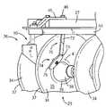
- FIG. 2is an upper right rear perspective view of a blade disk assembly including a disk blade scraper according to a first embodiment of the invention.
- FIG. 3is an upper right rear perspective view of a blade disk assembly including a disk blade scraper according to a second embodiment of the invention.
- FIG. 4is an upper left rear perspective view of a blade disk assembly including a disk blade scraper according to a third embodiment of the invention.
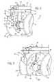
- FIG. 5is an upper left front perspective view of a blade disk assembly including a disk blade scraper according to a fourth embodiment of the invention.
- FIG. 6is an upper left front perspective view of a blade disk assembly including a disk blade scraper according to a fifth embodiment of the invention.
- FIG. 6Ais a top view of the scraper blade of the fifth embodiment of the invention.
- the present inventionis directed to a disk blade scraper.
- FIG. 1there is shown an example tillage implement 10 in which the disk blade scraper of the present invention may be employed.
- the tillage implement 10includes a rigid main frame generally designated 11 that is adapted to be attached at its front to the rear of an agricultural tractor by means of a conventional hitch 12 .
- the main frame 11includes first and second elongated inside frame members 16 , 16 A and first and second outside frame members 17 , 17 A. These inside and outside frame members are affixed to front and rear transverse support members 19 , 19 A. A third transverse support member 20 is interconnected to the forward ends of inside frame members 16 , 16 A. Frame 11 is supported for movement across a field or along a road by wheels 24 .
- disk blade gangs 25 , 26there are two disk blade gangs 25 , 26 at the rear end of the implement. Rigid front gang tubes 27 , 28 are connected to the frame 11 .
- disk bladesare mounted on an elongated horizontal shaft, bolted at each end, and separated by hub spools in known manner. The disk blades can cut and mix soil and residue, or level the soil.
- the disk blade gang 25includes a first embodiment of a disk blade scraper 50 according to the present invention.
- the disk blade gang 25includes horizontal gang tube 27 from which is suspended hanger 31 .
- Hanger 31supports a rotatable horizontal shaft (not shown) in a known manner.
- Disk blades 34are laterally spaced on the horizontal shaft.
- the disk blades 34include a concave surface 35 , an opposite convex surface 36 and a cutting edge 37 for cutting and mixing soil when the tillage implement 10 is pulled through a field.
- Adjacent disk blades 34are laterally spaced on the horizontal shaft by way of hub spools 38 in a known manner.
- the hub spools 38form a circular transition joint 39 with the concave surface 35 on one disk blade 34 and another circular transition joint with the convex surface 36 of the adjacent disk blade.
- an annular depression 41that is formed in a circular region of the concave surface 35 surrounding the transition joint 39 .
- the disk blades 34are typically formed of hardened steel as is well known in the art.
- a blade scraper mounting frame 44is connected rearwardly of the gang tube 27 by way of mounting element 45 and associated fasteners 46 , such as nuts and bolts.
- the blade scraper 50includes a bracket 52 connected to the blade scraper mounting frame 44 , and a separate integral (one piece) scraper blade 54 mounted to the bracket 52 by suitable fasteners 55 (for example, rivets, screws, bolts, spot welds or any other suitable fastening means).
- the scraper blade 54is typically formed from hardened steel.
- the scraper blade 54has a first end 57 adjacent the bracket 52 , a first side 58 and a second opposed side 59 extending downwardly from the first end 57 .
- the first side 58is shorter than the second side 59 in the embodiment shown.
- a scraping end 61extends between the first side 58 and the second side 59 , and the scraping end 61 and the second side 59 of the scraper blade 54 meet at a junction point 63 .
- the scraper blade 54has a thickness in a direction normal to an outer surface 64 of the scraper 54 blade not exceeding a cross-sectional thickness of the first end 57 in the direction normal to an outer surface 64 .
- the bracket 52When the bracket 52 is connected to the blade scraper mounting frame 44 and the scraper blade 54 is mounted to the bracket 52 , the first side 57 of the scraper blade 54 is further from the hub spool 38 than the second side 59 of the scraper blade 54 , and the junction point 63 is adjacent the transition joint 39 between the hub spool 38 and the concave surface 35 of the disk blade 34 .
- the concave surface 35 of the disk blade 34is kept clean from the hub spool 38 on out to the cutting edge 37 of the disk blade 34 by way of the scraper blade 54 .
- the scraper blade 54may be positioned in various relationships with respect to the transition joint 39 between the hub spool 38 and the concave surface 35 of the disk blade 34 .
- the junction point 63 of the scraper blade 54may be located within the annular depression 41 that is formed in a circular region of the concave surface 35 surrounding the transition joint 39 .
- the junction point 63 of the scraper blade 54may contact the transition joint 39 .
- the junction point 63 of the scraper blade 54may be 0.4 inches or less from the transition joint 39 .
- the junction point 63 of the scraper blade 54may be 0.03 to 0.13 inches from the transition joint 39 .
- the scraping end 61 of the scraper blade 54may have a curved edge contoured in a complementary fashion with the concave surface 35 of the disk blade 34 .
- the scraping end 61 of the scraper blade 54may be positioned in various relationships with respect to the concave surface 35 of the disk blade 34 .
- the scraping end 61 of the scraper blade 54may contact the concave surface 35 of the disk blade 34 .
- the scraping end 61 of the scraper blade 54may be 0.4 inches or less from the concave surface 35 of the disk blade 34 .
- the scraping end 61 of the scraper blade 54may be 0.03 to 0.13 inches from the concave surface 35 of the disk blade 34 .
- the blade scraper 50 of FIG. 2provides a blade scraper design with a wider and tapered scraper toward the transition of the hub spool and the disk blade and the scraper point positioned very close to this transition joint.
- FIG. 3there is shown a portion of an alternative disk blade gang 25 (which is shown generally in FIG. 1 ).
- the disk blade gang 25 of FIG. 3includes a second embodiment of a disk blade scraper 70 according to the present invention.
- FIG. 3also shows the first embodiment of a disk blade scraper 50 according to the present invention mounted to the blade scraper mounting frame 44 in order to illustrate that any combination of the disk blade scrapers of the present invention may be used in s disk blade assembly.
- FIG. 3shows the horizontal gang tube 27 , disk blades 34 , the hub spools 38 , the circular transition joint 39 , the annular depression 41 , the blade scraper mounting frame 44 , the mounting element 45 and associated fasteners 46 as shown in FIG. 2 ; therefore, reference can be made to the description of FIG. 2 for an explanation of these elements.
- the blade scraper 70 of FIG. 3includes a bracket 72 connected to the blade scraper mounting frame 44 , and a separate integral (one piece) flat scraper blade 73 mounted to the bracket 72 by suitable fasteners 74 (for example, rivets or bolts, or any other suitable fastening means).
- the scraper blade 73is in the form of a rotating disk having an axis of rotation (typically the same as the longitudinal axis of the fasteners 74 ) and a circumferential edge 76 parallel to the axis of rotation.
- the rotating disk 73is typically formed from hardened steel.
- the circumferential edge 76 of the rotating disk 73is adjacent the transition joint 39 between the hub spool 38 and the concave surface 35 of the disk blade.
- An uppermost edge of the rotating disk 73does not extend above an uppermost edge of the disk blade 34 .
- an outermost edge of the rotating disk 73does not extend beyond an outermost edge of the disk blade 34 .
- the rotating disk 73may be positioned in various relationships with respect to the transition joint 39 between the hub spool 38 and the concave surface 35 of the disk blade 34 .
- the circumferential edge 76 of the rotating disk 73may be located within the annular depression 41 that is formed in a circular region of the concave surface 35 surrounding the transition joint 39 .
- the circumferential edge 76 of the rotating disk 73may contact the transition joint 39 .
- the circumferential edge 76 of the rotating disk 73may be 0.4 inches or less from the transition joint 39 .
- the circumferential edge 76 of the rotating disk 73may be 0.03 to 0.13 inches from the transition joint 39 .
- the blade scraper 70 of FIG. 3provides a design incorporating a round disk cleaner.
- This disk cleaneris affixed to the bracket and positioned from the gang tube in such a way as to run the edge of this disk cleaner in the transition joint of the disk blade and the hub spool.
- the round disk cleanerrotates as disk gang turns and thus becomes self cleaning.
- FIG. 4there is shown a portion of a disk blade gang 26 (which is shown generally in FIG. 1 ).
- the disk blade gang 26 of FIG. 4includes a third embodiment of a disk blade scraper 80 according to the present invention.
- FIG. 4shows a horizontal gang tube 28 , disk blades 34 , hub spools 38 , the circular transition joint 39 , the annular depression 41 , the blade scraper mounting frame 44 , the mounting element 45 and associated fasteners 46 as in FIG. 2 ; therefore, reference can be made to the description of FIG. 2 for an explanation of these elements.
- the blade scraper 80 of FIG. 4includes a bracket 82 connected to the blade scraper mounting frame 44 , and a first separate integral (one piece) elongated bar 83 and a second separate integral (one piece) elongated bar 88 mounted to the bracket 82 by suitable fasteners.
- the elongated bars 83 , 88are shown in the form of elongated cylindrical rods. However, the bars 83 , 88 may have various cross-sectional shapes including, without limitation, a circular cross-section (as shown) and a square cross-section.
- the bars 83 , 88each have a longitudinal axis, and the bars 83 , 88 each have a scraping surface 84 , 89 respectively at an end of the bar farthest from the bracket 82 .
- the scraping surfaces 84 , 89 of the bars 83 , 88have at least a portion at an angle with respect to the longitudinal axis of the bar.
- the scraping surfaceis a flat surface perpendicular to the longitudinal axis of the bar.
- the scraping surfaceis a domed surface.
- the elongated bars 83 , 88are typically formed from hardened steel.
- each bar 83 , 88is mounted to the bracket 82 , and an imaginary straight line including the longitudinal axis of each bar 83 , 88 intersects the hub spool 38 if the imaginary straight line is extended beyond the end of the bar 83 , 88 .
- This arrangementimproves cleaning performance.
- the concave surface 35 of the disk blade 34 and the convex surface 36 of the disk blade 34 aare kept clean from the hub spool 38 on out to the cutting edge 37 of the disk blade by way of bars 83 , 88 .
- the bars 83 , 88may be positioned in various relationships with respect to the transition joint 39 between the hub spool 38 and the concave surface 35 of the disk blade 34 and the convex surface 36 of the disk blade 34 a .
- the scraping surface 84 of the bar 83may be located within the annular depression 41 that is formed in a circular region of the concave surface 35 surrounding the transition joint 39 .
- the scraping surface 84 of the bar 83 and the scraping surface 89 of the bar 88may contact the transition joint 39 .
- the scraping surface 84 of the bar 83 and the scraping surface 89 of the bar 88may be 0.4 inches or less from the transition joint 39 .
- the scraping surface 84 of the bar 83 and the scraping surface 89 of the bar 88may be 0.03 to 0.13 inches from the transition joint 39 .
- the blade scraper 80 of FIG. 4provides a design incorporating a round and or square bar shank. These bars are affixed to the bracket from the gang tube on either the front or backside or both sides of the disk blade. These rods are positioned in such a way that the rod ends are perpendicular to the hub spool center line and disk blade transition joint and the rod ends rub against this transition joint.
- FIG. 5there is shown a portion of disk blade gang 26 (which is shown generally in FIG. 1 ).
- the disk blade gang 26includes a fourth embodiment of a disk blade scraper 90 according to the present invention.
- FIG. 5shows a horizontal gang tube 28 , disk blades 34 , hub spools 38 , the circular transition joint 39 , the blade scraper mounting frame 44 , the mounting element 45 and associated fasteners 46 as in FIG. 2 ; therefore, reference can be made to the description of FIG. 2 for an explanation of these elements.
- the blade scraper mounting frame 44is mounted forwardly of the gang tube 28 .
- the fourth embodiment of the blade scraper 90includes a bracket 92 connected to the blade scraper mounting frame 44 , and a separate integral rectangular (one piece) scraper blade 94 mounted to the bracket 92 by suitable fasteners 95 (for example, rivets, screws, bolts, spot welds or any other suitable fastening means).
- the scraper blade 94is typically formed from hardened steel.
- the scraper blade 94has a first end 97 adjacent the bracket 92 , a first side 98 and a second opposed side 99 extending downwardly from the first end 97 .
- the first side 98is approximately equal in length to the second side 99 in the embodiment shown.
- a scraping surface 91is provided at the second side 99 , and a bottom end 101 and the second side 99 of the scraper blade 94 meet at a junction point 93 .
- the scraper blade 94may be positioned in various relationships with respect to the hub spool 38 .
- the scraper blade 94may be positioned on both sides of a vertical normal line to a center axis of the hub spool 38 .
- the scraping surface 91may be positioned behind the center axis of the hub spool 38 in relation to a direction of movement of the tillage implement 10 .
- the scraper blade 94may be positioned in various relationships with respect to the transition joint 39 between the hub spool 38 and the convex surface 36 of the disk blade 34 .
- the junction point 93 of the scraper blade 94may be located adjacent an annular crimped raised area 41 a that is formed in a circular region of the concave surface 35 surrounding the transition joint 39 .
- the junction point 93 of the scraper blade 94may contact the transition joint 39 .
- the junction point 93 of the scraper blade 94may be 0.4 inches or less from the transition joint 39 .
- the junction point 93 of the scraper blade 94may be 0.03 to 0.13 inches from the transition joint 39 .
- the scraping surface 91 of the scraper blade 94may be positioned in various relationships with respect to the convex surface 36 of the disk blade 34 .
- the scraping surface 91 of the scraper blade 94may contact the convex surface 36 of the disk blade 34 .
- the scraping surface 91 of the scraper blade 94may be 0.4 inches or less from the convex surface 36 of the disk blade 34 .
- the scraping surface 91 of the scraper blade 94may be 0.03 to 0.13 inches from the convex surface 36 of the disk blade 34 .
- the blade scraper 90 of FIG. 5provides a design incorporating a flat scraper blade shaped to fit the contour of the convex backside of the disk blade and clean this side.
- backside disk blade scrapersare affixed to the bracket from the gang tube from the front side of the gang tube. This backside disk scraper is positioned vertically and contacts the disk blade behind the hub spool centerline. The corner of this scraper is positioned very close to the transition joint of the disk blade and the hub spool.
- FIGS. 6 and 6Athere is shown a fifth embodiment of a disk blade scraper 110 according to the present invention.
- the fifth embodiment of the inventionis similar to the fourth embodiment of the blade scraper 90 shown in FIG. 5 albeit with a different scraper blade.
- the scraper blade 194has a first end 197 adjacent the bracket 152 , a first side 198 and a second opposed side 199 extending downwardly from the first end 197 .
- the first side 198 of the scraper blade 194is shorter in length compared to the first side 98 in the embodiment of FIG. 5 .
- a scraping surface 191is provided at the second side 199 of the scraper blade 194 , and a bottom end 201 and the second side 199 of the scraper blade 194 meet at a junction point 193 .
- the scraping surface 191has an inwardly curved edge 155 that may be a radius and that contacts the convex surface 36 of the disk blade 34 .
- the scraping surface 191has a second inwardly curved edge 157 that may be a radius and that contacts the crimp 41 a on the convex surface 36 of the disk blade 36 .
- the edges 155 , 157provide for improved cleaning performance.
- the scraper blade 94 of FIG. 5may also include an inwardly curved edge and a second inwardly curved edge as in the blade scraper 194 of FIGS. 6 and 6A .
- the present inventionprovides a disk blade scraper that provides superior blade cleaning capabilities during field tillage operation in any type of soil conditions.
- the disk blade scraperkeeps the disk blade and hub spool area from building up with dirt/residue such that the disk blade is kept clean from the disk blade and hub spool area on out to the cutting edge of the disk blade.
Landscapes
- Life Sciences & Earth Sciences (AREA)
- Engineering & Computer Science (AREA)
- Mechanical Engineering (AREA)
- Soil Sciences (AREA)
- Environmental Sciences (AREA)
- Soil Working Implements (AREA)
Abstract
Description
Claims (6)
Priority Applications (5)
| Application Number | Priority Date | Filing Date | Title |
|---|---|---|---|
| US10/788,624US7290620B2 (en) | 2004-02-27 | 2004-02-27 | Disk blade scrapers for tillage apparatus |
| US11/856,349US20080000657A1 (en) | 2004-02-27 | 2007-09-17 | Disk Blade Scrapers for Tillage Apparatus |
| US11/856,373US20080000655A1 (en) | 2004-02-27 | 2007-09-17 | Disk Blade Scrapers for Tillage Apparatus |
| US11/856,387US20080000656A1 (en) | 2004-02-27 | 2007-09-17 | Disk Blade Scrapers for Tillage Apparatus |
| US11/856,401US20080006417A1 (en) | 2004-02-27 | 2007-09-17 | Disk Blade Scrapers for Tillage Apparatus |
Applications Claiming Priority (1)
| Application Number | Priority Date | Filing Date | Title |
|---|---|---|---|
| US10/788,624US7290620B2 (en) | 2004-02-27 | 2004-02-27 | Disk blade scrapers for tillage apparatus |
Related Child Applications (4)
| Application Number | Title | Priority Date | Filing Date |
|---|---|---|---|
| US11/856,349DivisionUS20080000657A1 (en) | 2004-02-27 | 2007-09-17 | Disk Blade Scrapers for Tillage Apparatus |
| US11/856,387DivisionUS20080000656A1 (en) | 2004-02-27 | 2007-09-17 | Disk Blade Scrapers for Tillage Apparatus |
| US11/856,373DivisionUS20080000655A1 (en) | 2004-02-27 | 2007-09-17 | Disk Blade Scrapers for Tillage Apparatus |
| US11/856,401DivisionUS20080006417A1 (en) | 2004-02-27 | 2007-09-17 | Disk Blade Scrapers for Tillage Apparatus |
Publications (2)
| Publication Number | Publication Date |
|---|---|
| US20050189126A1 US20050189126A1 (en) | 2005-09-01 |
| US7290620B2true US7290620B2 (en) | 2007-11-06 |
Family
ID=34887036
Family Applications (5)
| Application Number | Title | Priority Date | Filing Date |
|---|---|---|---|
| US10/788,624Expired - LifetimeUS7290620B2 (en) | 2004-02-27 | 2004-02-27 | Disk blade scrapers for tillage apparatus |
| US11/856,387AbandonedUS20080000656A1 (en) | 2004-02-27 | 2007-09-17 | Disk Blade Scrapers for Tillage Apparatus |
| US11/856,401AbandonedUS20080006417A1 (en) | 2004-02-27 | 2007-09-17 | Disk Blade Scrapers for Tillage Apparatus |
| US11/856,373AbandonedUS20080000655A1 (en) | 2004-02-27 | 2007-09-17 | Disk Blade Scrapers for Tillage Apparatus |
| US11/856,349AbandonedUS20080000657A1 (en) | 2004-02-27 | 2007-09-17 | Disk Blade Scrapers for Tillage Apparatus |
Family Applications After (4)
| Application Number | Title | Priority Date | Filing Date |
|---|---|---|---|
| US11/856,387AbandonedUS20080000656A1 (en) | 2004-02-27 | 2007-09-17 | Disk Blade Scrapers for Tillage Apparatus |
| US11/856,401AbandonedUS20080006417A1 (en) | 2004-02-27 | 2007-09-17 | Disk Blade Scrapers for Tillage Apparatus |
| US11/856,373AbandonedUS20080000655A1 (en) | 2004-02-27 | 2007-09-17 | Disk Blade Scrapers for Tillage Apparatus |
| US11/856,349AbandonedUS20080000657A1 (en) | 2004-02-27 | 2007-09-17 | Disk Blade Scrapers for Tillage Apparatus |
Country Status (1)
| Country | Link |
|---|---|
| US (5) | US7290620B2 (en) |
Cited By (5)
| Publication number | Priority date | Publication date | Assignee | Title |
|---|---|---|---|---|
| US9510496B2 (en) | 2013-08-21 | 2016-12-06 | Cnh Industrial America Llc | Tillage implement with scraper/deflector |
| US9516801B2 (en) | 2013-08-21 | 2016-12-13 | Cnh Industrial America Llc | Tillage implement with stop for resilient mounting |
| US9648798B2 (en) | 2013-12-11 | 2017-05-16 | Cnh Industrial America Llc | Flexible wing sections for a field cultivator |
| USD908742S1 (en)* | 2019-04-24 | 2021-01-26 | Kuhn Krause, Inc. | Scraper arm for use with disc harrows |
| US12089515B2 (en) | 2020-12-03 | 2024-09-17 | Cnh Industrial America Llc | Monitoring system for an agricultural implement |
Families Citing this family (2)
| Publication number | Priority date | Publication date | Assignee | Title |
|---|---|---|---|---|
| US20110192619A1 (en)* | 2010-02-09 | 2011-08-11 | Jerry Harris | Tractor-propelled cultivator having flexible weeder blade |
| HUE034260T2 (en)* | 2014-07-23 | 2018-01-29 | Kverneland Group Les Landes Genusson | Cutting unit |
Citations (43)
| Publication number | Priority date | Publication date | Assignee | Title |
|---|---|---|---|---|
| US358246A (en)* | 1887-02-22 | Cutting-disk for seeding-machines | ||
| US377213A (en) | 1888-01-31 | Harrow | ||
| US523508A (en)* | 1894-07-24 | Disk harrow | ||
| US662981A (en) | 1900-06-04 | 1900-12-04 | Smith S Sims | Disk harrow. |
| US663436A (en) | 1900-08-30 | 1900-12-11 | Parlin & Orendorff Co | Scraper for soil-cutting disks. |
| US785865A (en)* | 1904-09-06 | 1905-03-28 | Spencer E Davis | Scraper for disk drills. |
| US808021A (en)* | 1905-09-02 | 1905-12-19 | Spencer E Davis | Scraper for disk drills. |
| US831505A (en) | 1905-12-04 | 1906-09-18 | Galesburg Coulter Disc Co | Cleaner for disk harrows. |
| US856033A (en) | 1906-04-23 | 1907-06-04 | Joseph L Crisler | Harrow attachment for plows. |
| US935680A (en) | 1908-11-30 | 1909-10-05 | Bucher & Gibbs Plow Company | Disk-harrow scraper. |
| US1017318A (en) | 1911-01-03 | 1912-02-13 | Monitor Drill Co | Grain-drill. |
| US1096478A (en)* | 1913-09-27 | 1914-05-12 | Edwin Weller | Disk plow. |
| US1160638A (en) | 1912-07-12 | 1915-11-16 | Peoria Drill & Seeder Company | Scraper for disks. |
| US1168594A (en)* | 1915-10-01 | 1916-01-18 | Frederick Berendes | Disk plow. |
| US1204306A (en) | 1916-02-03 | 1916-11-07 | Beaver Dam Mfg Co | Supporting mechanism for scraping-blades. |
| US1220014A (en) | 1916-02-07 | 1917-03-20 | Frank Sherwin | Attachment for planters. |
| US1260752A (en) | 1916-11-16 | 1918-03-26 | James Oliver Casaday | Plow-colter. |
| US1321040A (en) | 1919-11-04 | Disk plow | ||
| US1391593A (en)* | 1920-10-23 | 1921-09-20 | Sweeting Claude Clarence | Plow |
| US1410813A (en) | 1921-08-15 | 1922-03-28 | Kammeyer John | Disk scraper for agricultural machines |
| US1472209A (en) | 1922-04-19 | 1923-10-30 | Oliver Chilled Plow Works | Agricultural implement |
| US1663239A (en)* | 1928-03-20 | Frederick a | ||
| US1791462A (en) | 1928-06-05 | 1931-02-03 | Bermel Anthony John | Cultivator-disk cleaner |
| US1819292A (en) | 1927-07-23 | 1931-08-18 | Case Co J I | Disk plow |
| US1982157A (en) | 1933-09-30 | 1934-11-27 | Gandrup Vernon | Agricultural implement |
| US2353790A (en) | 1942-04-24 | 1944-07-18 | Minneapolis Moline Power Co | Scraper mechanism |
| US2805534A (en) | 1953-06-01 | 1957-09-10 | Robertson Jackson Perry | Composite fitting for folding lift-type disc harrow |
| US2901049A (en) | 1957-06-03 | 1959-08-25 | Haai Kermit M De | Scraper device for a farm disc |
| US3139938A (en) | 1962-09-04 | 1964-07-07 | Int Harvester Co | Scraper |
| US3261411A (en)* | 1964-12-29 | 1966-07-19 | Deere & Co | Disk scraper |
| US3438448A (en) | 1966-03-08 | 1969-04-15 | Massey Ferguson Inc | Disc scraper |
| US3833067A (en) | 1972-10-30 | 1974-09-03 | Deere & Co | Spring biased scraper for disk implements |
| US4008770A (en) | 1975-04-10 | 1977-02-22 | Harold G. Walker | Scraper assembly for ground tillage implement discs |
| US4034688A (en) | 1975-11-24 | 1977-07-12 | Ernst Arnold E | Disc scraping apparatus |
| US4127179A (en) | 1976-11-22 | 1978-11-28 | International Harvester Company | Scraper mechanism for disk gang harrows |
| US4206817A (en) | 1978-09-18 | 1980-06-10 | Galen Bowerman | Scraper blade mechanism for double disc |
| US4245706A (en) | 1978-08-17 | 1981-01-20 | Dmi, Inc. | One-pass complete tillage system |
| US4330041A (en) | 1980-07-28 | 1982-05-18 | Krause Plow Corporation | Scraper assembly |
| US4333535A (en) | 1980-07-25 | 1982-06-08 | Deere & Company | Disc standard assembly |
| US4603746A (en) | 1984-07-19 | 1986-08-05 | Deere & Co | Disk blade scraper |
| US4669550A (en)* | 1985-08-30 | 1987-06-02 | Sittre Wayne R | Rotary scraper for planter disks |
| US5267619A (en) | 1992-01-27 | 1993-12-07 | Case Corporation | Disk harrow assembly |
| US6557646B1 (en) | 2002-02-06 | 2003-05-06 | Case, Llc | Mulch-till ripper |
Family Cites Families (26)
| Publication number | Priority date | Publication date | Assignee | Title |
|---|---|---|---|---|
| US492385A (en)* | 1893-02-28 | Scraper for disk harrows | ||
| US347744A (en)* | 1886-08-17 | stoddard | ||
| US493182A (en)* | 1893-03-07 | Disk harrow | ||
| US718825A (en)* | 1902-06-21 | 1903-01-20 | Spencer E Davis | Disk drill. |
| US760742A (en)* | 1903-11-30 | 1904-05-24 | D M Osborne And Company | Disk harrow. |
| US849993A (en)* | 1906-11-19 | 1907-04-09 | Galesburg Coulter Disc Co | Disk-harrow scraper. |
| US885080A (en)* | 1907-03-04 | 1908-04-21 | Thomas Mfg Company | Disk drill. |
| US989748A (en)* | 1910-04-30 | 1911-04-18 | Charles E Adams | Cleaner for disk harrows. |
| US1087789A (en)* | 1912-06-03 | 1914-02-17 | Henry T Lauterbach | Disk colter. |
| US1087790A (en)* | 1912-10-17 | 1914-02-17 | Henry T Lauterbach | Disk colter. |
| US1080677A (en)* | 1913-03-31 | 1913-12-09 | Herman J Boelter | Colter-cleaner. |
| US1206930A (en)* | 1915-03-17 | 1916-12-05 | Int Harvester Co | Disk harrow. |
| US1225904A (en)* | 1916-09-30 | 1917-05-15 | Deere & Mansur Company | Harrow. |
| US1298209A (en)* | 1918-03-14 | 1919-03-25 | Oliver Chilled Plow Works | Disk plow. |
| US1456581A (en)* | 1918-04-24 | 1923-05-29 | Deere & Co | Disk cultivator |
| US1648381A (en)* | 1924-06-16 | 1927-11-08 | John H Flatley | Scraper for harrow disks and means for operating the same |
| US2045762A (en)* | 1935-03-05 | 1936-06-30 | Dempster Mill Mfg Company | Cleaning and polishing pad for disks |
| US2468278A (en)* | 1944-07-06 | 1949-04-26 | John Deere Killerfer Company | Disk gang assembly |
| US2442727A (en)* | 1944-12-07 | 1948-06-01 | John Deere Van Brunt Co | Scraper for grain drill disks |
| US2688831A (en)* | 1950-02-11 | 1954-09-14 | Burch Plow Works Inc | Multiple-gang disk harrow |
| US2730940A (en)* | 1953-07-07 | 1956-01-17 | Be Ge Mfg Co | Scraper blade for reversible disc plows |
| US3499495A (en)* | 1968-03-29 | 1970-03-10 | Waldo H Pust | Crop seed planting device |
| US4492272A (en)* | 1982-03-15 | 1985-01-08 | Deere & Company | Tillage implement and improved gang assembly therefor |
| US4489787A (en)* | 1982-11-15 | 1984-12-25 | William A. Russ | Angled rolling knives and method of weeding |
| CA2250677A1 (en)* | 1998-10-20 | 2000-04-20 | Dean Jay Mayerle | Fertilizer/soybean opener (fso) |
| US6659193B1 (en)* | 2002-06-28 | 2003-12-09 | Morris Industries Ltd. | Depth adjustment mechanism for farm implements |
- 2004
- 2004-02-27USUS10/788,624patent/US7290620B2/ennot_activeExpired - Lifetime
- 2007
- 2007-09-17USUS11/856,387patent/US20080000656A1/ennot_activeAbandoned
- 2007-09-17USUS11/856,401patent/US20080006417A1/ennot_activeAbandoned
- 2007-09-17USUS11/856,373patent/US20080000655A1/ennot_activeAbandoned
- 2007-09-17USUS11/856,349patent/US20080000657A1/ennot_activeAbandoned
Patent Citations (43)
| Publication number | Priority date | Publication date | Assignee | Title |
|---|---|---|---|---|
| US1321040A (en) | 1919-11-04 | Disk plow | ||
| US377213A (en) | 1888-01-31 | Harrow | ||
| US523508A (en)* | 1894-07-24 | Disk harrow | ||
| US1663239A (en)* | 1928-03-20 | Frederick a | ||
| US358246A (en)* | 1887-02-22 | Cutting-disk for seeding-machines | ||
| US662981A (en) | 1900-06-04 | 1900-12-04 | Smith S Sims | Disk harrow. |
| US663436A (en) | 1900-08-30 | 1900-12-11 | Parlin & Orendorff Co | Scraper for soil-cutting disks. |
| US785865A (en)* | 1904-09-06 | 1905-03-28 | Spencer E Davis | Scraper for disk drills. |
| US808021A (en)* | 1905-09-02 | 1905-12-19 | Spencer E Davis | Scraper for disk drills. |
| US831505A (en) | 1905-12-04 | 1906-09-18 | Galesburg Coulter Disc Co | Cleaner for disk harrows. |
| US856033A (en) | 1906-04-23 | 1907-06-04 | Joseph L Crisler | Harrow attachment for plows. |
| US935680A (en) | 1908-11-30 | 1909-10-05 | Bucher & Gibbs Plow Company | Disk-harrow scraper. |
| US1017318A (en) | 1911-01-03 | 1912-02-13 | Monitor Drill Co | Grain-drill. |
| US1160638A (en) | 1912-07-12 | 1915-11-16 | Peoria Drill & Seeder Company | Scraper for disks. |
| US1096478A (en)* | 1913-09-27 | 1914-05-12 | Edwin Weller | Disk plow. |
| US1168594A (en)* | 1915-10-01 | 1916-01-18 | Frederick Berendes | Disk plow. |
| US1204306A (en) | 1916-02-03 | 1916-11-07 | Beaver Dam Mfg Co | Supporting mechanism for scraping-blades. |
| US1220014A (en) | 1916-02-07 | 1917-03-20 | Frank Sherwin | Attachment for planters. |
| US1260752A (en) | 1916-11-16 | 1918-03-26 | James Oliver Casaday | Plow-colter. |
| US1391593A (en)* | 1920-10-23 | 1921-09-20 | Sweeting Claude Clarence | Plow |
| US1410813A (en) | 1921-08-15 | 1922-03-28 | Kammeyer John | Disk scraper for agricultural machines |
| US1472209A (en) | 1922-04-19 | 1923-10-30 | Oliver Chilled Plow Works | Agricultural implement |
| US1819292A (en) | 1927-07-23 | 1931-08-18 | Case Co J I | Disk plow |
| US1791462A (en) | 1928-06-05 | 1931-02-03 | Bermel Anthony John | Cultivator-disk cleaner |
| US1982157A (en) | 1933-09-30 | 1934-11-27 | Gandrup Vernon | Agricultural implement |
| US2353790A (en) | 1942-04-24 | 1944-07-18 | Minneapolis Moline Power Co | Scraper mechanism |
| US2805534A (en) | 1953-06-01 | 1957-09-10 | Robertson Jackson Perry | Composite fitting for folding lift-type disc harrow |
| US2901049A (en) | 1957-06-03 | 1959-08-25 | Haai Kermit M De | Scraper device for a farm disc |
| US3139938A (en) | 1962-09-04 | 1964-07-07 | Int Harvester Co | Scraper |
| US3261411A (en)* | 1964-12-29 | 1966-07-19 | Deere & Co | Disk scraper |
| US3438448A (en) | 1966-03-08 | 1969-04-15 | Massey Ferguson Inc | Disc scraper |
| US3833067A (en) | 1972-10-30 | 1974-09-03 | Deere & Co | Spring biased scraper for disk implements |
| US4008770A (en) | 1975-04-10 | 1977-02-22 | Harold G. Walker | Scraper assembly for ground tillage implement discs |
| US4034688A (en) | 1975-11-24 | 1977-07-12 | Ernst Arnold E | Disc scraping apparatus |
| US4127179A (en) | 1976-11-22 | 1978-11-28 | International Harvester Company | Scraper mechanism for disk gang harrows |
| US4245706A (en) | 1978-08-17 | 1981-01-20 | Dmi, Inc. | One-pass complete tillage system |
| US4206817A (en) | 1978-09-18 | 1980-06-10 | Galen Bowerman | Scraper blade mechanism for double disc |
| US4333535A (en) | 1980-07-25 | 1982-06-08 | Deere & Company | Disc standard assembly |
| US4330041A (en) | 1980-07-28 | 1982-05-18 | Krause Plow Corporation | Scraper assembly |
| US4603746A (en) | 1984-07-19 | 1986-08-05 | Deere & Co | Disk blade scraper |
| US4669550A (en)* | 1985-08-30 | 1987-06-02 | Sittre Wayne R | Rotary scraper for planter disks |
| US5267619A (en) | 1992-01-27 | 1993-12-07 | Case Corporation | Disk harrow assembly |
| US6557646B1 (en) | 2002-02-06 | 2003-05-06 | Case, Llc | Mulch-till ripper |
Cited By (8)
| Publication number | Priority date | Publication date | Assignee | Title |
|---|---|---|---|---|
| US9510496B2 (en) | 2013-08-21 | 2016-12-06 | Cnh Industrial America Llc | Tillage implement with scraper/deflector |
| US9516801B2 (en) | 2013-08-21 | 2016-12-13 | Cnh Industrial America Llc | Tillage implement with stop for resilient mounting |
| US9648798B2 (en) | 2013-12-11 | 2017-05-16 | Cnh Industrial America Llc | Flexible wing sections for a field cultivator |
| US9872422B2 (en) | 2013-12-11 | 2018-01-23 | Cnh Industrial America Llc | Flexible wing sections for a field cultivator |
| US10257972B2 (en) | 2013-12-11 | 2019-04-16 | Cnh Industrial America Llc | Flexible wing sections for a field cultivator |
| US10412876B2 (en) | 2013-12-11 | 2019-09-17 | Cnh Industrial America Llc | Flexible wing sections for a field cultivator |
| USD908742S1 (en)* | 2019-04-24 | 2021-01-26 | Kuhn Krause, Inc. | Scraper arm for use with disc harrows |
| US12089515B2 (en) | 2020-12-03 | 2024-09-17 | Cnh Industrial America Llc | Monitoring system for an agricultural implement |
Also Published As
| Publication number | Publication date |
|---|---|
| US20080000656A1 (en) | 2008-01-03 |
| US20080000655A1 (en) | 2008-01-03 |
| US20080000657A1 (en) | 2008-01-03 |
| US20050189126A1 (en) | 2005-09-01 |
| US20080006417A1 (en) | 2008-01-10 |
Similar Documents
| Publication | Publication Date | Title |
|---|---|---|
| US20080000657A1 (en) | Disk Blade Scrapers for Tillage Apparatus | |
| US20200146196A1 (en) | Vertical tillage system | |
| US20180288931A1 (en) | Agricultural implement with treader-reel finishing attachment | |
| US5632343A (en) | Soil deflecting and leveling reel | |
| US9313937B2 (en) | Apparatus and method for soil tillage and levelling | |
| US8074728B2 (en) | Shallow disc blade vertical tillage system | |
| US9814171B2 (en) | Walking beam closing disk assembly | |
| US9510496B2 (en) | Tillage implement with scraper/deflector | |
| US20160168813A1 (en) | Implement apparatus and systems for displacing ground material | |
| US10531602B2 (en) | Implements for displacing ground material | |
| US8074727B2 (en) | Symmetrical path vertical tillage system and method | |
| JP5099779B2 (en) | Rough tillage work machine | |
| US7143837B2 (en) | Soil conditioning rotary reel for secondary tillage operations | |
| US2357528A (en) | Farming implement | |
| US10138936B2 (en) | Agricultural rolling basket bearing assembly | |
| US2323460A (en) | Rotary subsoiler | |
| CA2809708C (en) | Apparatus and method for soil tillage and levelling | |
| JP2023168569A (en) | Agricultural working machine | |
| US10104823B2 (en) | Vertical tillage scraper | |
| US5040617A (en) | Active harrow | |
| CN115462197A (en) | Submersible combined leveling machine | |
| US7143836B2 (en) | Soil conditioning rotary reel for primary tillage operations | |
| US1632958A (en) | Cultivator blade | |
| JP2009082080A (en) | Rotary of tractor | |
| JPH0795801A (en) | Bottom plow |
Legal Events
| Date | Code | Title | Description |
|---|---|---|---|
| AS | Assignment | Owner name:CASE AMERICA, LLC, WISCONSIN Free format text:ASSIGNMENT OF ASSIGNORS INTEREST;ASSIGNORS:COOPER, TROY L.;KUEBLER, MARVIN D.;GERBER, RICKEY L.;REEL/FRAME:015032/0898 Effective date:20040225 | |
| AS | Assignment | Owner name:CNH AMERICA LLC, WISCONSIN Free format text:ASSIGNMENT OF ASSIGNORS INTEREST;ASSIGNORS:COOPER, TROY L;KUEBLER, MARVIN D;GERBER, RICKEY L;REEL/FRAME:019829/0994;SIGNING DATES FROM 20040826 TO 20040830 | |
| STCF | Information on status: patent grant | Free format text:PATENTED CASE | |
| AS | Assignment | Owner name:BLUE LEAF I.P. INC., DELAWARE Free format text:ASSIGNMENT OF ASSIGNORS INTEREST;ASSIGNOR:CNH AMERICA LLC;REEL/FRAME:020227/0024 Effective date:20071210 Owner name:BLUE LEAF I.P. INC.,DELAWARE Free format text:ASSIGNMENT OF ASSIGNORS INTEREST;ASSIGNOR:CNH AMERICA LLC;REEL/FRAME:020227/0024 Effective date:20071210 | |
| FPAY | Fee payment | Year of fee payment:4 | |
| FPAY | Fee payment | Year of fee payment:8 | |
| MAFP | Maintenance fee payment | Free format text:PAYMENT OF MAINTENANCE FEE, 12TH YEAR, LARGE ENTITY (ORIGINAL EVENT CODE: M1553); ENTITY STATUS OF PATENT OWNER: LARGE ENTITY Year of fee payment:12 |