US7289887B2 - Systems and methods for remote power management using IEEE 802 based wireless communication links - Google Patents
Systems and methods for remote power management using IEEE 802 based wireless communication linksDownload PDFInfo
- Publication number
- US7289887B2 US7289887B2US10/729,532US72953203AUS7289887B2US 7289887 B2US7289887 B2US 7289887B2US 72953203 AUS72953203 AUS 72953203AUS 7289887 B2US7289887 B2US 7289887B2
- Authority
- US
- United States
- Prior art keywords
- opp
- end device
- power
- host
- energy
- Prior art date
- Legal status (The legal status is an assumption and is not a legal conclusion. Google has not performed a legal analysis and makes no representation as to the accuracy of the status listed.)
- Expired - Fee Related, expires
Links
- 238000004891communicationMethods0.000titleclaimsabstractdescription85
- 238000000034methodMethods0.000titleclaimsabstractdescription49
- 230000004913activationEffects0.000claimsdescription32
- 238000009826distributionMethods0.000claimsdescription29
- 230000004044responseEffects0.000claimsdescription27
- 238000004378air conditioningMethods0.000claimsdescription10
- 238000010438heat treatmentMethods0.000claims1
- 230000006698inductionEffects0.000claims1
- 230000003213activating effectEffects0.000abstractdescription2
- 230000009467reductionEffects0.000description40
- 230000006870functionEffects0.000description35
- 238000005516engineering processMethods0.000description17
- 230000005540biological transmissionEffects0.000description15
- 230000009849deactivationEffects0.000description15
- 230000008569processEffects0.000description14
- 238000012545processingMethods0.000description14
- 239000007789gasSubstances0.000description11
- 238000001228spectrumMethods0.000description11
- 230000001105regulatory effectEffects0.000description10
- 238000013459approachMethods0.000description9
- 238000013475authorizationMethods0.000description7
- 230000008901benefitEffects0.000description7
- 230000033228biological regulationEffects0.000description7
- 230000001276controlling effectEffects0.000description7
- 230000002747voluntary effectEffects0.000description7
- 230000001413cellular effectEffects0.000description6
- XLYOFNOQVPJJNP-UHFFFAOYSA-NwaterSubstancesOXLYOFNOQVPJJNP-UHFFFAOYSA-N0.000description5
- 230000000694effectsEffects0.000description4
- 238000012546transferMethods0.000description4
- 238000011161developmentMethods0.000description3
- 238000005259measurementMethods0.000description3
- 230000000717retained effectEffects0.000description3
- 238000005096rolling processMethods0.000description3
- 239000007787solidSubstances0.000description3
- 230000003466anti-cipated effectEffects0.000description2
- 230000000977initiatory effectEffects0.000description2
- 230000003993interactionEffects0.000description2
- 238000004519manufacturing processMethods0.000description2
- 238000013507mappingMethods0.000description2
- 239000000463materialSubstances0.000description2
- 230000007246mechanismEffects0.000description2
- VNWKTOKETHGBQD-UHFFFAOYSA-NmethaneChemical compoundCVNWKTOKETHGBQD-UHFFFAOYSA-N0.000description2
- XRQVVFIEYAHKBV-OGYJWPHRSA-Nopp protocolChemical compoundCNNCC1=CC=C(C(=O)NC(C)C)C=C1.O=C1C=C[C@]2(C)[C@H]3C(=O)C[C@](C)([C@@](CC4)(O)C(=O)CO)[C@@H]4[C@@H]3CCC2=C1.C([C@H](C[C@]1(C(=O)OC)C=2C(=C3C([C@]45[C@H]([C@@]([C@H](OC(C)=O)[C@]6(CC)C=CCN([C@H]56)CC4)(O)C(=O)OC)N3C=O)=CC=2)OC)C[C@@](C2)(O)CC)N2CCC2=C1NC1=CC=CC=C21XRQVVFIEYAHKBV-OGYJWPHRSA-N0.000description2
- 230000000737periodic effectEffects0.000description2
- 235000008694Humulus lupulusNutrition0.000description1
- 230000002159abnormal effectEffects0.000description1
- 230000009471actionEffects0.000description1
- 230000003190augmentative effectEffects0.000description1
- 238000006243chemical reactionMethods0.000description1
- 239000003245coalSubstances0.000description1
- 230000007423decreaseEffects0.000description1
- 230000003247decreasing effectEffects0.000description1
- 239000002283diesel fuelSubstances0.000description1
- 238000005265energy consumptionMethods0.000description1
- 230000002349favourable effectEffects0.000description1
- 239000012530fluidSubstances0.000description1
- 239000000446fuelSubstances0.000description1
- 239000003502gasolineSubstances0.000description1
- 239000011521glassSubstances0.000description1
- 238000010348incorporationMethods0.000description1
- 238000009434installationMethods0.000description1
- 230000010354integrationEffects0.000description1
- 239000003350keroseneSubstances0.000description1
- 239000007788liquidSubstances0.000description1
- 239000002184metalSubstances0.000description1
- 238000012544monitoring processMethods0.000description1
- 230000008450motivationEffects0.000description1
- 239000003345natural gasSubstances0.000description1
- 239000003921oilSubstances0.000description1
- 229920001690polydopaminePolymers0.000description1
- 238000010248power generationMethods0.000description1
- 239000002243precursorSubstances0.000description1
- 238000004886process controlMethods0.000description1
- 239000004065semiconductorSubstances0.000description1
- 230000011664signalingEffects0.000description1
- 238000003860storageMethods0.000description1
- 230000001960triggered effectEffects0.000description1
- 238000012795verificationMethods0.000description1
- 230000000007visual effectEffects0.000description1
Images


Classifications
- G—PHYSICS
- G01—MEASURING; TESTING
- G01D—MEASURING NOT SPECIALLY ADAPTED FOR A SPECIFIC VARIABLE; ARRANGEMENTS FOR MEASURING TWO OR MORE VARIABLES NOT COVERED IN A SINGLE OTHER SUBCLASS; TARIFF METERING APPARATUS; MEASURING OR TESTING NOT OTHERWISE PROVIDED FOR
- G01D4/00—Tariff metering apparatus
- G01D4/002—Remote reading of utility meters
- G01D4/004—Remote reading of utility meters to a fixed location
- G—PHYSICS
- G01—MEASURING; TESTING
- G01R—MEASURING ELECTRIC VARIABLES; MEASURING MAGNETIC VARIABLES
- G01R22/00—Arrangements for measuring time integral of electric power or current, e.g. electricity meters
- G01R22/06—Arrangements for measuring time integral of electric power or current, e.g. electricity meters by electronic methods
- G01R22/061—Details of electronic electricity meters
- G01R22/063—Details of electronic electricity meters related to remote communication
- H—ELECTRICITY
- H04—ELECTRIC COMMUNICATION TECHNIQUE
- H04L—TRANSMISSION OF DIGITAL INFORMATION, e.g. TELEGRAPHIC COMMUNICATION
- H04L67/00—Network arrangements or protocols for supporting network services or applications
- H04L67/01—Protocols
- H04L67/04—Protocols specially adapted for terminals or networks with limited capabilities; specially adapted for terminal portability
- H—ELECTRICITY
- H04—ELECTRIC COMMUNICATION TECHNIQUE
- H04L—TRANSMISSION OF DIGITAL INFORMATION, e.g. TELEGRAPHIC COMMUNICATION
- H04L67/00—Network arrangements or protocols for supporting network services or applications
- H04L67/01—Protocols
- H04L67/12—Protocols specially adapted for proprietary or special-purpose networking environments, e.g. medical networks, sensor networks, networks in vehicles or remote metering networks
- H04L67/125—Protocols specially adapted for proprietary or special-purpose networking environments, e.g. medical networks, sensor networks, networks in vehicles or remote metering networks involving control of end-device applications over a network
- H—ELECTRICITY
- H02—GENERATION; CONVERSION OR DISTRIBUTION OF ELECTRIC POWER
- H02J—CIRCUIT ARRANGEMENTS OR SYSTEMS FOR SUPPLYING OR DISTRIBUTING ELECTRIC POWER; SYSTEMS FOR STORING ELECTRIC ENERGY
- H02J13/00—Circuit arrangements for providing remote indication of network conditions, e.g. an instantaneous record of the open or closed condition of each circuitbreaker in the network; Circuit arrangements for providing remote control of switching means in a power distribution network, e.g. switching in and out of current consumers by using a pulse code signal carried by the network
- H02J13/00004—Circuit arrangements for providing remote indication of network conditions, e.g. an instantaneous record of the open or closed condition of each circuitbreaker in the network; Circuit arrangements for providing remote control of switching means in a power distribution network, e.g. switching in and out of current consumers by using a pulse code signal carried by the network characterised by the power network being locally controlled
- H—ELECTRICITY
- H02—GENERATION; CONVERSION OR DISTRIBUTION OF ELECTRIC POWER
- H02J—CIRCUIT ARRANGEMENTS OR SYSTEMS FOR SUPPLYING OR DISTRIBUTING ELECTRIC POWER; SYSTEMS FOR STORING ELECTRIC ENERGY
- H02J13/00—Circuit arrangements for providing remote indication of network conditions, e.g. an instantaneous record of the open or closed condition of each circuitbreaker in the network; Circuit arrangements for providing remote control of switching means in a power distribution network, e.g. switching in and out of current consumers by using a pulse code signal carried by the network
- H02J13/00006—Circuit arrangements for providing remote indication of network conditions, e.g. an instantaneous record of the open or closed condition of each circuitbreaker in the network; Circuit arrangements for providing remote control of switching means in a power distribution network, e.g. switching in and out of current consumers by using a pulse code signal carried by the network characterised by information or instructions transport means between the monitoring, controlling or managing units and monitored, controlled or operated power network element or electrical equipment
- H02J13/00022—Circuit arrangements for providing remote indication of network conditions, e.g. an instantaneous record of the open or closed condition of each circuitbreaker in the network; Circuit arrangements for providing remote control of switching means in a power distribution network, e.g. switching in and out of current consumers by using a pulse code signal carried by the network characterised by information or instructions transport means between the monitoring, controlling or managing units and monitored, controlled or operated power network element or electrical equipment using wireless data transmission
- H02J13/00024—Circuit arrangements for providing remote indication of network conditions, e.g. an instantaneous record of the open or closed condition of each circuitbreaker in the network; Circuit arrangements for providing remote control of switching means in a power distribution network, e.g. switching in and out of current consumers by using a pulse code signal carried by the network characterised by information or instructions transport means between the monitoring, controlling or managing units and monitored, controlled or operated power network element or electrical equipment using wireless data transmission by means of mobile telephony
- H—ELECTRICITY
- H02—GENERATION; CONVERSION OR DISTRIBUTION OF ELECTRIC POWER
- H02J—CIRCUIT ARRANGEMENTS OR SYSTEMS FOR SUPPLYING OR DISTRIBUTING ELECTRIC POWER; SYSTEMS FOR STORING ELECTRIC ENERGY
- H02J13/00—Circuit arrangements for providing remote indication of network conditions, e.g. an instantaneous record of the open or closed condition of each circuitbreaker in the network; Circuit arrangements for providing remote control of switching means in a power distribution network, e.g. switching in and out of current consumers by using a pulse code signal carried by the network
- H02J13/00006—Circuit arrangements for providing remote indication of network conditions, e.g. an instantaneous record of the open or closed condition of each circuitbreaker in the network; Circuit arrangements for providing remote control of switching means in a power distribution network, e.g. switching in and out of current consumers by using a pulse code signal carried by the network characterised by information or instructions transport means between the monitoring, controlling or managing units and monitored, controlled or operated power network element or electrical equipment
- H02J13/00022—Circuit arrangements for providing remote indication of network conditions, e.g. an instantaneous record of the open or closed condition of each circuitbreaker in the network; Circuit arrangements for providing remote control of switching means in a power distribution network, e.g. switching in and out of current consumers by using a pulse code signal carried by the network characterised by information or instructions transport means between the monitoring, controlling or managing units and monitored, controlled or operated power network element or electrical equipment using wireless data transmission
- H02J13/00026—Circuit arrangements for providing remote indication of network conditions, e.g. an instantaneous record of the open or closed condition of each circuitbreaker in the network; Circuit arrangements for providing remote control of switching means in a power distribution network, e.g. switching in and out of current consumers by using a pulse code signal carried by the network characterised by information or instructions transport means between the monitoring, controlling or managing units and monitored, controlled or operated power network element or electrical equipment using wireless data transmission involving a local wireless network, e.g. Wi-Fi, ZigBee or Bluetooth
- H—ELECTRICITY
- H02—GENERATION; CONVERSION OR DISTRIBUTION OF ELECTRIC POWER
- H02J—CIRCUIT ARRANGEMENTS OR SYSTEMS FOR SUPPLYING OR DISTRIBUTING ELECTRIC POWER; SYSTEMS FOR STORING ELECTRIC ENERGY
- H02J2310/00—The network for supplying or distributing electric power characterised by its spatial reach or by the load
- H02J2310/10—The network having a local or delimited stationary reach
- H02J2310/12—The local stationary network supplying a household or a building
- H02J2310/14—The load or loads being home appliances
- H—ELECTRICITY
- H02—GENERATION; CONVERSION OR DISTRIBUTION OF ELECTRIC POWER
- H02J—CIRCUIT ARRANGEMENTS OR SYSTEMS FOR SUPPLYING OR DISTRIBUTING ELECTRIC POWER; SYSTEMS FOR STORING ELECTRIC ENERGY
- H02J3/00—Circuit arrangements for AC mains or AC distribution networks
- H02J3/12—Circuit arrangements for AC mains or AC distribution networks for adjusting voltage in AC networks by changing a characteristic of the network load
- H02J3/14—Circuit arrangements for AC mains or AC distribution networks for adjusting voltage in AC networks by changing a characteristic of the network load by switching loads on to, or off from, network, e.g. progressively balanced loading
- H—ELECTRICITY
- H04—ELECTRIC COMMUNICATION TECHNIQUE
- H04W—WIRELESS COMMUNICATION NETWORKS
- H04W4/00—Services specially adapted for wireless communication networks; Facilities therefor
- H—ELECTRICITY
- H04—ELECTRIC COMMUNICATION TECHNIQUE
- H04W—WIRELESS COMMUNICATION NETWORKS
- H04W84/00—Network topologies
- H04W84/02—Hierarchically pre-organised networks, e.g. paging networks, cellular networks, WLAN [Wireless Local Area Network] or WLL [Wireless Local Loop]
- H04W84/10—Small scale networks; Flat hierarchical networks
- H04W84/12—WLAN [Wireless Local Area Networks]
- Y—GENERAL TAGGING OF NEW TECHNOLOGICAL DEVELOPMENTS; GENERAL TAGGING OF CROSS-SECTIONAL TECHNOLOGIES SPANNING OVER SEVERAL SECTIONS OF THE IPC; TECHNICAL SUBJECTS COVERED BY FORMER USPC CROSS-REFERENCE ART COLLECTIONS [XRACs] AND DIGESTS
- Y02—TECHNOLOGIES OR APPLICATIONS FOR MITIGATION OR ADAPTATION AGAINST CLIMATE CHANGE
- Y02B—CLIMATE CHANGE MITIGATION TECHNOLOGIES RELATED TO BUILDINGS, e.g. HOUSING, HOUSE APPLIANCES OR RELATED END-USER APPLICATIONS
- Y02B70/00—Technologies for an efficient end-user side electric power management and consumption
- Y02B70/30—Systems integrating technologies related to power network operation and communication or information technologies for improving the carbon footprint of the management of residential or tertiary loads, i.e. smart grids as climate change mitigation technology in the buildings sector, including also the last stages of power distribution and the control, monitoring or operating management systems at local level
- Y02B70/3225—Demand response systems, e.g. load shedding, peak shaving
- Y—GENERAL TAGGING OF NEW TECHNOLOGICAL DEVELOPMENTS; GENERAL TAGGING OF CROSS-SECTIONAL TECHNOLOGIES SPANNING OVER SEVERAL SECTIONS OF THE IPC; TECHNICAL SUBJECTS COVERED BY FORMER USPC CROSS-REFERENCE ART COLLECTIONS [XRACs] AND DIGESTS
- Y02—TECHNOLOGIES OR APPLICATIONS FOR MITIGATION OR ADAPTATION AGAINST CLIMATE CHANGE
- Y02B—CLIMATE CHANGE MITIGATION TECHNOLOGIES RELATED TO BUILDINGS, e.g. HOUSING, HOUSE APPLIANCES OR RELATED END-USER APPLICATIONS
- Y02B90/00—Enabling technologies or technologies with a potential or indirect contribution to GHG emissions mitigation
- Y02B90/20—Smart grids as enabling technology in buildings sector
- Y—GENERAL TAGGING OF NEW TECHNOLOGICAL DEVELOPMENTS; GENERAL TAGGING OF CROSS-SECTIONAL TECHNOLOGIES SPANNING OVER SEVERAL SECTIONS OF THE IPC; TECHNICAL SUBJECTS COVERED BY FORMER USPC CROSS-REFERENCE ART COLLECTIONS [XRACs] AND DIGESTS
- Y04—INFORMATION OR COMMUNICATION TECHNOLOGIES HAVING AN IMPACT ON OTHER TECHNOLOGY AREAS
- Y04S—SYSTEMS INTEGRATING TECHNOLOGIES RELATED TO POWER NETWORK OPERATION, COMMUNICATION OR INFORMATION TECHNOLOGIES FOR IMPROVING THE ELECTRICAL POWER GENERATION, TRANSMISSION, DISTRIBUTION, MANAGEMENT OR USAGE, i.e. SMART GRIDS
- Y04S20/00—Management or operation of end-user stationary applications or the last stages of power distribution; Controlling, monitoring or operating thereof
- Y04S20/20—End-user application control systems
- Y04S20/222—Demand response systems, e.g. load shedding, peak shaving
- Y—GENERAL TAGGING OF NEW TECHNOLOGICAL DEVELOPMENTS; GENERAL TAGGING OF CROSS-SECTIONAL TECHNOLOGIES SPANNING OVER SEVERAL SECTIONS OF THE IPC; TECHNICAL SUBJECTS COVERED BY FORMER USPC CROSS-REFERENCE ART COLLECTIONS [XRACs] AND DIGESTS
- Y04—INFORMATION OR COMMUNICATION TECHNOLOGIES HAVING AN IMPACT ON OTHER TECHNOLOGY AREAS
- Y04S—SYSTEMS INTEGRATING TECHNOLOGIES RELATED TO POWER NETWORK OPERATION, COMMUNICATION OR INFORMATION TECHNOLOGIES FOR IMPROVING THE ELECTRICAL POWER GENERATION, TRANSMISSION, DISTRIBUTION, MANAGEMENT OR USAGE, i.e. SMART GRIDS
- Y04S20/00—Management or operation of end-user stationary applications or the last stages of power distribution; Controlling, monitoring or operating thereof
- Y04S20/20—End-user application control systems
- Y04S20/242—Home appliances
- Y—GENERAL TAGGING OF NEW TECHNOLOGICAL DEVELOPMENTS; GENERAL TAGGING OF CROSS-SECTIONAL TECHNOLOGIES SPANNING OVER SEVERAL SECTIONS OF THE IPC; TECHNICAL SUBJECTS COVERED BY FORMER USPC CROSS-REFERENCE ART COLLECTIONS [XRACs] AND DIGESTS
- Y04—INFORMATION OR COMMUNICATION TECHNOLOGIES HAVING AN IMPACT ON OTHER TECHNOLOGY AREAS
- Y04S—SYSTEMS INTEGRATING TECHNOLOGIES RELATED TO POWER NETWORK OPERATION, COMMUNICATION OR INFORMATION TECHNOLOGIES FOR IMPROVING THE ELECTRICAL POWER GENERATION, TRANSMISSION, DISTRIBUTION, MANAGEMENT OR USAGE, i.e. SMART GRIDS
- Y04S20/00—Management or operation of end-user stationary applications or the last stages of power distribution; Controlling, monitoring or operating thereof
- Y04S20/30—Smart metering, e.g. specially adapted for remote reading
- Y—GENERAL TAGGING OF NEW TECHNOLOGICAL DEVELOPMENTS; GENERAL TAGGING OF CROSS-SECTIONAL TECHNOLOGIES SPANNING OVER SEVERAL SECTIONS OF THE IPC; TECHNICAL SUBJECTS COVERED BY FORMER USPC CROSS-REFERENCE ART COLLECTIONS [XRACs] AND DIGESTS
- Y04—INFORMATION OR COMMUNICATION TECHNOLOGIES HAVING AN IMPACT ON OTHER TECHNOLOGY AREAS
- Y04S—SYSTEMS INTEGRATING TECHNOLOGIES RELATED TO POWER NETWORK OPERATION, COMMUNICATION OR INFORMATION TECHNOLOGIES FOR IMPROVING THE ELECTRICAL POWER GENERATION, TRANSMISSION, DISTRIBUTION, MANAGEMENT OR USAGE, i.e. SMART GRIDS
- Y04S40/00—Systems for electrical power generation, transmission, distribution or end-user application management characterised by the use of communication or information technologies, or communication or information technology specific aspects supporting them
- Y04S40/18—Network protocols supporting networked applications, e.g. including control of end-device applications over a network
Definitions
- This inventionis directed to systems and methods for remote power management using the IEEE 802 suite of wireless protocols to effect various power management functions including: power load control, power meter activation and deactivation, and utility meter data gathering for residential and commercial applications.
- the power supply in the aggregate for a regionis able to meet the power demand for the region, but limitations in the power distribution and transmission infrastructure result in instability, or unequal availability of power throughout the region.
- the blackout in the northeastern United States on Aug. 14, 2003illustrates that impact of problems in power transmission and distribution can also lead to power outages and load imbalances.
- the power gridhas automatic safeguards to limit the demand and prevent permanent damage to the power grid. These procedures may result in power blackouts and are undesirable as they indiscriminately remove power to all users located in a service area without warning.
- Another approachis to temporarily eliminate power on a planned basis to a selected service area. While still undesirable, this approach has the benefit of being planned and the impact (e.g., area effected) is known in advance.
- the economic costs of such blackoutsis significant, and has been estimated by the government to cost the U.S. economy between $119-$188 billion dollars annually.
- More preferable to rolling blackoutsare approaches where power is maintained, but consumption is reduced so as to avoid a subsequent blackout.
- large power consumerse.g., commercial and industrial customers
- These arrangementsare typically regulated by an appropriate state regulatory agency (e.g., Public Utility Commission) and in this arrangement customers agree to reduce or eliminate their load consumption upon request of the utility in exchange for a lower energy prices (power rates).
- Customersare typically requested to reduce their power consumption for a fixed number of hours (e.g., four hours) upon request, for a fixed number of times a year (e.g., six per year). If at the time of the request the customer does not reduce their power, then a penalty is levied on the customer.
- the power utilitymaintains a list of customers that consume large amounts of power, with names and telephone numbers for the purpose of requesting voluntary reduction in power usage. If a power reduction is required, utility personnel will telephone the customers and request power reduction. Under the incentive/disincentive program characteristics, customers typically comply as the alternative typically results in penalties and the ultimate result in a blackout.
- the process of manually contacting and deactivating power loadsis labor intensive and slow. Further, once a power utility contacts a customer for load reduction, the power utility has no immediate feedback as to whether the customer did reduce their power consumption and the associated impact. Typically, determination of a power load reduction is determined at the end of the billing cycle, and it is not clear whether the load was reduced for the entire time period or not. In addition, the power utility is not readily able to determine the real time power demand reduction by such power load demand activities, except at a very aggregate level. Consequently, the power utility may request far more (or less) power consumers to reduce their load than is required. Further, the power company is not able to tailor the time period for what is required.
- the power utilitymay request load deactivation for a 4 hour window, but if after 3 hours it is determined that no further load reductions are required, the utility may not contact the various power consumers indicating that load reduction is not longer required. Contacting each of the power consumers may take so long so as to render the process moot.
- an automated approach for managing loadswould be preferable.
- the management of power loadsmay allow distinguishing between voluntary reduction and involuntary reduction. For example, if a power provider requires reducing power consumption, it may be preferable to obtain power reduction by voluntary load reduction, rather, than to institute involuntary power reduction. Typically, only if the voluntary reductions are insufficient are involuntary power reductions instituted. Thus, in managing loads, a user may require to know the distinction whether an indication for power reduction is a voluntary request or a precursor to a demand for power reduction.
- automated approachesmay allow flexibility in defining load reduction programs. Users may selectively volunteer to reduce their power consumption if economic incentives are provided to them even, if they have not enlisted into a traditional power load reduction scheme. Thus, users not enlisted in a power load reduction scheme could still be offered an economic incentive via variable rate schedules for power consumption.
- a normal, or ‘off peak’ usage rateindicates the rate normally used to calculate a bill for power usage while a ‘peak rate’ indicates a higher rate for peak demand.
- communication of a dynamic schedule of peak/off peak ratescan be scheduled on a real time basis to hundreds or thousands of users that would not be practical on a manual basis. Therefore, an automated approach for communicating rate schedules would be preferable.
- a major impediment to the application of wireless data communication technologyis that in many circumstances, radio transmission is limited by regulation by the FCC.
- the FCCdefines frequency bands, (‘spectrum’) which are subject to various regulations regarding its use and technical operation. For example, transmission of radio frequencies in most spectrum is regulated and only available for use by licensed entities.
- spectrumfrequency bands
- a power utility desiring to utilize wireless technology to remotely manage power loadswould have to, in many cases, obtain a FCC license and comply with the associated regulations.
- the regulatory complianceis complicated, and obtaining a license for using the spectrum can be very difficult and costly.
- a licenserequires a significant revenue producing application to justify its use.
- the FCChas allocated a portion of the spectrum for unlicensed use, as defined in a portion of the regulations known as ‘Part 15’ of Title 47 of the Code of Federal Regulations. So-called ‘Part 15’ devices include garage door openers, cordless telephones, walkie-talkies, baby monitors, etc. These devices operate on defined channels in frequency bands and are subject to interference from other devices. To minimize interference, the FCC limits the maximum power that may be used during transmission.
- a technology developed initially for the military radio communications, called ‘spread spectrum’has been adapted for cellular applications and is now available for use in other applications at very economical costs.
- This technologyhas the benefit of minimizing interference from other devices using the same bandwidth.
- This technologyis mandated by the FCC for equipment transmitting in a portion of the unlicensed spectrum, namely frequencies of 2.4 to 2.4835 GHz.
- the devices in this rangetypically are allowed to transmit at a maximum of 1 watt, though most transmit at a lower power.
- This technologyallows a variety of users to share the spectrum and minimize interference with each other.
- the historical approach to minimizing such interferencewas to license the frequency to a specific entity, which in turn coordinates individual users (typically in the role of a service provider in relation to its subscribers).
- the IEEEInstitute of Electrical and Electronics Engineers
- LANLocal Area Network
- 802.11A group formed to define various wireless technical standards for LAN standards, is known as 802.11. This group has defined various approaches for using spread spectrum techniques in the unlicensed 2.4-2.4835 GHz spectrum for LANs and has spawned an entire industry of manufacturers building equipment allowing wireless data communication from various devices including laptops, PDAs, and other devices.
- the 802.11 grouphas divided into various task groups focusing on various technologies and has evolved over time. The following lists some of the task groups and their focus:
- the 802.11 protocolsare based typically on using TCP/IP protocols, which are well known in the art and adapted from wireline LAN usage. This facilitates interworking of existing infrastructure (e.g., hardware and software) for use with the wireless LAN equipment.
- the wireless LAN task groupshave defined various wireless architectures including end-points (also called stations) that originate and terminate information, and access points that provide access to a distribution infrastructure for extended communication.
- the 802.11 standarddefines various capabilities and services associated with an end device pertinent to wireless operation. For example, 802.11 defines procedures to authenticate an end-point to an access point, associate/disassociated an end-point to an access point, ensure privacy and security, and transfer data between an 802.11 LAN and non-802.11 LAN.
- the IEEE 802.15.4 wireless standardis targeted to providing lower bandwidth communication to devices with a primary goal of minimizing power requirements, and thus providing maximum batter life for a battery powered transmitter.
- the range for 802.15.4 devicesis typically limited to about 30 meters for indoor applications, but can reach 300 meters based on high power level transmissions and higher quality antennas in an exterior environment. This greater distance is sufficient to provide communication between devices located in power meters in a typical residential environment.
- Wi-Fiequipment which when certified
- 802.11 based equipmentand can provide for wireless data communication heretofore not possible.
- Wi-Fiequipment which when certified
- the large-scale development of specialized semiconductorshas lead to economies of scale allowing low cost equipment that heretofore has not been possible for wireless products.
- 802-based wireless equipmentprovides a whole new opportunity for communication capabilities for devices heretofore not possible. This allows greater automation and control for applications previously not considered.
- FIG. 1 aillustrates the prior art of an application of 802.11b wireless communication involving a personal computer.
- FIG. 1 billustrates the prior art of an architecture of 802.15.4 wireless devices.
- FIG. 2illustrates one embodiment of the basic architecture for communication involving an end device, a power meter incorporating an integrated on-premise processor, and an energy management host according to the principles of the present invention.
- FIG. 3 aillustrates one embodiment of a power meter with an integrated processor for energy management.
- FIG. 3 billustrates one embodiment of an air conditioning thermostat with an integrated processor for energy management.
- FIG. 4 a - 4 dillustrate various protocol stacks associated with various embodiments of the basic architecture.
- FIG. 5illustrates various embodiments of distribution networks for facilitating communication between the on-premise processor and a management host according to the principles of the present invention.
- FIG. 6illustrates one embodiment of a distribution network comprising a mesh network of on-premise processors embodied in power meters according to the principles of the present invention.
- FIG. 7illustrates various embodiments of end devices communicating with a on-premise processor according to the principles of the present invention.
- FIG. 8illustrates one embodiment of energy management according to the principles of the present invention.
- FIG. 9illustrates one embodiment of an architecture of the host system according to the principles of the present invention.
- FIG. 10illustrates one embodiment of a data structure for maintaining meter data in the host according to the principles of the present invention.
- FIG. 11illustrates one embodiment of an energy load control application according to the principles of the present invention.
- FIG. 12illustrates another embodiment of an energy load control application according to the principles of the present invention.
- FIG. 13illustrates yet another embodiment of an energy load control application according to the principles of the present invention.
- FIG. 14illustrates yet another embodiment of an energy load control application according to the principles of the present invention.
- FIG. 15illustrates an embodiment of an energy load control application involving an appliance according to the principles of the present invention.
- FIG. 16illustrates an embodiment of an energy load control application involving deactivation of a load according to the principles of the present invention.
- the present inventionis directed, in part, to remote energy load management, including power load control, real time load curtailment verification, meter activation/deactivation, and meter reading.
- remote energy load managementincluding power load control, real time load curtailment verification, meter activation/deactivation, and meter reading.
- a power load and power metera natural gas flow controlled by a valve or gas meter could be used.
- Other examplesinclude devices controlling resources in the form of fluids, solids, and the corresponding devices for metering or handling such fuel resources as coal, oil, gasoline, diesel fuel, kerosene, etc.
- a variety of measured resources controlled by a metering devicemay be adapted to the principles of the present invention.
- illustrating the principles by using a power metershould not be construed to limit application of principles of present invention solely to such embodiments.
- power load controlThis refers to an external entity, which in some cases is associated with the power provider (e.g., power utility company) influencing the control of a power load.
- the ‘control’ of the loadcan take various forms, including deactivating a load, requesting deactivation of a load, requesting deferment of activation of a load, requesting the activation of on site generating capacity (e.g. distributed generation) or even advising an intelligent load controller of the relative rates associated with power consumption.
- load controlis controlling the activation of an air conditioning system.
- air conditioning systemsrepresent the single largest power load at a location.
- thermostattypically, the control of whether such systems are ‘on’ or ‘off’ occurs using a thermostat in an autonomous manner.
- More sophisticated building control systemsmay integrate a processor to control the A/C systems so that they are only activated during business hours.
- Such systemsmay define preset temperature levels to prevent individuals from overriding the settings.
- One solutionis for the power utility company to selectively terminate power in certain areas (‘rolling blackout’).
- Another solutionwhich is often preferable, is to lower the load by terminating selected energy intensive loads (e.g., A/C systems).
- One method of accomplishing thisis for the power utility company to telephone selected customers and verbally request deactivation of A/C units at a specified time for a specified duration.
- the power utility companycan request the customer to alter their power consumption in other ways. For example, the power company can request a customers to set A/C thermostats at a higher temperature.
- Another method for reducing consumptioninvolves an economic based incentive where usage rates may be increased during peak usage hours (e.g., typically during afternoon business hours). This relies on users to monitor their usage carefully and adjust their power consumption accordingly.
- 802.11X(upper case ‘X’) does not specifically refer to a task group within the 802.11 committee structure, nor a specific standard of a task group. While there is a set of capabilities known as 802.11x (lower case ‘x’), which focuses on a method for transporting an authentication protocol between the client and access-point devices involving the Transport Layer Security (TLS) protocol, the term 802.11X (upper case) as used herein refers to any of the protocols and procedures associated with the 802.11 wireless communications, including 802.11a, 802.11b, 802.11g and others (including 802.11x) that may be used singularly or in conjunction with each other.
- 802.11xlower case ‘x’
- 802.11xTransport Layer Security
- 802.15.4(“802.15”) refers the set of capabilities associated with implementing IEEE 802.15.4 in equipment and includes related standards and capabilities associated to provide communication between entities. This includes, for example, other IEEE standards associated with LAN communications, such as the LLC layer residing over the MAC layer.
- FIG. 1this figure illustrates one embodiment of the prior art regarding the use of IEEE 802.11b for wireless data communications involving a personal computer.
- a personal computer 15is configured with 802.11b capabilities, either by incorporating an 802.11b accessory board or having the 802.11b capability integrated into the system.
- the personal computercommunicates wirelessly using radio waves 14 with an access point 13 .
- the range of communicationis based in part on the power of the radio signal and the data rate, and is typically 100-200 feet, which is an adequate range for many residential applications.
- the access point 13is typically connected to a communications network, using devices such as a cable modem 12 (or DSL modem).
- the cable modemprovides high-speed access via a cable facility 11 to the Internet 10 .
- the Internet 10is actually a collection of networks cooperating to form a single logical Internet 10 as is well known to those skilled in the art.
- a host processor 6is illustrated as connected via a communications facility 17 (such as a T1 communications line) to the Internet 10 .
- the communication facility 17can be any type of the high speed digital facilities commonly used. This architecture allows the user to seamlessly communicate using a TCP/IP connection 16 with the host 6 .
- End Devices 170can communicate in a star network pattern with a router 172 .
- the routerfunctions as any type of network node in that it provides connectivity with other nodes. Both the router and the end device may be integrated into devices, but the end device may optionally be a reduced function node. Routers, are always full function nodes. Thus, even though there is not direct communication between one end device 170 a and another 170 b , the two devices can communicate by traversing a series of routers 172 a , 172 b .
- a coordinator node 174functions to coordinate the network.
- each routercan be deployed in a device that transmits and receives data with the added functionality of relaying data from another router.
- a ‘mesh’ networkcan be established where each network node not only generates and receives data, but functions to relay data as well from other nodes. The distinction between the network infrastructure and the users of the network is blurred.
- This architecturecan be adapted for remote energy management as illustrated in FIG. 2 .
- FIG. 2there are three main components in the embodiment illustrated: these are the end device, illustrated as an intelligent air-conditioning (A/C) thermostat 2 ; an on-premise processor incorporating an on-premise processor and additional functionality, illustrated as an intelligent power meter 4 ; and an energy management host processor 6 .
- A/Cintelligent air-conditioning
- End deviceas used herein is a generic descriptor for any type of device that initiates and terminates data transmitted to the on-premise processor.
- an “end device”is not limited to the functionality of an end station as defined in the 802.11 architecture, but may incorporate additional functions, including applications for controlling loads, processing energy-related data and so forth. End devices may be embodied in various forms, typically by augmenting a controller of some sort with the capability to transmit and receive information using the appropriate 802.11X-based or 802.15.4 wireless standard.
- an intelligent A/C thermostatis an end device, and may comprise an A/C thermostat that has been adapted with a processor and programmed for allowing remote load management.
- the second main component in the architecture embodied in FIG. 2is the On-Premise Processor (OPP).
- OPPOn-Premise Processor
- an OPPmay include the capabilities of an access point as defined in the 802.11X-based architecture or incorporate the routing or coordinator functionality of 802.15.4, but the OPP typically includes additional capabilities and functions.
- An on-premise processormay be simply a relay of information, or the OPP may perform additional processing and control functions.
- An on-premise processorrequires the hardware and software to perform the 802.-wireless related functions, and typically does terminate and process the application layer protocol information.
- the OPPis typically programmable so that various value-added applications can be implemented by software resident on the OPP or downloaded by the host.
- the OPP illustrated herein as an ‘intelligent power meter’ 4is just one embodiment. Other embodiments may involve an OPP that is internally co-located with the power or other type of meter, externally co-located with the meter, or some other variation.
- the third main component in the architectureis the host processor 6 .
- Thismay be a computer, such as a PC, mini computer, or host server. It incorporates the typical hardware and software associated with a transaction oriented host processor, including a database for retaining addresses and data for numerous distinct and separate power loads.
- the host processormay be an integral part in controlling the power load, either directly or indirectly, in addition to performing other functions as will be discussed. The details of a host embodiment will be discussed subsequently.
- the end device 2is located in the vicinity of the OPP 4 . As illustrated by the dotted line 1 , these devices are typically in close proximity of each other, typically within 100-200 feet.
- the term “on premise processor”reflects one embodiment of having the processor 4 located at the same premises as the end device from the perspective of the host. Thus, the host views the processor 4 as located in the same location or premise as the load.
- the communication between the end device and OPPis typically via wireless communication 5 at a relatively low power, since typically a short distance is involved. End devices that rely on 802.15.4 are typically required to be within 30 meters (98 feet) from the OPP.
- the proximity of the OPP 4 and the host processor 6is variable, and frequently these can be located in different geographic areas, as in different cities or even states. It is not necessarily the case that the technology used between the end device and OPP is the same technology used as between the OPP and host.
- the communication link 7 between the OPP 4 and host 6may be various wireless or wireline based communication facilities, including 802.11X-based wireless technologies. While 802.15.4 may be used, typically the distance from the OPP to the host processor is greater than 300 meters.
- the end devicecan also establish communications 9 with the host on a peer-to-peer basis.
- the communications link between the end device and hostmay involve the OPP acting as a relay and/or a protocol converter. Because the radio range of the end device may be limited, the OPP facilitates communication with a distant host. Further, because the host may not implement any form of 802.11X-based wireless communication, the OPP acts to convert the wireless protocol into a protocol format recognized by the host, which may even be wireline based. This allows the host processor to be isolated from the changes in the wireless based technology, and vice versa.
- FIG. 3 aillustrates one embodiment of the On Premise Processor 202 that is integrated with a power host meter 200 to form an integrated system 201 .
- the system 201is depicted as co-located within the glass and metal housing of a power meter.
- all the components of the system 201are typically inaccessible to non-service personnel.
- the only connections into/from the systemare for providing unmetered power 203 into the system or metered power 205 from the system.
- the systemcomprising a host power meter 200 and the On Premise Processor 202 , which is also referred to as an ‘On Board Processor’ because the processor is typically co-located with the same circuit board containing components associated with the meter.
- the OPPmay be mounted on the same circuit board containing the other components or may be on a separate circuit board that connects in some manner to another circuit board.
- the meter portion 200obtains and retains power related measurements, including usage, status, and power quality measurements. It communicates with the OPP portion 202 via a defined interface 207 . Although this may be embodied as a connector, it may also be embodied as a logical interface only.
- One aspects of the interfaceis that various types of data 206 are provided from the meter to the OPP and the OPP may issue control commands 208 to the meter, such as providing data requested by a control command.
- the OPPis controlled by a processor 210 which can be one of various types of microprocessor or microcontroller chips.
- the processor 210typically interacts with memory 214 that includes both volatile 214 a and non-volatile memory 214 b.
- the processoralso can communicate data to/from the host by using a wireless data transceiver 216 that sending/receiving data using radio waves using an antenna 218 .
- the microprocessor 210provides visual status indications via various status LEDs 212 , which may facilitate diagnosing the status or condition of the system by service personnel.
- the processor 210also interacts with various circuits to ensure continuous operation, namely a wakeup timer 224 , a timer 222 , and a CPU supervisor 220 .
- the wakeup timer 224ensures that the CPU exits a sleep mode after a reset has occurred.
- the timer 222ensures the application executed by the CPU does not ‘lock up’ in an unknown state. If this occurs, the timer will function as a watchdog timer and reset the CPU.
- the timer 222also functions to maintain real time so that elapsed time or current time may be noted by the microprocessor.
- the CPU supervisor 220ensures that when a brownout or reset occurs, the restoral of the CPU occurs in an orderly manner, including that the input voltages are sufficient.
- the aforementioned systemalso incorporates a second transceiver 217 that incorporates an 802.15.4 or 802.11X-based protocol(s).
- This transceiveris used to transmit and receive data, with an end device.
- the 802.11X or 802.15.4 wireless transmit signalis limited to maximum power by the FCC and has a corresponding range which is typically less than the range of the host-OPP transceiver 216 .
- the transceiver 216typically uses a regulated frequency spectrum and a different power level.
- host-OPP wireless communicationmay use digital cellular, WAP, or a paging protocols. Each of these operates on different frequencies with different operational characteristics.
- the OPP of FIG. 3 amay communicate with an intelligent thermostat 2 .
- An embodiment of the intelligent thermostatis illustrated in further detail in FIG. 3 b .
- the intelligent thermostat 270contains a microprocessor 210 that communicates with memory 214 b that may comprise both volatile SDRAM memory 214 a and non-volatile FLASH memory 214 b .
- the microprocessormay also be connected to various control circuits, such as the wakeup timer 224 , timer 222 , and CPU supervisor 220 , the functions of which have already been described.
- the microprocessor 210interfaces with a 802.11 or 802.15.4 data transceiver 217 that uses an antenna 219 to communicate with the OPP.
- the intelligent thermostattypically incorporates a display 260 that indicates the current and desired temperatures and the thermostat incorporates a temperature sensor 264 providing ambient temperature data.
- the temperature sensor 264could provide digital values that the microprocessor scales to the appropriate temperature scale, or the temperature sensor may provide an analog voltage input which is converted to an analog to digital (A/D) converter, either incorporated into the microprocessor or by discrete A/D circuitry.
- A/Danalog to digital
- the microprocessor 210controls an electronic switch 266 via a control interface 208 .
- An alternative embodiment of the switchcould be an electromechanical switch, such as a relay.
- the switch 266completes the circuit for a A/C load activation line so that the input A/C load Activation line 268 is connected to the output A/C load activation line 269 .
- the loadmay be activated.
- the completion of the connection by the switch 266may de-activate the load.
- FIG. 3 bdoes not illustrate a power source for the various components.
- the type of power sourcemay depend in part on the type of wireless transceiver used. For example, use of an 802.15.4 wireless transceiver may allow use of a battery for operation in the end device, while use of a battery may not be practical for an 802.11X based transceiver.
- Use of 802.11X based wireless transceiversmay require operation with a power source derived from an external power source. For example, it may be desirable to minimize or avoid user replacement of batteries, which may be more frequent when using an 802.11X based transceiver.
- FIGS. 4 a - 4 dillustrate embodiments of the protocol stacks that may exist for the various configurations of FIG. 2 .
- a protocol stackis a representation of the protocol layers used to implement communication in a system, and illustrates how communication occurs with other devices at various peer-to-peer levels. Such concepts are well known in the area of data communication and serve in part to model how communication functions are modularized.
- FIG. 4 atwo protocol stacks are illustrated—the end device protocol stack 300 and the On-Premise Processor protocol stack 302 .
- each systemcomprises three protocol layers, though more or less could be used and layers can be frequently viewed as having sublayers defined.
- the Energy Management Application 306 aresides in the end device and communications with a peer application in the OPP, also an Energy Management Application 306 b .
- the applicationsare peers, this does not necessarily mean that they contain identical functionality, just that they are designed to communicate with each other.
- the OPPmay issue a command to deactivate a load, and the end device will recognize and process the message. It does not necessarily follow that the end device has the capability to issue the same request to the OPP.
- the communication between the peer entitiesis represented by the dotted line 301 between the two protocol stacks.
- typically similar peer-to-peer communicationoccurs between the other layers as well.
- the End Device Energy Management Application 306 atypically will request authorization to activate a load.
- the OPP Energy Management Application 306 bis designed to receive such a request and provide a response. Further, the End Device Energy Management Application is designed to understand the response.
- Such applicationsmay be defined for load management, requesting energy usage information, reporting energy related status conditions or data, and so forth.
- the communication capabilityis typically defined for accomplishing a specific application—in this embodiment, it is for energy management, but it could be used for process control systems, alarm conditions, asset tracking, etc.
- the Energy Management Application layer 306uses the services of the transaction protocol layer, 308 a , 308 b .
- the transaction protocol layermay be based on the X.408/409 remote operations protocol or any other transaction protocols, such as X.400 message handling, or IP. Other standard or proprietary protocols can be used.
- the transaction protocoltypically conveys simple transactions, comprising a ‘request’ message and a ‘response’ message. In addition, some transaction protocols may allow multiple intermediate messages, such as ‘continuation’ messages.
- the transaction protocoldefines the basic message structure, meaning, and procedures for requesting data and receiving the response. It also incorporates procedures for indicating the presence of errors in messages and requesting retransmission as well as acknowledging receipt of error free messages.
- the transaction protocol in the end device 308 ahas the same functionality as contained in the transaction protocol in the OPP 308 b . Thus, these are typically peers.
- the transaction protocol messagesare conveyed using either the IEEE 802.11X or IEEE 802.15.4 wireless protocol 310 a , 310 b .
- IEEE 802.11X and 802.15.4provides a wireless LAN like capability allowing the OPP to readily communicate using radio signals with the end device.
- the 802 wireless protocolscommunicate using radio waves in a defined frequency spectrum that are represented as providing connectivity 309 between the two systems.
- each protocol layeris modular, this facilitates implementation, interoperability, and lowers cost.
- implementing such a systemcan be accomplished by integrating IEEE 802 capabilities and transaction protocol software from different vendors, focusing on the application level functionality.
- FIG. 4 bsimilar protocol stacks exist for the OPP 302 and the Host 304 .
- the energy management applications in the OPP 312 a and the host 312 bare not necessarily the same as in FIG. 4 a .
- the applications 312may define the capability of the host requesting the OPP to poll an end device for energy related status indications.
- the hostis not directly requesting status indications from the OPP, but requesting the OPP obtain the status indications from other end devices.
- FIGS. 4 a - dare not intended to limit the energy management applications.
- the transaction protocol layer 314 a in the OPP and the host 314 bmay very well be the same as in the end device, but this is not required. Frequently, the OPP to host interaction may be more sophisticated and require additional transaction capability functions beyond that required for the OPP—end device interaction. It may be that the OPP—host transaction protocol layer is a superset from that implemented for end device-OPP communication.
- the lowest level protocol layer in the OPP 316 a and the host 316 bare typically not the same as between the end device and OPP.
- the lower protocol layer in the hostcould be a wireline based protocol 316 a , 316 b . Examples include power line carrier systems or telephony based protocols.
- the wireline connectivityis represented by line 311 .
- a wireless protocolcould be used, potentially based on, for example, 802.11, cellular, paging, satellite or any other type of wireless communication capable of conveying data.
- protocol layersare used to provide modularity, so that a system incorporating OPP-Host communication can be adapted with minimal changes.
- an OPP-Host communication system incorporating power line carrier lower protocol layerscould be adapted to wireless communication by replacing the lower protocol layer without having to reprogram/modify the transaction protocol layer or the application layer.
- Other implementationsmay have additional layers, such as a network layer, for providing connections to a plurality of nodes on a network.
- a network layerfor providing connections to a plurality of nodes on a network.
- an OPPmay desire to connect to one of several hosts, and this would require an addressing capability that may justify using a network layer protocol. This could be, for example, based on the IP protocol.
- FIG. 4 can embodiment of communication between the end device 300 and host 304 is depicted where the OPP protocol stacks 302 a , 302 b function to relay transaction messages.
- the OPP protocol stacks 302 a , 302 bessentially combine the stacks of FIGS. 4 a and 4 b , with the exception of the energy management application in the OPP. As will be discussed, other embodiments may actually incorporate the energy management applications in the OPP.
- the energy management application in the end device 320 acommunicates with its peer corresponding to the energy management application 320 b in the host as represented by dotted line 317 .
- This architecturehas advantages and disadvantages. The advantages include that the application does not have to be deployed by the OPP and the relative simplicity of operation in that the OPP simply relays transaction messages from one side to the other.
- a disadvantageis that once the end devices are deployed, the corresponding application must be present in the host. This means the host application may be ‘frozen’ as long as the end devices in the field are supported. This significantly complicates upgrading the host since it is unlikely that all end devices will be upgraded at one time. Thus, the host may be required to support multiple versions of the energy management applications simultaneously.
- the end device energy management application 320 auses the transaction protocol layer 308 a which in turns uses the 802.11X or 802.15.4-based wireless protocol 310 a to communicate using radio waves 309 to the corresponding wireless protocol layer 310 b in the OPP, as well as the corresponding transaction protocol layer 308 b .
- the routing and relaying function 322receives a transaction protocol request on one side 302 a of the protocol stack, that is, a protocol request received from the end device, and maps the protocol message to the other transaction protocol request 314 a compatible with the host transaction protocol 314 b .
- the informationis conveyed from the OPP using a wireline protocol 316 a that is conveyed using a physical medium 311 to the corresponding wireline protocol 316 b in the host 304 .
- Other embodimentscould use other protocols for the lower stacks 316 a , 316 b.
- FIG. 4 cindicates that the protocol used to convey information from the end-device to the OPP for the lower layers, may not be the same protocol to convey the information from the OPP to the host. Specifically, the physical medium, protocol layers below the application level messages may be different and mapped as required by the OPP. Alternatively, some or all of the lower layers may be the same, and the OPP simply relays information with a minimal of protocol conversion. Regardless of the particular embodiment used, the energy management application 320 a in the end device protocol stack 300 is able to communicate logically 317 with the energy management application 320 b protocol layer in the host protocol stack 304 . This architecture requires that the two energy management applications in the end device and host are compatible, and this minimizes complexity by minimizing the mapping functions in the OPP.
- FIG. 4 dillustrates another embodiment that alleviates the aforementioned host requirement, but it does involve additional complexity in the OPP.
- protocol stack 300 for the end device and a protocol stack 304 for the hostare present, as well as corresponding protocol stacks 302 a , 302 b in the OPP for communicating with the end device and host respectively.
- the energy management application messagesare terminated and processed in the OPP. This is indicated by the routing and relaying functions 322 in the OPP occurring above the energy management applications 312 b , 323 a.
- a typical end device—host interactionstarts with the end device energy management application 321 a initiating a message that is conveyed by the transaction protocol 308 a , which in turn is conveyed using a 802.11X or 802.15.4-based 310 a wireless protocol. This is wirelessly conveyed using radio waves 309 to the OPP. There, the radio waves are received by the corresponding wireless protocol receiver protocol handler 310 b that provides the information to the transaction protocol layer 308 b , which in turn, provides the message to the energy management application 321 b .
- the energy management applicationprocesses the energy management message, and determines the appropriate action. In this embodiment, the application determines the message is to be routed and relayed to be communicated to the host.
- a corresponding energy management application 323 areceives the message from the routing and relaying function 322 and formulates a message that is passed down to the transaction protocol layer 314 a , which in turn passes it down to the wireline protocol layer 316 a , which in this embodiment is a TCP/IP protocol.
- Thisis conveyed by a physical medium, such as a cable 311 and received by the host system wireline protocol handler 316 b and passed up to the transaction protocol layer 314 b , which is turn is passed up to the energy management application 323 b.
- the communication 317 from the end device energy management applicationterminates in the OPP, but the OPP is “intelligent” enough to relay the message using a potentially different energy management application between the OPP and host.
- the communication between the OPP and hostmay involve a different application protocol than between the OPP and end device.
- the OPPcan handle the different end device protocols, it is possible for the host to implement only a single energy management application.
- an OPPmaybe deployed that handles two versions of an energy management application that are located in two different types of end devices.
- the OPPcan handle either type of end device, or both, and convert messages from either end device to a single energy management protocol to the host processor.
- the OPPdetermines the appropriate protocol to use when communication with the end device based on the address of the end device. Thus, each time a new energy management protocol is introduced into an end-device, the host does not necessarily have to be upgraded, but the OPP must be upgraded. This may occur by downloading additional software to the OPP.
- FIGS. 4 c and 4 dillustrate an end device communicating to the host using a single OPP.
- the OPPmay be embodied by a circuit board integrated into a power meter. This arrangement provides a convenient means for regulating and/or monitoring power consumption for loads attached to the output of the meter.
- the embodiment of FIGS. 4 c and 4 dillustrate a single OPP acting to relay information between the end device and the host processor. If all information between the end device and host is funneled through a single OPP, then determination of where information is to be relayed to is straightforward. For example, all communication from end devices received by the OPP is directly routed to a single host. As illustrated in FIG.
- the communication between the OPP and the hostmay occur using the TCP/IP protocol of the Internet.
- a sub-net on the Internetmay comprise a series of routing hubs routing information from the originating address to the destination address.
- a single physical connection 311is shown in FIG. 4 d connecting the wireline protocol 316 a in the OPP to the wireline protocol handler 316 b in the host, there may be a number of relaying Internet nodes involved.
- FIG. 5illustrates other forms of networks that could be used as a distribution network between the OPP and the host.
- FIG. 5illustrates the OPP 4 communicating with the host 6 using one or more of distribution networks 40 , 42 , 44 , 46 , 47 , 48 . These are termed ‘distribution networks’ since the networks may typically be used to facilitate communication of a plurality of OPPs (though only one is illustrated) with a single host. This does not preclude a single OPP from accessing multiple hosts.
- the OPPmay access a distribution network that is based on a variety of communication technologies.
- a paging network 40may be used to communicate information between the OPP and a host.
- Such technologyhas been developed and uses a two-way paging capability to send ASCII based messages between a power meter and host processor.
- the paging infrastructureis well known in the art, and provides low bandwidth data transfer to a large number of widely distributed paging terminals. This distribution network requires compliance with the appropriate FCC regulations regarding transmission of information in the specific frequency band.
- the OPP 4alternatively can communicate to the host computer using a power line carrier network 42 .
- This networkprovides communication using the power line infrastructure as the physical medium for transferring data using a high frequency carrier signal. Although various limitations may be present due to various power components affecting the signal, this network is well known in the art as well. This network also has the advantage that every residential and commercial location with power from a power utility has connectivity via the power distribution network. Thus, the power distribution infrastructure itself can be used to convey power load management information.
- the OPP 4could also use the telephone network 44 to convey information to a host, using well-known modems for data transfer. Typically, a bandwidth of 56 kps is available using low cost modem technologies that are well known in the art. Typically, locations having access to power service also have access to telephone service, though the power meter may not necessarily be conveniently located to the appropriate telephone line.
- the OPP 4could also the use cable network 46 to convey information to the host 6 .
- the cable networkis frequently available in urban residential locations.
- the OPPmay access the cable network by having a physical connection to the cable network or communicate using 802.11X 49 or 802.15.4-based wireless protocols to a cable set top box interworking data to an IP service provided on cable, typically using an industry standard cable modem standard (e.g., DOCSIS). Further, the OPP may utilize a 802.15.4. mesh network 47 in which various other end devices function as network nodes to relay information to the host (see below).
- the OPP 4could access the host 6 using a cellular/PCS network 48 .
- These wireless networksare also fairly ubiquitous. While providing voice service, they have been adapted to provide data transfer, e.g., via GPRS protocols, EDGE protocols, Short Messaging Service, cellular data modems, etc.
- the use of wireless cellular/PCS capabilitiesrequires an appropriate transceiver integrated into the OPP, and requires appropriate FCC regulatory approval.
- each of the above schemeshas relative advantages and disadvantages.
- some schemesrequire regulatory approval or equipment certification (e.g., transmitting on a specified radio frequency) and require that the equipment be certified for use on that frequency.
- Other schemesmay require local wiring, for example physical connection of a phone line or cable line to the OPP. This may increase installation costs as the access from the telephone line or cable drop may not always be nearby to the power meter.
- not all types of distribution networksmay be available in the desired service area (e.g., cable service may not be available in rural or industrial areas).
- certain schemesmay be more operationally difficult to install or maintain.
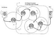
- FIG. 6Another embodiment of a distribution network is shown in FIG. 6 .
- the OPP devicesthemselves function as relaying nodes and form what is referred to as a mesh network.
- the OPPscan communicate using TCP/IP high layer protocols typically using an 802.15.4 based wireless protocol, which is designed to convey TCP/IP.
- an end device 2is communicating with the ultimate destination, the host 6 .
- the grouping of intermediate OPPsfunction as network routing and relaying devices is known as a ‘mesh network’ 20 .
- the OPPs in the mesh network 20function as network nodes or routers in this application, not as OPPs 4 a communicating with an end device.
- OPP 4 afunctions as an OPP communicating with an end device.
- the mesh networkcomprises a plurality of OPPs 4 b - 4 e communicating with each other through a series of limited distance hops in order to reach the host. This architecture is known to those familiar with IEEE 802.15.4.
- the end device 2is within the transmission range of an OPP 4 a .
- the transmission rangeis illustrated for the OPP 4 a using a circle 5 . This represents the range of the OPP for a given transmitter power level.
- an end-deviceis transmitting within the range 5 of the OPP 4 a , then the end device will be able to communicate with the OPP, and vice versa.
- the end deviceis illustrated as just within the range 5 of the OPP 4 a .
- OPP 4 ais able to communicate to OPP 4 b since they are within communication range of each other, which in turn is able to communicate to OPP 4 c , then to another OPP 4 d , then to another OPP 4 e , then in turn, finally to the host 6 .
- the mesh networkcan be modeled in a number of ways from a protocol layering perspective.
- the mesh network 20may function in the aggregate as the single OPP comprising the protocol stack 302 a , 302 b of FIG. 4 c in which application information is transparently passed between the end device and host.
- the mesh network 20may function in the aggregate as the single OPP comprising the protocol stack 302 a , 302 b of FIG. 4 d where the application level messages are processed.
- a select number of OPPs 4 b - 4 emay serve as a network to OPP 4 a .
- OPP 4 acommunicates directly to the host using the other OPPs as a network service provider (e.g., a subnet of the Internet).
- This schemerequires less regulatory compliance compared to other forms of wireless transmission since the 802.-based suite of protocols operate in the unlicensed frequency band.
- FCC regulationsstill require transmission within certain power levels.
- the typical range of such unitsis flexible and depends on the power levels and transmission bandwidth. As the number of OPPs (known as routing nodes in 802.15.4) are deployed, the average distance to the nearest OPP decreases and the required power levels can be decreased.
- the TCP/IP protocolis used for addressing messages between the various elements.
- the 802based suite of protocolsuses TCP/IP and incorporates the well-known IP addressing scheme using MAC (media access control) addresses.
- MAC addressesuniquely identify a node on a LAN
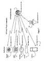
- FIG. 7illustrates how various types of end devices can communicate with the OPP.
- each of the end devicesis assigned a MAC address. This address can be programmed into the device at manufacturer, or dynamically assigned.
- the end devicesrepresent typical control devices communicating with the OPP, including a thermostat control 2 , an alarm system 30 , a water meter 32 , a cable set top box 34 , an appliance 36 , and a gas meter 100 .
- Each end devicecommunicates using a wireless 802 based protocol to the OPP 4 , which is illustrated as co-located with the power meter.
- the power meteris usually affixed to the exterior of a residence or commercial building, and the end devices are typically within the range of the OPP 4 located at the same premise. Typically, the distance between the end device and OPP less than 100 feet. Because it is possible that there may be several OPPs co-located into power meters within the range of transmission of the end-device and OPP, a scheme for registering the end-device is required.
- each end-devicecould be locally programmed to enter the address of the OPP. Such mechanisms are indicated in 802 standards specifications.
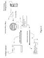
- FIG. 8summarizes several of the inventive aspects of the aforementioned discussion in light of an energy management application.
- an end device 2recognizes the presence of a nearby OPP 4 functioning as a relay of information allowing the energy management application in the end device have peer-to-peer communication 56 with the energy management application in the host 6 .
- the OPP 4relays information using a distribution network, which can be any of the aforementioned distribution networks, including an 802.15.4 mesh network 20 based on a network of OPPs.
- the mesh network 20has connectivity with the host 6 via a connection 54 . It is possible that the ‘last’ OPP in the mesh network is actually hardwired via a connection 54 to the host via a wireline communication facility (e.g., T1 connection).
- a wireline communication facilitye.g., T1 connection
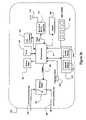
- the energy management host computer 6is further defined in FIG. 9 .
- the energy management hostcomprises various processing related components.
- the processing system 72is typically a large-scale server capable of processing simultaneous communication with numerous remote end devices.
- An operator console 73allows administration of the various end-device accounts, including creating, editing, and deleting accounts, and other operational related functions.
- Various system status indicatorscan be provided on the operator console 73 as well as the printer 74 .
- the printeris typically used to print out period reports.
- the processing system 72also accesses memory 76 used to store various data and application programs.
- the main energy management applicationincluding a meter reading application 77 a , data pertaining to when each meter is read (typically based on the customer's billing cycle) 77 b , the report generator application which takes the meter reading data and aggregates it into the desired form 77 c , an account management application 77 d allowing new accounts to be established or edited, and an alarm generator 77 e used to indicate an abnormal status.
- the main energy management applicationincluding a meter reading application 77 a , data pertaining to when each meter is read (typically based on the customer'
- the processing system 72is also connected to a communication interface 71 , which in turn connects to the distribution network 54 . Since a variety of distribution network technologies may be used, the communication interface 71 allows the remainder of the host processing system, namely processing system 72 , to be independent of the particular distribution network used.
- the processing system 72also accesses a database 75 for storing meter-reading data.
- meter-reading dataare stored on a historical and present basis. Historical data may be stored in a separate database with slower performance requirements. Present data is typically accessible on a real time basis, since information of current usage is typically compared with recent past usage in previous years. Thus, the storage and reliability requirements may be different.
- FIG. 10A typical record format 80 stored in the database 75 is illustrated in FIG. 10 .
- a meter identification number in the column header 81is used to identify a particular meter's data.
- four separate meters 84 a - 84 dare shown, though typically data for thousands of meters are stored.
- the meter numbersare determined by the energy service provider or meter manufacturer, and may not necessarily identify the customer's account.
- the next column 82identifies the customer account's rate plan, which indicates how bills are calculated based on usage. Typically, additional rating plan data is accessed based on the plan identifier.
- a MAC address 83indicates the necessary address used to communicate with the particular meter. It is possible that other address schemes could be used.
- the next column 84indicates the activation status and date for that meter.
- the hostrecords the status as to whether a meter is active or inactive. For example, a meter may be ‘shut off’ to disconnect power when a residence is vacated. In this case, the meter would be labeled as ‘inactive’ and the date (and possibly time) of the event could be recorded.
- meter identification number 2350-529345 81 cis indicated as inactive as of 6/3/03 (Jun. 3, 2003) 84 c.
- the next meter account 84 dis indicated active as of 7/11/01 (Jul. 11, 2001).
- the hostmay maintain in each record a load restriction status 87 .
- This fieldindicates whether the customer is participating in a load reduction program. Specifically, if ‘allowed’, the customer is willing to receive and act upon a load reduction request in exchange, potentially, for a favorable billing rate.
- one accounthas indicated 87 d participation in load reduction. Further, the indication is listing as ‘pending’ 87 d indicating that load reduction procedures are currently active for that account.
- the hostmay maintain information regarding typical load reduction amounts for each customer, and use that is determining an aggregate running load reduction when a load reduction initiative is pending. Thus, a host may issue load reduction requests until a threshold of aggregate load reduction level have been met, at which point the host may not longer issue such requests.
- the hostmay prioritize certain customers based on load size or other factors.
- the hostmay maintain records (e.g., another column indicating) for each customer participating in the load reduction program if the customer was sent a request and subsequently rejected by the customer. In other words, the customer received the request to reduce their load and chose not to reduce their load. The host may ‘flag’ such customers for not participating in load reduction so that any predefined economic penalties can be calculated.
- each meterincludes various meter-reading data.
- column 85indicates the first reading
- the next column 86indicates the next meter reading, and so on.
- a finite time period of datais retained (e.g., the 12-24 months) in the present database.
- the meter of row 81 dhas an initial reading of 34.5 units measured at 12:48 p.m. on Jun. 3, 2003 85 d .
- the meter reading datatypically includes the current reading and the time and date the reading occurred. Other variations on the data structure are possible.
- meter reading datacan refer to any type of data collected from a meter, and is not limited to only usage data, but can refer to status, time, and any other type of data measurements retained in the meter, including power quality aspects, low voltage indications, frequency variations, etc. Those skilled in the art will recognize a variety of parameters that can be read, stored, and transmitted to a host.
- One such applicationis the limiting of power consumption by major power loads.
- the power utility companiesmaintain a list of large power consumption users. If power consumption within a region reaches a threshold, the power utility will typically telephone these customers and request that they voluntarily lower their power consumption. This typically occurs by the customer voluntarily turning off loads, such as air conditioning systems, for a limited time.
- Power companiesmay offer reduced rates to customers if customers voluntarily reduce their consumption when requested.
- the procedures for reducing power consumptionis largely a manual process, and automated procedures using the aforementioned architecture would facilitate such situations.
- a host system 6manages the power system demand.
- the host 6receives various real-time inputs (not shown) of current power consumption in various serving areas associated with the power grid.
- the hostalso employs an energy management application determining when a load threshold has been reached, warranting the indication of an alarm requiring the voluntary reduction in power from various customer loads.
- the hosttypically maintains a database of all the customer energy loads, including their load characteristics, their relationship to the power distribution grid, and associated contact related information.
- the hostinitially identifies customer loads for energy management.
- power loadsmay represent critical applications where power cannot be reduced (e.g., hospitals, emergency responders, etc.) and are not suitable for energy management.
- the host 6issues a ‘power demand status’ indicator 93 that is communicated to a target OPP 4 .
- the communicationmay occur using a variety of the distribution networks identified, such as the aforementioned paging network, and using either standard or proprietary signaling.
- the messageis sent from the host to the OPP and terminated at the OPP.
- the message 93may include a time duration indicating a default duration or requested time duration (e.g., four hours) that the power restriction procedures are in place.
- the OPPhas a timer so that the appropriate amount of time can be determined.
- a follow up message terminating the power restrictionscan be issued by the host.
- the recording of the status indication as well as each customer's responsecan be incorporated into each embodiment, but is only illustrated in this embodiment for brevity.
- the OPPis integrated into the power meter and is able to control the flow of power as required in various applications.
- the ‘power demand status’indicates the presence of a ‘high power demand’ condition. This is triggered when power demand is, or is projected to, exceed a pre-set threshold. The receipt of this message by the OPP in this embodiment does not result in termination of power by the power meter. Rather, the OPP simply records this status in order to respond to a request from a load controller for permission to activate a load. Similarly, the host can reset the power demand status (indicating the absence of a ‘high power demand’ condition) by sending a subsequent message altering the status indicated.
- the ‘power load’ in FIG. 11is represented by the intelligent thermostat control 2 .
- the intelligent thermostat 2is the controller of an air conditioning system, and the actual load is the motor running the compressor in the A/C unit. However, since the intelligent thermostat controller activates the A/C unit, the controller is used to represent the power load.
- the intelligent thermostat 2Whenever the intelligent thermostat 2 determines that load activation is appropriate, it will first initiate a “request message” 90 to the OPP requesting authorization to turn on. Since the intelligent thermostat does not know the power demand status, it must first check with the OPP.
- the OPP 4receives the request and reads the current power demand status indication that it previously received from the host, which is stored in non-volatile memory.
- the OPPprocesses the request 91 and responds to the controller with a “response message” 92 .
- the “response message”may indicate authorization or denial to activate the load.
- This energy management communication architecturesupports two different energy management schemes.
- the OPPhas absolute control over whether the intelligent thermostat can activate its load or not.
- the “response message”directly controls the operation of the end device. In some scenarios, this type of energy management may be desirable. However, there are numerous applications in which the customer would like to chose whether they would voluntarily comply with the request to lower power consumption or not.
- the ‘response message’ indicating authorization or denial to activate a loadis only an advisory indication from the OPP.
- the intelligent thermostatafter becoming aware of the status, then determines on its own whether to activate the load or not. This allows the customer to have final control over any voluntary reduction of load consumption.
- the architecture presented in FIG. 11is characterized by: information being transferred between the host and the OPP, the OPP processing and storing the information, and the OPP subsequently interacting with the end device.
- the architecturealso presumes that the intelligent thermostat will query the OPP prior to each activation. This may result in unnecessary requests communicated to the OPP, particularly during a time when there are no power restrictions (e.g., during the winter time).
- additional messagesmay be defined to improve the messaging efficiency. For example, many power load problems occur in the summer months when A/C usage is at a peak.
- a host processorcan often predict when power load restrictions are required (e.g., comparing recent usage and forecasted temperatures).
- the power system hostcan issue a command to the OPP requesting the OPP to indicate to the end-devices that the end devices should request authorization before activation until notified otherwise. In this manner, a host can predict for a given day the possibility of restrictions and notify the OPPs to notify the end devices that load activation requests should occur. This allows ‘deactivating’ the energy management system as needed (e.g., during winter) and ‘reactivating’ the system when required (e.g., during summer).
- Another variation of the previous control architectureinvolves the end device querying the OPP prior to load activation, but the OPP defaults to authorizing activation unless a power restriction indication has been received from the host. If a power restriction indication was received, the OPP will initiate a query to the host indicating the particular end device that is requesting load activation. The host response is received and relayed by the OPP to the end device. In this manner, the host is not burdened with handling load activation request until the host first notifies the OPP. However, the OPP is burdened with processing messages from the end device. Similarly, once conditions warrant, the host can indicate the absence of a power restriction to the OPP, where after the OPP defaults to approving load requests from the end device.
- FIG. 12embodies another variation of managing power consumption in a power load.
- the intelligent thermostat 2again initiates a ‘request message’ 90 to the OPP.
- the OPP 4recognizes the request message requires determination of the power demand status, and in response generates a query to the host 6 .
- the query messageis a “request message” 95 requesting the current power demand status.
- the hostreceives the message, and based on determination of the power demand status, the host responds with a ‘response message’ 96 that is sent to the OPP.
- the OPPrecognizing that a pending response the end device is required, generates a ‘response message’ 92 with the appropriate authorization or denial.
- the OPP in FIG. 11processes requests from the end device autonomously
- the OPP in FIG. 12processes each request from the end device by relaying a corresponding message to the host.
- the OPPterminates messages from the end device, and initiates a separate message to the host.
- the OPPis largely unaware of the energy management application. Specifically, the OPP functions to relay a message received from an end device in one protocol by mapping it to another protocol sent to the host.
- the OPPmay, in some implementations, convert the messages from the end device from one physical protocol (e.g., 802.15.4) to another protocol (e.g., 802.11X or a wireline based protocol), based on the type of distribution network protocol used between the OPP and the host.
- one physical protocole.g., 802.15.4
- another protocole.g., 802.11X or a wireline based protocol
- the request message 90is generated by the intelligent thermostat 2 to the OPP 4 .
- the OPPis only required to map the message to a predetermined address associated with the host 6 .
- the request message from the end device 90is mapped to a request message 97 to the host.
- the OPPmay or may not be aware of the meaning of the messages, namely that the message is a request to activate the power load.
- the host 6does interpret and process the message, and returns a response message 98 that is received by the OPP 4 , which in turn maps the contents to a message 92 and transmits it to the end device.
- FIG. 13also allows illustration of another concept that can apply to other embodiments. Namely, after the host 6 responds with the response message 98 , the host may record the load restriction status (column 87 of FIG. 10 ) in a data structure associated with the customer. This allows the host to maintain current indications of whether a load restriction request is pending for a given customer. The host may estimate the load ‘savings’ for each account and maintain a summary of the total load ‘savings’ for all customers with a pending load restriction. Alternatively, the host may then on an interim basis frequently read usage data from those customers to determine in real time the load reduction that has occurred from initiating a series of load reduction indications. In this manner, the host using the data structure and potentially in combination with the other meter reading capabilities, may be able to obtain feedback regarding the effects of a load reduction initiative.
- the host systemcan also provide data to the OPP that is used by the OPP to process requests subsequently received by the OPP for yet another variation of energy management.
- an ‘intelligent’ appliancemay obtain power rate information prior to activating itself. Such rate information could include times when ‘off-peak’ and ‘peak’ billing rates occur.
- an appliance or power loadmay initiate a query for information regarding current power rates and use such information in determining whether to activate the power load. Many appliances, such as A/C units, refrigerators, and dishwashers may be able to defer activation for a short time period if power rates are reduced in the near future. This is embodied in FIG. 14 . In FIG.
- a power system management host 6sends a notification message 120 conveying power rate data.
- This datatypically includes a time schedule indicating the absolute or relative rate data for power consumption. For example, ‘off peak’ power rates could be indicated as occurring from 10:00 p.m. to 6:00 a.m.
- the host 6periodically provides this information to the OPP 4 that stores the rate data in its memory. This could be done on a daily basis reflecting anticipated power demand.
- the intelligent appliance 126 illustrated here as a dishwasherinitiates a query 122 requesting information regarding the rate status.
- the communicationtypically occurs using one of the 802-based suite of wireless protocols.
- the OPP 4 receiving the messageperforms internal processing 121 to retrieve the rate information stored.
- the OPP 4then generates a response message 124 containing the rate data.
- the OPPmay provide a subset of the rate data in the response, e.g. only that data of the schedule pertaining to future times.
- the intelligent appliance 126processes the rate data 125 to determine whether it should self activate or defer self activation until an ‘off-peak’ rate occurs.
- information from the power system management host 6can be disseminated to a plurality of OPPs, which in turn disseminates the information to an end device allowing the end device to determine whether it should activate or defer activation of a power load.
- Another variation of the end device obtaining rate informationis possible in which the end device sends a query for rate information to the OPP, and the OPP relays the request to the host. The host responds to the OPP and in turn, the OPP relays the response to the end device.
- This message flowwould be analogous to the message flow of FIG. 12 where the OPP functions to rely information between the end device and host.
- the aforementioned systemis not limited to energy management for load activation, but can also be used to read data from an electrical meter, or other types of meters.
- FIG. 15involving reading values from a gas utility meter.
- the host 6is a meter reading management system that issues a command 110 to the OPP 4 directing the OPP to read information from the indicated meter.
- the meteris identified by a particular address, such as the aforementioned MAC addresses.
- the OPP 4receives the request and determines via an address table in memory if there is an established association with the indicated address.
- the OPP 4is in the nearby vicinity of the three utility meters as indicated by the dotted line 101 —the power meter (integrated with the OPP 4 ), the gas meter 100 , and the water meter 32 .
- the OPP 4may have established a table with addresses for each of the meters and knows it is able to communicate with each meter.
- the OPPtypically communicates using one of the 802-based suite of wireless protocols.
- reading datamay be accomplished using proprietary messaging protocol since the OPP is integrated with the power meter.
- the OPP and power metermay not be integrated and the OPP uses 802.11X-based protocols to communicate with the power meter.
- the OPP 4issues a query or command 112 to the target meter to read the current value.
- the gas meter 100returns a response message containing the meter reading data 114 , which is received and processed by the OPP 4 .
- the OPP 4conveys the information in a message 116 to the host. The host then records the data as required in the data structure containing the meter reading data.
- the OPPcould autonomously read the meter on a periodic basis (e.g., daily), and store the data in memory.
- the OPPupon receiving a command from the host could then transmit the plurality of data values to the host.
- the OPPmay terminate the message from the host and generate different application level messages to the end device (e.g., the gas meter).
- the OPPmay simply relay the message to the end device, as well as relay the response to the host.
- the OPPmay periodically collect data from the remote meter and autonomously send it to the host, or send the data upon request to the host.
- the data measured, stored, and transmittedmay be usage related data from the meter, but may comprise any other data retained in the meter, including status, time, and various power quality parameters, such as voltage dips/spikes, average/peak/low voltage frequencies, maximum current draw, et cetera.
- the embodiments illustrated and the phrase ‘meter reading’is not limited to applications only involving usage data.
- FIG. 16indicates another energy management application directed to emergency load control management.
- the host processormay require deactivation of a load, either in emergency or non-emergency circumstances. In this case, the host may have absolute control over the activation/deactivation of the power load.
- the host 6issues a message 130 of an impending load deactivation to the OPP 4 .
- This notification messageis intended to ‘warn’ the OPP that an impending power deactivation command should be expected.
- the OPP 4responds with an acknowledgement message 132 indicating whether it is able to comply with a future load deactivation or not. This acknowledgement serves at least two functions. First, it confirms receipt of the notification to the host.
- the hostis able to obtain an indication of whether the load can be deactivated.
- the power management host systemmay not maintain information about all the load applications under the control of the OPP.
- various life sustaining medical equipmentmay be operating as a load from the power meter and the acknowledgement of the OPP may indicate that it cannot comply with a load deactivation request. This may be used by the host to avoid sending a load deactivation request to the OPP.
- the hostmay issue a load deactivation notification 134 requesting immediate shut down of all loads.
- the OPPissues an acknowledgement message 135 indicating that the power load has been terminated. The host then records this information and may sequence through other OPPs to reduce additional loads until the necessary overload to the power grid is reduced.
- the above sequencecan be adapted to accomplish deactivation of a meter, typically for non-payment or normal termination of service.
- a similar ‘activation’ sequencecould be used to activate a meter for establishment of service. This would facilitate normal activation/termination of power service and avoid a service call to the location.
- the systemcould apply to any type of electrical controller, including solenoids, mechanical switches, or solid state relays or other electronic components.
- the power load activatedis not limited to motors in A/C units, but any type of motor in a device, including a pump, compressor, machine, drive unit, material handling system, etc.
- the controlleris not limited to controlling power loads, but may control the flow of liquids, gases, or solids through valves, manifolds, gates, or various types of material handling devices.
- the controllercan control industrial machines, processes, lighting, sensors, detectors, or other type of devices.
- the control mechanismcan control access to locations, authorization activation of security systems, or activation of an industrial process.
- the systemcan be used to activate/deactivate a device, such that the unit could be taken ‘off-line’ if necessary.
- the unitcan be remote activated once service is restored.
- the OPPcould be standalone or integrated into valves, machines, or any of the various types of controllers.
- the systemmay be used to read or write data from a particular device, such as reading meter data, including obtaining readings from water or gas utility meters.
- the information obtainedmay be usage data, status indications, or periodic usage or rate of use information.
- Information other than usage that may be obtained by a meter or devicecan be reported or read to/by the host computer, including water line or gas line pressure readings, line voltage, line voltage dips, voltage frequency, or any other measurable parameter.
Landscapes
- Engineering & Computer Science (AREA)
- Physics & Mathematics (AREA)
- General Physics & Mathematics (AREA)
- Computer Networks & Wireless Communication (AREA)
- Signal Processing (AREA)
- Health & Medical Sciences (AREA)
- Computing Systems (AREA)
- General Health & Medical Sciences (AREA)
- Medical Informatics (AREA)
- Power Engineering (AREA)
- Remote Monitoring And Control Of Power-Distribution Networks (AREA)
- Mobile Radio Communication Systems (AREA)
Abstract
Description
- 802.11—Wireless LAN Physical and MAC layer specification (2.4 GHz.),
- 802.11a—Wireless LAN Physical and MAC layer specification (5 Ghz),
- 802.11b—Higher speed (5.5 and 11 Mbps),
- 802.11c—Bridge Operations,
- 802.11d—Operation in additional regulatory domains,
- 802.11e—Quality of Service parameters,
- 802.11f—Multi-vendor access point interoperability Access Distribution Systems,
- 802.11g—Higher rate (20 Mbps) extensions in the 2.4 GHz band,
- 802.11h—Enhancements for Dynamic Channel Selection,
- 802.11i—Security and Authentication.
Thus, the 802.11 suite of protocols encompasses a variety of past and present protocols designed to inter-work together.
Claims (18)
Priority Applications (1)
| Application Number | Priority Date | Filing Date | Title |
|---|---|---|---|
| US10/729,532US7289887B2 (en) | 2003-09-08 | 2003-12-05 | Systems and methods for remote power management using IEEE 802 based wireless communication links |
Applications Claiming Priority (2)
| Application Number | Priority Date | Filing Date | Title |
|---|---|---|---|
| US10/658,493US20050055432A1 (en) | 2003-09-08 | 2003-09-08 | Systems and methods for remote power management using 802.11 wireless protocols |
| US10/729,532US7289887B2 (en) | 2003-09-08 | 2003-12-05 | Systems and methods for remote power management using IEEE 802 based wireless communication links |
Related Parent Applications (1)
| Application Number | Title | Priority Date | Filing Date |
|---|---|---|---|
| US10/658,493Continuation-In-PartUS20050055432A1 (en) | 2003-09-08 | 2003-09-08 | Systems and methods for remote power management using 802.11 wireless protocols |
Publications (2)
| Publication Number | Publication Date |
|---|---|
| US20050065742A1 US20050065742A1 (en) | 2005-03-24 |
| US7289887B2true US7289887B2 (en) | 2007-10-30 |
Family
ID=46301733
Family Applications (1)
| Application Number | Title | Priority Date | Filing Date |
|---|---|---|---|
| US10/729,532Expired - Fee RelatedUS7289887B2 (en) | 2003-09-08 | 2003-12-05 | Systems and methods for remote power management using IEEE 802 based wireless communication links |
Country Status (1)
| Country | Link |
|---|---|
| US (1) | US7289887B2 (en) |
Cited By (122)
| Publication number | Priority date | Publication date | Assignee | Title |
|---|---|---|---|---|
| US20050240314A1 (en)* | 2004-04-27 | 2005-10-27 | Martinez Edwin A | Method and apparatus for controlling and monitoring electrical power consumption |
| US20050268322A1 (en)* | 2004-05-04 | 2005-12-01 | Watson Scott F | Apparatus and method for utilizing a pre-existing power grid to provide internet access to a home or office or the like |
| US20060023853A1 (en)* | 2004-07-01 | 2006-02-02 | Christopher Shelley | Method of remote collection of data for the account of an entity, using a third party data communication network, e.g. for automatic meter reading |
| US20060049694A1 (en)* | 2004-09-03 | 2006-03-09 | Lawrence Kates | Method and apparatus for load management in an electric power system |
| US20070089163A1 (en)* | 2005-10-18 | 2007-04-19 | International Business Machines Corporation | System and method for controlling security of a remote network power device |
| US20070203860A1 (en)* | 2006-02-24 | 2007-08-30 | Gridpoint, Inc. | Energy budget manager |
| US20070239317A1 (en)* | 2006-04-07 | 2007-10-11 | Bogolea Bradley D | Artificial-Intelligence-Based Energy Auditing, Monitoring and Control |
| US20080281473A1 (en)* | 2007-05-08 | 2008-11-13 | Pitt Ronald L | Electric energy bill reduction in dynamic pricing environments |
| US20090012916A1 (en)* | 2007-07-07 | 2009-01-08 | Alexander Montgomery Barnett | Energy optimization system and method |
| US20090062970A1 (en)* | 2007-08-28 | 2009-03-05 | America Connect, Inc. | System and method for active power load management |
| US20090063228A1 (en)* | 2007-08-28 | 2009-03-05 | Forbes Jr Joseph W | Method and apparatus for providing a virtual electric utility |
| US20090088907A1 (en)* | 2007-10-01 | 2009-04-02 | Gridpoint, Inc. | Modular electrical grid interface device |
| US20090153356A1 (en)* | 2007-12-18 | 2009-06-18 | Elster Electricity Llc. | System and method for collecting information from utility meters |
| US20090160267A1 (en)* | 2006-06-26 | 2009-06-25 | Lawrence Kates | Method and apparatus for temperature-based load management metering in an electric power system |
| US20090160674A1 (en)* | 2007-12-20 | 2009-06-25 | Vangala Reddy R | Wi-Fi enabled telemetry |
| US20090211986A1 (en)* | 2008-02-22 | 2009-08-27 | Lawrence Kates | Method and apparatus for energy-efficient temperature-based systems management |
| US20100010683A1 (en)* | 2008-07-14 | 2010-01-14 | Lawrence Kates | Method and apparatus for power-limiting electrical access |
| US20100039263A1 (en)* | 2008-07-10 | 2010-02-18 | Christopher Way-Fung Chen | System and method for utilization of smart meter infrastructure |
| US20100110077A1 (en)* | 2008-11-06 | 2010-05-06 | Gary Grossman | System and method for identifying power usage issues |
| US20100145534A1 (en)* | 2007-08-28 | 2010-06-10 | Forbes Jr Joseph W | System and method for determining and utilizing customer energy profiles for load control for individual structures, devices, and aggregation of same |
| US20100145544A1 (en)* | 2007-08-28 | 2010-06-10 | Forbes Jr Joseph W | System and method for selective disconnection of electrical service to end customers |
| US20100191487A1 (en)* | 2009-01-26 | 2010-07-29 | Geneva Clean Tech Inc. | Energy usage monitoring with remote display and automatic detection of appliance including graphical user interface |
| US20100222935A1 (en)* | 2007-08-28 | 2010-09-02 | Forbes Jr Joseph W | System and method for estimating and providing dispatchable operating reserve energy capacity through use of active load management |
| US20110014959A1 (en)* | 2009-07-17 | 2011-01-20 | Qualcomm Incorporated | Antenna Array Isolation For A Multiple Channel Communication System |
| US20110106316A1 (en)* | 2011-01-12 | 2011-05-05 | David Scott Drew | Apparatus and method for determining load of energy consuming appliances within a premises |
| US20120029714A1 (en)* | 2011-01-18 | 2012-02-02 | General Electric Company | Heg - single primary network to multiple secondary network energy management |
| US8138934B2 (en) | 2007-11-25 | 2012-03-20 | Trilliant Networks, Inc. | System and method for false alert filtering of event messages within a network |
| US8145361B2 (en) | 2007-08-28 | 2012-03-27 | Consert, Inc. | System and method for manipulating controlled energy using devices to manage customer bills |
| US8144596B2 (en) | 2007-11-25 | 2012-03-27 | Trilliant Networks, Inc. | Communication and message route optimization and messaging in a mesh network |
| US8171364B2 (en) | 2007-11-25 | 2012-05-01 | Trilliant Networks, Inc. | System and method for power outage and restoration notification in an advanced metering infrastructure network |
| US20120159641A1 (en)* | 2010-12-21 | 2012-06-21 | Sergio Rossi | Power Meter Arrangement |
| US20120197455A1 (en)* | 2011-01-31 | 2012-08-02 | Samsung Electronics Co., Ltd. | Method and apparatus for managing power of smart appliance |
| US20120246042A1 (en)* | 2011-03-21 | 2012-09-27 | Nathan Bowman Littrell | Systems and methods for generating a utility bill |
| US8289182B2 (en) | 2008-11-21 | 2012-10-16 | Trilliant Networks, Inc. | Methods and systems for virtual energy management display |
| US8319658B2 (en) | 2009-03-11 | 2012-11-27 | Trilliant Networks, Inc. | Process, device and system for mapping transformers to meters and locating non-technical line losses |
| US8332055B2 (en) | 2007-11-25 | 2012-12-11 | Trilliant Networks, Inc. | Energy use control system and method |
| US20120316689A1 (en)* | 2011-06-08 | 2012-12-13 | Alstom Grid | Enhanced communication infrastructure for hierarchical intelligent power distribution grid |
| US8334787B2 (en) | 2007-10-25 | 2012-12-18 | Trilliant Networks, Inc. | Gas meter having ultra-sensitive magnetic material retrofitted onto meter dial and method for performing meter retrofit |
| USD672666S1 (en) | 2011-01-12 | 2012-12-18 | Emerson Electric Co. | Thermostat |
| US8478447B2 (en) | 2010-11-19 | 2013-07-02 | Nest Labs, Inc. | Computational load distribution in a climate control system having plural sensing microsystems |
| US8502640B2 (en) | 2007-11-25 | 2013-08-06 | Trilliant Networks, Inc. | System and method for transmitting and receiving information on a neighborhood area network |
| US8527107B2 (en) | 2007-08-28 | 2013-09-03 | Consert Inc. | Method and apparatus for effecting controlled restart of electrical servcie with a utility service area |
| US8539567B1 (en) | 2012-09-22 | 2013-09-17 | Nest Labs, Inc. | Multi-tiered authentication methods for facilitating communications amongst smart home devices and cloud-based servers |
| US8542685B2 (en) | 2007-08-28 | 2013-09-24 | Consert, Inc. | System and method for priority delivery of load management messages on IP-based networks |
| US8594850B1 (en) | 2012-09-30 | 2013-11-26 | Nest Labs, Inc. | Updating control software on a network-connected HVAC controller |
| US8620841B1 (en) | 2012-08-31 | 2013-12-31 | Nest Labs, Inc. | Dynamic distributed-sensor thermostat network for forecasting external events |
| US8627127B2 (en) | 2011-02-24 | 2014-01-07 | Nest Labs, Inc. | Power-preserving communications architecture with long-polling persistent cloud channel for wireless network-connected thermostat |
| US8630741B1 (en) | 2012-09-30 | 2014-01-14 | Nest Labs, Inc. | Automated presence detection and presence-related control within an intelligent controller |
| US8635373B1 (en) | 2012-09-22 | 2014-01-21 | Nest Labs, Inc. | Subscription-Notification mechanisms for synchronization of distributed states |
| US8700187B2 (en) | 2007-08-28 | 2014-04-15 | Consert Inc. | Method and apparatus for actively managing consumption of electric power supplied by one or more electric utilities |
| US8699377B2 (en) | 2008-09-04 | 2014-04-15 | Trilliant Networks, Inc. | System and method for implementing mesh network communications using a mesh network protocol |
| US8695888B2 (en) | 2004-10-06 | 2014-04-15 | Nest Labs, Inc. | Electronically-controlled register vent for zone heating and cooling |
| US8781462B2 (en) | 2009-09-28 | 2014-07-15 | Itron, Inc. | Methodology and apparatus for validating network coverage |
| US8806239B2 (en) | 2007-08-28 | 2014-08-12 | Causam Energy, Inc. | System, method, and apparatus for actively managing consumption of electric power supplied by one or more electric power grid operators |
| US8805552B2 (en) | 2007-08-28 | 2014-08-12 | Causam Energy, Inc. | Method and apparatus for actively managing consumption of electric power over an electric power grid |
| US8832428B2 (en) | 2010-11-15 | 2014-09-09 | Trilliant Holdings Inc. | System and method for securely communicating across multiple networks using a single radio |
| US8838282B1 (en) | 2009-11-16 | 2014-09-16 | Comverge, Inc. | Method and system for providing a central controller that can communicate across heterogenous networks for reaching various energy load control devices |
| US20140267296A1 (en)* | 2013-03-15 | 2014-09-18 | Fluke Corporation | Automated Combined Display of Measurement Data |
| US8843239B2 (en) | 2010-11-19 | 2014-09-23 | Nest Labs, Inc. | Methods, systems, and related architectures for managing network connected thermostats |
| US8849715B2 (en) | 2012-10-24 | 2014-09-30 | Causam Energy, Inc. | System, method, and apparatus for settlement for participation in an electric power grid |
| US8855279B2 (en) | 2007-08-28 | 2014-10-07 | Consert Inc. | Apparatus and method for controlling communications to and from utility service points |
| US8856323B2 (en) | 2011-02-10 | 2014-10-07 | Trilliant Holdings, Inc. | Device and method for facilitating secure communications over a cellular network |
| US8891338B2 (en) | 2009-01-29 | 2014-11-18 | Itron, Inc. | Measuring the accuracy of an endpoint clock from a remote device |
| US8890505B2 (en) | 2007-08-28 | 2014-11-18 | Causam Energy, Inc. | System and method for estimating and providing dispatchable operating reserve energy capacity through use of active load management |
| US8924033B2 (en) | 2010-05-12 | 2014-12-30 | Alstom Grid Inc. | Generalized grid security framework |
| US8923339B2 (en) | 2011-03-06 | 2014-12-30 | PCN Technology, Inc. | Systems and methods of data transmission and management |
| US8930038B2 (en) | 2012-07-31 | 2015-01-06 | Causam Energy, Inc. | System, method, and apparatus for electric power grid and network management of grid elements |
| US8965590B2 (en) | 2011-06-08 | 2015-02-24 | Alstom Grid Inc. | Intelligent electrical distribution grid control system data |
| US8970394B2 (en) | 2011-01-25 | 2015-03-03 | Trilliant Holdings Inc. | Aggregated real-time power outages/restoration reporting (RTPOR) in a secure mesh network |
| US8983669B2 (en) | 2012-07-31 | 2015-03-17 | Causam Energy, Inc. | System, method, and data packets for messaging for electric power grid elements over a secure internet protocol network |
| US8996183B2 (en) | 2007-08-28 | 2015-03-31 | Consert Inc. | System and method for estimating and providing dispatchable operating reserve energy capacity through use of active load management |
| US8998102B2 (en) | 2011-10-21 | 2015-04-07 | Google Inc. | Round thermostat with flanged rotatable user input member and wall-facing optical sensor that senses rotation |
| US9001787B1 (en) | 2011-09-20 | 2015-04-07 | Trilliant Networks Inc. | System and method for implementing handover of a hybrid communications module |
| US9013173B2 (en) | 2010-09-13 | 2015-04-21 | Trilliant Networks, Inc. | Process for detecting energy theft |
| US9026232B2 (en) | 2010-11-19 | 2015-05-05 | Google Inc. | Thermostat user interface |
| US9041349B2 (en) | 2011-03-08 | 2015-05-26 | Trilliant Networks, Inc. | System and method for managing load distribution across a power grid |
| US9084120B2 (en) | 2010-08-27 | 2015-07-14 | Trilliant Networks Inc. | System and method for interference free operation of co-located transceivers |
| US9091453B2 (en) | 2012-03-29 | 2015-07-28 | Google Inc. | Enclosure cooling using early compressor turn-off with extended fan operation |
| US9098096B2 (en) | 2012-04-05 | 2015-08-04 | Google Inc. | Continuous intelligent-control-system update using information requests directed to user devices |
| US9130402B2 (en) | 2007-08-28 | 2015-09-08 | Causam Energy, Inc. | System and method for generating and providing dispatchable operating reserve energy capacity through use of active load management |
| US9175871B2 (en) | 2011-10-07 | 2015-11-03 | Google Inc. | Thermostat user interface |
| US9177323B2 (en) | 2007-08-28 | 2015-11-03 | Causam Energy, Inc. | Systems and methods for determining and utilizing customer energy profiles for load control for individual structures, devices, and aggregation of same |
| US9207698B2 (en) | 2012-06-20 | 2015-12-08 | Causam Energy, Inc. | Method and apparatus for actively managing electric power over an electric power grid |
| US9208676B2 (en) | 2013-03-14 | 2015-12-08 | Google Inc. | Devices, methods, and associated information processing for security in a smart-sensored home |
| US9268344B2 (en) | 2010-11-19 | 2016-02-23 | Google Inc. | Installation of thermostat powered by rechargeable battery |
| US9282383B2 (en) | 2011-01-14 | 2016-03-08 | Trilliant Incorporated | Process, device and system for volt/VAR optimization |
| US9281689B2 (en) | 2011-06-08 | 2016-03-08 | General Electric Technology Gmbh | Load phase balancing at multiple tiers of a multi-tier hierarchical intelligent power distribution grid |
| US9298196B2 (en) | 2010-11-19 | 2016-03-29 | Google Inc. | Energy efficiency promoting schedule learning algorithms for intelligent thermostat |
| US9359712B2 (en) | 2012-04-04 | 2016-06-07 | Whirlpool Corporation | Apparatus and method for controlling the energy usage of an appliance |
| US9400193B2 (en) | 2004-03-26 | 2016-07-26 | Aclara Technologies, Llc | Device, and associated method, for communication |
| US9429974B2 (en) | 2012-07-14 | 2016-08-30 | Causam Energy, Inc. | Method and apparatus for actively managing electric power supply for an electric power grid |
| US9453655B2 (en) | 2011-10-07 | 2016-09-27 | Google Inc. | Methods and graphical user interfaces for reporting performance information for an HVAC system controlled by a self-programming network-connected thermostat |
| US9461471B2 (en) | 2012-06-20 | 2016-10-04 | Causam Energy, Inc | System and methods for actively managing electric power over an electric power grid and providing revenue grade date usable for settlement |
| US9459018B2 (en) | 2010-11-19 | 2016-10-04 | Google Inc. | Systems and methods for energy-efficient control of an energy-consuming system |
| US9465398B2 (en) | 2012-06-20 | 2016-10-11 | Causam Energy, Inc. | System and methods for actively managing electric power over an electric power grid |
| US9595070B2 (en) | 2013-03-15 | 2017-03-14 | Google Inc. | Systems, apparatus and methods for managing demand-response programs and events |
| US9766270B2 (en) | 2013-12-30 | 2017-09-19 | Fluke Corporation | Wireless test measurement |
| US9807099B2 (en) | 2013-03-15 | 2017-10-31 | Google Inc. | Utility portals for managing demand-response events |
| US9810590B2 (en) | 2010-09-14 | 2017-11-07 | Google Inc. | System and method for integrating sensors in thermostats |
| US9810442B2 (en) | 2013-03-15 | 2017-11-07 | Google Inc. | Controlling an HVAC system in association with a demand-response event with an intelligent network-connected thermostat |
| US9890970B2 (en) | 2012-03-29 | 2018-02-13 | Google Inc. | Processing and reporting usage information for an HVAC system controlled by a network-connected thermostat |
| US9911095B2 (en) | 2015-04-06 | 2018-03-06 | Tank Utility | Monitoring and reporting a liquid level of a commodity in a tank |
| US9952573B2 (en) | 2010-11-19 | 2018-04-24 | Google Llc | Systems and methods for a graphical user interface of a controller for an energy-consuming system having spatially related discrete display elements |
| US10078319B2 (en) | 2010-11-19 | 2018-09-18 | Google Llc | HVAC schedule establishment in an intelligent, network-connected thermostat |
| US10095659B2 (en) | 2012-08-03 | 2018-10-09 | Fluke Corporation | Handheld devices, systems, and methods for measuring parameters |
| US10116560B2 (en) | 2014-10-20 | 2018-10-30 | Causam Energy, Inc. | Systems, methods, and apparatus for communicating messages of distributed private networks over multiple public communication networks |
| US10148761B2 (en) | 2015-04-09 | 2018-12-04 | Web Sensing, Llc | System-on-chip data security appliance and methods of operating the same |
| US10145577B2 (en) | 2012-03-29 | 2018-12-04 | Google Llc | User interfaces for HVAC schedule display and modification on smartphone or other space-limited touchscreen device |
| US10209751B2 (en) | 2012-02-14 | 2019-02-19 | Emerson Electric Co. | Relay switch control and related methods |
| US10295969B2 (en) | 2007-08-28 | 2019-05-21 | Causam Energy, Inc. | System and method for generating and providing dispatchable operating reserve energy capacity through use of active load management |
| US10346275B2 (en) | 2010-11-19 | 2019-07-09 | Google Llc | Attributing causation for energy usage and setpoint changes with a network-connected thermostat |
| US10443879B2 (en) | 2010-12-31 | 2019-10-15 | Google Llc | HVAC control system encouraging energy efficient user behaviors in plural interactive contexts |
| US10452083B2 (en) | 2010-11-19 | 2019-10-22 | Google Llc | Power management in single circuit HVAC systems and in multiple circuit HVAC systems |
| US10684633B2 (en) | 2011-02-24 | 2020-06-16 | Google Llc | Smart thermostat with active power stealing an processor isolation from switching elements |
| US10747242B2 (en) | 2010-11-19 | 2020-08-18 | Google Llc | Thermostat user interface |
| US10771868B2 (en) | 2010-09-14 | 2020-09-08 | Google Llc | Occupancy pattern detection, estimation and prediction |
| US10861112B2 (en) | 2012-07-31 | 2020-12-08 | Causam Energy, Inc. | Systems and methods for advanced energy settlements, network-based messaging, and applications supporting the same on a blockchain platform |
| US10938913B2 (en) | 2015-04-09 | 2021-03-02 | Web Sensing, Llc | Hardware turnstile |
| US11004160B2 (en) | 2015-09-23 | 2021-05-11 | Causam Enterprises, Inc. | Systems and methods for advanced energy network |
| US11133698B2 (en) | 2019-09-01 | 2021-09-28 | Wen Cai | Wireless charging systems and methods for controlling the same |
| US11334034B2 (en) | 2010-11-19 | 2022-05-17 | Google Llc | Energy efficiency promoting schedule learning algorithms for intelligent thermostat |
| US12438368B2 (en) | 2007-08-28 | 2025-10-07 | Causam Enterprises, Inc. | System and method for estimating and providing dispatchable operating reserve energy capacity through use of active load management |
Families Citing this family (48)
| Publication number | Priority date | Publication date | Assignee | Title |
|---|---|---|---|---|
| US6924538B2 (en) | 2001-07-25 | 2005-08-02 | Nantero, Inc. | Devices having vertically-disposed nanofabric articles and methods of making the same |
| US7089089B2 (en)* | 2003-03-31 | 2006-08-08 | Power Measurement Ltd. | Methods and apparatus for retrieving energy readings from an energy monitoring device |
| US7379791B2 (en)* | 2004-08-03 | 2008-05-27 | Uscl Corporation | Integrated metrology systems and information and control apparatus for interaction with integrated metrology systems |
| US8026830B2 (en)* | 2004-09-02 | 2011-09-27 | Boh Technology, L.L.C. | Methods and systems for meter reading and high speed data transfer |
| US7636340B2 (en)* | 2004-09-24 | 2009-12-22 | Simple Works, Inc. | System and method for communicating over an 802.15.4 network |
| US8976767B2 (en) | 2004-09-24 | 2015-03-10 | Simple Works, Inc. | System and method for communicating over an 802.15.4 network |
| US20060222006A1 (en)* | 2005-04-01 | 2006-10-05 | Valery Vinarov | Wireline to wireless converter |
| US8515348B2 (en)* | 2005-10-28 | 2013-08-20 | Electro Industries/Gauge Tech | Bluetooth-enable intelligent electronic device |
| US7741976B2 (en) | 2005-12-16 | 2010-06-22 | Hunt Power, L.P. | Server and method for processing meter data into a common format |
| US7688220B2 (en) | 2005-12-16 | 2010-03-30 | Hunt Power, L.P. | Device and method for processing meter data from multiple meters |
| US20070209057A1 (en)* | 2006-03-01 | 2007-09-06 | Broadband Wizard Inc. | Wireless delivery of broadband cable signals |
| US7779099B2 (en) | 2006-03-16 | 2010-08-17 | Us Beverage Net Inc. | Distributed intelligent systems and methods therefor |
| US7885917B2 (en)* | 2006-05-26 | 2011-02-08 | Board Of Regents Of The Nevada System Of Higher Education, On Behalf Of The Desert Research Institute | Utility monitoring and disaggregation systems and methods of use |
| US20130090744A1 (en)* | 2006-06-12 | 2013-04-11 | Bao Tran | Mesh network access controller |
| MX2009002249A (en)* | 2006-08-31 | 2009-03-16 | Itron Inc | Orchestration manager. |
| US20080074285A1 (en)* | 2006-08-31 | 2008-03-27 | Guthrie Kevin D | Interface between meter and application (IMA) |
| US8312103B2 (en)* | 2006-08-31 | 2012-11-13 | Itron, Inc. | Periodic balanced communication node and server assignment |
| US20080071930A1 (en)* | 2006-09-01 | 2008-03-20 | Holbrook Kenneth J | Native network transport |
| AU2012230096B2 (en)* | 2007-08-28 | 2016-02-11 | Landis+Gyr Technology, Inc. | Method and apparatus for providing a virtual electric utility |
| US20100235008A1 (en)* | 2007-08-28 | 2010-09-16 | Forbes Jr Joseph W | System and method for determining carbon credits utilizing two-way devices that report power usage data |
| WO2009067260A1 (en)* | 2007-11-25 | 2009-05-28 | Trilliant Networks, Inc. | Power-conserving network device for advanced metering infrastructure |
| US20090138866A1 (en)* | 2007-11-25 | 2009-05-28 | Michel Veillette | Upgrade process system and method |
| EP2266249A1 (en)* | 2007-11-25 | 2010-12-29 | Trilliant Networks, Inc. | Application layer authorization token and method |
| DE102008016034A1 (en)* | 2008-03-28 | 2009-10-08 | Abb Ag | Arrangement for energy acquisition and display in building system technology |
| BRPI1014862A2 (en)* | 2009-03-31 | 2016-04-12 | Freestyle Technology Pty Ltd | "communication process and system associated with monitoring and controlling resource consumption" |
| WO2011030200A1 (en)* | 2009-09-09 | 2011-03-17 | パナソニック電工株式会社 | Power control system |
| US20110077878A1 (en)* | 2009-09-30 | 2011-03-31 | Lathrop Frederick L | Power supply with data communications |
| JP5487994B2 (en)* | 2010-01-25 | 2014-05-14 | ソニー株式会社 | Power management apparatus and display method |
| WO2012044275A1 (en) | 2010-09-27 | 2012-04-05 | Hewlett-Packard Development Company L.P. | Computer system with power measurement |
| US8718798B2 (en)* | 2010-11-09 | 2014-05-06 | General Electric Company | Gateway mirroring of metering data between zigbee networks |
| US20110282603A1 (en)* | 2011-06-30 | 2011-11-17 | Milan Milenkovic | Techniques for determining platform energy usage |
| US11710971B2 (en) | 2011-09-02 | 2023-07-25 | Nagravision S.A. | System and method for controlling operation of consumption appliances |
| EP2566106A1 (en) | 2011-09-02 | 2013-03-06 | Nagravision S.A. | System and method for controlling operating of consumption appliances |
| US10200476B2 (en) | 2011-10-18 | 2019-02-05 | Itron, Inc. | Traffic management and remote configuration in a gateway-based network |
| EP2645314A1 (en)* | 2012-03-28 | 2013-10-02 | Gemalto SA | Method, device and system for managing a provision of energy |
| US9601004B2 (en) | 2012-06-25 | 2017-03-21 | Comverge, Inc. | System and method for estimating energy consumption based on readings from an AMI network |
| US9294825B2 (en) | 2012-10-08 | 2016-03-22 | General Electric Company | System and method for utility meter activation |
| EP2863182B1 (en)* | 2013-10-17 | 2017-01-11 | General Electric Company | System and method for utility meter activation |
| US11009922B2 (en) | 2015-02-27 | 2021-05-18 | Electro Industries/Gaugetech | Wireless intelligent electronic device |
| US9897461B2 (en) | 2015-02-27 | 2018-02-20 | Electro Industries/Gauge Tech | Intelligent electronic device with expandable functionality |
| US10484478B2 (en) | 2015-05-04 | 2019-11-19 | Johnson Controls Technology Company | HVAC controller with integrated wireless network processor chip |
| EP3098570B1 (en)* | 2015-05-28 | 2018-07-18 | Schneider Electric USA Inc. | Non-linear qualitative visualization |
| US10057388B2 (en)* | 2015-07-27 | 2018-08-21 | The Boeing Company | System and method for selecting a communication network in a sensor network |
| AU2016324353A1 (en)* | 2015-09-18 | 2018-05-10 | Carbontrack Pty Ltd | Mesh-networked power control devices, systems and methods |
| JP6906441B2 (en)* | 2017-12-27 | 2021-07-21 | 三菱電機株式会社 | Power outage detection system |
| TWI647468B (en)* | 2018-01-24 | 2019-01-11 | 全漢企業股份有限公司 | Test power conversion system, power conversion circuit and test power conversion method |
| DE102018005414B4 (en)* | 2018-07-07 | 2020-03-26 | Diehl Metering Systems Gmbh | Arrangement comprising a consumption meter and an independent sensor and method for operating the arrangement |
| US11553618B2 (en)* | 2020-08-26 | 2023-01-10 | PassiveLogic, Inc. | Methods and systems of building automation state load and user preference via network systems activity |
Citations (37)
| Publication number | Priority date | Publication date | Assignee | Title |
|---|---|---|---|---|
| US5056107A (en) | 1990-02-15 | 1991-10-08 | Iris Systems Inc. | Radio communication network for remote data generating stations |
| US5553094A (en) | 1990-02-15 | 1996-09-03 | Iris Systems, Inc. | Radio communication network for remote data generating stations |
| US5565783A (en) | 1994-09-29 | 1996-10-15 | Pacific Gas And Electric Company | Fault sensor device with radio transceiver |
| US5598349A (en)* | 1994-10-25 | 1997-01-28 | Honeywell Inc. | Responding to pricing signals from a power supplier using mixed add/shed and profile setback delta schemes |
| US5627759A (en) | 1995-05-31 | 1997-05-06 | Process Systems, Inc. | Electrical energy meters having real-time power quality measurement and reporting capability |
| US5644173A (en)* | 1994-10-25 | 1997-07-01 | Elliason; Kurt L. | Real time and/shed load based on received tier pricing and direct load control with processors for each load |
| US5682139A (en) | 1995-06-07 | 1997-10-28 | General Electric Company | Railcar location using mutter networks and locomotive transmitter during transit |
| US5682133A (en) | 1993-11-16 | 1997-10-28 | Mobile Security Communications, Inc. | Programmable vehicle monitoring and security system having multiple access verification devices |
| US5696695A (en)* | 1995-01-05 | 1997-12-09 | Tecom Inc. | System for rate-related control of electrical loads |
| US5845230A (en) | 1996-01-30 | 1998-12-01 | Skf Condition Monitoring | Apparatus and method for the remote monitoring of machine condition |
| US5883866A (en) | 1996-08-14 | 1999-03-16 | Sony Corporation | Disk driving system and disk driving method |
| US5923269A (en) | 1997-06-06 | 1999-07-13 | Abb Power T&D Company Inc. | Energy meter with multiple protocols for communication with local and wide area networks |
| US5926776A (en)* | 1997-06-04 | 1999-07-20 | Gas Research Institute | Smart thermostat having a transceiver interface |
| US5963650A (en) | 1997-05-01 | 1999-10-05 | Simionescu; Dan | Method and apparatus for a customizable low power RF telemetry system with high performance reduced data rate |
| US6023223A (en) | 1999-03-18 | 2000-02-08 | Baxter, Jr.; John Francis | Early warning detection and notification network for environmental conditions |
| US6028522A (en) | 1998-10-14 | 2000-02-22 | Statsignal Systems, Inc. | System for monitoring the light level around an ATM |
| US6073169A (en) | 1997-04-08 | 2000-06-06 | Abb Power T&D Company Inc. | Automatic meter reading system employing common broadcast command channel |
| US6088659A (en) | 1997-09-11 | 2000-07-11 | Abb Power T&D Company Inc. | Automated meter reading system |
| US6100817A (en) | 1998-03-17 | 2000-08-08 | Abb Power T&D Company Inc. | Fixed network RF communications complaint with CEBus protocol |
| US6115676A (en) | 1996-04-09 | 2000-09-05 | General Electric Company | Methods and apparatus for performing load profile and load control |
| US6133850A (en) | 1998-03-16 | 2000-10-17 | Motorola, Inc. | Method and apparatus for reducing channel capacity required to report a billable consumption of a utility commodity |
| US6167389A (en)* | 1996-12-23 | 2000-12-26 | Comverge Technologies, Inc. | Method and apparatus using distributed intelligence for applying real time pricing and time of use rates in wide area network including a headend and subscriber |
| US6181985B1 (en)* | 1998-04-29 | 2001-01-30 | The Detroit Edison Company | Rate-based load shed module |
| US6185483B1 (en)* | 1998-01-27 | 2001-02-06 | Johnson Controls, Inc. | Real-time pricing controller of an energy storage medium |
| US6218953B1 (en) | 1998-10-14 | 2001-04-17 | Statsignal Systems, Inc. | System and method for monitoring the light level around an ATM |
| US6281601B1 (en)* | 1999-07-23 | 2001-08-28 | Capstone Turbine Corporation | Turbogenerator power control system and method |
| US6437692B1 (en) | 1998-06-22 | 2002-08-20 | Statsignal Systems, Inc. | System and method for monitoring and controlling remote devices |
| US6493643B1 (en)* | 1995-02-20 | 2002-12-10 | Wrap, Spa | Method for the energy management in a domestic environment |
| US20030233201A1 (en)* | 2002-06-13 | 2003-12-18 | Horst Gale Richard | Total home energy management |
| US6671586B2 (en)* | 2001-08-15 | 2003-12-30 | Statsignal Systems, Inc. | System and method for controlling power demand over an integrated wireless network |
| US6680547B1 (en)* | 2002-08-01 | 2004-01-20 | Innovations Electrical, Lc | Power sharing system including rechargeable power source |
| US6681154B2 (en)* | 2000-06-22 | 2004-01-20 | Stonewater Control Systems, Inc. | System and method for monitoring and controlling energy distribution |
| US20040078154A1 (en)* | 2001-06-28 | 2004-04-22 | Hunter Robert R. | Method and apparatus for reading and controlling utility consumption |
| US20040113810A1 (en)* | 2002-06-28 | 2004-06-17 | Mason Robert T. | Data collector for an automated meter reading system |
| US20040138786A1 (en)* | 1994-12-30 | 2004-07-15 | Power Measurement, Ltd. | Method and system for master slave protocol communication in an intelligent electronic device |
| US20050065743A1 (en)* | 2003-03-31 | 2005-03-24 | Cumming Daniel A. | Methods and apparatus for retrieving energy readings from an energy monitoring device |
| US6891478B2 (en)* | 2000-06-09 | 2005-05-10 | Jay Warren Gardner | Methods and apparatus for controlling electric appliances during reduced power conditions |
- 2003
- 2003-12-05USUS10/729,532patent/US7289887B2/ennot_activeExpired - Fee Related
Patent Citations (37)
| Publication number | Priority date | Publication date | Assignee | Title |
|---|---|---|---|---|
| US5553094A (en) | 1990-02-15 | 1996-09-03 | Iris Systems, Inc. | Radio communication network for remote data generating stations |
| US5056107A (en) | 1990-02-15 | 1991-10-08 | Iris Systems Inc. | Radio communication network for remote data generating stations |
| US5682133A (en) | 1993-11-16 | 1997-10-28 | Mobile Security Communications, Inc. | Programmable vehicle monitoring and security system having multiple access verification devices |
| US5565783A (en) | 1994-09-29 | 1996-10-15 | Pacific Gas And Electric Company | Fault sensor device with radio transceiver |
| US5598349A (en)* | 1994-10-25 | 1997-01-28 | Honeywell Inc. | Responding to pricing signals from a power supplier using mixed add/shed and profile setback delta schemes |
| US5644173A (en)* | 1994-10-25 | 1997-07-01 | Elliason; Kurt L. | Real time and/shed load based on received tier pricing and direct load control with processors for each load |
| US20040138786A1 (en)* | 1994-12-30 | 2004-07-15 | Power Measurement, Ltd. | Method and system for master slave protocol communication in an intelligent electronic device |
| US5696695A (en)* | 1995-01-05 | 1997-12-09 | Tecom Inc. | System for rate-related control of electrical loads |
| US6493643B1 (en)* | 1995-02-20 | 2002-12-10 | Wrap, Spa | Method for the energy management in a domestic environment |
| US5627759A (en) | 1995-05-31 | 1997-05-06 | Process Systems, Inc. | Electrical energy meters having real-time power quality measurement and reporting capability |
| US5682139A (en) | 1995-06-07 | 1997-10-28 | General Electric Company | Railcar location using mutter networks and locomotive transmitter during transit |
| US5845230A (en) | 1996-01-30 | 1998-12-01 | Skf Condition Monitoring | Apparatus and method for the remote monitoring of machine condition |
| US6115676A (en) | 1996-04-09 | 2000-09-05 | General Electric Company | Methods and apparatus for performing load profile and load control |
| US5883866A (en) | 1996-08-14 | 1999-03-16 | Sony Corporation | Disk driving system and disk driving method |
| US6167389A (en)* | 1996-12-23 | 2000-12-26 | Comverge Technologies, Inc. | Method and apparatus using distributed intelligence for applying real time pricing and time of use rates in wide area network including a headend and subscriber |
| US6073169A (en) | 1997-04-08 | 2000-06-06 | Abb Power T&D Company Inc. | Automatic meter reading system employing common broadcast command channel |
| US5963650A (en) | 1997-05-01 | 1999-10-05 | Simionescu; Dan | Method and apparatus for a customizable low power RF telemetry system with high performance reduced data rate |
| US5926776A (en)* | 1997-06-04 | 1999-07-20 | Gas Research Institute | Smart thermostat having a transceiver interface |
| US5923269A (en) | 1997-06-06 | 1999-07-13 | Abb Power T&D Company Inc. | Energy meter with multiple protocols for communication with local and wide area networks |
| US6088659A (en) | 1997-09-11 | 2000-07-11 | Abb Power T&D Company Inc. | Automated meter reading system |
| US6185483B1 (en)* | 1998-01-27 | 2001-02-06 | Johnson Controls, Inc. | Real-time pricing controller of an energy storage medium |
| US6133850A (en) | 1998-03-16 | 2000-10-17 | Motorola, Inc. | Method and apparatus for reducing channel capacity required to report a billable consumption of a utility commodity |
| US6100817A (en) | 1998-03-17 | 2000-08-08 | Abb Power T&D Company Inc. | Fixed network RF communications complaint with CEBus protocol |
| US6181985B1 (en)* | 1998-04-29 | 2001-01-30 | The Detroit Edison Company | Rate-based load shed module |
| US6437692B1 (en) | 1998-06-22 | 2002-08-20 | Statsignal Systems, Inc. | System and method for monitoring and controlling remote devices |
| US6218953B1 (en) | 1998-10-14 | 2001-04-17 | Statsignal Systems, Inc. | System and method for monitoring the light level around an ATM |
| US6028522A (en) | 1998-10-14 | 2000-02-22 | Statsignal Systems, Inc. | System for monitoring the light level around an ATM |
| US6023223A (en) | 1999-03-18 | 2000-02-08 | Baxter, Jr.; John Francis | Early warning detection and notification network for environmental conditions |
| US6281601B1 (en)* | 1999-07-23 | 2001-08-28 | Capstone Turbine Corporation | Turbogenerator power control system and method |
| US6891478B2 (en)* | 2000-06-09 | 2005-05-10 | Jay Warren Gardner | Methods and apparatus for controlling electric appliances during reduced power conditions |
| US6681154B2 (en)* | 2000-06-22 | 2004-01-20 | Stonewater Control Systems, Inc. | System and method for monitoring and controlling energy distribution |
| US20040078154A1 (en)* | 2001-06-28 | 2004-04-22 | Hunter Robert R. | Method and apparatus for reading and controlling utility consumption |
| US6671586B2 (en)* | 2001-08-15 | 2003-12-30 | Statsignal Systems, Inc. | System and method for controlling power demand over an integrated wireless network |
| US20030233201A1 (en)* | 2002-06-13 | 2003-12-18 | Horst Gale Richard | Total home energy management |
| US20040113810A1 (en)* | 2002-06-28 | 2004-06-17 | Mason Robert T. | Data collector for an automated meter reading system |
| US6680547B1 (en)* | 2002-08-01 | 2004-01-20 | Innovations Electrical, Lc | Power sharing system including rechargeable power source |
| US20050065743A1 (en)* | 2003-03-31 | 2005-03-24 | Cumming Daniel A. | Methods and apparatus for retrieving energy readings from an energy monitoring device |
Cited By (335)
| Publication number | Priority date | Publication date | Assignee | Title |
|---|---|---|---|---|
| US9400193B2 (en) | 2004-03-26 | 2016-07-26 | Aclara Technologies, Llc | Device, and associated method, for communication |
| US20050240314A1 (en)* | 2004-04-27 | 2005-10-27 | Martinez Edwin A | Method and apparatus for controlling and monitoring electrical power consumption |
| US20050268322A1 (en)* | 2004-05-04 | 2005-12-01 | Watson Scott F | Apparatus and method for utilizing a pre-existing power grid to provide internet access to a home or office or the like |
| US20060023853A1 (en)* | 2004-07-01 | 2006-02-02 | Christopher Shelley | Method of remote collection of data for the account of an entity, using a third party data communication network, e.g. for automatic meter reading |
| US7720459B2 (en)* | 2004-07-01 | 2010-05-18 | Actaris Uk Limited | Method of remote collection of data for the account of an entity, using a third party data communication network, e.g. for automatic meter reading |
| US20060049694A1 (en)* | 2004-09-03 | 2006-03-09 | Lawrence Kates | Method and apparatus for load management in an electric power system |
| US9182140B2 (en) | 2004-10-06 | 2015-11-10 | Google Inc. | Battery-operated wireless zone controllers having multiple states of power-related operation |
| US9353964B2 (en) | 2004-10-06 | 2016-05-31 | Google Inc. | Systems and methods for wirelessly-enabled HVAC control |
| US8695888B2 (en) | 2004-10-06 | 2014-04-15 | Nest Labs, Inc. | Electronically-controlled register vent for zone heating and cooling |
| US9273879B2 (en) | 2004-10-06 | 2016-03-01 | Google Inc. | Occupancy-based wireless control of multiple environmental zones via a central controller |
| US9303889B2 (en) | 2004-10-06 | 2016-04-05 | Google Inc. | Multiple environmental zone control via a central controller |
| US9222692B2 (en) | 2004-10-06 | 2015-12-29 | Google Inc. | Wireless zone control via mechanically adjustable airflow elements |
| US9316407B2 (en) | 2004-10-06 | 2016-04-19 | Google Inc. | Multiple environmental zone control with integrated battery status communications |
| US10215437B2 (en) | 2004-10-06 | 2019-02-26 | Google Llc | Battery-operated wireless zone controllers having multiple states of power-related operation |
| US9353963B2 (en) | 2004-10-06 | 2016-05-31 | Google Inc. | Occupancy-based wireless control of multiple environmental zones with zone controller identification |
| US9194600B2 (en) | 2004-10-06 | 2015-11-24 | Google Inc. | Battery charging by mechanical impeller at forced air vent outputs |
| US9194599B2 (en) | 2004-10-06 | 2015-11-24 | Google Inc. | Control of multiple environmental zones based on predicted changes to environmental conditions of the zones |
| US10126011B2 (en) | 2004-10-06 | 2018-11-13 | Google Llc | Multiple environmental zone control with integrated battery status communications |
| US9995497B2 (en) | 2004-10-06 | 2018-06-12 | Google Llc | Wireless zone control via mechanically adjustable airflow elements |
| US9618223B2 (en) | 2004-10-06 | 2017-04-11 | Google Inc. | Multi-nodal thermostat control system |
| US20070089163A1 (en)* | 2005-10-18 | 2007-04-19 | International Business Machines Corporation | System and method for controlling security of a remote network power device |
| US20070203860A1 (en)* | 2006-02-24 | 2007-08-30 | Gridpoint, Inc. | Energy budget manager |
| US20070239317A1 (en)* | 2006-04-07 | 2007-10-11 | Bogolea Bradley D | Artificial-Intelligence-Based Energy Auditing, Monitoring and Control |
| US20090160267A1 (en)* | 2006-06-26 | 2009-06-25 | Lawrence Kates | Method and apparatus for temperature-based load management metering in an electric power system |
| US7991513B2 (en)* | 2007-05-08 | 2011-08-02 | Ecodog, Inc. | Electric energy bill reduction in dynamic pricing environments |
| US20080281473A1 (en)* | 2007-05-08 | 2008-11-13 | Pitt Ronald L | Electric energy bill reduction in dynamic pricing environments |
| US20090012916A1 (en)* | 2007-07-07 | 2009-01-08 | Alexander Montgomery Barnett | Energy optimization system and method |
| US11025057B2 (en) | 2007-08-28 | 2021-06-01 | Causam Enterprises, Inc. | Systems and methods for determining and utilizing customer energy profiles for load control for individual structures, devices, and aggregation of same |
| US8396606B2 (en) | 2007-08-28 | 2013-03-12 | Consert Inc. | System and method for estimating and providing dispatchable operating reserve energy capacity through use of active load management |
| US8010812B2 (en) | 2007-08-28 | 2011-08-30 | Forbes Jr Joseph W | Method and apparatus for actively managing consumption of electric power supplied by one or more electric utilities |
| US20090062970A1 (en)* | 2007-08-28 | 2009-03-05 | America Connect, Inc. | System and method for active power load management |
| US8032233B2 (en) | 2007-08-28 | 2011-10-04 | Consert Inc. | Method and apparatus for actively managing consumption of electric power supplied by an electric utility |
| US12422874B2 (en) | 2007-08-28 | 2025-09-23 | Causam Enterprises, Inc. | System, method, and apparatus for actively managing consumption of electric power supplied by one or more electric power grid operators |
| US8131403B2 (en)* | 2007-08-28 | 2012-03-06 | Consert, Inc. | System and method for determining and utilizing customer energy profiles for load control for individual structures, devices, and aggregation of same |
| US9305454B2 (en) | 2007-08-28 | 2016-04-05 | Consert Inc. | Apparatus and method for controlling communications to and from fixed position communication devices over a fixed bandwidth communication link |
| US8145361B2 (en) | 2007-08-28 | 2012-03-27 | Consert, Inc. | System and method for manipulating controlled energy using devices to manage customer bills |
| US20090063228A1 (en)* | 2007-08-28 | 2009-03-05 | Forbes Jr Joseph W | Method and apparatus for providing a virtual electric utility |
| US10303194B2 (en) | 2007-08-28 | 2019-05-28 | Causam Energy, Inc | System, method, and apparatus for actively managing consumption of electric power supplied by one or more electric power grid operators |
| US11733726B2 (en) | 2007-08-28 | 2023-08-22 | Causam Enterprises, Inc. | System, method, and apparatus for actively managing consumption of electric power supplied by one or more electric power grid operators |
| US11735915B2 (en) | 2007-08-28 | 2023-08-22 | Causam Enterprises, Inc. | System and method for estimating and providing dispatchable operating reserve energy capacity through use of active load management |
| US8260470B2 (en)* | 2007-08-28 | 2012-09-04 | Consert, Inc. | System and method for selective disconnection of electrical service to end customers |
| US9177323B2 (en) | 2007-08-28 | 2015-11-03 | Causam Energy, Inc. | Systems and methods for determining and utilizing customer energy profiles for load control for individual structures, devices, and aggregation of same |
| US7715951B2 (en)* | 2007-08-28 | 2010-05-11 | Consert, Inc. | System and method for managing consumption of power supplied by an electric utility |
| US8307225B2 (en) | 2007-08-28 | 2012-11-06 | Consert Inc. | Method and apparatus for actively managing consumption of electric power supplied by one or more electric utilities |
| US8315717B2 (en) | 2007-08-28 | 2012-11-20 | Consert Inc. | Method and apparatus for actively managing consumption of electric power supplied by an electric utility |
| US9130402B2 (en) | 2007-08-28 | 2015-09-08 | Causam Energy, Inc. | System and method for generating and providing dispatchable operating reserve energy capacity through use of active load management |
| US9069337B2 (en) | 2007-08-28 | 2015-06-30 | Consert Inc. | System and method for estimating and providing dispatchable operating reserve energy capacity through use of active load management |
| US11651295B2 (en) | 2007-08-28 | 2023-05-16 | Causam Enterprises, Inc. | Systems and methods for determining and utilizing customer energy profiles for load control for individual structures, devices, and aggregation of same |
| US8855279B2 (en) | 2007-08-28 | 2014-10-07 | Consert Inc. | Apparatus and method for controlling communications to and from utility service points |
| US11650612B2 (en) | 2007-08-28 | 2023-05-16 | Causam Enterprises, Inc. | Method and apparatus for actively managing consumption of electric power over an electric power grid |
| US12438368B2 (en) | 2007-08-28 | 2025-10-07 | Causam Enterprises, Inc. | System and method for estimating and providing dispatchable operating reserve energy capacity through use of active load management |
| US20100145534A1 (en)* | 2007-08-28 | 2010-06-10 | Forbes Jr Joseph W | System and method for determining and utilizing customer energy profiles for load control for individual structures, devices, and aggregation of same |
| US10295969B2 (en) | 2007-08-28 | 2019-05-21 | Causam Energy, Inc. | System and method for generating and providing dispatchable operating reserve energy capacity through use of active load management |
| US9651973B2 (en) | 2007-08-28 | 2017-05-16 | Causam Energy, Inc. | System and method for estimating and providing dispatchable operating reserve energy capacity through use of active load management |
| US11119521B2 (en) | 2007-08-28 | 2021-09-14 | Causam Enterprises, Inc. | System, method, and apparatus for actively managing consumption of electric power supplied by one or more electric power grid operators |
| US9678522B2 (en) | 2007-08-28 | 2017-06-13 | Causam Energy, Inc. | Method and apparatus for actively managing consumption of electric power over an electric power grid |
| US8527107B2 (en) | 2007-08-28 | 2013-09-03 | Consert Inc. | Method and apparatus for effecting controlled restart of electrical servcie with a utility service area |
| US11108263B2 (en) | 2007-08-28 | 2021-08-31 | Causam Enterprises, Inc. | System and method for estimating and providing dispatchable operating reserve energy capacity through use of active load management |
| US8542685B2 (en) | 2007-08-28 | 2013-09-24 | Consert, Inc. | System and method for priority delivery of load management messages on IP-based networks |
| US11022995B2 (en) | 2007-08-28 | 2021-06-01 | Causam Enterprises, Inc. | Method and apparatus for actively managing consumption of electric power over an electric power grid |
| US8996183B2 (en) | 2007-08-28 | 2015-03-31 | Consert Inc. | System and method for estimating and providing dispatchable operating reserve energy capacity through use of active load management |
| US10985556B2 (en) | 2007-08-28 | 2021-04-20 | Causam Energy, Inc. | Systems and methods for determining and utilizing customer energy profiles for load control for individual structures, devices, and aggregation of same |
| US10833504B2 (en) | 2007-08-28 | 2020-11-10 | Causam Energy, Inc. | Systems and methods for determining and utilizing customer energy profiles for load control for individual structures, devices, and aggregation of same |
| US9881259B2 (en) | 2007-08-28 | 2018-01-30 | Landis+Gyr Innovations, Inc. | System and method for estimating and providing dispatchable operating reserve energy capacity through use of active load management |
| US9899836B2 (en) | 2007-08-28 | 2018-02-20 | Causam Energy, Inc. | Systems and methods for determining and utilizing customer energy profiles for load control for individual structures, devices, and aggregation of same |
| US10394268B2 (en) | 2007-08-28 | 2019-08-27 | Causam Energy, Inc. | Method and apparatus for actively managing consumption of electric power over an electric power grid |
| US10396592B2 (en) | 2007-08-28 | 2019-08-27 | Causam Energy, Inc. | System and method for estimating and providing dispatchable operating reserve energy capacity through use of active load management |
| US8700187B2 (en) | 2007-08-28 | 2014-04-15 | Consert Inc. | Method and apparatus for actively managing consumption of electric power supplied by one or more electric utilities |
| US20100145544A1 (en)* | 2007-08-28 | 2010-06-10 | Forbes Jr Joseph W | System and method for selective disconnection of electrical service to end customers |
| US20100222935A1 (en)* | 2007-08-28 | 2010-09-02 | Forbes Jr Joseph W | System and method for estimating and providing dispatchable operating reserve energy capacity through use of active load management |
| US10116134B2 (en) | 2007-08-28 | 2018-10-30 | Causam Energy, Inc. | Systems and methods for determining and utilizing customer energy profiles for load control for individual structures, devices, and aggregation of same |
| US10389115B2 (en) | 2007-08-28 | 2019-08-20 | Causam Energy, Inc. | Systems and methods for determining and utilizing customer energy profiles for load control for individual structures, devices, and aggregation of same |
| US20100179670A1 (en)* | 2007-08-28 | 2010-07-15 | Forbes Jr Joseph W | Method and apparatus for actively managing consumption of electric power supplied by one or more electric utilities |
| US8806239B2 (en) | 2007-08-28 | 2014-08-12 | Causam Energy, Inc. | System, method, and apparatus for actively managing consumption of electric power supplied by one or more electric power grid operators |
| US8805552B2 (en) | 2007-08-28 | 2014-08-12 | Causam Energy, Inc. | Method and apparatus for actively managing consumption of electric power over an electric power grid |
| US8890505B2 (en) | 2007-08-28 | 2014-11-18 | Causam Energy, Inc. | System and method for estimating and providing dispatchable operating reserve energy capacity through use of active load management |
| US20090088907A1 (en)* | 2007-10-01 | 2009-04-02 | Gridpoint, Inc. | Modular electrical grid interface device |
| US8334787B2 (en) | 2007-10-25 | 2012-12-18 | Trilliant Networks, Inc. | Gas meter having ultra-sensitive magnetic material retrofitted onto meter dial and method for performing meter retrofit |
| US8370697B2 (en) | 2007-11-25 | 2013-02-05 | Trilliant Networks, Inc. | System and method for power outage and restoration notification in an advanced metering infrastructure network |
| US8171364B2 (en) | 2007-11-25 | 2012-05-01 | Trilliant Networks, Inc. | System and method for power outage and restoration notification in an advanced metering infrastructure network |
| US8502640B2 (en) | 2007-11-25 | 2013-08-06 | Trilliant Networks, Inc. | System and method for transmitting and receiving information on a neighborhood area network |
| US8725274B2 (en) | 2007-11-25 | 2014-05-13 | Trilliant Networks, Inc. | Energy use control system and method |
| US8332055B2 (en) | 2007-11-25 | 2012-12-11 | Trilliant Networks, Inc. | Energy use control system and method |
| US8138934B2 (en) | 2007-11-25 | 2012-03-20 | Trilliant Networks, Inc. | System and method for false alert filtering of event messages within a network |
| US8144596B2 (en) | 2007-11-25 | 2012-03-27 | Trilliant Networks, Inc. | Communication and message route optimization and messaging in a mesh network |
| US20090153356A1 (en)* | 2007-12-18 | 2009-06-18 | Elster Electricity Llc. | System and method for collecting information from utility meters |
| US8368554B2 (en)* | 2007-12-18 | 2013-02-05 | Elster Electricity Llc | System and method for collecting information from utility meters |
| US20090160674A1 (en)* | 2007-12-20 | 2009-06-25 | Vangala Reddy R | Wi-Fi enabled telemetry |
| USRE46219E1 (en) | 2008-02-22 | 2016-11-29 | Google Inc. | Method and apparatus for energy-efficient temperature-based systems management |
| US20090211986A1 (en)* | 2008-02-22 | 2009-08-27 | Lawrence Kates | Method and apparatus for energy-efficient temperature-based systems management |
| US8014902B2 (en) | 2008-02-22 | 2011-09-06 | Lawrence Kates | Method and apparatus for energy-efficient temperature-based systems management |
| US20100039263A1 (en)* | 2008-07-10 | 2010-02-18 | Christopher Way-Fung Chen | System and method for utilization of smart meter infrastructure |
| US20100010683A1 (en)* | 2008-07-14 | 2010-01-14 | Lawrence Kates | Method and apparatus for power-limiting electrical access |
| US8699377B2 (en) | 2008-09-04 | 2014-04-15 | Trilliant Networks, Inc. | System and method for implementing mesh network communications using a mesh network protocol |
| US9621457B2 (en) | 2008-09-04 | 2017-04-11 | Trilliant Networks, Inc. | System and method for implementing mesh network communications using a mesh network protocol |
| US20100110077A1 (en)* | 2008-11-06 | 2010-05-06 | Gary Grossman | System and method for identifying power usage issues |
| US9542658B2 (en) | 2008-11-06 | 2017-01-10 | Silver Spring Networks, Inc. | System and method for identifying power usage issues |
| US10255644B2 (en) | 2008-11-06 | 2019-04-09 | Itron Networked Solutions, Inc. | System and method for identifying power usage issues |
| US8289182B2 (en) | 2008-11-21 | 2012-10-16 | Trilliant Networks, Inc. | Methods and systems for virtual energy management display |
| US8447541B2 (en) | 2009-01-26 | 2013-05-21 | Geneva Cleantech Inc. | Energy usage monitoring with remote display and automatic detection of appliance including graphical user interface |
| US20100191487A1 (en)* | 2009-01-26 | 2010-07-29 | Geneva Clean Tech Inc. | Energy usage monitoring with remote display and automatic detection of appliance including graphical user interface |
| US8891338B2 (en) | 2009-01-29 | 2014-11-18 | Itron, Inc. | Measuring the accuracy of an endpoint clock from a remote device |
| US9189822B2 (en) | 2009-03-11 | 2015-11-17 | Trilliant Networks, Inc. | Process, device and system for mapping transformers to meters and locating non-technical line losses |
| US8319658B2 (en) | 2009-03-11 | 2012-11-27 | Trilliant Networks, Inc. | Process, device and system for mapping transformers to meters and locating non-technical line losses |
| US11676079B2 (en) | 2009-05-08 | 2023-06-13 | Causam Enterprises, Inc. | System and method for generating and providing dispatchable operating reserve energy capacity through use of active load management |
| US20110014959A1 (en)* | 2009-07-17 | 2011-01-20 | Qualcomm Incorporated | Antenna Array Isolation For A Multiple Channel Communication System |
| US8781462B2 (en) | 2009-09-28 | 2014-07-15 | Itron, Inc. | Methodology and apparatus for validating network coverage |
| US8838282B1 (en) | 2009-11-16 | 2014-09-16 | Comverge, Inc. | Method and system for providing a central controller that can communicate across heterogenous networks for reaching various energy load control devices |
| US8924033B2 (en) | 2010-05-12 | 2014-12-30 | Alstom Grid Inc. | Generalized grid security framework |
| US9084120B2 (en) | 2010-08-27 | 2015-07-14 | Trilliant Networks Inc. | System and method for interference free operation of co-located transceivers |
| US9013173B2 (en) | 2010-09-13 | 2015-04-21 | Trilliant Networks, Inc. | Process for detecting energy theft |
| US9279595B2 (en) | 2010-09-14 | 2016-03-08 | Google Inc. | Methods, systems, and related architectures for managing network connected thermostats |
| US9810590B2 (en) | 2010-09-14 | 2017-11-07 | Google Inc. | System and method for integrating sensors in thermostats |
| US9605858B2 (en) | 2010-09-14 | 2017-03-28 | Google Inc. | Thermostat circuitry for connection to HVAC systems |
| US10771868B2 (en) | 2010-09-14 | 2020-09-08 | Google Llc | Occupancy pattern detection, estimation and prediction |
| US9715239B2 (en) | 2010-09-14 | 2017-07-25 | Google Inc. | Computational load distribution in an environment having multiple sensing microsystems |
| US9702579B2 (en) | 2010-09-14 | 2017-07-11 | Google Inc. | Strategic reduction of power usage in multi-sensing, wirelessly communicating learning thermostat |
| US9223323B2 (en) | 2010-09-14 | 2015-12-29 | Google Inc. | User friendly interface for control unit |
| US10142421B2 (en) | 2010-09-14 | 2018-11-27 | Google Llc | Methods, systems, and related architectures for managing network connected devices |
| US9026254B2 (en) | 2010-09-14 | 2015-05-05 | Google Inc. | Strategic reduction of power usage in multi-sensing, wirelessly communicating learning thermostat |
| US9612032B2 (en) | 2010-09-14 | 2017-04-04 | Google Inc. | User friendly interface for control unit |
| US8832428B2 (en) | 2010-11-15 | 2014-09-09 | Trilliant Holdings Inc. | System and method for securely communicating across multiple networks using a single radio |
| US10747242B2 (en) | 2010-11-19 | 2020-08-18 | Google Llc | Thermostat user interface |
| US10078319B2 (en) | 2010-11-19 | 2018-09-18 | Google Llc | HVAC schedule establishment in an intelligent, network-connected thermostat |
| US9766606B2 (en) | 2010-11-19 | 2017-09-19 | Google Inc. | Thermostat user interface |
| US11372433B2 (en) | 2010-11-19 | 2022-06-28 | Google Llc | Thermostat user interface |
| US10481780B2 (en) | 2010-11-19 | 2019-11-19 | Google Llc | Adjusting proximity thresholds for activating a device user interface |
| US9298196B2 (en) | 2010-11-19 | 2016-03-29 | Google Inc. | Energy efficiency promoting schedule learning algorithms for intelligent thermostat |
| US9268344B2 (en) | 2010-11-19 | 2016-02-23 | Google Inc. | Installation of thermostat powered by rechargeable battery |
| US10606724B2 (en) | 2010-11-19 | 2020-03-31 | Google Llc | Attributing causation for energy usage and setpoint changes with a network-connected thermostat |
| US11334034B2 (en) | 2010-11-19 | 2022-05-17 | Google Llc | Energy efficiency promoting schedule learning algorithms for intelligent thermostat |
| US10627791B2 (en) | 2010-11-19 | 2020-04-21 | Google Llc | Thermostat user interface |
| US9851729B2 (en) | 2010-11-19 | 2017-12-26 | Google Inc. | Power-preserving communications architecture with long-polling persistent cloud channel for wireless network-connected thermostat |
| US9952573B2 (en) | 2010-11-19 | 2018-04-24 | Google Llc | Systems and methods for a graphical user interface of a controller for an energy-consuming system having spatially related discrete display elements |
| US8478447B2 (en) | 2010-11-19 | 2013-07-02 | Nest Labs, Inc. | Computational load distribution in a climate control system having plural sensing microsystems |
| US10732651B2 (en) | 2010-11-19 | 2020-08-04 | Google Llc | Smart-home proxy devices with long-polling |
| US10346275B2 (en) | 2010-11-19 | 2019-07-09 | Google Llc | Attributing causation for energy usage and setpoint changes with a network-connected thermostat |
| US9026232B2 (en) | 2010-11-19 | 2015-05-05 | Google Inc. | Thermostat user interface |
| US9459018B2 (en) | 2010-11-19 | 2016-10-04 | Google Inc. | Systems and methods for energy-efficient control of an energy-consuming system |
| US8843239B2 (en) | 2010-11-19 | 2014-09-23 | Nest Labs, Inc. | Methods, systems, and related architectures for managing network connected thermostats |
| US10241482B2 (en) | 2010-11-19 | 2019-03-26 | Google Llc | Thermostat user interface |
| US9127853B2 (en) | 2010-11-19 | 2015-09-08 | Google Inc. | Thermostat with ring-shaped control member |
| US9092040B2 (en) | 2010-11-19 | 2015-07-28 | Google Inc. | HVAC filter monitoring |
| US10452083B2 (en) | 2010-11-19 | 2019-10-22 | Google Llc | Power management in single circuit HVAC systems and in multiple circuit HVAC systems |
| US10191727B2 (en) | 2010-11-19 | 2019-01-29 | Google Llc | Installation of thermostat powered by rechargeable battery |
| US10175668B2 (en) | 2010-11-19 | 2019-01-08 | Google Llc | Systems and methods for energy-efficient control of an energy-consuming system |
| US8924027B2 (en) | 2010-11-19 | 2014-12-30 | Google Inc. | Computational load distribution in a climate control system having plural sensing microsystems |
| US8543344B2 (en)* | 2010-12-21 | 2013-09-24 | Infineon Technologies Austria Ag | Power meter arrangement |
| US20120159641A1 (en)* | 2010-12-21 | 2012-06-21 | Sergio Rossi | Power Meter Arrangement |
| US10443879B2 (en) | 2010-12-31 | 2019-10-15 | Google Llc | HVAC control system encouraging energy efficient user behaviors in plural interactive contexts |
| US20110106316A1 (en)* | 2011-01-12 | 2011-05-05 | David Scott Drew | Apparatus and method for determining load of energy consuming appliances within a premises |
| USD672666S1 (en) | 2011-01-12 | 2012-12-18 | Emerson Electric Co. | Thermostat |
| US8761944B2 (en) | 2011-01-12 | 2014-06-24 | Emerson Electric Co. | Apparatus and method for determining load of energy consuming appliances within a premises |
| USD699130S1 (en) | 2011-01-12 | 2014-02-11 | Emerson Electric Co. | Thermostat |
| US9282383B2 (en) | 2011-01-14 | 2016-03-08 | Trilliant Incorporated | Process, device and system for volt/VAR optimization |
| US20120029714A1 (en)* | 2011-01-18 | 2012-02-02 | General Electric Company | Heg - single primary network to multiple secondary network energy management |
| US8606423B2 (en)* | 2011-01-18 | 2013-12-10 | General Electric Company | HEG—single primary network to multiple secondary network energy management |
| US8970394B2 (en) | 2011-01-25 | 2015-03-03 | Trilliant Holdings Inc. | Aggregated real-time power outages/restoration reporting (RTPOR) in a secure mesh network |
| US9564755B2 (en)* | 2011-01-31 | 2017-02-07 | Samsung Electronics Co., Ltd | Method and apparatus for managing power of smart appliance |
| US20120197455A1 (en)* | 2011-01-31 | 2012-08-02 | Samsung Electronics Co., Ltd. | Method and apparatus for managing power of smart appliance |
| US8856323B2 (en) | 2011-02-10 | 2014-10-07 | Trilliant Holdings, Inc. | Device and method for facilitating secure communications over a cellular network |
| US10684633B2 (en) | 2011-02-24 | 2020-06-16 | Google Llc | Smart thermostat with active power stealing an processor isolation from switching elements |
| US9046898B2 (en) | 2011-02-24 | 2015-06-02 | Google Inc. | Power-preserving communications architecture with long-polling persistent cloud channel for wireless network-connected thermostat |
| US8627127B2 (en) | 2011-02-24 | 2014-01-07 | Nest Labs, Inc. | Power-preserving communications architecture with long-polling persistent cloud channel for wireless network-connected thermostat |
| US8923339B2 (en) | 2011-03-06 | 2014-12-30 | PCN Technology, Inc. | Systems and methods of data transmission and management |
| US9041349B2 (en) | 2011-03-08 | 2015-05-26 | Trilliant Networks, Inc. | System and method for managing load distribution across a power grid |
| US20120246042A1 (en)* | 2011-03-21 | 2012-09-27 | Nathan Bowman Littrell | Systems and methods for generating a utility bill |
| US10198458B2 (en) | 2011-06-08 | 2019-02-05 | General Electric Technology Gmbh | Intelligent electrical distribution grid control system data |
| US10261535B2 (en) | 2011-06-08 | 2019-04-16 | General Electric Technology Gmbh | Load phase balancing at multiple tiers of a multi-tier hierarchical intelligent power distribution grid |
| US9641026B2 (en)* | 2011-06-08 | 2017-05-02 | Alstom Technology Ltd. | Enhanced communication infrastructure for hierarchical intelligent power distribution grid |
| US20120316689A1 (en)* | 2011-06-08 | 2012-12-13 | Alstom Grid | Enhanced communication infrastructure for hierarchical intelligent power distribution grid |
| US9281689B2 (en) | 2011-06-08 | 2016-03-08 | General Electric Technology Gmbh | Load phase balancing at multiple tiers of a multi-tier hierarchical intelligent power distribution grid |
| US8965590B2 (en) | 2011-06-08 | 2015-02-24 | Alstom Grid Inc. | Intelligent electrical distribution grid control system data |
| US9881033B2 (en) | 2011-06-08 | 2018-01-30 | General Electric Technology Gmbh | Intelligent electrical distribution grid control system data |
| US9001787B1 (en) | 2011-09-20 | 2015-04-07 | Trilliant Networks Inc. | System and method for implementing handover of a hybrid communications module |
| US9453655B2 (en) | 2011-10-07 | 2016-09-27 | Google Inc. | Methods and graphical user interfaces for reporting performance information for an HVAC system controlled by a self-programming network-connected thermostat |
| US9175871B2 (en) | 2011-10-07 | 2015-11-03 | Google Inc. | Thermostat user interface |
| US9920946B2 (en) | 2011-10-07 | 2018-03-20 | Google Llc | Remote control of a smart home device |
| US10873632B2 (en) | 2011-10-17 | 2020-12-22 | Google Llc | Methods, systems, and related architectures for managing network connected devices |
| US9720585B2 (en) | 2011-10-21 | 2017-08-01 | Google Inc. | User friendly interface |
| US9291359B2 (en) | 2011-10-21 | 2016-03-22 | Google Inc. | Thermostat user interface |
| US8998102B2 (en) | 2011-10-21 | 2015-04-07 | Google Inc. | Round thermostat with flanged rotatable user input member and wall-facing optical sensor that senses rotation |
| US10678416B2 (en) | 2011-10-21 | 2020-06-09 | Google Llc | Occupancy-based operating state determinations for sensing or control systems |
| US9740385B2 (en) | 2011-10-21 | 2017-08-22 | Google Inc. | User-friendly, network-connected, smart-home controller and related systems and methods |
| US10209751B2 (en) | 2012-02-14 | 2019-02-19 | Emerson Electric Co. | Relay switch control and related methods |
| US9890970B2 (en) | 2012-03-29 | 2018-02-13 | Google Inc. | Processing and reporting usage information for an HVAC system controlled by a network-connected thermostat |
| US11781770B2 (en) | 2012-03-29 | 2023-10-10 | Google Llc | User interfaces for schedule display and modification on smartphone or other space-limited touchscreen device |
| US10145577B2 (en) | 2012-03-29 | 2018-12-04 | Google Llc | User interfaces for HVAC schedule display and modification on smartphone or other space-limited touchscreen device |
| US9534805B2 (en) | 2012-03-29 | 2017-01-03 | Google Inc. | Enclosure cooling using early compressor turn-off with extended fan operation |
| US10443877B2 (en) | 2012-03-29 | 2019-10-15 | Google Llc | Processing and reporting usage information for an HVAC system controlled by a network-connected thermostat |
| US9091453B2 (en) | 2012-03-29 | 2015-07-28 | Google Inc. | Enclosure cooling using early compressor turn-off with extended fan operation |
| US9359712B2 (en) | 2012-04-04 | 2016-06-07 | Whirlpool Corporation | Apparatus and method for controlling the energy usage of an appliance |
| US10135245B2 (en) | 2012-04-04 | 2018-11-20 | Whirlpool Corporation | Apparatus and method for controlling the energy usage of an appliance |
| US10502444B2 (en) | 2012-04-05 | 2019-12-10 | Google Llc | Continuous intelligent-control-system update using information requests directed to user devices |
| US11118803B2 (en) | 2012-04-05 | 2021-09-14 | Google Llc | Continuous intelligent-control-system update using information requests directed to user devices |
| US9098096B2 (en) | 2012-04-05 | 2015-08-04 | Google Inc. | Continuous intelligent-control-system update using information requests directed to user devices |
| US10151503B2 (en) | 2012-04-05 | 2018-12-11 | Google Llc | Continuous intelligent-control-system update using information requests directed to user devices |
| US12124285B2 (en) | 2012-06-20 | 2024-10-22 | Causam Enterprises, Inc. | System and methods for actively managing electric power over an electric power grid |
| US10768653B2 (en) | 2012-06-20 | 2020-09-08 | Causam Holdings, LLC | System and methods for actively managing electric power over an electric power grid and providing revenue grade data usable for settlement |
| US11703902B2 (en) | 2012-06-20 | 2023-07-18 | Causam Enterprises, Inc. | System and methods for actively managing electric power over an electric power grid and providing revenue grade data usable for settlement |
| US11703903B2 (en) | 2012-06-20 | 2023-07-18 | Causam Enterprises, Inc. | Method and apparatus for actively managing electric power over an electric power grid |
| US11262779B2 (en) | 2012-06-20 | 2022-03-01 | Causam Enterprises, Inc. | Method and apparatus for actively managing electric power over an electric power grid |
| US10088859B2 (en) | 2012-06-20 | 2018-10-02 | Causam Energy, Inc. | Method and apparatus for actively managing electric power over an electric power grid |
| US12210367B1 (en) | 2012-06-20 | 2025-01-28 | Causam Enterprises, Inc. | System and methods for actively managing electric power over an electric power grid |
| US9465398B2 (en) | 2012-06-20 | 2016-10-11 | Causam Energy, Inc. | System and methods for actively managing electric power over an electric power grid |
| US11899482B2 (en) | 2012-06-20 | 2024-02-13 | Causam Exchange, Inc. | System and method for actively managing electric power over an electric power grid and providing revenue grade data usable for settlement |
| US10547178B2 (en) | 2012-06-20 | 2020-01-28 | Causam Energy, Inc. | System and methods for actively managing electric power over an electric power grid |
| US12372993B2 (en) | 2012-06-20 | 2025-07-29 | Causam Enterprises, Inc. | System and methods for actively managing electric power over an electric power grid and providing revenue grade data usable for settlement |
| US10831223B2 (en) | 2012-06-20 | 2020-11-10 | Causam Energy, Inc. | System and method for actively managing electric power over an electric power grid and providing revenue grade data usable for settlement |
| US9461471B2 (en) | 2012-06-20 | 2016-10-04 | Causam Energy, Inc | System and methods for actively managing electric power over an electric power grid and providing revenue grade date usable for settlement |
| US12429894B2 (en) | 2012-06-20 | 2025-09-30 | Causam Enterprises, Inc. | System and methods for actively managing electric power over an electric power grid |
| US11165258B2 (en) | 2012-06-20 | 2021-11-02 | Causam Enterprises, Inc. | System and methods for actively managing electric power over an electric power grid |
| US9207698B2 (en) | 2012-06-20 | 2015-12-08 | Causam Energy, Inc. | Method and apparatus for actively managing electric power over an electric power grid |
| US12386375B2 (en) | 2012-06-20 | 2025-08-12 | Causam Enterprises, Inc. | Method and apparatus for actively managing electric power over an electric power grid |
| US9952611B2 (en) | 2012-06-20 | 2018-04-24 | Causam Energy, Inc. | System and methods for actively managing electric power over an electric power grid and providing revenue grade data usable for settlement |
| US11228184B2 (en) | 2012-06-20 | 2022-01-18 | Causam Enterprises, Inc. | System and methods for actively managing electric power over an electric power grid |
| US10651655B2 (en) | 2012-06-20 | 2020-05-12 | Causam Energy, Inc. | System and methods for actively managing electric power over an electric power grid |
| US11899483B2 (en) | 2012-06-20 | 2024-02-13 | Causam Exchange, Inc. | Method and apparatus for actively managing electric power over an electric power grid |
| US9429974B2 (en) | 2012-07-14 | 2016-08-30 | Causam Energy, Inc. | Method and apparatus for actively managing electric power supply for an electric power grid |
| US12181904B2 (en) | 2012-07-14 | 2024-12-31 | Causam Enterprises, Inc. | Method and apparatus for actively managing electric power supply for an electric power grid |
| US10768654B2 (en) | 2012-07-14 | 2020-09-08 | Causam Energy, Inc. | Method and apparatus for actively managing electric power supply for an electric power grid |
| US11126213B2 (en) | 2012-07-14 | 2021-09-21 | Causam Enterprises, Inc. | Method and apparatus for actively managing electric power supply for an electric power grid |
| US10429871B2 (en) | 2012-07-14 | 2019-10-01 | Causam Energy, Inc. | Method and apparatus for actively managing electric power supply for an electric power grid |
| US12061491B2 (en) | 2012-07-14 | 2024-08-13 | Causam Exchange, Inc. | Method and apparatus for actively managing electric power supply for an electric power grid |
| US11782470B2 (en) | 2012-07-14 | 2023-10-10 | Causam Enterprises, Inc. | Method and apparatus for actively managing electric power supply for an electric power grid |
| US11625058B2 (en) | 2012-07-14 | 2023-04-11 | Causam Enterprises, Inc. | Method and apparatus for actively managing electric power supply for an electric power grid |
| US9563215B2 (en) | 2012-07-14 | 2017-02-07 | Causam Energy, Inc. | Method and apparatus for actively managing electric power supply for an electric power grid |
| US8983669B2 (en) | 2012-07-31 | 2015-03-17 | Causam Energy, Inc. | System, method, and data packets for messaging for electric power grid elements over a secure internet protocol network |
| US12007802B2 (en) | 2012-07-31 | 2024-06-11 | Causam Enterprises, Inc. | System, method, and apparatus for electric power grid and network management of grid elements |
| US9740227B2 (en) | 2012-07-31 | 2017-08-22 | Causam Energy, Inc. | System, method, and data packets for messaging for electric power grid elements over a secure internet protocol network |
| US11774996B2 (en) | 2012-07-31 | 2023-10-03 | Causam Enterprises, Inc. | System, method, and apparatus for electric power grid and network management of grid elements |
| US11681317B2 (en) | 2012-07-31 | 2023-06-20 | Causam Enterprises, Inc. | System, method, and data packets for messaging for electric power grid elements over a secure internet protocol network |
| US10523050B2 (en) | 2012-07-31 | 2019-12-31 | Causam Energy, Inc. | System, method, and apparatus for electric power grid and network management of grid elements |
| US11650613B2 (en) | 2012-07-31 | 2023-05-16 | Causam Enterprises, Inc. | System, method, and apparatus for electric power grid and network management of grid elements |
| US9729012B2 (en) | 2012-07-31 | 2017-08-08 | Causam Energy, Inc. | System, method, and apparatus for electric power grid and network management of grid elements |
| US9806563B2 (en) | 2012-07-31 | 2017-10-31 | Causam Energy, Inc. | System, method, and apparatus for electric power grid and network management of grid elements |
| US10429872B2 (en) | 2012-07-31 | 2019-10-01 | Causam Energy, Inc. | System, method, and data packets for messaging for electric power grid elements over a secure internet protocol network |
| US10559976B2 (en) | 2012-07-31 | 2020-02-11 | Causam Energy, Inc. | System, method, and apparatus for electric power grid and network management of grid elements |
| US11561565B2 (en) | 2012-07-31 | 2023-01-24 | Causam Enterprises, Inc. | System, method, and data packets for messaging for electric power grid elements over a secure internet protocol network |
| US11561564B2 (en) | 2012-07-31 | 2023-01-24 | Causam Enterprises, Inc. | System, method, and apparatus for electric power grid and network management of grid elements |
| US11501389B2 (en) | 2012-07-31 | 2022-11-15 | Causam Enterprises, Inc. | Systems and methods for advanced energy settlements, network-based messaging, and applications supporting the same on a blockchain platform |
| US9804625B2 (en) | 2012-07-31 | 2017-10-31 | Causam Energy, Inc. | System, method, and data packets for messaging for electric power grid elements over a secure internet protocol network |
| US11316367B2 (en) | 2012-07-31 | 2022-04-26 | Causam Enterprises, Inc. | System, method, and apparatus for electric power grid and network management of grid elements |
| US10651682B2 (en) | 2012-07-31 | 2020-05-12 | Causam Energy, Inc. | System, method, and apparatus for electric power grid and network management of grid elements |
| US9465397B2 (en) | 2012-07-31 | 2016-10-11 | Causam Energy, Inc. | System, method, and apparatus for electric power grid and network management of grid elements |
| US10381870B2 (en) | 2012-07-31 | 2019-08-13 | Causam Energy, Inc. | System, method, and apparatus for electric power grid and network management of grid elements |
| US9729011B2 (en) | 2012-07-31 | 2017-08-08 | Causam Energy, Inc. | System, method, and apparatus for electric power grid and network management of grid elements |
| US12282349B2 (en) | 2012-07-31 | 2025-04-22 | Causam Enterprises, Inc. | System, method, and data packets for messaging for electric power grid elements over a secure internet protocol network |
| US9513648B2 (en) | 2012-07-31 | 2016-12-06 | Causam Energy, Inc. | System, method, and apparatus for electric power grid and network management of grid elements |
| US11307602B2 (en) | 2012-07-31 | 2022-04-19 | Causam Enterprises, Inc. | System, method, and data packets for messaging for electric power grid elements over a secure internet protocol network |
| US11782471B2 (en) | 2012-07-31 | 2023-10-10 | Causam Enterprises, Inc. | System, method, and data packets for messaging for electric power grid elements over a secure internet protocol network |
| US8930038B2 (en) | 2012-07-31 | 2015-01-06 | Causam Energy, Inc. | System, method, and apparatus for electric power grid and network management of grid elements |
| US10320227B2 (en) | 2012-07-31 | 2019-06-11 | Causam Energy, Inc. | System, method, and apparatus for electric power grid and network management of grid elements |
| US10310534B2 (en) | 2012-07-31 | 2019-06-04 | Causam Energy, Inc. | System, method, and data packets for messaging for electric power grid elements over a secure internet protocol network |
| US11095151B2 (en) | 2012-07-31 | 2021-08-17 | Causam Enterprises, Inc. | System, method, and apparatus for electric power grid and network management of grid elements |
| US9729010B2 (en) | 2012-07-31 | 2017-08-08 | Causam Energy, Inc. | System, method, and apparatus for electric power grid and network management of grid elements |
| US9008852B2 (en) | 2012-07-31 | 2015-04-14 | Causam Energy, Inc. | System, method, and apparatus for electric power grid and network management of grid elements |
| US10996706B2 (en) | 2012-07-31 | 2021-05-04 | Causam Enterprises, Inc. | System, method, and data packets for messaging for electric power grid elements over a secure internet protocol network |
| US10998764B2 (en) | 2012-07-31 | 2021-05-04 | Causam Enterprises, Inc. | System, method, and apparatus for electric power grid and network management of grid elements |
| US11747849B2 (en) | 2012-07-31 | 2023-09-05 | Causam Enterprises, Inc. | System, method, and apparatus for electric power grid and network management of grid elements |
| US10852760B2 (en) | 2012-07-31 | 2020-12-01 | Causam Enterprises, Inc. | System, method, and data packets for messaging for electric power grid elements over a secure internet protocol network |
| US10861112B2 (en) | 2012-07-31 | 2020-12-08 | Causam Energy, Inc. | Systems and methods for advanced energy settlements, network-based messaging, and applications supporting the same on a blockchain platform |
| US10985609B2 (en) | 2012-07-31 | 2021-04-20 | Causam Enterprises, Inc. | System, method, and apparatus for electric power grid and network management of grid elements |
| US10938236B2 (en) | 2012-07-31 | 2021-03-02 | Causam Enterprises, Inc. | System, method, and apparatus for electric power grid and network management of grid elements |
| US12013711B2 (en) | 2012-07-31 | 2024-06-18 | Causam Enterprises, Inc. | System, method, and data packets for messaging for electric power grid elements over a secure internet protocol network |
| US10095659B2 (en) | 2012-08-03 | 2018-10-09 | Fluke Corporation | Handheld devices, systems, and methods for measuring parameters |
| US9286781B2 (en) | 2012-08-31 | 2016-03-15 | Google Inc. | Dynamic distributed-sensor thermostat network for forecasting external events using smart-home devices |
| US8620841B1 (en) | 2012-08-31 | 2013-12-31 | Nest Labs, Inc. | Dynamic distributed-sensor thermostat network for forecasting external events |
| US10433032B2 (en) | 2012-08-31 | 2019-10-01 | Google Llc | Dynamic distributed-sensor network for crowdsourced event detection |
| US10356218B2 (en) | 2012-09-22 | 2019-07-16 | Google Llc | Subscription-notification mechanisms for synchronization of distributed states |
| US8635373B1 (en) | 2012-09-22 | 2014-01-21 | Nest Labs, Inc. | Subscription-Notification mechanisms for synchronization of distributed states |
| US12095839B2 (en) | 2012-09-22 | 2024-09-17 | Google Llc | Subscription-notification mechanisms for synchronization of distributed states |
| US9584520B2 (en) | 2012-09-22 | 2017-02-28 | Google Inc. | Multi-tiered authentication methods for facilitating communications amongst smart home devices and cloud-based servers |
| US11102334B2 (en) | 2012-09-22 | 2021-08-24 | Google Llc | Subscription-notification mechanisms for synchronization of distributed states |
| US8539567B1 (en) | 2012-09-22 | 2013-09-17 | Nest Labs, Inc. | Multi-tiered authentication methods for facilitating communications amongst smart home devices and cloud-based servers |
| US9237141B2 (en) | 2012-09-22 | 2016-01-12 | Google Inc. | Multi-tiered authentication methods for facilitating communications amongst smart home devices and cloud-based servers |
| US11516275B2 (en) | 2012-09-22 | 2022-11-29 | Google Llc | Subscription-notification mechanisms for synchronization of distributed states |
| US10387136B2 (en) | 2012-09-30 | 2019-08-20 | Google Llc | Updating control software on a network-connected HVAC controller |
| US8594850B1 (en) | 2012-09-30 | 2013-11-26 | Nest Labs, Inc. | Updating control software on a network-connected HVAC controller |
| US8630741B1 (en) | 2012-09-30 | 2014-01-14 | Nest Labs, Inc. | Automated presence detection and presence-related control within an intelligent controller |
| US9189751B2 (en) | 2012-09-30 | 2015-11-17 | Google Inc. | Automated presence detection and presence-related control within an intelligent controller |
| US10030880B2 (en) | 2012-09-30 | 2018-07-24 | Google Llc | Automated presence detection and presence-related control within an intelligent controller |
| US11359831B2 (en) | 2012-09-30 | 2022-06-14 | Google Llc | Automated presence detection and presence-related control within an intelligent controller |
| US9002525B2 (en) | 2012-09-30 | 2015-04-07 | Google Inc. | Updating control software on a network-connected HVAC controller |
| US10690369B2 (en) | 2012-09-30 | 2020-06-23 | Google Llc | Automated presence detection and presence-related control within an intelligent controller |
| US10761833B2 (en) | 2012-09-30 | 2020-09-01 | Google Llc | Updating control software on a network-connected HVAC controller |
| US11816744B2 (en) | 2012-10-24 | 2023-11-14 | Causam Exchange, Inc. | System, method, and apparatus for settlement for participation in an electric power grid |
| US10529037B2 (en) | 2012-10-24 | 2020-01-07 | Causam Energy, Inc. | System, method, and apparatus for settlement for participation in an electric power grid |
| US11270392B2 (en) | 2012-10-24 | 2022-03-08 | Causam Exchange, Inc. | System, method, and apparatus for settlement for participation in an electric power grid |
| US11823292B2 (en) | 2012-10-24 | 2023-11-21 | Causam Enterprises, Inc. | System, method, and apparatus for settlement for participation in an electric power grid |
| US11263710B2 (en) | 2012-10-24 | 2022-03-01 | Causam Exchange, Inc. | System, method, and apparatus for settlement for participation in an electric power grid |
| US11798103B2 (en) | 2012-10-24 | 2023-10-24 | Causam Exchange, Inc. | System, method, and apparatus for settlement for participation in an electric power grid |
| US11803921B2 (en) | 2012-10-24 | 2023-10-31 | Causam Exchange, Inc. | System, method, and apparatus for settlement for participation in an electric power grid |
| US11195239B2 (en) | 2012-10-24 | 2021-12-07 | Causam Enterprises, Inc. | System, method, and apparatus for settlement for participation in an electric power grid |
| US9704206B2 (en) | 2012-10-24 | 2017-07-11 | Causam Energy, Inc. | System, method, and apparatus for settlement for participation in an electric power grid |
| US10497074B2 (en) | 2012-10-24 | 2019-12-03 | Causam Energy, Inc. | System, method, and apparatus for settlement for participation in an electric power grid |
| US10497073B2 (en) | 2012-10-24 | 2019-12-03 | Causam Energy, Inc. | System, method, and apparatus for settlement for participation in an electric power grid |
| US11288755B2 (en) | 2012-10-24 | 2022-03-29 | Causam Exchange, Inc. | System, method, and apparatus for settlement for participation in an electric power grid |
| US8849715B2 (en) | 2012-10-24 | 2014-09-30 | Causam Energy, Inc. | System, method, and apparatus for settlement for participation in an electric power grid |
| US9779461B2 (en) | 2012-10-24 | 2017-10-03 | Causam Energy, Inc. | System, method, and apparatus for settlement for participation in an electric power grid |
| US10521868B2 (en) | 2012-10-24 | 2019-12-31 | Causam Energy, Inc. | System, method, and apparatus for settlement for participation in an electric power grid |
| US9799084B2 (en) | 2012-10-24 | 2017-10-24 | Causam Energy, Inc. | System, method, and apparatus for settlement for participation in an electric power grid |
| US9786020B2 (en) | 2012-10-24 | 2017-10-10 | Causam Energy, Inc. | System, method, and apparatus for settlement for participation in an electric power grid |
| US10853733B2 (en) | 2013-03-14 | 2020-12-01 | Google Llc | Devices, methods, and associated information processing for security in a smart-sensored home |
| US9798979B2 (en) | 2013-03-14 | 2017-10-24 | Google Inc. | Devices, methods, and associated information processing for security in a smart-sensored home |
| US9208676B2 (en) | 2013-03-14 | 2015-12-08 | Google Inc. | Devices, methods, and associated information processing for security in a smart-sensored home |
| US12055905B2 (en) | 2013-03-14 | 2024-08-06 | Google Llc | Smart-home environment networking systems and methods |
| US9998475B2 (en) | 2013-03-15 | 2018-06-12 | Google Llc | Streamlined utility portals for managing demand-response events |
| US9595070B2 (en) | 2013-03-15 | 2017-03-14 | Google Inc. | Systems, apparatus and methods for managing demand-response programs and events |
| US10581862B2 (en) | 2013-03-15 | 2020-03-03 | Google Llc | Utility portals for managing demand-response events |
| US10718539B2 (en) | 2013-03-15 | 2020-07-21 | Google Llc | Controlling an HVAC system in association with a demand-response event |
| US9807099B2 (en) | 2013-03-15 | 2017-10-31 | Google Inc. | Utility portals for managing demand-response events |
| US11308508B2 (en) | 2013-03-15 | 2022-04-19 | Google Llc | Utility portals for managing demand-response events |
| US11282150B2 (en) | 2013-03-15 | 2022-03-22 | Google Llc | Systems, apparatus and methods for managing demand-response programs and events |
| US9810442B2 (en) | 2013-03-15 | 2017-11-07 | Google Inc. | Controlling an HVAC system in association with a demand-response event with an intelligent network-connected thermostat |
| US10367819B2 (en) | 2013-03-15 | 2019-07-30 | Google Llc | Streamlined utility portals for managing demand-response events |
| US10438304B2 (en) | 2013-03-15 | 2019-10-08 | Google Llc | Systems, apparatus and methods for managing demand-response programs and events |
| US10809159B2 (en)* | 2013-03-15 | 2020-10-20 | Fluke Corporation | Automated combined display of measurement data |
| US11843904B2 (en) | 2013-03-15 | 2023-12-12 | Fluke Corporation | Automated combined display of measurement data |
| US11739968B2 (en) | 2013-03-15 | 2023-08-29 | Google Llc | Controlling an HVAC system using an optimal setpoint schedule during a demand-response event |
| US20140267296A1 (en)* | 2013-03-15 | 2014-09-18 | Fluke Corporation | Automated Combined Display of Measurement Data |
| US10832266B2 (en) | 2013-03-15 | 2020-11-10 | Google Llc | Streamlined utility portals for managing demand-response events |
| US9766270B2 (en) | 2013-12-30 | 2017-09-19 | Fluke Corporation | Wireless test measurement |
| US10833985B2 (en) | 2014-10-20 | 2020-11-10 | Causam Energy, Inc. | Systems, methods, and apparatus for communicating messages of distributed private networks over multiple public communication networks |
| US11770335B2 (en) | 2014-10-20 | 2023-09-26 | Causam Enterprises, Inc. | Systems, methods, and apparatus for communicating messages of distributed private networks over multiple public communication networks |
| US10116560B2 (en) | 2014-10-20 | 2018-10-30 | Causam Energy, Inc. | Systems, methods, and apparatus for communicating messages of distributed private networks over multiple public communication networks |
| US9911095B2 (en) | 2015-04-06 | 2018-03-06 | Tank Utility | Monitoring and reporting a liquid level of a commodity in a tank |
| US10528910B2 (en) | 2015-04-06 | 2020-01-07 | Tank Utility | Monitoring and reporting a liquid level of a commodity in a tank |
| US10616344B2 (en) | 2015-04-09 | 2020-04-07 | Web Sensing, Llc | System-on-chip data security appliance encryption device and methods of operating the same |
| US10389817B2 (en) | 2015-04-09 | 2019-08-20 | Web Sensing, Llc | System-on-chip data security appliance and methods of operating the same |
| US10938913B2 (en) | 2015-04-09 | 2021-03-02 | Web Sensing, Llc | Hardware turnstile |
| US10148761B2 (en) | 2015-04-09 | 2018-12-04 | Web Sensing, Llc | System-on-chip data security appliance and methods of operating the same |
| US10440121B2 (en) | 2015-04-09 | 2019-10-08 | Web Sensing, Llc | Endpoints for performing distributed sensing and control and methods of operating the same |
| US11004160B2 (en) | 2015-09-23 | 2021-05-11 | Causam Enterprises, Inc. | Systems and methods for advanced energy network |
| US11133698B2 (en) | 2019-09-01 | 2021-09-28 | Wen Cai | Wireless charging systems and methods for controlling the same |
Also Published As
| Publication number | Publication date |
|---|---|
| US20050065742A1 (en) | 2005-03-24 |
Similar Documents
| Publication | Publication Date | Title |
|---|---|---|
| US7289887B2 (en) | Systems and methods for remote power management using IEEE 802 based wireless communication links | |
| US7349766B2 (en) | Systems and methods for remote power management using 802.11 wireless protocols | |
| US12372993B2 (en) | System and methods for actively managing electric power over an electric power grid and providing revenue grade data usable for settlement | |
| US12429894B2 (en) | System and methods for actively managing electric power over an electric power grid | |
| US9305454B2 (en) | Apparatus and method for controlling communications to and from fixed position communication devices over a fixed bandwidth communication link | |
| US8700187B2 (en) | Method and apparatus for actively managing consumption of electric power supplied by one or more electric utilities | |
| KR101277398B1 (en) | System and method for active power load management | |
| AU2012246665A1 (en) | Method and apparatus for actively managing consumption of electric power supplied by one or more electric utilities | |
| CA2762387A1 (en) | Systems and method for determining carbon credits utilizing two-way devices that report power usage data | |
| GB2416640A (en) | Collection of Automatic Meter Readings dependent upon spare capacity of exisiting networks |
Legal Events
| Date | Code | Title | Description |
|---|---|---|---|
| AS | Assignment | Owner name:SMARTSYNCH, INC., MISSISSIPPI Free format text:ASSIGNMENT OF ASSIGNORS INTEREST;ASSIGNOR:RODGERS, MARK E.;REEL/FRAME:014776/0663 Effective date:20031205 | |
| AS | Assignment | Owner name:SQUARE 1 BANK, NORTH CAROLINA Free format text:ASSIGNMENT OF ASSIGNORS INTEREST;ASSIGNOR:SMARTSYNCH, INC.;REEL/FRAME:023319/0085 Effective date:20091001 | |
| AS | Assignment | Owner name:KINETIC VENTURES, LLC,MARYLAND Free format text:SECURITY AGREEMENT;ASSIGNOR:SMARTSYNCH, INC.;REEL/FRAME:024055/0890 Effective date:20100301 Owner name:KINETIC VENTURES, LLC, MARYLAND Free format text:SECURITY AGREEMENT;ASSIGNOR:SMARTSYNCH, INC.;REEL/FRAME:024055/0890 Effective date:20100301 | |
| FPAY | Fee payment | Year of fee payment:4 | |
| AS | Assignment | Owner name:SMARTSYNCH, INC., MISSISSIPPI Free format text:RELEASE OF INTELLECTUAL PROPERTY SECURITY AGREEMENT RECORDED AT REEL 023319/FRAME 0085;ASSIGNOR:SQUARE 1 BANK;REEL/FRAME:028135/0573 Effective date:20120501 | |
| AS | Assignment | Owner name:SMARTSYNCH, INC., MISSISSIPPI Free format text:RELEASE OF INTELLECTUAL PROPERTY SECURITY AGREEMENT RECORDED AT REEL 024055/FRAME 0890;ASSIGNOR:KINETIC VENTURES, LLC;REEL/FRAME:028142/0164 Effective date:20120501 | |
| AS | Assignment | Owner name:ITRON, INC., WASHINGTON Free format text:ASSIGNMENT OF ASSIGNORS INTEREST;ASSIGNOR:SMARTSYNCH, INC.;REEL/FRAME:028579/0376 Effective date:20120628 | |
| AS | Assignment | Owner name:WELLS FARGO BANK, NATIONAL ASSOCIATION, WASHINGTON Free format text:SUPPLEMENTAL SECURITY AGREEMENT (PATENTS);ASSIGNOR:ITRON, INC.;REEL/FRAME:029564/0657 Effective date:20121121 | |
| FEPP | Fee payment procedure | Free format text:PAT HOLDER NO LONGER CLAIMS SMALL ENTITY STATUS, ENTITY STATUS SET TO UNDISCOUNTED (ORIGINAL EVENT CODE: STOL); ENTITY STATUS OF PATENT OWNER: LARGE ENTITY | |
| REMI | Maintenance fee reminder mailed | ||
| LAPS | Lapse for failure to pay maintenance fees | ||
| STCH | Information on status: patent discontinuation | Free format text:PATENT EXPIRED DUE TO NONPAYMENT OF MAINTENANCE FEES UNDER 37 CFR 1.362 | |
| FP | Lapsed due to failure to pay maintenance fee | Effective date:20151030 |