US7289839B2 - Implantable marker with a leadless signal transmitter compatible for use in magnetic resonance devices - Google Patents
Implantable marker with a leadless signal transmitter compatible for use in magnetic resonance devicesDownload PDFInfo
- Publication number
- US7289839B2 US7289839B2US10/334,698US33469802AUS7289839B2US 7289839 B2US7289839 B2US 7289839B2US 33469802 AUS33469802 AUS 33469802AUS 7289839 B2US7289839 B2US 7289839B2
- Authority
- US
- United States
- Prior art keywords
- approximately
- marker
- casing
- ferromagnetic element
- ferromagnetic
- Prior art date
- Legal status (The legal status is an assumption and is not a legal conclusion. Google has not performed a legal analysis and makes no representation as to the accuracy of the status listed.)
- Expired - Lifetime, expires
Links
- 239000003550markerSubstances0.000titleclaimsabstractdescription100
- 230000005291magnetic effectEffects0.000titleclaimsabstractdescription50
- 230000005294ferromagnetic effectEffects0.000claimsabstractdescription108
- 238000004804windingMethods0.000claimsabstractdescription18
- 238000003384imaging methodMethods0.000claimsabstractdescription15
- 239000004020conductorSubstances0.000claimsabstractdescription14
- 229910000859α-FeInorganic materials0.000claimsdescription40
- 239000003990capacitorSubstances0.000claimsdescription31
- 238000000034methodMethods0.000claimsdescription13
- 230000005284excitationEffects0.000claimsdescription7
- 230000004044responseEffects0.000claimsdescription5
- 230000005855radiationEffects0.000description11
- 238000001356surgical procedureMethods0.000description9
- 238000002595magnetic resonance imagingMethods0.000description8
- 239000000853adhesiveSubstances0.000description3
- 230000001070adhesive effectEffects0.000description3
- PCHJSUWPFVWCPO-UHFFFAOYSA-NgoldChemical compound[Au]PCHJSUWPFVWCPO-UHFFFAOYSA-N0.000description3
- 239000010931goldSubstances0.000description3
- 229910052737goldInorganic materials0.000description3
- 230000003902lesionEffects0.000description3
- 239000000565sealantSubstances0.000description3
- 210000004872soft tissueAnatomy0.000description3
- 210000001519tissueAnatomy0.000description3
- 239000002775capsuleSubstances0.000description2
- 239000000919ceramicSubstances0.000description2
- 239000003302ferromagnetic materialSubstances0.000description2
- 239000011521glassSubstances0.000description2
- 239000007943implantSubstances0.000description2
- 239000000463materialSubstances0.000description2
- 238000005259measurementMethods0.000description2
- 230000035699permeabilityEffects0.000description2
- 238000001959radiotherapyMethods0.000description2
- 238000002560therapeutic procedureMethods0.000description2
- 206010060862Prostate cancerDiseases0.000description1
- 208000000236Prostatic NeoplasmsDiseases0.000description1
- 125000003158alcohol groupChemical group0.000description1
- 230000004888barrier functionEffects0.000description1
- 239000000560biocompatible materialSubstances0.000description1
- 210000000481breastAnatomy0.000description1
- 210000001072colonAnatomy0.000description1
- 238000010586diagramMethods0.000description1
- 230000005672electromagnetic fieldEffects0.000description1
- 238000001125extrusionMethods0.000description1
- 230000004907fluxEffects0.000description1
- 230000005484gravityEffects0.000description1
- 238000002513implantationMethods0.000description1
- 230000003993interactionEffects0.000description1
- 238000004519manufacturing processMethods0.000description1
- 230000004048modificationEffects0.000description1
- 238000012986modificationMethods0.000description1
- 238000000465mouldingMethods0.000description1
- 210000000056organAnatomy0.000description1
- 230000003071parasitic effectEffects0.000description1
- 229920003023plasticPolymers0.000description1
- 239000004033plasticSubstances0.000description1
- 230000008569processEffects0.000description1
- 210000002307prostateAnatomy0.000description1
Images


Classifications
- A—HUMAN NECESSITIES
- A61—MEDICAL OR VETERINARY SCIENCE; HYGIENE
- A61B—DIAGNOSIS; SURGERY; IDENTIFICATION
- A61B5/00—Measuring for diagnostic purposes; Identification of persons
- A61B5/06—Devices, other than using radiation, for detecting or locating foreign bodies ; Determining position of diagnostic devices within or on the body of the patient
- A61B5/061—Determining position of a probe within the body employing means separate from the probe, e.g. sensing internal probe position employing impedance electrodes on the surface of the body
- A61B5/062—Determining position of a probe within the body employing means separate from the probe, e.g. sensing internal probe position employing impedance electrodes on the surface of the body using magnetic field
- A—HUMAN NECESSITIES
- A61—MEDICAL OR VETERINARY SCIENCE; HYGIENE
- A61B—DIAGNOSIS; SURGERY; IDENTIFICATION
- A61B90/00—Instruments, implements or accessories specially adapted for surgery or diagnosis and not covered by any of the groups A61B1/00 - A61B50/00, e.g. for luxation treatment or for protecting wound edges
- A61B90/39—Markers, e.g. radio-opaque or breast lesions markers
- A61B2090/397—Markers, e.g. radio-opaque or breast lesions markers electromagnetic other than visible, e.g. microwave
- A61B2090/3975—Markers, e.g. radio-opaque or breast lesions markers electromagnetic other than visible, e.g. microwave active
- A—HUMAN NECESSITIES
- A61—MEDICAL OR VETERINARY SCIENCE; HYGIENE
- A61B—DIAGNOSIS; SURGERY; IDENTIFICATION
- A61B5/00—Measuring for diagnostic purposes; Identification of persons
- A61B5/05—Detecting, measuring or recording for diagnosis by means of electric currents or magnetic fields; Measuring using microwaves or radio waves
- A61B5/055—Detecting, measuring or recording for diagnosis by means of electric currents or magnetic fields; Measuring using microwaves or radio waves involving electronic [EMR] or nuclear [NMR] magnetic resonance, e.g. magnetic resonance imaging
- Y—GENERAL TAGGING OF NEW TECHNOLOGICAL DEVELOPMENTS; GENERAL TAGGING OF CROSS-SECTIONAL TECHNOLOGIES SPANNING OVER SEVERAL SECTIONS OF THE IPC; TECHNICAL SUBJECTS COVERED BY FORMER USPC CROSS-REFERENCE ART COLLECTIONS [XRACs] AND DIGESTS
- Y10—TECHNICAL SUBJECTS COVERED BY FORMER USPC
- Y10T—TECHNICAL SUBJECTS COVERED BY FORMER US CLASSIFICATION
- Y10T29/00—Metal working
- Y10T29/43—Electric condenser making
- Y—GENERAL TAGGING OF NEW TECHNOLOGICAL DEVELOPMENTS; GENERAL TAGGING OF CROSS-SECTIONAL TECHNOLOGIES SPANNING OVER SEVERAL SECTIONS OF THE IPC; TECHNICAL SUBJECTS COVERED BY FORMER USPC CROSS-REFERENCE ART COLLECTIONS [XRACs] AND DIGESTS
- Y10—TECHNICAL SUBJECTS COVERED BY FORMER USPC
- Y10T—TECHNICAL SUBJECTS COVERED BY FORMER US CLASSIFICATION
- Y10T29/00—Metal working
- Y10T29/49—Method of mechanical manufacture
- Y10T29/49002—Electrical device making
- Y10T29/4902—Electromagnet, transformer or inductor
- Y10T29/49073—Electromagnet, transformer or inductor by assembling coil and core
- Y—GENERAL TAGGING OF NEW TECHNOLOGICAL DEVELOPMENTS; GENERAL TAGGING OF CROSS-SECTIONAL TECHNOLOGIES SPANNING OVER SEVERAL SECTIONS OF THE IPC; TECHNICAL SUBJECTS COVERED BY FORMER USPC CROSS-REFERENCE ART COLLECTIONS [XRACs] AND DIGESTS
- Y10—TECHNICAL SUBJECTS COVERED BY FORMER USPC
- Y10T—TECHNICAL SUBJECTS COVERED BY FORMER US CLASSIFICATION
- Y10T29/00—Metal working
- Y10T29/49—Method of mechanical manufacture
- Y10T29/49002—Electrical device making
- Y10T29/49117—Conductor or circuit manufacturing
- Y10T29/49194—Assembling elongated conductors, e.g., splicing, etc.
Definitions
- the present inventionis directed toward permanently implantable or semi-permanently implantable markers with wireless signal transmitters that are compatible for use in magnetic resonance devices.
- Radiotherapy and many surgical proceduresrequire locating the target with a high degree of precision to limit collateral damage to healthy tissue around the target. It is particularly important to know or estimate the precise location of the target in radiation oncology because it is desirable to limit the exposure of adjacent body parts to the radiation.
- the colon, bladder or other body part of the patient adjacent to the prostateis desirably not impinged by the high-intensity radiation beam.
- Surgical applicationssuch as breast surgery and other procedures involving soft tissue, also require knowing the precise location of a target because a lesion is not necessarily fixed relative to external landmarks on the patient.
- Imaging systemshave been used to locate areas or particular targets within a body before performing radiation oncology or surgical procedures.
- x-ray, Magnetic Resonance Imaging (MRI), CT, and other imaging techniquesare useful to locate targets within the body at the pre-operative stage of a procedure, they are often not suitable or difficult to use in real time during surgery or radiation therapy.
- the location of a lesion in soft tissue or an organ within the patient's bodymay shift relative to external landmarks on the patient between the pre-operative imaging procedure and the actual radiation or surgical procedure.
- imaging systemswhen imaging systems are used during a radiation or surgical procedure, they may not provide sufficiently accurate measurements of the location of the lesions and they may interfere with the radiation or surgical procedure. Therefore, imaging techniques by themselves are not suitable for accurately identifying the actual location of a target for many medical applications.
- Another technique to locate a target in a patientis to implant a marker relative to the target.
- implantable markers that generate a signalhave been proposed for use to locate a selected target in a patient in radiation oncology procedures.
- U.S. Pat. No. 6,385,482 B1 issued to Boksberger et al.discloses a device having an implanted emitter unit SE located inside or as close as possible to a target object T and a plurality of receiver units S 11 , S 12 , S 21 and S 22 that are located outside of the patient.
- Boksbergerdiscloses determining the location of the target object T by energizing the emitter unit SE using generator GE and sensing the signal from the emitter unit SE with the receiver units S 11 -S 22 .
- Boksbergerdiscloses and claims that the receiver units S 11 -S 22 are configured to determine the gradient of the magnetic field generated by the emitter unit SE.
- Boksbergerdiscloses emitter units SE that are energized using a wired connection to the external generator GE. Boksberger also indicates that it is conceivable to use an emitter unit SE that is energized by a battery or excited by an electromagnetic field generated by the external generator GE.
- the wired device disclosed in Boksbergermay not be suitable for use in radiation oncology and many surgical procedures because it is impractical to leave a wired marker implanted in a patient for the period of time of such procedures (e.g., five to forty days).
- Boksbergerdoes not disclose or suggest anything with respect to providing an implantable emitter unit SE that is compatible for use in magnetic resonance imaging devices after being implanted in a patient.
- Another technique to locate a target in a patientis to implant passive, gold fiducials in or near the target site.
- the positions of the gold fiducialsare determined periodically using radiation.
- gold fiducialsare useful for localizing a target within a patient, these systems do not provide sufficiently accurate real time measurements of the target site location during radiation oncology procedures.
- tags or markers with resonating magnetic circuitshave been developed. These markers have been used to tag sponges and other items used during surgery or locate the general location of feeding tubes or other instruments in other procedures.
- One significant challenge of miniature, wireless markersis to provide a sufficiently strong signal to be accurately detected by sensors outside of the body.
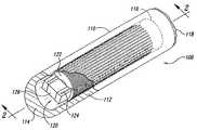
- FIG. 1is an isometric view of an implantable wireless marker in accordance with an embodiment of the invention with a section cut away to illustrate internal components.
- FIG. 2is a cross-sectional view taken along a longitudinal axis of an embodiment of the marker of FIG. 1 .
- FIG. 3is a cross-sectional view in a plane normal to a longitudinal axis of a marker in accordance with an embodiment of the marker shown in FIG. 1 .
- FIG. 4is a cross-sectional view taken along a longitudinal axis of a marker in accordance with an embodiment of the invention after being implanted in a patient.
- FIG. 5is a diagram of a display of a magnetic resonance image with an artifact by a magnetic marker.
- FIG. 6is a cross-sectional view taken along a longitudinal axis of a marker in accordance with another embodiment of the invention.
- FIGS. 1-6Several embodiments and features of markers in accordance with the invention are set forth and described in FIGS. 1-6 . It will be appreciated that other embodiments of markers in accordance with the invention can include additional or different features than those shown in FIGS. 1-6 . Additionally, it will be appreciated that several embodiments of markers in accordance with the invention do not include all of the features shown in these figures. Additionally, for purposes of brevity, like reference numbers refer to similar or identical components.
- FIG. 1is an isometric view of an implantable marker 100 in accordance with an embodiment of the invention with a portion cut away to illustrate internal components.
- the embodiment of the marker 100 shown in FIG. 1includes a casing 110 and a resonating circuit 120 in the casing 110 .
- the casing 110is a biocompatible barrier configured to be implanted in the patient or otherwise attached to the patient.
- the casing 110can be a generally cylindrical capsule that is sized to fit within a 14 gauge needle for percutaneous implantation, but the casing can have other configurations and be larger or smaller.
- the casing 110for example, can have barbs to anchor the casing 110 in soft tissue or an adhesive for attaching the casing 110 externally to the skin of a patient.
- the casing 110includes (a) a glass capsule or shell 112 having a closed end 114 and an open end 116 , and (b) a sealant 118 in the open end 116 of the shell 112 .
- the casing 110 and sealant 118can be made from plastics, ceramics, glass or other suitable biocompatible materials.
- the resonating circuit 120produces a wirelessly transmitted signal in response to a wirelessly transmitted excitation signal.
- the resonating circuit 120comprises a coil 122 defined by a plurality of windings of a conductor 124 .
- Many embodiments of the resonating circuit 120also include a capacitor 126 coupled to the coil 122 .
- the coil 122resonates at a selected resonant frequency.
- the coil 122can resonate at the selected resonant frequency solely using the parasitic capacitance of the windings without having a capacitor, or the selected resonant frequency can be produced using the combination of the coil 122 and the capacitor 126 .
- the coil 122by itself or in combination with the capacitor 126 accordingly defines a signal transmitter that generates an alternating magnetic field at the selected resonant frequency in response to the excitation signal.
- the conductor 124 of the illustrated embodimentcan be hot air or alcohol bonded wire having a gauge of approximately 45-52 gauge.
- the coil 122can have 800-2000 turns.
- the windingsare preferably wound in a tightly layered coil.
- the resonating circuit 120is powered by a wirelessly transmitted excitation signal such that the resonating circuit is leadless, i.e., not connected to external lead wires which extend through or project from the casing 110 .
- the resonating circuit 120can be energized by an alternating excitation magnetic field generated externally with respect to the patient at the resonant frequency of the resonating circuit.
- the resonating circuit 120produces a marker signal or response signal that can be measured by a sensor array positioned externally with respect to the patient. Suitable devices for generating the magnetic excitation field and sensing the marker signal are disclosed in U.S.
- FIG. 2is a cross-sectional view of an embodiment of the marker 100 taken along a longitudinal axis 2 - 2 shown in FIG. 1 .
- the marker 100further includes a ferromagnetic element 140 having a first end 142 and a second end 144 .
- the ferromagnetic element 140is at least partially surrounded by the coil 122 .
- the coil 122surrounds the ferromagnetic element 140 from the first end 142 to the second end 144 .
- the coil 122surrounds only a portion of the ferromagnetic element 140 .
- the capacitor 126can be positioned at the first end 142 of the ferromagnetic element 140 .
- the resonating circuit 120 and the ferromagnetic element 140can be fixed to the casing 110 by an adhesive 150 .
- the ferromagnetic element 140is preferably composed of ferrite or other materials that have high magnetic permeability compared to free space.
- the amount of energy that the inductor is capable of storingis limited, in part, by the magnetic field saturation of the ferromagnetic element 140 .
- the prior arttaught that the size of the ferromagnetic material should be maximized within the limited space of the marker. As shown in FIG. 2 , however, the volume of the ferromagnetic element 140 is significantly less than the available volume within the casing 110 .
- the smaller volume of the ferromagnetic element 140reduces the force exerted on the marker 100 when the marker 100 is placed in a magnetic resonance imaging device having a magnetic field strength of 1.5 T with a corresponding gradient field of approximately 3 T/m.
- the ferromagnetic elementhas a volume such that when the marker is in a magnetic resonance device, then the force exerted on the marker by the magnetic field is less than gravitational force exerted on the marker. Additionally, the small volume of the ferromagnetic element 140 reduces the size of the artifact in an image from a magnetic resonance device.
- ferromagnetic materialswill produce an artifact (i.e., a region in which image information is suppressed) in an image produced by a magnetic resonance imaging device.
- the volume of the ferromagnetic element 140can be reduced to a size such that it produces a small artifact in an image from a magnetic resonance device.
- such ferromagnetic elements 140have small diameters less than the size of commercially available ferrite rods for transponder applications, which are as small as 0.75 mm in diameter (i.e., ferrite rods available from Ferroxcube of Spain).
- FIG. 3is a cross-sectional view of the marker 100 taken along line 3 - 3 of FIG. 2 .
- the ferromagnetic element 140is a ferrite rod having a diameter D 1 of approximately 0.20-0.70 mm, but the ferromagnetic element 140 can have other cross-sectional configurations in other embodiments.
- an extruded ferrite rodcan have an elliptical, oval or polygonal cross section.
- the ferromagnetic element 140can have a length of approximately 2.0-20 mm.
- the ferromagnetic element 140has a diameter of approximately 0.25-0.50 mm and a length of 2-12 mm, and in another embodiment the ferromagnetic element 140 has a diameter of 0.30-0.35 mm and a length of 4.0-6.0 mm.
- the coil 122has an inner diameter of approximately 0.20-0.80 mm and an outer diameter D 2 of approximately 0.6-1.4 mm or 0.8-1.9 mm.
- the casing 110can have an outer diameter D 3 of approximately 1.0-3.0 mm. In other embodiments, the coil 122 can have different inner and outer diameters, and the casing 110 can have a different outer diameter.
- the diameter D 1 of the ferromagnetic element 140is approximately 0.30-0.50 mm
- the inner diameter of the coil 122is approximately 0.30-0.60 mm
- the outer diameter D 2 of the coil 122is approximately 1.2-1.9 mm (or 1.2-1.4 mm)
- the outer diameter D 3 of the casing 110is approximately 1.8-2.0 mm.
- the volume of the ferromagnetic element 140can be approximately 0.5-19.0 mm 3 .
- the marker 100is constructed by manufacturing the ferromagnetic element 140 , placing the coil 122 around the ferromagnetic element 140 , and encapsulating the resonating circuit 120 and the ferromagnetic element 140 in the casing 110 .
- the ferromagnetic element 140can be manufactured using extrusion, coring, or high pressure molding processes to form a ferrite rod having a diameter of approximately 0.2-0.7 mm.
- the coil 122is formed by winding the conductor 124 around either the ferromagnetic element 140 , a sleeve around the ferromagnetic element 140 , or a mandrel separate from the ferromagnetic element 140 .
- the conductor 124is wrapped directly onto the ferromagnetic element 140 , but this may not be feasible in many applications because it may break ferromagnetic elements having a diameter less than 0.5 mm.
- a retractable sleevecan slide along the ferromagnetic element 140 as the conductor 124 is wound directly onto the ferromagnetic element.
- the sleeveis expected to support the ferromagnetic element 140 as the first layer of turns are wrapped around the ferromagnetic element 140 .
- the first layer of turnssupports the rod so that subsequent layers of turns can be wound onto the first layer.
- the coil 122is wound around a mandrel separately from the ferromagnetic element 140 .
- the coil 122is then removed from the mandrel and the ferromagnetic element 140 is inserted into the inner diameter of the coil 122 .
- This embodimentcan result in a small gap between the ferromagnetic element 140 and the inner diameter of the coil 122 . This gap should be minimized in optimal circumstances to increase the performance of the resonating circuit 120 .
- this assemblyis adhered to the casing 110 using the adhesive 150 , and the sealant 118 is used to close the open end 116 of the casing 110 .
- FIG. 4is a representative view of the operation of the marker 100 in an magnetic field M generated by a magnetic resonance imaging device (not shown).
- the magnetic field Mis an imaging magnetic field.
- a patientis placed in a magnetic resonance imaging device to image a portion P of the patient.
- the imaging magnetic field Mincludes a plurality of flux lines F. Because the ferromagnetic element 140 has a high magnetic permeability, the ferromagnetic element 140 exerts a magnetic force F M in the presence of the magnetic field M due to the presence of DC and gradient magnetic fields.
- the magnitude of the magnetic force F Mis a function of the volume and the type of material (i.e. magnetic saturation) of the ferromagnetic element 140 .
- the volume of the ferromagnetic element 140is selected so that the magnetic force F M caused by the interaction between the ferromagnetic element 140 and the magnetic field M is less than the gravitational force FG exerted against the marker 100 . This will ensure that the magnetic field M does not cause the marker 100 to move within the portion P of the patient any more than the force of gravity will cause movement of the marker 100 .
- FIG. 5is a schematic representation of a magnetic resonance image 500 that shows a target location T within a body part of a patient.
- the image 500includes an artifact 510 caused by the ferromagnetic element 140 of the marker 100 .
- the artifact 510is typically much larger than the size of the marker, and thus it tends to obscure the actual location of the marker and the images of tissue adjacent to the marker.
- the size of the artifact 510is related to the size of the ferromagnetic element 140 in the marker 100 .
- the volume of the ferromagnetic element 140is selected to produce an artifact not greater than 1,500 mm 2 in an image produced by a resonance imaging device field having a DC field strength of 1.5 T.
- the volume of the ferromagnetic element 140is selected to produce an artifact not greater than 400-1,200 mm 2 , and in other cases not greater than 400-800 mm 2 in an image produced by a magnetic resonance imaging device field having a DC field strength of 1.5 T.
- FIG. 6is a cross-sectional view of a marker 600 in accordance with another embodiment of the invention.
- the marker 600is substantially similar to the marker 100 shown in FIG. 2 , but the marker 600 further includes a module 610 at the second end 144 of the ferromagnetic element 140 .
- the module 610is preferably configured to be symmetrical with respect to the capacitor 126 at the first end 142 of the ferromagnetic element 140 .
- the module 610more specifically, is configured to produce a similar radiographic image as the capacitor 126 in an x-ray.
- the module 610is configured such that the magnetic centroid of the marker is at least substantially coincident with the radiographic centroid of the marker.
- the module 610is configured to produce a symmetrical image relative to the capacitor 126 .
- the module 610can be another capacitor identical to the capacitor 126 that may or may not be electrically coupled to the coil 122 .
- the module 610can be an electrically inactive element that is not electrically connected to the resonating circuit 120 or another type of electrically active element that is electrically coupled to the resonating circuit 120 .
- Suitable electrically inactive modulesinclude ceramic blocks shaped like the capacitor 126 . In either case, one purpose of the module 610 is to have the same characteristics as the electrically active capacitor 126 in x-ray, CT, and other imaging techniques.
- the markersmay be located via radiographic methods (e.g. CT, or x-ray) to determine the marker centroid positions relative the target tissue prior to therapy, an error in the position of the marker radiographic and magnetic centroids may result in a fixed positional error during therapy.
- radiographic methodse.g. CT, or x-ray
Landscapes
- Health & Medical Sciences (AREA)
- Life Sciences & Earth Sciences (AREA)
- Engineering & Computer Science (AREA)
- Heart & Thoracic Surgery (AREA)
- Molecular Biology (AREA)
- Biophysics (AREA)
- Pathology (AREA)
- Biomedical Technology (AREA)
- Human Computer Interaction (AREA)
- Medical Informatics (AREA)
- Physics & Mathematics (AREA)
- Surgery (AREA)
- Animal Behavior & Ethology (AREA)
- General Health & Medical Sciences (AREA)
- Public Health (AREA)
- Veterinary Medicine (AREA)
- Magnetic Resonance Imaging Apparatus (AREA)
- Apparatus For Radiation Diagnosis (AREA)
Abstract
Description
Claims (41)
Priority Applications (8)
| Application Number | Priority Date | Filing Date | Title |
|---|---|---|---|
| US10/334,698US7289839B2 (en) | 2002-12-30 | 2002-12-30 | Implantable marker with a leadless signal transmitter compatible for use in magnetic resonance devices |
| US10/745,097US7778687B2 (en) | 2002-12-30 | 2003-12-23 | Implantable marker with a leadless signal transmitter compatible for use in magnetic resonance devices |
| JP2004565731AJP4616010B2 (en) | 2002-12-30 | 2003-12-24 | Implantable marker having a radio signal transmitter adapted for use in a magnetic resonance imaging apparatus and / or suitable for use in a radiation imaging process |
| AU2003300378AAU2003300378A1 (en) | 2002-12-30 | 2003-12-24 | Implantable marker with a wireless signal transmitter compatible for use in magnetic resonance imaging devices and/or suitable for use in radiation imaging processes |
| CA2512208ACA2512208C (en) | 2002-12-30 | 2003-12-24 | Implantable marker with a wireless signal transmitter compatible for use in magnetic resonance imaging devices and/or suitable for use in radiation imaging processes |
| PCT/US2003/041329WO2004061460A2 (en) | 2002-12-30 | 2003-12-24 | Implantable marker with a wireless signal transmitter compatible for use in magnetic resonance imaging devices and/or suitable for use in radiation imaging processes |
| EP03814967.0AEP1579224B1 (en) | 2002-12-30 | 2003-12-24 | Implantable marker with a wireless signal transmitter compatible for use in magnetic resonance imaging devices and/or suitable for use in radiation imaging processes |
| US11/862,980US8857043B2 (en) | 2002-12-30 | 2007-09-27 | Method of manufacturing an implantable marker with a leadless signal transmitter |
Applications Claiming Priority (1)
| Application Number | Priority Date | Filing Date | Title |
|---|---|---|---|
| US10/334,698US7289839B2 (en) | 2002-12-30 | 2002-12-30 | Implantable marker with a leadless signal transmitter compatible for use in magnetic resonance devices |
Related Child Applications (2)
| Application Number | Title | Priority Date | Filing Date |
|---|---|---|---|
| US10/745,097ContinuationUS7778687B2 (en) | 2002-12-30 | 2003-12-23 | Implantable marker with a leadless signal transmitter compatible for use in magnetic resonance devices |
| US11/862,980DivisionUS8857043B2 (en) | 2002-12-30 | 2007-09-27 | Method of manufacturing an implantable marker with a leadless signal transmitter |
Publications (2)
| Publication Number | Publication Date |
|---|---|
| US20040127787A1 US20040127787A1 (en) | 2004-07-01 |
| US7289839B2true US7289839B2 (en) | 2007-10-30 |
Family
ID=32655137
Family Applications (3)
| Application Number | Title | Priority Date | Filing Date |
|---|---|---|---|
| US10/334,698Expired - LifetimeUS7289839B2 (en) | 2002-12-30 | 2002-12-30 | Implantable marker with a leadless signal transmitter compatible for use in magnetic resonance devices |
| US10/745,097Expired - LifetimeUS7778687B2 (en) | 2002-12-30 | 2003-12-23 | Implantable marker with a leadless signal transmitter compatible for use in magnetic resonance devices |
| US11/862,980Expired - Fee RelatedUS8857043B2 (en) | 2002-12-30 | 2007-09-27 | Method of manufacturing an implantable marker with a leadless signal transmitter |
Family Applications After (2)
| Application Number | Title | Priority Date | Filing Date |
|---|---|---|---|
| US10/745,097Expired - LifetimeUS7778687B2 (en) | 2002-12-30 | 2003-12-23 | Implantable marker with a leadless signal transmitter compatible for use in magnetic resonance devices |
| US11/862,980Expired - Fee RelatedUS8857043B2 (en) | 2002-12-30 | 2007-09-27 | Method of manufacturing an implantable marker with a leadless signal transmitter |
Country Status (6)
| Country | Link |
|---|---|
| US (3) | US7289839B2 (en) |
| EP (1) | EP1579224B1 (en) |
| JP (1) | JP4616010B2 (en) |
| AU (1) | AU2003300378A1 (en) |
| CA (1) | CA2512208C (en) |
| WO (1) | WO2004061460A2 (en) |
Cited By (38)
| Publication number | Priority date | Publication date | Assignee | Title |
|---|---|---|---|---|
| US20060079764A1 (en)* | 2004-07-23 | 2006-04-13 | Wright J N | Systems and methods for real time tracking of targets in radiation therapy and other medical applications |
| US20060111646A1 (en)* | 2003-08-13 | 2006-05-25 | Gellman Barry N | Marking biopsy sites |
| US20070055090A1 (en)* | 2004-08-12 | 2007-03-08 | Navotek Medical Ltd. | Medical Treatment System and Method |
| US20070238946A1 (en)* | 2006-02-03 | 2007-10-11 | Chiodo Chris D | Specimen positioning system for imaging machines |
| US20080262473A1 (en)* | 2004-10-19 | 2008-10-23 | Navotek Medical Ltd. | Locating a Catheter Tip Using a Tracked Guide |
| US20090131734A1 (en)* | 2006-02-16 | 2009-05-21 | Navotek Medical Ltd. | Implantable medical marker and methods of preparation thereof |
| US20090127459A1 (en)* | 2004-08-12 | 2009-05-21 | Navotek Medical Ltd. | Localization of a Radioactive Source |
| US20090209804A1 (en)* | 2004-07-23 | 2009-08-20 | Calypso Medical Technologies, Inc. | Apparatuses and methods for percutaneously implanting objects in patients |
| US20090216115A1 (en)* | 2004-07-23 | 2009-08-27 | Calypso Medical Technologies, Inc. | Anchoring wirless markers within a human body |
| US20100042041A1 (en)* | 2008-08-18 | 2010-02-18 | Navotek Medical Ltd. | Implantation device for soft tissue markers and other implants |
| EP2272456A1 (en) | 2009-07-09 | 2011-01-12 | Siemens Aktiengesellschaft | Localization using non-metallic implantable fiducial markers |
| US7899513B2 (en) | 2004-07-23 | 2011-03-01 | Calypso Medical Technologies, Inc. | Modular software system for guided radiation therapy |
| US20110089246A1 (en)* | 2002-02-14 | 2011-04-21 | Ensid Investments Ltd | Method and apparatus for the manufacture of a tag |
| US8095203B2 (en) | 2004-07-23 | 2012-01-10 | Varian Medical Systems, Inc. | Data processing for real-time tracking of a target in radiation therapy |
| WO2012045092A2 (en) | 2010-10-01 | 2012-04-05 | Calypso Medical Technologies, Inc. | Delivery catheter for and method of delivering an implant, for example, bronchoscopically implanting a marker in a lung |
| US8164064B2 (en) | 2004-08-12 | 2012-04-24 | Navotek Medical Ltd. | Localization of a radioactive source within a body of a subject |
| US8175679B2 (en) | 2007-12-26 | 2012-05-08 | St. Jude Medical, Atrial Fibrillation Division, Inc. | Catheter electrode that can simultaneously emit electrical energy and facilitate visualization by magnetic resonance imaging |
| US20120199658A1 (en)* | 2008-05-21 | 2012-08-09 | Kikuo Kaga | Wireless identification tag |
| US8437449B2 (en) | 2004-07-23 | 2013-05-07 | Varian Medical Systems, Inc. | Dynamic/adaptive treatment planning for radiation therapy |
| US20160113729A1 (en)* | 2009-03-10 | 2016-04-28 | Medtronic Xomed, Inc. | Navigated Malleable Surgical Instrument |
| US9586059B2 (en) | 2004-07-23 | 2017-03-07 | Varian Medical Systems, Inc. | User interface for guided radiation therapy |
| US9675410B2 (en) | 2007-12-28 | 2017-06-13 | St. Jude Medical, Atrial Fibrillation Division, Inc. | Flexible polymer electrode for MRI-guided positioning and radio frequency ablation |
| US9730764B2 (en) | 2015-10-02 | 2017-08-15 | Elucent Medical, Inc. | Signal tag detection components, devices, and systems |
| US9919165B2 (en) | 2014-05-07 | 2018-03-20 | Varian Medical Systems, Inc. | Systems and methods for fiducial to plan association |
| US9943704B1 (en) | 2009-01-21 | 2018-04-17 | Varian Medical Systems, Inc. | Method and system for fiducials contained in removable device for radiation therapy |
| US10042013B2 (en) | 2012-02-14 | 2018-08-07 | Koninklijke Philips N.V. | Active position marker system for use in an MRI apparatus |
| US10043284B2 (en) | 2014-05-07 | 2018-08-07 | Varian Medical Systems, Inc. | Systems and methods for real-time tumor tracking |
| US10154799B2 (en) | 2016-08-12 | 2018-12-18 | Elucent Medical, Inc. | Surgical device guidance and monitoring devices, systems, and methods |
| US10182868B2 (en) | 2005-11-17 | 2019-01-22 | Varian Medical Systems, Inc. | Apparatus and methods for using an electromagnetic transponder in orthopedic procedures |
| US10195464B2 (en) | 2004-06-24 | 2019-02-05 | Varian Medical Systems, Inc. | Systems and methods for treating a lung of a patient using guided radiation therapy or surgery |
| US10245119B2 (en) | 2015-10-02 | 2019-04-02 | Elucent Medical, Inc. | Signal tag detection components, devices, and systems |
| US10278779B1 (en) | 2018-06-05 | 2019-05-07 | Elucent Medical, Inc. | Exciter assemblies |
| US20190231219A1 (en)* | 2015-09-08 | 2019-08-01 | Pacesetter, Inc. | Systems and methods for retrieving an implantable device |
| US10653496B2 (en) | 2005-09-19 | 2020-05-19 | Varian Medical Systems, Inc. | Apparatus and methods for implanting objects, such as a bronchoscopically implanting markers in the lung of patients |
| US11344382B2 (en) | 2014-01-24 | 2022-05-31 | Elucent Medical, Inc. | Systems and methods comprising localization agents |
| US11883063B2 (en) | 2013-04-26 | 2024-01-30 | Medtronic Xomed, Inc. | Medical device and its construction |
| US12226266B2 (en) | 2018-01-25 | 2025-02-18 | Endomagnetics Ltd | Systems and methods for detecting magnetic markers for surgical guidance |
| US12383349B2 (en) | 2022-07-26 | 2025-08-12 | Elucent Medical, Inc. | Systems and methods for wireless localization |
Families Citing this family (37)
| Publication number | Priority date | Publication date | Assignee | Title |
|---|---|---|---|---|
| EP2289423A1 (en)* | 1998-05-14 | 2011-03-02 | David N. Krag | System for bracketing tissue |
| US6363940B1 (en)* | 1998-05-14 | 2002-04-02 | Calypso Medical Technologies, Inc. | System and method for bracketing and removing tissue |
| EP2130511A1 (en) | 2000-11-17 | 2009-12-09 | Calypso Medical, Inc | System for locating and defining a target location within a human body |
| US7135978B2 (en) | 2001-09-14 | 2006-11-14 | Calypso Medical Technologies, Inc. | Miniature resonating marker assembly |
| US7289839B2 (en)* | 2002-12-30 | 2007-10-30 | Calypso Medical Technologies, Inc. | Implantable marker with a leadless signal transmitter compatible for use in magnetic resonance devices |
| JP4846582B2 (en)* | 2003-09-12 | 2011-12-28 | コーニンクレッカ フィリップス エレクトロニクス エヌ ヴィ | Method for locating a medical device with a microcoil |
| US8196589B2 (en)* | 2003-12-24 | 2012-06-12 | Calypso Medical Technologies, Inc. | Implantable marker with wireless signal transmitter |
| WO2005067563A2 (en)* | 2004-01-12 | 2005-07-28 | Calypso Medical Technologies, Inc. | Instruments with location markers and methods for tracking instruments through anatomical passageways |
| US7751866B2 (en)* | 2004-03-08 | 2010-07-06 | Olympus Corporation | Detecting system of position and posture of capsule medical device |
| JP5030392B2 (en)* | 2004-06-14 | 2012-09-19 | オリンパス株式会社 | Medical device position detection system and medical device guidance system |
| EP1982635B1 (en)* | 2006-01-19 | 2014-07-09 | Olympus Medical Systems Corp. | In vivo medical system |
| US7821402B2 (en)* | 2006-05-05 | 2010-10-26 | Quality Electrodynamics | IC tags/RFID tags for magnetic resonance imaging applications |
| EP1860458A1 (en) | 2006-05-22 | 2007-11-28 | Interuniversitair Microelektronica Centrum | Detection of resonant tags by UWB radar |
| US7676268B2 (en)* | 2006-11-30 | 2010-03-09 | Medtronic, Inc. | Medical methods and systems incorporating wireless monitoring |
| WO2008106552A1 (en) | 2007-02-28 | 2008-09-04 | Rf Surgical Systems, Inc. | Method, apparatus and article for detection of transponder tagged objects, for example during surgery |
| US8066715B2 (en)* | 2007-10-03 | 2011-11-29 | Cook Medical Technologies Llc | Magnetic stent removal |
| JP5008201B2 (en)* | 2008-05-21 | 2012-08-22 | 三智商事株式会社 | Wireless IC tag |
| WO2009151946A2 (en) | 2008-05-27 | 2009-12-17 | Rf Surgical Systems, Inc. | Multi-modal transponder and method and apparatus to detect same |
| JP5576869B2 (en) | 2008-09-30 | 2014-08-20 | アイメック | Pulse EPR detection |
| GB0906644D0 (en)* | 2009-04-17 | 2009-06-03 | Imec Inter Uni Micro Electr | Magnetic resonance imaging of single domain nano-particles |
| US8726911B2 (en) | 2008-10-28 | 2014-05-20 | Rf Surgical Systems, Inc. | Wirelessly detectable objects for use in medical procedures and methods of making same |
| US8264342B2 (en) | 2008-10-28 | 2012-09-11 | RF Surgical Systems, Inc | Method and apparatus to detect transponder tagged objects, for example during medical procedures |
| US9226686B2 (en) | 2009-11-23 | 2016-01-05 | Rf Surgical Systems, Inc. | Method and apparatus to account for transponder tagged objects used during medical procedures |
| US8971989B2 (en) | 2012-01-24 | 2015-03-03 | Covidien Lp | Magnetic field device for mapping and navigation in laparoscopic surgery |
| WO2015068069A1 (en) | 2013-11-06 | 2015-05-14 | Mediguide Ltd. | Magnetic field generator with minimal image occlusion and minimal impact on dimensions in c-arm x-ray environments |
| US9514341B2 (en) | 2014-03-31 | 2016-12-06 | Covidien Lp | Method, apparatus and article for detection of transponder tagged objects, for example during surgery |
| CN107205793B (en) | 2015-01-21 | 2021-09-14 | 柯惠Lp公司 | Detectable sponge for use in medical procedures and methods of making, packaging and accounting thereof |
| WO2016118755A1 (en) | 2015-01-21 | 2016-07-28 | Covidien Lp | Sterilizable wirelessly detectable objects for use in medical procedures and methods of making same |
| AU2016200928B2 (en) | 2015-02-26 | 2020-11-12 | Covidien Lp | Apparatuses to physically couple transponder to objects, such as surgical objects, and methods of using same |
| EP3098617A1 (en)* | 2015-05-29 | 2016-11-30 | Eidgenössische Technische Hochschule (ETH) | System for tracking position and orientation of an object in a magnetic resonance (mr) apparatus |
| CN106323846A (en)* | 2015-07-03 | 2017-01-11 | 先健科技(深圳)有限公司 | Method for monitoring corrosion degradation of bioabsorbable implant and for semi-quantification of relative weight loss ratio of corrosion product thereof |
| US11045626B2 (en) | 2016-03-06 | 2021-06-29 | Andrew N. Ellingson | Guide wire device and method |
| WO2018085822A1 (en)* | 2016-11-07 | 2018-05-11 | Synergistic Biosensors, LLC | Systems and methods for monitoring implantable devices for detection of implant failure utilizing wireless in vivo micro sensors |
| JP6931393B2 (en) | 2016-11-21 | 2021-09-01 | セント・ジュード・メディカル・インターナショナル・ホールディング・エスエーアールエルSt. Jude Medical International Holding S.a,r.l. | Perspective transparent magnetic field generator |
| US11730559B2 (en)* | 2019-12-16 | 2023-08-22 | Covidien Lp | RF tag with gravitationally aligned orientation |
| GB2612598B8 (en) | 2021-11-03 | 2025-02-12 | Endomagnetics Ltd | Magnetic markers for imaging and surgical guidance |
| GB2612597B8 (en)* | 2021-11-03 | 2025-02-12 | Endomagnetics Ltd | Improvements in or relating to implantable ferromagnetic markers |
Citations (155)
| Publication number | Priority date | Publication date | Assignee | Title |
|---|---|---|---|---|
| US3752960A (en) | 1971-12-27 | 1973-08-14 | C Walton | Electronic identification & recognition system |
| US3836842A (en) | 1973-01-22 | 1974-09-17 | Bell Canada Northern Electric | Encapsulated electrically resonant circuit and interrogating apparatus and method for finding same in various locations |
| US3967161A (en) | 1972-06-14 | 1976-06-29 | Lichtblau G J | A multi-frequency resonant tag circuit for use with an electronic security system having improved noise discrimination |
| US4017858A (en) | 1973-07-30 | 1977-04-12 | Polhemus Navigation Sciences, Inc. | Apparatus for generating a nutating electromagnetic field |
| US4023167A (en) | 1975-06-16 | 1977-05-10 | Wahlstrom Sven E | Radio frequency detection system and method for passive resonance circuits |
| US4065753A (en) | 1974-09-09 | 1977-12-27 | Minnesota Mining & Manufacturing Company | Electromagnetically responsive projectile and system for detecting same |
| US4114601A (en) | 1976-08-09 | 1978-09-19 | Micro Tec Instrumentation, Inc. | Medical and surgical implement detection system |
| US4123749A (en) | 1976-04-03 | 1978-10-31 | Bizerba-Werke Wilhelm Kraut Kg | Method and system for determining the presence of objects within a particular surveillance area, in particular for prevention of shoplifting |
| US4127110A (en) | 1976-05-24 | 1978-11-28 | Huntington Institute Of Applied Medical Research | Implantable pressure transducer |
| US4160971A (en) | 1975-05-02 | 1979-07-10 | National Research Development Corporation | Transponders |
| US4222374A (en) | 1978-06-16 | 1980-09-16 | Metal Bellows Corporation | Septum locating apparatus |
| US4230123A (en) | 1978-10-31 | 1980-10-28 | Hawkins Jr Irvin F | Needle sheath complex and process for decompression and biopsy |
| US4260990A (en) | 1979-11-08 | 1981-04-07 | Lichtblau G J | Asymmetrical antennas for use in electronic security systems |
| US4393872A (en) | 1980-05-27 | 1983-07-19 | Eder Instrument Co., Inc. | Aspirating surgical forceps |
| US4395910A (en) | 1980-09-22 | 1983-08-02 | Sonometric Systems, Inc. | Geometric correction circuit for ultrasonic scan display |
| US4466075A (en) | 1981-11-23 | 1984-08-14 | Siemens Gammasonics, Inc. | Motion correction circuitry and method for a radiation imaging device |
| US4618978A (en) | 1983-10-21 | 1986-10-21 | Cosman Eric R | Means for localizing target coordinates in a body relative to a guidance system reference frame in any arbitrary plane as viewed by a tomographic image through the body |
| US4633250A (en) | 1985-01-07 | 1986-12-30 | Allied Corporation | Coplanar antenna for proximate surveillance systems |
| US4642786A (en) | 1984-05-25 | 1987-02-10 | Position Orientation Systems, Ltd. | Method and apparatus for position and orientation measurement using a magnetic field and retransmission |
| US4643196A (en) | 1984-10-24 | 1987-02-17 | Hakko Electric Machine Works Co., Ltd. | Biopsy needle set |
| US4737794A (en) | 1985-12-09 | 1988-04-12 | Mcdonnell Douglas Corporation | Method and apparatus for determining remote object orientation and position |
| WO1988008282A1 (en) | 1987-04-27 | 1988-11-03 | Elekta Instrument Ab | Apparatus for marking an operating site |
| US4795995A (en) | 1984-09-17 | 1989-01-03 | Progressive Dynamics, Inc. | Method and apparatus for producing electromagnetic surveillance fields |
| US4799495A (en) | 1987-03-20 | 1989-01-24 | National Standard Company | Localization needle assembly |
| US4832055A (en) | 1988-07-08 | 1989-05-23 | Palestrant Aubrey M | Mechanically locking blood clot filter |
| US4849692A (en) | 1986-10-09 | 1989-07-18 | Ascension Technology Corporation | Device for quantitatively measuring the relative position and orientation of two bodies in the presence of metals utilizing direct current magnetic fields |
| US4909789A (en) | 1986-03-28 | 1990-03-20 | Olympus Optical Co., Ltd. | Observation assisting forceps |
| US4936823A (en) | 1988-05-04 | 1990-06-26 | Triangle Research And Development Corp. | Transendoscopic implant capsule |
| US4945305A (en) | 1986-10-09 | 1990-07-31 | Ascension Technology Corporation | Device for quantitatively measuring the relative position and orientation of two bodies in the presence of metals utilizing direct current magnetic fields |
| US4992794A (en) | 1988-10-10 | 1991-02-12 | Texas Instruments Incorporated | Transponder and method for the production thereof |
| US4994079A (en) | 1989-07-28 | 1991-02-19 | C. R. Bard, Inc. | Grasping forceps |
| US5031634A (en) | 1990-01-19 | 1991-07-16 | Beth Israel Hospital Assoc., Inc. | Adjustable biopsy needle-guide device |
| US5050608A (en) | 1988-07-12 | 1991-09-24 | Medirand, Inc. | System for indicating a position to be operated in a patient's body |
| US5062847A (en) | 1990-12-31 | 1991-11-05 | Barnes William E | Laparoscopic retractor |
| US5095224A (en) | 1990-08-31 | 1992-03-10 | Siemens-Pacesetter, Inc. | Interrupted resonance energy transfer system |
| US5099845A (en) | 1989-05-24 | 1992-03-31 | Micronix Pty Ltd. | Medical instrument location means |
| US5107862A (en) | 1991-05-06 | 1992-04-28 | Fabian Carl E | Surgical implement detector utilizing a powered marker |
| US5142292A (en) | 1991-08-05 | 1992-08-25 | Checkpoint Systems, Inc. | Coplanar multiple loop antenna for electronic article surveillance systems |
| US5170055A (en) | 1990-07-25 | 1992-12-08 | Care Wise Medical Products Corporation | Radiation detecting biopsy probe |
| US5188368A (en) | 1989-10-25 | 1993-02-23 | Saitek Limited | Electronic game apparatus |
| US5198877A (en) | 1990-10-15 | 1993-03-30 | Pixsys, Inc. | Method and apparatus for three-dimensional non-contact shape sensing |
| US5197466A (en) | 1983-01-21 | 1993-03-30 | Med Institute Inc. | Method and apparatus for volumetric interstitial conductive hyperthermia |
| US5205289A (en) | 1988-12-23 | 1993-04-27 | Medical Instrumentation And Diagnostics Corporation | Three-dimensional computer graphics simulation and computerized numerical optimization for dose delivery and treatment planning |
| US5211164A (en) | 1987-11-10 | 1993-05-18 | Allen George S | Method of locating a target on a portion of anatomy |
| US5211129A (en) | 1986-02-25 | 1993-05-18 | Destron/Idi, Inc. | Syringe-implantable identification transponder |
| US5221269A (en) | 1990-10-15 | 1993-06-22 | Cook Incorporated | Guide for localizing a nonpalpable breast lesion |
| US5223851A (en) | 1991-06-05 | 1993-06-29 | Trovan Limited | Apparatus for facilitating interconnection of antenna lead wires to an integrated circuit and encapsulating the assembly to form an improved miniature transponder device |
| US5230338A (en) | 1987-11-10 | 1993-07-27 | Allen George S | Interactive image-guided surgical system for displaying images corresponding to the placement of a surgical tool or the like |
| US5240011A (en) | 1991-11-27 | 1993-08-31 | Fischer Imaging Corporation | Motorized biopsy needle positioner |
| US5246005A (en) | 1991-07-02 | 1993-09-21 | Care Wise Medical Products Corporation | Apparatus and method for producing statistically valid discriminable signals |
| US5262772A (en) | 1989-08-16 | 1993-11-16 | Bio Medic Data Systems, Inc. | Transponder scanner |
| US5325873A (en) | 1992-07-23 | 1994-07-05 | Abbott Laboratories | Tube placement verifier system |
| US5377678A (en) | 1991-09-03 | 1995-01-03 | General Electric Company | Tracking system to follow the position and orientation of a device with radiofrequency fields |
| US5411026A (en) | 1993-10-08 | 1995-05-02 | Nomos Corporation | Method and apparatus for lesion position verification |
| US5417210A (en) | 1992-05-27 | 1995-05-23 | International Business Machines Corporation | System and method for augmentation of endoscopic surgery |
| US5425367A (en) | 1991-09-04 | 1995-06-20 | Navion Biomedical Corporation | Catheter depth, position and orientation location system |
| US5425382A (en) | 1993-09-14 | 1995-06-20 | University Of Washington | Apparatus and method for locating a medical tube in the body of a patient |
| US5446548A (en) | 1993-10-08 | 1995-08-29 | Siemens Medical Systems, Inc. | Patient positioning and monitoring system |
| US5453686A (en) | 1993-04-08 | 1995-09-26 | Polhemus Incorporated | Pulsed-DC position and orientation measurement system |
| WO1995033519A1 (en) | 1994-06-09 | 1995-12-14 | Elekta Instrument Ab | Positioning device and method for radiation treatment |
| WO1996008999A1 (en) | 1994-09-22 | 1996-03-28 | Lennernaes Bo | Use of implant with magnetic properties to determine the position of a patient |
| US5509900A (en) | 1992-03-02 | 1996-04-23 | Kirkman; Thomas R. | Apparatus and method for retaining a catheter in a blood vessel in a fixed position |
| US5515853A (en) | 1995-03-28 | 1996-05-14 | Sonometrics Corporation | Three-dimensional digital ultrasound tracking system |
| US5526812A (en) | 1993-06-21 | 1996-06-18 | General Electric Company | Display system for enhancing visualization of body structures during medical procedures |
| US5546951A (en) | 1993-07-20 | 1996-08-20 | Biosense, Inc. | Method and apparatus for studying cardiac arrhythmias |
| US5558091A (en) | 1993-10-06 | 1996-09-24 | Biosense, Inc. | Magnetic determination of position and orientation |
| US5617857A (en) | 1995-06-06 | 1997-04-08 | Image Guided Technologies, Inc. | Imaging system having interactive medical instruments and methods |
| US5622170A (en) | 1990-10-19 | 1997-04-22 | Image Guided Technologies, Inc. | Apparatus for determining the position and orientation of an invasive portion of a probe inside a three-dimensional body |
| US5622187A (en) | 1994-09-30 | 1997-04-22 | Nomos Corporation | Method and apparatus for patient positioning for radiation therapy |
| US5630431A (en) | 1991-06-13 | 1997-05-20 | International Business Machines Corporation | System and method for augmentation of surgery |
| US5645065A (en) | 1991-09-04 | 1997-07-08 | Navion Biomedical Corporation | Catheter depth, position and orientation location system |
| WO1997036192A1 (en) | 1996-03-27 | 1997-10-02 | Paul Scherrer Institut | Device and process for determining position |
| US5680106A (en) | 1995-10-27 | 1997-10-21 | International Business Machines Corporation | Multibit tag with stepwise variable frequencies |
| US5681326A (en) | 1993-06-15 | 1997-10-28 | Elekta Instrument Ab | Stereotactical instrument |
| US5697384A (en) | 1993-03-26 | 1997-12-16 | Surge Miyawaki Co., Ltd. | Internal identification apparatus for animals |
| WO1997048438A2 (en) | 1996-06-17 | 1997-12-24 | Lucent Medical Systems, Inc. | Medical tube for insertion and detection within the body of a patient |
| US5707390A (en) | 1990-03-02 | 1998-01-13 | General Surgical Innovations, Inc. | Arthroscopic retractors |
| US5707362A (en) | 1992-04-15 | 1998-01-13 | Yoon; Inbae | Penetrating instrument having an expandable anchoring portion for triggering protrusion of a safety member and/or retraction of a penetrating member |
| US5727552A (en) | 1996-01-11 | 1998-03-17 | Medtronic, Inc. | Catheter and electrical lead location system |
| US5745545A (en) | 1996-08-16 | 1998-04-28 | Siemens Medical Systems, Inc. | Alignment system and method for intra-operative radiation therapy |
| US5764052A (en) | 1995-06-16 | 1998-06-09 | Pacesetter, Inc. | Coil return energy measurement magnetic field sensor and method thereof |
| US5769861A (en) | 1995-09-28 | 1998-06-23 | Brainlab Med. Computersysteme Gmbh | Method and devices for localizing an instrument |
| US5779638A (en) | 1995-03-28 | 1998-07-14 | Sonometrics Corporation | Ultrasound-based 3-D tracking system using a digital signal processor |
| WO1998030166A1 (en) | 1997-01-08 | 1998-07-16 | Fabian Carl E | Surgical implement detector utilizing a smart marker |
| US5782775A (en) | 1995-10-20 | 1998-07-21 | United States Surgical Corporation | Apparatus and method for localizing and removing tissue |
| US5797849A (en) | 1995-03-28 | 1998-08-25 | Sonometrics Corporation | Method for carrying out a medical procedure using a three-dimensional tracking and imaging system |
| US5815076A (en) | 1996-01-16 | 1998-09-29 | Sensormatic Electronics Corporation | Pulsed-signal magnetomechanical electronic article surveillance system with improved damping of transmitting antenna |
| US5817022A (en) | 1995-03-28 | 1998-10-06 | Sonometrics Corporation | System for displaying a 2-D ultrasound image within a 3-D viewing environment |
| US5817092A (en) | 1995-11-09 | 1998-10-06 | Radio Therapeutics Corporation | Apparatus, system and method for delivering radio frequency energy to a treatment site |
| US5820553A (en) | 1996-08-16 | 1998-10-13 | Siemens Medical Systems, Inc. | Identification system and method for radiation therapy |
| US5823192A (en) | 1996-07-31 | 1998-10-20 | University Of Pittsburgh Of The Commonwealth System Of Higher Education | Apparatus for automatically positioning a patient for treatment/diagnoses |
| US5828770A (en) | 1996-02-20 | 1998-10-27 | Northern Digital Inc. | System for determining the spatial position and angular orientation of an object |
| US5830144A (en) | 1995-03-28 | 1998-11-03 | Vesely; Ivan | Tracking data sheath |
| US5840148A (en) | 1995-06-30 | 1998-11-24 | Bio Medic Data Systems, Inc. | Method of assembly of implantable transponder |
| US5868673A (en) | 1995-03-28 | 1999-02-09 | Sonometrics Corporation | System for carrying out surgery, biopsy and ablation of a tumor or other physical anomaly |
| US5868675A (en) | 1989-10-05 | 1999-02-09 | Elekta Igs S.A. | Interactive system for local intervention inside a nonhumogeneous structure |
| US5879297A (en) | 1997-05-08 | 1999-03-09 | Lucent Medical Systems, Inc. | System and method to determine the location and orientation of an indwelling medical device |
| US5879357A (en) | 1995-10-20 | 1999-03-09 | United States Surgical Corporation | Apparatus for marking tissue location |
| WO1999013775A1 (en) | 1997-09-12 | 1999-03-25 | Imagyn Medical Technologies California, Inc. | Incisional breast biopsy device |
| WO1999017133A1 (en) | 1997-09-26 | 1999-04-08 | Northern Digital Incorporated | A system for determining the spatial position of a target |
| US5895235A (en) | 1995-04-12 | 1999-04-20 | Em Microelectronic-Marin Sa | Process for manufacturing transponders of small dimensions |
| US5902238A (en) | 1993-09-14 | 1999-05-11 | University Of Washington | Medical tube and apparatus for locating the same in the body of a patient |
| US5902310A (en) | 1996-08-12 | 1999-05-11 | Ethicon Endo-Surgery, Inc. | Apparatus and method for marking tissue |
| US5907395A (en) | 1997-06-06 | 1999-05-25 | Image Guided Technologies, Inc. | Optical fiber probe for position measurement |
| US5910144A (en) | 1998-01-09 | 1999-06-08 | Endovascular Technologies, Inc. | Prosthesis gripping system and method |
| WO1999030182A1 (en) | 1997-12-05 | 1999-06-17 | Northern Digital Inc. | A system for determining the spatial position and orientation of a body |
| US5913820A (en) | 1992-08-14 | 1999-06-22 | British Telecommunications Public Limited Company | Position location system |
| WO1999035966A1 (en) | 1998-01-14 | 1999-07-22 | Leonard Reiffel | System to stabilize an irradiated internal target |
| WO1999044506A1 (en) | 1998-03-03 | 1999-09-10 | Senorx, Inc. | Breast biopsy system and method |
| US5951481A (en) | 1996-09-20 | 1999-09-14 | Critikon Company, L.L.C. | Apparatus and method for non-invasive measurement of a substance |
| US5963132A (en) | 1996-10-11 | 1999-10-05 | Avid Indentification Systems, Inc. | Encapsulated implantable transponder |
| WO1999027839A9 (en) | 1997-12-01 | 1999-10-21 | Eric R Cosman | Surgical positioning system |
| WO1999058065A1 (en) | 1998-05-14 | 1999-11-18 | Krag, David, N. | System and method for bracketing and removing tissue |
| WO1999058055A1 (en) | 1998-05-08 | 1999-11-18 | Sonometrics Corporation | A method for carrying out a medical procedure using a three-dimensional tracking and imaging system |
| US5989265A (en) | 1995-03-08 | 1999-11-23 | Bouquet De La Joliniere; Jean Henri | Device for pinpointing suspect lesions of the breast and apparatus for positioning it |
| US6015390A (en) | 1998-06-12 | 2000-01-18 | D. Krag Llc | System and method for stabilizing and removing tissue |
| US6019725A (en) | 1997-03-07 | 2000-02-01 | Sonometrics Corporation | Three-dimensional tracking and imaging system |
| US6026818A (en) | 1998-03-02 | 2000-02-22 | Blair Port Ltd. | Tag and detection device |
| WO2000019908A1 (en) | 1998-10-02 | 2000-04-13 | Boston Scientific Limited | Steerable transducer array for intracardial ultrasonic imaging |
| US6052477A (en) | 1993-02-12 | 2000-04-18 | George S. Allen | Automatic technique for localizing externally attached fiducial markers in volume images of the head |
| WO2000024332A1 (en) | 1998-10-23 | 2000-05-04 | Cortese Armand F | Marker for indicating the location of identified tissue |
| US6059734A (en) | 1995-01-06 | 2000-05-09 | Yoon; Inbae | Methods of collecting tissue at obstructed anatomical sites |
| US6064904A (en) | 1997-11-28 | 2000-05-16 | Picker International, Inc. | Frameless stereotactic CT scanner with virtual needle display for planning image guided interventional procedures |
| US6067465A (en) | 1997-11-26 | 2000-05-23 | General Electric Company | System and method for detecting and tracking reference position changes with linear phase shift in magnetic resonance imaging |
| US6076008A (en) | 1990-10-19 | 2000-06-13 | St. Louis University | System for indicating the position of a surgical probe within a head on an image of the head |
| US6082366A (en) | 1995-09-05 | 2000-07-04 | Aesculap Meditec Gmbh | Method and arrangement for determining the position of a marker in an organic cavity |
| US6094007A (en) | 1997-07-18 | 2000-07-25 | Image Guided Technologies, Inc. | Optical tracking system |
| US6097994A (en) | 1996-09-30 | 2000-08-01 | Siemens Corporate Research, Inc. | Apparatus and method for determining the correct insertion depth for a biopsy needle |
| US6097007A (en) | 1999-03-31 | 2000-08-01 | Eiko Electric Products Corp. | Aquarium water temperature controller |
| WO2000012009A8 (en) | 1998-09-01 | 2000-08-03 | Senorx Inc | Securing surgical instruments at target tissue sites |
| US6129658A (en) | 1997-12-10 | 2000-10-10 | Varian Associates, Inc. | Method and apparatus creating a radioactive layer on a receiving substrate for in vivo implantation |
| US6130612A (en) | 1997-01-05 | 2000-10-10 | Intermec Ip Corp. | Antenna for RF tag with a magnetoelastic resonant core |
| US6140740A (en) | 1997-12-30 | 2000-10-31 | Remon Medical Technologies, Ltd. | Piezoelectric transducer |
| US6144875A (en) | 1999-03-16 | 2000-11-07 | Accuray Incorporated | Apparatus and method for compensating for respiratory and patient motion during treatment |
| WO2000051514B1 (en) | 1999-03-01 | 2000-11-30 | Lucent Medical Systems Inc | Magnetic anatomical marker and method of use |
| WO2000071047A1 (en) | 1999-05-21 | 2000-11-30 | Cook Urological, Inc. | Localization device with anchoring barbs |
| US6198963B1 (en) | 1996-07-17 | 2001-03-06 | Biosense, Inc. | Position confirmation with learn and test functions |
| WO2001034049A2 (en) | 1999-10-28 | 2001-05-17 | Medtronic Surgical Navigation Technologies | Surgical communication and power system |
| US6239724B1 (en) | 1997-12-30 | 2001-05-29 | Remon Medical Technologies, Ltd. | System and method for telemetrically providing intrabody spatial position |
| US6363982B1 (en) | 2000-04-21 | 2002-04-02 | Elmo D. Nixon, Jr. | Single or multiple mortising, tenoning and dovetail woodworking jig |
| US6371379B1 (en) | 1995-07-17 | 2002-04-16 | Flying Null Limited | Magnetic tags or markers |
| US6400338B1 (en) | 2000-01-11 | 2002-06-04 | Destron-Fearing Corporation | Passive integrated transponder tag with unitary antenna core |
| WO2001054765A3 (en) | 2000-01-31 | 2002-07-18 | Zmed Inc | Method and apparatus for alignment of medical radiation beams using a body frame |
| US6441741B1 (en) | 1999-05-17 | 2002-08-27 | Avid Identification Systems, Inc. | Overmolded transponder |
| US20020193685A1 (en) | 2001-06-08 | 2002-12-19 | Calypso Medical, Inc. | Guided Radiation Therapy System |
| US6518884B1 (en) | 1998-03-27 | 2003-02-11 | Matsushita Electric Industrial Co., Ltd. | Electric resonance element, detection apparatus and moving vehicle control system |
| US20030052785A1 (en) | 2001-09-14 | 2003-03-20 | Margo Gisselberg | Miniature resonating marker assembly |
| US20030088178A1 (en) | 2001-11-02 | 2003-05-08 | Owens Timothy R | Method and apparatus for computer modified magnetic resonance imaging |
| US20030117269A1 (en) | 2001-12-20 | 2003-06-26 | Dimmer Steven C. | System for excitation leadless miniature marker |
| US20030117270A1 (en) | 2001-12-20 | 2003-06-26 | Dimmer Steven C. | System for spatially adjustable excitation of leadless miniature marker |
| US20030192557A1 (en) | 1998-05-14 | 2003-10-16 | David Krag | Systems and methods for locating and defining a target location within a human body |
| US20040074974A1 (en) | 2000-07-19 | 2004-04-22 | Fujio Senba | Rfid tag housing structure, rfid tag installation structure and rfid tag communication method |
| US6734795B2 (en) | 2000-08-14 | 2004-05-11 | William Raymond Price | Location of lost dentures using RF transponders |
| EP1034738B1 (en) | 1999-03-11 | 2004-09-29 | Biosense Webster, Inc. | Position sensing based on ultrasound emission |
| US6812842B2 (en) | 2001-12-20 | 2004-11-02 | Calypso Medical Technologies, Inc. | System for excitation of a leadless miniature marker |
Family Cites Families (14)
| Publication number | Priority date | Publication date | Assignee | Title |
|---|---|---|---|---|
| JPS58101405A (en)* | 1981-12-11 | 1983-06-16 | Matsushita Electric Ind Co Ltd | Manufacture of inductor |
| JPH054269Y2 (en)* | 1986-12-26 | 1993-02-02 | ||
| US4994078A (en)* | 1988-02-17 | 1991-02-19 | Jarvik Robert K | Intraventricular artificial hearts and methods of their surgical implantation and use |
| FR2635259A1 (en) | 1988-08-11 | 1990-02-16 | Marthan Erick | Apparatus for locating the position of a metal piece in a human or animal body |
| SE9400987L (en) | 1994-03-24 | 1995-09-25 | Elekta Instr Ab | Device for detecting instruments |
| JPH10508504A (en) | 1994-09-16 | 1998-08-25 | バイオプシス メディカル インコーポレイテッド | Method and apparatus for identifying and marking tissue |
| US6122541A (en)* | 1995-05-04 | 2000-09-19 | Radionics, Inc. | Head band for frameless stereotactic registration |
| AU8035598A (en) | 1997-06-18 | 1999-01-04 | Kirin Beer Kabushiki Kaisha | Mold-resistant plants and method of construction of same |
| US6175760B1 (en) | 1998-02-17 | 2001-01-16 | University Of Iowa Research Foundation | Lesion localizer for nuclear medicine |
| EP1079724A1 (en) | 1998-05-13 | 2001-03-07 | Inbae Yoon | Penetrating endoscope and endoscopic surgical instrument with cmos image sensor and display |
| US6501981B1 (en) | 1999-03-16 | 2002-12-31 | Accuray, Inc. | Apparatus and method for compensating for respiratory and patient motions during treatment |
| US6416520B1 (en) | 1999-04-23 | 2002-07-09 | Sherwood Services Ag | Microdrive for probes |
| US7289839B2 (en) | 2002-12-30 | 2007-10-30 | Calypso Medical Technologies, Inc. | Implantable marker with a leadless signal transmitter compatible for use in magnetic resonance devices |
| US8196589B2 (en) | 2003-12-24 | 2012-06-12 | Calypso Medical Technologies, Inc. | Implantable marker with wireless signal transmitter |
- 2002
- 2002-12-30USUS10/334,698patent/US7289839B2/ennot_activeExpired - Lifetime
- 2003
- 2003-12-23USUS10/745,097patent/US7778687B2/ennot_activeExpired - Lifetime
- 2003-12-24WOPCT/US2003/041329patent/WO2004061460A2/enactiveApplication Filing
- 2003-12-24CACA2512208Apatent/CA2512208C/ennot_activeExpired - Fee Related
- 2003-12-24JPJP2004565731Apatent/JP4616010B2/ennot_activeExpired - Fee Related
- 2003-12-24AUAU2003300378Apatent/AU2003300378A1/ennot_activeAbandoned
- 2003-12-24EPEP03814967.0Apatent/EP1579224B1/ennot_activeExpired - Lifetime
- 2007
- 2007-09-27USUS11/862,980patent/US8857043B2/ennot_activeExpired - Fee Related
Patent Citations (176)
| Publication number | Priority date | Publication date | Assignee | Title |
|---|---|---|---|---|
| US3752960A (en) | 1971-12-27 | 1973-08-14 | C Walton | Electronic identification & recognition system |
| US3967161A (en) | 1972-06-14 | 1976-06-29 | Lichtblau G J | A multi-frequency resonant tag circuit for use with an electronic security system having improved noise discrimination |
| US3836842A (en) | 1973-01-22 | 1974-09-17 | Bell Canada Northern Electric | Encapsulated electrically resonant circuit and interrogating apparatus and method for finding same in various locations |
| US4017858A (en) | 1973-07-30 | 1977-04-12 | Polhemus Navigation Sciences, Inc. | Apparatus for generating a nutating electromagnetic field |
| US4065753A (en) | 1974-09-09 | 1977-12-27 | Minnesota Mining & Manufacturing Company | Electromagnetically responsive projectile and system for detecting same |
| US4160971A (en) | 1975-05-02 | 1979-07-10 | National Research Development Corporation | Transponders |
| US4023167A (en) | 1975-06-16 | 1977-05-10 | Wahlstrom Sven E | Radio frequency detection system and method for passive resonance circuits |
| US4123749A (en) | 1976-04-03 | 1978-10-31 | Bizerba-Werke Wilhelm Kraut Kg | Method and system for determining the presence of objects within a particular surveillance area, in particular for prevention of shoplifting |
| US4127110A (en) | 1976-05-24 | 1978-11-28 | Huntington Institute Of Applied Medical Research | Implantable pressure transducer |
| US4114601A (en) | 1976-08-09 | 1978-09-19 | Micro Tec Instrumentation, Inc. | Medical and surgical implement detection system |
| US4222374A (en) | 1978-06-16 | 1980-09-16 | Metal Bellows Corporation | Septum locating apparatus |
| US4230123A (en) | 1978-10-31 | 1980-10-28 | Hawkins Jr Irvin F | Needle sheath complex and process for decompression and biopsy |
| US4260990A (en) | 1979-11-08 | 1981-04-07 | Lichtblau G J | Asymmetrical antennas for use in electronic security systems |
| US4393872A (en) | 1980-05-27 | 1983-07-19 | Eder Instrument Co., Inc. | Aspirating surgical forceps |
| US4395910A (en) | 1980-09-22 | 1983-08-02 | Sonometric Systems, Inc. | Geometric correction circuit for ultrasonic scan display |
| US4466075A (en) | 1981-11-23 | 1984-08-14 | Siemens Gammasonics, Inc. | Motion correction circuitry and method for a radiation imaging device |
| US5197466A (en) | 1983-01-21 | 1993-03-30 | Med Institute Inc. | Method and apparatus for volumetric interstitial conductive hyperthermia |
| US4618978A (en) | 1983-10-21 | 1986-10-21 | Cosman Eric R | Means for localizing target coordinates in a body relative to a guidance system reference frame in any arbitrary plane as viewed by a tomographic image through the body |
| US4642786A (en) | 1984-05-25 | 1987-02-10 | Position Orientation Systems, Ltd. | Method and apparatus for position and orientation measurement using a magnetic field and retransmission |
| US4795995A (en) | 1984-09-17 | 1989-01-03 | Progressive Dynamics, Inc. | Method and apparatus for producing electromagnetic surveillance fields |
| US4643196A (en) | 1984-10-24 | 1987-02-17 | Hakko Electric Machine Works Co., Ltd. | Biopsy needle set |
| US4633250A (en) | 1985-01-07 | 1986-12-30 | Allied Corporation | Coplanar antenna for proximate surveillance systems |
| US4737794A (en) | 1985-12-09 | 1988-04-12 | Mcdonnell Douglas Corporation | Method and apparatus for determining remote object orientation and position |
| US5211129A (en) | 1986-02-25 | 1993-05-18 | Destron/Idi, Inc. | Syringe-implantable identification transponder |
| US4909789A (en) | 1986-03-28 | 1990-03-20 | Olympus Optical Co., Ltd. | Observation assisting forceps |
| US4849692A (en) | 1986-10-09 | 1989-07-18 | Ascension Technology Corporation | Device for quantitatively measuring the relative position and orientation of two bodies in the presence of metals utilizing direct current magnetic fields |
| US4945305A (en) | 1986-10-09 | 1990-07-31 | Ascension Technology Corporation | Device for quantitatively measuring the relative position and orientation of two bodies in the presence of metals utilizing direct current magnetic fields |
| US4799495A (en) | 1987-03-20 | 1989-01-24 | National Standard Company | Localization needle assembly |
| WO1988008282A1 (en) | 1987-04-27 | 1988-11-03 | Elekta Instrument Ab | Apparatus for marking an operating site |
| US5211164A (en) | 1987-11-10 | 1993-05-18 | Allen George S | Method of locating a target on a portion of anatomy |
| US5397329A (en) | 1987-11-10 | 1995-03-14 | Allen; George S. | Fiducial implant and system of such implants |
| US5230338A (en) | 1987-11-10 | 1993-07-27 | Allen George S | Interactive image-guided surgical system for displaying images corresponding to the placement of a surgical tool or the like |
| US4936823A (en) | 1988-05-04 | 1990-06-26 | Triangle Research And Development Corp. | Transendoscopic implant capsule |
| US4832055A (en) | 1988-07-08 | 1989-05-23 | Palestrant Aubrey M | Mechanically locking blood clot filter |
| US5050608A (en) | 1988-07-12 | 1991-09-24 | Medirand, Inc. | System for indicating a position to be operated in a patient's body |
| US4992794A (en) | 1988-10-10 | 1991-02-12 | Texas Instruments Incorporated | Transponder and method for the production thereof |
| US5205289A (en) | 1988-12-23 | 1993-04-27 | Medical Instrumentation And Diagnostics Corporation | Three-dimensional computer graphics simulation and computerized numerical optimization for dose delivery and treatment planning |
| US5099845A (en) | 1989-05-24 | 1992-03-31 | Micronix Pty Ltd. | Medical instrument location means |
| US4994079A (en) | 1989-07-28 | 1991-02-19 | C. R. Bard, Inc. | Grasping forceps |
| US5262772A (en) | 1989-08-16 | 1993-11-16 | Bio Medic Data Systems, Inc. | Transponder scanner |
| US5868675A (en) | 1989-10-05 | 1999-02-09 | Elekta Igs S.A. | Interactive system for local intervention inside a nonhumogeneous structure |
| US5188368A (en) | 1989-10-25 | 1993-02-23 | Saitek Limited | Electronic game apparatus |
| US5031634A (en) | 1990-01-19 | 1991-07-16 | Beth Israel Hospital Assoc., Inc. | Adjustable biopsy needle-guide device |
| US5707390A (en) | 1990-03-02 | 1998-01-13 | General Surgical Innovations, Inc. | Arthroscopic retractors |
| US5170055A (en) | 1990-07-25 | 1992-12-08 | Care Wise Medical Products Corporation | Radiation detecting biopsy probe |
| US5095224A (en) | 1990-08-31 | 1992-03-10 | Siemens-Pacesetter, Inc. | Interrupted resonance energy transfer system |
| US5221269A (en) | 1990-10-15 | 1993-06-22 | Cook Incorporated | Guide for localizing a nonpalpable breast lesion |
| USRE35816E (en) | 1990-10-15 | 1998-06-02 | Image Guided Technologies Inc. | Method and apparatus for three-dimensional non-contact shape sensing |
| US5198877A (en) | 1990-10-15 | 1993-03-30 | Pixsys, Inc. | Method and apparatus for three-dimensional non-contact shape sensing |
| US5987349A (en) | 1990-10-19 | 1999-11-16 | Image Guided Technologies, Inc. | Method for determining the position and orientation of two moveable objects in three-dimensional space |
| US5622170A (en) | 1990-10-19 | 1997-04-22 | Image Guided Technologies, Inc. | Apparatus for determining the position and orientation of an invasive portion of a probe inside a three-dimensional body |
| US6076008A (en) | 1990-10-19 | 2000-06-13 | St. Louis University | System for indicating the position of a surgical probe within a head on an image of the head |
| US5062847A (en) | 1990-12-31 | 1991-11-05 | Barnes William E | Laparoscopic retractor |
| US5107862A (en) | 1991-05-06 | 1992-04-28 | Fabian Carl E | Surgical implement detector utilizing a powered marker |
| US5223851A (en) | 1991-06-05 | 1993-06-29 | Trovan Limited | Apparatus for facilitating interconnection of antenna lead wires to an integrated circuit and encapsulating the assembly to form an improved miniature transponder device |
| US5630431A (en) | 1991-06-13 | 1997-05-20 | International Business Machines Corporation | System and method for augmentation of surgery |
| US5246005A (en) | 1991-07-02 | 1993-09-21 | Care Wise Medical Products Corporation | Apparatus and method for producing statistically valid discriminable signals |
| US5142292A (en) | 1991-08-05 | 1992-08-25 | Checkpoint Systems, Inc. | Coplanar multiple loop antenna for electronic article surveillance systems |
| US5377678A (en) | 1991-09-03 | 1995-01-03 | General Electric Company | Tracking system to follow the position and orientation of a device with radiofrequency fields |
| US5645065A (en) | 1991-09-04 | 1997-07-08 | Navion Biomedical Corporation | Catheter depth, position and orientation location system |
| US5425367A (en) | 1991-09-04 | 1995-06-20 | Navion Biomedical Corporation | Catheter depth, position and orientation location system |
| US5240011A (en) | 1991-11-27 | 1993-08-31 | Fischer Imaging Corporation | Motorized biopsy needle positioner |
| US5509900A (en) | 1992-03-02 | 1996-04-23 | Kirkman; Thomas R. | Apparatus and method for retaining a catheter in a blood vessel in a fixed position |
| US5707362A (en) | 1992-04-15 | 1998-01-13 | Yoon; Inbae | Penetrating instrument having an expandable anchoring portion for triggering protrusion of a safety member and/or retraction of a penetrating member |
| US5572999A (en) | 1992-05-27 | 1996-11-12 | International Business Machines Corporation | Robotic system for positioning a surgical instrument relative to a patient's body |
| US5417210A (en) | 1992-05-27 | 1995-05-23 | International Business Machines Corporation | System and method for augmentation of endoscopic surgery |
| US5325873A (en) | 1992-07-23 | 1994-07-05 | Abbott Laboratories | Tube placement verifier system |
| US5913820A (en) | 1992-08-14 | 1999-06-22 | British Telecommunications Public Limited Company | Position location system |
| US6052477A (en) | 1993-02-12 | 2000-04-18 | George S. Allen | Automatic technique for localizing externally attached fiducial markers in volume images of the head |
| US5697384A (en) | 1993-03-26 | 1997-12-16 | Surge Miyawaki Co., Ltd. | Internal identification apparatus for animals |
| US5453686A (en) | 1993-04-08 | 1995-09-26 | Polhemus Incorporated | Pulsed-DC position and orientation measurement system |
| US5681326A (en) | 1993-06-15 | 1997-10-28 | Elekta Instrument Ab | Stereotactical instrument |
| US5526812A (en) | 1993-06-21 | 1996-06-18 | General Electric Company | Display system for enhancing visualization of body structures during medical procedures |
| US5568809A (en) | 1993-07-20 | 1996-10-29 | Biosense, Inc. | Apparatus and method for intrabody mapping |
| US5546951A (en) | 1993-07-20 | 1996-08-20 | Biosense, Inc. | Method and apparatus for studying cardiac arrhythmias |
| US5902238A (en) | 1993-09-14 | 1999-05-11 | University Of Washington | Medical tube and apparatus for locating the same in the body of a patient |
| EP0719420B1 (en) | 1993-09-14 | 1999-11-24 | University of Washington | Apparatus and method for locating a medical tube in the body of a patient |
| US5425382A (en) | 1993-09-14 | 1995-06-20 | University Of Washington | Apparatus and method for locating a medical tube in the body of a patient |
| US5558091A (en) | 1993-10-06 | 1996-09-24 | Biosense, Inc. | Magnetic determination of position and orientation |
| US5446548A (en) | 1993-10-08 | 1995-08-29 | Siemens Medical Systems, Inc. | Patient positioning and monitoring system |
| US5411026A (en) | 1993-10-08 | 1995-05-02 | Nomos Corporation | Method and apparatus for lesion position verification |
| WO1995033519A1 (en) | 1994-06-09 | 1995-12-14 | Elekta Instrument Ab | Positioning device and method for radiation treatment |
| US6049587A (en) | 1994-06-09 | 2000-04-11 | Elekta Instruments Ab | Positioning device and method for radiation treatment |
| US5629967A (en) | 1994-06-09 | 1997-05-13 | Elekta Instrument Ab | Positioning device and method for radiation treatment |
| US5528651A (en) | 1994-06-09 | 1996-06-18 | Elekta Instrument Ab | Positioning device and method for radiation treatment |
| US5805661A (en) | 1994-06-09 | 1998-09-08 | Elekta Instrument Ab | Positioning device and method for radiation treatment |
| WO1996008999A1 (en) | 1994-09-22 | 1996-03-28 | Lennernaes Bo | Use of implant with magnetic properties to determine the position of a patient |
| US5622187A (en) | 1994-09-30 | 1997-04-22 | Nomos Corporation | Method and apparatus for patient positioning for radiation therapy |
| US6059734A (en) | 1995-01-06 | 2000-05-09 | Yoon; Inbae | Methods of collecting tissue at obstructed anatomical sites |
| US5989265A (en) | 1995-03-08 | 1999-11-23 | Bouquet De La Joliniere; Jean Henri | Device for pinpointing suspect lesions of the breast and apparatus for positioning it |
| US5868673A (en) | 1995-03-28 | 1999-02-09 | Sonometrics Corporation | System for carrying out surgery, biopsy and ablation of a tumor or other physical anomaly |
| US5797849A (en) | 1995-03-28 | 1998-08-25 | Sonometrics Corporation | Method for carrying out a medical procedure using a three-dimensional tracking and imaging system |
| US5515853A (en) | 1995-03-28 | 1996-05-14 | Sonometrics Corporation | Three-dimensional digital ultrasound tracking system |
| US5817022A (en) | 1995-03-28 | 1998-10-06 | Sonometrics Corporation | System for displaying a 2-D ultrasound image within a 3-D viewing environment |
| US5779638A (en) | 1995-03-28 | 1998-07-14 | Sonometrics Corporation | Ultrasound-based 3-D tracking system using a digital signal processor |
| US5830144A (en) | 1995-03-28 | 1998-11-03 | Vesely; Ivan | Tracking data sheath |
| US5895235A (en) | 1995-04-12 | 1999-04-20 | Em Microelectronic-Marin Sa | Process for manufacturing transponders of small dimensions |
| US5617857A (en) | 1995-06-06 | 1997-04-08 | Image Guided Technologies, Inc. | Imaging system having interactive medical instruments and methods |
| US5764052A (en) | 1995-06-16 | 1998-06-09 | Pacesetter, Inc. | Coil return energy measurement magnetic field sensor and method thereof |
| US5840148A (en) | 1995-06-30 | 1998-11-24 | Bio Medic Data Systems, Inc. | Method of assembly of implantable transponder |
| US6371379B1 (en) | 1995-07-17 | 2002-04-16 | Flying Null Limited | Magnetic tags or markers |
| US6082366A (en) | 1995-09-05 | 2000-07-04 | Aesculap Meditec Gmbh | Method and arrangement for determining the position of a marker in an organic cavity |
| US5769861A (en) | 1995-09-28 | 1998-06-23 | Brainlab Med. Computersysteme Gmbh | Method and devices for localizing an instrument |
| US5879357A (en) | 1995-10-20 | 1999-03-09 | United States Surgical Corporation | Apparatus for marking tissue location |
| US5782775A (en) | 1995-10-20 | 1998-07-21 | United States Surgical Corporation | Apparatus and method for localizing and removing tissue |
| US5680106A (en) | 1995-10-27 | 1997-10-21 | International Business Machines Corporation | Multibit tag with stepwise variable frequencies |
| US5817092A (en) | 1995-11-09 | 1998-10-06 | Radio Therapeutics Corporation | Apparatus, system and method for delivering radio frequency energy to a treatment site |
| US5727552A (en) | 1996-01-11 | 1998-03-17 | Medtronic, Inc. | Catheter and electrical lead location system |
| US5815076A (en) | 1996-01-16 | 1998-09-29 | Sensormatic Electronics Corporation | Pulsed-signal magnetomechanical electronic article surveillance system with improved damping of transmitting antenna |
| US5828770A (en) | 1996-02-20 | 1998-10-27 | Northern Digital Inc. | System for determining the spatial position and angular orientation of an object |
| WO1997036192A1 (en) | 1996-03-27 | 1997-10-02 | Paul Scherrer Institut | Device and process for determining position |
| US6385482B1 (en) | 1996-03-27 | 2002-05-07 | Mednetix Ag | Device and process for determining position |
| WO1997048438A2 (en) | 1996-06-17 | 1997-12-24 | Lucent Medical Systems, Inc. | Medical tube for insertion and detection within the body of a patient |
| US6198963B1 (en) | 1996-07-17 | 2001-03-06 | Biosense, Inc. | Position confirmation with learn and test functions |
| US5823192A (en) | 1996-07-31 | 1998-10-20 | University Of Pittsburgh Of The Commonwealth System Of Higher Education | Apparatus for automatically positioning a patient for treatment/diagnoses |
| US5902310A (en) | 1996-08-12 | 1999-05-11 | Ethicon Endo-Surgery, Inc. | Apparatus and method for marking tissue |
| US5745545A (en) | 1996-08-16 | 1998-04-28 | Siemens Medical Systems, Inc. | Alignment system and method for intra-operative radiation therapy |
| US5820553A (en) | 1996-08-16 | 1998-10-13 | Siemens Medical Systems, Inc. | Identification system and method for radiation therapy |
| US5951481A (en) | 1996-09-20 | 1999-09-14 | Critikon Company, L.L.C. | Apparatus and method for non-invasive measurement of a substance |
| US6097994A (en) | 1996-09-30 | 2000-08-01 | Siemens Corporate Research, Inc. | Apparatus and method for determining the correct insertion depth for a biopsy needle |
| US5963132A (en) | 1996-10-11 | 1999-10-05 | Avid Indentification Systems, Inc. | Encapsulated implantable transponder |
| US6130612A (en) | 1997-01-05 | 2000-10-10 | Intermec Ip Corp. | Antenna for RF tag with a magnetoelastic resonant core |
| WO1998030166A1 (en) | 1997-01-08 | 1998-07-16 | Fabian Carl E | Surgical implement detector utilizing a smart marker |
| US6019725A (en) | 1997-03-07 | 2000-02-01 | Sonometrics Corporation | Three-dimensional tracking and imaging system |
| US5879297A (en) | 1997-05-08 | 1999-03-09 | Lucent Medical Systems, Inc. | System and method to determine the location and orientation of an indwelling medical device |
| US5907395A (en) | 1997-06-06 | 1999-05-25 | Image Guided Technologies, Inc. | Optical fiber probe for position measurement |
| US6094007A (en) | 1997-07-18 | 2000-07-25 | Image Guided Technologies, Inc. | Optical tracking system |
| WO1999013775A1 (en) | 1997-09-12 | 1999-03-25 | Imagyn Medical Technologies California, Inc. | Incisional breast biopsy device |
| US5923417A (en) | 1997-09-26 | 1999-07-13 | Northern Digital Incorporated | System for determining the spatial position of a target |
| WO1999017133A1 (en) | 1997-09-26 | 1999-04-08 | Northern Digital Incorporated | A system for determining the spatial position of a target |
| US6067465A (en) | 1997-11-26 | 2000-05-23 | General Electric Company | System and method for detecting and tracking reference position changes with linear phase shift in magnetic resonance imaging |
| US6064904A (en) | 1997-11-28 | 2000-05-16 | Picker International, Inc. | Frameless stereotactic CT scanner with virtual needle display for planning image guided interventional procedures |
| WO1999027839A9 (en) | 1997-12-01 | 1999-10-21 | Eric R Cosman | Surgical positioning system |
| WO1999030182A1 (en) | 1997-12-05 | 1999-06-17 | Northern Digital Inc. | A system for determining the spatial position and orientation of a body |
| US6061644A (en) | 1997-12-05 | 2000-05-09 | Northern Digital Incorporated | System for determining the spatial position and orientation of a body |
| US6129658A (en) | 1997-12-10 | 2000-10-10 | Varian Associates, Inc. | Method and apparatus creating a radioactive layer on a receiving substrate for in vivo implantation |
| US6239724B1 (en) | 1997-12-30 | 2001-05-29 | Remon Medical Technologies, Ltd. | System and method for telemetrically providing intrabody spatial position |
| US6140740A (en) | 1997-12-30 | 2000-10-31 | Remon Medical Technologies, Ltd. | Piezoelectric transducer |
| US5910144A (en) | 1998-01-09 | 1999-06-08 | Endovascular Technologies, Inc. | Prosthesis gripping system and method |
| WO1999035966A1 (en) | 1998-01-14 | 1999-07-22 | Leonard Reiffel | System to stabilize an irradiated internal target |
| US6026818A (en) | 1998-03-02 | 2000-02-22 | Blair Port Ltd. | Tag and detection device |
| WO1999044506A1 (en) | 1998-03-03 | 1999-09-10 | Senorx, Inc. | Breast biopsy system and method |
| US6518884B1 (en) | 1998-03-27 | 2003-02-11 | Matsushita Electric Industrial Co., Ltd. | Electric resonance element, detection apparatus and moving vehicle control system |
| WO1999058055A1 (en) | 1998-05-08 | 1999-11-18 | Sonometrics Corporation | A method for carrying out a medical procedure using a three-dimensional tracking and imaging system |
| US6698433B2 (en) | 1998-05-14 | 2004-03-02 | Calypso Medical Technologies, Inc. | System and method for bracketing and removing tissue |
| WO1999058065A1 (en) | 1998-05-14 | 1999-11-18 | Krag, David, N. | System and method for bracketing and removing tissue |
| US20030192557A1 (en) | 1998-05-14 | 2003-10-16 | David Krag | Systems and methods for locating and defining a target location within a human body |
| US6363940B1 (en) | 1998-05-14 | 2002-04-02 | Calypso Medical Technologies, Inc. | System and method for bracketing and removing tissue |
| US6675810B2 (en) | 1998-05-14 | 2004-01-13 | Calypso Medical Technologies, Inc. | System and method for bracketing and removing tissue |
| US20010018594A1 (en) | 1998-05-14 | 2001-08-30 | Calypso Medical, Inc. | System and Method for Bracketing and Removing Tissue |
| US6015390A (en) | 1998-06-12 | 2000-01-18 | D. Krag Llc | System and method for stabilizing and removing tissue |
| US6401722B1 (en) | 1998-06-12 | 2002-06-11 | Calypso Medical Technologies, Inc. | Method for stabilizing and removing tissue |
| WO2000012009A8 (en) | 1998-09-01 | 2000-08-03 | Senorx Inc | Securing surgical instruments at target tissue sites |
| WO2000019908A1 (en) | 1998-10-02 | 2000-04-13 | Boston Scientific Limited | Steerable transducer array for intracardial ultrasonic imaging |
| WO2000024332A1 (en) | 1998-10-23 | 2000-05-04 | Cortese Armand F | Marker for indicating the location of identified tissue |
| US6173715B1 (en) | 1999-03-01 | 2001-01-16 | Lucent Medical Systems, Inc. | Magnetic anatomical marker and method of use |
| WO2000051514B1 (en) | 1999-03-01 | 2000-11-30 | Lucent Medical Systems Inc | Magnetic anatomical marker and method of use |
| EP1034738B1 (en) | 1999-03-11 | 2004-09-29 | Biosense Webster, Inc. | Position sensing based on ultrasound emission |
| US6144875A (en) | 1999-03-16 | 2000-11-07 | Accuray Incorporated | Apparatus and method for compensating for respiratory and patient motion during treatment |
| US6097007A (en) | 1999-03-31 | 2000-08-01 | Eiko Electric Products Corp. | Aquarium water temperature controller |
| US6441741B1 (en) | 1999-05-17 | 2002-08-27 | Avid Identification Systems, Inc. | Overmolded transponder |
| WO2000071047A1 (en) | 1999-05-21 | 2000-11-30 | Cook Urological, Inc. | Localization device with anchoring barbs |
| WO2001034049A2 (en) | 1999-10-28 | 2001-05-17 | Medtronic Surgical Navigation Technologies | Surgical communication and power system |
| US6474341B1 (en) | 1999-10-28 | 2002-11-05 | Surgical Navigation Technologies, Inc. | Surgical communication and power system |
| US6400338B1 (en) | 2000-01-11 | 2002-06-04 | Destron-Fearing Corporation | Passive integrated transponder tag with unitary antenna core |
| WO2001054765A3 (en) | 2000-01-31 | 2002-07-18 | Zmed Inc | Method and apparatus for alignment of medical radiation beams using a body frame |
| US6363982B1 (en) | 2000-04-21 | 2002-04-02 | Elmo D. Nixon, Jr. | Single or multiple mortising, tenoning and dovetail woodworking jig |
| US20040074974A1 (en) | 2000-07-19 | 2004-04-22 | Fujio Senba | Rfid tag housing structure, rfid tag installation structure and rfid tag communication method |
| US6734795B2 (en) | 2000-08-14 | 2004-05-11 | William Raymond Price | Location of lost dentures using RF transponders |
| WO2002100485A1 (en) | 2001-06-08 | 2002-12-19 | Calypso Medical Technologies, Inc. | Guided radiation therapy system |
| US20020193685A1 (en) | 2001-06-08 | 2002-12-19 | Calypso Medical, Inc. | Guided Radiation Therapy System |
| US20030052785A1 (en) | 2001-09-14 | 2003-03-20 | Margo Gisselberg | Miniature resonating marker assembly |
| US20030088178A1 (en) | 2001-11-02 | 2003-05-08 | Owens Timothy R | Method and apparatus for computer modified magnetic resonance imaging |
| US20030117269A1 (en) | 2001-12-20 | 2003-06-26 | Dimmer Steven C. | System for excitation leadless miniature marker |
| US20030117270A1 (en) | 2001-12-20 | 2003-06-26 | Dimmer Steven C. | System for spatially adjustable excitation of leadless miniature marker |
| US6812842B2 (en) | 2001-12-20 | 2004-11-02 | Calypso Medical Technologies, Inc. | System for excitation of a leadless miniature marker |
Non-Patent Citations (16)
| Title |
|---|
| Hsiao, K., "Fast Multi-Axis Tracking of Magnetically-Resonant Passive Tags: Methods and Applications," Feb. 2001, Massachusetts Institute of Technology, Dept. of Electrical Engineering and Computer Science. |
| International Search Report dated Apr. 13, 2001, PCT Application No. PCT/US00/31673. |
| International Search Report dated Jan. 24, 2003, PCT Application No. PCT/US02/29390. |
| International Search Report dated Jul. 16, 1999, PCT Application No. PCT/US99/10683. |
| International Search Report dated Jul. 3, 2001, PCT Application No. PCT/US00/31667. |
| International Search Report dated May 24, 2005, PCT Application No. PCT/US03/41329-related to the present application. |
| International Search Report dated Oct. 8, 2002, PCT Application No. PCT/US02/17876. |
| Kelley, William E., MD, Image-Guided Breast Biopsy: The ABBI* System, 1997, www.ussurg.com/health-care/procedures/abbi. |
| PCT Written Opinion dated Jul. 8, 2003, PCT Application No. PCT/US00/31667. |
| The World's Most Versatile Biopsy System Offered Only by USSC, ABBI* System Features, (C) 1997, United States Surgical Corporation, www.ussurg.com/health-care/procedures/abbi. |
| The World's Most Versatile Biopsy System Offered Only by USSC, ABBI* System Features, © 1997, United States Surgical Corporation, www.ussurg.com/health-care/procedures/abbi. |
| U.S. Appl. No. 10/416,827, filed Nov. 17, 2000, David Krag. |
| U.S. Appl. No. 10/745,097, filed Dec. 23, 2003, Steven C. Dimmer. |
| U.S. Appl. No. 10/745,104, filed Dec. 23, 2003, David Krag. |
| U.S. Appl. No. 10/746,888, filed Dec. 24, 2003, Margo Gisselberg. |
| U.S. Appl. No. 10/791,662, filed Mar. 2, 2004, David Krag. |
Cited By (66)
| Publication number | Priority date | Publication date | Assignee | Title |
|---|---|---|---|---|
| US8360327B2 (en)* | 2002-02-14 | 2013-01-29 | Ensid Investments Ltd. | Animal transponder tag |
| US20110089246A1 (en)* | 2002-02-14 | 2011-04-21 | Ensid Investments Ltd | Method and apparatus for the manufacture of a tag |
| US20060111646A1 (en)* | 2003-08-13 | 2006-05-25 | Gellman Barry N | Marking biopsy sites |
| US11439847B2 (en) | 2004-06-24 | 2022-09-13 | Varian Medical Systems, Inc. | Systems and methods for treating a lung of a patient using guided radiation therapy or surgery |
| US10195464B2 (en) | 2004-06-24 | 2019-02-05 | Varian Medical Systems, Inc. | Systems and methods for treating a lung of a patient using guided radiation therapy or surgery |
| US20090209804A1 (en)* | 2004-07-23 | 2009-08-20 | Calypso Medical Technologies, Inc. | Apparatuses and methods for percutaneously implanting objects in patients |
| US8095203B2 (en) | 2004-07-23 | 2012-01-10 | Varian Medical Systems, Inc. | Data processing for real-time tracking of a target in radiation therapy |
| US9238151B2 (en) | 2004-07-23 | 2016-01-19 | Varian Medical Systems, Inc. | Dynamic/adaptive treatment planning for radiation therapy |
| US20090216115A1 (en)* | 2004-07-23 | 2009-08-27 | Calypso Medical Technologies, Inc. | Anchoring wirless markers within a human body |
| US8437449B2 (en) | 2004-07-23 | 2013-05-07 | Varian Medical Systems, Inc. | Dynamic/adaptive treatment planning for radiation therapy |
| US9586059B2 (en) | 2004-07-23 | 2017-03-07 | Varian Medical Systems, Inc. | User interface for guided radiation therapy |
| US8239005B2 (en) | 2004-07-23 | 2012-08-07 | Varian Medical Systems, Inc. | Systems and methods for real-time tracking of targets in radiation therapy and other medical applications |
| US20060079764A1 (en)* | 2004-07-23 | 2006-04-13 | Wright J N | Systems and methods for real time tracking of targets in radiation therapy and other medical applications |
| US7899513B2 (en) | 2004-07-23 | 2011-03-01 | Calypso Medical Technologies, Inc. | Modular software system for guided radiation therapy |
| US8198600B2 (en) | 2004-08-12 | 2012-06-12 | Navotek Medical Ltd. | Localization of a radioactive source |
| US8239002B2 (en) | 2004-08-12 | 2012-08-07 | Novatek Medical Ltd. | Guiding a tool for medical treatment by detecting a source of radioactivity |
| US7952079B2 (en) | 2004-08-12 | 2011-05-31 | Navotek Medical Ltd. | Localization of a radioactive source |
| US20070055090A1 (en)* | 2004-08-12 | 2007-03-08 | Navotek Medical Ltd. | Medical Treatment System and Method |
| US8198588B2 (en) | 2004-08-12 | 2012-06-12 | Navotek Medical Ltd. | Localization of a radioactive source within a body of a subject |
| US8164064B2 (en) | 2004-08-12 | 2012-04-24 | Navotek Medical Ltd. | Localization of a radioactive source within a body of a subject |
| US20090127459A1 (en)* | 2004-08-12 | 2009-05-21 | Navotek Medical Ltd. | Localization of a Radioactive Source |
| US20080262473A1 (en)* | 2004-10-19 | 2008-10-23 | Navotek Medical Ltd. | Locating a Catheter Tip Using a Tracked Guide |
| US10653496B2 (en) | 2005-09-19 | 2020-05-19 | Varian Medical Systems, Inc. | Apparatus and methods for implanting objects, such as a bronchoscopically implanting markers in the lung of patients |
| US10182868B2 (en) | 2005-11-17 | 2019-01-22 | Varian Medical Systems, Inc. | Apparatus and methods for using an electromagnetic transponder in orthopedic procedures |
| US7865226B2 (en)* | 2006-02-03 | 2011-01-04 | Chiodo Chris D | Specimen positioning system for imaging machines |
| US20070238946A1 (en)* | 2006-02-03 | 2007-10-11 | Chiodo Chris D | Specimen positioning system for imaging machines |
| US20090131734A1 (en)* | 2006-02-16 | 2009-05-21 | Navotek Medical Ltd. | Implantable medical marker and methods of preparation thereof |
| US8175679B2 (en) | 2007-12-26 | 2012-05-08 | St. Jude Medical, Atrial Fibrillation Division, Inc. | Catheter electrode that can simultaneously emit electrical energy and facilitate visualization by magnetic resonance imaging |
| US8473029B2 (en) | 2007-12-26 | 2013-06-25 | St. Jude Medical, Atrial Fibrillation Division, Inc. | Catheter electrode that can simultaneously emit electrical energy and facilitate visualization by magnetic resonance imaging |
| US9675410B2 (en) | 2007-12-28 | 2017-06-13 | St. Jude Medical, Atrial Fibrillation Division, Inc. | Flexible polymer electrode for MRI-guided positioning and radio frequency ablation |
| US11331136B2 (en) | 2007-12-28 | 2022-05-17 | St. Jude Medical, Atrial Fibrillation Division, Inc. | Flexible polymer electrode for MRI-guided positioning and radio frequency ablation |
| US20120199658A1 (en)* | 2008-05-21 | 2012-08-09 | Kikuo Kaga | Wireless identification tag |
| US8514060B2 (en)* | 2008-05-21 | 2013-08-20 | Mitomo Corporation | Wireless identification tag |
| US7942843B2 (en) | 2008-08-18 | 2011-05-17 | Navotek Medical Ltd. | Implantation device for soft tissue markers and other implants |
| US20100042041A1 (en)* | 2008-08-18 | 2010-02-18 | Navotek Medical Ltd. | Implantation device for soft tissue markers and other implants |
| US9943704B1 (en) | 2009-01-21 | 2018-04-17 | Varian Medical Systems, Inc. | Method and system for fiducials contained in removable device for radiation therapy |
| US20160113729A1 (en)* | 2009-03-10 | 2016-04-28 | Medtronic Xomed, Inc. | Navigated Malleable Surgical Instrument |
| US20230081692A1 (en)* | 2009-03-10 | 2023-03-16 | Medtronic Xomed, Inc. | Flexible circuit sheet |
| EP2272456A1 (en) | 2009-07-09 | 2011-01-12 | Siemens Aktiengesellschaft | Localization using non-metallic implantable fiducial markers |
| US20110009736A1 (en)* | 2009-07-09 | 2011-01-13 | Maltz Jonathan S | Localization Using Non-Metallic Implantable Fiducial Markers |
| WO2012045092A2 (en) | 2010-10-01 | 2012-04-05 | Calypso Medical Technologies, Inc. | Delivery catheter for and method of delivering an implant, for example, bronchoscopically implanting a marker in a lung |
| US10293135B2 (en) | 2010-10-01 | 2019-05-21 | Varian Medical Systems, Inc. | Delivery catheter for and method of delivering implant, for example, bronchoscopically implanting a marker in a lung |
| US10042013B2 (en) | 2012-02-14 | 2018-08-07 | Koninklijke Philips N.V. | Active position marker system for use in an MRI apparatus |
| US11883063B2 (en) | 2013-04-26 | 2024-01-30 | Medtronic Xomed, Inc. | Medical device and its construction |
| US11344382B2 (en) | 2014-01-24 | 2022-05-31 | Elucent Medical, Inc. | Systems and methods comprising localization agents |
| US10043284B2 (en) | 2014-05-07 | 2018-08-07 | Varian Medical Systems, Inc. | Systems and methods for real-time tumor tracking |
| US9919165B2 (en) | 2014-05-07 | 2018-03-20 | Varian Medical Systems, Inc. | Systems and methods for fiducial to plan association |
| US20190231219A1 (en)* | 2015-09-08 | 2019-08-01 | Pacesetter, Inc. | Systems and methods for retrieving an implantable device |
| US10610126B2 (en)* | 2015-09-08 | 2020-04-07 | Pacesetter, Inc. | Systems and methods for retrieving an implantable device |
| US11786333B2 (en) | 2015-10-02 | 2023-10-17 | Elucent Medical, Inc. | Signal tag detection components, devices, and systems |
| US10245118B2 (en) | 2015-10-02 | 2019-04-02 | Elucent Medical, Inc. | Signal tag detection components, devices, and systems |
| US10751145B2 (en) | 2015-10-02 | 2020-08-25 | Elucent Medical, Inc. | Signal tag detection components, devices, and systems |
| US11135034B2 (en) | 2015-10-02 | 2021-10-05 | Elucent Medical, Inc. | Signal tag detection components, devices, and systems |
| US9730764B2 (en) | 2015-10-02 | 2017-08-15 | Elucent Medical, Inc. | Signal tag detection components, devices, and systems |
| US12245902B2 (en) | 2015-10-02 | 2025-03-11 | Elucent Medical, Inc. | Signal tag detection components, devices, and systems |
| US10245119B2 (en) | 2015-10-02 | 2019-04-02 | Elucent Medical, Inc. | Signal tag detection components, devices, and systems |
| US12357192B2 (en) | 2016-08-12 | 2025-07-15 | Elucent Medical, Inc. | Surgical device guidance and monitoring devices, systems, and methods |
| US10154799B2 (en) | 2016-08-12 | 2018-12-18 | Elucent Medical, Inc. | Surgical device guidance and monitoring devices, systems, and methods |
| US11298044B2 (en) | 2016-08-12 | 2022-04-12 | Elucent Medical, Inc. | Surgical device guidance and monitoring devices, systems, and methods |
| US12226266B2 (en) | 2018-01-25 | 2025-02-18 | Endomagnetics Ltd | Systems and methods for detecting magnetic markers for surgical guidance |
| US11666391B2 (en) | 2018-06-05 | 2023-06-06 | Elucent Medical, Inc. | Exciter assemblies |
| US12186029B2 (en) | 2018-06-05 | 2025-01-07 | Elucent Medical, Inc. | Exciter assemblies |
| US10278779B1 (en) | 2018-06-05 | 2019-05-07 | Elucent Medical, Inc. | Exciter assemblies |
| US11540885B2 (en) | 2018-06-05 | 2023-01-03 | Elucent Medical, Inc. | Orthogonally isolated exciter with field steering |
| US11185375B2 (en) | 2018-06-05 | 2021-11-30 | Elucent Medical, Inc. | Exciter assemblies |
| US12383349B2 (en) | 2022-07-26 | 2025-08-12 | Elucent Medical, Inc. | Systems and methods for wireless localization |
Also Published As
| Publication number | Publication date |
|---|---|
| JP4616010B2 (en) | 2011-01-19 |
| EP1579224A4 (en) | 2010-02-17 |
| WO2004061460A2 (en) | 2004-07-22 |
| AU2003300378A1 (en) | 2004-07-29 |
| US20040138554A1 (en) | 2004-07-15 |
| EP1579224B1 (en) | 2016-08-17 |
| US20040127787A1 (en) | 2004-07-01 |
| AU2003300378A8 (en) | 2004-07-29 |
| JP2006512163A (en) | 2006-04-13 |
| US20080021308A1 (en) | 2008-01-24 |
| CA2512208A1 (en) | 2004-07-22 |
| US7778687B2 (en) | 2010-08-17 |
| WO2004061460A3 (en) | 2005-07-07 |
| US8857043B2 (en) | 2014-10-14 |
| EP1579224A2 (en) | 2005-09-28 |
| CA2512208C (en) | 2015-02-10 |
Similar Documents
| Publication | Publication Date | Title |
|---|---|---|
| US7289839B2 (en) | Implantable marker with a leadless signal transmitter compatible for use in magnetic resonance devices | |
| US8196589B2 (en) | Implantable marker with wireless signal transmitter | |
| US7407054B2 (en) | Packaged systems for implanting markers in a patient and methods for manufacturing and using such systems | |
| US7295877B2 (en) | Encapsulated sensor with external antenna | |
| EP1778077B1 (en) | Wireless markers for anchoring within a human body | |
| JP2006512163A5 (en) | ||
| EP1761189B1 (en) | Inductor for catheter | |
| JP5582781B2 (en) | System for detecting the position of medical equipment | |
| US7135978B2 (en) | Miniature resonating marker assembly | |
| JP4468659B2 (en) | Device for performing medical procedures on tissue in a subject's body | |
| JP4286493B2 (en) | System for measuring temperature and system for adjusting temperature sensitivity | |
| JP4762919B2 (en) | Small coil on core with printed circuit | |
| JP2010540049A (en) | Tissue marker | |
| CN107106253A (en) | Pulsating light emission marking arrangement | |
| CN108348190A (en) | Signal label detection part, equipment and system | |
| CA2504613A1 (en) | Method and system for mounting an mps sensor on a catheter | |
| US20170095312A1 (en) | Markers including magnetic transponders with increased radiographic visibility | |
| US10646303B1 (en) | Method and apparatus for delineating the position of a specific tissue | |
| US20250302576A1 (en) | Biopsy site marker wireless-powered vibration |
Legal Events
| Date | Code | Title | Description |
|---|---|---|---|
| AS | Assignment | Owner name:CALYPSO MEDICAL TECHNOLOGIES, INC., WASHINGTON Free format text:TO CORRECT NAMES OF CONVEYING PARTIES AND AN INCORRECT APPLICATION NUMBER 10/335,067, REEL 013970 AND FRAME 0973.;ASSIGNORS:DIMMER, STEVEN C.;HADFORD, ERIC;REEL/FRAME:014549/0095 Effective date:20030328 | |
| STCF | Information on status: patent grant | Free format text:PATENTED CASE | |
| CC | Certificate of correction | ||
| CC | Certificate of correction | ||
| FPAY | Fee payment | Year of fee payment:4 | |
| AS | Assignment | Owner name:VARIAN MEDICAL SYSTEMS, INC., CALIFORNIA Free format text:ASSIGNMENT OF ASSIGNORS INTEREST;ASSIGNOR:CALYPSO MEDICAL TECHNOLOGIES, INC.;REEL/FRAME:027221/0245 Effective date:20111111 | |
| FEPP | Fee payment procedure | Free format text:PAT HOLDER NO LONGER CLAIMS SMALL ENTITY STATUS, ENTITY STATUS SET TO UNDISCOUNTED (ORIGINAL EVENT CODE: STOL); ENTITY STATUS OF PATENT OWNER: LARGE ENTITY | |
| FPAY | Fee payment | Year of fee payment:8 | |
| MAFP | Maintenance fee payment | Free format text:PAYMENT OF MAINTENANCE FEE, 12TH YEAR, LARGE ENTITY (ORIGINAL EVENT CODE: M1553); ENTITY STATUS OF PATENT OWNER: LARGE ENTITY Year of fee payment:12 |