US7289714B1 - Tubing wrap procedure - Google Patents
Tubing wrap procedureDownload PDFInfo
- Publication number
- US7289714B1 US7289714B1US11/526,952US52695206AUS7289714B1US 7289714 B1US7289714 B1US 7289714B1US 52695206 AUS52695206 AUS 52695206AUS 7289714 B1US7289714 B1US 7289714B1
- Authority
- US
- United States
- Prior art keywords
- tube
- cable
- tether
- fibers
- length
- Prior art date
- Legal status (The legal status is an assumption and is not a legal conclusion. Google has not performed a legal analysis and makes no representation as to the accuracy of the status listed.)
- Expired - Fee Related
Links
Images


Classifications
- G—PHYSICS
- G02—OPTICS
- G02B—OPTICAL ELEMENTS, SYSTEMS OR APPARATUS
- G02B6/00—Light guides; Structural details of arrangements comprising light guides and other optical elements, e.g. couplings
- G02B6/44—Mechanical structures for providing tensile strength and external protection for fibres, e.g. optical transmission cables
- G02B6/4439—Auxiliary devices
- G02B6/4471—Terminating devices ; Cable clamps
- G02B6/4472—Manifolds
- G02B6/4475—Manifolds with provision for lateral branching
Definitions
- the principles disclosed hereinrelate to fiber optic cable systems. More particularly, the present disclosure relates to fiber optic cable systems having main cables and branch cables.
- Passive optical networksare becoming prevalent in part because service providers want to deliver high bandwidth communication capabilities to customers. Passive optical networks are a desirable choice for delivering high speed communication data because they may not employ active electronic devices, such as amplifiers and repeaters, between a central office and a subscriber termination. The absence of active electronic devices may decrease network complexity and/or cost and may increase network reliability.
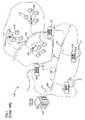
- FIG. 1illustrates a network 100 deploying passive fiber optic lines.
- the network 100may include a central office 110 that connects a number of end subscribers 115 (also called end users 115 herein) in a network.
- the central office 110may additionally connect to a larger network such as the Internet (not shown) and a public switched telephone network (PSTN).
- PSTNpublic switched telephone network
- the network 100may also include fiber distribution hubs (FDHs) 130 having one or more optical splitters (e.g., 1- to-8 splitters, 1-to-16 splitters, or 1-to-32 splitters) that generate a number of individual fibers that may lead to the premises of an end user 115 .
- the various lines of the networkcan be aerial or housed within underground conduits (e.g., see conduit 105 ).
- the portion of network 100 that is closest to central office 110is generally referred to as the F 1 region, where F 1 is the “feeder fiber” from the central office.
- the F 1 portion of the networkmay include a distribution cable having on the order of 12 to 48 fibers; however, alternative implementations may include fewer or more fibers.
- the portion of network 100 that includes an FDH 130 and a number of end users 115may be referred to as an F 2 portion of network 100 .
- Splitters used in an FDH 130may accept a feeder cable having a number of fibers and may split those incoming fibers into, for example, 216 to 432 individual distribution fibers that may be associated with a like number of end user locations.
- the network 100includes a plurality of breakout locations 125 at which branch cables (e.g., drop cables, stub cables, etc.) are separated out from main cables (e.g., distribution cables).
- Breakout locationscan also be referred to as tap locations or branch locations and branch cables can also be referred to as breakout cables.
- fibers of the branch cablesare typically spliced to selected fibers of the main cable.
- the interface between the fibers of the main cable and the fibers of the branch cablescan be connectorized.
- Stub cablesare typically branch cables that are routed from breakout locations to intermediate access locations such as a pedestals, drop terminals or hubs. Intermediate access locations can provide connector interfaces located between breakout locations and subscriber locations.
- a drop cableis a cable that typically forms the last leg to a subscriber location. For example, drop cables are routed from intermediate access locations to subscriber locations. Drop cables can also be routed directly from breakout locations to subscriber locations hereby bypassing any intermediate access locations
- Branch cablescan manually be separated out from a main cable in the field using field splices.
- Field splicesare typically housed within sealed splice enclosures. Formation of the sealed splice enclosures can be tiime consuming and expensive. There exists a need in the art for low-cost enclosures to protect cable branch (i.e., breakout) locations.
- Certain aspects of the disclosurerelate to fiber optic cable systems, packaging configurations and methods that facilitate the effective use and installation of pre-terminated fiber optic cable.
- inventive aspectscan relate to individual features and to combinations of features. It is to be understood that both the forgoing general description and the following detailed description are exemplary and explanatory only and are not restrictive of the broad inventive concepts upon which the embodiments disclosed herein are based.
- FIG. 1shows a prior art passive fiber optic network
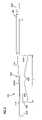
- FIG. 2is a side view of a tether branching from a distribution cable at a mid-span breakout location
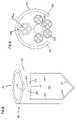
- FIG. 3is a cross-sectional view of an example distribution cable
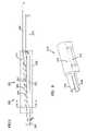
- FIG. 4is a cross-sectional view of an example tether cable
- FIG. 5is a side view of the tether and distribution cable of FIG. 2 with a tube and sleeve protecting the spliced optical fibers;
- FIG. 6is a front, perspective view of a retention block configured to secure a tether to a distribution cable
- FIG. 7is a bottom, cross-sectional view of the tube of FIG. 5 having a first end and a second end;
- FIG. 8is an enlarged view of the first end of the tube of FIG. 7 ;
- FIG. 9is a cross-sectional view taken along the 9 - 9 line of FIG. 5 ;
- FIG. 10shows an initial preparation of the distribution cable of FIG. 2 at the breakout location
- FIG. 11shows an initial preparation of the tether of FIG. 2 ;
- FIG. 12shows the prepared tether being coupled to the retention block of FIG. 6 .
- the present disclosurerelates to mid-span breakout arrangements provided on distribution cables.
- Each breakout arrangementis provided at a breakout location to protect the optical coupling of a tether to a distribution cable.
- a typical breakout location 260is provided at an intermediate point along the length of a distribution cable 220 (e.g., see FIG. 2 ).
- a tether 240branches from the distribution cable 220 at the breakout locator 260 .
- the fibers of the tether 240are optically coupled to the fibers of the distribution cable 220 .
- a typical distribution cableincludes a relatively large number of fibers (e.g., 72 , 144 or more fibers).
- the fibersare typically positioned in at least one buffer tube.
- the fibersare typically segregated into separate groups with each group contained within a separate buffer tube.
- the fibers within each buffer tubecan include either ribbon fibers or loose fibers.
- FIG. 3shows an example distribution cable 220 including six separate buffer tubes 222 each containing twelve fibers 224 dc .
- the buffer tubes 222may be gel filled.
- the distribution cable 220also includes a central strength member 226 for reinforcing the cable 220 , and an outer strength layer/member 228 such as aramid fiber/yarn (e.g., Kevlar®) for also reinforcing the cable 220 .
- the distribution cable 220further includes an outer jacket 230 that encloses the buffer tubes 222 . Ripcords 232 can be provided for facilitating tearing away portions of the jacket 230 to access the fibers 224 dc within the jacket 230 .
- the distribution cablecan include an outer jacket enclosing a single buffer tube and at least two strength members extending on opposite sides of the single buffer tube (not shown).
- An outer strength layer/membersuch as aramid fiber/yarn, can surround the single buffer tube within the jacket.
- the single buffer tubecan enclose loose fibers or ribbon fibers.
- a tether (e.g., a drop cable or a stub cable) 240branches out from the distribution cable 220 at the breakout location 260 (e.g., see FIG. 2 ).
- the outer jacket 230 of the distribution cableis stripped to expose at least one of the buffer tubes 222 at a stripped region 400 (see FIG. 2 ).
- the stripped region 400has a length L. In one embodiment, the stripped region 400 has a length L of about ten inches.
- One or more tether fibers(e.g., typically less than twelve fibers) 224 t ( FIG. 4 ) are optically coupled (e.g., spliced) at a coupling location 205 to selected fibers 224 dc of the distribution cable 220 extending from one of the exposed buffer tubes 222 (e.g., see FIG. 2 ).
- selected fibers 224 dc of the distribution cable 220extending from one of the exposed buffer tubes 222 (e.g., see FIG. 2 ).
- the opposite ends of the tether fibers 224 tare configured to optically couple to a drop terminal or other type of telecommunications equipment (not shown) offset from the breakout location 260 .
- the tether 240can terminate in one or more fiber optic connectors 256 (e.g., see FIG. 2 ).
- FIG. 4illustrates a tether cable 240 configured to join to the distribution cable 220 at the breakout location 260 .
- the tether 240is depicted as having a flat cable configuration.
- the flat cable configurationincludes a central buffer tube 242 containing a plurality of fibers 224 t (e.g., typically one to twelve loose or ribbonized fibers).
- Strength members 246e.g., flexible rods formed by glass fiber reinforced epoxy
- An outer jacket 250surrounds the strength members 246 and the buffer tube 242 .
- the outer jacket 250includes an outer perimeter having an elongated transverse cross-sectional shape. As shown at FIG. 4 , the transverse cross-sectional shape includes oppositely positioned, generally parallel sides 252 interconnected by rounded ends 254 .
- An additional strength layer 248e.g., aramid fiber/yarn
- a breakout assembly 200can be installed on the distribution cable 220 at the breakout location 260 to protect the optically coupled fibers 224 .
- the breakout assembly 200includes a sleeve 202 mounted over the coupling location 205 to protect the coupled optical fibers 224 dc , 224 t .
- the tether 240should preferably be able to withstand a pullout force of at least one hundred pounds.
- the breakout assembly 200also includes a retention block 270 (e.g., see FIGS. 5 and 6 ) configured to strengthen the mechanical interface between the tether 240 and the distribution cable 220 .
- FIG. 6shows an example retention block 270 including a base 274 and a cover 272 between which the fiber 224 t of the tether 240 extends.
- First and second protrusions 276 , 278extend from the cover 272 and base 274 , respectively.
- the retention block 270has a polycarbonate construction. Further details regarding the retention block 270 can be found in U.S. provisional application Ser. No. 60/781,280, filed Mar. 9, 2006, and entitled “FIBER OPTIC CABLE BREAKOUT CONFIGURATION,” the disclosure of which is hereby incorporated by reference.
- the fibers 224 t of the tether 240pre-terminated to the fibers 224 dc of the distribution cable 220 .
- Pre-terminatedmeans that the fibers 224 t are fused (e.g., spliced) or otherwise connected to the fibers 224 dc of the distribution cable 220 at the factory as part of the cable manufacturing process rather than being field terminated.
- the remainder of the breakout assembly 200is also preferably factory installed.
- the breakout assembly 200can also include a tube 300 having features that are examples of inventive aspects in accordance with the principles of the present disclosure.
- the tube 300has a body 310 extending from a first end 302 to a second end 304 .
- Example materials forming the tube body 310include Polyethylene, Fluorinated Ethylene Propylene (FEP), and other such plastics and/or resins.
- the tube body 310has a length L′ ( FIG. 7 ) that is less than the length L of the stripped region 400 ( FIG. 2 ). In one such embodiment, the tube body 310 has a length L′ that is about one inch less than the length L of the stripped region 400 . In certain embodiments, the tube body 310 has a diameter D ranging from about 1 ⁇ 4th of an inch to about a 1 ⁇ 2 inch. In one such embodiment, the diameter D of the tube body 310 is about 3 ⁇ 8 th of an inch and a wall thickness T is about 1/32 nd of an inch.
- the tube body 310defines an opening 312 adjacent the first end 302 of the tube 300 .
- the opening 312is sized and shaped to enable the first end 302 of the tube 300 to be inserted/mounted over the buffer tubes 222 of the distribution cable 220 (e.g., see FIGS. 5 and 9 ).
- the opening 312is configured to enable the fused optical fibers 224 to extend out of a buffer tube 222 of the distribution cable 220 , through the tube 300 , and to the retention block 270 (e.g., see FIG. 5 ).
- the opening 312is defined by five sides 311 , 313 , 315 , 317 , 319 .
- Sides 313 and 315are substantially parallel to one another.
- Side 311is generally perpendicular to sides 313 and 315 .
- Sides 317 and 319form a pointy end of the opening 312 .
- a slit 314extends from side 311 the opening 312 to the first end 302 of the tube 300 , thereby forming fingers 322 and 324 (e.g., see FIG. 8 ).
- the fingers 322 , 324are capable of flexing radially outwardly to mount to the buffer tubes 222 .
- the fingers 322 , 324substantially wrap around the circumference of the buffer tubes 222 (e.g., see FIG. 5 ). In other embodiments, however, the fingers 322 , 324 wrap around only a portion of the circumference of the buffer tubes 222 (e.g., FIG. 9 ).
- a notch 316is cut out of the periphery of the first end 302 of the tube at the slit 314 .
- the notch 316is defined by ramp surfaces that facilitate inserting the first end 302 of the tube 300 over the buffer tubes 222 .
- the notch 316can cause the fingers 322 , 324 to flex apart and wrap around at least a portion of the circumference of the buffer tubes 222 .
- a portion of the outer jacket 230is first stripped away to provide the stripped region 400 having a first end 402 and a second end 404 .
- portions of a cable nettingcan be removed adjacent the first and second ends 402 , 404 so that the buffer tubes 222 are exposed.
- the outer strength member 228can also be displaced (e.g., bunched at one side of the cable 220 ) adjacent the ends 402 , 404 to facilitate access to the buffer tubes 222 (not shown).
- Tape 406can be used to inhibit the intermediate length of netting that remains at the breakout location 260 from unraveling ( FIG. 10 ).
- One of the buffer tubes 222is then selected and a first window 408 is cut into the selected buffer tube 222 adjacent the first end 402 of the stripped region 400 and a second window 410 is cut into the buffer tube 222 adjacent the second end 404 of the stripped region 400 .
- the fibers 224 dc desired to be broken outare accessed and severed at the second window 410 .
- the fibers 224 dcare pulled from the buffer tube 222 through the first window 408 (see FIG. 10 ).
- the fibers 224 dcare ready to be terminated to a prepared tether 240 .
- a portion of the outer jacket 250is stripped away to expose the central buffer tube 242 and the strength members 246 (see FIG. 11 ). As shown at FIG. 11 , the central buffer tube 242 and the strength members 246 project outwardly beyond an end 247 of the outer jacket 250 .
- the strength layer 248has been removed from around the buffer tube 242 and is not shown. After removing the end portion of the outer jacket 250 , the strength members 246 are trimmed as shown at FIG. 12 , and an end portion of the central buffer tube 242 is removed to expose the fibers 224 t .
- the sleeve 202 and tube 300are first slid over the fibers 224 t of the tether 240 .
- the sleeve 202 and tube 300can be slid up over the buffer tube 242 and outer jacket 250 of the tether 240 .
- the fibers 224 t of the tetherare then optically coupled (e.g., spliced) to the fibers 224 dc of the distribution cable 220 .
- the sleeve 202can be slid over the coupling location 205 (see FIG. 5 ).
- the tube 300can be slid over the coupled fibers 224 and the sleeve 202 .
- the tether 240then can be mounted to the base 274 of the retention block 270 .
- the strength members 246can be positioned within side grooves 273 of the base 274 , and the central buffer tube 242 can be inserted within a central groove 275 of the base 274 .
- the central buffer tube 242has a length that extends beyond a first end of the base 274 , and the strength members 246 have lengths that terminate generally at the first end of the base 274 .
- the first end 302 of the tube 300is typically secured to the distribution cable 220 by wrapping the fingers 322 , 324 of the tube 300 around the buffer tubes 222 .
- the first end 302can be secured to the distribution cable 220 either before or after securing the retention block 270 to the distribution cable 220 .
- the second end 304can be mounted to the protrusions 276 , 278 of the retention block 270 .
- tapeis used to seal off the ends 302 , 304 of the tube 300 .
- two inch aluminum tapeis wrapped around the buffer tubes 222 and the tube 300 at both ends 302 , 304 of the tube 300 and adjacent the opening 312 . Additional lengths of tape can also be used to further secure the tube 300 to the distribution cable 220 .
- an enclosure 280( FIG. 5 ), such as an overmold, can be provided to enclose the breakout assembly 200 .
- the enclosure 280is preferably made of a flexible polymer plastic material. It is preferred for the enclosure 280 to be sized with a cross sectional shape sufficient to allow the breakout location to be readily passed through a one and one-half inch inner diameter conduit or a one and one-quarter inch diameter conduit.
- the breakout location 260has a cross sectional area that can be passed through a one inch inner diameter conduit.
Landscapes
- Physics & Mathematics (AREA)
- General Physics & Mathematics (AREA)
- Optics & Photonics (AREA)
- Light Guides In General And Applications Therefor (AREA)
Abstract
Description
Claims (12)
Priority Applications (1)
| Application Number | Priority Date | Filing Date | Title |
|---|---|---|---|
| US11/526,952US7289714B1 (en) | 2006-09-26 | 2006-09-26 | Tubing wrap procedure |
Applications Claiming Priority (1)
| Application Number | Priority Date | Filing Date | Title |
|---|---|---|---|
| US11/526,952US7289714B1 (en) | 2006-09-26 | 2006-09-26 | Tubing wrap procedure |
Publications (1)
| Publication Number | Publication Date |
|---|---|
| US7289714B1true US7289714B1 (en) | 2007-10-30 |
Family
ID=38623404
Family Applications (1)
| Application Number | Title | Priority Date | Filing Date |
|---|---|---|---|
| US11/526,952Expired - Fee RelatedUS7289714B1 (en) | 2006-09-26 | 2006-09-26 | Tubing wrap procedure |
Country Status (1)
| Country | Link |
|---|---|
| US (1) | US7289714B1 (en) |
Cited By (8)
| Publication number | Priority date | Publication date | Assignee | Title |
|---|---|---|---|---|
| US20070196068A1 (en)* | 2006-02-22 | 2007-08-23 | Julian Mullaney | Fiber optic cable systems and kits and methods for terminating the same |
| US7403685B2 (en)* | 2006-10-13 | 2008-07-22 | Adc Telecommunications, Inc. | Overmold zip strip |
| US20080247711A1 (en)* | 2007-04-03 | 2008-10-09 | Cody Joseph T | Attachment structure allowing movement and protection of a tether of a cable assembly |
| US7532799B2 (en) | 2007-04-12 | 2009-05-12 | Adc Telecommunications | Fiber optic telecommunications cable assembly |
| US7609925B2 (en) | 2007-04-12 | 2009-10-27 | Adc Telecommunications, Inc. | Fiber optic cable breakout configuration with tensile reinforcement |
| US20100158453A1 (en)* | 2008-12-22 | 2010-06-24 | Joseph Todd Cody | Distribution Cable Assembly Having Mid-Span Access Location |
| US8702326B2 (en) | 2012-03-23 | 2014-04-22 | Corning Cable Systems Llc | Splice protector for fiber optic ribbons |
| US9360624B2 (en) | 2013-03-22 | 2016-06-07 | Corning Optical Communications LLC | Splice protector for fiber optic ribbons |
Citations (148)
| Publication number | Priority date | Publication date | Assignee | Title |
|---|---|---|---|---|
| US2047152A (en) | 1932-10-22 | 1936-07-07 | Galvin Mfg Corp | Automobile radio cable |
| US3691505A (en) | 1970-08-20 | 1972-09-12 | Gen Electric | Heater cable splice and method of forming |
| US3845552A (en) | 1972-03-02 | 1974-11-05 | Method of making an encapsulated assembly | |
| US3879575A (en) | 1974-02-21 | 1975-04-22 | Bell Telephone Labor Inc | Encapsulating compound and closure |
| US3912854A (en) | 1970-01-26 | 1975-10-14 | John T Thompson | Encapsulated conductor junction |
| US3912855A (en) | 1973-04-20 | 1975-10-14 | John T Thompson | Encapsulating splice assembly |
| US4085286A (en) | 1974-09-27 | 1978-04-18 | Raychem Corporation | Heat-recoverable sealing article with self-contained heating means and method of sealing a splice therewith |
| US4107451A (en) | 1975-11-19 | 1978-08-15 | Trech, Inc. | Reinforced splice joint and method of making same |
| US4152539A (en) | 1977-10-21 | 1979-05-01 | Northern Telecom Limited | Telecommunication cable splices |
| US4322573A (en) | 1980-03-11 | 1982-03-30 | Northern Telecom Limited | Encapsulation of telecommunications cable splices |
| US4343844A (en) | 1980-11-17 | 1982-08-10 | Eaton Corporation | Shrinkable sleeve adapted for cable and tubing gas flow blocking |
| JPS58105114A (en) | 1981-12-17 | 1983-06-22 | Hitachi Cable Ltd | Optical fiber cable line with branch |
| US4405083A (en) | 1982-03-19 | 1983-09-20 | Northern Telecom Limited | Moulding apparatus for encapsulating cable splices |
| US4413881A (en) | 1979-07-26 | 1983-11-08 | Northern Telecom Limited | Optical fiber hermetic seal |
| EP0115725A1 (en) | 1982-12-28 | 1984-08-15 | Lignes Telegraphiques Et Telephoniques L.T.T. | Optical multipoint connection cable for information distribution, its production process and its application |
| US4467137A (en) | 1982-06-21 | 1984-08-21 | Raychem Limited | Cable breakout article |
| US4475935A (en) | 1981-07-24 | 1984-10-09 | Nippon Telegraph & Telephone Public Corporation | Joining method to obtain elongated coated optical fiber |
| US4481380A (en) | 1982-08-26 | 1984-11-06 | Alden Research Foundation | High voltage insulator for electrical components having telescoping insulative sleeves |
| US4490315A (en) | 1982-02-04 | 1984-12-25 | Northern Telecom Limited | Methods of moulding of plastics articles |
| US4512628A (en) | 1983-05-31 | 1985-04-23 | Gte Products Corporation | Splice casing assembly |
| US4528419A (en) | 1983-12-12 | 1985-07-09 | Northern Telecom Limited | Forming of cable splice closures |
| US4528150A (en) | 1982-09-23 | 1985-07-09 | Northern Telecom Limited | Methods and apparatus for sealing articles |
| US4549039A (en) | 1983-06-08 | 1985-10-22 | Northern Telecom Limited | Telecommunications cable splice closures |
| US4550220A (en) | 1983-11-04 | 1985-10-29 | National Industries, Inc. | Splice insulator assembly |
| JPS60169815U (en) | 1984-04-18 | 1985-11-11 | シャープ株式会社 | flyback transformer |
| JPS60169813U (en) | 1984-04-20 | 1985-11-11 | 株式会社 白金製作所 | Self-holding electromagnetic drive |
| US4556281A (en) | 1983-12-19 | 1985-12-03 | Gte Products Corporation | End plug for a fiber optic in-line splice case assembly |
| US4570032A (en) | 1984-09-07 | 1986-02-11 | Northern Telecom Limited | Sealing closure for a cable splice |
| US4581480A (en) | 1984-09-07 | 1986-04-08 | Northern Telecom Limited | Cable splice closure and strain relief |
| US4589939A (en) | 1984-02-17 | 1986-05-20 | Raychem Corporation | Insulating multiple-conductor cables using coated insert means |
| US4591330A (en) | 1984-11-05 | 1986-05-27 | Northern Telecom Limited | Moulding equipment |
| US4592721A (en) | 1982-09-23 | 1986-06-03 | Northern Telecom Limited | Apparatus for sealably encapsulating articles |
| US4595256A (en) | 1982-04-08 | 1986-06-17 | Les Cables De Lyon | Connection between the ends of two undersea optical fiber cables and method of manufacturing said connection |
| JPS6127510Y2 (en) | 1983-02-02 | 1986-08-15 | ||
| US4609773A (en) | 1985-07-08 | 1986-09-02 | Northern Telecom Limited | Seal assembly |
| JPS61220536A (en) | 1985-03-27 | 1986-09-30 | Hitachi Ltd | Information transmission line for car |
| US4625073A (en) | 1985-03-11 | 1986-11-25 | Raychem Corporation | Cable having a branch-off region sealed with a branch-off article and method of making same |
| JPS61190305U (en) | 1985-05-15 | 1986-11-27 | ||
| US4629597A (en) | 1985-07-08 | 1986-12-16 | Northern Telecom Limited | Forming of cable splice closures |
| US4648606A (en) | 1985-07-08 | 1987-03-10 | Northern Telecom Limited | Seals |
| US4648919A (en) | 1984-09-18 | 1987-03-10 | Raychem Corp. | Protection of cable splice |
| US4654474A (en) | 1985-06-19 | 1987-03-31 | Northern Telecom Limited | Forming of cable splice closures |
| DE3537684A1 (en) | 1985-10-23 | 1987-04-23 | Rheydt Kabelwerk Ag | Optical fibre cable branch and method for producing it |
| US4666537A (en) | 1980-04-24 | 1987-05-19 | Thomas & Betts Corporation | Method of sealing and repairing electrical cables |
| US4670069A (en) | 1984-09-18 | 1987-06-02 | Raychem Corp. | Protection of cable splice |
| US4670980A (en) | 1985-06-28 | 1987-06-09 | Northern Telecom Limited | Manufacture of sealing closures for a telecommunications cable splice |
| US4678866A (en) | 1985-07-08 | 1987-07-07 | Northern Telecom Limited | Forming of cable splice closures |
| US4684764A (en) | 1985-12-09 | 1987-08-04 | Amerace Corporation | High voltage cable splice protector |
| US4701574A (en) | 1985-02-06 | 1987-10-20 | Raychem Corp. | Cable sealing apparatus |
| JPS6254204B2 (en) | 1982-07-17 | 1987-11-13 | Toshiba Kiki Kk | |
| JPS6259906B2 (en) | 1982-03-31 | 1987-12-14 | Fujitsu Ltd | |
| US4725035A (en) | 1985-06-28 | 1988-02-16 | Northern Telecom Limited | Apparatus for manufacture of sealing closures for a telecommunications cable splice |
| US4732628A (en) | 1980-04-24 | 1988-03-22 | Thomas & Betts Corporation | Method of sealing and repairing electrical cables |
| US4747020A (en) | 1986-05-16 | 1988-05-24 | Adc Telecommunications, Inc. | Wire distribution apparatus |
| US4761052A (en) | 1986-01-31 | 1988-08-02 | N. V. Raychem S.A. | Optical fibre splice case |
| US4764232A (en) | 1986-09-26 | 1988-08-16 | Raychem Corporation | Method of protecting a cable splice with a splice closure having pressure measuring means |
| JPS63136007U (en) | 1987-02-25 | 1988-09-07 | ||
| JPS63180915U (en) | 1987-05-15 | 1988-11-22 | ||
| JPS63287916A (en) | 1987-05-21 | 1988-11-25 | Furukawa Electric Co Ltd:The | Terminal of composite cable |
| JPS63310317A (en) | 1987-06-11 | 1988-12-19 | Showa Electric Wire & Cable Co Ltd | Junction structural-unit for submaring cable |
| US4818824A (en) | 1987-08-19 | 1989-04-04 | American Telephone And Telegraph Company, At&T Bell Laboratories | Closure for aerial telephone cable splices |
| US4822434A (en) | 1986-07-10 | 1989-04-18 | Yazaki Corporation | Method for forming cover layer over wire joint |
| JPH0138828B2 (en) | 1986-09-18 | 1989-08-16 | Toyo Seikan Kaisha Ltd | |
| US4875952A (en) | 1984-06-11 | 1989-10-24 | American Telephone And Telegraph Company, At&T Bell Laboratories | Forced encapsulation means for a cable |
| US4884863A (en) | 1989-03-06 | 1989-12-05 | Siecor Corporation | Optical fiber splicing enclosure for installation in pedestals |
| US4913512A (en) | 1983-12-19 | 1990-04-03 | Gte Products Corporation | Fiber optic in-line splice case assembly |
| US4961623A (en) | 1989-09-05 | 1990-10-09 | Siecor Corporation | Preterminated optical cable |
| US4963698A (en) | 1985-05-02 | 1990-10-16 | Raychem Corporation | Cable sealing |
| US5004315A (en) | 1983-10-20 | 1991-04-02 | Furukawa Electric Co., Ltd. | Optical cable and optical cable line |
| US5042901A (en) | 1990-07-31 | 1991-08-27 | Siecor Corporation | Preconnectorized optical splice closure |
| US5046811A (en) | 1989-07-17 | 1991-09-10 | Jung Roger E | Junction box for optical communications cords, and gland assembly for cord |
| US5054868A (en) | 1990-08-29 | 1991-10-08 | The United States Of America As Represented By The Secretary Of The Navy | Armored optical fiber cable interconnection for dual payout systems |
| US5066095A (en) | 1990-02-09 | 1991-11-19 | Alcatel Cable | Jointing box for optical fiber cables |
| US5074808A (en) | 1991-02-06 | 1991-12-24 | Amp Incorporated | Molded strain relief in back shell |
| US5097529A (en) | 1991-03-22 | 1992-03-17 | At&T Bell Laboratories | Space-saving optical fiber cable closure |
| US5099088A (en) | 1989-07-19 | 1992-03-24 | Three Bond Co., Ltd. | Means for splicing wires |
| US5115105A (en) | 1990-02-21 | 1992-05-19 | Amphenol Corporation | Overbraided in-line data bus loom |
| US5121458A (en) | 1991-04-05 | 1992-06-09 | Alcatel Na Cable Systems, Inc. | Preterminated fiber optic cable |
| US5125060A (en) | 1991-04-05 | 1992-06-23 | Alcatel Na Cable Systems, Inc. | Fiber optic cable having spliceless fiber branch and method of making |
| US5185544A (en) | 1991-03-25 | 1993-02-09 | Mitsuba Electric Mfg. Co., Ltd. | Ventilation structure in a vertically mounted motor |
| US5194692A (en) | 1990-09-27 | 1993-03-16 | Amphenol Corporation | Uncased data bus coupler |
| US5210812A (en) | 1991-04-05 | 1993-05-11 | Alcatel Na Cable Systems, Inc. | Optical fiber cable having spliced fiber branch and method of making the same |
| US5215930A (en) | 1991-10-23 | 1993-06-01 | At&T Bell Laboratories | Integrated circuit etching of silicon nitride and polysilicon using phosphoric acid |
| US5217808A (en) | 1989-11-29 | 1993-06-08 | At&T Bell Laboratories | Water blocked cable portion and methods of making same |
| US5241611A (en) | 1989-10-04 | 1993-08-31 | British Telecommunications Public Limited Company | Cable joint |
| US5245151A (en) | 1989-04-07 | 1993-09-14 | Minnesota Mining And Manufacturing Company | Method and article for microwave bonding of splice closure |
| US5347089A (en) | 1990-06-22 | 1994-09-13 | Raychem Limited | Branch off |
| US5353367A (en) | 1993-11-29 | 1994-10-04 | Northern Telecom Limited | Distribution frame and optical connector holder combination |
| US5376196A (en) | 1991-07-11 | 1994-12-27 | Kabelmetal Electro Gmbh | Method for sealing the end of a heat-shrunk sleeve |
| US5378853A (en) | 1992-01-29 | 1995-01-03 | Filotex | Shielded multibranch harness |
| US5394502A (en) | 1993-12-21 | 1995-02-28 | United Technologies Corporation | Fiber optic cable harness break-out fitting |
| US5402515A (en) | 1994-03-01 | 1995-03-28 | Minnesota Mining And Manufacturing Company | Fiber distribution frame system, cabinets, trays and fiber optic connector couplings |
| US5410105A (en) | 1992-09-21 | 1995-04-25 | Nitto Denko Corporation | Method for waterproofing junction of main and branch wires and cover therefor |
| US5420958A (en) | 1990-05-21 | 1995-05-30 | Minnesota Mining And Manufacturing Company | Optical fiber distribution center |
| USRE34955E (en) | 1989-07-31 | 1995-05-30 | Adc Telecommunications, Inc. | Optical fiber distribution frame |
| US5440665A (en) | 1993-04-16 | 1995-08-08 | Raychem Corporation | Fiber optic cable system including main and drop cables and associated fabrication method |
| US5442726A (en) | 1994-02-22 | 1995-08-15 | Hubbell Incorporated | Optical fiber storage system |
| US5450517A (en) | 1994-07-01 | 1995-09-12 | The Whitaker Corporation | Re-enterable fiber optic splicer for data communications |
| US5491766A (en) | 1993-04-16 | 1996-02-13 | Raychem Corporation | Bonding assembly for fiber optic cable and associated method |
| US5509202A (en) | 1992-11-19 | 1996-04-23 | The United States Of America As Represented By The Secretary Of The Navy | Hydrostatic sealing sleeve method for utilizing wire connections |
| US5517592A (en) | 1993-10-22 | 1996-05-14 | Kabelmetal Electro Gmbh | Sleeve for branch or joint areas in optical or electrical cables |
| US5666453A (en) | 1994-07-15 | 1997-09-09 | Roy Witte | Fiber optic jumper cables and tracing method using same |
| US5684911A (en) | 1995-09-01 | 1997-11-04 | Lucent Technologies Inc. | Sub-surface fiber optic splice housing and method of splicing fiber optic cable |
| US5696864A (en) | 1996-09-18 | 1997-12-09 | Communications Technology Corporation | Aerial enclosure for coupling data signals to a customer site |
| US5734776A (en) | 1996-08-28 | 1998-03-31 | Adc Telecommunications, Inc. | Outside plant cross-connect apparatus |
| US5767448A (en) | 1996-09-30 | 1998-06-16 | Raychem Corporation | Sealing device |
| US5778122A (en) | 1996-12-24 | 1998-07-07 | Siecor Corporation | Fiber optic cable assembly for interconnecting optical fibers within a receptacle mounted within the wall of an enclosure |
| US5823646A (en) | 1997-09-02 | 1998-10-20 | Siecor Corporation | Door assembly for optical hardware cabinet |
| US5892870A (en) | 1995-11-16 | 1999-04-06 | Fiber Connections Inc. | Fibre optic cable connector |
| US5945633A (en) | 1996-05-23 | 1999-08-31 | The Siemon Company | Rack mountable cable distribution enclosure having an angled adapter plate bracket |
| US5969294A (en) | 1997-12-31 | 1999-10-19 | Siecor Operations, Llc | Fiber optic connector cabinet with rotatably mounted adapter panels |
| US5997186A (en) | 1998-05-13 | 1999-12-07 | Huynh; Van L. | Hybrid cable splice closure and related methods |
| USRE36592E (en) | 1994-07-01 | 2000-02-29 | Siecor Corporation | Optical receiver stub fitting |
| US6104846A (en) | 1998-07-31 | 2000-08-15 | Litton Systems, Inc. | System for splicing sensors into a multiple fiber optical cable |
| USRE37028E1 (en) | 1994-02-02 | 2001-01-23 | Siecor Corporation | Cable assembly for use with opto-electronic equipment enclosures |
| US6181861B1 (en) | 1997-02-14 | 2001-01-30 | Alcatel | Arrangement for branching a telecommunications cable containing several stranded elements with optical fibers |
| JP2001116968A (en) | 1999-08-11 | 2001-04-27 | Toyokuni Electric Cable Co Ltd | Optical communication trunk cable and branching tool for optical communication trunk cable |
| US6255584B1 (en) | 1994-12-13 | 2001-07-03 | Eurocopter | Shielded bundle of electrical conductors and process for producing it |
| US6376774B1 (en) | 1996-08-22 | 2002-04-23 | Littelfuse Inc. | Housing for cable assembly |
| US6407338B1 (en) | 1997-01-15 | 2002-06-18 | Uniseal, Inc. | Composite sealant and splice case therefor |
| US6466725B2 (en) | 2000-11-29 | 2002-10-15 | Corning Cable Systems Llc | Apparatus and method for splitting optical fibers |
| US6493500B1 (en) | 2000-09-19 | 2002-12-10 | Korea Telecom | Method for mid-span branching of optical fiber cable |
| US6539160B2 (en) | 2000-10-27 | 2003-03-25 | Corning Cable Systems Llc | Optical fiber splicing and connecting assembly with coupler cassette |
| US6579014B2 (en) | 2001-09-28 | 2003-06-17 | Corning Cable Systems Llc | Fiber optic receptacle |
| US6621975B2 (en) | 2001-11-30 | 2003-09-16 | Corning Cable Systems Llc | Distribution terminal for network access point |
| US6619697B2 (en) | 2000-12-27 | 2003-09-16 | Nkf Kabel B.V. | Y-branch splittable connector |
| EP1361465A1 (en) | 2002-05-07 | 2003-11-12 | Corning Cable Systems LLC | High performance, flexible optical fiber furcation |
| US6648520B2 (en) | 2001-09-28 | 2003-11-18 | Corning Cable Systems Llc | Fiber optic plug |
| US6668127B1 (en) | 1999-08-12 | 2003-12-23 | Bellsouth Intellectual Property Corporation | Connectorized inside fiber optic drop |
| US6706968B2 (en) | 2000-04-24 | 2004-03-16 | Tyco Electronics Corporation | Environmentally sealed wrap-around sleeves having a longitudinal sealant chamber |
| US20040074852A1 (en) | 2002-10-21 | 2004-04-22 | Knudsen Clinton M. | High density panel with rotating tray |
| US6764220B2 (en) | 2001-06-08 | 2004-07-20 | Pirelli General Plc | Assembly for use in connecting optical fibers |
| US6810194B2 (en) | 2001-06-15 | 2004-10-26 | Pirelli General Plc | Connecting optical fibers |
| US6819842B1 (en) | 2003-08-14 | 2004-11-16 | Commscope Properties, Llc | Aerial fiber optic system including a sub-distribution system and related methods |
| US20040247265A1 (en) | 2000-11-16 | 2004-12-09 | Asahi Glass Company, Ltd. | Branching method for an optical fiber cable |
| US6856748B1 (en) | 2003-09-30 | 2005-02-15 | Corning Cable Systems Llc | Interconnection enclosure having a connector port and preterminated optical connector |
| US20050069275A1 (en) | 2002-01-23 | 2005-03-31 | Jos Brants | Optical fibre tube sealing |
| US20050175308A1 (en) | 2003-12-15 | 2005-08-11 | Elkins Robert B.Ii | Pre-connectorized fiber optic distribution cable |
| US20050259930A1 (en) | 2004-05-24 | 2005-11-24 | Elkins Robert B Ii | Methods and apparatus for facilitating cable locating |
| US20050259928A1 (en)* | 2004-05-24 | 2005-11-24 | Elkins Robert B Ii | Distribution cable assembly having overmolded mid-span access location |
| US20050276552A1 (en) | 2003-11-26 | 2005-12-15 | Cooke Terry L | Preterminated fiber optic distribution cable |
| US20060056782A1 (en) | 2004-05-24 | 2006-03-16 | Elkins Robert B Ii | Flexible optical closure and other flexible optical assemblies |
| WO2006044080A1 (en) | 2004-10-13 | 2006-04-27 | Corning Cable Systems Llc | Pre-connectorized fiber optic distribution cable having multifiber connector |
| US20060115220A1 (en) | 2004-11-30 | 2006-06-01 | Elkins Robert B Ii | Adjustable tether assembly for fiber optic distribution cable |
| US7090407B2 (en) | 2000-05-26 | 2006-08-15 | Corning Cable Systems Llc | Preconnectorized fiber optic drop cables and assemblies for efficient deployment |
| US20060193573A1 (en)* | 2005-02-28 | 2006-08-31 | Greenwood Jody L | Cross-connect fiber optic cables and associated cross-connect sections |
| US7113679B2 (en) | 2000-05-26 | 2006-09-26 | Corning Cable Systems, Llc | Fiber optic drop cables and preconnectorized assemblies having toning portions |
| US7155093B2 (en) | 2004-05-24 | 2006-12-26 | Corning Cable Systems Llc | Distribution cable having overmolded mid-span access location with preferential bending |
- 2006
- 2006-09-26USUS11/526,952patent/US7289714B1/ennot_activeExpired - Fee Related
Patent Citations (160)
| Publication number | Priority date | Publication date | Assignee | Title |
|---|---|---|---|---|
| US2047152A (en) | 1932-10-22 | 1936-07-07 | Galvin Mfg Corp | Automobile radio cable |
| US3912854A (en) | 1970-01-26 | 1975-10-14 | John T Thompson | Encapsulated conductor junction |
| US3691505A (en) | 1970-08-20 | 1972-09-12 | Gen Electric | Heater cable splice and method of forming |
| US3845552A (en) | 1972-03-02 | 1974-11-05 | Method of making an encapsulated assembly | |
| US3912855A (en) | 1973-04-20 | 1975-10-14 | John T Thompson | Encapsulating splice assembly |
| US3879575A (en) | 1974-02-21 | 1975-04-22 | Bell Telephone Labor Inc | Encapsulating compound and closure |
| US4085286A (en) | 1974-09-27 | 1978-04-18 | Raychem Corporation | Heat-recoverable sealing article with self-contained heating means and method of sealing a splice therewith |
| US4107451A (en) | 1975-11-19 | 1978-08-15 | Trech, Inc. | Reinforced splice joint and method of making same |
| US4152539A (en) | 1977-10-21 | 1979-05-01 | Northern Telecom Limited | Telecommunication cable splices |
| US4413881A (en) | 1979-07-26 | 1983-11-08 | Northern Telecom Limited | Optical fiber hermetic seal |
| US4322573A (en) | 1980-03-11 | 1982-03-30 | Northern Telecom Limited | Encapsulation of telecommunications cable splices |
| US4732628A (en) | 1980-04-24 | 1988-03-22 | Thomas & Betts Corporation | Method of sealing and repairing electrical cables |
| US4666537A (en) | 1980-04-24 | 1987-05-19 | Thomas & Betts Corporation | Method of sealing and repairing electrical cables |
| US4343844A (en) | 1980-11-17 | 1982-08-10 | Eaton Corporation | Shrinkable sleeve adapted for cable and tubing gas flow blocking |
| US4475935A (en) | 1981-07-24 | 1984-10-09 | Nippon Telegraph & Telephone Public Corporation | Joining method to obtain elongated coated optical fiber |
| JPS58105114A (en) | 1981-12-17 | 1983-06-22 | Hitachi Cable Ltd | Optical fiber cable line with branch |
| US4490315A (en) | 1982-02-04 | 1984-12-25 | Northern Telecom Limited | Methods of moulding of plastics articles |
| US4405083A (en) | 1982-03-19 | 1983-09-20 | Northern Telecom Limited | Moulding apparatus for encapsulating cable splices |
| JPS6259906B2 (en) | 1982-03-31 | 1987-12-14 | Fujitsu Ltd | |
| US4595256A (en) | 1982-04-08 | 1986-06-17 | Les Cables De Lyon | Connection between the ends of two undersea optical fiber cables and method of manufacturing said connection |
| US4467137A (en) | 1982-06-21 | 1984-08-21 | Raychem Limited | Cable breakout article |
| JPS6254204B2 (en) | 1982-07-17 | 1987-11-13 | Toshiba Kiki Kk | |
| US4481380A (en) | 1982-08-26 | 1984-11-06 | Alden Research Foundation | High voltage insulator for electrical components having telescoping insulative sleeves |
| US4592721A (en) | 1982-09-23 | 1986-06-03 | Northern Telecom Limited | Apparatus for sealably encapsulating articles |
| US4528150A (en) | 1982-09-23 | 1985-07-09 | Northern Telecom Limited | Methods and apparatus for sealing articles |
| EP0115725A1 (en) | 1982-12-28 | 1984-08-15 | Lignes Telegraphiques Et Telephoniques L.T.T. | Optical multipoint connection cable for information distribution, its production process and its application |
| JPS6127510Y2 (en) | 1983-02-02 | 1986-08-15 | ||
| US4512628A (en) | 1983-05-31 | 1985-04-23 | Gte Products Corporation | Splice casing assembly |
| US4549039A (en) | 1983-06-08 | 1985-10-22 | Northern Telecom Limited | Telecommunications cable splice closures |
| US5004315A (en) | 1983-10-20 | 1991-04-02 | Furukawa Electric Co., Ltd. | Optical cable and optical cable line |
| US4550220A (en) | 1983-11-04 | 1985-10-29 | National Industries, Inc. | Splice insulator assembly |
| US4528419A (en) | 1983-12-12 | 1985-07-09 | Northern Telecom Limited | Forming of cable splice closures |
| US4913512A (en) | 1983-12-19 | 1990-04-03 | Gte Products Corporation | Fiber optic in-line splice case assembly |
| US4556281A (en) | 1983-12-19 | 1985-12-03 | Gte Products Corporation | End plug for a fiber optic in-line splice case assembly |
| US4589939A (en) | 1984-02-17 | 1986-05-20 | Raychem Corporation | Insulating multiple-conductor cables using coated insert means |
| JPS60169815U (en) | 1984-04-18 | 1985-11-11 | シャープ株式会社 | flyback transformer |
| JPS60169813U (en) | 1984-04-20 | 1985-11-11 | 株式会社 白金製作所 | Self-holding electromagnetic drive |
| US4875952A (en) | 1984-06-11 | 1989-10-24 | American Telephone And Telegraph Company, At&T Bell Laboratories | Forced encapsulation means for a cable |
| US4581480A (en) | 1984-09-07 | 1986-04-08 | Northern Telecom Limited | Cable splice closure and strain relief |
| US4570032A (en) | 1984-09-07 | 1986-02-11 | Northern Telecom Limited | Sealing closure for a cable splice |
| US4648919A (en) | 1984-09-18 | 1987-03-10 | Raychem Corp. | Protection of cable splice |
| US4670069A (en) | 1984-09-18 | 1987-06-02 | Raychem Corp. | Protection of cable splice |
| US4591330A (en) | 1984-11-05 | 1986-05-27 | Northern Telecom Limited | Moulding equipment |
| US4701574A (en) | 1985-02-06 | 1987-10-20 | Raychem Corp. | Cable sealing apparatus |
| US4625073A (en) | 1985-03-11 | 1986-11-25 | Raychem Corporation | Cable having a branch-off region sealed with a branch-off article and method of making same |
| JPS61220536A (en) | 1985-03-27 | 1986-09-30 | Hitachi Ltd | Information transmission line for car |
| US4963698A (en) | 1985-05-02 | 1990-10-16 | Raychem Corporation | Cable sealing |
| JPS61190305U (en) | 1985-05-15 | 1986-11-27 | ||
| US4654474A (en) | 1985-06-19 | 1987-03-31 | Northern Telecom Limited | Forming of cable splice closures |
| US4725035A (en) | 1985-06-28 | 1988-02-16 | Northern Telecom Limited | Apparatus for manufacture of sealing closures for a telecommunications cable splice |
| US4670980A (en) | 1985-06-28 | 1987-06-09 | Northern Telecom Limited | Manufacture of sealing closures for a telecommunications cable splice |
| US4648606A (en) | 1985-07-08 | 1987-03-10 | Northern Telecom Limited | Seals |
| US4678866A (en) | 1985-07-08 | 1987-07-07 | Northern Telecom Limited | Forming of cable splice closures |
| US4629597A (en) | 1985-07-08 | 1986-12-16 | Northern Telecom Limited | Forming of cable splice closures |
| US4609773A (en) | 1985-07-08 | 1986-09-02 | Northern Telecom Limited | Seal assembly |
| DE3537684A1 (en) | 1985-10-23 | 1987-04-23 | Rheydt Kabelwerk Ag | Optical fibre cable branch and method for producing it |
| US4684764A (en) | 1985-12-09 | 1987-08-04 | Amerace Corporation | High voltage cable splice protector |
| US4761052A (en) | 1986-01-31 | 1988-08-02 | N. V. Raychem S.A. | Optical fibre splice case |
| US4747020A (en) | 1986-05-16 | 1988-05-24 | Adc Telecommunications, Inc. | Wire distribution apparatus |
| US4822434A (en) | 1986-07-10 | 1989-04-18 | Yazaki Corporation | Method for forming cover layer over wire joint |
| JPH0138828B2 (en) | 1986-09-18 | 1989-08-16 | Toyo Seikan Kaisha Ltd | |
| US4764232A (en) | 1986-09-26 | 1988-08-16 | Raychem Corporation | Method of protecting a cable splice with a splice closure having pressure measuring means |
| JPS63136007U (en) | 1987-02-25 | 1988-09-07 | ||
| JPS63180915U (en) | 1987-05-15 | 1988-11-22 | ||
| JPS63287916A (en) | 1987-05-21 | 1988-11-25 | Furukawa Electric Co Ltd:The | Terminal of composite cable |
| JPS63310317A (en) | 1987-06-11 | 1988-12-19 | Showa Electric Wire & Cable Co Ltd | Junction structural-unit for submaring cable |
| US4818824A (en) | 1987-08-19 | 1989-04-04 | American Telephone And Telegraph Company, At&T Bell Laboratories | Closure for aerial telephone cable splices |
| US4884863A (en) | 1989-03-06 | 1989-12-05 | Siecor Corporation | Optical fiber splicing enclosure for installation in pedestals |
| US5245151A (en) | 1989-04-07 | 1993-09-14 | Minnesota Mining And Manufacturing Company | Method and article for microwave bonding of splice closure |
| US5046811A (en) | 1989-07-17 | 1991-09-10 | Jung Roger E | Junction box for optical communications cords, and gland assembly for cord |
| US5099088A (en) | 1989-07-19 | 1992-03-24 | Three Bond Co., Ltd. | Means for splicing wires |
| USRE34955E (en) | 1989-07-31 | 1995-05-30 | Adc Telecommunications, Inc. | Optical fiber distribution frame |
| US4961623A (en) | 1989-09-05 | 1990-10-09 | Siecor Corporation | Preterminated optical cable |
| US5241611A (en) | 1989-10-04 | 1993-08-31 | British Telecommunications Public Limited Company | Cable joint |
| US5335408A (en) | 1989-11-29 | 1994-08-09 | At&T Bell Laboratories | Method of making a water blocked optical fiber cable |
| US5217808A (en) | 1989-11-29 | 1993-06-08 | At&T Bell Laboratories | Water blocked cable portion and methods of making same |
| US5066095A (en) | 1990-02-09 | 1991-11-19 | Alcatel Cable | Jointing box for optical fiber cables |
| US5115105A (en) | 1990-02-21 | 1992-05-19 | Amphenol Corporation | Overbraided in-line data bus loom |
| US5420958A (en) | 1990-05-21 | 1995-05-30 | Minnesota Mining And Manufacturing Company | Optical fiber distribution center |
| US5347089A (en) | 1990-06-22 | 1994-09-13 | Raychem Limited | Branch off |
| US5042901A (en) | 1990-07-31 | 1991-08-27 | Siecor Corporation | Preconnectorized optical splice closure |
| US5054868A (en) | 1990-08-29 | 1991-10-08 | The United States Of America As Represented By The Secretary Of The Navy | Armored optical fiber cable interconnection for dual payout systems |
| US5194692A (en) | 1990-09-27 | 1993-03-16 | Amphenol Corporation | Uncased data bus coupler |
| US5074808A (en) | 1991-02-06 | 1991-12-24 | Amp Incorporated | Molded strain relief in back shell |
| US5097529A (en) | 1991-03-22 | 1992-03-17 | At&T Bell Laboratories | Space-saving optical fiber cable closure |
| US5185544A (en) | 1991-03-25 | 1993-02-09 | Mitsuba Electric Mfg. Co., Ltd. | Ventilation structure in a vertically mounted motor |
| US5125060A (en) | 1991-04-05 | 1992-06-23 | Alcatel Na Cable Systems, Inc. | Fiber optic cable having spliceless fiber branch and method of making |
| US5210812A (en) | 1991-04-05 | 1993-05-11 | Alcatel Na Cable Systems, Inc. | Optical fiber cable having spliced fiber branch and method of making the same |
| US5121458A (en) | 1991-04-05 | 1992-06-09 | Alcatel Na Cable Systems, Inc. | Preterminated fiber optic cable |
| US5376196A (en) | 1991-07-11 | 1994-12-27 | Kabelmetal Electro Gmbh | Method for sealing the end of a heat-shrunk sleeve |
| US5215930A (en) | 1991-10-23 | 1993-06-01 | At&T Bell Laboratories | Integrated circuit etching of silicon nitride and polysilicon using phosphoric acid |
| US5378853A (en) | 1992-01-29 | 1995-01-03 | Filotex | Shielded multibranch harness |
| US5410105A (en) | 1992-09-21 | 1995-04-25 | Nitto Denko Corporation | Method for waterproofing junction of main and branch wires and cover therefor |
| US5509202A (en) | 1992-11-19 | 1996-04-23 | The United States Of America As Represented By The Secretary Of The Navy | Hydrostatic sealing sleeve method for utilizing wire connections |
| US5440665A (en) | 1993-04-16 | 1995-08-08 | Raychem Corporation | Fiber optic cable system including main and drop cables and associated fabrication method |
| US5491766A (en) | 1993-04-16 | 1996-02-13 | Raychem Corporation | Bonding assembly for fiber optic cable and associated method |
| US5528718A (en) | 1993-04-16 | 1996-06-18 | Raychem Corporation | Fiber optic cable system including main and drop cables and associated fabrication method |
| US5657413A (en) | 1993-04-16 | 1997-08-12 | Raychem Corporation | Sealing assembly for a fiber optic cable and associated fabrication method |
| US5517592A (en) | 1993-10-22 | 1996-05-14 | Kabelmetal Electro Gmbh | Sleeve for branch or joint areas in optical or electrical cables |
| US5353367A (en) | 1993-11-29 | 1994-10-04 | Northern Telecom Limited | Distribution frame and optical connector holder combination |
| US5394502A (en) | 1993-12-21 | 1995-02-28 | United Technologies Corporation | Fiber optic cable harness break-out fitting |
| USRE37028E1 (en) | 1994-02-02 | 2001-01-23 | Siecor Corporation | Cable assembly for use with opto-electronic equipment enclosures |
| US5442726A (en) | 1994-02-22 | 1995-08-15 | Hubbell Incorporated | Optical fiber storage system |
| US5402515A (en) | 1994-03-01 | 1995-03-28 | Minnesota Mining And Manufacturing Company | Fiber distribution frame system, cabinets, trays and fiber optic connector couplings |
| US5450517A (en) | 1994-07-01 | 1995-09-12 | The Whitaker Corporation | Re-enterable fiber optic splicer for data communications |
| USRE36592E (en) | 1994-07-01 | 2000-02-29 | Siecor Corporation | Optical receiver stub fitting |
| US5666453A (en) | 1994-07-15 | 1997-09-09 | Roy Witte | Fiber optic jumper cables and tracing method using same |
| US6655016B2 (en) | 1994-12-13 | 2003-12-02 | Societe Anonyme Dite: Eurocopter France | Process of manufacturing a shielded and wear-resistant multi-branch harness |
| US6255584B1 (en) | 1994-12-13 | 2001-07-03 | Eurocopter | Shielded bundle of electrical conductors and process for producing it |
| US5684911A (en) | 1995-09-01 | 1997-11-04 | Lucent Technologies Inc. | Sub-surface fiber optic splice housing and method of splicing fiber optic cable |
| US5825963A (en) | 1995-09-01 | 1998-10-20 | Lucent Technologies Inc. | Sub-surface fiber optic splice housing and method of splicing fiber optic cable |
| US5892870A (en) | 1995-11-16 | 1999-04-06 | Fiber Connections Inc. | Fibre optic cable connector |
| US5945633A (en) | 1996-05-23 | 1999-08-31 | The Siemon Company | Rack mountable cable distribution enclosure having an angled adapter plate bracket |
| US6376774B1 (en) | 1996-08-22 | 2002-04-23 | Littelfuse Inc. | Housing for cable assembly |
| US5734776A (en) | 1996-08-28 | 1998-03-31 | Adc Telecommunications, Inc. | Outside plant cross-connect apparatus |
| US5696864A (en) | 1996-09-18 | 1997-12-09 | Communications Technology Corporation | Aerial enclosure for coupling data signals to a customer site |
| US5767448A (en) | 1996-09-30 | 1998-06-16 | Raychem Corporation | Sealing device |
| US5778122A (en) | 1996-12-24 | 1998-07-07 | Siecor Corporation | Fiber optic cable assembly for interconnecting optical fibers within a receptacle mounted within the wall of an enclosure |
| US6407338B1 (en) | 1997-01-15 | 2002-06-18 | Uniseal, Inc. | Composite sealant and splice case therefor |
| US6181861B1 (en) | 1997-02-14 | 2001-01-30 | Alcatel | Arrangement for branching a telecommunications cable containing several stranded elements with optical fibers |
| US5823646A (en) | 1997-09-02 | 1998-10-20 | Siecor Corporation | Door assembly for optical hardware cabinet |
| US5969294A (en) | 1997-12-31 | 1999-10-19 | Siecor Operations, Llc | Fiber optic connector cabinet with rotatably mounted adapter panels |
| US5997186A (en) | 1998-05-13 | 1999-12-07 | Huynh; Van L. | Hybrid cable splice closure and related methods |
| US6104846A (en) | 1998-07-31 | 2000-08-15 | Litton Systems, Inc. | System for splicing sensors into a multiple fiber optical cable |
| JP2001116968A (en) | 1999-08-11 | 2001-04-27 | Toyokuni Electric Cable Co Ltd | Optical communication trunk cable and branching tool for optical communication trunk cable |
| US6668127B1 (en) | 1999-08-12 | 2003-12-23 | Bellsouth Intellectual Property Corporation | Connectorized inside fiber optic drop |
| US6706968B2 (en) | 2000-04-24 | 2004-03-16 | Tyco Electronics Corporation | Environmentally sealed wrap-around sleeves having a longitudinal sealant chamber |
| US7113679B2 (en) | 2000-05-26 | 2006-09-26 | Corning Cable Systems, Llc | Fiber optic drop cables and preconnectorized assemblies having toning portions |
| US7090407B2 (en) | 2000-05-26 | 2006-08-15 | Corning Cable Systems Llc | Preconnectorized fiber optic drop cables and assemblies for efficient deployment |
| US6493500B1 (en) | 2000-09-19 | 2002-12-10 | Korea Telecom | Method for mid-span branching of optical fiber cable |
| US6539160B2 (en) | 2000-10-27 | 2003-03-25 | Corning Cable Systems Llc | Optical fiber splicing and connecting assembly with coupler cassette |
| US20040247265A1 (en) | 2000-11-16 | 2004-12-09 | Asahi Glass Company, Ltd. | Branching method for an optical fiber cable |
| US6466725B2 (en) | 2000-11-29 | 2002-10-15 | Corning Cable Systems Llc | Apparatus and method for splitting optical fibers |
| US6880219B2 (en) | 2000-12-27 | 2005-04-19 | Nkf Kabel B.V. | Method of installing Y-branch splittable connector |
| US6619697B2 (en) | 2000-12-27 | 2003-09-16 | Nkf Kabel B.V. | Y-branch splittable connector |
| US6764220B2 (en) | 2001-06-08 | 2004-07-20 | Pirelli General Plc | Assembly for use in connecting optical fibers |
| US6810194B2 (en) | 2001-06-15 | 2004-10-26 | Pirelli General Plc | Connecting optical fibers |
| US6579014B2 (en) | 2001-09-28 | 2003-06-17 | Corning Cable Systems Llc | Fiber optic receptacle |
| US6648520B2 (en) | 2001-09-28 | 2003-11-18 | Corning Cable Systems Llc | Fiber optic plug |
| US6621975B2 (en) | 2001-11-30 | 2003-09-16 | Corning Cable Systems Llc | Distribution terminal for network access point |
| US20050069275A1 (en) | 2002-01-23 | 2005-03-31 | Jos Brants | Optical fibre tube sealing |
| EP1361465A1 (en) | 2002-05-07 | 2003-11-12 | Corning Cable Systems LLC | High performance, flexible optical fiber furcation |
| US20040074852A1 (en) | 2002-10-21 | 2004-04-22 | Knudsen Clinton M. | High density panel with rotating tray |
| US6819842B1 (en) | 2003-08-14 | 2004-11-16 | Commscope Properties, Llc | Aerial fiber optic system including a sub-distribution system and related methods |
| US6856748B1 (en) | 2003-09-30 | 2005-02-15 | Corning Cable Systems Llc | Interconnection enclosure having a connector port and preterminated optical connector |
| US20050276552A1 (en) | 2003-11-26 | 2005-12-15 | Cooke Terry L | Preterminated fiber optic distribution cable |
| US7088893B2 (en) | 2003-11-26 | 2006-08-08 | Corning Cable Systems Llc | Pre-connectorized fiber optic distribution cable having multifiber connector |
| US7184633B2 (en) | 2003-11-26 | 2007-02-27 | Corning Cable Systems Llc | Preterminated fiber optic distribution cable |
| US7006739B2 (en) | 2003-12-15 | 2006-02-28 | Corning Cable Systems Llc | Pre-connectorized fiber optic distribution cable |
| US7016592B2 (en) | 2003-12-15 | 2006-03-21 | Corning Cable Systems Llc | Fiber optic communications network comprising pre-connectorized fiber optic distribution cable |
| US20050175308A1 (en) | 2003-12-15 | 2005-08-11 | Elkins Robert B.Ii | Pre-connectorized fiber optic distribution cable |
| US7155093B2 (en) | 2004-05-24 | 2006-12-26 | Corning Cable Systems Llc | Distribution cable having overmolded mid-span access location with preferential bending |
| WO2005119322A1 (en) | 2004-05-24 | 2005-12-15 | Corning Cable Systems Llc | Distribution cable assembly having overmolded mid-span access location |
| US20060056782A1 (en) | 2004-05-24 | 2006-03-16 | Elkins Robert B Ii | Flexible optical closure and other flexible optical assemblies |
| US20050259928A1 (en)* | 2004-05-24 | 2005-11-24 | Elkins Robert B Ii | Distribution cable assembly having overmolded mid-span access location |
| US20050259930A1 (en) | 2004-05-24 | 2005-11-24 | Elkins Robert B Ii | Methods and apparatus for facilitating cable locating |
| US7127143B2 (en) | 2004-05-24 | 2006-10-24 | Corning Cable Systems Llc | Distribution cable assembly having overmolded mid-span access location |
| WO2006044080A1 (en) | 2004-10-13 | 2006-04-27 | Corning Cable Systems Llc | Pre-connectorized fiber optic distribution cable having multifiber connector |
| US20060115220A1 (en) | 2004-11-30 | 2006-06-01 | Elkins Robert B Ii | Adjustable tether assembly for fiber optic distribution cable |
| US20060193573A1 (en)* | 2005-02-28 | 2006-08-31 | Greenwood Jody L | Cross-connect fiber optic cables and associated cross-connect sections |
Non-Patent Citations (8)
Cited By (16)
| Publication number | Priority date | Publication date | Assignee | Title |
|---|---|---|---|---|
| US8126304B2 (en) | 2006-02-22 | 2012-02-28 | Tyco Electronics Corporation | Methods for terminating optical fiber cables |
| US20070196068A1 (en)* | 2006-02-22 | 2007-08-23 | Julian Mullaney | Fiber optic cable systems and kits and methods for terminating the same |
| US7756372B2 (en)* | 2006-02-22 | 2010-07-13 | Tyco Electronics Corporation | Fiber optic cable systems and kits and methods for terminating the same |
| US20100239215A1 (en)* | 2006-02-22 | 2010-09-23 | Julian Mullaney | Methods for Terminating Optical Fiber Cables |
| US7403685B2 (en)* | 2006-10-13 | 2008-07-22 | Adc Telecommunications, Inc. | Overmold zip strip |
| US7596291B2 (en) | 2007-04-03 | 2009-09-29 | Corning Cable Systems Llc | Attachment structure allowing movement and protection of a tether of a cable assembly |
| US20090310924A1 (en)* | 2007-04-03 | 2009-12-17 | Cody Joseph T | Attachment Structure Allowing Movement and Protection of a Tether of a Cable Assembly |
| US7903926B2 (en) | 2007-04-03 | 2011-03-08 | Corning Cable Systems Llc | Attachment structure allowing movement and protection of a tether of a cable assembly |
| US20080247711A1 (en)* | 2007-04-03 | 2008-10-09 | Cody Joseph T | Attachment structure allowing movement and protection of a tether of a cable assembly |
| US7609925B2 (en) | 2007-04-12 | 2009-10-27 | Adc Telecommunications, Inc. | Fiber optic cable breakout configuration with tensile reinforcement |
| US7532799B2 (en) | 2007-04-12 | 2009-05-12 | Adc Telecommunications | Fiber optic telecommunications cable assembly |
| US20100158453A1 (en)* | 2008-12-22 | 2010-06-24 | Joseph Todd Cody | Distribution Cable Assembly Having Mid-Span Access Location |
| US7941021B2 (en) | 2008-12-22 | 2011-05-10 | Corning Cable Systems Llc | Distribution cable assembly having mid-span access location |
| US8702326B2 (en) | 2012-03-23 | 2014-04-22 | Corning Cable Systems Llc | Splice protector for fiber optic ribbons |
| USRE48144E1 (en) | 2012-03-23 | 2020-08-04 | Corning Optical Communications LLC | Splice protector for fiber optic ribbons |
| US9360624B2 (en) | 2013-03-22 | 2016-06-07 | Corning Optical Communications LLC | Splice protector for fiber optic ribbons |
Similar Documents
| Publication | Publication Date | Title |
|---|---|---|
| US7590321B2 (en) | Mid-span breakout with helical fiber routing | |
| US7840109B2 (en) | Factory spliced cable assembly | |
| US7454106B2 (en) | Factory spliced cable assembly | |
| US7424189B2 (en) | Mid-span breakout with potted closure | |
| US8885998B2 (en) | Splice enclosure arrangement for fiber optic cables | |
| EP2130078B1 (en) | Drop terminal with anchor block for retaining a stub cable | |
| US7609925B2 (en) | Fiber optic cable breakout configuration with tensile reinforcement | |
| US7658549B2 (en) | Pre-connectorized fiber optic distribution cable having overmolded access location | |
| US7289714B1 (en) | Tubing wrap procedure | |
| US7403685B2 (en) | Overmold zip strip | |
| US7532799B2 (en) | Fiber optic telecommunications cable assembly | |
| US7418177B2 (en) | Fiber optic cable breakout system, packaging arrangement, and method of installation | |
| US20110067452A1 (en) | Mini drop terminal | |
| AU2007223869A1 (en) | Fiber optic cable breakout configuration with "Y" block | |
| US8317410B2 (en) | Attachment of a connector to a fiber optic cable | |
| US7630610B2 (en) | Loop back plug with protective dust cap | |
| US9664864B2 (en) | Method for terminating high fiber count cables |
Legal Events
| Date | Code | Title | Description |
|---|---|---|---|
| AS | Assignment | Owner name:ADCTELECOMMUNICATIONS, INC., MINNESOTA Free format text:ASSIGNMENT OF ASSIGNORS INTEREST;ASSIGNOR:WELLS, DENNIS RAY;REEL/FRAME:018733/0026 Effective date:20061030 | |
| STCF | Information on status: patent grant | Free format text:PATENTED CASE | |
| FPAY | Fee payment | Year of fee payment:4 | |
| CC | Certificate of correction | ||
| FPAY | Fee payment | Year of fee payment:8 | |
| AS | Assignment | Owner name:TYCO ELECTRONICS SERVICES GMBH, SWITZERLAND Free format text:ASSIGNMENT OF ASSIGNORS INTEREST;ASSIGNOR:ADC TELECOMMUNICATIONS, INC.;REEL/FRAME:036060/0174 Effective date:20110930 | |
| AS | Assignment | Owner name:COMMSCOPE EMEA LIMITED, IRELAND Free format text:ASSIGNMENT OF ASSIGNORS INTEREST;ASSIGNOR:TYCO ELECTRONICS SERVICES GMBH;REEL/FRAME:036956/0001 Effective date:20150828 | |
| AS | Assignment | Owner name:COMMSCOPE TECHNOLOGIES LLC, NORTH CAROLINA Free format text:ASSIGNMENT OF ASSIGNORS INTEREST;ASSIGNOR:COMMSCOPE EMEA LIMITED;REEL/FRAME:037012/0001 Effective date:20150828 | |
| AS | Assignment | Owner name:JPMORGAN CHASE BANK, N.A., AS COLLATERAL AGENT, ILLINOIS Free format text:PATENT SECURITY AGREEMENT (TERM);ASSIGNOR:COMMSCOPE TECHNOLOGIES LLC;REEL/FRAME:037513/0709 Effective date:20151220 Owner name:JPMORGAN CHASE BANK, N.A., AS COLLATERAL AGENT, ILLINOIS Free format text:PATENT SECURITY AGREEMENT (ABL);ASSIGNOR:COMMSCOPE TECHNOLOGIES LLC;REEL/FRAME:037514/0196 Effective date:20151220 Owner name:JPMORGAN CHASE BANK, N.A., AS COLLATERAL AGENT, IL Free format text:PATENT SECURITY AGREEMENT (TERM);ASSIGNOR:COMMSCOPE TECHNOLOGIES LLC;REEL/FRAME:037513/0709 Effective date:20151220 Owner name:JPMORGAN CHASE BANK, N.A., AS COLLATERAL AGENT, IL Free format text:PATENT SECURITY AGREEMENT (ABL);ASSIGNOR:COMMSCOPE TECHNOLOGIES LLC;REEL/FRAME:037514/0196 Effective date:20151220 | |
| AS | Assignment | Owner name:COMMSCOPE, INC. OF NORTH CAROLINA, NORTH CAROLINA Free format text:RELEASE BY SECURED PARTY;ASSIGNOR:JPMORGAN CHASE BANK, N.A.;REEL/FRAME:048840/0001 Effective date:20190404 Owner name:COMMSCOPE TECHNOLOGIES LLC, NORTH CAROLINA Free format text:RELEASE BY SECURED PARTY;ASSIGNOR:JPMORGAN CHASE BANK, N.A.;REEL/FRAME:048840/0001 Effective date:20190404 Owner name:REDWOOD SYSTEMS, INC., NORTH CAROLINA Free format text:RELEASE BY SECURED PARTY;ASSIGNOR:JPMORGAN CHASE BANK, N.A.;REEL/FRAME:048840/0001 Effective date:20190404 Owner name:ANDREW LLC, NORTH CAROLINA Free format text:RELEASE BY SECURED PARTY;ASSIGNOR:JPMORGAN CHASE BANK, N.A.;REEL/FRAME:048840/0001 Effective date:20190404 Owner name:ALLEN TELECOM LLC, ILLINOIS Free format text:RELEASE BY SECURED PARTY;ASSIGNOR:JPMORGAN CHASE BANK, N.A.;REEL/FRAME:048840/0001 Effective date:20190404 Owner name:REDWOOD SYSTEMS, INC., NORTH CAROLINA Free format text:RELEASE BY SECURED PARTY;ASSIGNOR:JPMORGAN CHASE BANK, N.A.;REEL/FRAME:049260/0001 Effective date:20190404 Owner name:ALLEN TELECOM LLC, ILLINOIS Free format text:RELEASE BY SECURED PARTY;ASSIGNOR:JPMORGAN CHASE BANK, N.A.;REEL/FRAME:049260/0001 Effective date:20190404 Owner name:ANDREW LLC, NORTH CAROLINA Free format text:RELEASE BY SECURED PARTY;ASSIGNOR:JPMORGAN CHASE BANK, N.A.;REEL/FRAME:049260/0001 Effective date:20190404 Owner name:COMMSCOPE, INC. OF NORTH CAROLINA, NORTH CAROLINA Free format text:RELEASE BY SECURED PARTY;ASSIGNOR:JPMORGAN CHASE BANK, N.A.;REEL/FRAME:049260/0001 Effective date:20190404 Owner name:COMMSCOPE TECHNOLOGIES LLC, NORTH CAROLINA Free format text:RELEASE BY SECURED PARTY;ASSIGNOR:JPMORGAN CHASE BANK, N.A.;REEL/FRAME:049260/0001 Effective date:20190404 | |
| FEPP | Fee payment procedure | Free format text:MAINTENANCE FEE REMINDER MAILED (ORIGINAL EVENT CODE: REM.); ENTITY STATUS OF PATENT OWNER: LARGE ENTITY | |
| AS | Assignment | Owner name:JPMORGAN CHASE BANK, N.A., NEW YORK Free format text:ABL SECURITY AGREEMENT;ASSIGNORS:COMMSCOPE, INC. OF NORTH CAROLINA;COMMSCOPE TECHNOLOGIES LLC;ARRIS ENTERPRISES LLC;AND OTHERS;REEL/FRAME:049892/0396 Effective date:20190404 Owner name:JPMORGAN CHASE BANK, N.A., NEW YORK Free format text:TERM LOAN SECURITY AGREEMENT;ASSIGNORS:COMMSCOPE, INC. OF NORTH CAROLINA;COMMSCOPE TECHNOLOGIES LLC;ARRIS ENTERPRISES LLC;AND OTHERS;REEL/FRAME:049905/0504 Effective date:20190404 Owner name:WILMINGTON TRUST, NATIONAL ASSOCIATION, AS COLLATE Free format text:PATENT SECURITY AGREEMENT;ASSIGNOR:COMMSCOPE TECHNOLOGIES LLC;REEL/FRAME:049892/0051 Effective date:20190404 Owner name:WILMINGTON TRUST, NATIONAL ASSOCIATION, AS COLLATERAL AGENT, CONNECTICUT Free format text:PATENT SECURITY AGREEMENT;ASSIGNOR:COMMSCOPE TECHNOLOGIES LLC;REEL/FRAME:049892/0051 Effective date:20190404 | |
| LAPS | Lapse for failure to pay maintenance fees | Free format text:PATENT EXPIRED FOR FAILURE TO PAY MAINTENANCE FEES (ORIGINAL EVENT CODE: EXP.); ENTITY STATUS OF PATENT OWNER: LARGE ENTITY | |
| STCH | Information on status: patent discontinuation | Free format text:PATENT EXPIRED DUE TO NONPAYMENT OF MAINTENANCE FEES UNDER 37 CFR 1.362 | |
| FP | Lapsed due to failure to pay maintenance fee | Effective date:20191030 | |
| AS | Assignment | Owner name:RUCKUS WIRELESS, LLC (F/K/A RUCKUS WIRELESS, INC.), NORTH CAROLINA Free format text:RELEASE OF SECURITY INTEREST AT REEL/FRAME 049905/0504;ASSIGNOR:JPMORGAN CHASE BANK, N.A., AS COLLATERAL AGENT;REEL/FRAME:071477/0255 Effective date:20241217 Owner name:COMMSCOPE TECHNOLOGIES LLC, NORTH CAROLINA Free format text:RELEASE OF SECURITY INTEREST AT REEL/FRAME 049905/0504;ASSIGNOR:JPMORGAN CHASE BANK, N.A., AS COLLATERAL AGENT;REEL/FRAME:071477/0255 Effective date:20241217 Owner name:COMMSCOPE, INC. OF NORTH CAROLINA, NORTH CAROLINA Free format text:RELEASE OF SECURITY INTEREST AT REEL/FRAME 049905/0504;ASSIGNOR:JPMORGAN CHASE BANK, N.A., AS COLLATERAL AGENT;REEL/FRAME:071477/0255 Effective date:20241217 Owner name:ARRIS SOLUTIONS, INC., NORTH CAROLINA Free format text:RELEASE OF SECURITY INTEREST AT REEL/FRAME 049905/0504;ASSIGNOR:JPMORGAN CHASE BANK, N.A., AS COLLATERAL AGENT;REEL/FRAME:071477/0255 Effective date:20241217 Owner name:ARRIS TECHNOLOGY, INC., NORTH CAROLINA Free format text:RELEASE OF SECURITY INTEREST AT REEL/FRAME 049905/0504;ASSIGNOR:JPMORGAN CHASE BANK, N.A., AS COLLATERAL AGENT;REEL/FRAME:071477/0255 Effective date:20241217 Owner name:ARRIS ENTERPRISES LLC (F/K/A ARRIS ENTERPRISES, INC.), NORTH CAROLINA Free format text:RELEASE OF SECURITY INTEREST AT REEL/FRAME 049905/0504;ASSIGNOR:JPMORGAN CHASE BANK, N.A., AS COLLATERAL AGENT;REEL/FRAME:071477/0255 Effective date:20241217 |