US7287878B2 - LED sign cover and method of manufacture - Google Patents
LED sign cover and method of manufactureDownload PDFInfo
- Publication number
- US7287878B2 US7287878B2US10/869,305US86930504AUS7287878B2US 7287878 B2US7287878 B2US 7287878B2US 86930504 AUS86930504 AUS 86930504AUS 7287878 B2US7287878 B2US 7287878B2
- Authority
- US
- United States
- Prior art keywords
- light emitting
- emitting diodes
- apertures
- stainless steel
- forming
- Prior art date
- Legal status (The legal status is an assumption and is not a legal conclusion. Google has not performed a legal analysis and makes no representation as to the accuracy of the status listed.)
- Expired - Lifetime, expires
Links
- 238000004519manufacturing processMethods0.000titleclaimsdescription13
- 238000000034methodMethods0.000titleclaims9
- 229910001220stainless steelInorganic materials0.000claimsabstractdescription37
- 239000010935stainless steelSubstances0.000claimsabstractdescription37
- 239000000463materialSubstances0.000claimsdescription11
- 238000005452bendingMethods0.000claimsdescription6
- 238000003698laser cuttingMethods0.000claimsdescription4
- 238000005520cutting processMethods0.000claimsdescription2
- 230000001771impaired effectEffects0.000description3
- 230000015556catabolic processEffects0.000description2
- 238000006731degradation reactionMethods0.000description2
- 238000010276constructionMethods0.000description1
- 238000012986modificationMethods0.000description1
- 230000004048modificationEffects0.000description1
- 230000008707rearrangementEffects0.000description1
- 238000006467substitution reactionMethods0.000description1
Images


Classifications
- G—PHYSICS
- G09—EDUCATION; CRYPTOGRAPHY; DISPLAY; ADVERTISING; SEALS
- G09F—DISPLAYING; ADVERTISING; SIGNS; LABELS OR NAME-PLATES; SEALS
- G09F9/00—Indicating arrangements for variable information in which the information is built-up on a support by selection or combination of individual elements
- G09F9/30—Indicating arrangements for variable information in which the information is built-up on a support by selection or combination of individual elements in which the desired character or characters are formed by combining individual elements
- G09F9/33—Indicating arrangements for variable information in which the information is built-up on a support by selection or combination of individual elements in which the desired character or characters are formed by combining individual elements being semiconductor devices, e.g. diodes
- G—PHYSICS
- G09—EDUCATION; CRYPTOGRAPHY; DISPLAY; ADVERTISING; SEALS
- G09F—DISPLAYING; ADVERTISING; SIGNS; LABELS OR NAME-PLATES; SEALS
- G09F27/00—Combined visual and audible advertising or displaying, e.g. for public address
- G09F27/008—Sun shades, shades, hoods or louvres on electronic displays to minimise the effect of direct sun light on the display
- Y—GENERAL TAGGING OF NEW TECHNOLOGICAL DEVELOPMENTS; GENERAL TAGGING OF CROSS-SECTIONAL TECHNOLOGIES SPANNING OVER SEVERAL SECTIONS OF THE IPC; TECHNICAL SUBJECTS COVERED BY FORMER USPC CROSS-REFERENCE ART COLLECTIONS [XRACs] AND DIGESTS
- Y10—TECHNICAL SUBJECTS COVERED BY FORMER USPC
- Y10S—TECHNICAL SUBJECTS COVERED BY FORMER USPC CROSS-REFERENCE ART COLLECTIONS [XRACs] AND DIGESTS
- Y10S362/00—Illumination
- Y10S362/812—Signs
Definitions
- This inventionrelates generally to signs of the type used on buses and other urban transit vehicles to display route information and other information, and more particularly to improvements in the construction of covers for LED (light emitting diode) signs.
- the Americans with Disabilities Actrequires buses and other urban transit vehicles to display route information and other information in an easily readable format.
- the vehiclemay be provided with signage which identifies the general direction of movement of the vehicle, i.e., downtown, west end, etc.
- signagewhich identifies the general direction of movement of the vehicle, i.e., downtown, west end, etc.
- One of the more popular signage types that is utilized on urban transit vehicles for the foregoing purposescomprises LED (light emitting diode) displays.
- LED signageis popular because it provides a high contrast image which can be read and understood by persons with highly impaired vision. Because LED signs are entirely electronic the information displayed thereon can be changed virtually instantly, for example, if the vehicle is assigned to a different route. Another advantage in the use of LED signage comprises the fact that the same sign can be used to sequentially display a variety of messages.
- LED signshave been provided with covers including louvers which shield the light emitting diodes thereof from excessive light.
- a LED signcomprises a rectangular array of individual light emitting diodes.
- a cover having dimensions corresponding to those of the rectangular arrayis positioned in front of the light emitting diodes.
- a coveris provided with closely spaced, parallel, horizontally disposed slots which expose substantially the entirety of the array of light emitting diodes.
- Each of the slotsis provided with a louver which shields the light emitting diodes from bright light emanating from the sun or any other source. The louvers prevent degradation of the image vented by the LED sign due to impingement of excessive light on the light emitting diodes.
- a LED sign covercomprises a stainless steel sheet which is laser cut to define a relatively long first cut line and two relatively short second cut lines which extend angularly from the opposite ends of the first cut line. Following the cutting step the portion of the stainless steel sheet extending between the two second cut lines is bent relative to the plane of the stainless steel sheet. Bending of the portion of the stainless steel plate extending between the two second cut lines simultaneously forms both an aperture through the stainless steel sheet and a louver extending adjacent to the aperture for shielding the light emitting diode of the LED sign from excessive light.
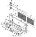
- FIG. 1is an exploded perspective view illustrating a LED sign having a cover comprising a first embodiment of the present invention
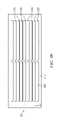
- FIG. 2is a front view of the LED sign cover of FIG. 1 ;
- FIG. 3is a top view of the LED sign cover of FIG. 1 ;
- FIG. 4is a side view of the LED sign cover of FIG. 1 ;
- FIG. 5is an enlargement of the lower portion of FIG. 4 ;
- FIG. 6is an exploded perspective view of a LED sign having a cover comprising a second embodiment of the invention.
- FIG. 7is an exploded perspective view showing the LED sign of FIG. 6 at an earlier stage in its manufacture
- FIG. 8is an exploded perspective view showing the LED sign of FIG. 6 of at a still earlier stage in its manufacture
- FIGS. 9 a and 9 bare front views of the LED sign cover of FIG. 6 ;
- FIG. 10is a top view of the LED sign cover of FIG. 6 ;
- FIG. 11is a side view of the LED sign cover of FIG. 6 .
- the LED sign 20includes a housing 24 which receives and supports a circuit board 26 having an array of light emitting diodes 28 mounted thereon.
- the array of light emitting diodes 28is characterized by a relatively long horizontal dimension and a relatively short vertical dimension.
- Operating power and control signals for the array of light emitting diodes 28are directed to a plurality of electronic components mounted on the reverse side of the circuit board 26 through a pair of cables 30 and 32 which extend from connectors 34 and 36 , respectively, through an aperture 38 formed in the housing 24 .
- the LED sign 20further includes a front plate 40 having a plurality of apertures 42 formed therethrough. Each of the apertures 42 receives, supports, and protects one of the light emitting diodes 28 mounted on the circuit board 26 .
- the front plate 40is secured to the housing 24 by fasteners which extend through apertures 44 formed in tabs 46 extending rearwardly from the front plate 40 and apertures 48 extending through the housing 24 .
- the cover 22 for the LED sign 20is further illustrated in FIGS. 2 , 3 , 4 , and 5 .
- the cover 22is formed from a plate 52 which is preferably formed from stainless steel. Other materials may be utilized in the manufacture of the cover 22 provided that the material selected for the manufacture of the cover 22 is opaque.
- the plate 52has a plurality of apertures 54 formed therein. The function of the apertures 54 is to facilitate viewing the light emitting diodes 42 comprising the LED sign 20 .
- the apertures 54 comprising the cover 22are substantially identical in size and shape. Moreover, the apertures 54 extend substantially parallel to one another. As will be understood by those skilled in the art, other aperture configurations can be utilized in the practice of the invention.
- Each of the apertures 54is fabricated by forming a relatively long first cut line 56 and two relatively short second cut lines 58 in the stainless steel plate 52 .
- the second cut lines 58extend angularly relative to the first cut line 56 from the opposite ends thereof. As illustrated in FIG. 2 , the second cut lines 58 may extend perpendicularly relative to the first cut line 56 , however, angular relationships between the first cut line 56 and the second cut lines 58 may be utilized in the practice of the invention depending upon the requirements of particular applications thereof.
- the first and second cut lines 56 and 58are formed in the stainless steel sheet 52 utilizing a laser cutter. Multiple passes in the laser cutter may be required in order to form cut lines 56 and 58 having adequate width. After the cut lines 56 and 58 are formed, the portion of the stainless steel plate 52 extending between the two second cut lines 58 is bent out of the plane of the plate 52 . A machine tool of the type known as a break is preferably utilized to bend the portion of the stainless steel plate 52 extending between the second cut lines 58 relative to the remainder thereof.
- the function of the apertures 54is to facilitate viewing of the array of light emitting diodes 28 comprising the LED sign 20 .
- the function of the louvers 60 extending adjacent to the apertures 54is to shield light emitting diodes 28 from excessive light which would otherwise denigrate the contrast between the light emitting diodes and the background thereof thereby hindering the ability of visually impaired persons to read the LED sign 20 .
- the louvers 60are further illustrated in FIGS. 4 and 5 . Most of the louvers 60 are located along the upper edge of the corresponding aperture 54 . However, as is indicated in FIG. 5 , a louver 60 may be provided along the lower edge of the lowermost aperture 54 of the cover 22 .
- FIGS. 4 and 5further illustrate the louvers 60 as extending substantially perpendicularly relative to the plane of the stainless steel plate 52 . However, the louvers which are located along the upper edges of the apertures 54 may extend angularly downwardly from the perpendicular orientation illustrated in FIGS. 4 and 5 . If the louvers 60 are bent into an angularly downwardly extending orientation, the extent of downward inclination of the louvers 60 from the perpendicular orientation shown in FIGS. 4 and 5 is typically between about zero degrees and about 10 degrees.
- the LED sign 80having the cover 82 comprising the second embodiment of the invention.
- the LED sign 80includes a housing 83 having a back plate 84 hingedly mounted thereon.
- the back plate 84supports a plurality of electronic components which drive and control the operation of the LED sign 80 .
- Operating power and control signalsare directed to the LED sign 80 through a plurality of cables 86 , 88 , and 90 which extends from a plurality of connectors 92 and 94 to the operating components of the LED sign 80 through an aperture 98 .
- the LED sign 80further includes a printed circuit board 100 which is operatively connected to the electronic components mounted on the back plate 84 of the housing 83 .
- the printed circuit board 100has an array of light emitting diodes mounted on the reverse side thereof.
- the array of light emitting diodesis characterized by relatively long horizontal dimension and a relatively short vertical dimension.
- the housing 83 of the LED sign 80further comprising a front plate 102 .
- the front plate 102has an array of light emitting diode receiving apertures formed therein.
- Each of the apertures 104receives, positions, and protects one of the light emitting diodes mounted on the printed circuit board 100 .
- the array of apertures 104 as illustrated in FIG. 7corresponds identically to the array of light emitting diodes mounted on the printed circuit board 100 .
- the cover 82 for the LED sign 80is further illustrated in FIGS. 9 , 10 , and 11 .
- the cover 82is formed from a plate 112 which is preferably formed from stainless steel. Other materials may be utilized in the manufacture of the cover 82 provided that the material selected for the manufacture of the cover 82 is opaque.
- the plate 112has a plurality of apertures 114 formed therein. The function of the apertures 114 is to facilitate viewing the light emitting diodes comprising the LED sign 80 .
- the apertures 114 comprising the cover 82are substantially identical in size and shape. Moreover, the apertures 114 extend substantially parallel to one another. As will be understood by those skilled in the art, other aperture configurations can be utilized in the practice of the invention.
- Each of the apertures 114is fabricated by forming a relatively long first cut line 116 and two relatively short second cut lines 118 in the stainless steel plate 112 as illustrated in FIG. 9 b .
- the second cut lines 118extend angularly relative to the first cut line 116 from the opposite ends thereof. As illustrated in FIGS. 9 a and 9 b , the second cut lines 118 may extend perpendicularly relative to the first cut line 116 , however, other angular relationships between the first cut line 116 and the second cut lines 118 may be utilized in the practice of the invention depending upon the requirements of particular applications thereof.
- the first and second cut lines 116 and 118are formed in the stainless steel sheet 112 utilizing a laser cutter. Multiple passes in the laser cutter may be required in order to form cut lines 116 and 118 having adequate width. After the cut lines 116 and 118 are formed, the portion of the stainless steel plate 112 extending between the two second cut lines 118 is bent out of the plane of the plate 112 . A machine tool of the type known as a break is preferably utilized to bend the portion of the stainless steel plate 112 extending between the second cut lines 118 relative to the remainder thereof.
- the function of the apertures 114is to facilitate viewing of the array of light emitting diodes comprising the LED sign 80 .
- the function of the louvers 120 extending adjacent to the apertures 114is to shield light emitting diodes from excessive light which would otherwise denigrate the contrast between the light emitting diodes and the background thereof thereby hindering the ability of visually impaired persons to read the LED sign 80 .
- the louvers 120are further illustrated in FIG. 11 .
- the louvers 120are located along the upper edges of the corresponding apertures 114 .
- FIG. 11further illustrate the louver 120 as extending substantially perpendicularly relative to the plane of the stainless steel plate 112 .
- the louvers 120may extend angularly downwardly from the perpendicular orientation illustrated in FIG. 11 . If the louvers 120 are bent into an angularly downwardly extending orientation, the extent of downward inclination of the louvers 120 from the perpendicular orientation shown in FIG. 11 is typically between about zero degrees and about 10 degrees.
Landscapes
- Physics & Mathematics (AREA)
- General Physics & Mathematics (AREA)
- Engineering & Computer Science (AREA)
- Theoretical Computer Science (AREA)
- Illuminated Signs And Luminous Advertising (AREA)
Abstract
Description
Claims (13)
Priority Applications (1)
| Application Number | Priority Date | Filing Date | Title |
|---|---|---|---|
| US10/869,305US7287878B2 (en) | 2003-06-24 | 2004-06-16 | LED sign cover and method of manufacture |
Applications Claiming Priority (2)
| Application Number | Priority Date | Filing Date | Title |
|---|---|---|---|
| US48096503P | 2003-06-24 | 2003-06-24 | |
| US10/869,305US7287878B2 (en) | 2003-06-24 | 2004-06-16 | LED sign cover and method of manufacture |
Publications (2)
| Publication Number | Publication Date |
|---|---|
| US20040264206A1 US20040264206A1 (en) | 2004-12-30 |
| US7287878B2true US7287878B2 (en) | 2007-10-30 |
Family
ID=33544476
Family Applications (1)
| Application Number | Title | Priority Date | Filing Date |
|---|---|---|---|
| US10/869,305Expired - LifetimeUS7287878B2 (en) | 2003-06-24 | 2004-06-16 | LED sign cover and method of manufacture |
Country Status (1)
| Country | Link |
|---|---|
| US (1) | US7287878B2 (en) |
Cited By (15)
| Publication number | Priority date | Publication date | Assignee | Title |
|---|---|---|---|---|
| US20080141570A1 (en)* | 2006-10-30 | 2008-06-19 | Daktronics, Inc. | Thermoplastic elastomer protective louver covering for use with an electronic display module |
| US20090241941A1 (en)* | 2006-06-30 | 2009-10-01 | Michael Hermann | Partially transparent sun collector having a sun protection function |
| US7936564B1 (en)* | 2009-11-17 | 2011-05-03 | Young Electric Sign Company | Mobile displays and related methods |
| US20110199760A1 (en)* | 2010-02-18 | 2011-08-18 | Koninklijke Philips Electronics N.V. | Lighting fixture having a louvered light shield |
| US8824125B1 (en) | 2013-03-16 | 2014-09-02 | ADTI Media, LLC | Modular installation and conversion kit for electronic sign structure and method of using same |
| US8929083B2 (en) | 2013-03-16 | 2015-01-06 | ADIT Media, LLC | Compound structural frame and method of using same for efficient retrofitting |
| US9047791B2 (en) | 2013-03-16 | 2015-06-02 | Adti Media, Llc. | Sign construction with sectional sign assemblies and installation kit and method of using same |
| US9666105B2 (en) | 2013-03-16 | 2017-05-30 | ADTI Media, LLC | Sign construction with modular wire harness arrangements and methods of using same for backside to frontside power and data distribution schemes |
| US9761157B2 (en) | 2013-03-16 | 2017-09-12 | Adti Media Llc | Customized sectional sign assembly kit and method of using kit for construction and installation of same |
| US9852666B2 (en) | 2013-03-16 | 2017-12-26 | Adti Media Llc | Full height sectional sign assembly and installation kit and method of using same |
| US10061553B2 (en) | 2013-12-31 | 2018-08-28 | Ultravision Technologies, Llc | Power and data communication arrangement between panels |
| US10248372B2 (en) | 2013-12-31 | 2019-04-02 | Ultravision Technologies, Llc | Modular display panels |
| US10373535B2 (en) | 2013-12-31 | 2019-08-06 | Ultravision Technologies, Llc | Modular display panel |
| US10706770B2 (en) | 2014-07-16 | 2020-07-07 | Ultravision Technologies, Llc | Display system having module display panel with circuitry for bidirectional communication |
| US10891881B2 (en) | 2012-07-30 | 2021-01-12 | Ultravision Technologies, Llc | Lighting assembly with LEDs and optical elements |
Families Citing this family (7)
| Publication number | Priority date | Publication date | Assignee | Title |
|---|---|---|---|---|
| USD578971S1 (en)* | 2007-03-09 | 2008-10-21 | Chainzone Technology (Foshan) Co., Ltd. | Light emitting diode light display cabinet |
| US20140153241A1 (en)* | 2012-12-01 | 2014-06-05 | Lsi Industries, Inc. | Display board and display board components |
| US9109769B2 (en)* | 2013-03-15 | 2015-08-18 | James M. Lee | Portable cordless multipurpose lighting system |
| JP6107564B2 (en)* | 2013-09-20 | 2017-04-05 | 日亜化学工業株式会社 | Manufacturing method of display device |
| GB201510302D0 (en)* | 2015-06-12 | 2015-07-29 | 13 Digital Ltd | Vehicle with advertising screen |
| ES2809563T3 (en)* | 2016-07-11 | 2021-03-04 | Screen Experts Gmbh | Module with a plurality of LEDs and video card |
| KR102087431B1 (en)* | 2019-09-20 | 2020-03-11 | 주식회사 아하정보통신 | Waterproof cover and display device including the same |
Citations (19)
| Publication number | Priority date | Publication date | Assignee | Title |
|---|---|---|---|---|
| US1363805A (en)* | 1917-10-11 | 1920-12-28 | Abraham L Morrison | Lens |
| US2182957A (en)* | 1939-03-18 | 1939-12-12 | Blanck Joseph Thomas | Game |
| US2540389A (en)* | 1946-02-21 | 1951-02-06 | Elwood Wiles | Signal light ray director |
| US2701298A (en)* | 1952-05-14 | 1955-02-01 | Nicholas M Michailovsky | Driving light shield |
| US3083630A (en)* | 1960-11-07 | 1963-04-02 | Bernard E Thaxton | Window mounted ventilator |
| US3604922A (en)* | 1968-08-20 | 1971-09-14 | John F Steel | Automobile headlamp |
| US3745355A (en)* | 1971-12-14 | 1973-07-10 | J Seamon | Label holder for automatic car identification system |
| US4232483A (en)* | 1978-09-21 | 1980-11-11 | Robert Lockshin | Hinged louvered window shade device |
| US4368605A (en)* | 1980-09-22 | 1983-01-18 | Ulrich Everette R | Automobile louver assemblage |
| US5140495A (en)* | 1989-06-05 | 1992-08-18 | Varvel Joseph H | Apparatus and method for prevention of pooling in carpets and the like |
| US5299111A (en)* | 1990-09-11 | 1994-03-29 | Parduhn A Philip | Device for directing a beam of light |
| US5390092A (en)* | 1994-06-01 | 1995-02-14 | Formosa Industrial Computing Inc. | Receptacle apparatus for light emitting diodes |
| US5949581A (en)* | 1997-08-12 | 1999-09-07 | Daktronics, Inc. | Display system |
| US5950753A (en)* | 1997-07-14 | 1999-09-14 | Chrysler Corporation | Vehicle hood louvers water management system |
| US6095668A (en)* | 1996-06-19 | 2000-08-01 | Radiant Imaging, Inc. | Incandescent visual display system having a shaped reflector |
| US6170566B1 (en)* | 1999-12-22 | 2001-01-09 | Visteon Global Technologies, Inc. | High performance louvered fin for a heat exchanger |
| US6550937B2 (en)* | 2001-05-09 | 2003-04-22 | Philip John Glass | Louvered screen to control light |
| US6626560B1 (en)* | 2000-11-22 | 2003-09-30 | Ronald N. Caferro | Lighting louver |
| US20040148829A1 (en)* | 2003-02-03 | 2004-08-05 | Gray James Earl | Display device with rail support |
- 2004
- 2004-06-16USUS10/869,305patent/US7287878B2/ennot_activeExpired - Lifetime
Patent Citations (19)
| Publication number | Priority date | Publication date | Assignee | Title |
|---|---|---|---|---|
| US1363805A (en)* | 1917-10-11 | 1920-12-28 | Abraham L Morrison | Lens |
| US2182957A (en)* | 1939-03-18 | 1939-12-12 | Blanck Joseph Thomas | Game |
| US2540389A (en)* | 1946-02-21 | 1951-02-06 | Elwood Wiles | Signal light ray director |
| US2701298A (en)* | 1952-05-14 | 1955-02-01 | Nicholas M Michailovsky | Driving light shield |
| US3083630A (en)* | 1960-11-07 | 1963-04-02 | Bernard E Thaxton | Window mounted ventilator |
| US3604922A (en)* | 1968-08-20 | 1971-09-14 | John F Steel | Automobile headlamp |
| US3745355A (en)* | 1971-12-14 | 1973-07-10 | J Seamon | Label holder for automatic car identification system |
| US4232483A (en)* | 1978-09-21 | 1980-11-11 | Robert Lockshin | Hinged louvered window shade device |
| US4368605A (en)* | 1980-09-22 | 1983-01-18 | Ulrich Everette R | Automobile louver assemblage |
| US5140495A (en)* | 1989-06-05 | 1992-08-18 | Varvel Joseph H | Apparatus and method for prevention of pooling in carpets and the like |
| US5299111A (en)* | 1990-09-11 | 1994-03-29 | Parduhn A Philip | Device for directing a beam of light |
| US5390092A (en)* | 1994-06-01 | 1995-02-14 | Formosa Industrial Computing Inc. | Receptacle apparatus for light emitting diodes |
| US6095668A (en)* | 1996-06-19 | 2000-08-01 | Radiant Imaging, Inc. | Incandescent visual display system having a shaped reflector |
| US5950753A (en)* | 1997-07-14 | 1999-09-14 | Chrysler Corporation | Vehicle hood louvers water management system |
| US5949581A (en)* | 1997-08-12 | 1999-09-07 | Daktronics, Inc. | Display system |
| US6170566B1 (en)* | 1999-12-22 | 2001-01-09 | Visteon Global Technologies, Inc. | High performance louvered fin for a heat exchanger |
| US6626560B1 (en)* | 2000-11-22 | 2003-09-30 | Ronald N. Caferro | Lighting louver |
| US6550937B2 (en)* | 2001-05-09 | 2003-04-22 | Philip John Glass | Louvered screen to control light |
| US20040148829A1 (en)* | 2003-02-03 | 2004-08-05 | Gray James Earl | Display device with rail support |
Cited By (26)
| Publication number | Priority date | Publication date | Assignee | Title |
|---|---|---|---|---|
| US20090241941A1 (en)* | 2006-06-30 | 2009-10-01 | Michael Hermann | Partially transparent sun collector having a sun protection function |
| US8607781B2 (en)* | 2006-06-30 | 2013-12-17 | Fraunhofer-Gesellschaft Zur Foerderung Der Angewandten Forschung E.V. | Partially transparent sun collector having a sun protection function |
| US20080141570A1 (en)* | 2006-10-30 | 2008-06-19 | Daktronics, Inc. | Thermoplastic elastomer protective louver covering for use with an electronic display module |
| US7936564B1 (en)* | 2009-11-17 | 2011-05-03 | Young Electric Sign Company | Mobile displays and related methods |
| US20110116232A1 (en)* | 2009-11-17 | 2011-05-19 | Young Electric Sign Company | Mobile displays and related methods |
| US20110199760A1 (en)* | 2010-02-18 | 2011-08-18 | Koninklijke Philips Electronics N.V. | Lighting fixture having a louvered light shield |
| US8608337B2 (en) | 2010-02-18 | 2013-12-17 | Koninklijke Philips N.V. | Lighting fixture having a louvered light shield |
| US10891881B2 (en) | 2012-07-30 | 2021-01-12 | Ultravision Technologies, Llc | Lighting assembly with LEDs and optical elements |
| US9761157B2 (en) | 2013-03-16 | 2017-09-12 | Adti Media Llc | Customized sectional sign assembly kit and method of using kit for construction and installation of same |
| US9047791B2 (en) | 2013-03-16 | 2015-06-02 | Adti Media, Llc. | Sign construction with sectional sign assemblies and installation kit and method of using same |
| US9536457B2 (en) | 2013-03-16 | 2017-01-03 | Adti Media Llc | Installation kit and method of using same for sign construction with sectional sign assemblies |
| US9666105B2 (en) | 2013-03-16 | 2017-05-30 | ADTI Media, LLC | Sign construction with modular wire harness arrangements and methods of using same for backside to frontside power and data distribution schemes |
| US8929083B2 (en) | 2013-03-16 | 2015-01-06 | ADIT Media, LLC | Compound structural frame and method of using same for efficient retrofitting |
| US9852666B2 (en) | 2013-03-16 | 2017-12-26 | Adti Media Llc | Full height sectional sign assembly and installation kit and method of using same |
| US8824125B1 (en) | 2013-03-16 | 2014-09-02 | ADTI Media, LLC | Modular installation and conversion kit for electronic sign structure and method of using same |
| US10192468B2 (en) | 2013-03-16 | 2019-01-29 | ADTI Media, LLC | Sign construction with modular installation and conversion kit for electronic sign structure and method of using same |
| US10210778B2 (en) | 2013-03-16 | 2019-02-19 | Adti Media Llc | Sign construction with sectional sign assemblies and installation kit and method of using same |
| US10248372B2 (en) | 2013-12-31 | 2019-04-02 | Ultravision Technologies, Llc | Modular display panels |
| US10373535B2 (en) | 2013-12-31 | 2019-08-06 | Ultravision Technologies, Llc | Modular display panel |
| US10380925B2 (en) | 2013-12-31 | 2019-08-13 | Ultravision Technologies, Llc | Modular display panel |
| US10410552B2 (en) | 2013-12-31 | 2019-09-10 | Ultravision Technologies, Llc | Modular display panel |
| US10540917B2 (en) | 2013-12-31 | 2020-01-21 | Ultravision Technologies, Llc | Modular display panel |
| US10741107B2 (en) | 2013-12-31 | 2020-08-11 | Ultravision Technologies, Llc | Modular display panel |
| US10871932B2 (en) | 2013-12-31 | 2020-12-22 | Ultravision Technologies, Llc | Modular display panels |
| US10061553B2 (en) | 2013-12-31 | 2018-08-28 | Ultravision Technologies, Llc | Power and data communication arrangement between panels |
| US10706770B2 (en) | 2014-07-16 | 2020-07-07 | Ultravision Technologies, Llc | Display system having module display panel with circuitry for bidirectional communication |
Also Published As
| Publication number | Publication date |
|---|---|
| US20040264206A1 (en) | 2004-12-30 |
Similar Documents
| Publication | Publication Date | Title |
|---|---|---|
| US7287878B2 (en) | LED sign cover and method of manufacture | |
| US7362046B2 (en) | Partial overlapping display tiles of organic light emitting device | |
| US10410550B2 (en) | Local light-emitting road sign board apparatus | |
| EP0677833A2 (en) | High-luminous-pattern display apparatus | |
| KR20010049704A (en) | Display units | |
| CN101140405B (en) | Projection device | |
| DE69223060T2 (en) | INFORMATION DISPLAY DEVICE | |
| WO2007058955A2 (en) | Hooded face plate for a message and display sign | |
| US20120057369A1 (en) | Light emitting structure for backlighted sign | |
| CN219606479U (en) | LED flexible screen with adjustable inner and outer radians | |
| WO2004042690A1 (en) | Display unit with light emitting diode (led) for display billboards and method thereof | |
| US20050246927A1 (en) | Electronic sign | |
| US20050062396A1 (en) | Multi-hooded pixel | |
| US12007560B2 (en) | Head-up display device having light sources arranged in rows supplied with different currents | |
| WO1985004506A1 (en) | Indicating device | |
| US4639724A (en) | Graphic display | |
| US10078975B2 (en) | Highway variable message sign with apertures | |
| JPH08111103A (en) | Display device | |
| CN214152303U (en) | Electronic guideboard | |
| KR200347655Y1 (en) | Sunscreen for Electric Signboard | |
| JP2000328523A (en) | Translucent traffic sign | |
| KR101724615B1 (en) | A LED Display Apparatus Having a Shutter Unit | |
| JP2005084153A (en) | Display device | |
| KR102616507B1 (en) | Inner bumper projection system for automabiles using unit solid state surface light source and meta-mirror(multi-mirror cells) | |
| JPH0720703Y2 (en) | Self-luminous signboard |
Legal Events
| Date | Code | Title | Description |
|---|---|---|---|
| AS | Assignment | Owner name:DIGITAL RECORDERS, INC., TEXAS Free format text:ASSIGNMENT OF ASSIGNORS INTEREST;ASSIGNOR:MILLER, WILLIAM H.;REEL/FRAME:015063/0008 Effective date:20040706 | |
| AS | Assignment | Owner name:LAURUS MASTER FUND, LTD., NEW YORK Free format text:SECURITY AGREEMENT;ASSIGNORS:DIGITAL RECORDERS, INC.;DIGITAL AUDIO CORPORATION;TWIN VISION OF NORTH AMERICA, INC.;REEL/FRAME:018901/0773 Effective date:20060315 | |
| STCF | Information on status: patent grant | Free format text:PATENTED CASE | |
| AS | Assignment | Owner name:BHC INTERIM FUNDING III, L.P., NEW YORK Free format text:SECURITY AGREEMENT;ASSIGNOR:DIGITAL RECORDERS, INC.;REEL/FRAME:021172/0786 Effective date:20080630 | |
| AS | Assignment | Owner name:PNC BANK, NATIONAL ASSOCIATION, NEW JERSEY Free format text:SECURITY AGREEMENT;ASSIGNOR:DIGITAL RECORDERS, INC.;REEL/FRAME:021194/0283 Effective date:20080630 | |
| AS | Assignment | Owner name:DIGITAL RECORDERS, INC., TEXAS Free format text:RELEASE BY SECURED PARTY;ASSIGNOR:LAURUS MASTER FUND, LTD.;REEL/FRAME:021217/0383 Effective date:20080630 | |
| FEPP | Fee payment procedure | Free format text:PAT HOLDER CLAIMS SMALL ENTITY STATUS, ENTITY STATUS SET TO SMALL (ORIGINAL EVENT CODE: LTOS); ENTITY STATUS OF PATENT OWNER: SMALL ENTITY | |
| FPAY | Fee payment | Year of fee payment:4 | |
| AS | Assignment | Owner name:DRI AGENT INC., NEW YORK Free format text:ASSIGNMENT OF GRANT OF SECURITY INTEREST IN PATENTS;ASSIGNOR:PNC BANK, NATIONAL ASSOCIATION;REEL/FRAME:027727/0891 Effective date:20120216 | |
| AS | Assignment | Owner name:SIEMENS FINANCIAL SERVICES, INC., AS COLLATERAL AG Free format text:LIEN;ASSIGNOR:DRI NEWCO LLC;REEL/FRAME:028712/0586 Effective date:20120711 | |
| AS | Assignment | Owner name:LUMINATOR HOLDING L.P., TEXAS Free format text:ASSIGNMENT OF ASSIGNORS INTEREST;ASSIGNOR:DRI NEWCO LLC;REEL/FRAME:029889/0775 Effective date:20130204 | |
| AS | Assignment | Owner name:DIGITAL RECORDERS, INC., TEXAS Free format text:BANKRUPTCY COURT ORDER RELEASING ALL LIENS, INCLUDING THE SECURITY INTEREST RECORDED AT REEL/FRAME 021194/0283;ASSIGNOR:DRI AGENT INC. (SUCCESSOR BY ASSIGNMENT (SEE R/F 027727/0891) TO PNC BANK, NATIONAL ASSOCIATION);REEL/FRAME:032590/0835 Effective date:20120626 Owner name:DIGITAL RECORDERS, INC., TEXAS Free format text:BANKRUPTCY COURT ORDER RELEASING ALL LIENS, INCLUDING THE SECURITY INTEREST RECORDED AT REEL/FRAME 021172/0786;ASSIGNOR:BHC INTERIM FUNDING III, L.P.;REEL/FRAME:032642/0207 Effective date:20120626 | |
| AS | Assignment | Owner name:GENERAL ELECTRIC CAPITAL CORPORATION, AS US AGENT, Free format text:SECURITY INTEREST;ASSIGNOR:LUMINATOR HOLDING L.P.;REEL/FRAME:032619/0814 Effective date:20140404 | |
| AS | Assignment | Owner name:HSBC BANK USA, N.A., NEW YORK Free format text:SECURITY AGREEMENT;ASSIGNOR:CLEVER DEVICES LTD.;REEL/FRAME:032820/0558 Effective date:20130731 | |
| AS | Assignment | Owner name:DRI NEWCO LLC, TEXAS Free format text:RELEASE OF SECURITY INTEREST RECORDED AT REEL/FRAME 028712/0586;ASSIGNOR:SIEMENS FINANCIAL SERVICES, INC.;REEL/FRAME:032910/0116 Effective date:20140404 | |
| AS | Assignment | Owner name:AMERICAN CAPITAL, LTD., MARYLAND Free format text:SECURITY INTEREST;ASSIGNOR:LUMINATOR HOLDING L.P.;REEL/FRAME:033053/0330 Effective date:20140404 | |
| FPAY | Fee payment | Year of fee payment:8 | |
| AS | Assignment | Owner name:ANTARES CAPITAL LP, AS SUCCESSOR AGENT, ILLINOIS Free format text:ASSIGNMENT OF INTELLECTUAL PROPERTY SECURITY AGREEMENT;ASSIGNOR:GENERAL ELECTRIC CAPITAL CORPORATION, AS RETIRING AGENT;REEL/FRAME:036538/0346 Effective date:20150821 | |
| AS | Assignment | Owner name:LUMINATOR HOLDING L.P., TEXAS Free format text:RELEASE OF SECURITY INTEREST IN INTELLECTUAL PROPERTY COLLATERAL;ASSIGNOR:ANTARES CAPITAL LP, AS US AGENT;REEL/FRAME:039646/0128 Effective date:20160809 Owner name:ELAVON FINANCIAL SERVICES DAC, U.K. BRANCH AS SECU Free format text:PATENT SECURITY AGREEMENT;ASSIGNOR:LUMINATOR HOLDING L.P.;REEL/FRAME:039644/0123 Effective date:20160809 Owner name:LUMINATOR HOLDING L.P., TEXAS Free format text:RELEASE OF SECURITY INTEREST RECORDED AT REEL/FRAME 033053/0330;ASSIGNOR:AMERICAN CAPITAL, LTD.;REEL/FRAME:039646/0118 Effective date:20160809 | |
| MAFP | Maintenance fee payment | Free format text:PAYMENT OF MAINTENANCE FEE, 12TH YR, SMALL ENTITY (ORIGINAL EVENT CODE: M2553); ENTITY STATUS OF PATENT OWNER: SMALL ENTITY Year of fee payment:12 | |
| AS | Assignment | Owner name:CLEVER DEVICES LTD., NEW YORK Free format text:RELEASE BY SECURED PARTY;ASSIGNOR:HSBC BANK USA, N.A.;REEL/FRAME:067733/0611 Effective date:20240612 Owner name:CLEVER DEVICES LTD., NEW YORK Free format text:RELEASE BY SECURED PARTY;ASSIGNOR:HSBC BANK USA, N.A.;REEL/FRAME:067732/0264 Effective date:20240612 |