US7287596B2 - Method and apparatus for stimulating hydrocarbon wells - Google Patents
Method and apparatus for stimulating hydrocarbon wellsDownload PDFInfo
- Publication number
- US7287596B2 US7287596B2US11/010,072US1007204AUS7287596B2US 7287596 B2US7287596 B2US 7287596B2US 1007204 AUS1007204 AUS 1007204AUS 7287596 B2US7287596 B2US 7287596B2
- Authority
- US
- United States
- Prior art keywords
- flapper valve
- well
- sleeve
- valve member
- flapper
- Prior art date
- Legal status (The legal status is an assumption and is not a legal conclusion. Google has not performed a legal analysis and makes no representation as to the accuracy of the status listed.)
- Expired - Fee Related, expires
Links
- 229930195733hydrocarbonNatural products0.000titleclaimsabstractdescription19
- 239000004215Carbon black (E152)Substances0.000titleclaimsabstractdescription17
- 150000002430hydrocarbonsChemical class0.000titledescription11
- 238000000034methodMethods0.000titledescription10
- 230000004936stimulating effectEffects0.000titledescription4
- 230000000712assemblyEffects0.000claimsabstractdescription11
- 238000000429assemblyMethods0.000claimsabstractdescription11
- 125000001183hydrocarbyl groupChemical group0.000claimsabstract8
- 230000015572biosynthetic processEffects0.000claimsdescription21
- 239000000463materialSubstances0.000claimsdescription9
- 238000007789sealingMethods0.000claimsdescription9
- 239000002253acidSubstances0.000claimsdescription4
- XAGFODPZIPBFFR-UHFFFAOYSA-NaluminiumChemical compound[Al]XAGFODPZIPBFFR-UHFFFAOYSA-N0.000claimsdescription3
- 229910052782aluminiumInorganic materials0.000claimsdescription3
- 238000011282treatmentMethods0.000claimsdescription3
- 229910001018Cast ironInorganic materials0.000claimsdescription2
- 239000000919ceramicSubstances0.000claimsdescription2
- 239000002195soluble materialSubstances0.000claimsdescription2
- 230000000295complement effectEffects0.000claims1
- 230000000149penetrating effectEffects0.000claims1
- 238000004519manufacturing processMethods0.000abstractdescription21
- 238000005755formation reactionMethods0.000description19
- 239000007789gasSubstances0.000description9
- 238000004140cleaningMethods0.000description6
- 238000005553drillingMethods0.000description6
- 239000004568cementSubstances0.000description5
- 230000000638stimulationEffects0.000description5
- 230000035699permeabilityEffects0.000description4
- 239000002002slurrySubstances0.000description4
- 230000008569processEffects0.000description3
- 230000008901benefitEffects0.000description2
- 230000000903blocking effectEffects0.000description2
- 238000004891communicationMethods0.000description2
- 230000008878couplingEffects0.000description2
- 238000010168coupling processMethods0.000description2
- 238000005859coupling reactionMethods0.000description2
- 239000012530fluidSubstances0.000description2
- 230000007246mechanismEffects0.000description2
- VNWKTOKETHGBQD-UHFFFAOYSA-NmethaneChemical compoundCVNWKTOKETHGBQD-UHFFFAOYSA-N0.000description2
- 239000004576sandSubstances0.000description2
- 241000169624Casearia sylvestrisSpecies0.000description1
- 235000015076Shorea robustaNutrition0.000description1
- 244000166071Shorea robustaSpecies0.000description1
- 229910045601alloyInorganic materials0.000description1
- 239000000956alloySubstances0.000description1
- 239000006227byproductSubstances0.000description1
- 230000003247decreasing effectEffects0.000description1
- 239000000706filtrateSubstances0.000description1
- 230000009969flowable effectEffects0.000description1
- 230000005484gravityEffects0.000description1
- 230000006872improvementEffects0.000description1
- 238000002347injectionMethods0.000description1
- 239000007924injectionSubstances0.000description1
- 239000007788liquidSubstances0.000description1
- 239000003345natural gasSubstances0.000description1
- 238000002360preparation methodMethods0.000description1
- 238000005086pumpingMethods0.000description1
- 239000011435rockSubstances0.000description1
- 230000003313weakening effectEffects0.000description1
Images

Classifications
- E—FIXED CONSTRUCTIONS
- E21—EARTH OR ROCK DRILLING; MINING
- E21B—EARTH OR ROCK DRILLING; OBTAINING OIL, GAS, WATER, SOLUBLE OR MELTABLE MATERIALS OR A SLURRY OF MINERALS FROM WELLS
- E21B43/00—Methods or apparatus for obtaining oil, gas, water, soluble or meltable materials or a slurry of minerals from wells
- E21B43/14—Obtaining from a multiple-zone well
- E—FIXED CONSTRUCTIONS
- E21—EARTH OR ROCK DRILLING; MINING
- E21B—EARTH OR ROCK DRILLING; OBTAINING OIL, GAS, WATER, SOLUBLE OR MELTABLE MATERIALS OR A SLURRY OF MINERALS FROM WELLS
- E21B34/00—Valve arrangements for boreholes or wells
- E21B34/06—Valve arrangements for boreholes or wells in wells
- E—FIXED CONSTRUCTIONS
- E21—EARTH OR ROCK DRILLING; MINING
- E21B—EARTH OR ROCK DRILLING; OBTAINING OIL, GAS, WATER, SOLUBLE OR MELTABLE MATERIALS OR A SLURRY OF MINERALS FROM WELLS
- E21B2200/00—Special features related to earth drilling for obtaining oil, gas or water
- E21B2200/05—Flapper valves
Definitions
- This inventionrelates to a method and apparatus for completing hydrocarbon wells and more particularly to a technique for stimulating multiple zones in a single well and then cleaning up the well in preparation for production.
- one or more check valvesare provided in a casing string cemented in the earth.
- sequential stimulation operations in the wellsuch as fracing, acidizing or otherwise treating a series of spaced hydrocarbon bearing zones
- a lowermost zonein the case of a vertical well, or a most distant zone, in the case of a horizontal well, is perforated and treated.
- the check valveis then manipulated or installed to isolate the lower zone by preventing downward flow in the well and allowing upward flow.
- the preferred flapper valvesare run on the casing string and cemented in the earth.
- the flapper valvesare initially held in a retracted or stowed position providing an opening therethrough the same size as the internal diameter of the casing string, allowing the expeditious circulation of cement, frac slurry or other materials down the casing string.
- the flapper valveis later manipulated to move to an operative position allowing upward flow in the casing string and preventing downward flow to isolate a lower stimulated zone and thereby allowing stimulation of an upper zone.
- An upper zone in the case of a vertical well or zone less distant from the surface in the case of a horizontal wellis then perforated and treated.
- a flapper valve above the second treated zoneis manipulated to prevent pumping into the second zone. This process is repeated until all of the desired zones have been treated.
- the wellis then put onto production, either by drilling out or breaking the check valves and opening the well at the surface, or simply by opening the well to the atmosphere or to production equipment at the surface.
- the pressure differential across the check valveis sufficient to open it and allow the treated zones to produce formation contents, thereby cleaning up the well and allowing it to be put on production.
- Even if debris is on top of the check valvethere is usually enough pressure differential to lift the valve member slightly, thereby allowing hydrocarbons from below to fluidize the debris above the valve and thereby allow it to open, whereupon the fluidized debris will be produced at the surface.
- the preferred flapper valvesare preferably made of a material which is readily disintegrated, e.g. it may be frangible so it is easily drilled or broken or may be digestible, such as acid soluble.
- the wellis put onto production after multiple sequential stimulation jobs simply by opening the well at the surface and allowing the flapper valves to open, allowing upward flow in the well.
- debris above one more flapper valveswill have to be cleaned out and the flapper valve drilled out or broken.
- a coiled tubing unitmay be used to drill out or break a flapper valve of this invention, a much less expensive alternative is available.
- the flapper valveIf there is debris on top of the flapper valve, it may be bailed out using a simple slickline unit with a bailer on the bottom of the wireline. If, after bailing, the flapper valve will not open, it may be broken with a sinker bar or other impact device dropped or run in the well with a slickline. Because the flapper valves are full opening, working below one of the valves is easily done because necessary tools pass through the valved opening.
- a further object of this inventionis to provide an improved valve for use in a vertical or horizontal well to prevent downward flow in the well.
- Another object of this inventionis to provide an improved method of stimulating multiple zones in a horizontal or vertical well.
- FIG. 1is a cross-sectional view of a vertical well extending into the earth
- FIG. 2is a cross-sectional view of a horizontal or deviated well in the earth
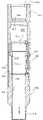
- FIG. 3is an enlarged cross-sectional view of a flapper valve assembly of this invention, illustrating the flapper valve in a stowed or retracted position;
- FIG. 4is a view similar to FIG. 3 , illustrating the flapper valve in an operative position blocking flow downwardly into a well;
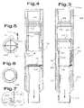
- FIG. 5is an exploded top view of the flapper valve member, pivot pin and spring of this invention.
- FIG. 6is a bottom view of the flapper valve member of FIG. 5 ;
- FIG. 7is a partial enlarged cross-sectional view of the valve seat of FIG. 3 .
- a vertical hydrocarbon producing well 10comprising a bore hole 12 extending from a surface location through the earth to penetrate a series of hydrocarbon bearing intervals or formations 14 , 16 , 18 , 20 .
- a casing string 22comprises a series of pipe joints 24 having a threaded coupling 26 connecting adjacent joints 24 together.
- the casing string 22is permanently placed in the bore hole 12 in any suitable manner, as by conventional cementing to provide a cement sheath 28 preventing communication between adjacent zones.
- Flapper valve assembliescan be positioned in the casing string 22 at locations between the hydrocarbon bearing intervals 14 , 16 , 18 for the purpose Of isolating any lower zone from zones above it so the tipper zone can be stimulated without affecting, or being affected by, the lower zone.
- a flapper valve assembly 30is placed above every zone, except the uppermost zone, to be stimulated in order to isolate the zone immediately below the flapper valve assembly 30 .
- a shiftable sleevemay be provided in the casing string 22 to provide access to the zone 14 .
- the lowermost zone 14is perforated with suitable perforating equipment to produce passages or perforations 32 communicating between the formation 14 and the interior of the casing string 22 .
- the formation 14is then stimulated in any suitable manner, such as by the injection of acid or more typically by fracing in which a proppant laden slurry is pumped through the casing string 22 and perforations 32 to create a fraced area 34 in the formation 14 .
- the fraced area 34may extend many hundreds of feet away from the casing string 22 to produce a high permeability path from the formation 14 to the well 10 .
- the lowermost flapper valve assembly 30is then manipulated to prevent downward flow in the casing string 22 and allowing upward flow. This isolates the zone 14 and allows the next adjacent interval 16 to be perforated and stimulated, typically but not necessarily by fracing.
- the flapper valve assembly 30 above the interval 16is manipulated to isolate the interval 16 and allow the zone 18 to be perforated and treated if necessary.
- the flapper valve assembly 30 above the interval 18is manipulated to isolate the interval 18 and allow the interval 20 to be perforated and stimulated. It will accordingly be seen that any number of intervals may be selectively perforated and stimulated by the use of this invention.
- the well 10is initially produced in order to clean up the well, i.e. produce any frac liquid or flowable proppant, produce any mud filtrate or other by-products of the drilling or completion operation from adjacent the well bore 12 and the like. Initially, this is attempted simply by opening the well 10 to the atmosphere or to surface production equipment (not shown) by opening one or more valves 38 . If there is no debris on top of the flapper valve members 36 , the pressure differential across the valve members causes the members to open thereby allowing upward flow of formation contents to the surface. The well 10 is accordingly put on production without any further substantial cost relating to cleaning up the well. This is in contrast to the current practice of drilling out bridge plugs with a coiled tubing unit which is a costly and not riskless endeavor.
- the pressure differential across the flapper valve members 36is sufficient to partly open the valve members 36 allowing formation contents from below any particular flapper valve assembly to fluidize the debris and flow it to the surface.
- the well 10is accordingly put on production without any further substantial cost relating to cleaning up the well.
- the debrismust be removed. This may be accomplished in a variety of ways, the simplest and least expensive of which is to rig up a wireline unit and bail out enough of the debris to allow the flapper valve member 36 to open. If the flapper valve member 36 won't open, it may be broken by placing a sinker bar on the end of the wireline and dropping the sinker bar on the closed flapper valve member 36 . Because the flapper valve member 36 is preferably made of a frangible material, the member 36 will shatter thereby permanently opening the flapper valve assembly 30 . In the alternative, the valve member 36 may be digestible, e.g.
- flapper valve assembly 30is made of an acid soluble material, such as aluminum or its alloys, so the member 36 may be chemically digested rather than mechanically broken.
- An important feature of the flapper valve assembly 30is that it is full opening, by which is meant that the internal passage through the assembly 30 is at least approximately the same diameter, or cross-sectional area, of the pipe joints 24 . This allows operations below one or more of the flapper valve assemblies 30 because anything that will pass through the pipe joints 24 will pass through the flapper valve assembliea 30 .
- FIG. 2operation of this invention in a horizontal leg 40 of a deviated well 42 is illustrated.
- a bore hole 44is drilled from a surface location through the earth and deviated to pass for a long distance, e.g. more-or-less horizontally, into a hydrocarbon bearing formation 46 .
- a casing string 48is cemented in the well bore 44 and includes a series of pipe joints 50 connected by threaded couplings or collars 52 and a series of spaced apart flapper valve assemblies 54 , which are conveniently identical to the flapper valve assemblies 30 and will be more fully described hereinafter.
- the flapper valve assemblies 54are spaced apart by a distance generally equal to the desired distance between stimulated zones in the formation 46 . For example, it is common to frac horizontal wells at 100-300′ intervals along the length of the casing string 22 so the flow path from low permeability rock to a high permeability fraced area is decreased significantly. In any event, the most distant flapper valve assembly 54 is spaced between the most distant intended fraced area 56 and the next adjacent intended frac area 58 . Additional flapper valve assemblies 54 are placed between adjacent intended frac areas 58 , 60 , 62 in order to isolate the next zone to be stimulated from affecting any more distant fraced zone or being affected by, the more distant zone. It will be recognized that the most distant zone in a horizontal well is analogous to the deepest zone in a vertical well.
- the most distant zone 56is can be perforated with suitable perforating equipment to produce passages or perforations 64 communicating between the formation 46 and the interior of the casing string 48 .
- the formation 46is then stimulated in any suitable manner, typically by fracing in which a proppant laden slurry is pumped through the casing string 48 and perforations 64 to create a fraced area in the intended zone 56 of the formation 46 .
- the fraced areamay extend many hundreds of feet away from the casing string 48 to produce a high permeability path from the formation 48 to the well 42 .
- the most distant flapper valve assembly 54can be manipulated to allows flapper valve member to move to an operative position preventing downward flow in the casing string 48 and allowing upward flow. This isolates the zone 56 and allows the next adjacent interval 58 to be perforated and stimulated, typically but not necessarily by fraying.
- the flapper valve assembly above the interval 58which is more accurately described as nearer the surface or well head 66 , can be manipulated to isolate the interval 58 and allow the Zone 60 to be perforated and treated.
- the flapper valve assembly above the interval 60is manipulated to isolate the interval 60 and allow the interval 62 to be perforated and stimulated. It will accordingly be seen that any-number of intervals may be selectively perforated and stimulated in a horizontal well by the use of this invention.
- the well 42can be produced to clean up the well. Initially, this is attempted simply by opening the well 42 to the atmosphere or to surface production equipment (not shown) by opening one or more valves at the well head 66 . If there is no debris on top of the flapper valve members, the pressure differential across the valve members causes the members to open thereby allowing flow of formation contents to the surface. The well 42 is accordingly put on production without any further substantial cost relating to cleaning up the well. This is in contrast to the current practice of drilling out bridge plugs with a coiled tubing unit which is a costly and risky endeavor.
- the pressure differential across the flapper valve membersis sufficient to partly open the valve members allowing formation contents from below any particular flapper valve assembly to fluidize the debris and flow it to the surface.
- the well 42is accordingly put on production without any further substantial cost relating to cleaning up the well.
- any particular flapper valve memberIf there is enough debris on top of any particular flapper valve member to prevent it from opening, the debris must be removed. Because the well 42 is highly deviated, it is generally not possible to drop gravity propelled tools to the bottom of the horizontal leg 40 . Thus, it is likely necessary to use a coiled tubing unit or workover rig to pass a conduit through the casing string 48 to circulate the debris out of the well and break the flapper valve members. Because the flapper valve members are frangible and of relatively short length, drilling them out is much simpler, easier and less expensive than drilling out a bridge plug.
- the flapper valve assembly 30comprises, as major components, a tubular housing or sub 68 , the flapper valve member 36 and a sliding sleeve 70 or other suitable mechanism for holding the valve member 36 in a stowed or inoperative position.
- any conventional devicemay be used to shift the sliding sleeve 70 between the position shown in FIG. 3 where the valve member 36 is held in an inoperative position to the position shown in FIG. 4 where the valve member 36 is free to move to a closed position blocking downward movement of pumped materials through the flapper valve assembly 30 .
- the mechanism disclosed to shift the sleeve 70is mechanical in nature, it will be apparent that hydraulic means are equally suitable.
- the tubular housing 68comprises a lower section 72 having a threaded lower end 74 matching the threads of the collars in the casing strings 22 , 48 , a central section 76 threaded onto the lower section 72 and providing one or more seals 78 and an upper section 80 .
- the upper section 80is threaded onto the central section 76 , provides one or more seals 82 and a threaded box end 84 matching the threads of the pins of the pipe joints 24 , 50 .
- the upper section 80also includes a smooth walled portion 86 on which the sliding sleeve 70 moves.
- the function of the sliding sleeve 70is to keep the flapper valve member 36 in a stowed or inoperative position while the casing string is being run and cemented until such time as it is desired to isolate a formation below the flapper valve member 30 .
- flapper valvesThere are many arrangements in flapper valves that are operable and suitable for this purpose but a sliding sleeve is preferred because it presents a smooth interior that is basically a continuation of the interior wall of the casing string thereby allowing normal operations to be easily conducted inside the casing string and it prevents the entry of cement or other materials into a cavity 88 in which the valve member 36 is stowed.
- the sliding sleeve 70accordingly comprises an upper section 90 sized to slide easily on the smooth wall portion 86 and provides an O-ring seal 92 which also acts as a friction member holding the sleeve 70 in its upper position.
- the upper section 80 of the tubular housing and the upper section 90 of the sliding sleeve 70accordingly provide aligned partial grooves 94 receiving the O-ring seal 92 .
- the upper section 90 of the sliding sleeve 70provides a downwardly facing shoulder 98 and an inclined upwardly facing shoulder 100 providing a profile for receiving the operative elements of a setting tool of conventional design so the sliding sleeve 70 may be shifted from the stowing position of FIG. 3 to the position of FIG. 4 , allowing the valve member 36 to move to its operative position.
- the sliding sleeve 70includes a lower section 102 of smaller external diameter than the upper section 90 thereby providing the cavity 88 for the flapper valve member 36 .
- the sliding sleeve 70seals against the lower section 72 of the tubular housing 68 so that cement or other materials do not enter the cavity 88 and interfere with operation of the flapper valve member 36 .
- the flapper valve member 36is shown best in FIGS. 5 and 6 and is made of a frangible material, such as cast aluminum, ceramics, cast iron or the like and may have an upper face 104 crossed by grooves 106 which act as score lines thereby weakening the member 36 against impact forces.
- the member 36preferably includes a lower face 108 of downwardly concave configuration in order to increase its ability to withstand high pressure.
- the flapper valve member 36is pivoted to the tubular housing 68 in any suitable manner, as by the provision of a pivot pin 110 extending through a spring 112 which acts to bias the flapper valve member 36 downwardly into sealing engagement with the lower housing section 68 thereby sealing the assembly 30 and casing strings against downward fluid flow and allowing upward fluid flow.
- the sliding sleeve 70is manipulated in any suitable manner, as by the provision of the setting or shifting tool of any suitable type.
- a preferred setting toolis available from Tools International, Inc. of Lafayette, La. under the tradename B Shifting Tool.
- the lower end 114 of the sleeve section 102is tapered to cover and protect an O-ring 116 located in a groove 118 in a valve seat 120 provided by the lower housing section 72 .
- cement or frac slurrydoes not contact or damage the O-ring 116 .
- the valve member 36when the valve member 36 abuts the O-ring 116 at a low pressure differential, the valve member 36 seals against the O-ring 116 .
- the O-ring 116is essentially compressed into the groove 118 and the valve member 36 seals against the valve seat 120 in a surface-to-surface type seal.
- Each flapper valve assembly 30is assembled in the casing string 22 , 48 as it is being run into the hole in the process of cementing.
- the sliding sleeve 70is in the down or stowing position so the valve member 36 is not operative. This allows conventional operations to be conducted in the casing string 22 , 48 .
- An important feature of the valve assembly 30is that it is full opening, i.e. the unobstructed inside diameter is at least substantially as large as the internal diameter of the pipe joints 24 , 50 . When the flapper valve member 36 is stowed in the position of FIG. 3 , conventional operations are easily conducted.
- the full opening feature of this inventionallows well tools, such as bailers, sinker bars or other tools to pass through the valve assembly 30 and conduct operations below the valve assembly 30 .
- the casing strings 22 , 48may be provided with subs including a slotted or perforated tubular housing closed off by a slidable sleeve. After the casing string is cemented in the well, the slidable sleeve may be shifted to expose the hydrocarbon zones for fracing or other stimulation.
- flapper valve assemblies 54it may be desirable, particularly in horizontal wells, to orient the flapper valve assemblies 54 so the flapper valve members open in a particular directions, e.g. with the hinge pins 110 uniformly at the top or at the bottom of the wellbore. This may be accomplished in any suitable manner, such as by using a gyroscopic orientation technique, as is well known in the art.
Landscapes
- Life Sciences & Earth Sciences (AREA)
- Engineering & Computer Science (AREA)
- Geology (AREA)
- Mining & Mineral Resources (AREA)
- Physics & Mathematics (AREA)
- Environmental & Geological Engineering (AREA)
- Fluid Mechanics (AREA)
- General Life Sciences & Earth Sciences (AREA)
- Geochemistry & Mineralogy (AREA)
- Lift Valve (AREA)
Abstract
Description
Claims (13)
Priority Applications (3)
| Application Number | Priority Date | Filing Date | Title |
|---|---|---|---|
| US11/010,072US7287596B2 (en) | 2004-12-09 | 2004-12-09 | Method and apparatus for stimulating hydrocarbon wells |
| CA2528130ACA2528130C (en) | 2004-12-09 | 2005-11-28 | Method and apparatus for stimulating hydrocarbon wells |
| US11/927,331US7624809B2 (en) | 2004-12-09 | 2007-10-29 | Method and apparatus for stimulating hydrocarbon wells |
Applications Claiming Priority (1)
| Application Number | Priority Date | Filing Date | Title |
|---|---|---|---|
| US11/010,072US7287596B2 (en) | 2004-12-09 | 2004-12-09 | Method and apparatus for stimulating hydrocarbon wells |
Related Child Applications (1)
| Application Number | Title | Priority Date | Filing Date |
|---|---|---|---|
| US11/927,331ContinuationUS7624809B2 (en) | 2004-12-09 | 2007-10-29 | Method and apparatus for stimulating hydrocarbon wells |
Publications (2)
| Publication Number | Publication Date |
|---|---|
| US20060124315A1 US20060124315A1 (en) | 2006-06-15 |
| US7287596B2true US7287596B2 (en) | 2007-10-30 |
Family
ID=36582446
Family Applications (2)
| Application Number | Title | Priority Date | Filing Date |
|---|---|---|---|
| US11/010,072Expired - Fee RelatedUS7287596B2 (en) | 2004-12-09 | 2004-12-09 | Method and apparatus for stimulating hydrocarbon wells |
| US11/927,331Expired - Fee RelatedUS7624809B2 (en) | 2004-12-09 | 2007-10-29 | Method and apparatus for stimulating hydrocarbon wells |
Family Applications After (1)
| Application Number | Title | Priority Date | Filing Date |
|---|---|---|---|
| US11/927,331Expired - Fee RelatedUS7624809B2 (en) | 2004-12-09 | 2007-10-29 | Method and apparatus for stimulating hydrocarbon wells |
Country Status (2)
| Country | Link |
|---|---|
| US (2) | US7287596B2 (en) |
| CA (1) | CA2528130C (en) |
Cited By (50)
| Publication number | Priority date | Publication date | Assignee | Title |
|---|---|---|---|---|
| US20070074873A1 (en)* | 2004-12-21 | 2007-04-05 | Mckeachnie W J | Wellbore tool with disintegratable components |
| US20080047717A1 (en)* | 2004-12-09 | 2008-02-28 | Frazier W L | Method and apparatus for stimulating hydrocarbon wells |
| US20080078553A1 (en)* | 2006-08-31 | 2008-04-03 | George Kevin R | Downhole isolation valve and methods for use |
| US20080179060A1 (en)* | 2007-01-29 | 2008-07-31 | Surjaatmadja Jim B | Hydrajet Bottomhole Completion Tool and Process |
| US20080271890A1 (en)* | 2007-05-04 | 2008-11-06 | Bp Corporation North America Inc. | Fracture Stimulation Of Layered Reservoirs |
| US20090000786A1 (en)* | 2007-06-27 | 2009-01-01 | John Daniels | Methods of producing flow-through passages in casing, and methods of using such casing |
| US20090020290A1 (en)* | 2007-07-16 | 2009-01-22 | Bj Services Company | Frangible flapper valve with hydraulic impact sleeve |
| US20090056951A1 (en)* | 2007-08-28 | 2009-03-05 | Schlumberger Technology Corporation | Fluid loss control flapper valve |
| US20090159274A1 (en)* | 2007-12-21 | 2009-06-25 | Frazier W Lynn | Full bore valve for downhole use |
| US20090255685A1 (en)* | 2008-04-10 | 2009-10-15 | Baker Hughes Incorporated | Multi-cycle isolation valve and mechanical barrier |
| US20100024889A1 (en)* | 2008-07-31 | 2010-02-04 | Bj Services Company | Unidirectional Flow Device and Methods of Use |
| US20100252280A1 (en)* | 2009-04-03 | 2010-10-07 | Halliburton Energy Services, Inc. | System and Method for Servicing a Wellbore |
| US20100294376A1 (en)* | 2009-05-22 | 2010-11-25 | Baker Hughes Incorporated | Two-way actuator and method |
| US7900696B1 (en) | 2008-08-15 | 2011-03-08 | Itt Manufacturing Enterprises, Inc. | Downhole tool with exposable and openable flow-back vents |
| US20110155380A1 (en)* | 2009-12-30 | 2011-06-30 | Frazier W Lynn | Hydrostatic flapper stimulation valve and method |
| US20110155392A1 (en)* | 2009-12-30 | 2011-06-30 | Frazier W Lynn | Hydrostatic Flapper Stimulation Valve and Method |
| US20110203807A1 (en)* | 2010-02-17 | 2011-08-25 | Raymond Hofman | Multistage Production System and Method |
| US8157012B2 (en) | 2007-09-07 | 2012-04-17 | Frazier W Lynn | Downhole sliding sleeve combination tool |
| US20120175126A1 (en)* | 2011-01-06 | 2012-07-12 | Halliburton Energy Services, Inc. | Subsea Safety System Having a Protective Frangible Liner and Method of Operating Same |
| US8267177B1 (en) | 2008-08-15 | 2012-09-18 | Exelis Inc. | Means for creating field configurable bridge, fracture or soluble insert plugs |
| US8490702B2 (en) | 2010-02-18 | 2013-07-23 | Ncs Oilfield Services Canada Inc. | Downhole tool assembly with debris relief, and method for using same |
| US8579023B1 (en) | 2010-10-29 | 2013-11-12 | Exelis Inc. | Composite downhole tool with ratchet locking mechanism |
| US8770276B1 (en) | 2011-04-28 | 2014-07-08 | Exelis, Inc. | Downhole tool with cones and slips |
| US8794331B2 (en) | 2010-10-18 | 2014-08-05 | Ncs Oilfield Services Canada, Inc. | Tools and methods for use in completion of a wellbore |
| US8813848B2 (en) | 2010-05-19 | 2014-08-26 | W. Lynn Frazier | Isolation tool actuated by gas generation |
| US20140284044A1 (en)* | 2010-10-18 | 2014-09-25 | Pavel D. Aleksandrov | Autonomous cut-off device |
| US8931559B2 (en) | 2012-03-23 | 2015-01-13 | Ncs Oilfield Services Canada, Inc. | Downhole isolation and depressurization tool |
| US8991505B2 (en) | 2010-10-06 | 2015-03-31 | Colorado School Of Mines | Downhole tools and methods for selectively accessing a tubular annulus of a wellbore |
| US8997859B1 (en) | 2012-05-11 | 2015-04-07 | Exelis, Inc. | Downhole tool with fluted anvil |
| US9068447B2 (en) | 2010-07-22 | 2015-06-30 | Exxonmobil Upstream Research Company | Methods for stimulating multi-zone wells |
| US9140097B2 (en) | 2010-01-04 | 2015-09-22 | Packers Plus Energy Services Inc. | Wellbore treatment apparatus and method |
| US9187977B2 (en) | 2010-07-22 | 2015-11-17 | Exxonmobil Upstream Research Company | System and method for stimulating a multi-zone well |
| US9291031B2 (en) | 2010-05-19 | 2016-03-22 | W. Lynn Frazier | Isolation tool |
| US9366109B2 (en) | 2010-11-19 | 2016-06-14 | Packers Plus Energy Services Inc. | Kobe sub, wellbore tubing string apparatus and method |
| US9382778B2 (en) | 2013-09-09 | 2016-07-05 | W. Lynn Frazier | Breaking of frangible isolation elements |
| US20160341002A1 (en)* | 2015-05-22 | 2016-11-24 | Baker Hughes Incorporated | Plug-actuated sub |
| US9546538B2 (en) | 2013-10-25 | 2017-01-17 | Baker Hughes Incorporated | Multi-stage fracturing with smart frack sleeves while leaving a full flow bore |
| US9562419B2 (en) | 2010-10-06 | 2017-02-07 | Colorado School Of Mines | Downhole tools and methods for selectively accessing a tubular annulus of a wellbore |
| US20170075017A1 (en)* | 2014-08-25 | 2017-03-16 | Halliburton Energy Services, Inc. | Seismic monitoring below source tool |
| US9797221B2 (en) | 2010-09-23 | 2017-10-24 | Packers Plus Energy Services Inc. | Apparatus and method for fluid treatment of a well |
| US9845658B1 (en) | 2015-04-17 | 2017-12-19 | Albany International Corp. | Lightweight, easily drillable or millable slip for composite frac, bridge and drop ball plugs |
| US9970260B2 (en) | 2015-05-04 | 2018-05-15 | Weatherford Technology Holdings, Llc | Dual sleeve stimulation tool |
| US10871053B2 (en) | 2007-12-03 | 2020-12-22 | Magnum Oil Tools International, Ltd. | Downhole assembly for selectively sealing off a wellbore |
| US10883314B2 (en) | 2013-02-05 | 2021-01-05 | Ncs Multistage Inc. | Casing float tool |
| US11118687B2 (en)* | 2019-04-08 | 2021-09-14 | Baker Hughes Oilfield Operations Llc | Plug system |
| US20230046654A1 (en)* | 2020-02-28 | 2023-02-16 | Halliburton Energy Services, Inc. | Downhole fracturing tool assembly |
| US11713649B2 (en) | 2020-02-20 | 2023-08-01 | Nine Downhole Technologies, Llc | Plugging device |
| US11761289B2 (en) | 2020-05-04 | 2023-09-19 | Nine Downhole Technologies, Llc | Shearable sleeve |
| US11959666B2 (en) | 2021-08-26 | 2024-04-16 | Colorado School Of Mines | System and method for harvesting geothermal energy from a subterranean formation |
| US12037867B2 (en) | 2020-02-28 | 2024-07-16 | Halliburton Energy Services, Inc. | Downhole zonal isolation assembly |
Families Citing this family (31)
| Publication number | Priority date | Publication date | Assignee | Title |
|---|---|---|---|---|
| US7387165B2 (en)* | 2004-12-14 | 2008-06-17 | Schlumberger Technology Corporation | System for completing multiple well intervals |
| US7861785B2 (en)* | 2006-09-25 | 2011-01-04 | W. Lynn Frazier | Downhole perforation tool and method of subsurface fracturing |
| US7637317B1 (en) | 2006-10-06 | 2009-12-29 | Alfred Lara Hernandez | Frac gate and well completion methods |
| DK2189622T3 (en)* | 2007-01-25 | 2019-02-04 | Welldynamics Inc | Casing valve system for selective borehole stimulation and control |
| WO2009012365A1 (en)* | 2007-07-19 | 2009-01-22 | Alfred Lara Hernandez | Modular saddle flapper valve |
| WO2009070175A1 (en)* | 2007-11-30 | 2009-06-04 | Welldynamics, Inc. | Screened valve system for selective well stimulation and control |
| US7950461B2 (en)* | 2007-11-30 | 2011-05-31 | Welldynamics, Inc. | Screened valve system for selective well stimulation and control |
| US7836962B2 (en)* | 2008-03-28 | 2010-11-23 | Weatherford/Lamb, Inc. | Methods and apparatus for a downhole tool |
| US8671974B2 (en)* | 2009-05-20 | 2014-03-18 | Baker Hughes Incorporated | Flow-actuated actuator and method |
| AU2014262246B2 (en)* | 2009-05-20 | 2016-01-07 | Baker Hughes Incorporated | Flow-actuated actuator and method |
| US8047293B2 (en)* | 2009-05-20 | 2011-11-01 | Baker Hughes Incorporated | Flow-actuated actuator and method |
| CA2891734C (en) | 2009-11-06 | 2017-08-22 | Weatherford Technology Holdings, Llc | Method and apparatus for a wellbore accumulator system assembly |
| CA2799940C (en) | 2010-05-21 | 2015-06-30 | Schlumberger Canada Limited | Method and apparatus for deploying and using self-locating downhole devices |
| US8607876B2 (en)* | 2011-02-16 | 2013-12-17 | Thrubit, B.V. | Flapper valve |
| US9010442B2 (en)* | 2011-08-29 | 2015-04-21 | Halliburton Energy Services, Inc. | Method of completing a multi-zone fracture stimulation treatment of a wellbore |
| US9238953B2 (en) | 2011-11-08 | 2016-01-19 | Schlumberger Technology Corporation | Completion method for stimulation of multiple intervals |
| US9540904B2 (en)* | 2011-12-23 | 2017-01-10 | Conrad Petrowsky | Combination burst-disc subassembly for horizontal and vertical well completions |
| US9650851B2 (en) | 2012-06-18 | 2017-05-16 | Schlumberger Technology Corporation | Autonomous untethered well object |
| US10066459B2 (en)* | 2013-05-08 | 2018-09-04 | Nov Completion Tools As | Fracturing using re-openable sliding sleeves |
| US9631468B2 (en) | 2013-09-03 | 2017-04-25 | Schlumberger Technology Corporation | Well treatment |
| US9677379B2 (en)* | 2013-12-11 | 2017-06-13 | Baker Hughes Incorporated | Completion, method of completing a well, and a one trip completion arrangement |
| BR112016008075B1 (en)* | 2013-12-20 | 2021-11-16 | Halliburton Energy Services, Inc | WELL SYSTEM, METHOD TO BE USED IN A WELL SYSTEM AND MULTILATERAL WELL SYSTEM |
| US10316979B2 (en) | 2014-09-10 | 2019-06-11 | Armor Tools International Inc. | Ceramic rupture dome for pressure control |
| GB2553973B (en)* | 2015-04-15 | 2021-03-10 | M I Drilling Fluids Uk Ltd | Fish through filter device |
| CN111485854A (en)* | 2020-04-27 | 2020-08-04 | 四川大学 | An internal blowout preventer and gas protection joint for mines |
| US11459852B2 (en)* | 2020-06-17 | 2022-10-04 | Saudi Arabian Oil Company | Actuating a frangible flapper reservoir isolation valve |
| CN112746834A (en)* | 2021-03-22 | 2021-05-04 | 四川省威沃敦化工有限公司 | Preset casing segmented valve type segmented fracturing method and special tool thereof |
| US11454068B1 (en)* | 2021-03-23 | 2022-09-27 | Saudi Arabian Oil Company | Pressure-dampening casing to reduce stress load on cement sheath |
| WO2023278516A1 (en)* | 2021-07-02 | 2023-01-05 | Vertice Oil Tools Inc. | Methods and systems for frac plugs and downhole tools |
| US11846157B2 (en)* | 2022-03-18 | 2023-12-19 | Batfer Investment S.A. | Safety valve for a fluid extraction well installation |
| US11994002B1 (en) | 2023-02-28 | 2024-05-28 | Saudi Arabian Oil Company | Controlling a wellbore fluid flow |
Citations (19)
| Publication number | Priority date | Publication date | Assignee | Title |
|---|---|---|---|---|
| US2368428A (en) | 1941-06-30 | 1945-01-30 | Baker Oil Tools Inc | Multiple zone production apparatus |
| US3289762A (en) | 1963-12-26 | 1966-12-06 | Halliburton Co | Multiple fracturing in a well |
| US4427071A (en) | 1982-02-18 | 1984-01-24 | Baker Oil Tools, Inc. | Flapper type safety valve for subterranean wells |
| US4444266A (en) | 1983-02-03 | 1984-04-24 | Camco, Incorporated | Deep set piston actuated well safety valve |
| US4478286A (en)* | 1983-02-14 | 1984-10-23 | Baker Oil Tools, Inc. | Equalizing valve for subterranean wells |
| US4637468A (en) | 1985-09-03 | 1987-01-20 | Derrick John M | Method and apparatus for multizone oil and gas production |
| US4813481A (en)* | 1987-08-27 | 1989-03-21 | Otis Engineering Corporation | Expendable flapper valve |
| US5012867A (en) | 1990-04-16 | 1991-05-07 | Otis Engineering Corporation | Well flow control system |
| US5564502A (en)* | 1994-07-12 | 1996-10-15 | Halliburton Company | Well completion system with flapper control valve |
| US5924696A (en) | 1997-02-03 | 1999-07-20 | Frazier; Lynn | Frangible pressure seal |
| US6227299B1 (en) | 1999-07-13 | 2001-05-08 | Halliburton Energy Services, Inc. | Flapper valve with biasing flapper closure assembly |
| US6328112B1 (en)* | 1999-02-01 | 2001-12-11 | Schlumberger Technology Corp | Valves for use in wells |
| US6386288B1 (en) | 1999-04-27 | 2002-05-14 | Marathon Oil Company | Casing conveyed perforating process and apparatus |
| US6536524B1 (en) | 1999-04-27 | 2003-03-25 | Marathon Oil Company | Method and system for performing a casing conveyed perforating process and other operations in wells |
| US6543538B2 (en) | 2000-07-18 | 2003-04-08 | Exxonmobil Upstream Research Company | Method for treating multiple wellbore intervals |
| US6575249B2 (en) | 2001-05-17 | 2003-06-10 | Thomas Michael Deaton | Apparatus and method for locking open a flow control device |
| US6732803B2 (en) | 2000-12-08 | 2004-05-11 | Schlumberger Technology Corp. | Debris free valve apparatus |
| US6808020B2 (en) | 2000-12-08 | 2004-10-26 | Schlumberger Technology Corporation | Debris-free valve apparatus and method of use |
| US20060124311A1 (en) | 2004-12-14 | 2006-06-15 | Schlumberger Technology Corporation | System and Method for Completing Multiple Well Intervals |
Family Cites Families (22)
| Publication number | Priority date | Publication date | Assignee | Title |
|---|---|---|---|---|
| US3292707A (en)* | 1964-05-15 | 1966-12-20 | Koehring Co | Well flow control device |
| US3275080A (en)* | 1964-05-15 | 1966-09-27 | Koehring Co | Valve release mechanism for a well device |
| US3289769A (en)* | 1964-05-15 | 1966-12-06 | Koehring Co | Well flow control device |
| US3995692A (en)* | 1974-07-26 | 1976-12-07 | The Dow Chemical Company | Continuous orifice fill device |
| US4134455A (en)* | 1977-06-14 | 1979-01-16 | Dresser Industries, Inc. | Oilwell tubing tester with trapped valve seal |
| US4457376A (en)* | 1982-05-17 | 1984-07-03 | Baker Oil Tools, Inc. | Flapper type safety valve for subterranean wells |
| US4583596A (en)* | 1985-09-13 | 1986-04-22 | Camco, Incorporated | Dual metal seal for a well safety valve |
| US4694903A (en)* | 1986-06-20 | 1987-09-22 | Halliburton Company | Flapper type annulus pressure responsive tubing tester valve |
| US5188182A (en)* | 1990-07-13 | 1993-02-23 | Otis Engineering Corporation | System containing expendible isolation valve with frangible sealing member, seat arrangement and method for use |
| US5137090A (en)* | 1991-05-03 | 1992-08-11 | Ava International Corporation | Subsurface tubing safety valve |
| GB9502154D0 (en)* | 1995-02-03 | 1995-03-22 | Petroleum Eng Services | Subsurface valve |
| US6296061B1 (en)* | 1998-12-22 | 2001-10-02 | Camco International Inc. | Pilot-operated pressure-equalizing mechanism for subsurface valve |
| US6196261B1 (en)* | 1999-05-11 | 2001-03-06 | Halliburton Energy Services, Inc. | Flapper valve assembly with seat having load bearing shoulder |
| CA2389621A1 (en)* | 1999-11-16 | 2001-05-25 | Schlumberger Canada Limited | Downhole valve |
| US6394187B1 (en)* | 2000-03-01 | 2002-05-28 | Halliburton Energy Services, Inc. | Flapper valve assembly apparatus and method |
| US6712145B2 (en)* | 2001-09-11 | 2004-03-30 | Allamon Interests | Float collar |
| US6666271B2 (en)* | 2001-11-01 | 2003-12-23 | Weatherford/Lamb, Inc. | Curved flapper and seat for a subsurface saftey valve |
| US6988556B2 (en)* | 2002-02-19 | 2006-01-24 | Halliburton Energy Services, Inc. | Deep set safety valve |
| US7086481B2 (en)* | 2002-10-11 | 2006-08-08 | Weatherford/Lamb | Wellbore isolation apparatus, and method for tripping pipe during underbalanced drilling |
| US20060048936A1 (en)* | 2004-09-07 | 2006-03-09 | Fripp Michael L | Shape memory alloy for erosion control of downhole tools |
| US7246668B2 (en)* | 2004-10-01 | 2007-07-24 | Weatherford/Lamb, Inc. | Pressure actuated tubing safety valve |
| US7287596B2 (en)* | 2004-12-09 | 2007-10-30 | Frazier W Lynn | Method and apparatus for stimulating hydrocarbon wells |
- 2004
- 2004-12-09USUS11/010,072patent/US7287596B2/ennot_activeExpired - Fee Related
- 2005
- 2005-11-28CACA2528130Apatent/CA2528130C/ennot_activeExpired - Fee Related
- 2007
- 2007-10-29USUS11/927,331patent/US7624809B2/ennot_activeExpired - Fee Related
Patent Citations (21)
| Publication number | Priority date | Publication date | Assignee | Title |
|---|---|---|---|---|
| US2368428A (en) | 1941-06-30 | 1945-01-30 | Baker Oil Tools Inc | Multiple zone production apparatus |
| US3289762A (en) | 1963-12-26 | 1966-12-06 | Halliburton Co | Multiple fracturing in a well |
| US4427071A (en) | 1982-02-18 | 1984-01-24 | Baker Oil Tools, Inc. | Flapper type safety valve for subterranean wells |
| US4444266A (en) | 1983-02-03 | 1984-04-24 | Camco, Incorporated | Deep set piston actuated well safety valve |
| US4478286A (en)* | 1983-02-14 | 1984-10-23 | Baker Oil Tools, Inc. | Equalizing valve for subterranean wells |
| US4637468A (en) | 1985-09-03 | 1987-01-20 | Derrick John M | Method and apparatus for multizone oil and gas production |
| US4813481A (en)* | 1987-08-27 | 1989-03-21 | Otis Engineering Corporation | Expendable flapper valve |
| US5012867A (en) | 1990-04-16 | 1991-05-07 | Otis Engineering Corporation | Well flow control system |
| US5564502A (en)* | 1994-07-12 | 1996-10-15 | Halliburton Company | Well completion system with flapper control valve |
| US5924696A (en) | 1997-02-03 | 1999-07-20 | Frazier; Lynn | Frangible pressure seal |
| US6328112B1 (en)* | 1999-02-01 | 2001-12-11 | Schlumberger Technology Corp | Valves for use in wells |
| US6536524B1 (en) | 1999-04-27 | 2003-03-25 | Marathon Oil Company | Method and system for performing a casing conveyed perforating process and other operations in wells |
| US6386288B1 (en) | 1999-04-27 | 2002-05-14 | Marathon Oil Company | Casing conveyed perforating process and apparatus |
| US20020125011A1 (en)* | 1999-04-27 | 2002-09-12 | Snider Philip M. | Casing conveyed perforating process and apparatus |
| US6227299B1 (en) | 1999-07-13 | 2001-05-08 | Halliburton Energy Services, Inc. | Flapper valve with biasing flapper closure assembly |
| US6543538B2 (en) | 2000-07-18 | 2003-04-08 | Exxonmobil Upstream Research Company | Method for treating multiple wellbore intervals |
| US6732803B2 (en) | 2000-12-08 | 2004-05-11 | Schlumberger Technology Corp. | Debris free valve apparatus |
| US6808020B2 (en) | 2000-12-08 | 2004-10-26 | Schlumberger Technology Corporation | Debris-free valve apparatus and method of use |
| US6575249B2 (en) | 2001-05-17 | 2003-06-10 | Thomas Michael Deaton | Apparatus and method for locking open a flow control device |
| US20060124311A1 (en) | 2004-12-14 | 2006-06-15 | Schlumberger Technology Corporation | System and Method for Completing Multiple Well Intervals |
| US20060124310A1 (en) | 2004-12-14 | 2006-06-15 | Schlumberger Technology Corporation | System for Completing Multiple Well Intervals |
Cited By (81)
| Publication number | Priority date | Publication date | Assignee | Title |
|---|---|---|---|---|
| US20080047717A1 (en)* | 2004-12-09 | 2008-02-28 | Frazier W L | Method and apparatus for stimulating hydrocarbon wells |
| US7624809B2 (en)* | 2004-12-09 | 2009-12-01 | Frazier W Lynn | Method and apparatus for stimulating hydrocarbon wells |
| US7798236B2 (en)* | 2004-12-21 | 2010-09-21 | Weatherford/Lamb, Inc. | Wellbore tool with disintegratable components |
| US20070074873A1 (en)* | 2004-12-21 | 2007-04-05 | Mckeachnie W J | Wellbore tool with disintegratable components |
| US20080078553A1 (en)* | 2006-08-31 | 2008-04-03 | George Kevin R | Downhole isolation valve and methods for use |
| US7963342B2 (en)* | 2006-08-31 | 2011-06-21 | Marathon Oil Company | Downhole isolation valve and methods for use |
| US20080179060A1 (en)* | 2007-01-29 | 2008-07-31 | Surjaatmadja Jim B | Hydrajet Bottomhole Completion Tool and Process |
| US7617871B2 (en)* | 2007-01-29 | 2009-11-17 | Halliburton Energy Services, Inc. | Hydrajet bottomhole completion tool and process |
| US20080271890A1 (en)* | 2007-05-04 | 2008-11-06 | Bp Corporation North America Inc. | Fracture Stimulation Of Layered Reservoirs |
| US7938185B2 (en) | 2007-05-04 | 2011-05-10 | Bp Corporation North America Inc. | Fracture stimulation of layered reservoirs |
| US20090000786A1 (en)* | 2007-06-27 | 2009-01-01 | John Daniels | Methods of producing flow-through passages in casing, and methods of using such casing |
| US7810567B2 (en) | 2007-06-27 | 2010-10-12 | Schlumberger Technology Corporation | Methods of producing flow-through passages in casing, and methods of using such casing |
| US20090020290A1 (en)* | 2007-07-16 | 2009-01-22 | Bj Services Company | Frangible flapper valve with hydraulic impact sleeve |
| US7665528B2 (en)* | 2007-07-16 | 2010-02-23 | Bj Services Company | Frangible flapper valve with hydraulic impact sleeve and method of breaking |
| US20090056951A1 (en)* | 2007-08-28 | 2009-03-05 | Schlumberger Technology Corporation | Fluid loss control flapper valve |
| US8157012B2 (en) | 2007-09-07 | 2012-04-17 | Frazier W Lynn | Downhole sliding sleeve combination tool |
| US10871053B2 (en) | 2007-12-03 | 2020-12-22 | Magnum Oil Tools International, Ltd. | Downhole assembly for selectively sealing off a wellbore |
| US11098556B2 (en) | 2007-12-03 | 2021-08-24 | Nine Energy Service, Inc. | Downhole assembly for selectively sealing off a wellbore |
| US7708066B2 (en) | 2007-12-21 | 2010-05-04 | Frazier W Lynn | Full bore valve for downhole use |
| US20100212907A1 (en)* | 2007-12-21 | 2010-08-26 | Frazier W Lynn | Full Bore Valve for Downhole Use |
| US20090159274A1 (en)* | 2007-12-21 | 2009-06-25 | Frazier W Lynn | Full bore valve for downhole use |
| US20090255685A1 (en)* | 2008-04-10 | 2009-10-15 | Baker Hughes Incorporated | Multi-cycle isolation valve and mechanical barrier |
| US8006772B2 (en)* | 2008-04-10 | 2011-08-30 | Baker Hughes Incorporated | Multi-cycle isolation valve and mechanical barrier |
| US20100024889A1 (en)* | 2008-07-31 | 2010-02-04 | Bj Services Company | Unidirectional Flow Device and Methods of Use |
| US8678081B1 (en) | 2008-08-15 | 2014-03-25 | Exelis, Inc. | Combination anvil and coupler for bridge and fracture plugs |
| US8127856B1 (en) | 2008-08-15 | 2012-03-06 | Exelis Inc. | Well completion plugs with degradable components |
| US8746342B1 (en) | 2008-08-15 | 2014-06-10 | Itt Manufacturing Enterprises, Inc. | Well completion plugs with degradable components |
| US8267177B1 (en) | 2008-08-15 | 2012-09-18 | Exelis Inc. | Means for creating field configurable bridge, fracture or soluble insert plugs |
| US7900696B1 (en) | 2008-08-15 | 2011-03-08 | Itt Manufacturing Enterprises, Inc. | Downhole tool with exposable and openable flow-back vents |
| US20100252280A1 (en)* | 2009-04-03 | 2010-10-07 | Halliburton Energy Services, Inc. | System and Method for Servicing a Wellbore |
| US7909108B2 (en)* | 2009-04-03 | 2011-03-22 | Halliburton Energy Services Inc. | System and method for servicing a wellbore |
| US8104505B2 (en)* | 2009-05-22 | 2012-01-31 | Baker Hughes Incorporated | Two-way actuator and method |
| US20100294376A1 (en)* | 2009-05-22 | 2010-11-25 | Baker Hughes Incorporated | Two-way actuator and method |
| US20110155392A1 (en)* | 2009-12-30 | 2011-06-30 | Frazier W Lynn | Hydrostatic Flapper Stimulation Valve and Method |
| US20110155380A1 (en)* | 2009-12-30 | 2011-06-30 | Frazier W Lynn | Hydrostatic flapper stimulation valve and method |
| US8739881B2 (en) | 2009-12-30 | 2014-06-03 | W. Lynn Frazier | Hydrostatic flapper stimulation valve and method |
| US9970274B2 (en) | 2010-01-04 | 2018-05-15 | Packers Plus Energy Services Inc. | Wellbore treatment apparatus and method |
| US9140097B2 (en) | 2010-01-04 | 2015-09-22 | Packers Plus Energy Services Inc. | Wellbore treatment apparatus and method |
| US20110203807A1 (en)* | 2010-02-17 | 2011-08-25 | Raymond Hofman | Multistage Production System and Method |
| US8490702B2 (en) | 2010-02-18 | 2013-07-23 | Ncs Oilfield Services Canada Inc. | Downhole tool assembly with debris relief, and method for using same |
| US9334714B2 (en) | 2010-02-18 | 2016-05-10 | NCS Multistage, LLC | Downhole assembly with debris relief, and method for using same |
| US8813848B2 (en) | 2010-05-19 | 2014-08-26 | W. Lynn Frazier | Isolation tool actuated by gas generation |
| US9291031B2 (en) | 2010-05-19 | 2016-03-22 | W. Lynn Frazier | Isolation tool |
| US9187977B2 (en) | 2010-07-22 | 2015-11-17 | Exxonmobil Upstream Research Company | System and method for stimulating a multi-zone well |
| US9068447B2 (en) | 2010-07-22 | 2015-06-30 | Exxonmobil Upstream Research Company | Methods for stimulating multi-zone wells |
| US9797221B2 (en) | 2010-09-23 | 2017-10-24 | Packers Plus Energy Services Inc. | Apparatus and method for fluid treatment of a well |
| US9562419B2 (en) | 2010-10-06 | 2017-02-07 | Colorado School Of Mines | Downhole tools and methods for selectively accessing a tubular annulus of a wellbore |
| US8991505B2 (en) | 2010-10-06 | 2015-03-31 | Colorado School Of Mines | Downhole tools and methods for selectively accessing a tubular annulus of a wellbore |
| US8794331B2 (en) | 2010-10-18 | 2014-08-05 | Ncs Oilfield Services Canada, Inc. | Tools and methods for use in completion of a wellbore |
| US10227845B2 (en) | 2010-10-18 | 2019-03-12 | Ncs Multistage, Inc. | Tools and methods for use in completion of a wellbore |
| US9234412B2 (en) | 2010-10-18 | 2016-01-12 | NCS Multistage, LLC | Tools and methods for use in completion of a wellbore |
| US8893797B2 (en)* | 2010-10-18 | 2014-11-25 | Pavel D. Aleksandrov | Self-contained cut-off device |
| US10344561B2 (en) | 2010-10-18 | 2019-07-09 | Ncs Multistage Inc. | Tools and methods for use in completion of a wellbore |
| US9745826B2 (en) | 2010-10-18 | 2017-08-29 | Ncs Multisafe, Llc | Tools and methods for use in completion of a wellbore |
| US20140284044A1 (en)* | 2010-10-18 | 2014-09-25 | Pavel D. Aleksandrov | Autonomous cut-off device |
| US8579023B1 (en) | 2010-10-29 | 2013-11-12 | Exelis Inc. | Composite downhole tool with ratchet locking mechanism |
| US9366109B2 (en) | 2010-11-19 | 2016-06-14 | Packers Plus Energy Services Inc. | Kobe sub, wellbore tubing string apparatus and method |
| US20120175126A1 (en)* | 2011-01-06 | 2012-07-12 | Halliburton Energy Services, Inc. | Subsea Safety System Having a Protective Frangible Liner and Method of Operating Same |
| US8443897B2 (en)* | 2011-01-06 | 2013-05-21 | Halliburton Energy Services, Inc. | Subsea safety system having a protective frangible liner and method of operating same |
| US8770276B1 (en) | 2011-04-28 | 2014-07-08 | Exelis, Inc. | Downhole tool with cones and slips |
| US9140098B2 (en) | 2012-03-23 | 2015-09-22 | NCS Multistage, LLC | Downhole isolation and depressurization tool |
| US8931559B2 (en) | 2012-03-23 | 2015-01-13 | Ncs Oilfield Services Canada, Inc. | Downhole isolation and depressurization tool |
| US8997859B1 (en) | 2012-05-11 | 2015-04-07 | Exelis, Inc. | Downhole tool with fluted anvil |
| US11180958B2 (en) | 2013-02-05 | 2021-11-23 | Ncs Multistage Inc. | Casing float tool |
| US11697968B2 (en) | 2013-02-05 | 2023-07-11 | Ncs Multistage Inc. | Casing float tool |
| US10883315B2 (en) | 2013-02-05 | 2021-01-05 | Ncs Multistage Inc. | Casing float tool |
| US10883314B2 (en) | 2013-02-05 | 2021-01-05 | Ncs Multistage Inc. | Casing float tool |
| US9382778B2 (en) | 2013-09-09 | 2016-07-05 | W. Lynn Frazier | Breaking of frangible isolation elements |
| US10082002B2 (en) | 2013-10-25 | 2018-09-25 | Baker Hughes, A Ge Company, Llc | Multi-stage fracturing with smart frack sleeves while leaving a full flow bore |
| US9546538B2 (en) | 2013-10-25 | 2017-01-17 | Baker Hughes Incorporated | Multi-stage fracturing with smart frack sleeves while leaving a full flow bore |
| US10120094B2 (en)* | 2014-08-25 | 2018-11-06 | Halliburton Energy Services, Inc. | Seismic monitoring below source tool |
| US20170075017A1 (en)* | 2014-08-25 | 2017-03-16 | Halliburton Energy Services, Inc. | Seismic monitoring below source tool |
| US9845658B1 (en) | 2015-04-17 | 2017-12-19 | Albany International Corp. | Lightweight, easily drillable or millable slip for composite frac, bridge and drop ball plugs |
| US9970260B2 (en) | 2015-05-04 | 2018-05-15 | Weatherford Technology Holdings, Llc | Dual sleeve stimulation tool |
| US20160341002A1 (en)* | 2015-05-22 | 2016-11-24 | Baker Hughes Incorporated | Plug-actuated sub |
| US11118687B2 (en)* | 2019-04-08 | 2021-09-14 | Baker Hughes Oilfield Operations Llc | Plug system |
| US11713649B2 (en) | 2020-02-20 | 2023-08-01 | Nine Downhole Technologies, Llc | Plugging device |
| US20230046654A1 (en)* | 2020-02-28 | 2023-02-16 | Halliburton Energy Services, Inc. | Downhole fracturing tool assembly |
| US12037867B2 (en) | 2020-02-28 | 2024-07-16 | Halliburton Energy Services, Inc. | Downhole zonal isolation assembly |
| US11761289B2 (en) | 2020-05-04 | 2023-09-19 | Nine Downhole Technologies, Llc | Shearable sleeve |
| US11959666B2 (en) | 2021-08-26 | 2024-04-16 | Colorado School Of Mines | System and method for harvesting geothermal energy from a subterranean formation |
Also Published As
| Publication number | Publication date |
|---|---|
| US7624809B2 (en) | 2009-12-01 |
| CA2528130C (en) | 2011-01-04 |
| CA2528130A1 (en) | 2006-06-09 |
| US20080047717A1 (en) | 2008-02-28 |
| US20060124315A1 (en) | 2006-06-15 |
Similar Documents
| Publication | Publication Date | Title |
|---|---|---|
| US7287596B2 (en) | Method and apparatus for stimulating hydrocarbon wells | |
| US8991505B2 (en) | Downhole tools and methods for selectively accessing a tubular annulus of a wellbore | |
| US7191833B2 (en) | Sand control screen assembly having fluid loss control capability and method for use of same | |
| US9562419B2 (en) | Downhole tools and methods for selectively accessing a tubular annulus of a wellbore | |
| US5337808A (en) | Technique and apparatus for selective multi-zone vertical and/or horizontal completions | |
| US4512406A (en) | Bar actuated vent assembly | |
| CA2228415C (en) | One-trip well perforation/proppant fracturing apparatus and methods | |
| US7681654B1 (en) | Isolating well bore portions for fracturing and the like | |
| US8469089B2 (en) | Process and apparatus to improve reliability of pinpoint stimulation operations | |
| US4921577A (en) | Method for operating a well to remove production limiting or flow restrictive material | |
| US20070193741A1 (en) | Method and Apparatus For Testing And Treatment Of A Completed Well With Production Tubing In Place | |
| US20150107825A1 (en) | Downhole device for data acquisition during hydraulic fracturing operation and method thereof | |
| US20110209873A1 (en) | Method and apparatus for single-trip wellbore treatment | |
| GB2327445A (en) | Fluid pressure operable downhole tool | |
| US20110139456A1 (en) | Controlled Fracture Initiation Stress Packer | |
| CA2810045A1 (en) | Multizone frac system | |
| US9206678B2 (en) | Zonal contact with cementing and fracture treatment in one trip | |
| US8573310B2 (en) | Gas lift apparatus and method for producing a well | |
| US7185703B2 (en) | Downhole completion system and method for completing a well | |
| US20190153825A1 (en) | Liner Conveyed Compliant Screen System | |
| US7383884B1 (en) | Cross-over tool | |
| US7128157B2 (en) | Method and apparatus for treating a well | |
| AU2015201029A1 (en) | Apparatus and method for stimulating subterranean formations | |
| US9567829B2 (en) | Dual barrier open water completion | |
| US20160230504A1 (en) | Erosion resistant baffle for downhole wellbore tools |
Legal Events
| Date | Code | Title | Description |
|---|---|---|---|
| AS | Assignment | Owner name:EOG RESOURCES, INC., TEXAS Free format text:ASSIGNMENT OF ASSIGNORS INTEREST;ASSIGNOR:CHAPMAN, WILLIAM W.;REEL/FRAME:017307/0026 Effective date:20051230 | |
| AS | Assignment | Owner name:MAGNUM INTERNATIONAL, INC., TEXAS Free format text:ASSIGNMENT OF ASSIGNORS INTEREST;ASSIGNOR:EOG RESOURCES, INC.;REEL/FRAME:017307/0074 Effective date:20060104 | |
| AS | Assignment | Owner name:MAGNUM INTERNATIONAL, INC., TEXAS Free format text:ASSIGNMENT OF ASSIGNORS INTEREST;ASSIGNOR:FRAZIER, W. LYNN;REEL/FRAME:017420/0712 Effective date:20060214 | |
| STCF | Information on status: patent grant | Free format text:PATENTED CASE | |
| AS | Assignment | Owner name:KLATT, DUDLEY, TEXAS Free format text:AGREEMENT AMONG OWNERS;ASSIGNORS:FRAZLER, LYNN;KLATT, DUDLEY;HERNANDEZ, ALFREDO;REEL/FRAME:020035/0354 Effective date:20041110 Owner name:FRAZIER, LYNN, TEXAS Free format text:AGREEMENT AMONG OWNERS;ASSIGNORS:FRAZLER, LYNN;KLATT, DUDLEY;HERNANDEZ, ALFREDO;REEL/FRAME:020035/0354 Effective date:20041110 Owner name:ALFREDO HENANDEZ, TEXAS Free format text:AGREEMENT AMONG OWNERS;ASSIGNORS:FRAZLER, LYNN;KLATT, DUDLEY;HERNANDEZ, ALFREDO;REEL/FRAME:020035/0354 Effective date:20041110 | |
| FPAY | Fee payment | Year of fee payment:4 | |
| AS | Assignment | Owner name:FRAZIER, W. LYNN, TEXAS Free format text:NUNC PRO TUNC ASSIGNMENT;ASSIGNOR:MAGNUM INTERNATIONAL, INC.;REEL/FRAME:026013/0187 Effective date:20110318 | |
| AS | Assignment | Owner name:MAGNUM OIL TOOLS, L.P., TEXAS Free format text:ASSIGNMENT OF ASSIGNORS INTEREST;ASSIGNORS:FRAZIER, WARREN LYNN;FRAZIER, PATRICIA A;REEL/FRAME:030042/0459 Effective date:20121231 | |
| AS | Assignment | Owner name:MAGNUM OIL TOOLS, L.P., TEXAS Free format text:CORRECTIVE ASSIGNMENT TO CORRECT THE PATENT LIST ON EXHIBIT A PREVIOUSLY RECORDED ON REEL 030042 FRAME 0459. ASSIGNOR(S) HEREBY CONFIRMS THE DELETING PATENT NOS. 6412388 AND 7708809. ADDING PATENT NO. 7708066;ASSIGNORS:FRAZIER, W LYNN;FRAZIER, PATRICIA;REEL/FRAME:033958/0385 Effective date:20121231 | |
| FPAY | Fee payment | Year of fee payment:8 | |
| AS | Assignment | Owner name:MAGNUM OIL TOOLS INTERNATIONAL LTD., TEXAS Free format text:ASSIGNMENT OF ASSIGNORS INTEREST;ASSIGNORS:FRAZIER, W. LYNN;FRAZIER, GARRETT;FRAZIER, DERRICK;AND OTHERS;REEL/FRAME:042402/0450 Effective date:20170206 | |
| FEPP | Fee payment procedure | Free format text:MAINTENANCE FEE REMINDER MAILED (ORIGINAL EVENT CODE: REM.); ENTITY STATUS OF PATENT OWNER: SMALL ENTITY | |
| LAPS | Lapse for failure to pay maintenance fees | Free format text:PATENT EXPIRED FOR FAILURE TO PAY MAINTENANCE FEES (ORIGINAL EVENT CODE: EXP.); ENTITY STATUS OF PATENT OWNER: SMALL ENTITY | |
| STCH | Information on status: patent discontinuation | Free format text:PATENT EXPIRED DUE TO NONPAYMENT OF MAINTENANCE FEES UNDER 37 CFR 1.362 | |
| FP | Lapsed due to failure to pay maintenance fee | Effective date:20191030 | |
| AS | Assignment | Owner name:NINE DOWNHOLE TECHNOLOGIES, LLC, TEXAS Free format text:ASSIGNMENT OF ASSIGNORS INTEREST;ASSIGNOR:MAGNUM OIL TOOLS INTERNATIONAL, LTD.;REEL/FRAME:058025/0914 Effective date:20211103 |