US7286859B2 - Adaptive radio frequency wakeup detection - Google Patents
Adaptive radio frequency wakeup detectionDownload PDFInfo
- Publication number
- US7286859B2 US7286859B2US10/993,860US99386004AUS7286859B2US 7286859 B2US7286859 B2US 7286859B2US 99386004 AUS99386004 AUS 99386004AUS 7286859 B2US7286859 B2US 7286859B2
- Authority
- US
- United States
- Prior art keywords
- preamble
- pulses
- receiver
- preamble pulses
- time
- Prior art date
- Legal status (The legal status is an assumption and is not a legal conclusion. Google has not performed a legal analysis and makes no representation as to the accuracy of the status listed.)
- Expired - Fee Related, expires
Links
- 238000001514detection methodMethods0.000titledescription3
- 230000003044adaptive effectEffects0.000titledescription2
- 238000000034methodMethods0.000claimsabstractdescription21
- 238000012545processingMethods0.000claimsabstractdescription8
- 238000012544monitoring processMethods0.000claimsdescription6
- 230000003213activating effectEffects0.000claimsdescription4
- 230000008569processEffects0.000claimsdescription4
- 238000012806monitoring deviceMethods0.000claims1
- 230000005540biological transmissionEffects0.000description10
- 230000009471actionEffects0.000description3
- 230000001351cycling effectEffects0.000description2
- 238000010586diagramMethods0.000description2
- 238000004891communicationMethods0.000description1
- 230000001419dependent effectEffects0.000description1
- 238000012986modificationMethods0.000description1
- 230000004048modificationEffects0.000description1
- 238000011160researchMethods0.000description1
- 230000008054signal transmissionEffects0.000description1
- 230000007704transitionEffects0.000description1
Images


Classifications
- H—ELECTRICITY
- H04—ELECTRIC COMMUNICATION TECHNIQUE
- H04W—WIRELESS COMMUNICATION NETWORKS
- H04W52/00—Power management, e.g. Transmission Power Control [TPC] or power classes
- H04W52/02—Power saving arrangements
- H04W52/0209—Power saving arrangements in terminal devices
- H04W52/0225—Power saving arrangements in terminal devices using monitoring of external events, e.g. the presence of a signal
- Y—GENERAL TAGGING OF NEW TECHNOLOGICAL DEVELOPMENTS; GENERAL TAGGING OF CROSS-SECTIONAL TECHNOLOGIES SPANNING OVER SEVERAL SECTIONS OF THE IPC; TECHNICAL SUBJECTS COVERED BY FORMER USPC CROSS-REFERENCE ART COLLECTIONS [XRACs] AND DIGESTS
- Y02—TECHNOLOGIES OR APPLICATIONS FOR MITIGATION OR ADAPTATION AGAINST CLIMATE CHANGE
- Y02D—CLIMATE CHANGE MITIGATION TECHNOLOGIES IN INFORMATION AND COMMUNICATION TECHNOLOGIES [ICT], I.E. INFORMATION AND COMMUNICATION TECHNOLOGIES AIMING AT THE REDUCTION OF THEIR OWN ENERGY USE
- Y02D30/00—Reducing energy consumption in communication networks
- Y02D30/70—Reducing energy consumption in communication networks in wireless communication networks
Definitions
- the present inventionrelates in general to adaptively determining the presence of a RF signal received by a receiver upon entering a wake state, and more specifically, to extending the period of time of the wake state for determining the presence of the RF signal.
- RF receivers in vehicle control modulestypically cycle between a sleep state and wake state for conserving power while monitoring for the presence of incoming signals.
- poweris supplied only to those components that are necessary to determine if a RF signal is present.
- a low current power sourceis typically provided to those components for detecting the presence of the received RF signal. This allows for a minimum amount of power consumption while detecting the presence of a valid signal. If a determination is made that the signal is present, then those components of the vehicle control module that are required to process the received signal and perform any control action are fully powered.
- the time allocated to detect a RF signalis minimal due to the duty cycling between the sleep state and the awake state. This time allocation for detecting the RF signal must be of a sufficient duration to receive a minimum number of data pulses for determining whether a valid signal is present. An additional concern is the detection of a RF signal from that of noise.
- Some data protocolsinclude a quiet time where no data transmission occurs between a transmission of data packets. This quiet time may produce noise in the absence of a transmitted signal due to the tuning of the RF circuitry. As a result, the control module may possibly wake up to noise or wake up at a time when no signal is being transmitted or noise is present. Noise on a circuit may resemble that of a data pulse.
- control modulemay wake up during the transmission and only receive a portion of the transmitted signal. Having received less than a minimum amount of transmitted data pulses required to analyze and make a determination that a RF signal is present the control module would enter the sleep state not realizing that a RF signal is being transmitted.
- a methodfor selectively providing power to a receiver for determining whether an RF message is present by detecting the number of preamble pulses received within a predetermined period of time and extending power to the receiver for an extended period of time if the number of preamble pulses received is within a predetermined range.
- a method for detecting the broadcasting of a RF message from a remote transmitter to an in-vehicle receiverincludes an initial preamble having a plurality of pulses.
- Poweris provided to the receiver for a first predetermined period of time.
- the number of preamble pulses received during the first predetermined period of timeis counted.
- a determinationis made whether the number of preamble pulses received during the first predetermined period of time is between a first predetermined number of preamble pulses and a second predetermined number of preamble pulses. If the number of preamble pulses is greater than the first predetermined number of preamble pulses, then power is provided to the receiver for processing the RF message.
- the number of preamble pulsesare less than the second predetermined number of preamble pulses, then automatically terminating power to the receiver after the first predetermined period of time. If the number of preamble pulses are between the first predetermined number of preamble pulses and the second predetermined number of preamble pulses, then extending the power to the receiver for an extended period of time.
- FIG. 1is a perspective view of a tire pressure monitoring system according to an embodiment of the present invention.
- FIG. 2is a block diagram of a vehicular remote keyless entry system according to an embodiment of the present invention.
- FIG. 3is a flowchart for detecting the presence of a broadcast RF message according to a first embodiment of the present invention.
- FIG. 1shows a first remote transmitter such as a tire pressure monitoring (TPM) transmitter 17 disposed within each tire of a vehicle 10 for broadcasting RF messages containing tire pressure data to a TPM module 12 located within the vehicle 10 .
- the TPM module 12receives and determines the validity of the broadcast RF signal.
- a second remote transmittermay include a remote keyless entry (RKE) fob 11 for broadcasting RF signals to a remote keyless entry (RKE) module located within the vehicle 10 for actuating vehicle entry functions such as unlocking and locking a vehicle door 13 , unlatching a trunk latch 14 , and for activating and deactivating a vehicle alarm system 15 .
- RKEremote keyless entry
- RKEremote keyless entry
- the RKE moduleis preferably integrated with the TPM module 12 , although, both module may be separated.
- a vehicle lock switch 16 and a vehicle unlock switch 18are commonly disposed on a face of the RKE fob 11 .
- the RKE fob 11may further include a trunk unlatch switch 20 and an alarm switch 22 for activating and deactivating a vehicle alarm.
- FIG. 2illustrates a block diagram of a TPM control system for detecting the broadcast of a RF message from a remote transmitter to a receiver in a vehicle control module.
- the TPM module 12is shown to include a receiving circuit 25 for receiving the RF message from the TPM transmitter 17 , or alternatively, the RKE fob transmitter 11 .
- the TPM transmitter 17is a remote device that transmits the RF message via antenna 23 .
- the RF messageincludes a data packet.
- the data packettypically contains a preamble followed by encoded data.
- the preambleincludes a series of pulses, typically 0 to 5 volts, having a predetermined width between each pulse.
- the pulsessignify that transmitted data is to follow.
- the preambleis used to synchronize the communication transmission between two devices. This ensures that the receiving device can correctly interpret when the data transmission starts.
- the actual number and width of the pulsesmay vary dependent upon the specific application.
- the TPM module 12includes a receiving circuit 25 , a first controller 26 , and a second controller 30 .
- the first controller 26includes a strobing circuit for selectively providing low current power to energize and de-energize the receiving circuit 25 between an awake state and a sleep state, respectively. Cycling the receiving circuit 25 between the awake state and the sleep state minimizes the amount of energy consumed by the receiving circuit 25 .
- An antenna 24is coupled to the receiving circuit 25 for receiving the broadcast RF message when in the awake state.
- the receiving circuit 25is in a wake state for a first predetermined period of time such as 5 milliseconds. Alternatively, other time periods may be utilized.
- the first controller 26is preferably a microcontroller such as a microprocessor.
- the first controller 26monitors the number of preamble pulses received while in the awake state and includes a counter for counting the number of preamble pulses received during the first predetermined period of time of the awake state.
- the second controller 30is maintained in a sleep state until an adequate number of preamble pulses are received thereby indicating that the RF message is valid.
- the second microcontroller 26is thereafter energized to an awake state to process the encoded data portion of the received RF message.
- the functionality of the first controller and second controllermay be integrated into a single controller thereby eliminating the additional controller.
- the first controller 26cycles the receiving circuit 25 between an awake state having an on-time of preferably 5 milliseconds and a sleep state of preferably 37 milliseconds. Alternatively, other on and off times may be used. Since the receiving circuit 25 transitions between an awake and sleep state, the receiving circuit 25 may awake to potentially receive the beginning of the RF message transmission, a portion of the RF message transmission, or no signal transmission.
- the receiving circuit 25may receive the RF message if the TPM transmitter 17 is currently transmitting the RF message.
- the first controller 26monitors the number of preamble pulses received by the receiving circuit 25 over the first predetermined period of time. To establish that a valid RF message is received, a first predetermined number of preamble pulses must be received during the first predetermined period of time. Noise in the absence of a RF message may resemble a preamble pulse, however, receiving an RF message having the first predetermined number of preamble pulses each equally timed concludes that the RF message is being received. In the preferred embodiment, the first predetermined number of preamble pulses is 10.
- the first controller 26provides quiescent current (Q-current) to the receiving circuit 25 and to the second controller 30 for receiving and processing the encoded data of the RF message.
- control signalsare provided for actuating control actions such as low tire pressure warnings based on the received tire pressure information.
- the RF message datamay contain keyless entry data for activating a vehicle entry device of the vehicle.
- the receiving circuit 25may not wake to the initial transmission of the RF message, namely the initial transmission of preamble pulses. Depending upon when the receiving circuit 25 is energized, there may be an insufficient amount of time during the first predetermined period of time to receive the first predetermined number of preamble pulses for determining that a valid RF message is present. If less than the first predetermined number of preamble pulses are received, then a determination is made if the number of preamble pulses received are equal to or greater than a second predetermined number of preamble pulses, where the first predetermined number of preamble pulses are greater than the second predetermined number of preamble pulses.
- the second predetermined number of preamble pulsesis 4. In other preferred embodiments, the second predetermined number of preamble pulses other than 4 may be used. If the first controller 26 determines that the number of preamble pulses received during the first period of time is greater than or equal to 4 but less than 10, then power to the receiving circuit 25 is extended for an extended period of time. Since the determination for providing power for the extended period of time to the receiving circuit 25 is based on receiving less than the number of pulses required for validating that the RF message is present (i.e., less than the first predetermined number of pulses), then a further determination is made prior to extending the time period by inquiring whether the last preamble pulse received is valid.
- Validity of the last preamble pulseis determined by the length of time between the second from last preamble pulse received and the last preamble pulse received.
- the transmission time between pulsesis determined by comparing the width between the leading edges (or the falling edges) of the last two preamble pulses. If the last preamble pulse is determined invalid, then power is not provided for an extended period of time and power is terminated to the receiving circuit 25 after the first period of time.
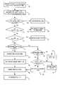
- FIG. 3illustrates a method for detecting a message in a receiver when transitioning between a wake state and a sleep state.
- a receiveris energized for a first period of time for receiving a RF message.
- a counteris set to zero and the number of preamble pulses received by the receiving circuit during the first predetermined period of time is counted.
- a determinationis made whether the first predetermined period of time has elapsed. If the determination is made that the first predetermined period of time has not elapsed, then the receiver continues polling (i.e., counting the number of preamble pulses received) during the remainder of the first period of time in step 43 .
- step 44determines whether the count is greater than or equal to the first predetermined number of preamble pulses (e.g., 10). A count equal to or greater than the first predetermined number of preamble pulses indicates that a RF message is present.
- Q-currentis provided to the receiving circuit to energize other components (e.g., the second microprocessor) to an awake state for processing the RF message and providing control actions accordingly. If the number of preamble pulses received is less than 10, then a determination is made in step 46 whether the number of preamble pulses received is greater than or equal to the second predetermined number of preamble pulses (e.g., 4). If less than 4 preamble pulses are received, then power is terminated to the receiving circuit after the first predetermined period of time has elapsed and the receiving circuit enters the sleep state in step 47 .
- the second predetermined number of preamble pulsese.g., 4
- a number of preamble pulses received during the first predetermined period of time less than 10 but greater to or equal 4indicates that potentially a RF message is present and power may be extended further for determining whether the RF message is present. Since there is an insufficient amount of preamble pulsed received accurately determined whether the RF message is present, power may be provided for an extended period of time to receive the required number of preamble pulses for make this determination.
- an extended time flagis set. If the determination is made in step 46 that less than 4 preamble pulses have been received, then the receiving circuit enters a sleep state in step 47 . If the determination is made in step 46 that the receiving circuit received 4 or more preamble pulses, then a determination is made whether the extended time flag is set in step 48 .
- step 48If the determination is made in step 48 that the extended time flag is not set, then the awake time is extended in step 54 .
- the extended time flagis thereafter set is step 55 and the counter is reset to zero in step 56 .
- step 57the receiving circuit continues to poll for preamble pulses.
- step 48determines whether the extended time is up. If the extended time has not elapsed, the polling is continued in step 50 . If the determination is made in step 50 that the extended time is up, then a determination is made in step 51 whether the last preamble pulse received is valid. If the determination is made that the last preamble pulse is invalid, then power is terminated and the receiving circuit enters a sleep mode in step 52 . If the determination is made in step 51 that the last preamble pulse is valid, then the power provided to the receiving circuit is extended for an extended period of time in step 53 . The counter is then reset in step 54 and the receiving circuit continues to poll in step 57 .
- various applications having RF functionality utilizing the adaptive wakeup detection methodmay further include, but is not limited to, remote start, remote stop, automatic sliding doors, and open/close window functions.
Landscapes
- Engineering & Computer Science (AREA)
- Computer Networks & Wireless Communication (AREA)
- Signal Processing (AREA)
- Lock And Its Accessories (AREA)
Abstract
Description
Claims (20)
Priority Applications (1)
| Application Number | Priority Date | Filing Date | Title |
|---|---|---|---|
| US10/993,860US7286859B2 (en) | 2004-11-19 | 2004-11-19 | Adaptive radio frequency wakeup detection |
Applications Claiming Priority (1)
| Application Number | Priority Date | Filing Date | Title |
|---|---|---|---|
| US10/993,860US7286859B2 (en) | 2004-11-19 | 2004-11-19 | Adaptive radio frequency wakeup detection |
Publications (2)
| Publication Number | Publication Date |
|---|---|
| US20060111062A1 US20060111062A1 (en) | 2006-05-25 |
| US7286859B2true US7286859B2 (en) | 2007-10-23 |
Family
ID=36461552
Family Applications (1)
| Application Number | Title | Priority Date | Filing Date |
|---|---|---|---|
| US10/993,860Expired - Fee RelatedUS7286859B2 (en) | 2004-11-19 | 2004-11-19 | Adaptive radio frequency wakeup detection |
Country Status (1)
| Country | Link |
|---|---|
| US (1) | US7286859B2 (en) |
Cited By (6)
| Publication number | Priority date | Publication date | Assignee | Title |
|---|---|---|---|---|
| US20070139158A1 (en)* | 2005-12-21 | 2007-06-21 | Lear Corporation | Rf protocol with variable period wakeup |
| US20100260084A1 (en)* | 2008-06-30 | 2010-10-14 | Koji Imamura | Wireless communication apparatus, terminal, system, program |
| US20100308987A1 (en)* | 2007-08-27 | 2010-12-09 | Continental Automotive Gmbh | Method for the Operation of Wheel Electronics, Wheel Electronics, and Tire Checking System |
| CN102673516A (en)* | 2012-05-30 | 2012-09-19 | 北京经纬恒润科技有限公司 | Wakeup space control method for high frequency data receiving based on SCI (serial communication interface) |
| US20140266661A1 (en)* | 2013-03-15 | 2014-09-18 | Continental Automotive Systems, Inc. | Methods, systems and devices for integration of tire pressure monitoring sensors with a tire pressure monitoring system |
| US20190007900A1 (en)* | 2017-06-30 | 2019-01-03 | Ford Global Technologies, Llc | Vehicle communications management |
Families Citing this family (21)
| Publication number | Priority date | Publication date | Assignee | Title |
|---|---|---|---|---|
| USD517976S1 (en)* | 2004-10-08 | 2006-03-28 | Nokian Tyres Plc | Tire |
| US9066194B2 (en) | 2005-07-14 | 2015-06-23 | Binj Laboratories, Inc. | System and method for detecting and controlling transmission devices |
| US11304123B1 (en) | 2005-07-14 | 2022-04-12 | Binj Laboratories, Inc. | Systems and methods for detecting and controlling transmission devices |
| US9936442B1 (en) | 2005-07-14 | 2018-04-03 | Binj Laboratories, Inc. | System and method for wrist band transmitter and system thereof |
| US10735576B1 (en)* | 2005-07-14 | 2020-08-04 | Binj Laboratories, Inc. | Systems and methods for detecting and controlling transmission devices |
| EP1908269A2 (en) | 2005-07-14 | 2008-04-09 | Binj Laboratories, Inc. | Systems and methods of detection transmission facilities |
| US8983446B2 (en) | 2005-07-14 | 2015-03-17 | Binj Laboratories, Inc. | Systems and methods for the detection and allowance of transmission facilities |
| US8626195B2 (en) | 2005-07-14 | 2014-01-07 | Binj Laboratories, Inc. | Systems and methods for detecting and controlling transmission devices |
| US9197993B2 (en) | 2005-07-14 | 2015-11-24 | Binj Laboratories, Inc | System and method for detecting and controlling transmission devices |
| US9226259B2 (en) | 2005-07-14 | 2015-12-29 | Binj Laboratories, Inc. | Systems and methods for detecting and controlling transmission devices |
| US10003685B2 (en) | 2005-07-14 | 2018-06-19 | Binj Laboratories, Inc. | Systems and methods for detecting and controlling transmission devices |
| US8238936B2 (en)* | 2006-07-14 | 2012-08-07 | Binj Laboratories, Inc. | Method and system for tracking and determining a location of a wireless transmission |
| US9037098B2 (en) | 2007-08-30 | 2015-05-19 | Binj Laboratories, Inc. | System and method for wrist band transmitter and system thereof |
| US10103806B1 (en) | 2017-06-05 | 2018-10-16 | Binj Laboratories, Inc. | System and method for wrist band transmitter and system thereof |
| US10251149B2 (en) | 2006-07-14 | 2019-04-02 | Binj Laboratories, Inc. | Method and system for tracking and determining a location of a wireless transmission |
| JP5135268B2 (en)* | 2009-03-17 | 2013-02-06 | 株式会社東芝 | Wireless system, receiver |
| US8780775B2 (en)* | 2010-05-28 | 2014-07-15 | Intel Corporation | Method and device for reducing power drain while camped on a wireless local area network |
| US9078214B2 (en)* | 2010-06-16 | 2015-07-07 | Essence Security International Ltd. | Adaptive thresholding in a Wake-On-Radio system |
| JP5808719B2 (en)* | 2012-08-30 | 2015-11-10 | 株式会社東芝 | Wireless communication device |
| KR102097987B1 (en)* | 2013-01-31 | 2020-04-07 | 삼성전자주식회사 | Apparatus and method for processing data of bluetooth in a portable terminal |
| CN107770852B (en)* | 2017-09-19 | 2021-07-27 | 联发科技(新加坡)私人有限公司 | Wireless communication method, communication device and device with storage function |
Citations (15)
| Publication number | Priority date | Publication date | Assignee | Title |
|---|---|---|---|---|
| US5305459A (en) | 1990-04-06 | 1994-04-19 | Valeo Securite Habitacle | Circuit for "waking up" a microprocessor power supply, in particular for an ID card in a car remote control system |
| US5656993A (en)* | 1995-05-08 | 1997-08-12 | Semisystems, Inc. | Vehicle wheel condition monitor and data storage system |
| US5661651A (en)* | 1995-03-31 | 1997-08-26 | Prince Corporation | Wireless vehicle parameter monitoring system |
| US5783992A (en)* | 1996-07-22 | 1998-07-21 | Delco Electronics Corp. | Time based low tire pressure warning sensor |
| US5973611A (en) | 1995-03-27 | 1999-10-26 | Ut Automotive Dearborn, Inc. | Hands-free remote entry system |
| US20010010491A1 (en) | 1999-11-02 | 2001-08-02 | Marneweck Willem J. | Signal discriminator for wake-up of a low power transponder |
| US6271748B1 (en)* | 1994-08-31 | 2001-08-07 | Andrew John Derbyshire | Tyre condition monitoring system |
| US6292096B1 (en)* | 1999-12-15 | 2001-09-18 | Trw Inc. | Apparatus and method for transmitting data in a tire condition sensing system |
| US6367022B1 (en) | 1999-07-14 | 2002-04-02 | Visteon Global Technologies, Inc. | Power management fault strategy for automotive multimedia system |
| US6535116B1 (en)* | 2000-08-17 | 2003-03-18 | Joe Huayue Zhou | Wireless vehicle monitoring system |
| US6580364B1 (en)* | 2000-07-06 | 2003-06-17 | Trw Inc. | Apparatus and method for tracking an abnormal tire condition |
| US6600428B1 (en)* | 1996-05-13 | 2003-07-29 | Micron Technology, Inc. | Radio frequency data communications device |
| US6803855B2 (en) | 2001-09-13 | 2004-10-12 | Siemens Vdo Automotive Corporation | Method for reducing average current consumption in duty-cycled RF systems |
| US7040154B2 (en)* | 2004-04-19 | 2006-05-09 | Freescale Semiconductor, Inc. | Motion sensing for tire pressure monitoring |
| US7154414B2 (en)* | 2002-03-01 | 2006-12-26 | Lear Corporation | System and method for remote tire pressure monitoring |
- 2004
- 2004-11-19USUS10/993,860patent/US7286859B2/ennot_activeExpired - Fee Related
Patent Citations (17)
| Publication number | Priority date | Publication date | Assignee | Title |
|---|---|---|---|---|
| US5305459A (en) | 1990-04-06 | 1994-04-19 | Valeo Securite Habitacle | Circuit for "waking up" a microprocessor power supply, in particular for an ID card in a car remote control system |
| US6271748B1 (en)* | 1994-08-31 | 2001-08-07 | Andrew John Derbyshire | Tyre condition monitoring system |
| US5973611A (en) | 1995-03-27 | 1999-10-26 | Ut Automotive Dearborn, Inc. | Hands-free remote entry system |
| US5661651A (en)* | 1995-03-31 | 1997-08-26 | Prince Corporation | Wireless vehicle parameter monitoring system |
| US5656993A (en)* | 1995-05-08 | 1997-08-12 | Semisystems, Inc. | Vehicle wheel condition monitor and data storage system |
| US6600428B1 (en)* | 1996-05-13 | 2003-07-29 | Micron Technology, Inc. | Radio frequency data communications device |
| US7170867B2 (en)* | 1996-05-13 | 2007-01-30 | Micron Technology, Inc. | Radio frequency data communications device |
| US6825773B1 (en)* | 1996-05-13 | 2004-11-30 | Micron Technology, Inc. | Radio frequency data communications device |
| US5783992A (en)* | 1996-07-22 | 1998-07-21 | Delco Electronics Corp. | Time based low tire pressure warning sensor |
| US6367022B1 (en) | 1999-07-14 | 2002-04-02 | Visteon Global Technologies, Inc. | Power management fault strategy for automotive multimedia system |
| US20010010491A1 (en) | 1999-11-02 | 2001-08-02 | Marneweck Willem J. | Signal discriminator for wake-up of a low power transponder |
| US6292096B1 (en)* | 1999-12-15 | 2001-09-18 | Trw Inc. | Apparatus and method for transmitting data in a tire condition sensing system |
| US6580364B1 (en)* | 2000-07-06 | 2003-06-17 | Trw Inc. | Apparatus and method for tracking an abnormal tire condition |
| US6535116B1 (en)* | 2000-08-17 | 2003-03-18 | Joe Huayue Zhou | Wireless vehicle monitoring system |
| US6803855B2 (en) | 2001-09-13 | 2004-10-12 | Siemens Vdo Automotive Corporation | Method for reducing average current consumption in duty-cycled RF systems |
| US7154414B2 (en)* | 2002-03-01 | 2006-12-26 | Lear Corporation | System and method for remote tire pressure monitoring |
| US7040154B2 (en)* | 2004-04-19 | 2006-05-09 | Freescale Semiconductor, Inc. | Motion sensing for tire pressure monitoring |
Cited By (10)
| Publication number | Priority date | Publication date | Assignee | Title |
|---|---|---|---|---|
| US20070139158A1 (en)* | 2005-12-21 | 2007-06-21 | Lear Corporation | Rf protocol with variable period wakeup |
| US20100308987A1 (en)* | 2007-08-27 | 2010-12-09 | Continental Automotive Gmbh | Method for the Operation of Wheel Electronics, Wheel Electronics, and Tire Checking System |
| US9108473B2 (en)* | 2007-08-27 | 2015-08-18 | Continental Automotive Gmbh | Method for the operation of wheel electronics, wheel electronics, and tire checking system |
| US20100260084A1 (en)* | 2008-06-30 | 2010-10-14 | Koji Imamura | Wireless communication apparatus, terminal, system, program |
| US8295218B2 (en) | 2008-06-30 | 2012-10-23 | Panasonic Corporation | Wireless communication apparatus, terminal, system, program |
| CN102673516A (en)* | 2012-05-30 | 2012-09-19 | 北京经纬恒润科技有限公司 | Wakeup space control method for high frequency data receiving based on SCI (serial communication interface) |
| US20140266661A1 (en)* | 2013-03-15 | 2014-09-18 | Continental Automotive Systems, Inc. | Methods, systems and devices for integration of tire pressure monitoring sensors with a tire pressure monitoring system |
| US9120357B2 (en)* | 2013-03-15 | 2015-09-01 | Continental Automotive Systems, Inc. | Methods, systems and devices for integration of tire pressure monitoring sensors with a tire pressure monitoring system |
| US20190007900A1 (en)* | 2017-06-30 | 2019-01-03 | Ford Global Technologies, Llc | Vehicle communications management |
| US10542493B2 (en)* | 2017-06-30 | 2020-01-21 | Ford Global Technologies, Llc | Vehicle communications management |
Also Published As
| Publication number | Publication date |
|---|---|
| US20060111062A1 (en) | 2006-05-25 |
Similar Documents
| Publication | Publication Date | Title |
|---|---|---|
| US7286859B2 (en) | Adaptive radio frequency wakeup detection | |
| KR100428880B1 (en) | Electronic controller for motor vehicle and controlling method thereof | |
| US7551057B2 (en) | Remote entry system with increased transmit power and reduced quiescent current | |
| JP4288154B2 (en) | Passive communication device and passive access control system | |
| US6236850B1 (en) | Apparatus and method for remote convenience function control with increased effective receiver seek time and reduced power consumption | |
| US7474195B2 (en) | Tire pressure monitoring and remote keyless entry system using asynchronous duty cycling | |
| US7292137B2 (en) | Energy efficient passive entry system | |
| US9085281B2 (en) | Keyless entry multi-channel RKE system | |
| US20080258870A1 (en) | Remote control system and method | |
| US20150077226A1 (en) | Method and apparatus for conserving energy in rke and tpm vehicle systems | |
| US8558664B2 (en) | Passive approach detection system and method using a unidirectional FOB | |
| US20060091996A1 (en) | Efficient RKE energy monitoring strategy | |
| US20040183651A1 (en) | Detector and lock controller using same | |
| AU3647899A (en) | Remotely controlled door lock system and method | |
| EP3329471A1 (en) | Improvement to identity code identification in polling identification | |
| JP3404219B2 (en) | Electronic control unit | |
| US20070064838A1 (en) | RF receiver ASK/FSK duty cycle optimization algorithm | |
| EP1098283A2 (en) | Passive signal discriminator for wake-up of low power transponder | |
| US20070139158A1 (en) | Rf protocol with variable period wakeup | |
| JP3746267B2 (en) | Electronic control device operated by wireless device | |
| JPH11336394A (en) | In-vehicle equipment remote control device | |
| US20050236902A1 (en) | Portable device for automotive device control system | |
| CN117593816A (en) | Electricity-saving management method and system for built-in battery of intelligent key |
Legal Events
| Date | Code | Title | Description |
|---|---|---|---|
| AS | Assignment | Owner name:LEAR CORPORATION, MICHIGAN Free format text:ASSIGNMENT OF ASSIGNORS INTEREST;ASSIGNORS:CUNNINGHAM, KEN;HEAP, SAM;MCCORMICK, GREG;AND OTHERS;REEL/FRAME:016014/0889 Effective date:20041112 | |
| STCF | Information on status: patent grant | Free format text:PATENTED CASE | |
| AS | Assignment | Owner name:JPMORGAN CHASE BANK, N.A., AS ADMINISTRATIVE AGENT Free format text:GRANT OF FIRST LIEN SECURITY INTEREST IN PATENT RIGHTS;ASSIGNOR:LEAR CORPORATION;REEL/FRAME:023519/0267 Effective date:20091109 Owner name:JPMORGAN CHASE BANK, N.A., AS ADMINISTRATIVE AGENT Free format text:GRANT OF SECOND LIEN SECURITY INTEREST IN PATENT RIGHTS;ASSIGNOR:LEAR CORPORATION;REEL/FRAME:023519/0626 Effective date:20091109 | |
| FPAY | Fee payment | Year of fee payment:4 | |
| AS | Assignment | Owner name:JPMORGAN CAHSE BANK, N.A., AS AGENT, ILLINOIS Free format text:SECURITY INTEREST;ASSIGNOR:LEAR CORPORATION;REEL/FRAME:030076/0016 Effective date:20130130 Owner name:JPMORGAN CHASE BANK, N.A., AS AGENT, ILLINOIS Free format text:SECURITY INTEREST;ASSIGNOR:LEAR CORPORATION;REEL/FRAME:030076/0016 Effective date:20130130 | |
| AS | Assignment | Owner name:LEAR CORPORATION, MICHIGAN Free format text:RELEASE BY SECURED PARTY;ASSIGNOR:JPMORGAN CHASE BANK, N.A.;REEL/FRAME:032770/0843 Effective date:20100830 | |
| REMI | Maintenance fee reminder mailed | ||
| FPAY | Fee payment | Year of fee payment:8 | |
| SULP | Surcharge for late payment | Year of fee payment:7 | |
| AS | Assignment | Owner name:LEAR CORPORATION, MICHIGAN Free format text:RELEASE BY SECURED PARTY;ASSIGNOR:JPMORGAN CHASE BANK, N.A., AS AGENT;REEL/FRAME:037701/0180 Effective date:20160104 Owner name:LEAR CORPORATION, MICHIGAN Free format text:RELEASE BY SECURED PARTY;ASSIGNOR:JPMORGAN CHASE BANK, N.A., AS AGENT;REEL/FRAME:037701/0251 Effective date:20160104 Owner name:LEAR CORPORATION, MICHIGAN Free format text:RELEASE BY SECURED PARTY;ASSIGNOR:JPMORGAN CHASE BANK, N.A., AS AGENT;REEL/FRAME:037701/0340 Effective date:20160104 | |
| AS | Assignment | Owner name:LEAR CORPORATION, MICHIGAN Free format text:RELEASE BY SECURED PARTY;ASSIGNOR:JPMORGAN CHASE BANK, N.A., AS AGENT;REEL/FRAME:037702/0911 Effective date:20160104 | |
| FEPP | Fee payment procedure | Free format text:MAINTENANCE FEE REMINDER MAILED (ORIGINAL EVENT CODE: REM.); ENTITY STATUS OF PATENT OWNER: LARGE ENTITY | |
| LAPS | Lapse for failure to pay maintenance fees | Free format text:PATENT EXPIRED FOR FAILURE TO PAY MAINTENANCE FEES (ORIGINAL EVENT CODE: EXP.); ENTITY STATUS OF PATENT OWNER: LARGE ENTITY | |
| STCH | Information on status: patent discontinuation | Free format text:PATENT EXPIRED DUE TO NONPAYMENT OF MAINTENANCE FEES UNDER 37 CFR 1.362 | |
| FP | Lapsed due to failure to pay maintenance fee | Effective date:20191023 |