US7286857B1 - Enhanced in-vehicle wireless communication system handset operation - Google Patents
Enhanced in-vehicle wireless communication system handset operationDownload PDFInfo
- Publication number
- US7286857B1 US7286857B1US09/965,232US96523201AUS7286857B1US 7286857 B1US7286857 B1US 7286857B1US 96523201 AUS96523201 AUS 96523201AUS 7286857 B1US7286857 B1US 7286857B1
- Authority
- US
- United States
- Prior art keywords
- handset
- controller
- vehicle
- display
- processing unit
- Prior art date
- Legal status (The legal status is an assumption and is not a legal conclusion. Google has not performed a legal analysis and makes no representation as to the accuracy of the status listed.)
- Expired - Lifetime, expires
Links
- 238000004891communicationMethods0.000titleclaimsabstractdescription42
- 238000012545processingMethods0.000claimsdescription44
- 238000000034methodMethods0.000claimsdescription42
- 230000015654memoryEffects0.000claimsdescription19
- 230000001413cellular effectEffects0.000claimsdescription15
- 230000010365information processingEffects0.000claims11
- 230000001755vocal effectEffects0.000abstractdescription4
- 230000000007visual effectEffects0.000description13
- 238000007726management methodMethods0.000description10
- 230000006870functionEffects0.000description8
- 238000005516engineering processMethods0.000description6
- 230000015572biosynthetic processEffects0.000description4
- 238000013479data entryMethods0.000description3
- 239000004973liquid crystal related substanceSubstances0.000description3
- 230000003068static effectEffects0.000description3
- 238000003786synthesis reactionMethods0.000description3
- 238000010586diagramMethods0.000description2
- 230000002708enhancing effectEffects0.000description2
- 230000004313glareEffects0.000description2
- 238000011160researchMethods0.000description2
- 230000004044responseEffects0.000description2
- 239000010409thin filmSubstances0.000description2
- 102100039995Arginyl-tRNA-protein transferase 1Human genes0.000description1
- 101000886906Homo sapiens Arginyl-tRNA-protein transferase 1Proteins0.000description1
- 230000005540biological transmissionEffects0.000description1
- 239000000872bufferSubstances0.000description1
- 238000012790confirmationMethods0.000description1
- 238000012423maintenanceMethods0.000description1
- 229920001690polydopaminePolymers0.000description1
Images


Classifications
- H—ELECTRICITY
- H04—ELECTRIC COMMUNICATION TECHNIQUE
- H04M—TELEPHONIC COMMUNICATION
- H04M1/00—Substation equipment, e.g. for use by subscribers
- H04M1/60—Substation equipment, e.g. for use by subscribers including speech amplifiers
- H04M1/6033—Substation equipment, e.g. for use by subscribers including speech amplifiers for providing handsfree use or a loudspeaker mode in telephone sets
- H04M1/6041—Portable telephones adapted for handsfree use
- H04M1/6075—Portable telephones adapted for handsfree use adapted for handsfree use in a vehicle
- H—ELECTRICITY
- H04—ELECTRIC COMMUNICATION TECHNIQUE
- H04L—TRANSMISSION OF DIGITAL INFORMATION, e.g. TELEGRAPHIC COMMUNICATION
- H04L67/00—Network arrangements or protocols for supporting network services or applications
- H04L67/50—Network services
- H04L67/52—Network services specially adapted for the location of the user terminal
- H—ELECTRICITY
- H04—ELECTRIC COMMUNICATION TECHNIQUE
- H04M—TELEPHONIC COMMUNICATION
- H04M1/00—Substation equipment, e.g. for use by subscribers
- H04M1/26—Devices for calling a subscriber
- H04M1/27—Devices whereby a plurality of signals may be stored simultaneously
- H04M1/271—Devices whereby a plurality of signals may be stored simultaneously controlled by voice recognition
- H—ELECTRICITY
- H04—ELECTRIC COMMUNICATION TECHNIQUE
- H04M—TELEPHONIC COMMUNICATION
- H04M2250/00—Details of telephonic subscriber devices
- H04M2250/10—Details of telephonic subscriber devices including a GPS signal receiver
- H—ELECTRICITY
- H04—ELECTRIC COMMUNICATION TECHNIQUE
- H04W—WIRELESS COMMUNICATION NETWORKS
- H04W48/00—Access restriction; Network selection; Access point selection
- H04W48/08—Access restriction or access information delivery, e.g. discovery data delivery
- H—ELECTRICITY
- H04—ELECTRIC COMMUNICATION TECHNIQUE
- H04W—WIRELESS COMMUNICATION NETWORKS
- H04W64/00—Locating users or terminals or network equipment for network management purposes, e.g. mobility management
- H—ELECTRICITY
- H04—ELECTRIC COMMUNICATION TECHNIQUE
- H04W—WIRELESS COMMUNICATION NETWORKS
- H04W88/00—Devices specially adapted for wireless communication networks, e.g. terminals, base stations or access point devices
- H04W88/02—Terminal devices
Definitions
- In-vehicle operation of a radio (wireless) telephone handsetand in particular enhancing the operation of a cellular telephone handset by using an in-vehicle data terminal that is associated with a motor vehicle fleet management system.
- In-vehicle fleet management systemsthat communicate the vehicle's location, for example as determined by using Global Positioning System (GPS) information, to a central location are known.
- GPSGlobal Positioning System
- Such systemse.g., the FLEETASAPTM motor vehicle fleet management system produced by At Road, Inc., Fremont, Calif.
- Such systemstypically include a location manager that determines the vehicle position and a data terminal electrically coupled to the location manager.
- a wireless modem in the location managertypically facilitates communication between the location manager and a central computer platform configured to act as a server (provider of specific facilities to client devices) via, for example, a cellular telephone system.
- the servercommunicates data (e.g., messages) to the location manager for output on the data terminal.
- Fleet management systemsalso typically offer two-way message capability between the fleet operator and individual fleet vehicle drivers.
- wireless (radio) handsetse.g., cellular telephone handsets, personal digital assistants
- PCSPersonal Communications System
- SMSShort Message Service
- a serveror in the form of electronic mail (email) from a personal computer, are routed to the PCS handset for output on the handset display.
- Wireless handsetshave become increasingly smaller. This small size often makes handset operation difficult, especially in a motor vehicle. For example, handset dial pad buttons are small.
- handset visual displayse.g., liquid crystal display
- text messagesthat are output on the displays are difficult to read due to small character size and the limited amount of characters that are displayed.
- In-vehicle handset operation and message displayis further limited during poor lighting conditions such as sunlight glare or during nighttime.
- handsetsare often mounted in holders attached to the vehicle dashboard so that the handset is difficult to access and view from the driver's position. Therefore, it is desirable to provide enhanced in-vehicle wireless telephone handset operation. It is also desirable that such enhanced operation include enhanced text message output. Since a device external to the handset is used to provide such operating enhancements, it is desirable to warn the vehicle operator when the handset is not connected to the enhancing device.
- a wireless communication system handset(e.g., cellular) is coupled to communicate via a wired or wireless (radio; e.g., BLUETOOTH) link with a handset controller positioned in a motor vehicle.
- the handset controlleris programmed to execute instructions that allow the controller to control operations of the handset. These operations include sending and receiving messages (e.g., short message service messages) via the handset, and dialing telephone numbers.
- the handset controlleralso warns the user if the handset is, or becomes, disconnected from the controller.
- the handset controllerincludes input keys that are larger (e.g., on the scale of conventional keys on a desk top computer keyboard) than the keys on the handset.
- the number of controller input keysis larger than the number of keys on the handset, thereby enabling features such as dialing a telephone number by pressing a single button (one step dialing).
- the controlleralso includes a display significantly larger (e.g., 2 inches high ⁇ 6 inches wide, or more) than the handset display.
- the controller displayis capable of displaying message text characters that are larger than the characters output on the handset display, and is also capable of displaying a larger amount of message text than can be output on the handset display.
- the larger keys and larger displayfacilitate handset operation by a user in a motor vehicle. In one case the input keys and the display are backlighted to enhance their visibility in the vehicle interior environment.
- the handset controllerincludes a voice command input unit that allows the user to control the handset by speaking voice commands, and includes a voice synthesis output unit that allows messages received by the handset to be audibly output to the user in a synthesized voice.
- the handset controlleris part of a system that determines the geographic position of the vehicle (e.g., by using GPS) that relays the determined position to a remote server.
- FIG. 1is a diagrammatic view showing a handset controller coupled to a handset within the interior of a motor vehicle.
- FIG. 2is flow diagram showing a procedure executed by a handset controller.
- FIG. 3is a diagrammatic view showing an embodiment of a handset controller.
- FIG. 4is a diagrammatic view showing elements of the embodiment in FIG. 3 in more detail.
- FIG. 5is a diagrammatic view illustrating operation of a handset controller.
- FIG. 1is a diagrammatic view of one embodiment of an in-vehicle telephone handset operating system.
- motor vehicle 10e.g., a delivery vehicle
- Handset 12 and controller 14are coupled via conventional communications link 16 , which is in one case a hardware link (e.g., cable) and in a second case a wireless link (e.g., BLUETOOTHTM wireless technology).
- conventional communications link 16is in one case a hardware link (e.g., cable) and in a second case a wireless link (e.g., BLUETOOTHTM wireless technology).
- a hardware linke.g., cable
- wireless linke.g., BLUETOOTHTM wireless technology
- handset 12is a cellular telephone handset, but persons skilled in the art will understand that handset 12 may be, for example, a paging system receiver or a combination of a cellular telephone handset and personal digital assistant (PDA), such as the VISORPHONETM manufactured by Handspring, Inc., Mountain View, Calif. In some cases in which a PDA is used, portions of the PDA are configured to act as parts of controller 14 .
- PDApersonal digital assistant
- Controller 14includes central processor unit (CPU) 18 , memory 20 , input unit 22 , and output unit 24 .
- CPU 18is conventional and executes coded instructions to externally control handset 12 features such as dialing; sending, receiving, managing, and outputting messages to the user using, for example, the short message service (SMS); managing internally stored telephone number lists (personal telephone books); and any other feature enabled in handset 12 , if desired.
- SMSshort message service
- personal telephone bookspersonal telephone books
- Memory 20is, for example, random access memory (e.g., SRAM) and read-only memory (e.g., flash memory).
- Information stored in memory 20includes images of information stored in handset 12 (e.g., configuration data, text messages), as well as coded instructions (e.g., software) for operating controller 14 .
- CPU 18is coupled to receive inputs from the user via input unit 22 so as to control handset 12 operation.
- input unit 22includes input keys, such as a conventional numeric keypad or conventional QWERTY keyboard.
- input unit 22has other buttons or switches (e.g., function keys) for specific data entry functions, as well as cursor control keys.
- the keys on input unit 22are significantly larger (e.g., on the scale of conventional keys on a desk top computer keyboard—at least 0.5-inch ⁇ 0.5-inch each) than the keypad buttons on handset 12 (typically all arranged in a 1.5-inch ⁇ 1.5-inch array), thereby allowing the user to more easily enter control commands (e.g., handset dialing, one-step speed dialing, received message management) and data (e.g., personal telephone book information) for handset 12 .
- control commandse.g., handset dialing, one-step speed dialing, received message management
- datae.g., personal telephone book information
- the keypadis rigidly mounted in the vehicle to facilitate one-hand operation by the user.
- the keypadis backlighted to improve visibility in low light conditions.
- input unit 22includes a microphone coupled to pass the user's voice to handset 12 during a telephone conversation. Other voice input capability is described below.
- Output unit 24includes a conventional visual display (e.g., liquid crystal, thin film transistor) that displays, for example, messages received via handset 22 .
- the output unit 24 displayis larger (e.g., 2-inch ⁇ 6-inch or more) than the visual display in handset 12 (typically 0.5-inch ⁇ 1.5-inch, thereby allowing the user to view more message text at one time (either from single or multiple messages).
- font sizes displayed on the unit 24 displayare larger (e.g., 0.5-inch) than are displayed on the handset 12 display.
- Such larger font sizesallow the user to easily read displayed text from the driver's seat when unit 24 is in a fixed position in the vehicle (e.g., 2-3 feet from the driver's eyes).
- the displayis mounted in the vehicle so as to be easily visible from the driver's seat.
- the visual displayis backlighted to optimize the display contrast in the motor vehicle environment, thereby allowing the user to more easily view the output presented on the display.
- output unit 24includes a conventional amplifier and speaker that amplifies the received portion of a telephone conversation. Other voice output capability is described below.
- the useroperates handset 12 using controller 14 .
- Inputs normally made on handset 12 's keypadare made instead via input unit 22 .
- outputs normally made on handset 12 's visual displayare made via output unit 24 .
- the larger size and enhanced visibility of the input keys and output displaysfacilitates user operation in the vehicle.
- Embodiments of the in-vehicle telephone handset operating system as shown in FIG. 1include the capability to receive the user's voice commands and to output synthesized voice information to the user.
- input unit 22includes conventional speech recognition technology, such as that produced by Lernout & Hauspie Speech Products, N.V., Belgium, or such as that produced by Cellport Systems, Boulder Colo.
- output unit 24includes conventional speech synthesis technology such as REALSPEAKTM by Lernout & Hauspie.
- voice commands to control handset 12 operationenhances safety since it allows a user to operate handset 12 while keeping their hands on the vehicle controls. Further, audible output of text messages also enhances safety because it allows a user to access text information without moving their eyes from the road to see the display screen.
- FIG. 2illustrates an embodiment of a process periodically executed (e.g., once per second) by CPU 18 to monitor handset 12 connection status.
- a phone status flag in memory 20indicates the handset 12 status as either “connected” or “not connected” and is initially set to “not connected.”
- CPU 18In 50 the phone status flag is checked. If the status is “not connected” then CPU 18 detects in 52 if the handset is connected. In one case CPU 18 checks for connection using hardware (e.g., using RS232 Data Set Ready (DSR) line). In another case CPU 18 checks for connection using software (e.g., sending the AT command ATE1 to force echoing).
- hardwaree.g., using RS232 Data Set Ready (DSR) line.
- DSRData Set Ready
- softwaree.g., sending the AT command ATE1 to force echoing.
- CPU 18examines the result of 52 . If the result in 52 indicates that handset 12 is not connected, the connection status flag remains “not connected” and in 55 CPU 18 outputs to the user a warning (either visible or audible) via output unit 24 that handset 12 is not connected. In some instances an audible warning in 55 is output if handset 12 is not connected and the vehicle engine is started. In some instances the audible warning in 55 is output if handset 12 is not connected and the vehicle begins moving.
- a warningeither visible or audible
- CPU 18reinitializes handset 12 .
- Reinitializationincludes issuing a telephone reset command (e.g., ATZ command); setting, for example, telephone configuration; and reading handset 12 's Internet Protocol (IP) address, SMS lists, and internally stored telephone number lists.
- IPInternet Protocol
- handset 12is configured to communicate with controller 14 using, for example, point-to-point protocol (PPP) or serial line IP (SLIP).
- PPPpoint-to-point protocol
- SLIPserial line IP
- connection status in 50is “connected,” then in 60 CPU 18 detects if handset 12 is connected using procedures similar to those in 52 .
- CPU 18examines the result of 60 . If the result in 60 indicates that handset 12 is not connected, in 64 CPU 18 resets the connection status flag to “not connected” and CPU 18 outputs to the user a warning (either visible or audible) via output unit 24 that handset 12 is not connected. If the result in 62 indicates that handset 12 remains connected, then in 66 CPU 18 queries handset 12 to determine if the handset is in or out of service. In one case a telephone handset is queried using conventional AT commands. In another case in which the connection to the telephone handset is using PPP or SLIP, the query is done using proprietary queries.
- CPU 18determines in 66 that handset 12 is in service, in 70 CPU checks for commands and data to be received or transmitted between handset 12 and handset controller 14 .
- commands and datainclude IP data to transmit or receive, newly received SMS messages, and the user's handset control inputs from input unit 22 .
- the commands and data sent to or received from handset 12are asynchronously sent or received via low level serial interface buffers in controller 14 .
- CPU 18checks for personal phonebook, SMS list changes, and other stored data updates in handset 12 . Since many telephone handsets allow the user to edit SMS messages and personal phone books via the handset's user interface, it is necessary to update the SMS list and personal telephone book information stored in memory 20 with the latest information from handset 12 .
- FIG. 3is a diagrammatic view of an embodiment of an in-vehicle telephone handset controller.
- control unit 14includes processing unit 102 (e.g., At Road, Inc., part no. iLM2000 “Location Manager”) and data terminal 104 (e.g., At Road, Inc., part no. iDT2000 “Data Terminal”).
- processing unit 102is part of a motor vehicle fleet management system and includes a conventional global positioning system (GPS) chipset to determine the unit 102 position from GPS signals received via conventional antenna 106 . The determined position is sent to a remote fleet management system computer via a wireless modem in processing unit 102 or in one case, via handset 12 .
- GPSglobal positioning system
- Handset 12is coupled to processing unit 102 at serial communications port 108 .
- handset 12is mounted in holder 110 that is attached to, for example, vehicle 10 's dashboard.
- communications link 16is either hardware (e.g., serial communications cable) or wireless (e.g., BLUETOOTHTM).
- link 16is hardware, the battery in handset 12 is charged via link 16 from processing unit 102 .
- Data terminal 104is coupled to processing unit 102 at port 112 .
- data terminal 104includes numeric keypad 114 , cursor control 116 , data entry keys 118 (e.g., specific function keys, QWERTY alphanumeric keys), and visual display 120 .
- terminal 104is secured (using, e.g., a rigid bracket) to vehicle 10 in a position to allow the user to view display 120 and to operate keys 114 , 118 from the driver's position.
- data terminal 104includes a conventional audio speaker (not shown) for audio output of data to the user.
- display 120 and data entry keys 118are combined as a conventional LCD touch screen.
- Terminal 104may include voice recognition (command and control) capability as described below.
- Optional auxiliary data source 122is coupled to port 124 on processing unit 102 via conventional communications cable 126 .
- Data source 122is illustrative of one of many in-vehicle data sources such as a vehicle data bus, a bar code scanner, a QWERTY keyboard input, temperature sensors, vehicle door status sensors, and driver seat pressure sensors. In other embodiments data source 122 is coupled to data terminal 104 .
- the userenters one or more “dialing/control” modes by pressing one or more keys on keyboard 118 in data terminal 104 . Confirmation that the appropriate “dialing/control” mode has been selected is displayed on display 120 .
- the userenters a telephone number using keypad 114 .
- the dialed telephone numberidentifies a text message destination.
- the userenters one or more text messages using keyboard 118 or data source 122 configured as a QWERTY keyboard.
- the vehicle operatorenters a “send” command on data terminal 104 that directs handset 12 to transmit the entered message to, for example, the destination identified by the previously entered telephone number.
- a “server display” modeAfter sending the text message, the user enters a “server display” mode by entering another command on keyboard 118 to view, for example, fleet management information.
- These “dialing/control,” “send,” and “server display” commandsare illustrative of many possible commands that are entered on data terminal 104 for controlling handset 12 operation.
- voice unit 130is coupled to port 132 on processing unit 102 via cable 134 .
- voice unit 130is coupled to handset 12 as shown by alternate link (wired or wireless) 135 .
- voice unit 130 and terminal 104may operate using the same interface, thereby providing alternate input/output implementations.
- Unit 130 and terminal 104may be combined in a single unit in some embodiments, so that voice commands are used to replace one or more key or button inputs on terminal 104 .
- voice unit 130includes both voice command input unit 136 and voice synthesizer unit 138 .
- the userspeaks one or more commands which the speech recognition technology in voice command input unit 136 converts to commands to be executed by controller 14 to control handset 12 operation. For instance, to dial a telephone number the user speaks a “dial number” command, then speaks the number to be dialed, and finally speaks a “dial” command. Controller 14 receives these commands and the number to be dialed, and controls handset 12 to dial the user's desired number. In another instance, the user controls the display of messages on display 120 by speaking a “message display” command. In response, data terminal 104 displays messages received and stored by handset 12 on display 120 .
- the userselects one of the displayed messages to be read (e.g., message number 1) and speaks a command to read the selected message (e.g., “read one”).
- the voice synthesizer in synthesizer unit 138outputs a spoken version of the selected message text.
- synthesizer unit 138outputs synthesized speech for each received message that includes sender name and message subject so as to allow the user to select the message to be output.
- Received messagesare managed using, for example, “store” and “delete” verbal commands.
- the verbal commands described hereinare illustrative and skilled artisans will realize that many acceptable command and control functions exist to operate handset 12 .
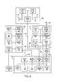
- FIG. 4is a functional diagram showing components of processing unit 102 , data terminal 104 , handset 12 , and voice unit 130 . As depicted in FIG. 4 , terminal 104 , handset 12 , and voice unit 130 are coupled to processing unit 102 via hardware (e.g., cables) but wireless connections are used in other cases.
- hardwaree.g., cables
- Processing unit 102includes location unit 150 , power supply 152 , input/output (I/O) unit 154 , central processor unit 156 , flash memory 158 , and static random access memory 160 .
- location unit 150includes a conventional GPS chip set. Unit 150 receives GPS signals via antenna 106 and determines processing unit 102 's geographic location. In an alternative embodiment, location unit 150 determines geographic location from other ground-based signals, such as from cellular telephone signals that are received via antenna 106 or via handset 12 .
- Conventional power supply 152provides electric power to components in processing unit 102 .
- power supply 152is electrically coupled to motor vehicle battery 164 which supplies electric power to power supply 152 .
- Conventional input/output unit 154includes controls (e.g., buttons, switches) to allow the user to control processing unit 102 operation. Input/output unit 154 also includes output indicators (e.g., lights) that display information regarding unit 102 operation to the user or to system maintenance personnel.
- controlse.g., buttons, switches
- output indicatorse.g., lights
- CPU 156includes a conventional microprocessor/microcontroller (the terms are synonymous as used herein) with associated circuits, and executes coded instructions to control both processing unit 102 and handset 12 operation.
- Conventional memories 158 , 160are illustrative of memory capacity in processing unit 102 .
- flash memory 158 and conventional SRAM 160store instructions and data used by CPU 156 during processing unit 102 operation. For example, stored instructions direct CPU 156 to execute the procedure described with reference to FIG. 2 .
- processing unit 102includes three communications ports 164 , 166 , 168 .
- ports 164 , 166 , 168are conventional serial ports. In other cases other communications protocol ports are used.
- port 168is also used as a battery charger terminal to charge, for example, the battery in handset 12 , thereby ensuring that the battery is charged when the user removes handset 12 from vehicle 10 .
- FIG. 4shows handset 12 and processing unit 102 electrically coupled via conventional cable 170 between ports 168 and 172 .
- Cable 170includes conventional level shifter 174 and is connected to ports 168 , 172 using, for example, RJ45 connectors.
- level shifter 174is omitted.
- PCS handset manufacturersuse various unique serial interface protocols to facilitate communication using port 172 .
- the handset interface software in processing unit 102is capable of proper communication with one or more of such protocols.
- handset 12 and processing unit 102are coupled using a wireless link such as the well-known BLUETOOTHTM short-range omnidirectional wireless data link protocol.
- Handset 12includes conventional audio/visual output unit 176 , conventional transceiver and modem unit 178 , conventional keypad 180 , conventional microcontroller and memory unit 182 , and conventional battery 184 , all of which are illustrative of components in a conventional wireless telephone handset, such as a NEXTEL model no. I700PLUSTM data capable unit that uses the Motorola, Inc. IDEN® technology system, and also other devices including PDAs with telephone capability.
- a PDAperforms the handset 12 functions
- the same PDAmay perform some or all of the data terminal 104 functions as described below.
- handset 12may be a cellular telephone handset and the PDA performs some or all of the data terminal 104 functions.
- Audio-visual output unit 176includes a conventional audio output (not shown) that outputs telephone sound to the user when operating handset 12 as a stand-alone unit. In some cases output unit 176 also includes a conventional visual display (e.g., LCD display) (not shown) that outputs visible text to the user. Transceiver and modem unit 178 sends and receives radio signals via conventional antenna 186 . These signals include conventionally coded voice and message information such as a telephone conversation between two parties, a paging signal, or a Personal Communications System (PCS) Short Message Service (SMS) text message. These signals may also include information representing images (e.g., World Wide Web pages) and video (e.g., MPEG file).
- imagese.g., World Wide Web pages
- videoe.g., MPEG file
- Keypad 180is a conventional cellular telephone keypad and includes numeric keys used to dial telephone numbers.
- Microcontroller and memory unit 182includes a microcontroller/microprocessor that controls handset 12 operation using coded instructions (e.g., software, firmware) that are stored in the memory portion. In some instances these instructions are modified to conform with embodiments as described herein.
- the memory portionalso includes locations at which received information or information to be transmitted is stored.
- Battery 184provides electric power to operate handset 12 and in some cases is charged by processing unit 102 through port 172 as illustrated by optional cable 185 that couples power supply 152 and battery 184 . For instances in which a separate battery 184 charging input terminal is provided on handset 12 , cable 185 further illustrates that power supply 152 charges battery 184 via such a separate terminal.
- Data terminal 104is coupled to processing unit 102 (and thereby is coupled to handset 12 ) via conventional cable 192 between ports 164 and 194 .
- data terminal 104is a proprietary terminal (e.g., iDT2000) and in other cases terminal 104 is a part of another data processing system (e.g., portable laptop computer, personal digital assistant, etc.).
- application programse.g., electronic mail programs, World Wide Web browser programs
- stored on the data processing systemmay be operated by using the wireless interface provided by handset 12 .
- data terminal 104includes components that are illustrative of many systems, including conventional visual output display 196 , conventional keyboard 198 , conventional CPU 200 , conventional static RAM 202 , conventional flash memory 204 , and conventional power supply 206 .
- Display 196is, for example, a conventional liquid crystal or thin film transistor display. In some cases display 196 is conventionally backlighted or otherwise provided a high visual contrast. This high contrast display allows the user to more clearly see the output on display 196 in poor viewing conditions such as low ambient light or sun glare. In some embodiments the display contrast is optimized with respect to the specific viewing conditions in the vehicle.
- visual outputis via a heads-up display unit 196 a , mounted so that a visual output display focused at infinity is seen by the driver while looking through the windshield.
- Heads-up display 196 amay replace or may be in addition to display 196 .
- Keyboard 198is illustrative of user data input capability, and in one case includes buttons that the user presses to input various commands (e.g., display message, send message) to data terminal 104 .
- keyboard 198includes a QWERTY keyboard used to input text information into terminal 104 .
- keyboard 198includes a conventional cursor control input for controlling a cursor displayed on display 196 .
- the buttons on keyboard 198are larger than those on keypad 180 (e.g., the size of conventional typewriter keys), thereby allowing the user to more easily control handset 12 functions while in the vehicle.
- the buttons and controls on keyboard 198are conventionally backlighted so as to allow the user to more easily see the buttons and controls in poor viewing conditions.
- CPU 200includes a conventional microprocessor/microcontroller with associated circuits, and controls data terminal 104 operation.
- Static RAM 202 and flash memory 204store instructions (e.g., software, firmware) used by CPU 200 to operate data terminal 104 .
- Memories 202 , 204are also used to store data for display on display 196 and/or to store data entered using keyboard 198 .
- Conventional power supply 206supplies electric power to components of data terminal 104 and is, in one case, coupled to vehicle battery 206 .
- Voice unit 130is coupled to processing unit 102 via conventional cable 210 between ports 166 and 212 .
- Voice unit 130includes the combination of voice input unit 214 and microphone 216 , and also the combination of voice output unit 218 and speaker 220 .
- Voice unit 130is shown separate, but in some cases is combined with data terminal 104 .
- Voice input unit 214includes a microprocessor executing speech recognition software (e.g., manufactured by Lernout & Hauspie) and allows the user to operate handset 12 features by giving voice commands instead of manual inputs using, for example, keyboard 198 or keypad 180 .
- Voice output unit 218converts data (e.g., text message, message management information) to a synthesized voice output via speaker 220 .
- a text messagemay be displayed on display 196 and/or audibly output by output unit 218 .
- speaker 220is the speaker associated with the motor vehicle's radio.
- Voice output unit 218includes a microprocessor executing voice synthesis software, (e.g., REALSPEAKTM).
- voice unit 130is coupled directly to handset 12 as shown by alternate communications link (wired or wireless (e.g., BLUETOOTH)) 222 . In this manner provides control inputs to, and receives outputs from, handset 12 .
- alternate communications linkwireless or wireless (e.g., BLUETOOTH)
- FIG. 5is a diagrammatic view illustrating operation of one embodiment.
- Handset controller 14receives signals 250 from GPS satellites 252 via antenna 106 and then determines vehicle 10 's geographic position. Controller 14 transmits the location information (for example, using a dedicated wireless modem coupled to antenna 106 or using handset 12 ) via cellular telephone system 254 and mobile switching center 256 to conventional computer platform 258 , which is programmed to act as a motor vehicle fleet management server (e.g., FLEETASAPTM by At Road, Inc.).
- the transmission of location informationis illustrative of the data that may be transmitted from controller 14 to computer (server) 258 , such data including all information supplied by one or more auxiliary data sources 122 ( FIG. 3 ) in vehicle 10 .
- cellular system 254 and mobile switching center 256are illustrative of other wireless communication systems (e.g., metro- or wide-area wireless networks) used to route information from vehicle 10 to and from computer (server) 258 .
- Computer (server) 258may send data to handset controller 14 for output on output unit 24 .
- datais sent from computer (server) 258 directly to mobile switching center 256 .
- message text datais sent from computer (server) 258 to mobile switching center 256 via short message service center 260 .
- informationalso passes between conventional computer 262 and controller 14 via the Internet 264 (network of interconnected networks, having its origins in research by the United States Advanced Research Projects Agency), conventional Internet gateway 266 , mobile switching center 256 , cellular system 254 , and handset 12 .
- Computer (server) 258 and computer 262illustrate that handset 12 may receive messages in various formats sent via different protocols.
- handset 12 and/or controller 14differentiates among the various message formats and protocols that are received and outputs each received message in the sender's intended format via output unit 24 .
- handset 12identifies both electronic mail format and SMS format messages, and received messages are correctly output to the user as intended by the email and SMS message senders.
- the user in vehicle 10controls handset 12 operation and both sends and receives information from illustrative computer (server) 258 and computer 262 .
- the large visual display in output unit 24allows the user to more clearly view received messages and to more easily sort and otherwise manage several received messages.
- the large input keys in input unit 22allow the user to more easily input handset 12 control commands and data to be sent to computer (server) 258 or computer 262 .
- User operation and motor vehicle safetyis further enhanced in embodiments using voice input and output as described herein. Further, by using verbal commands and receiving audio output, the vehicle driver saves time by being able to drive the vehicle while simultaneously accessing, managing, and outputting text messages without having to take his or her hands from the steering wheel.
- Embodimentsare also used to alert the user about short-notice cargo pickups while the user is enroute between planned stops, thus preventing the need for the user to backtrack to make the pickup after checking for messages during a subsequent planned stop.
- the enhanced control of the telephone handsethas been described in terms of specific embodiments, but other embodiments exist, and software coding for all embodiments is routine in light of this disclosure. Accordingly, persons skilled in the art will understand that many variations of the invention as described herein are possible, and that the scope of the invention is defined by the following claims.
Landscapes
- Engineering & Computer Science (AREA)
- Signal Processing (AREA)
- Computer Networks & Wireless Communication (AREA)
- Mobile Radio Communication Systems (AREA)
Abstract
Description
Claims (54)
Priority Applications (1)
| Application Number | Priority Date | Filing Date | Title |
|---|---|---|---|
| US09/965,232US7286857B1 (en) | 2001-09-25 | 2001-09-25 | Enhanced in-vehicle wireless communication system handset operation |
Applications Claiming Priority (1)
| Application Number | Priority Date | Filing Date | Title |
|---|---|---|---|
| US09/965,232US7286857B1 (en) | 2001-09-25 | 2001-09-25 | Enhanced in-vehicle wireless communication system handset operation |
Publications (1)
| Publication Number | Publication Date |
|---|---|
| US7286857B1true US7286857B1 (en) | 2007-10-23 |
Family
ID=38607109
Family Applications (1)
| Application Number | Title | Priority Date | Filing Date |
|---|---|---|---|
| US09/965,232Expired - LifetimeUS7286857B1 (en) | 2001-09-25 | 2001-09-25 | Enhanced in-vehicle wireless communication system handset operation |
Country Status (1)
| Country | Link |
|---|---|
| US (1) | US7286857B1 (en) |
Cited By (48)
| Publication number | Priority date | Publication date | Assignee | Title |
|---|---|---|---|---|
| US20050135573A1 (en)* | 2003-12-22 | 2005-06-23 | Lear Corporation | Method of operating vehicular, hands-free telephone system |
| US20050221868A1 (en)* | 2004-03-25 | 2005-10-06 | International Business Machines Corporation | Method and apparatus for volume reduction in a vehicle |
| US20060089176A1 (en)* | 2003-09-17 | 2006-04-27 | Sanyo Electric Co., Ltd. | Acoustic device for vehicle |
| US20060161340A1 (en)* | 2005-01-14 | 2006-07-20 | Lee Don S | Multifunctional OBE for its |
| US20060189278A1 (en)* | 2005-02-24 | 2006-08-24 | Research In Motion Limited | System and method for making an electronic handheld device more accessible to a disabled person |
| US20060206817A1 (en)* | 2005-02-28 | 2006-09-14 | Jung Edward K | User assistance for a condition |
| US20070042812A1 (en)* | 2005-06-13 | 2007-02-22 | Basir Otman A | Vehicle immersive communication system |
| US20070109096A1 (en)* | 2005-09-08 | 2007-05-17 | Jeremy Breedlove | Global tracking and communications device |
| US20070155439A1 (en)* | 2006-01-05 | 2007-07-05 | Huo-Lu Tsai | Dial system for a steering wheel of an automobile |
| US20070213092A1 (en)* | 2006-03-08 | 2007-09-13 | Tomtom B.V. | Portable GPS navigation device |
| US20070259674A1 (en)* | 2006-03-08 | 2007-11-08 | Edwin Neef | Automatic discovery of wireless communication settings |
| US20080027643A1 (en)* | 2006-07-28 | 2008-01-31 | Basir Otman A | Vehicle communication system with navigation |
| US20080313050A1 (en)* | 2007-06-05 | 2008-12-18 | Basir Otman A | Media exchange system |
| US20080312828A1 (en)* | 2006-02-15 | 2008-12-18 | Marsalka Joseph P | System and method for providing directions |
| US20090164110A1 (en)* | 2007-12-10 | 2009-06-25 | Basir Otman A | Vehicle communication system with destination selection for navigation |
| US20090234651A1 (en)* | 2008-03-12 | 2009-09-17 | Basir Otman A | Speech understanding method and system |
| US20090248420A1 (en)* | 2008-03-25 | 2009-10-01 | Basir Otman A | Multi-participant, mixed-initiative voice interaction system |
| US20090287401A1 (en)* | 2008-05-19 | 2009-11-19 | Uri Levine | System and method for realtime community information exchange |
| US20100057336A1 (en)* | 2008-08-27 | 2010-03-04 | Uri Levine | System and method for road map creation |
| US20100184406A1 (en)* | 2009-01-21 | 2010-07-22 | Michael Schrader | Total Integrated Messaging |
| US20100204878A1 (en)* | 2007-08-09 | 2010-08-12 | Michael Drew | Modular Vehicular Diagnostic Tool |
| US20110153150A1 (en)* | 2007-08-09 | 2011-06-23 | Michael Drew | Vehicle Tuner And Display Module And Docking Station |
| US20120183221A1 (en)* | 2011-01-19 | 2012-07-19 | Denso Corporation | Method and system for creating a voice recognition database for a mobile device using image processing and optical character recognition |
| US20130282375A1 (en)* | 2007-06-01 | 2013-10-24 | At&T Mobility Ii Llc | Vehicle-Based Message Control Using Cellular IP |
| US8577543B2 (en) | 2009-05-28 | 2013-11-05 | Intelligent Mechatronic Systems Inc. | Communication system with personal information management and remote vehicle monitoring and control features |
| US20140088798A1 (en)* | 1999-09-10 | 2014-03-27 | Seong Sang Investments Llc | Communications between a mobile device and vehicle based computer |
| US20140160667A1 (en)* | 2012-12-06 | 2014-06-12 | Harman Becker Automotive Systems Gmbh | Vehicle multimedia system and vehicle |
| US8838075B2 (en) | 2008-06-19 | 2014-09-16 | Intelligent Mechatronic Systems Inc. | Communication system with voice mail access and call by spelling functionality |
| US9086948B1 (en) | 2013-03-13 | 2015-07-21 | Allstate Insurance Company | Telematics based on handset movement within a moving vehicle |
| EP2874327A4 (en)* | 2012-06-20 | 2016-03-02 | Mitsubishi Electric Corp | EXTERNAL BATTERY AND SATELLITE COMMUNICATION TERMINAL |
| US9307577B2 (en) | 2005-01-21 | 2016-04-05 | The Invention Science Fund I, Llc | User assistance |
| US9652023B2 (en) | 2008-07-24 | 2017-05-16 | Intelligent Mechatronic Systems Inc. | Power management system |
| US9667726B2 (en) | 2009-06-27 | 2017-05-30 | Ridetones, Inc. | Vehicle internet radio interface |
| US9747579B2 (en) | 2004-09-30 | 2017-08-29 | The Invention Science Fund I, Llc | Enhanced user assistance |
| US9756163B2 (en) | 2010-08-09 | 2017-09-05 | Intelligent Mechatronic Systems, Inc. | Interface between mobile device and computing device |
| US9888392B1 (en) | 2015-07-24 | 2018-02-06 | Allstate Insurance Company | Detecting handling of a device in a vehicle |
| US9978272B2 (en) | 2009-11-25 | 2018-05-22 | Ridetones, Inc | Vehicle to vehicle chatting and communication system |
| US10182118B2 (en) | 2014-04-12 | 2019-01-15 | Gregor Z. Hanuschak | Method and apparatus for interacting with a personal computing device such as a smart phone using portable and self-contained hardware that is adapted for use in a motor vehicle |
| US10339474B2 (en) | 2014-05-06 | 2019-07-02 | Modern Geographia, Llc | Real-time carpooling coordinating system and methods |
| US10445799B2 (en) | 2004-09-30 | 2019-10-15 | Uber Technologies, Inc. | Supply-chain side assistance |
| US10458801B2 (en) | 2014-05-06 | 2019-10-29 | Uber Technologies, Inc. | Systems and methods for travel planning that calls for at least one transportation vehicle unit |
| US10514816B2 (en) | 2004-12-01 | 2019-12-24 | Uber Technologies, Inc. | Enhanced user assistance |
| US10657468B2 (en) | 2014-05-06 | 2020-05-19 | Uber Technologies, Inc. | System and methods for verifying that one or more directives that direct transport of a second end user does not conflict with one or more obligations to transport a first end user |
| US10681199B2 (en) | 2006-03-24 | 2020-06-09 | Uber Technologies, Inc. | Wireless device with an aggregate user interface for controlling other devices |
| US10687166B2 (en) | 2004-09-30 | 2020-06-16 | Uber Technologies, Inc. | Obtaining user assistance |
| US20200369271A1 (en)* | 2016-12-21 | 2020-11-26 | Samsung Electronics Co., Ltd. | Electronic apparatus for determining a dangerous situation of a vehicle and method of operating the same |
| US11100434B2 (en) | 2014-05-06 | 2021-08-24 | Uber Technologies, Inc. | Real-time carpooling coordinating system and methods |
| US12008653B1 (en) | 2013-03-13 | 2024-06-11 | Arity International Limited | Telematics based on handset movement within a moving vehicle |
Citations (10)
| Publication number | Priority date | Publication date | Assignee | Title |
|---|---|---|---|---|
| JPH10233865A (en)* | 1997-02-18 | 1998-09-02 | Calsonic Corp | In-vehicle facsimile machine |
| JPH10291446A (en)* | 1997-02-20 | 1998-11-04 | Toyota Motor Corp | Mobile phone system |
| US5991640A (en)* | 1996-11-22 | 1999-11-23 | Ericsson Inc. | Docking and electrical interface for personal use communication devices |
| US6246935B1 (en)* | 1997-12-01 | 2001-06-12 | Daimlerchrysler Corporation | Vehicle instrument panel computer interface and display |
| US20010035683A1 (en)* | 2000-04-29 | 2001-11-01 | Yearwood Clebert O?Apos;Bryan Ricardo | Vehicle mounted office system |
| US20020032048A1 (en)* | 2000-09-12 | 2002-03-14 | Mitsuru Kitao | On-vehicle handsfree system and mobile terminal thereof |
| US6369717B1 (en)* | 1999-04-30 | 2002-04-09 | C.R.F. Societa Consortile Per Azioni | Vehicle user interface |
| US20030008680A1 (en)* | 2001-05-24 | 2003-01-09 | Huh Stephen S. | Using identification information obtained from a portable phone |
| US6526335B1 (en)* | 2000-01-24 | 2003-02-25 | G. Victor Treyz | Automobile personal computer systems |
| US6760600B2 (en)* | 1999-01-27 | 2004-07-06 | Gateway, Inc. | Portable communication apparatus |
- 2001
- 2001-09-25USUS09/965,232patent/US7286857B1/ennot_activeExpired - Lifetime
Patent Citations (10)
| Publication number | Priority date | Publication date | Assignee | Title |
|---|---|---|---|---|
| US5991640A (en)* | 1996-11-22 | 1999-11-23 | Ericsson Inc. | Docking and electrical interface for personal use communication devices |
| JPH10233865A (en)* | 1997-02-18 | 1998-09-02 | Calsonic Corp | In-vehicle facsimile machine |
| JPH10291446A (en)* | 1997-02-20 | 1998-11-04 | Toyota Motor Corp | Mobile phone system |
| US6246935B1 (en)* | 1997-12-01 | 2001-06-12 | Daimlerchrysler Corporation | Vehicle instrument panel computer interface and display |
| US6760600B2 (en)* | 1999-01-27 | 2004-07-06 | Gateway, Inc. | Portable communication apparatus |
| US6369717B1 (en)* | 1999-04-30 | 2002-04-09 | C.R.F. Societa Consortile Per Azioni | Vehicle user interface |
| US6526335B1 (en)* | 2000-01-24 | 2003-02-25 | G. Victor Treyz | Automobile personal computer systems |
| US20010035683A1 (en)* | 2000-04-29 | 2001-11-01 | Yearwood Clebert O?Apos;Bryan Ricardo | Vehicle mounted office system |
| US20020032048A1 (en)* | 2000-09-12 | 2002-03-14 | Mitsuru Kitao | On-vehicle handsfree system and mobile terminal thereof |
| US20030008680A1 (en)* | 2001-05-24 | 2003-01-09 | Huh Stephen S. | Using identification information obtained from a portable phone |
Non-Patent Citations (1)
| Title |
|---|
| Jon Byous, The Network Vehicle: A Smart Way to Go (visited Sep. 10, 2001) http://java.sun.com/features/1997/nov/javacar.html. |
Cited By (99)
| Publication number | Priority date | Publication date | Assignee | Title |
|---|---|---|---|---|
| US9326119B2 (en)* | 1999-09-10 | 2016-04-26 | Tamiras Per. Pte. Ltd., LLC | Communications between a mobile device and vehicle based computer |
| US10182319B2 (en) | 1999-09-10 | 2019-01-15 | Intellectual Ventures Ii Llc | Security and safety processing by a vehicle based computer |
| US20140088798A1 (en)* | 1999-09-10 | 2014-03-27 | Seong Sang Investments Llc | Communications between a mobile device and vehicle based computer |
| US20060089176A1 (en)* | 2003-09-17 | 2006-04-27 | Sanyo Electric Co., Ltd. | Acoustic device for vehicle |
| US7801283B2 (en)* | 2003-12-22 | 2010-09-21 | Lear Corporation | Method of operating vehicular, hands-free telephone system |
| US20100279612A1 (en)* | 2003-12-22 | 2010-11-04 | Lear Corporation | Method of Pairing a Portable Device with a Communications Module of a Vehicular, Hands-Free Telephone System |
| US20050135573A1 (en)* | 2003-12-22 | 2005-06-23 | Lear Corporation | Method of operating vehicular, hands-free telephone system |
| US8306193B2 (en) | 2003-12-22 | 2012-11-06 | Lear Corporation | Method of pairing a portable device with a communications module of a vehicular, hands-free telephone system |
| US20050221868A1 (en)* | 2004-03-25 | 2005-10-06 | International Business Machines Corporation | Method and apparatus for volume reduction in a vehicle |
| US10872365B2 (en) | 2004-09-30 | 2020-12-22 | Uber Technologies, Inc. | Supply-chain side assistance |
| US10687166B2 (en) | 2004-09-30 | 2020-06-16 | Uber Technologies, Inc. | Obtaining user assistance |
| US10445799B2 (en) | 2004-09-30 | 2019-10-15 | Uber Technologies, Inc. | Supply-chain side assistance |
| US9747579B2 (en) | 2004-09-30 | 2017-08-29 | The Invention Science Fund I, Llc | Enhanced user assistance |
| US10514816B2 (en) | 2004-12-01 | 2019-12-24 | Uber Technologies, Inc. | Enhanced user assistance |
| US20060161340A1 (en)* | 2005-01-14 | 2006-07-20 | Lee Don S | Multifunctional OBE for its |
| US9307577B2 (en) | 2005-01-21 | 2016-04-05 | The Invention Science Fund I, Llc | User assistance |
| US20090007026A1 (en)* | 2005-02-24 | 2009-01-01 | Research In Motion Limited | System and method for making an electronic handheld device more accessible to a disabled person |
| US9153227B2 (en) | 2005-02-24 | 2015-10-06 | BlackBery Limited | System and method for making an electronic handheld device more accessible to a disabled person |
| US8428657B2 (en) | 2005-02-24 | 2013-04-23 | Research In Motion Limited | System and method for making an electronic handheld device more accessible to a disabled person |
| US20060189278A1 (en)* | 2005-02-24 | 2006-08-24 | Research In Motion Limited | System and method for making an electronic handheld device more accessible to a disabled person |
| US20060206817A1 (en)* | 2005-02-28 | 2006-09-14 | Jung Edward K | User assistance for a condition |
| US7689253B2 (en)* | 2005-06-13 | 2010-03-30 | E-Lane Systems, Inc. | Vehicle immersive communication system |
| US20100137037A1 (en)* | 2005-06-13 | 2010-06-03 | Basir Otman A | Vehicle immersive communication system |
| US11563840B2 (en)* | 2005-06-13 | 2023-01-24 | Value8 Co., Ltd. | Vehicle immersive communication system |
| US12341920B2 (en) | 2005-06-13 | 2025-06-24 | Value8 Co., Ltd. | Vehicle immersive communication system |
| US9930158B2 (en)* | 2005-06-13 | 2018-03-27 | Ridetones, Inc. | Vehicle immersive communication system |
| US20070042812A1 (en)* | 2005-06-13 | 2007-02-22 | Basir Otman A | Vehicle immersive communication system |
| US20070109096A1 (en)* | 2005-09-08 | 2007-05-17 | Jeremy Breedlove | Global tracking and communications device |
| US7548770B2 (en)* | 2006-01-05 | 2009-06-16 | Sunrex Technology Corp. | Dial system for a steering wheel of an automobile |
| US20070155439A1 (en)* | 2006-01-05 | 2007-07-05 | Huo-Lu Tsai | Dial system for a steering wheel of an automobile |
| US20080312828A1 (en)* | 2006-02-15 | 2008-12-18 | Marsalka Joseph P | System and method for providing directions |
| US20070259674A1 (en)* | 2006-03-08 | 2007-11-08 | Edwin Neef | Automatic discovery of wireless communication settings |
| US20110153209A1 (en)* | 2006-03-08 | 2011-06-23 | Pieter Geelen | Portable GPS navigation device |
| US8532678B2 (en) | 2006-03-08 | 2013-09-10 | Tomtom International B.V. | Portable GPS navigation device |
| US8538391B2 (en) | 2006-03-08 | 2013-09-17 | Tomtom International B.V. | Portable GPS navigation device |
| US8670727B2 (en)* | 2006-03-08 | 2014-03-11 | Tomtom International B.V. | Automatic discovery of wireless communication settings |
| US20070213092A1 (en)* | 2006-03-08 | 2007-09-13 | Tomtom B.V. | Portable GPS navigation device |
| US10681199B2 (en) | 2006-03-24 | 2020-06-09 | Uber Technologies, Inc. | Wireless device with an aggregate user interface for controlling other devices |
| US11012552B2 (en) | 2006-03-24 | 2021-05-18 | Uber Technologies, Inc. | Wireless device with an aggregate user interface for controlling other devices |
| US9976865B2 (en) | 2006-07-28 | 2018-05-22 | Ridetones, Inc. | Vehicle communication system with navigation |
| US20080027643A1 (en)* | 2006-07-28 | 2008-01-31 | Basir Otman A | Vehicle communication system with navigation |
| US20130282375A1 (en)* | 2007-06-01 | 2013-10-24 | At&T Mobility Ii Llc | Vehicle-Based Message Control Using Cellular IP |
| US9478215B2 (en)* | 2007-06-01 | 2016-10-25 | At&T Mobility Ii Llc | Vehicle-based message control using cellular IP |
| US20080313050A1 (en)* | 2007-06-05 | 2008-12-18 | Basir Otman A | Media exchange system |
| US20110153150A1 (en)* | 2007-08-09 | 2011-06-23 | Michael Drew | Vehicle Tuner And Display Module And Docking Station |
| US20100204878A1 (en)* | 2007-08-09 | 2010-08-12 | Michael Drew | Modular Vehicular Diagnostic Tool |
| US9563988B2 (en)* | 2007-08-09 | 2017-02-07 | Drew Technologies | Vehicle tuner and display module and docking station |
| US8638207B2 (en)* | 2007-08-09 | 2014-01-28 | Drew Technologies | Modular vehicular diagnostic tool |
| US20090164110A1 (en)* | 2007-12-10 | 2009-06-25 | Basir Otman A | Vehicle communication system with destination selection for navigation |
| US20090234651A1 (en)* | 2008-03-12 | 2009-09-17 | Basir Otman A | Speech understanding method and system |
| US9552815B2 (en) | 2008-03-12 | 2017-01-24 | Ridetones, Inc. | Speech understanding method and system |
| US8364486B2 (en) | 2008-03-12 | 2013-01-29 | Intelligent Mechatronic Systems Inc. | Speech understanding method and system |
| US8856009B2 (en) | 2008-03-25 | 2014-10-07 | Intelligent Mechatronic Systems Inc. | Multi-participant, mixed-initiative voice interaction system |
| US20090248420A1 (en)* | 2008-03-25 | 2009-10-01 | Basir Otman A | Multi-participant, mixed-initiative voice interaction system |
| US9275544B2 (en) | 2008-05-19 | 2016-03-01 | Google Inc. | System and method for realtime community information exchange |
| US8762035B2 (en) | 2008-05-19 | 2014-06-24 | Waze Mobile Ltd. | System and method for realtime community information exchange |
| US20090287401A1 (en)* | 2008-05-19 | 2009-11-19 | Uri Levine | System and method for realtime community information exchange |
| US9972208B2 (en) | 2008-05-19 | 2018-05-15 | Google Llc | System and method for realtime community information exchange |
| US8838075B2 (en) | 2008-06-19 | 2014-09-16 | Intelligent Mechatronic Systems Inc. | Communication system with voice mail access and call by spelling functionality |
| US9652023B2 (en) | 2008-07-24 | 2017-05-16 | Intelligent Mechatronic Systems Inc. | Power management system |
| US20100057336A1 (en)* | 2008-08-27 | 2010-03-04 | Uri Levine | System and method for road map creation |
| US8958979B1 (en) | 2008-08-27 | 2015-02-17 | Google Inc. | System and method for road map creation |
| US8612136B2 (en) | 2008-08-27 | 2013-12-17 | Waze Mobile Ltd. | System and method for road map creation |
| US20100184406A1 (en)* | 2009-01-21 | 2010-07-22 | Michael Schrader | Total Integrated Messaging |
| US8577543B2 (en) | 2009-05-28 | 2013-11-05 | Intelligent Mechatronic Systems Inc. | Communication system with personal information management and remote vehicle monitoring and control features |
| US9667726B2 (en) | 2009-06-27 | 2017-05-30 | Ridetones, Inc. | Vehicle internet radio interface |
| US9978272B2 (en) | 2009-11-25 | 2018-05-22 | Ridetones, Inc | Vehicle to vehicle chatting and communication system |
| US9756163B2 (en) | 2010-08-09 | 2017-09-05 | Intelligent Mechatronic Systems, Inc. | Interface between mobile device and computing device |
| US8996386B2 (en)* | 2011-01-19 | 2015-03-31 | Denso International America, Inc. | Method and system for creating a voice recognition database for a mobile device using image processing and optical character recognition |
| US20120183221A1 (en)* | 2011-01-19 | 2012-07-19 | Denso Corporation | Method and system for creating a voice recognition database for a mobile device using image processing and optical character recognition |
| US9325826B2 (en) | 2012-06-20 | 2016-04-26 | Mitsubishi Electric Corporation | External battery and satellite communication terminal |
| EP2874327A4 (en)* | 2012-06-20 | 2016-03-02 | Mitsubishi Electric Corp | EXTERNAL BATTERY AND SATELLITE COMMUNICATION TERMINAL |
| US9857840B2 (en)* | 2012-12-06 | 2018-01-02 | Harman Becker Automotive Systems Gmbh | Vehicle multimedia system and vehicle |
| US20140160667A1 (en)* | 2012-12-06 | 2014-06-12 | Harman Becker Automotive Systems Gmbh | Vehicle multimedia system and vehicle |
| US9672568B1 (en) | 2013-03-13 | 2017-06-06 | Allstate Insurance Company | Risk behavior detection methods based on tracking handset movement within a moving vehicle |
| US11568496B1 (en) | 2013-03-13 | 2023-01-31 | Allstate Insurance Company | Risk behavior detection methods based on tracking handset movement within a moving vehicle |
| US11941704B2 (en) | 2013-03-13 | 2024-03-26 | Allstate Insurance Company | Risk behavior detection methods based on tracking handset movement within a moving vehicle |
| US12008653B1 (en) | 2013-03-13 | 2024-06-11 | Arity International Limited | Telematics based on handset movement within a moving vehicle |
| US10096070B1 (en) | 2013-03-13 | 2018-10-09 | Allstate Insurance Company | Telematics based on handset movement within a moving vehicle |
| US9846912B1 (en) | 2013-03-13 | 2017-12-19 | Allstate Insurance Company | Risk behavior detection methods based on tracking handset movement within a moving vehicle |
| US9672570B1 (en) | 2013-03-13 | 2017-06-06 | Allstate Insurance Company | Telematics based on handset movement within a moving vehicle |
| US9086948B1 (en) | 2013-03-13 | 2015-07-21 | Allstate Insurance Company | Telematics based on handset movement within a moving vehicle |
| US10937105B1 (en) | 2013-03-13 | 2021-03-02 | Arity International Limited | Telematics based on handset movement within a moving vehicle |
| US10867354B1 (en) | 2013-03-13 | 2020-12-15 | Allstate Insurance Company | Risk behavior detection methods based on tracking handset movement within a moving vehicle |
| US10182118B2 (en) | 2014-04-12 | 2019-01-15 | Gregor Z. Hanuschak | Method and apparatus for interacting with a personal computing device such as a smart phone using portable and self-contained hardware that is adapted for use in a motor vehicle |
| US11466993B2 (en) | 2014-05-06 | 2022-10-11 | Uber Technologies, Inc. | Systems and methods for travel planning that calls for at least one transportation vehicle unit |
| US10339474B2 (en) | 2014-05-06 | 2019-07-02 | Modern Geographia, Llc | Real-time carpooling coordinating system and methods |
| US11669785B2 (en) | 2014-05-06 | 2023-06-06 | Uber Technologies, Inc. | System and methods for verifying that one or more directives that direct transport of a second end user does not conflict with one or more obligations to transport a first end user |
| US10458801B2 (en) | 2014-05-06 | 2019-10-29 | Uber Technologies, Inc. | Systems and methods for travel planning that calls for at least one transportation vehicle unit |
| US11100434B2 (en) | 2014-05-06 | 2021-08-24 | Uber Technologies, Inc. | Real-time carpooling coordinating system and methods |
| US10657468B2 (en) | 2014-05-06 | 2020-05-19 | Uber Technologies, Inc. | System and methods for verifying that one or more directives that direct transport of a second end user does not conflict with one or more obligations to transport a first end user |
| US10687171B1 (en) | 2015-07-24 | 2020-06-16 | Arity International Limited | Detecting handling of a device in a vehicle |
| US10375525B1 (en) | 2015-07-24 | 2019-08-06 | Arity International Limited | Detecting handling of a device in a vehicle |
| US10979855B1 (en) | 2015-07-24 | 2021-04-13 | Arity International Fimited | Detecting handling of a device in a vehicle |
| US11758359B1 (en) | 2015-07-24 | 2023-09-12 | Arity International Limited | Detecting handling of a device in a vehicle |
| US9888392B1 (en) | 2015-07-24 | 2018-02-06 | Allstate Insurance Company | Detecting handling of a device in a vehicle |
| US12335812B2 (en) | 2015-07-24 | 2025-06-17 | Allstate Insurance Company | Detecting handling of a device in a vehicle |
| US10117060B1 (en) | 2015-07-24 | 2018-10-30 | Allstate Insurance Company | Detecting handling of a device in a vehicle |
| US20200369271A1 (en)* | 2016-12-21 | 2020-11-26 | Samsung Electronics Co., Ltd. | Electronic apparatus for determining a dangerous situation of a vehicle and method of operating the same |
Similar Documents
| Publication | Publication Date | Title |
|---|---|---|
| US7286857B1 (en) | Enhanced in-vehicle wireless communication system handset operation | |
| US9481306B2 (en) | Automotive communication system | |
| US8200214B2 (en) | Wireless network selection | |
| US20090150061A1 (en) | Hud vehicle navigation system | |
| US20090109019A1 (en) | In-vehicle entertainment method and system for executing the same | |
| EP2091784A2 (en) | Remote display reproduction system and method | |
| US20080306682A1 (en) | System serving a remotely accessible page and method for requesting navigation related information | |
| US6801832B2 (en) | Method for giving navigation information to navigation terminal user | |
| US20100056195A1 (en) | Method and system for communicating between a vehicle and a call center | |
| US8126514B2 (en) | In-vehicle apparatus, cellular phone device, and method for controlling communication therebetween | |
| JPH11183189A (en) | Mobile information service system | |
| KR100474705B1 (en) | Method for transmitting and receiving data between mobile station and information center in navigation system | |
| KR20080082392A (en) | Apparatus and method for controlling a button in a vehicle | |
| US20040249693A1 (en) | Schedule management system and schedule management apparatus for mobile users | |
| JPH08145705A (en) | On-vehicle navigation system | |
| US20060177017A1 (en) | Device for converting voice to numeral | |
| KR19990061920A (en) | Voice output method and apparatus for text message | |
| JP4321133B2 (en) | Inspection system and inspection method | |
| IL155025A (en) | Method for transmitting destination information in mobile communication terminal | |
| JP3362625B2 (en) | Vehicle information retrieval device | |
| US20090176481A1 (en) | Providing Location-Based Services (LBS) Through Remote Display | |
| JPH10203257A (en) | Automobile telephone system | |
| JP2006301799A (en) | VEHICLE INFORMATION PROVIDING DEVICE, VEHICLE INFORMATION PROVIDING METHOD, AND VEHICLE INFORMATION PROVIDING SYSTEM | |
| JP2003140799A (en) | Display method for display device | |
| KR100519045B1 (en) | Control method of Telematics in vehicle |
Legal Events
| Date | Code | Title | Description |
|---|---|---|---|
| AS | Assignment | Owner name:AT ROAD, INC., CALIFORNIA Free format text:ASSIGNMENT OF ASSIGNORS INTEREST;ASSIGNORS:WALKER, MICHAEL R.;TAYLOR, SEAN D.;REEL/FRAME:012226/0428;SIGNING DATES FROM 20010920 TO 20010921 | |
| STCF | Information on status: patent grant | Free format text:PATENTED CASE | |
| AS | Assignment | Owner name:TRIMBLE NAVIGATION LIMITED, CALIFORNIA Free format text:MERGER;ASSIGNOR:AT ROAD, INC, 47200 BAYSIDE PARKWAY, FREMONT, CA 94538;REEL/FRAME:020362/0086 Effective date:20071229 Owner name:TRIMBLE NAVIGATION LIMITED,CALIFORNIA Free format text:MERGER;ASSIGNOR:AT ROAD, INC, 47200 BAYSIDE PARKWAY, FREMONT, CA 94538;REEL/FRAME:020362/0086 Effective date:20071229 | |
| FPAY | Fee payment | Year of fee payment:4 | |
| FPAY | Fee payment | Year of fee payment:8 | |
| MAFP | Maintenance fee payment | Free format text:PAYMENT OF MAINTENANCE FEE, 12TH YEAR, LARGE ENTITY (ORIGINAL EVENT CODE: M1553); ENTITY STATUS OF PATENT OWNER: LARGE ENTITY Year of fee payment:12 |