US7286527B2 - Method and apparatus for round trip delay measurement in a bi-directional, point-to-point, serial data channel - Google Patents
Method and apparatus for round trip delay measurement in a bi-directional, point-to-point, serial data channelDownload PDFInfo
- Publication number
- US7286527B2 US7286527B2US10/205,793US20579302AUS7286527B2US 7286527 B2US7286527 B2US 7286527B2US 20579302 AUS20579302 AUS 20579302AUS 7286527 B2US7286527 B2US 7286527B2
- Authority
- US
- United States
- Prior art keywords
- timing
- register
- fibre channel
- primitive signal
- value
- Prior art date
- Legal status (The legal status is an assumption and is not a legal conclusion. Google has not performed a legal analysis and makes no representation as to the accuracy of the status listed.)
- Expired - Fee Related, expires
Links
- 238000000034methodMethods0.000titleclaimsdescription28
- 238000005259measurementMethods0.000titleclaimsdescription15
- 239000000835fiberSubstances0.000claimsabstractdescription98
- 239000004744fabricSubstances0.000claimsabstractdescription10
- 230000005540biological transmissionEffects0.000claimsdescription14
- 230000004044responseEffects0.000claimsdescription9
- 230000008569processEffects0.000claimsdescription7
- 238000001514detection methodMethods0.000claimsdescription5
- 125000004122cyclic groupChemical group0.000claimsdescription2
- 230000000977initiatory effectEffects0.000claimsdescription2
- 238000004519manufacturing processMethods0.000claims4
- 229910003460diamondInorganic materials0.000description14
- 239000010432diamondSubstances0.000description14
- 238000010586diagramMethods0.000description6
- 230000006870functionEffects0.000description5
- 230000009471actionEffects0.000description3
- 238000004891communicationMethods0.000description3
- 238000011084recoveryMethods0.000description3
- 238000012986modificationMethods0.000description2
- 230000004048modificationEffects0.000description2
- 238000004064recyclingMethods0.000description2
- 230000008901benefitEffects0.000description1
- 238000012937correctionMethods0.000description1
- 230000001404mediated effectEffects0.000description1
- 238000012545processingMethods0.000description1
- 238000012546transferMethods0.000description1
Images


Classifications
- H—ELECTRICITY
- H04—ELECTRIC COMMUNICATION TECHNIQUE
- H04L—TRANSMISSION OF DIGITAL INFORMATION, e.g. TELEGRAPHIC COMMUNICATION
- H04L49/00—Packet switching elements
- H04L49/35—Switches specially adapted for specific applications
- H04L49/356—Switches specially adapted for specific applications for storage area networks
- H04L49/357—Fibre channel switches
- H—ELECTRICITY
- H04—ELECTRIC COMMUNICATION TECHNIQUE
- H04L—TRANSMISSION OF DIGITAL INFORMATION, e.g. TELEGRAPHIC COMMUNICATION
- H04L43/00—Arrangements for monitoring or testing data switching networks
- H04L43/08—Monitoring or testing based on specific metrics, e.g. QoS, energy consumption or environmental parameters
- H04L43/0852—Delays
- H04L43/0864—Round trip delays
- H—ELECTRICITY
- H04—ELECTRIC COMMUNICATION TECHNIQUE
- H04L—TRANSMISSION OF DIGITAL INFORMATION, e.g. TELEGRAPHIC COMMUNICATION
- H04L49/00—Packet switching elements
- H04L49/35—Switches specially adapted for specific applications
- H04L49/351—Switches specially adapted for specific applications for local area network [LAN], e.g. Ethernet switches
- H—ELECTRICITY
- H04—ELECTRIC COMMUNICATION TECHNIQUE
- H04L—TRANSMISSION OF DIGITAL INFORMATION, e.g. TELEGRAPHIC COMMUNICATION
- H04L49/00—Packet switching elements
- H04L49/55—Prevention, detection or correction of errors
Definitions
- the inventionrelates generally to data transmission in a Fibre Channel network and more particularly, but not by way of limitation, to techniques for measuring the time required to send data over a particular high-speed link.
- Fibre Channelrefers to the Fibre Channel family of standards promulgated by the American National Standards Institute as ANSI X.3/T11.
- Fibre Channeldefines a high-speed serial transport system that uses a hierarchically structured information exchange protocol consisting of frames, sequences and exchanges.
- a “frame”is the atomic unit of data transmission between two communicating devices.
- a “sequence”is a set of one or more related data frames transmitted unidirectionally from one device to another device within an exchange.
- An “exchange”is the basic construct for coordinating the transfer of information between communicating devices during higher layer protocol operations such as Small Computer System Interface (SCSI) and Transport Control Protocol/Internet Protocol (TCP/IP).
- SCSISmall Computer System Interface
- TCP/IPTransport Control Protocol/Internet Protocol
- fabric 120a term which refers to one or more operatively coupled Fibre Channel switches, e.g., 125 , 130 and 135 .
- Fibre Channeldefines three topologies, namely Point-to-Point, Arbitrated Loop, and Fabric.
- a Point-to-Point topologyis the simplest of the three. It consists of two and only two Fibre channel devices connected directly together. The transmit fibre of one device goes to the receive fibre of the other device, and vice versa. There is no sharing of the media, which allows the devices to enjoy the total bandwidth of the link. A simple link initialization is required of the two devices before communication can begin.
- the Fabric topologyis used to connect many (up to 2 24 ) devices in a switched configuration. The benefit of this topology is that many devices can communicate at the same time; the media is not shared. It requires the use of one or more switches which dynamically route data between devices by establishing links between nodes.
- Routing algorithmstypically require information concerning the round trip delay of switch-toswitch links. Measuring the round trip delay of switch-to-switch links also enables link-to-link skew calculations for trunking.
- a prior art method of measuring the round trip delay of a switch-to-switch linkis illustrated in FIG. 2 in block diagram form.
- a Primitive Signalis an Ordered Set used to indicate an event.
- An Ordered Setis a 4-byte Transmission Word which has the Special Character as its first Transmission Character.
- An Ordered Setmay be a Frame Delimited, a Primitive Signal, or a Primitive Sequence. Ordered Sets are used to distinguish Fibre Channel control information from data.
- a Transmission Wordis a string of four consecutive Transmission Characters—a (valid or invalid) 10-bit character transmitted serially over the fibre. Valid Transmission Characters are determined by the 8B/10B encoding specification.
- the Special Characteris a special 10-bit Transmission Character which does not have a corresponding 8-bit value, but is still considered valid.
- the Special Characteris used to indicate that a particular Transmission Word is an Ordered Set.
- the Special Characteris the only Transmission Character to have five 1's or 0's in a row.
- the Special Characteris also referred to as K28.5 when using K/D format.
- Fibre Channel standardsparticularly FC-PH, which is ANSI publication X3.230, and is hereby incorporated by reference.
- the MARK (or MRK) primitive signalis used as the transmitted ordered set.
- This Primitive Signalnominally applies only to the Arbitrated Loop topology and in that use is defined in the FC-AL specification ANSI X3.272-1996, which is hereby incorporated by reference. It is intended to be transmitted by an L Port for synchronization purposes and its use is vendor specific. It may be appropriated for use in point-to-point timing measurements.
- a unique Timing Primitive Signalis selected and written to a register (Block 204 ).
- TPSTiming Primitive Signal
- a switchIn order for the link round trip measurement to be performed, a switch must retransmit TPS's other than those it originates. To allow this to happen, TPS retransmission must be enabled in the responding switch while this procedure is taking place [Block 206 ].
- the TPSis transmitted to the remote switch [Block 208 ] and the Link Round Trip Timer is simultaneously started [Block 210 ].
- the process shown in FIG. 2 bmay be implemented in hardware logic circuits.
- the Link Round Trip Timerwill run until a TPS is received [Block 220 ] that matches the contents of the TPS stored in the register [Block 222 ] at which point it will stop [Block 226 ], optionally generating an interrupt. At this point, the value in the Link Round Trip Timer register will contain a number corresponding to the link round trip delay between adjacent switches.
- the TPS receiveddoes not match the contents of the TPS value register [the N branch of Diamond 222 ] and the retransmission function is enabled [the Y branch of Diamond 223 ], the TPS received is retransmitted [Block 224 ] inasmuch as the switch at the other end of the inter-switch link may be simultaneously performing a link round trip measurement.
- each count in the Link Round Trip Timerrepresents one cycle of a 106.25 MHz clock. If the Link Round Trip Timer Register comprises 19 bits, it follows that this counter can measure the link round trip delay in cables of nearly 2000 kilometers using a typical propagation delay of 500 microseconds for a 200-kilometer fiber optic cable.
- the timerwill also stop, generating a “timer not running” interrupt, if the original TPS is not received before the Link Round Trip Timer reaches terminal count.
- a “timer not running” interrupt with a terminal count in the timer registermay be used as an indication of a lost TPS for error detection and recovery, if desired.
- An implementation of this processis illustrated in block form in FIG. 2 c where a “timer not running interrupt” is detected [the Y branch of Diamond 232 ], the timer register read [Block 238 ] and if a terminal count is found [Y branch of Diamond 240 ], error detection and recovery routines are initiated [Block 244 ].
- a successful link round trip timing measurementwill produce less than terminal count in the Link Round Trip Timer Register [the N branch of Diamond 240 ] and the link round trip delay may be computed from the count in the Link Round Trip Timer Register and the clock rate [Block 242 ].
- the link round trip delaymay be computed from the count in the Link Round Trip Timer Register and the clock rate [Block 242 ].
- retransmission of TPS'sshould be disabled [Block 236 ] unless a link round trip measurement is being performed.
- the originating Fibre Channel switchPrior to initiating a link round trip delay measurement, the originating Fibre Channel switch sends the value of the particular timing primitive signal selected for use to the remote switch with instructions to store that timing primitive signal value in the “echo” register of the remote switch.
- the echo functionis enabled in the remote switch, only a received timing primitive signal that matches the contents of the echo register is retransmitted to the originating switch.
- FIG. 1is a block diagram of an illustrative prior art Fibre Channel network.
- FIGS. 2 a , 2 b and 2 care flow charts of a prior art process for measuring the link round trip delay between two Fibre Channel switches connected by a bi-directional point-to-point serial data channel.
- FIGS. 3 a , 3 b and 3 care flow charts of one embodiment of the process of the present invention for measuring link round trip delay times.
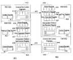
- FIG. 4is a block diagram of two Fibre Channel switches connected by a Fibre Channel link.
- FIG. 5is a block diagram of a processor-based system which may embody the present invention.
- a unique timing primitive signalmay be selected by the originating switch (“Switch 1”). This particular timing primitive signal is then written to the control register of Switch 1 [Block 304 ] and the “expected register” of Switch 1 [Block 306 ].
- the originating switchmay send the value of the selected timing primitive signal to the responding switch (“Switch 2”) at the other end of the link [Block 308 ].
- the timing signal primitive valuemay be contained in the payload of a frame sent by Switch 1 to Switch 2 .
- a frameis a data unit containing a start-of-frame (SOF) delimiter, a header, the payload, a cyclic redundancy check value (for error detection and correction) and an end-of-frame (EOF) delimiter.
- SOFstart-of-frame
- EEFend-of-frame
- Switch 2stores the value of the timing primitive signal in an “echo register” within Switch 2 [Block 310 ] for comparison to timing primitive signals subsequently received by Switch 2 .
- the echo functionmay be enabled in the responding switch (Switch 2 ) by the sending of an appropriate signal from the originating switch (Switch 1 ) [Block 312 ].
- a timer associated with the originating switchmay be cleared [Block 314 ].
- the timing primitive signalmay be sent and the timer simultaneously started [Block 316 ]
- FIG. 3 bThe actions of a switch receiving a timing primitive signal in one particular embodiment are depicted in FIG. 3 b beginning with the receipt of a timing primitive signal [Block 320 ].
- the value of the received timing primitive signalis compared to the value (if any) stored in the expected register of the switch [Diamond 322 ]. This function is associated with the action of the switch in the role of originating switch in a link round trip delay measurement. If the expected value is received [Y branch of Diamond 322 ], the timing primitive signal sent by the switch has been successfully echoed by the responding switch and the timer may be stopped [Block 324 ] and an interrupt issued [Block 326 ]
- the value of the received timing primitive signalmay be compared to the value stored in the echo register of the switch [Diamond 328 ]. If the value of the TPS matches that in the echo register [Y branch of Diamond 328 ], it is indicative of a link round trip delay measurement being conducted by an originating switch at the other end of the connecting link and the TPS may be retransmitted (“echoed”) from the receiving switch [Block 330 ] if the echo function of the switch is enabled.
- the received TPS valuemay be stored in an “unexpected ordered set register” and an interrupt may be issued [Block 334 ] to initiate error detection and recovery.
- Block 334One possible scenario leading to the event depicted in Block 332 is the corruption of a timing primitive signal during transmission.
- FIG. 3 cThe actions of a processor-based system which may comprise a switch in a Fibre Channel network in response to an interrupt signal are shown in FIG. 3 c.
- the timerwill have been stopped by the logic circuitry upon receipt of a TPS that matches the value stored in the expected register of the switch [Block 324 of FIG. 3 b ]. Accordingly, the timer may be read [Block 342 ] to determine the number of clock cycles since the timer was started (or since the timer counter rolled over).
- the timer counter registeris a binary counter having a finite number of bits. If the timer count exceeds the maximum value that the register can hold, the register “wraps”—i.e., increments to zero—and an interrupt signal may be generated. If a timer wrap occurs [Y branch of Diamond 350 ], a counter may be incremented [Block 360 ] so as to increase the effective capacity of the timer register. In such an embodiment, the wrap counter must also be read [Block 344 ] and the value of the timer register adjusted for the number of times the timer counter has wrapped [Block 346 ] before computing the link round trip delay [Block 348 ].
- a “link round trip timer invalid” interrupt request[Block 352 ] indicates that an End of Frame delimiter has been detected by the receiving logic circuitry before the expected timing primitive signal. This is an indication that the link round trip delay measurement is possibly inaccurate due to an interruption caused by a frame transmission in the middle of TPS echoing on the other side of the link [Y branch of Diamond 352 ]. In this situation, it may be desirous to restart the link round trip delay measurement [Block 370 ].
- FIG. 4One particular hardware embodiment of the present invention is shown in block diagram form in FIG. 4 wherein 401 and 402 are 10GFC ports (Fibre Channel expansion ports connecting two switches using a 10GFC link) of two Fibre Channel switches connected in a point-to-point topology. Switches are fabric devices providing full bandwidth per port and high-speed routing of data via link-level addressing. Arrows 450 denote an Interswitch Link—a bi-directional point-to-point serial data channel connection between two switches using the 10GFC ports.
- 10GFC portsFibre Channel expansion ports connecting two switches using a 10GFC link
- Switchesare fabric devices providing full bandwidth per port and high-speed routing of data via link-level addressing.
- Arrows 450denote an Interswitch Link—a bi-directional point-to-point serial data channel connection between two switches using the 10GFC ports.
- Transmitters 410 and 440comprise control registers 412 and 442 , respectively and ordered set control registers 414 and 444 , respectively.
- Receivers 420 and 430comprise control registers 421 and 431 , respectively; status registers 424 and 434 , respectively; interrupt flag registers 422 and 432 , respectively; echo registers 426 and 436 , respectively, expected registers 427 and 437 , respectively; and, unexpected ordered set receive registers 428 and 438 , respectively.
- the timing primitive signal to be transmittedis loaded into the ordered set control register 9414 and/or 444 ) of the originating switch and the TPS is transmitted and the link round trip timer is started by setting appropriate bits in the control register ( 412 and/or 442 ).
- a particular bit in the control register in the receiver logicmay be used to indicate that TPS retransmission has been enabled.
- TPS values to be echoedmay be stored in an echo register ( 426 and/or 436 ) while TPS values sent by an originating switch may be stored in the expected register ( 427 and/or 437 ) of the originating switch.
- Unexpected timing primitive signalsmay be stored in the unexpected ordered set receive register ( 428 and/or 438 ) of a responding switch and an appropriate interrupt flag written to the associated interrupt flag register ( 422 and/or 432 ).
- the receipt of a TPS matching the contents of the expected registerwill also cause the generation of an interrupt and a corresponding flag may be stored in the associated interrupt flag register ( 422 or 432 ). Determination of the interrupt source can be made by referencing the status register ( 424 and/or 434 ).
- a processor-based system which may embody the present inventionis shown in block diagram form in FIG. 5 wherein processor and I/O interface complex 502 provides the processing capabilities of the processor-based system 500 .
- the processormay be any of various suitable processors, including the Intel i 960 and the Motorola PowerPC.
- the I/O interfacesmay include low speed serial interfaces, such as RS-232, which use a driver/receiver circuit 504 , or high-speed serial network interfaces, such as Ethernet, which use a PHY circuit 506 to connect to a local area network (LAN).
- Main memory or DRAM 508 and flash or permanent memory 510are connected to the processor complex 502 to provide memory to control and be used by the processor.
- the processor complex 502also includes an I/O bus interface 512 , such as a PCI bus, to connect to Fibre Channel circuit 514 .
- the Fibre Channel circuit 514contains the Fibre Channel ports which perform the link round trip delay measurement. Each port is connected to an external SERDES circuit 518 , which in turn is connected to a media interface 520 , which receives the particular medium used to interconnect switches used to form a fabric or to connect to various devices or nodes.
- link round trip delay measurementsmay be conducted simultaneously by each switch connected by an interswitch link.
Landscapes
- Engineering & Computer Science (AREA)
- Computer Networks & Wireless Communication (AREA)
- Signal Processing (AREA)
- Environmental & Geological Engineering (AREA)
- Data Exchanges In Wide-Area Networks (AREA)
- Communication Control (AREA)
Abstract
Description
Claims (37)
Priority Applications (1)
| Application Number | Priority Date | Filing Date | Title |
|---|---|---|---|
| US10/205,793US7286527B2 (en) | 2002-07-26 | 2002-07-26 | Method and apparatus for round trip delay measurement in a bi-directional, point-to-point, serial data channel |
Applications Claiming Priority (1)
| Application Number | Priority Date | Filing Date | Title |
|---|---|---|---|
| US10/205,793US7286527B2 (en) | 2002-07-26 | 2002-07-26 | Method and apparatus for round trip delay measurement in a bi-directional, point-to-point, serial data channel |
Publications (2)
| Publication Number | Publication Date |
|---|---|
| US20040017806A1 US20040017806A1 (en) | 2004-01-29 |
| US7286527B2true US7286527B2 (en) | 2007-10-23 |
Family
ID=30770154
Family Applications (1)
| Application Number | Title | Priority Date | Filing Date |
|---|---|---|---|
| US10/205,793Expired - Fee RelatedUS7286527B2 (en) | 2002-07-26 | 2002-07-26 | Method and apparatus for round trip delay measurement in a bi-directional, point-to-point, serial data channel |
Country Status (1)
| Country | Link |
|---|---|
| US (1) | US7286527B2 (en) |
Cited By (1)
| Publication number | Priority date | Publication date | Assignee | Title |
|---|---|---|---|---|
| US20100085981A1 (en)* | 2008-10-03 | 2010-04-08 | Brocade Communications, Inc. | Port trunking at a fabric boundary |
Families Citing this family (32)
| Publication number | Priority date | Publication date | Assignee | Title |
|---|---|---|---|---|
| US7457242B2 (en)* | 2004-02-12 | 2008-11-25 | Avaya, Inc. | System for transmitting high quality speech signals on a voice over internet protocol network |
| US8151103B2 (en) | 2004-03-13 | 2012-04-03 | Adaptive Computing Enterprises, Inc. | System and method for providing object triggers |
| US8782654B2 (en) | 2004-03-13 | 2014-07-15 | Adaptive Computing Enterprises, Inc. | Co-allocating a reservation spanning different compute resources types |
| US20070266388A1 (en) | 2004-06-18 | 2007-11-15 | Cluster Resources, Inc. | System and method for providing advanced reservations in a compute environment |
| US8176490B1 (en) | 2004-08-20 | 2012-05-08 | Adaptive Computing Enterprises, Inc. | System and method of interfacing a workload manager and scheduler with an identity manager |
| WO2006053093A2 (en) | 2004-11-08 | 2006-05-18 | Cluster Resources, Inc. | System and method of providing system jobs within a compute environment |
| US7406101B1 (en)* | 2004-12-10 | 2008-07-29 | National Semiconductor Corporation | System and method for providing on-chip delay measurements in serializer / deserializer systems |
| US8863143B2 (en) | 2006-03-16 | 2014-10-14 | Adaptive Computing Enterprises, Inc. | System and method for managing a hybrid compute environment |
| US9413687B2 (en) | 2005-03-16 | 2016-08-09 | Adaptive Computing Enterprises, Inc. | Automatic workload transfer to an on-demand center |
| US9231886B2 (en) | 2005-03-16 | 2016-01-05 | Adaptive Computing Enterprises, Inc. | Simple integration of an on-demand compute environment |
| ES2614751T3 (en) | 2005-04-07 | 2017-06-01 | Iii Holdings 12, Llc | Access on demand to computer resources |
| CN100387003C (en)* | 2005-06-27 | 2008-05-07 | 华为技术有限公司 | A Detection Method of Link Delay |
| DE102007013846A1 (en)* | 2007-03-20 | 2008-09-25 | Adva Ag Optical Networking | Method for management of data transmission network, particularly dynamically reconfigurable data transmission network, involves assembling data transmission link from multiple sub-links |
| US8041773B2 (en) | 2007-09-24 | 2011-10-18 | The Research Foundation Of State University Of New York | Automatic clustering for self-organizing grids |
| US9054990B2 (en) | 2009-10-30 | 2015-06-09 | Iii Holdings 2, Llc | System and method for data center security enhancements leveraging server SOCs or server fabrics |
| US20130107444A1 (en) | 2011-10-28 | 2013-05-02 | Calxeda, Inc. | System and method for flexible storage and networking provisioning in large scalable processor installations |
| US9077654B2 (en) | 2009-10-30 | 2015-07-07 | Iii Holdings 2, Llc | System and method for data center security enhancements leveraging managed server SOCs |
| US9876735B2 (en) | 2009-10-30 | 2018-01-23 | Iii Holdings 2, Llc | Performance and power optimized computer system architectures and methods leveraging power optimized tree fabric interconnect |
| US20110103391A1 (en) | 2009-10-30 | 2011-05-05 | Smooth-Stone, Inc. C/O Barry Evans | System and method for high-performance, low-power data center interconnect fabric |
| US9465771B2 (en) | 2009-09-24 | 2016-10-11 | Iii Holdings 2, Llc | Server on a chip and node cards comprising one or more of same |
| US8599863B2 (en) | 2009-10-30 | 2013-12-03 | Calxeda, Inc. | System and method for using a multi-protocol fabric module across a distributed server interconnect fabric |
| US9680770B2 (en) | 2009-10-30 | 2017-06-13 | Iii Holdings 2, Llc | System and method for using a multi-protocol fabric module across a distributed server interconnect fabric |
| US11720290B2 (en) | 2009-10-30 | 2023-08-08 | Iii Holdings 2, Llc | Memcached server functionality in a cluster of data processing nodes |
| US10877695B2 (en) | 2009-10-30 | 2020-12-29 | Iii Holdings 2, Llc | Memcached server functionality in a cluster of data processing nodes |
| US9311269B2 (en) | 2009-10-30 | 2016-04-12 | Iii Holdings 2, Llc | Network proxy for high-performance, low-power data center interconnect fabric |
| US9648102B1 (en) | 2012-12-27 | 2017-05-09 | Iii Holdings 2, Llc | Memcached server functionality in a cluster of data processing nodes |
| US9092594B2 (en) | 2011-10-31 | 2015-07-28 | Iii Holdings 2, Llc | Node card management in a modular and large scalable server system |
| US10073751B2 (en) | 2015-11-20 | 2018-09-11 | International Business Machines Corporation | Determining cable connections in a multi-cable link |
| US9985876B2 (en)* | 2015-11-20 | 2018-05-29 | International Business Machines Corporation | Determining cable connections in a multi-cable link |
| US9992091B2 (en)* | 2015-11-30 | 2018-06-05 | Cisco Technology, Inc. | Performing network topology traces with minimal data collection |
| CN110493169A (en)* | 2018-05-14 | 2019-11-22 | 北京大学 | A kind of large-scale data package transmission method |
| US10895988B2 (en)* | 2019-04-02 | 2021-01-19 | EMC IP Holding Company LLC | Measuring latency in storage area networks |
Citations (5)
| Publication number | Priority date | Publication date | Assignee | Title |
|---|---|---|---|---|
| US5959568A (en)* | 1996-06-26 | 1999-09-28 | Par Goverment Systems Corporation | Measuring distance |
| US20020120727A1 (en)* | 2000-12-21 | 2002-08-29 | Robert Curley | Method and apparatus for providing measurement, and utilization of, network latency in transaction-based protocols |
| US20030048754A1 (en)* | 2001-09-04 | 2003-03-13 | Leon Bruckman | Latency evaluation in a ring network |
| US6751198B1 (en)* | 1999-12-27 | 2004-06-15 | Nortel Networks Limited | System and method for measuring round trip delay of voice packets in a telephone system |
| US6952419B1 (en)* | 2000-10-25 | 2005-10-04 | Sun Microsystems, Inc. | High performance transmission link and interconnect |
- 2002
- 2002-07-26USUS10/205,793patent/US7286527B2/ennot_activeExpired - Fee Related
Patent Citations (5)
| Publication number | Priority date | Publication date | Assignee | Title |
|---|---|---|---|---|
| US5959568A (en)* | 1996-06-26 | 1999-09-28 | Par Goverment Systems Corporation | Measuring distance |
| US6751198B1 (en)* | 1999-12-27 | 2004-06-15 | Nortel Networks Limited | System and method for measuring round trip delay of voice packets in a telephone system |
| US6952419B1 (en)* | 2000-10-25 | 2005-10-04 | Sun Microsystems, Inc. | High performance transmission link and interconnect |
| US20020120727A1 (en)* | 2000-12-21 | 2002-08-29 | Robert Curley | Method and apparatus for providing measurement, and utilization of, network latency in transaction-based protocols |
| US20030048754A1 (en)* | 2001-09-04 | 2003-03-13 | Leon Bruckman | Latency evaluation in a ring network |
Non-Patent Citations (2)
| Title |
|---|
| ANSI X3.272-1996 Fibre Channel-Arbitrated Loop (FC-AL) pp. 14-18 (FC-AL Primitive Signals and Sequences). |
| Fibre Channel-Physical and Signaling Interface (FC-PH) Rev 4.3 working draft Jun. 1, 1994; Ordered sets pp. 81-89; Table 25 Primitive Signals p. 71; Table 26 Primitive Sequences p. 71; Table 27 Primitive Sequence Summary p. 87. |
Cited By (2)
| Publication number | Priority date | Publication date | Assignee | Title |
|---|---|---|---|---|
| US20100085981A1 (en)* | 2008-10-03 | 2010-04-08 | Brocade Communications, Inc. | Port trunking at a fabric boundary |
| US8223633B2 (en) | 2008-10-03 | 2012-07-17 | Brocade Communications Systems, Inc. | Port trunking at a fabric boundary |
Also Published As
| Publication number | Publication date |
|---|---|
| US20040017806A1 (en) | 2004-01-29 |
Similar Documents
| Publication | Publication Date | Title |
|---|---|---|
| US7286527B2 (en) | Method and apparatus for round trip delay measurement in a bi-directional, point-to-point, serial data channel | |
| US6081523A (en) | Arrangement for transmitting packet data segments from a media access controller across multiple physical links | |
| US7103823B2 (en) | Communication between multi-processor clusters of multi-cluster computer systems | |
| US7117419B2 (en) | Reliable communication between multi-processor clusters of multi-cluster computer systems | |
| US11296807B2 (en) | Techniques to operate a time division multiplexing(TDM) media access control (MAC) | |
| US5072449A (en) | Packet framing using cyclic redundancy checking | |
| US20050034007A1 (en) | Synchronized communication between multi-processor clusters of multi-cluster computer systems | |
| US5007051A (en) | Link layer protocol and apparatus for data communication | |
| US10958504B1 (en) | Systems and methods for operations, administration and maintenance (OAM) in the physical coding sublayer (PCS) | |
| US6697366B1 (en) | Ethernet memory management system and methods for operation thereof | |
| JP2565631B2 (en) | Data frame transmission method and transmission system | |
| US8312362B1 (en) | Determining data transmission error and/or checking or confirming such error determinations | |
| JP2016530764A (en) | Link forwarding, bit error detection, and link retry using a flit bundle that is asynchronous with the link fabric packet | |
| US9065626B2 (en) | Bit error rate impact reduction | |
| US7395347B2 (en) | Communication between and within multi-processor clusters of multi-cluster computer systems | |
| US9059836B2 (en) | Word boundary lock | |
| KR20170018089A (en) | Efficient link layer retry protocol utilizing implicit acknowledgements | |
| JP2005018768A (en) | Dual port function for single port cell memory devices | |
| JP2986798B2 (en) | Data transmission control method and data communication device | |
| US8885673B2 (en) | Interleaving data packets in a packet-based communication system | |
| US6721320B1 (en) | Method and apparatus for fibre channel identification and retrieval | |
| US20130101076A1 (en) | Polarity Detection | |
| US6987761B2 (en) | Inbound data stream controller with pre-recognition of frame sequence | |
| JP2643089B2 (en) | Error detection and recovery system in parallel / serial bus | |
| EP1065831B1 (en) | Early preamble transmission |
Legal Events
| Date | Code | Title | Description |
|---|---|---|---|
| AS | Assignment | Owner name:BROCADE COMMUNICATIONS SYSTEMS, INC., TEXAS Free format text:ASSIGNMENT OF ASSIGNORS INTEREST;ASSIGNORS:YAZDY, FARID A.;MARTIN, KREG A.;REEL/FRAME:013144/0778 Effective date:20020724 | |
| AS | Assignment | Owner name:BANK OF AMERICA, N.A. AS ADMINISTRATIVE AGENT, CAL Free format text:SECURITY AGREEMENT;ASSIGNORS:BROCADE COMMUNICATIONS SYSTEMS, INC.;FOUNDRY NETWORKS, INC.;INRANGE TECHNOLOGIES CORPORATION;AND OTHERS;REEL/FRAME:022012/0204 Effective date:20081218 Owner name:BANK OF AMERICA, N.A. AS ADMINISTRATIVE AGENT,CALI Free format text:SECURITY AGREEMENT;ASSIGNORS:BROCADE COMMUNICATIONS SYSTEMS, INC.;FOUNDRY NETWORKS, INC.;INRANGE TECHNOLOGIES CORPORATION;AND OTHERS;REEL/FRAME:022012/0204 Effective date:20081218 | |
| AS | Assignment | Owner name:WELLS FARGO BANK, NATIONAL ASSOCIATION, AS COLLATE Free format text:SECURITY AGREEMENT;ASSIGNORS:BROCADE COMMUNICATIONS SYSTEMS, INC.;FOUNDRY NETWORKS, LLC;INRANGE TECHNOLOGIES CORPORATION;AND OTHERS;REEL/FRAME:023814/0587 Effective date:20100120 | |
| FPAY | Fee payment | Year of fee payment:4 | |
| AS | Assignment | Owner name:BROCADE COMMUNICATIONS SYSTEMS, INC., CALIFORNIA Free format text:RELEASE BY SECURED PARTY;ASSIGNOR:BANK OF AMERICA, N.A., AS ADMINISTRATIVE AGENT;REEL/FRAME:034792/0540 Effective date:20140114 Owner name:FOUNDRY NETWORKS, LLC, CALIFORNIA Free format text:RELEASE BY SECURED PARTY;ASSIGNOR:BANK OF AMERICA, N.A., AS ADMINISTRATIVE AGENT;REEL/FRAME:034792/0540 Effective date:20140114 Owner name:INRANGE TECHNOLOGIES CORPORATION, CALIFORNIA Free format text:RELEASE BY SECURED PARTY;ASSIGNOR:BANK OF AMERICA, N.A., AS ADMINISTRATIVE AGENT;REEL/FRAME:034792/0540 Effective date:20140114 | |
| AS | Assignment | Owner name:BROCADE COMMUNICATIONS SYSTEMS, INC., CALIFORNIA Free format text:RELEASE BY SECURED PARTY;ASSIGNOR:WELLS FARGO BANK, NATIONAL ASSOCIATION, AS COLLATERAL AGENT;REEL/FRAME:034804/0793 Effective date:20150114 Owner name:FOUNDRY NETWORKS, LLC, CALIFORNIA Free format text:RELEASE BY SECURED PARTY;ASSIGNOR:WELLS FARGO BANK, NATIONAL ASSOCIATION, AS COLLATERAL AGENT;REEL/FRAME:034804/0793 Effective date:20150114 | |
| REMI | Maintenance fee reminder mailed | ||
| LAPS | Lapse for failure to pay maintenance fees | ||
| STCH | Information on status: patent discontinuation | Free format text:PATENT EXPIRED DUE TO NONPAYMENT OF MAINTENANCE FEES UNDER 37 CFR 1.362 | |
| FP | Lapsed due to failure to pay maintenance fee | Effective date:20151023 |