US7285121B2 - Devices and methods for the correction and treatment of spinal deformities - Google Patents
Devices and methods for the correction and treatment of spinal deformitiesDownload PDFInfo
- Publication number
- US7285121B2 US7285121B2US10/137,039US13703902AUS7285121B2US 7285121 B2US7285121 B2US 7285121B2US 13703902 AUS13703902 AUS 13703902AUS 7285121 B2US7285121 B2US 7285121B2
- Authority
- US
- United States
- Prior art keywords
- bone anchor
- bone
- chamber
- head
- proximal end
- Prior art date
- Legal status (The legal status is an assumption and is not a legal conclusion. Google has not performed a legal analysis and makes no representation as to the accuracy of the status listed.)
- Expired - Lifetime, expires
Links
- 238000000034methodMethods0.000titleabstractdescription12
- 238000012937correctionMethods0.000titledescription9
- 206010058907Spinal deformityDiseases0.000titledescription5
- 210000000988bone and boneAnatomy0.000claimsdescription169
- 239000000463materialSubstances0.000claimsdescription35
- 238000003780insertionMethods0.000claimsdescription20
- 230000037431insertionEffects0.000claimsdescription20
- 230000006641stabilisationEffects0.000claimsdescription17
- 238000011105stabilizationMethods0.000claimsdescription17
- 238000004891communicationMethods0.000claimsdescription10
- 230000004927fusionEffects0.000claimsdescription8
- 230000008468bone growthEffects0.000claimsdescription5
- 238000010079rubber tappingMethods0.000claimsdescription3
- 210000001519tissueAnatomy0.000description19
- 230000006835compressionEffects0.000description11
- 238000007906compressionMethods0.000description11
- 230000033001locomotionEffects0.000description6
- 238000013459approachMethods0.000description5
- 238000003306harvestingMethods0.000description3
- 206010039722scoliosisDiseases0.000description3
- 238000001356surgical procedureMethods0.000description3
- RTAQQCXQSZGOHL-UHFFFAOYSA-NTitaniumChemical compound[Ti]RTAQQCXQSZGOHL-UHFFFAOYSA-N0.000description2
- 230000001054cortical effectEffects0.000description2
- 230000000694effectsEffects0.000description2
- 230000002708enhancing effectEffects0.000description2
- 238000011065in-situ storageMethods0.000description2
- 229910052751metalInorganic materials0.000description2
- 239000002184metalSubstances0.000description2
- 150000002739metalsChemical class0.000description2
- 238000012986modificationMethods0.000description2
- 230000004048modificationEffects0.000description2
- 229910001000nickel titaniumInorganic materials0.000description2
- 229920000642polymerPolymers0.000description2
- 229910001285shape-memory alloyInorganic materials0.000description2
- 229910001220stainless steelInorganic materials0.000description2
- 239000010935stainless steelSubstances0.000description2
- 229920002994synthetic fiberPolymers0.000description2
- 229910052719titaniumInorganic materials0.000description2
- 239000010936titaniumSubstances0.000description2
- 229910000684Cobalt-chromeInorganic materials0.000description1
- AEMRFAOFKBGASW-UHFFFAOYSA-NGlycolic acidPolymersOCC(O)=OAEMRFAOFKBGASW-UHFFFAOYSA-N0.000description1
- OUYCCCASQSFEME-QMMMGPOBSA-NL-tyrosineChemical compoundOC(=O)[C@@H](N)CC1=CC=C(O)C=C1OUYCCCASQSFEME-QMMMGPOBSA-N0.000description1
- 229920002732PolyanhydridePolymers0.000description1
- 239000004698PolyethyleneSubstances0.000description1
- 229920000954PolyglycolidePolymers0.000description1
- 229920001710PolyorthoesterPolymers0.000description1
- 229910001069Ti alloyInorganic materials0.000description1
- HZEWFHLRYVTOIW-UHFFFAOYSA-N[Ti].[Ni]Chemical compound[Ti].[Ni]HZEWFHLRYVTOIW-UHFFFAOYSA-N0.000description1
- 230000002159abnormal effectEffects0.000description1
- 229910045601alloyInorganic materials0.000description1
- 239000000956alloySubstances0.000description1
- 230000004075alterationEffects0.000description1
- 239000005313bioactive glassSubstances0.000description1
- 239000000560biocompatible materialSubstances0.000description1
- 210000002805bone matrixAnatomy0.000description1
- 229910000389calcium phosphateInorganic materials0.000description1
- 239000001506calcium phosphateSubstances0.000description1
- 235000011010calcium phosphatesNutrition0.000description1
- 239000000919ceramicSubstances0.000description1
- 239000010952cobalt-chromeSubstances0.000description1
- 239000002131composite materialSubstances0.000description1
- 210000002808connective tissueAnatomy0.000description1
- 238000002788crimpingMethods0.000description1
- 230000002939deleterious effectEffects0.000description1
- 238000005553drillingMethods0.000description1
- 238000011846endoscopic investigationMethods0.000description1
- 238000002594fluoroscopyMethods0.000description1
- 230000012010growthEffects0.000description1
- 229910052588hydroxylapatiteInorganic materials0.000description1
- 239000007943implantSubstances0.000description1
- 238000009434installationMethods0.000description1
- 210000003041ligamentAnatomy0.000description1
- 210000004705lumbosacral regionAnatomy0.000description1
- 238000002406microsurgeryMethods0.000description1
- 230000007935neutral effectEffects0.000description1
- HLXZNVUGXRDIFK-UHFFFAOYSA-Nnickel titaniumChemical compound[Ti].[Ti].[Ti].[Ti].[Ti].[Ti].[Ti].[Ti].[Ti].[Ti].[Ti].[Ni].[Ni].[Ni].[Ni].[Ni].[Ni].[Ni].[Ni].[Ni].[Ni].[Ni].[Ni].[Ni].[Ni]HLXZNVUGXRDIFK-UHFFFAOYSA-N0.000description1
- 230000035515penetrationEffects0.000description1
- XYJRXVWERLGGKC-UHFFFAOYSA-Dpentacalcium;hydroxide;triphosphateChemical compound[OH-].[Ca+2].[Ca+2].[Ca+2].[Ca+2].[Ca+2].[O-]P([O-])([O-])=O.[O-]P([O-])([O-])=O.[O-]P([O-])([O-])=OXYJRXVWERLGGKC-UHFFFAOYSA-D0.000description1
- 229920000747poly(lactic acid)Polymers0.000description1
- 239000002745poly(ortho ester)Substances0.000description1
- 229920002627poly(phosphazenes)Polymers0.000description1
- 229920000515polycarbonatePolymers0.000description1
- 239000004417polycarbonateSubstances0.000description1
- 229920000728polyesterPolymers0.000description1
- -1polyethylenePolymers0.000description1
- 229920000573polyethylenePolymers0.000description1
- 230000001737promoting effectEffects0.000description1
- 210000000954sacrococcygeal regionAnatomy0.000description1
- 239000012781shape memory materialSubstances0.000description1
- 239000007787solidSubstances0.000description1
- 239000003356suture materialSubstances0.000description1
- 210000000115thoracic cavityAnatomy0.000description1
- QORWJWZARLRLPR-UHFFFAOYSA-Htricalcium bis(phosphate)Chemical compound[Ca+2].[Ca+2].[Ca+2].[O-]P([O-])([O-])=O.[O-]P([O-])([O-])=OQORWJWZARLRLPR-UHFFFAOYSA-H0.000description1
- OUYCCCASQSFEME-UHFFFAOYSA-NtyrosineNatural productsOC(=O)C(N)CC1=CC=C(O)C=C1OUYCCCASQSFEME-UHFFFAOYSA-N0.000description1
Images


Classifications
- A—HUMAN NECESSITIES
- A61—MEDICAL OR VETERINARY SCIENCE; HYGIENE
- A61B—DIAGNOSIS; SURGERY; IDENTIFICATION
- A61B17/00—Surgical instruments, devices or methods
- A61B17/56—Surgical instruments or methods for treatment of bones or joints; Devices specially adapted therefor
- A61B17/58—Surgical instruments or methods for treatment of bones or joints; Devices specially adapted therefor for osteosynthesis, e.g. bone plates, screws or setting implements
- A61B17/68—Internal fixation devices, including fasteners and spinal fixators, even if a part thereof projects from the skin
- A61B17/70—Spinal positioners or stabilisers, e.g. stabilisers comprising fluid filler in an implant
- A61B17/7001—Screws or hooks combined with longitudinal elements which do not contact vertebrae
- A61B17/7002—Longitudinal elements, e.g. rods
- A61B17/7019—Longitudinal elements having flexible parts, or parts connected together, such that after implantation the elements can move relative to each other
- A61B17/7022—Tethers, i.e. longitudinal elements capable of transmitting tension only, e.g. straps, sutures or cables
- A—HUMAN NECESSITIES
- A61—MEDICAL OR VETERINARY SCIENCE; HYGIENE
- A61B—DIAGNOSIS; SURGERY; IDENTIFICATION
- A61B17/00—Surgical instruments, devices or methods
- A61B17/56—Surgical instruments or methods for treatment of bones or joints; Devices specially adapted therefor
- A61B17/58—Surgical instruments or methods for treatment of bones or joints; Devices specially adapted therefor for osteosynthesis, e.g. bone plates, screws or setting implements
- A61B17/68—Internal fixation devices, including fasteners and spinal fixators, even if a part thereof projects from the skin
- A61B17/70—Spinal positioners or stabilisers, e.g. stabilisers comprising fluid filler in an implant
- A61B17/7074—Tools specially adapted for spinal fixation operations other than for bone removal or filler handling
- A61B17/7083—Tools for guidance or insertion of tethers, rod-to-anchor connectors, rod-to-rod connectors, or longitudinal elements
- A—HUMAN NECESSITIES
- A61—MEDICAL OR VETERINARY SCIENCE; HYGIENE
- A61B—DIAGNOSIS; SURGERY; IDENTIFICATION
- A61B17/00—Surgical instruments, devices or methods
- A61B17/56—Surgical instruments or methods for treatment of bones or joints; Devices specially adapted therefor
- A61B17/58—Surgical instruments or methods for treatment of bones or joints; Devices specially adapted therefor for osteosynthesis, e.g. bone plates, screws or setting implements
- A61B17/68—Internal fixation devices, including fasteners and spinal fixators, even if a part thereof projects from the skin
- A61B17/84—Fasteners therefor or fasteners being internal fixation devices
- A61B17/86—Pins or screws or threaded wires; nuts therefor
- A61B17/864—Pins or screws or threaded wires; nuts therefor hollow, e.g. with socket or cannulated
- A—HUMAN NECESSITIES
- A61—MEDICAL OR VETERINARY SCIENCE; HYGIENE
- A61B—DIAGNOSIS; SURGERY; IDENTIFICATION
- A61B17/00—Surgical instruments, devices or methods
- A61B17/56—Surgical instruments or methods for treatment of bones or joints; Devices specially adapted therefor
- A61B17/58—Surgical instruments or methods for treatment of bones or joints; Devices specially adapted therefor for osteosynthesis, e.g. bone plates, screws or setting implements
- A61B17/68—Internal fixation devices, including fasteners and spinal fixators, even if a part thereof projects from the skin
- A61B17/70—Spinal positioners or stabilisers, e.g. stabilisers comprising fluid filler in an implant
- A61B17/7001—Screws or hooks combined with longitudinal elements which do not contact vertebrae
- A61B17/7002—Longitudinal elements, e.g. rods
- A61B17/7004—Longitudinal elements, e.g. rods with a cross-section which varies along its length
- A61B17/7007—Parts of the longitudinal elements, e.g. their ends, being specially adapted to fit around the screw or hook heads
- A—HUMAN NECESSITIES
- A61—MEDICAL OR VETERINARY SCIENCE; HYGIENE
- A61B—DIAGNOSIS; SURGERY; IDENTIFICATION
- A61B17/00—Surgical instruments, devices or methods
- A61B2017/00831—Material properties
- A61B2017/00867—Material properties shape memory effect
Definitions
- Such systems and devicesare available from various manufacturers to provide correction and stabilization of the spine.
- Such systems and devicescan include screws engaged to the vertebral bodies and configured for engagement with elongated rods or plates that extend along the vertebral bodies.
- Device for fusing adjacent vertebrae and artificial disc replacementare also available.
- nonoperative devices and methodssuch as bracing and observation, can be used whenever applicable.
- FIG. 1is an elevational view of a bone anchor according to one embodiment of the present invention.
- FIG. 2is a section view through line 2 - 2 of FIG. 1 .
- FIG. 3is a section view through line 3 - 3 of FIG. 1 .
- FIG. 4is a section view through line 4 - 4 of FIG. 3 .
- FIG. 5is an enlarged detail view of a portion of the bone anchor at the location indicated in FIG. 2 .
- FIG. 6is an enlarged elevational view of the bone anchor of FIG. 1 rotated 180 degrees about its central axis.
- FIG. 7is an enlarged perspective view of a cap engageable with the bone anchor of FIG. 6 .
- FIG. 8is a perspective view showing the cap of FIG. 7 engaged to the bone anchor of FIG. 6 .
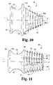
- FIG. 9is an elevational view of another embodiment bone anchor of the present invention.
- FIG. 10is an elevational view of yet another embodiment bone anchor of the present invention.
- FIG. 11is an elevational view of a further embodiment bone anchor of the present invention.
- FIG. 12is an elevational view of another embodiment bone anchor of the present invention.
- FIGS. 13 a and 13 bare anterior and lateral views, respectively, of a first step of one method for engaging the bone anchor to a vertebral body.
- FIGS. 14 a and 14 bare anterior and lateral views, respectively, of a second step of the one method for engaging the bone anchor to a vertebral body.
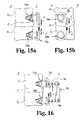
- FIGS. 15 a and 15 bare anterior and lateral views, respectively, illustrating the application of a compressive load to first and second bone anchors engaged to first and second vertebral bodies, respectively.
- FIG. 16is an anterior view illustrating the loading of a tether onto anchor extensions engaged to the first and second bone anchors of FIGS. 15 a and 15 b while compressive force is maintained on the first and second bone anchors.
- FIG. 17is an anterior view illustrating the advancement of the tether along the anchor extensions and the application of a compressive force through anchor extensions in combination with the application of the compressive force to the anchors.
- FIG. 18is an anterior view illustrating the engagement of the tether to the anchors while the compressive force on the anchors is maintained through the anchor extensions.
- FIG. 19is an anterior view illustrating the attachment of a plug to one of the bone anchors after engagement of the tether to the bone anchors.
- FIGS. 20 a and 20 bare anterior and lateral views, respectively, showing the crimping of the tether engaged to the bone anchors.
- FIGS. 21 a and 21 bare anterior and lateral views, respectively, showing an embodiment of a system of interconnecting three vertebral bodies with the bones anchors and tethers.
- FIGS. 22 a , 22 b and 22 care perspective views of an inner shaft, an outer shaft, and the assembly of the inner and outer shafts, respectively, of a tether loading instrument.
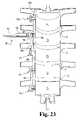
- FIG. 23is an anterior view showing one embodiment of a system of interconnecting five vertebral bodies with bone anchors and tethers along with use of the tether loading instrument of FIGS. 22 a - 22 c to load a tether on an anchor.
- FIGS. 24 a and 24 bare antero-lateral and lateral views, respectively, showing another embodiment of a system of interconnecting a segment of vertebral bodies with bones anchors and tethers.
- FIGS. 25 a and 25 bare antero-lateral and lateral views, respectively, showing yet another embodiment of a system of interconnecting a segment of vertebral bodies with bones anchors, tethers and crimps.
- the present inventionprovides anchors engageable intravertebrally to bony tissue of a vertebral body.
- the anchorsprovide solid bony attachment to the vertebra within a spinal column segment rather than between motion segments.
- the anchorshave application in, for example, the correction of spinal deformities, the temporary or permanent rigid fixation of bone, the temporary or permanent flexible fixation of bone, as a buttress for bone grafting techniques for the spine, and for fusionless scoliosis surgery.
- the anchorshave a first portion embedded into the vertebral body that can be configured to engage undisturbed bone so that the anchor is well secured to the vertebral body.
- the anchorcan be tapered and provided with a frusto-conical shape along the length of the embedded portion such that the size of the distal insertion end of the embedded portion is less than the size of the proximal end of the embedded portion.
- the frusto-conical shape of the anchorsprovides a greater margin of safety for the surgeon inserting anchor. The smaller distal end reduces the chance for the anchor to penetrate a vertebral endplate should the anchor be inserted into the vertebral body at an angle toward the endplate.
- the frusto-conical shape of the embedded portionalso provides a large surface area in contact with undisturbed bone and also a large surface area over which to distribute the anchor loads. Loading on the anchor head is more evenly distributed over the embedded portion of the anchor since the larger end of the frusto-conical portion is located adjacent the head of the anchor where the anchor load is applied.
- the anchorscan include an inner chamber and at least one opening in communication with the chamber to allow fusion of the anchor with the vertebral body.
- the embedded portion of the anchorcan further be provided with bone cutting threads and openings through which the cut bone is harvested and deposited into the chamber of the anchor.
- the chambercan extend throughout the length of the anchor to encourage undisturbed bone to enter the chamber upon initial placement into the vertebral body and to remain in continuity with the host bone.
- the chambercan also be packed with graft material alone or in combination with harvested bone.
- a cap or plugcan be engaged to the anchor to compress the harvested bone and/or graft material in the chamber of the anchor.
- the anchors described hereincan be made from any biocompatible material, including synthetic or natural autograft, allograft or xenograft tissues, and can be resorbable or non-resorbable nature.
- tissue materialsinclude hard tissues, connective tissues, demineralized bone matrix and combinations thereof.
- resorbable materialsare polylactide, polyglycolide, tyrosine-derived polycarbonate, polyanhydride, polyorthoester, polyphosphazene, calcium phosphate, hydroxyapatite, bioactive glass, and combinations thereof.
- Further examples of non-resorbable materialsare carbon-reinforced polymer composites, shape-memory alloys, titanium, titanium alloys, cobalt chrome alloys, stainless steel, ceramics and combinations thereof.
- Anchor 30includes a body 32 and a head 34 extending proximally from a proximal end 40 of body 32 .
- Body 32extends along a central longitudinal axis L distally from proximal end 40 to a distal insertion end 36 .
- Insertion end 36can be beveled to facilitate insertion of anchor 30 into bony tissue.
- a thread form 38is formed along body 32 from distal end 36 to proximal end 40 where thread form 38 runs out.
- Body 32has a frusto-conical configuration that tapers from a maximum size at proximal end 40 to a minimum size at distal end 36 .
- Thread form 38can be a continuous single thread, a series of threads, or other structure that engages bony tissue and facilitates advancement of body 32 into the vertebra, such as barbs.
- this taperforms an angle A of about 5 degrees.
- body 32can be provided with a length along axis L of between about 5 to 25 millimeters and a maximum diameter at proximal end 40 of about 10 to 20 millimeters. Other embodiments contemplate lengths and diameters outside these ranges.
- Body 32further includes a number of openings 42 formed therethrough and in communication with a chamber 44 .
- Chamber 44extends through anchor 30 and opens at the proximal end 46 of head 34 and also opens at the distal end 36 of body 32 .
- Chamber 44is also tapered at angle A, although other shapes are also contemplated.
- Chamber 44has a distal portion 44 a in body 32 and a proximal portion 44 b in head 34 .
- Openings 42interrupt thread form 38 and provide an avenue for deposit of bony tissue into chamber 44 as it is severed by thread form 38 during threaded insertion of anchor 30 into bony tissue.
- the tapered shape of body 32allows thread form 38 to engage undisturbed bone as it is inserted, and also allows body 32 to be embedded into the vertebral body in engagement with undisturbed bone. This enhances the pullout resistance capability of thread form 38 .
- two openings 42are positioned about body 32 and located along thread form 38 .
- the openings 42are spaced along thread form 38 so that at least one complete revolution of body 32 is required for the proximal opening 42 b to occupy the location previously occupied by the distal opening 42 a .
- Openings 42are also staggered about the perimeter of body 32 , thereby enhancing its structural integrity and load carrying capability.
- the opening at distal end 36provides continuity with the host bone.
- cancellous boneenters into chamber 44 through the open distal end 36 .
- This boneprovides an in situ vascularized bone graft from the host bone in chamber 44 .
- the bone harvested by thread form 38 and deposited through the openings 42provides continuity between the in situ graft and the harvested bone. Since body 32 is engaged to undisturbed bony tissue, the harvested bone remains in continuity with the undisturbed host bone.
- Openings 42are further provided with an oval shape that is centered on and extends along thread form 38 so that the bone severed by thread form 38 is deposited directly into the opening. Openings 42 are provided with a width transverse to thread form 38 sufficient to allow cut bone to be deposited therethrough into chamber 44 while minimizing the size of the openings in the wall of body 32 . In one specific embodiment, the width of openings 42 is about 2 millimeters. Other widths along body 32 for openings 42 are also contemplated.
- Thread form 38has a configuration that minimizes overlap in successive thread turns in order to minimize the disturbance to the host bone as anchor 30 is inserted while providing sufficient penetration into and engagement with undisturbed bone to provide pull-out resistance.
- axis Xis perpendicular to central longitudinal axis L.
- Thread form 38has a leading wall 48 sloped at an angle B with respect to axis X and a trailing wall slightly sloped at an angle D with respect to axis X.
- Thread form 38has a thread crest dimension C, a pitch P along body 32 , and a height H above the root diameter of body 32 .
- angle Bis about 25 degrees
- angle Dis about 5 degrees
- thread crest dimension Cis about 0.17 millimeters
- pitch Pis about 3 millimeters
- height His about 1.3 millimeters. It is also contemplated that other embodiments include other values for angle A, angle D, thread crest dimension C, pitch P and height H.
- Head 34extends from the vertebral body when body 32 is embedded therein. Head 34 can be provided with any configuration for attachment of a construct thereto for treatment or correction of a spinal condition or deformity.
- head 34has a member 52 extending proximally from proximal end 40 of body 32 .
- Member 52has a tool engaging recess 56 formed in its proximal end 46 for engagement with a driving tool, such as a screw driver, that can be used to threadingly insert body portion 32 into the vertebral body.
- Head 34further includes a lip 54 extending around and outwardly from member 52 which separates member 52 into a distal platform 52 a and a proximal platform 52 b.
- Cap 60has a stem 62 and an enlarged end member 64 .
- End member 64has a tool engaging opening 66 formed in a proximal face thereof configured to receive hex-shaped driving tool or the like.
- Stem 62can be threaded to engage threads provided in proximal portion 44 b of chamber 44 , as shown in FIG. 8 .
- end member 64is larger than head 34 and extends radially therearound when cap 60 is engaged to anchor 30 .
- end member 64is not larger than the head of the anchor. It is also contemplate that means other than threads, such as, for example, a friction or interference fit, a bayonet fit, or a snap fit, are provided to maintain cap 60 on head 34 .
- Stem 62extends distally from end member 64 , and can be provided with a length sufficient to compress harvested bone material and graft material placed in distal portion 44 a of chamber 44 when cap 60 is engaged to anchor 30 .
- the length and diameter of stem 62can be varied between different caps 60 to provide the surgeon the ability to select a stem size that provides the desired amount of compression of graft and bone tissue in chamber 44 . Compression of the harvested bone and graft material places maintains its contact with the host bone at the opening at distal end 36 and also at the openings 42 to promote fusion. Cap 60 further promotes fusion of anchor 30 to the host bone by preventing escape of the bony material from chamber 44 .
- anchor 130includes a body 132 and a head 134 extending proximally from a proximal end 140 of body 132 .
- Body 132extends along a central longitudinal axis L distally from proximal end 140 to a distal insertion end 136 .
- a thread form 138is formed along body 132 from distal end 136 to proximal end 140 where thread form 138 runs out.
- Body 132has a frusto-conical configuration that tapers from a maximum size at proximal end 140 to a minimum size at distal end 136 . In one specific embodiment, this taper forms an angle A of about 40 degrees.
- Body 132further includes a number of openings 142 formed therethrough and in communication with an internal chamber that extends through anchor 130 and opens at the proximal end 146 of head 134 and also opens at the distal end 136 of body 132 . Openings 142 interrupt thread form 138 and provide an avenue for deposit of bony tissue into the internal chamber as it is severed by thread form 138 during threaded insertion of anchor 130 into bony tissue.
- the tapered shape of body 132allows thread form 138 to at least partially engage undisturbed bone as it is inserted, and also allows body 132 to be embedded into the vertebral body in at least partial engagement with undisturbed bone. This enhances the pullout resistance capability of thread form 138 .
- openings 142 a , 142 bare positioned about body 132 and located along thread form 138 .
- Openings 142 a , 142 bare staggered about the perimeter of body 132 , thereby enhancing its structural integrity and load carrying capability.
- Openings 142 a , 142 bare further provided with a triangular shape extending along thread form 138 with the apex of the triangular opening oriented distally and the base oriented proximally.
- Openings 142 a , 142 boverlap one another along the length of body 132 .
- the leading edge of each opening 142can be undercut through the wall of body 132 so that the threads and outer surface of body 132 form a cutting edge that extends along each opening to provide aggressive bone cutting and collection through each opening.
- Head 134extends from the vertebral body when body 132 is embedded therein. As described further below, head 134 can be provided with any configuration for attachment of a construct thereto for treatment or correction of a spinal condition or deformity. In the illustrated embodiment of FIG. 9 , head 134 has a member 152 extending proximally from proximal end 140 of body 132 . Member 152 can be provided with a tool engaging recess in its proximal end 146 for engagement with a driving tool used to threadingly insert body portion 132 into the vertebral body.
- Member 152has a concave arc shape between proximal end 140 of body 132 and a lip 154 extending around and outwardly from member 152 , providing a smooth platform for connection of a construct to anchor 130 .
- the platform having a smooth arc shapereduces frictional wear on the construct engaged thereto.
- a plug or cap, such as cap 60can be secured to head 134 .
- the plug, such as plug 84 ( FIG. 19 )can be provided without an enlarged head since lip 154 can maintain the construct on the platform of member 152 .
- anchor 230includes a body 232 and a head 234 extending proximally from a proximal end 240 of body 232 .
- Body 232extends along a central longitudinal axis L distally from proximal end 240 to a distal insertion end 236 .
- Proximal end 240includes a ring shape extending radially about body 232 , acting as an abutment or stop member against the vertebral body as anchor 230 is threaded therein.
- a thread form 238is formed along body 232 from distal end 236 to proximal end 240 where thread form 238 runs out.
- Body 232has a frusto-conical configuration that tapers from a maximum size at proximal end 240 to a minimum size at distal end 236 . In one specific embodiment, this taper forms an angle A of about 45 degrees.
- Body 232further includes a number of openings 242 formed therethrough and in communication with an internal chamber that extends through anchor 230 and opens at the proximal end 246 of head 234 and also opens at the distal end 236 of body 232 . Openings 242 interrupt thread form 238 and provide an avenue for deposit of bony tissue into the internal chamber as it is severed by thread form 238 during threaded insertion of anchor 230 into bony tissue.
- the tapered shape of body 232allows thread form 238 to at least partially engage undisturbed bone as it is inserted, and also allows body 232 to be embedded into the vertebral body in at least partial engagement with undisturbed bone. This enhances the pullout resistance capability of thread form 238 .
- openings 242 a , 242 bare positioned about body 232 and located along thread form 238 .
- Openings 242 a , 242 bare staggered about the perimeter of body 232 , and are also staggered along the length of body 232 so that they do not overlap.
- Openings 242 a , 242 bare further provided with a triangular shape extending along thread form 238 with the apex of the triangular opening oriented distally and the base oriented proximally. The leading edge of the openings can be undercut to facilitate cutting and harvesting of bone.
- Head 234extends from the vertebral body when body 232 is embedded therein. As described further below, head 234 can be provided with any configuration for attachment of a construct thereto for treatment or correction of a spinal condition or deformity.
- head 234has a member 252 extending proximally from proximal end 240 of body 232 .
- Member 252can be provided with a tool engaging recess in its proximal end 246 for engagement with a driving tool used to threadingly insert body portion 232 into the vertebral body.
- Member 252has a concave arc shape between proximal end 240 of body 232 and a lip 254 extending around and outwardly from member 252 , providing a platform for connection of a construct to anchor 230 .
- anchor 330includes a body 332 and a head 334 extending proximally from a proximal end 340 of body 332 .
- Body 332extends along a central longitudinal axis L distally from proximal end 340 to a distal insertion end 336 .
- a thread form 338is formed along body 332 from distal end 336 to proximal end 340 where thread form 338 runs out.
- Body 332has a frusto-conical configuration that tapers from a maximum size at proximal end 340 to a minimum size at distal end 336 . In one specific embodiment, this taper forms an angle A of about 20 degrees.
- Body 332further includes an opening 342 formed therethrough and in communication with an internal chamber 344 .
- Chamber 344extends through anchor 330 and opens at the proximal end 346 of head 334 and also opens at the distal end 336 of body 332 .
- Opening 342has a triangular shape that interrupts thread form 338 and provides an avenue for deposit of bony tissue into the internal chamber as it is severed by thread form 338 during threaded insertion of anchor 330 into bony tissue.
- the tapered shape of body 332allows thread form 338 to at least partially engage undisturbed bone as it is inserted, and also allows body 332 to be embedded into the vertebral body in at least partial engagement with undisturbed bone. This enhances the pullout resistance capability of thread form 338 .
- opening 342extends along a substantial portion of thread form 338 maximizing its opening area for deposit of severed bony tissue.
- a leading edge of opening 342can be undercut to facilitate bone harvesting and collection.
- a number of apertures 348are provided between the crests of thread form 338 on opposite sides of body 332 . Apertures 348 provide additional avenues for bone growth for fusion of anchor 330 to the vertebral body.
- Head 334extends from the vertebral body when body 332 is embedded in the vertebral body. As described further below, head 334 can be provided with any configuration for attachment of a construct thereto for treatment or correction of a spinal condition or deformity.
- head 334has a member 352 extending proximally from proximal end 340 of body 332 .
- Member 352can be provided with a tool engaging recess in its proximal end 346 for engagement with a driving tool used to threadingly insert body portion 332 into the vertebral body.
- Member 352has a concave arc shape between proximal end 340 of body 332 and a lip 354 extending around and outwardly from member 352 , providing a platform for connection of a construct to anchor 330 .
- anchor 430includes a body 432 and a head 434 extending proximally from a proximal end 440 of body 432 .
- Body 432extends along a central longitudinal axis L distally from proximal end 440 to a distal insertion end 436 .
- a thread form 438is formed along body 432 from distal end 436 to proximal end 440 where thread form 438 runs out.
- Body 432has a frusto-conical configuration that tapers from a maximum size at proximal end 440 to a minimum size at distal end 436 . In one specific embodiment, this taper forms an angle A of about 10 degrees.
- Body 432further includes an opening 442 formed therethrough and in communication with an internal chamber 444 .
- Chamber 444extends through anchor 430 and opens at the proximal end 446 of head 434 and also opens at the distal end 436 of body 432 .
- Opening 442has a rectangular shape and interrupts thread form 438 and provides an avenue for deposit of bony tissue into the internal chamber as it is severed by thread form 438 during threaded insertion of anchor 430 into bony tissue.
- the tapered shape of body 432allows thread form 438 to at least partially engage undisturbed bone as it is inserted, and also allows body 432 to be embedded into the vertebral body in at least partial engagement with undisturbed bone. This enhances the pullout resistance capability of thread form 438 .
- opening 442extends along a substantial portion of thread form 438 to maximize its opening area for deposit of severed bony tissue.
- the leading edge of opening 442can be undercut to facilitate bone harvesting and collection.
- a number of apertures 448are provided between the crests of thread form 438 on opposite sides of body 432 . Apertures 448 provide an additional avenue for bone growth for fusion of anchor 430 to the vertebral body.
- Head 434extends from the vertebral body when body 432 is embedded in the vertebral body. As described further below, head 434 can be provided with any configuration for attachment of a construct thereto for treatment or correction of a spinal condition or deformity.
- head 434has a member 452 extending proximally from proximal end 440 of body 432 .
- Member 452can be provided with a tool engaging recess in its proximal end 446 for engagement with a driving tool used to threadingly insert body portion 432 into the vertebral body.
- Member 452has a concave arc shape between proximal end 440 of body 432 and a lip 454 extending around and outwardly from member 452 , providing a platform for connection of a construct to anchor 430 .
- FIGS. 13 a - 13 b and 14 a - 14 bOne example of an endoscopic approach for engaging an anchor to a vertebral body will be described with reference to FIGS. 13 a - 13 b and 14 a - 14 b .
- vertebral body V 1has been accessed via an endoscopic approach below segmental vessels S.
- Access tube 90is placed at the desired location relative to vertebra V 1 , and a small starting hole H is formed through tube 90 .
- Hole Hextends through the cortical bone of vertebra V 1 with minimal removal of cancellous bone.
- hole His formed in left side L of vertebra V 1 .
- access tube 90could be located so that hole H could be formed on right side R, anterior side A, posterior side P, or any other desired location on vertebra V 1 . It is also contemplated that hole H could be formed with an open surgical technique for accessing vertebrae V 1 .
- Hole His sized such that it is slightly larger than the distal end of anchor 30 .
- an anchorsuch as anchor 30
- anchor 30 and thread form 38can be self-drilling and self-tapping such that hole need not be drilled or tapped for insertion of anchor 30 .
- guidewiresare not required for insertion of anchor 30 , and that insertion can be monitored with a minimal requirements for fluoroscopy.
- Cortical bone at opening H and cancellous bone in vertebra V 1are harvested by the threads of anchor 30 and deposited into its chamber during insertion. Additional graft material or bone growth material can be placed into the chamber of anchor 30 to completely fill chamber 30 .
- Access tube 90can be repositioned relative to vertebra V 1 or over a second vertebra for insertion of one or more additional anchors 30 .
- Constructscan be used to treat a spinal deformity or condition by engaging at least one construct to one or more anchors engaged to one or more vertebrae.
- a wide variety of surgical approaches and techniques for accessing the spinal columnmay be used in securing anchors to vertebral bodies and connecting the constructs to the anchors. Such techniques include open surgical techniques in which skin and tissue are retracted to expose the spinal column and minimally invasive endoscopic techniques, including micro-surgery.
- the surgical approachmay also be any one or combination of anterior, lateral, posterior, postero-lateral, or antero-lateral approaches employing either open, endoscopic, or microscopic procedures and combinations thereof. It is further contemplated that constructs could be secured to any portion of the spinal column, including the cervical, thoracic, lumbar and sacral regions.
- the anchors described hereincan be used for the correction or treatment of a spinal deformity or condition through attachment of a stabilization construct to one or more vertebrae along the affected segment of the spinal column. It is contemplated that the anchors can be attached to tethering constructs, plate constructs and/or rod constructs to one or more vertebrae. Examples of such constructs include, but are not limited to, staples, cables, artificial strands, rods, plates, springs, artificial ligaments, and combinations thereof. Such constructs can be rigid, semi-rigid, flexible, partially flexible, resorbable, non-resorbable, superelastic, or include shape-memory material.
- Tether materialcan include but is not limited to polymers, such as polyester and polyethylene; superelastic metals, such as nitinol; shape memory alloy, such as nickel titanium; resorbable synthetic materials, such as suture material, metals, such as stainless steel and titanium; synthetic materials, allograft material; and bioelastomer material.
- one or more plate, rod or tethering constructscan be connected to the anchors using constrained, unconstrained, semi-constrained connections or combinations thereof.
- the connectioncould be unconstrained so that the construct could be allowed to slide relative to the anchor.
- An example of a semi-constrained connectionis a ball joint that allows at least some range of articulation of the construct relative to the anchor, or float within a neutral zone.
- Examples of constrained or semi-constrained connectionsinclude a construct that is wrapped around, crimped, clamped or penetrated by a portion of the anchor or a set screw or cap engageable to the anchor. Such constrained connections fix the construct to the anchor so that there is no or minimal relative movement therebetween.
- the constructcan have either a fixed length between anchors or a variable length, or combinations of fixed and variable lengths between anchors.
- Such fixed and/or variable length constructscan be provided with any combination of constrained, semi-constrained, or unconstrained connections with each anchor.
- fusionless treatment of scoliosisis provided by attaching a tethering construct to anchors engaged to the vertebral bodies on the convex side of the spine.
- the tethering constructcan correct, arrest or at least minimize growth on the convex or “long” side of the spine, thereby allowing the concave or “short” side of the spine to grow and catch up with the long side.
- fusionless tetheringmay treat abnormal spinal alignment by simply preventing further misalignment such as curve progression.
- anchorssuch as anchors 130 a and 130 b described above, have been engaged to vertebrae V 1 and V 2 , respectively, of a spinal column segment having scoliatic curvature. It is contemplated that any of the anchor embodiments described herein could be engaged to vertebrae V 1 and V 2 . It is further contemplated that the installation of anchors and tethers can be performed either endoscopically or non-endoscopically.
- a compression device 70 ais coupled to the heads of anchors 130 a , 130 b , and a compressive force is applied to the anchors as indicated by arrows F to obtain the desired corrective forces.
- anchor extensions 74 a , 74 bare elongated rods that can be securely positioned in the anchors and extend proximally therefrom.
- a tethering construct in the form a flexible loop tether 80can be placed around the proximal ends of anchor extensions 74 a , 74 b while compression is maintained with compression device 70 a .
- Other types of tethering constructsare also contemplated, such as, for example, tethers that are looped at opposite ends.
- Tether 80is then advanced distally along anchor extensions 74 a , 74 b until it is adjacent compression device 70 a as shown in FIG. 17 .
- a second compression device 70 bis coupled to the proximal ends of anchor extensions 74 a , 74 b .
- the desired corrective compressive forceis applied to anchors 130 a , 130 b through anchor extensions 74 a , 74 b with second compression device 70 b.
- first compression device 70 acan then be removed.
- Tether 80is advanced distally off of anchor extensions 74 a , 74 b and onto the platforms of the heads of anchors 130 a , 130 b .
- the attachment locations for tether 80 on the heads of the anchors 130 a , 130 bare spaced farther apart than anchor extensions 74 a , 74 b , causing tether 80 to further stretch and apply the desired compressive force to anchors 130 a , 130 b when loaded thereon.
- Second compression device 70 b and anchor extensions 74 a , 74can then be removed, and tether 80 maintains anchors 130 a , 130 b in compression, as shown in FIG. 19 .
- the grooved platform of anchor 130can be larger than the cross-sectional dimension of tether 80 such that it can hold tether 80 on anchor 130 without cap to prevent dislodgement. It is also contemplated that the grooved platform can be large enough to accommodate a pair of tethers 80 to link more than two anchors to a middle anchor. Additional bone graft can be placed into the chamber of anchors 130 a , 130 b through the proximal end opening. A cap, such as cap 60 described above, or a plug 84 can be engaged to anchors 130 a , 130 b and extend into the chamber to compress the graft material and harvested bone in the anchors.
- a flexible tether 80preserves multiple planes of motion of the vertebrae without compromising the stabilization effect. Further, flexible tether 80 can slide with respect to the head of the anchor without compromising the stabilization effect between motion segments. A flexible tether 80 also produces less deleterious effects on spinal disc D since some range of segmental motion is preserved.
- the non-rigid attachment of the tether to the anchorprotects the anchor since less forces are delivered to the anchor than would be delivered with a rigid attachment.
- the tetheris also protected from high stresses at the point of attachment since the forces are distributed over the head of the anchor rather than concentrated at a fixed point on the tether.
- the flexible tethercan also assume gradual changes in direction of the tether while minimizing stress points on the tether and the anchor, and minimizing friction and wear between the tether and the anchor.
- crimpscan be placed around tether 80 to supply additional compressive forces between anchors 130 a , 130 b .
- there is a first crimp 86 a adjacent anchor 130 athere is a second crimp 86 b adjacent anchor 130 b , and a third crimp 86 c between first crimp 86 a and second crimp 86 b .
- Crimps 86tighten tether 80 by moving the first and second portions of the tether extending along the vertebrae toward one another, thereby increasing its tension to supply additional corrective compressive force to anchors 130 a , 130 b . It is contemplated that less than three crimps or more than three crimps could be used depending on the desired corrective force to be applied to anchors 130 a , 130 b.
- Crimps 86can be in the form a loop that is pre-positioned around the middle of tether 80 before it is loaded onto anchors 130 a , 130 b , and then moved along the loaded tether 80 towards the anchors to supply additional compressive forces. Crimps 86 can also be provided in an un-looped form, and wrapped around the loaded tether 80 and secured in looped form to supply the desired compressive forces. Crimps 86 can be placed endoscopically along with tether 80 or through an open procedure.
- Crimps 86 that are in the form of loopscan have a circular, oval, rectangular, or any other shape that will extend around tether 80 .
- Crimps 86can be made from flexible or semi-rigid material that will maintain its position with respect to tether 80 when placed therearound unless forcibly moved or removed.
- the diameter of the crimp and its width W along tether 80can be selected to provide the desired amount of tension to tether 80 when crimp 86 is placed therearound.
- Crimps 86also tighten the tether around the head of the anchor to reduce the risk of dislodgement of the tether.
- a system of anchors 130 a , 130 b , 130 c , 130 d , 130 e , 130 fare engaged to vertebrae V 1 , V 2 , V 3 as shown.
- Tetheringis provided across each of the spinal discs D between adjacent vertebrae.
- tether 80 ais connected to anchors 130 b and 130 c of vertebrae V 1 and V 2 , respectively.
- Tether 80 bis connected to anchors 130 d and 130 e of vertebrae V 2 and V 3 , respectively. Tethering is not provided between anchors engaged to the same vertebral body.
- segmental vessel Scan be preserved while the desired corrective compressive forces are applied across the motion segments of the vertebrae. It is also contemplated that segmental vessels S can be ligated and tethers extend between each pair of adjacent anchors. It is further contemplated that only a single anchor can be engaged to each vertebral body, and that each anchor is tethered to anchors of the adjacent vertebral bodies.
- Loading instrument 90for loading a tether onto an anchor engaged to a vertebra.
- Loading instrument 90includes an inner shaft 92 ( FIG. 22 a ) and an outer shaft 94 ( FIG. 22 b .)
- Outer shaft 94is slidably mounted on inner shaft 92 ( FIG. 22 c ), and outer shaft 94 is movable along inner shaft 92 by actuating a handle (not shown) connected at the proximal ends of the inner and outer shafts.
- the handlecan be a Kerrison-type handle or other suitable device for moving outer shaft 94 relative to inner shaft 92 .
- Inner shaft 92has a distal end 98 that includes a scalloped surface 100 and a tether staging surface 102 opposite scalloped surface 100 .
- Inner shaft 92has a distal protrusion 96 extending distally therefrom that is positionable into the proximal end opening of the anchor.
- Outer shaft 94has a tether engaging member 104 at its distal end that is positioned around distal end 98 of inner shaft 92 adjacent tether staging surface 102 .
- Tether 80 bis placed around anchor 30 c , and the distal end of inner shaft 92 is placed through the upper end of tether 80 b with scalloped surface 100 oriented upwardly (opposite that shown in FIG. 23 .)
- Protrusion 96is positioned in the proximal end opening of anchor 30 b .
- Loading instrument 90is rotated 180 degrees about its longitudinal axis with protrusion 96 in anchor 30 b so that tether 80 b is positioned on tether staging surface 102 .
- Tether staging surface 102is generally aligned with the upper surface of the platform defined by the head of anchor 30 b .
- Outer shaft 94is then moved distally in the direction of arrow T with respect to inner shaft 92 so that the distal end of tether engaging member 104 contacts tether 80 b and pushes it distally along inner shaft 92 and onto the head of anchor 30 b.
- anchors 30 a , 30 b , 30 c , 30 d , 30 eare engaged to vertebrae V 1 , V 2 , V 3 , V 4 , V 5 , respectively.
- Tether 80 ais engaged to the distal platforms of anchors 30 a , 30 b and tether 80 c is engaged to the distal platforms of anchors 30 c , 30 d .
- Tether 80 bis engaged to the proximal platforms of anchors 30 b , 30 c and tether 80 d is engaged to the proximal platforms of anchors 30 d , 30 e .
- Caps 60are engaged to respective ones of the anchors to compress and maintain the graft material in the anchors and to secure the tethers on the anchors.
- FIGS. 25 a - 25 bthere is shown the system of FIGS. 24 a - 24 b with crimped tethers.
- Crimp 86 ais placed around tether 80 a
- crimp 86 bis placed around tether 80 b
- crimp 86 cis placed around tether 80 c
- crimp 86 dis placed around tether 80 d .
- additional crimpscan be placed around the tethers as desired to increase the corrective compressive force on the anchors.
- crimps 86can be pre-loaded on tethers 80 before attachment to anchors 80 or configured to be attached to tethers 80 after tethers 80 are engaged to the anchors.
Landscapes
- Health & Medical Sciences (AREA)
- Orthopedic Medicine & Surgery (AREA)
- Life Sciences & Earth Sciences (AREA)
- Neurology (AREA)
- Surgery (AREA)
- Heart & Thoracic Surgery (AREA)
- Engineering & Computer Science (AREA)
- Biomedical Technology (AREA)
- Nuclear Medicine, Radiotherapy & Molecular Imaging (AREA)
- Medical Informatics (AREA)
- Molecular Biology (AREA)
- Animal Behavior & Ethology (AREA)
- General Health & Medical Sciences (AREA)
- Public Health (AREA)
- Veterinary Medicine (AREA)
- Prostheses (AREA)
- Surgical Instruments (AREA)
Abstract
Description
Claims (61)
Priority Applications (1)
| Application Number | Priority Date | Filing Date | Title |
|---|---|---|---|
| US10/137,039US7285121B2 (en) | 2001-11-05 | 2002-05-02 | Devices and methods for the correction and treatment of spinal deformities |
Applications Claiming Priority (2)
| Application Number | Priority Date | Filing Date | Title |
|---|---|---|---|
| US33793701P | 2001-11-05 | 2001-11-05 | |
| US10/137,039US7285121B2 (en) | 2001-11-05 | 2002-05-02 | Devices and methods for the correction and treatment of spinal deformities |
Publications (2)
| Publication Number | Publication Date |
|---|---|
| US20030088251A1 US20030088251A1 (en) | 2003-05-08 |
| US7285121B2true US7285121B2 (en) | 2007-10-23 |
Family
ID=23322667
Family Applications (1)
| Application Number | Title | Priority Date | Filing Date |
|---|---|---|---|
| US10/137,039Expired - LifetimeUS7285121B2 (en) | 2001-11-05 | 2002-05-02 | Devices and methods for the correction and treatment of spinal deformities |
Country Status (6)
| Country | Link |
|---|---|
| US (1) | US7285121B2 (en) |
| EP (1) | EP1450703A4 (en) |
| JP (1) | JP2005507726A (en) |
| AU (2) | AU2002330174B2 (en) |
| CA (1) | CA2465982A1 (en) |
| WO (1) | WO2003039330A2 (en) |
Cited By (57)
| Publication number | Priority date | Publication date | Assignee | Title |
|---|---|---|---|---|
| US20050197662A1 (en)* | 2000-08-28 | 2005-09-08 | Ron Clark | Method and implant for securing ligament replacement into the knee |
| US20060149264A1 (en)* | 2004-12-20 | 2006-07-06 | Castaneda Javier E | Screw locking systems for bone plates |
| US20060271050A1 (en)* | 2005-03-30 | 2006-11-30 | Gabriel Piza Vallespir | Instrumentation and methods for reducing spinal deformities |
| US20070288024A1 (en)* | 2006-06-06 | 2007-12-13 | Sohrab Gollogly | Bone fixation |
| US20080275553A1 (en)* | 2006-11-09 | 2008-11-06 | Wolf Alan W | External bullet anchor apparatus and method for use in surgical repair of ligament or tendon |
| US20090170617A1 (en)* | 2003-08-04 | 2009-07-02 | Neil Walter Lindh Adcock | Tap and a method of tapping |
| USD595855S1 (en) | 2008-11-25 | 2009-07-07 | Orthopedic Development Corporation | Bone plug |
| US7591850B2 (en) | 2005-04-01 | 2009-09-22 | Arthrocare Corporation | Surgical methods for anchoring and implanting tissues |
| US20100114317A1 (en)* | 2007-09-07 | 2010-05-06 | Intrinsic Therapeutics, Inc. | Impaction grafting for vertebral fusion |
| US7713293B2 (en) | 2002-04-16 | 2010-05-11 | Arthrocare Corporation | Transverse suspension device |
| US7815663B2 (en)* | 2006-01-27 | 2010-10-19 | Warsaw Orthopedic, Inc. | Vertebral rods and methods of use |
| US7837718B2 (en) | 2000-08-28 | 2010-11-23 | Biomet Sports Medicine, Llc | Method and implant for securing ligament replacement into the knee |
| US7896917B2 (en) | 2003-10-15 | 2011-03-01 | Biomet Sports Medicine, Llc | Method and apparatus for graft fixation |
| US20110106165A1 (en)* | 2009-10-30 | 2011-05-05 | Warsaw Orthopedic, Inc. | Devices and methods for dynamic spinal stabilization and correction of spinal deformities |
| US7959679B2 (en) | 1999-08-18 | 2011-06-14 | Intrinsic Therapeutics, Inc. | Intervertebral anulus and nucleus augmentation |
| US7972337B2 (en) | 2005-12-28 | 2011-07-05 | Intrinsic Therapeutics, Inc. | Devices and methods for bone anchoring |
| US8002778B1 (en)* | 2004-06-28 | 2011-08-23 | Biomet Sports Medicine, Llc | Crosspin and method for inserting the same during soft ligament repair |
| US8002836B2 (en) | 1999-08-18 | 2011-08-23 | Intrinsic Therapeutics, Inc. | Method for the treatment of the intervertebral disc anulus |
| US8021425B2 (en)* | 1999-08-18 | 2011-09-20 | Intrinsic Therapeutics, Inc. | Versatile method of repairing an intervertebral disc |
| US20120035671A1 (en)* | 2010-04-18 | 2012-02-09 | Advanced Bone Anchor, Llc | Internal Joint Bracing System and Suture Anchoring Assembly Therefore |
| US8118840B2 (en) | 2009-02-27 | 2012-02-21 | Warsaw Orthopedic, Inc. | Vertebral rod and related method of manufacture |
| US8147546B2 (en) | 2007-03-13 | 2012-04-03 | Biomet Sports Medicine, Llc | Method and apparatus for graft fixation |
| US8231678B2 (en) | 1999-08-18 | 2012-07-31 | Intrinsic Therapeutics, Inc. | Method of treating a herniated disc |
| US8231659B2 (en) | 2010-07-30 | 2012-07-31 | Warsaw Orthopedic | Anchoring mechanism |
| US20120310282A1 (en)* | 2008-07-05 | 2012-12-06 | Abdou M Samy | Device and method for the prevention of multi-level vertebral extension |
| US8328807B2 (en) | 2008-07-09 | 2012-12-11 | Icon Orthopaedic Concepts, Llc | Ankle arthrodesis nail and outrigger assembly |
| US8414584B2 (en) | 2008-07-09 | 2013-04-09 | Icon Orthopaedic Concepts, Llc | Ankle arthrodesis nail and outrigger assembly |
| US8449612B2 (en) | 2009-11-16 | 2013-05-28 | Arthrocare Corporation | Graft pulley and methods of use |
| US8454612B2 (en) | 2007-09-07 | 2013-06-04 | Intrinsic Therapeutics, Inc. | Method for vertebral endplate reconstruction |
| US20130211454A1 (en)* | 2010-09-20 | 2013-08-15 | Aesculap Ag | Spinal column stabilization system and surgical device for temporarily stiffening a flexible intermediate section of a connecting element of the spinal column stabilization system |
| US8821557B2 (en) | 2003-06-13 | 2014-09-02 | Covidien Lp | Surgical fastener with predetermined resorption rate |
| US9011494B2 (en) | 2009-09-24 | 2015-04-21 | Warsaw Orthopedic, Inc. | Composite vertebral rod system and methods of use |
| US20150142058A1 (en)* | 2012-06-18 | 2015-05-21 | Bruce Francis Hodgson | Method and apparatus for the treatment of scoliosis |
| US9072554B2 (en) | 2005-09-21 | 2015-07-07 | Children's Hospital Medical Center | Orthopedic implant |
| US9675386B2 (en) | 2013-03-11 | 2017-06-13 | K2M, Inc. | Flexible fastening system |
| US20170181771A1 (en)* | 2012-06-18 | 2017-06-29 | Bruce Francis Hodgson | Method and apparatus for the treatment of scoliosis |
| US9706947B2 (en) | 1999-08-18 | 2017-07-18 | Intrinsic Therapeutics, Inc. | Method of performing an anchor implantation procedure within a disc |
| US9795421B2 (en) | 2015-07-07 | 2017-10-24 | K2M, Inc. | Spinal construct with flexible member |
| US10543107B2 (en) | 2009-12-07 | 2020-01-28 | Samy Abdou | Devices and methods for minimally invasive spinal stabilization and instrumentation |
| US10548740B1 (en) | 2016-10-25 | 2020-02-04 | Samy Abdou | Devices and methods for vertebral bone realignment |
| US10575961B1 (en) | 2011-09-23 | 2020-03-03 | Samy Abdou | Spinal fixation devices and methods of use |
| US10695105B2 (en) | 2012-08-28 | 2020-06-30 | Samy Abdou | Spinal fixation devices and methods of use |
| US20200360059A1 (en)* | 2018-01-30 | 2020-11-19 | Orthopediatrics Corp. | Segmental tensioning of spinal tethers |
| US10857003B1 (en) | 2015-10-14 | 2020-12-08 | Samy Abdou | Devices and methods for vertebral stabilization |
| US10918498B2 (en) | 2004-11-24 | 2021-02-16 | Samy Abdou | Devices and methods for inter-vertebral orthopedic device placement |
| US10973648B1 (en) | 2016-10-25 | 2021-04-13 | Samy Abdou | Devices and methods for vertebral bone realignment |
| US11006982B2 (en) | 2012-02-22 | 2021-05-18 | Samy Abdou | Spinous process fixation devices and methods of use |
| US11173040B2 (en) | 2012-10-22 | 2021-11-16 | Cogent Spine, LLC | Devices and methods for spinal stabilization and instrumentation |
| US11179248B2 (en) | 2018-10-02 | 2021-11-23 | Samy Abdou | Devices and methods for spinal implantation |
| US11185353B2 (en) | 2018-03-22 | 2021-11-30 | Orthopediatrics Corp. | Anchors for vertebral body |
| US11246636B2 (en) | 2019-04-26 | 2022-02-15 | Braunvest Llc | Systems, methods, and apparatus for spinal deformity correction |
| US11648000B2 (en) | 2018-07-30 | 2023-05-16 | Braunvest Llc | Vertebral probes and related surgical methods |
| US20230329757A1 (en)* | 2020-12-17 | 2023-10-19 | Institute For Spine & Scoliosis, P.A. | Method for improved spinal correction surgery implementing non-fusion anterior scoliosis correction techniques |
| US12121269B2 (en) | 2016-10-11 | 2024-10-22 | K2M, Inc. | Spinal implant and methods of use thereof |
| US12232781B2 (en) | 2018-07-30 | 2025-02-25 | BraunVest, LLC | Cortical/cancellous bone probes and related surgical methods |
| US12329429B2 (en) | 2019-04-26 | 2025-06-17 | Braunvest Llc | Systems, methods, and apparatus for spinal deformity correction |
| US12419670B2 (en) | 2019-04-26 | 2025-09-23 | BraunVest, LLC | Methods for bone compression and/or fixation |
Families Citing this family (179)
| Publication number | Priority date | Publication date | Assignee | Title |
|---|---|---|---|---|
| US6969610B2 (en)* | 2001-01-12 | 2005-11-29 | University Of Rochester | Methods of modifying cell structure and remodeling tissue |
| FR2823095B1 (en)* | 2001-04-06 | 2004-02-06 | Ldr Medical | RACHIS OSTEOSYNTHESIS DEVICE AND PLACEMENT METHOD |
| FR2831049B1 (en)* | 2001-10-18 | 2004-08-13 | Ldr Medical | PLATE FOR OSTEOSYNTHESIS DEVICE AND PRE-ASSEMBLY METHOD |
| FR2831048B1 (en)* | 2001-10-18 | 2004-09-17 | Ldr Medical | PROGRESSIVE APPROACH OSTEOSYNTHESIS DEVICE AND PRE-ASSEMBLY PROCESS |
| FR2833151B1 (en) | 2001-12-12 | 2004-09-17 | Ldr Medical | BONE ANCHORING IMPLANT WITH POLYAXIAL HEAD |
| JP2005169064A (en)* | 2003-05-22 | 2005-06-30 | Sohei Ebara | Surgical device for correction of spinal deformity, and method for using the same |
| FR2859095B1 (en) | 2003-09-01 | 2006-05-12 | Ldr Medical | BONE ANCHORING IMPLANT WITH A POLYAXIAL HEAD AND METHOD OF PLACING THE IMPLANT |
| US7763052B2 (en)* | 2003-12-05 | 2010-07-27 | N Spine, Inc. | Method and apparatus for flexible fixation of a spine |
| US20050203513A1 (en)* | 2003-09-24 | 2005-09-15 | Tae-Ahn Jahng | Spinal stabilization device |
| US8979900B2 (en) | 2003-09-24 | 2015-03-17 | DePuy Synthes Products, LLC | Spinal stabilization device |
| US7137985B2 (en)* | 2003-09-24 | 2006-11-21 | N Spine, Inc. | Marking and guidance method and system for flexible fixation of a spine |
| US7815665B2 (en)* | 2003-09-24 | 2010-10-19 | N Spine, Inc. | Adjustable spinal stabilization system |
| US7608092B1 (en) | 2004-02-20 | 2009-10-27 | Biomet Sports Medicince, LLC | Method and apparatus for performing meniscus repair |
| DE102004009429A1 (en)* | 2004-02-24 | 2005-09-22 | Biedermann Motech Gmbh | Bone anchoring element |
| US8523904B2 (en) | 2004-03-09 | 2013-09-03 | The Board Of Trustees Of The Leland Stanford Junior University | Methods and systems for constraint of spinous processes with attachment |
| US7458981B2 (en) | 2004-03-09 | 2008-12-02 | The Board Of Trustees Of The Leland Stanford Junior University | Spinal implant and method for restricting spinal flexion |
| US20180228621A1 (en) | 2004-08-09 | 2018-08-16 | Mark A. Reiley | Apparatus, systems, and methods for the fixation or fusion of bone |
| GB2417536B (en)* | 2004-08-28 | 2006-09-06 | Adam James | A bioabsorable screw |
| JP4499789B2 (en) | 2004-09-22 | 2010-07-07 | パク、キュン−ウ | Bioflexible spinal fixation device using shape memory alloy |
| DE102004048938B4 (en)* | 2004-10-07 | 2015-04-02 | Synthes Gmbh | Device for the dynamic stabilization of vertebral bodies |
| US8361113B2 (en) | 2006-02-03 | 2013-01-29 | Biomet Sports Medicine, Llc | Method and apparatus for coupling soft tissue to a bone |
| US7909851B2 (en) | 2006-02-03 | 2011-03-22 | Biomet Sports Medicine, Llc | Soft tissue repair device and associated methods |
| US8088130B2 (en) | 2006-02-03 | 2012-01-03 | Biomet Sports Medicine, Llc | Method and apparatus for coupling soft tissue to a bone |
| US8303604B2 (en) | 2004-11-05 | 2012-11-06 | Biomet Sports Medicine, Llc | Soft tissue repair device and method |
| US8118836B2 (en) | 2004-11-05 | 2012-02-21 | Biomet Sports Medicine, Llc | Method and apparatus for coupling soft tissue to a bone |
| US8128658B2 (en) | 2004-11-05 | 2012-03-06 | Biomet Sports Medicine, Llc | Method and apparatus for coupling soft tissue to bone |
| US9801708B2 (en) | 2004-11-05 | 2017-10-31 | Biomet Sports Medicine, Llc | Method and apparatus for coupling soft tissue to a bone |
| US7749250B2 (en) | 2006-02-03 | 2010-07-06 | Biomet Sports Medicine, Llc | Soft tissue repair assembly and associated method |
| US7905903B2 (en) | 2006-02-03 | 2011-03-15 | Biomet Sports Medicine, Llc | Method for tissue fixation |
| US8137382B2 (en) | 2004-11-05 | 2012-03-20 | Biomet Sports Medicine, Llc | Method and apparatus for coupling anatomical features |
| US8298262B2 (en) | 2006-02-03 | 2012-10-30 | Biomet Sports Medicine, Llc | Method for tissue fixation |
| US7905904B2 (en) | 2006-02-03 | 2011-03-15 | Biomet Sports Medicine, Llc | Soft tissue repair device and associated methods |
| US7658751B2 (en) | 2006-09-29 | 2010-02-09 | Biomet Sports Medicine, Llc | Method for implanting soft tissue |
| US7857830B2 (en) | 2006-02-03 | 2010-12-28 | Biomet Sports Medicine, Llc | Soft tissue repair and conduit device |
| US20060189993A1 (en) | 2004-11-09 | 2006-08-24 | Arthrotek, Inc. | Soft tissue conduit device |
| US8840645B2 (en) | 2004-11-05 | 2014-09-23 | Biomet Sports Medicine, Llc | Method and apparatus for coupling soft tissue to a bone |
| US9017381B2 (en) | 2007-04-10 | 2015-04-28 | Biomet Sports Medicine, Llc | Adjustable knotless loops |
| US7608098B1 (en) | 2004-11-09 | 2009-10-27 | Biomet Sports Medicine, Llc | Bone fixation device |
| US8998949B2 (en) | 2004-11-09 | 2015-04-07 | Biomet Sports Medicine, Llc | Soft tissue conduit device |
| US8034090B2 (en) | 2004-11-09 | 2011-10-11 | Biomet Sports Medicine, Llc | Tissue fixation device |
| US7914539B2 (en) | 2004-11-09 | 2011-03-29 | Biomet Sports Medicine, Llc | Tissue fixation device |
| US7799062B2 (en)* | 2004-11-30 | 2010-09-21 | Stryker Trauma S.A. | Self-guiding threaded fastener |
| US7909826B2 (en)* | 2005-03-24 | 2011-03-22 | Depuy Spine, Inc. | Low profile spinal tethering methods |
| US8163261B2 (en)* | 2005-04-05 | 2012-04-24 | Voltaix, Llc | System and method for making Si2H6 and higher silanes |
| US8092528B2 (en)* | 2005-05-27 | 2012-01-10 | Depuy Spine, Inc. | Intervertebral ligament having a helical bone fastener |
| US20070055257A1 (en)* | 2005-06-30 | 2007-03-08 | Alex Vaccaro | Cannulated screw access system |
| US8147521B1 (en) | 2005-07-20 | 2012-04-03 | Nuvasive, Inc. | Systems and methods for treating spinal deformities |
| JP4797174B2 (en)* | 2005-08-11 | 2011-10-19 | 国立大学法人神戸大学 | A minimally invasive implant for the purpose of enlargement between spinous processes and a method for percutaneously expanding between spinous processes using the same |
| US8357181B2 (en) | 2005-10-27 | 2013-01-22 | Warsaw Orthopedic, Inc. | Intervertebral prosthetic device for spinal stabilization and method of implanting same |
| ES2323008T3 (en) | 2005-12-23 | 2009-07-03 | Biedermann Motech Gmbh | DEVICE OF DYNAMIC STABILIZATION OF BONES OR VERTEBRAS. |
| US20070173822A1 (en)* | 2006-01-13 | 2007-07-26 | Sdgi Holdings, Inc. | Use of a posterior dynamic stabilization system with an intradiscal device |
| US11259792B2 (en) | 2006-02-03 | 2022-03-01 | Biomet Sports Medicine, Llc | Method and apparatus for coupling anatomical features |
| US9538998B2 (en) | 2006-02-03 | 2017-01-10 | Biomet Sports Medicine, Llc | Method and apparatus for fracture fixation |
| US8574235B2 (en) | 2006-02-03 | 2013-11-05 | Biomet Sports Medicine, Llc | Method for trochanteric reattachment |
| US8801783B2 (en) | 2006-09-29 | 2014-08-12 | Biomet Sports Medicine, Llc | Prosthetic ligament system for knee joint |
| US9149267B2 (en) | 2006-02-03 | 2015-10-06 | Biomet Sports Medicine, Llc | Method and apparatus for coupling soft tissue to a bone |
| US8562647B2 (en) | 2006-09-29 | 2013-10-22 | Biomet Sports Medicine, Llc | Method and apparatus for securing soft tissue to bone |
| US9468433B2 (en) | 2006-02-03 | 2016-10-18 | Biomet Sports Medicine, Llc | Method and apparatus for forming a self-locking adjustable loop |
| US8251998B2 (en) | 2006-08-16 | 2012-08-28 | Biomet Sports Medicine, Llc | Chondral defect repair |
| US8652171B2 (en) | 2006-02-03 | 2014-02-18 | Biomet Sports Medicine, Llc | Method and apparatus for soft tissue fixation |
| US8506597B2 (en) | 2011-10-25 | 2013-08-13 | Biomet Sports Medicine, Llc | Method and apparatus for interosseous membrane reconstruction |
| US11311287B2 (en) | 2006-02-03 | 2022-04-26 | Biomet Sports Medicine, Llc | Method for tissue fixation |
| US7959650B2 (en) | 2006-09-29 | 2011-06-14 | Biomet Sports Medicine, Llc | Adjustable knotless loops |
| US8597327B2 (en) | 2006-02-03 | 2013-12-03 | Biomet Manufacturing, Llc | Method and apparatus for sternal closure |
| US9078644B2 (en) | 2006-09-29 | 2015-07-14 | Biomet Sports Medicine, Llc | Fracture fixation device |
| US8562645B2 (en) | 2006-09-29 | 2013-10-22 | Biomet Sports Medicine, Llc | Method and apparatus for forming a self-locking adjustable loop |
| US8652172B2 (en) | 2006-02-03 | 2014-02-18 | Biomet Sports Medicine, Llc | Flexible anchors for tissue fixation |
| US8771352B2 (en) | 2011-05-17 | 2014-07-08 | Biomet Sports Medicine, Llc | Method and apparatus for tibial fixation of an ACL graft |
| US8968364B2 (en) | 2006-02-03 | 2015-03-03 | Biomet Sports Medicine, Llc | Method and apparatus for fixation of an ACL graft |
| US9271713B2 (en) | 2006-02-03 | 2016-03-01 | Biomet Sports Medicine, Llc | Method and apparatus for tensioning a suture |
| US10517587B2 (en) | 2006-02-03 | 2019-12-31 | Biomet Sports Medicine, Llc | Method and apparatus for forming a self-locking adjustable loop |
| JP2007209689A (en)* | 2006-02-13 | 2007-08-23 | National Cancer Center-Japan | Gripping device |
| US20070213731A1 (en)* | 2006-03-07 | 2007-09-13 | Prusmack Chad J | Pedicle Screws for Osteoporosis |
| US7862573B2 (en)* | 2006-04-21 | 2011-01-04 | Darois Roger E | Method and apparatus for surgical fastening |
| WO2008003047A2 (en)* | 2006-06-28 | 2008-01-03 | Synthes (U.S.A.) | Dynamic fixation system |
| WO2008010948A2 (en) | 2006-07-18 | 2008-01-24 | Davol Inc. | Method and apparatus for surgical fastening |
| US9017388B2 (en)* | 2006-09-14 | 2015-04-28 | Warsaw Orthopedic, Inc. | Methods for correcting spinal deformities |
| US9918826B2 (en) | 2006-09-29 | 2018-03-20 | Biomet Sports Medicine, Llc | Scaffold for spring ligament repair |
| US8500818B2 (en) | 2006-09-29 | 2013-08-06 | Biomet Manufacturing, Llc | Knee prosthesis assembly with ligament link |
| US8672969B2 (en) | 2006-09-29 | 2014-03-18 | Biomet Sports Medicine, Llc | Fracture fixation device |
| US11259794B2 (en) | 2006-09-29 | 2022-03-01 | Biomet Sports Medicine, Llc | Method for implanting soft tissue |
| US8187307B2 (en)* | 2006-10-19 | 2012-05-29 | Simpirica Spine, Inc. | Structures and methods for constraining spinal processes with single connector |
| US8029541B2 (en)* | 2006-10-19 | 2011-10-04 | Simpirica Spine, Inc. | Methods and systems for laterally stabilized constraint of spinous processes |
| US8162982B2 (en)* | 2006-10-19 | 2012-04-24 | Simpirica Spine, Inc. | Methods and systems for constraint of multiple spine segments |
| ES2364417T3 (en)* | 2006-10-19 | 2011-09-01 | The Board Of Trustees Of The Leland Stanford Junior University | SYSTEMS FOR THE LIMITATION OF SPINE APOPHYSIS WITH CLAMPS. |
| US20080262549A1 (en)* | 2006-10-19 | 2008-10-23 | Simpirica Spine, Inc. | Methods and systems for deploying spinous process constraints |
| US20080288069A1 (en)* | 2006-11-14 | 2008-11-20 | Wolf Alan W | Threaded pulley anchor apparatus and method for use in surgical repair of ligament or tendon |
| US8454662B2 (en)* | 2006-12-08 | 2013-06-04 | Warsaw Orthopedic, Inc. | Tethers with strength limits for treating vertebral members |
| US20080140202A1 (en)* | 2006-12-08 | 2008-06-12 | Randall Noel Allard | Energy-Storing Spinal Implants and Methods of Use |
| US7931676B2 (en)* | 2007-01-18 | 2011-04-26 | Warsaw Orthopedic, Inc. | Vertebral stabilizer |
| US20080255615A1 (en)* | 2007-03-27 | 2008-10-16 | Warsaw Orthopedic, Inc. | Treatments for Correcting Spinal Deformities |
| US20080269805A1 (en) | 2007-04-25 | 2008-10-30 | Warsaw Orthopedic, Inc. | Methods for correcting spinal deformities |
| FR2916624B1 (en)* | 2007-05-29 | 2009-08-21 | Small Bone Innovations Interna | BONE SCREW, IN PARTICULAR OSTEOSYNTHESIS |
| FR2916956B1 (en) | 2007-06-08 | 2012-12-14 | Ldr Medical | INTERSOMATIC CAGE, INTERVERTEBRAL PROSTHESIS, ANCHORING DEVICE AND IMPLANTATION INSTRUMENTATION |
| EP2182864B1 (en)* | 2007-06-22 | 2016-06-08 | Empirical Spine, Inc. | Devices for controlled flexion restriction of spinal segments |
| US20100036424A1 (en) | 2007-06-22 | 2010-02-11 | Simpirica Spine, Inc. | Methods and systems for increasing the bending stiffness and constraining the spreading of a spinal segment |
| US20110172708A1 (en)* | 2007-06-22 | 2011-07-14 | Simpirica Spine, Inc. | Methods and systems for increasing the bending stiffness of a spinal segment with elongation limit |
| US20090018665A1 (en)* | 2007-07-09 | 2009-01-15 | Exploramed Nc4, Inc. | Surgical implantation method and devices for an extra-articular mechanical energy absorbing apparatus |
| US7846211B2 (en) | 2007-07-09 | 2010-12-07 | Moximed, Inc. | Surgical implantation method and devices for an extra-articular mechanical energy absorbing apparatus |
| US8425616B2 (en) | 2007-07-09 | 2013-04-23 | Moximed, Inc. | Surgical implantation method and devices for an extra-articular mechanical energy absorbing apparatus |
| US9204908B2 (en)* | 2007-07-26 | 2015-12-08 | Dynamic Spine, Llc | Segmental orthopedic device for spinal elongation and for treatment of scoliosis |
| US8790380B2 (en)* | 2007-07-26 | 2014-07-29 | Dynamic Spine, Llc | Segmental orthopaedic device for spinal elongation and for treatment of scoliosis |
| EP2178451A2 (en)* | 2007-08-07 | 2010-04-28 | Synthes GmbH | Dynamic cable system |
| US20090088803A1 (en)* | 2007-10-01 | 2009-04-02 | Warsaw Orthopedic, Inc. | Flexible members for correcting spinal deformities |
| US20090105767A1 (en)* | 2007-10-18 | 2009-04-23 | Inbone Technologies, Inc. | Total joint subsidence protector |
| US9101410B1 (en) | 2007-10-24 | 2015-08-11 | Robert E. Urrea | Facet joint fusion device and method for using same |
| US20090112261A1 (en)* | 2007-10-29 | 2009-04-30 | Barry Richard J | Minimally invasive spine internal fixation system |
| CN101917915B (en) | 2007-11-26 | 2014-08-06 | 比德尔曼技术有限责任两合公司 | Nails and Osseosynthesis Kits for Heels |
| US8252028B2 (en)* | 2007-12-19 | 2012-08-28 | Depuy Spine, Inc. | Posterior dynamic stabilization device |
| US7909857B2 (en)* | 2008-03-26 | 2011-03-22 | Warsaw Orthopedic, Inc. | Devices and methods for correcting spinal deformities |
| AU2009241686B2 (en)* | 2008-04-30 | 2015-01-22 | Moximed, Inc. | Surgical implantation method and devices for an extra-articular mechanical energy absorbing apparatus |
| US20090281581A1 (en) | 2008-05-06 | 2009-11-12 | Berg Jeffery H | Method and device for securing sutures to bones |
| WO2009149399A1 (en)* | 2008-06-06 | 2009-12-10 | Simpirica Spine, Inc. | Methods and apparatus for deploying spinous process constraints |
| WO2009149414A1 (en)* | 2008-06-06 | 2009-12-10 | Simpirica Spine, Inc. | Methods and apparatus for locking a band |
| US12245759B2 (en) | 2008-08-22 | 2025-03-11 | Biomet Sports Medicine, Llc | Method and apparatus for coupling soft tissue to bone |
| US12419632B2 (en) | 2008-08-22 | 2025-09-23 | Biomet Sports Medicine, Llc | Method and apparatus for coupling anatomical features |
| US20100087923A1 (en)* | 2008-08-23 | 2010-04-08 | Abdou M Samy | Implants for facet joint repair and methods use |
| WO2010078029A1 (en)* | 2008-12-17 | 2010-07-08 | Synthes Usa, Llc | Posterior spine dynamic stabilizer |
| WO2010104935A1 (en)* | 2009-03-10 | 2010-09-16 | Simpirica Spine, Inc. | Surgical tether apparatus and methods of use |
| EP2405840B1 (en) | 2009-03-10 | 2024-02-21 | Empirical Spine, Inc. | Surgical tether apparatus |
| WO2010104975A1 (en) | 2009-03-10 | 2010-09-16 | Simpirica Spine, Inc. | Surgical tether apparatus and methods of use |
| US8668719B2 (en) | 2009-03-30 | 2014-03-11 | Simpirica Spine, Inc. | Methods and apparatus for improving shear loading capacity of a spinal segment |
| US8845725B2 (en)* | 2009-04-17 | 2014-09-30 | Lumaca Orthopaedics Pty Ltd | Tenodesis system |
| WO2010123859A2 (en)* | 2009-04-20 | 2010-10-28 | Osteo Innovations Llc | System and method for self filling bone screws |
| CH701107B1 (en)* | 2009-05-18 | 2013-11-29 | Biedermann Technologies Gmbh | Apparatus for drilling an arcuate bore. |
| US8343227B2 (en) | 2009-05-28 | 2013-01-01 | Biomet Manufacturing Corp. | Knee prosthesis assembly with ligament link |
| US12096928B2 (en) | 2009-05-29 | 2024-09-24 | Biomet Sports Medicine, Llc | Method and apparatus for coupling soft tissue to a bone |
| US8814907B2 (en)* | 2009-09-03 | 2014-08-26 | Lrad, Llc | Surgical implant device for the translation and fusion of a facet joint of the spine |
| US9814494B2 (en) | 2009-09-03 | 2017-11-14 | Minsurg International, Inc. | Surgical implant device and surgical implant insertion assembly for the translation and fusion of a facet joint of the spine |
| US20110295282A1 (en)* | 2010-05-26 | 2011-12-01 | Tyco Healthcare Group Lp | Fastener and drive method for soft tissue repair |
| AU2011264818B2 (en) | 2010-06-10 | 2015-06-18 | Globus Medical, Inc. | Low-profile, uniplanar bone screw |
| CN102293680B (en) | 2010-06-24 | 2014-04-16 | 华沙整形外科股份有限公司 | Coplanar straightening system |
| US8986355B2 (en)* | 2010-07-09 | 2015-03-24 | DePuy Synthes Products, LLC | Facet fusion implant |
| US8870929B2 (en) | 2011-04-13 | 2014-10-28 | Polyvalor, Limited Partnership Valorisation HSJ, Limited Partnership | Surgical devices for the correction of spinal deformities |
| US12329373B2 (en) | 2011-05-02 | 2025-06-17 | Biomet Sports Medicine, Llc | Method and apparatus for soft tissue fixation |
| US20130110174A1 (en)* | 2011-10-31 | 2013-05-02 | Warsaw Orthopedic, Inc. | Methods for installing a vertebral construct |
| US9357991B2 (en) | 2011-11-03 | 2016-06-07 | Biomet Sports Medicine, Llc | Method and apparatus for stitching tendons |
| US9314241B2 (en) | 2011-11-10 | 2016-04-19 | Biomet Sports Medicine, Llc | Apparatus for coupling soft tissue to a bone |
| US9370350B2 (en) | 2011-11-10 | 2016-06-21 | Biomet Sports Medicine, Llc | Apparatus for coupling soft tissue to a bone |
| US9381013B2 (en) | 2011-11-10 | 2016-07-05 | Biomet Sports Medicine, Llc | Method for coupling soft tissue to a bone |
| WO2013082576A1 (en)* | 2011-12-01 | 2013-06-06 | Eminent Spine Llc | Bone screw |
| US9259217B2 (en) | 2012-01-03 | 2016-02-16 | Biomet Manufacturing, Llc | Suture Button |
| US8961570B2 (en) | 2012-01-24 | 2015-02-24 | Warsaw Othopedic, Inc. | Spinal correction system and method |
| US9044321B2 (en) | 2012-03-09 | 2015-06-02 | Si-Bone Inc. | Integrated implant |
| US10363140B2 (en) | 2012-03-09 | 2019-07-30 | Si-Bone Inc. | Systems, device, and methods for joint fusion |
| EP3818947B1 (en) | 2012-05-04 | 2023-08-30 | SI-Bone, Inc. | Fenestrated implant |
| US9295488B2 (en)* | 2012-08-09 | 2016-03-29 | Wilson T. Asfora | Joint fusion |
| US9451986B2 (en)* | 2013-01-24 | 2016-09-27 | Michael R. Stoffman | Percutaneous sacroiliac joint implant and method for surgically inserting and securing the implant into the sacroiliac joint |
| US9526547B2 (en)* | 2013-03-06 | 2016-12-27 | Rgt Scientific Inc. | Bone screw |
| US9757119B2 (en) | 2013-03-08 | 2017-09-12 | Biomet Sports Medicine, Llc | Visual aid for identifying suture limbs arthroscopically |
| US9918827B2 (en) | 2013-03-14 | 2018-03-20 | Biomet Sports Medicine, Llc | Scaffold for spring ligament repair |
| WO2014145902A1 (en) | 2013-03-15 | 2014-09-18 | Si-Bone Inc. | Implants for spinal fixation or fusion |
| GB2512063B (en)* | 2013-03-18 | 2019-05-29 | Fitzbionics Ltd | Spinal implant assembly |
| US11147688B2 (en) | 2013-10-15 | 2021-10-19 | Si-Bone Inc. | Implant placement |
| US10136886B2 (en) | 2013-12-20 | 2018-11-27 | Biomet Sports Medicine, Llc | Knotless soft tissue devices and techniques |
| US9615822B2 (en) | 2014-05-30 | 2017-04-11 | Biomet Sports Medicine, Llc | Insertion tools and method for soft anchor |
| US9700291B2 (en) | 2014-06-03 | 2017-07-11 | Biomet Sports Medicine, Llc | Capsule retractor |
| US10039543B2 (en) | 2014-08-22 | 2018-08-07 | Biomet Sports Medicine, Llc | Non-sliding soft anchor |
| JP6542362B2 (en) | 2014-09-18 | 2019-07-10 | エスアイ−ボーン・インコーポレイテッドSi−Bone, Inc. | Matrix implant |
| US10166033B2 (en) | 2014-09-18 | 2019-01-01 | Si-Bone Inc. | Implants for bone fixation or fusion |
| US9955980B2 (en) | 2015-02-24 | 2018-05-01 | Biomet Sports Medicine, Llc | Anatomic soft tissue repair |
| US9974534B2 (en) | 2015-03-31 | 2018-05-22 | Biomet Sports Medicine, Llc | Suture anchor with soft anchor of electrospun fibers |
| ES2672265B1 (en) | 2016-11-07 | 2019-04-10 | Inst Biomecanico De Barcelona S L | DEVICE FOR INTERVERTEBRAL FUSION COMPRISING AN INTERVERTEBRAL STABILIZATION SCREW AND A COMPOSITION FOR BONE REMODELING |
| US10660682B2 (en)* | 2017-02-20 | 2020-05-26 | Vertebral Anchor System, Llc | Bone anchorage system |
| US11116519B2 (en) | 2017-09-26 | 2021-09-14 | Si-Bone Inc. | Systems and methods for decorticating the sacroiliac joint |
| ES3011907T3 (en) | 2018-03-28 | 2025-04-08 | Si Bone Inc | Threaded implants for use across bone segments |
| US11452517B2 (en) | 2018-06-04 | 2022-09-27 | West Gen Technologies, L.L.C. | Fixation device cartridges |
| JP6979051B2 (en)* | 2018-08-27 | 2021-12-08 | グローバス メディカル インコーポレイティッド | Screw implants for bone fixation |
| US11369419B2 (en) | 2019-02-14 | 2022-06-28 | Si-Bone Inc. | Implants for spinal fixation and or fusion |
| EP4613244A2 (en) | 2019-02-14 | 2025-09-10 | SI-Bone Inc. | Implants for spinal fixation and or fusion |
| USD944634S1 (en) | 2019-06-03 | 2022-03-01 | West Gen Technologies, L.L.C. | Fixation device |
| USD907773S1 (en) | 2019-06-03 | 2021-01-12 | West Gen Technologies, L.L.C. | Fixation device cartridge |
| USD929586S1 (en) | 2019-06-03 | 2021-08-31 | West Gen Technologies, L.L.C. | Guide tool |
| USD907772S1 (en) | 2019-06-03 | 2021-01-12 | West Gen Technologies, L.L.C. | Fixation device cartridge |
| JP7646654B2 (en) | 2019-11-21 | 2025-03-17 | エスアイ-ボーン・インコーポレイテッド | Rod coupling assembly for bone stabilization construct - Patent application |
| AU2020392121B2 (en) | 2019-11-27 | 2025-05-22 | Si-Bone, Inc. | Bone stabilizing implants and methods of placement across SI joints |
| EP4072452A4 (en) | 2019-12-09 | 2023-12-20 | SI-Bone, Inc. | Sacro-iliac joint stabilizing implants and methods of implantation |
| EP4259015A4 (en) | 2020-12-09 | 2024-09-11 | SI-Bone, Inc. | SACROILIAC JOINT STABILIZATION IMPLANTS AND METHODS OF IMPLANTATION |
| WO2025038769A1 (en) | 2023-08-15 | 2025-02-20 | Si-Bone Inc. | Pelvic stabilization implants, methods of use and manufacture |
Citations (131)
| Publication number | Priority date | Publication date | Assignee | Title |
|---|---|---|---|---|
| US16151A (en) | 1856-12-02 | Expanding tap | ||
| US376427A (en) | 1888-01-17 | Hugh cassidy | ||
| US817042A (en) | 1905-02-06 | 1906-04-03 | Thomas Burns | Boring-tool, reamer, and the like. |
| US1079630A (en) | 1912-12-17 | 1913-11-25 | Louis Baum | Expansible reamer. |
| US1409825A (en) | 1920-07-27 | 1922-03-14 | Leroy E Brush | Expansible reamer |
| US2112007A (en) | 1937-01-16 | 1938-03-22 | Pinkney B Adams | Anchoring means for false teeth |
| US2347567A (en) | 1943-03-11 | 1944-04-25 | Edward J Kresse | Dental implant |
| US2387720A (en) | 1944-06-26 | 1945-10-30 | Frank L Davis | Self-threading screw |
| US3067740A (en) | 1959-09-08 | 1962-12-11 | Edward J Haboush | Hip joint prosthesis |
| US3298372A (en) | 1963-12-17 | 1967-01-17 | Feinberg Maurice | Surgical hydrocephalus shunt sleeve for placement in a vertebra |
| US3426364A (en) | 1966-08-25 | 1969-02-11 | Colorado State Univ Research F | Prosthetic appliance for replacing one or more natural vertebrae |
| US3499222A (en) | 1965-08-17 | 1970-03-10 | Leonard I Linkow | Intra-osseous pins and posts and their use and techniques thereof |
| US3579831A (en) | 1969-03-05 | 1971-05-25 | Irving J Stevens | Bone implant |
| US3589011A (en) | 1969-07-10 | 1971-06-29 | Meer Sneer | Endosseous pin dental implant method and dental devices used therein |
| FR2085013A5 (en) | 1970-03-25 | 1971-12-17 | Aga Ab | |
| GB1291470A (en) | 1968-12-09 | 1972-10-04 | Aga Ab | A device for mounting a prosthesis on skeletal tissue |
| US3848601A (en) | 1972-06-14 | 1974-11-19 | G Ma | Method for interbody fusion of the spine |
| US3867728A (en) | 1971-12-30 | 1975-02-25 | Cutter Lab | Prosthesis for spinal repair |
| US3875595A (en) | 1974-04-15 | 1975-04-08 | Edward C Froning | Intervertebral disc prosthesis and instruments for locating same |
| US3997138A (en) | 1974-06-18 | 1976-12-14 | Henry Vernon Crock | Securing devices and structures |
| US4011602A (en) | 1975-10-06 | 1977-03-15 | Battelle Memorial Institute | Porous expandable device for attachment to bone tissue |
| US4016651A (en) | 1974-09-25 | 1977-04-12 | Kyoto Ceramic Co., Ltd. | Device for implanting an artificial endosseous element of ceramics and an implant method for use of the device |
| US4041939A (en) | 1975-04-28 | 1977-08-16 | Downs Surgical Limited | Surgical implant spinal screw |
| US4044508A (en) | 1976-03-26 | 1977-08-30 | Richard Frederick | Adjustable honing template |
| DE2726297A1 (en) | 1977-06-10 | 1978-12-21 | Hans Dr Reimer | Internal hip or knee prosthesis - has anchoring portion with non-round passage accommodating joint head boss |
| US4140432A (en) | 1976-10-28 | 1979-02-20 | Heinrich Heule | Deburring tool |
| US4162867A (en) | 1978-04-17 | 1979-07-31 | Carando Machine Works | Dual cutter boring head |
| GB1565178A (en) | 1977-02-24 | 1980-04-16 | Interfix Ltd | Bone screw |
| US4259072A (en) | 1977-04-04 | 1981-03-31 | Kyoto Ceramic Co., Ltd. | Ceramic endosseous implant |
| DE3043336A1 (en) | 1979-11-21 | 1981-06-11 | Osteo AG, Selzach | PINE IMPLANT |
| DE3027138A1 (en) | 1980-05-28 | 1981-12-03 | Institut Straumann Ag, Waldenburg | DEVICE WITH AN IMPLANT AND ATTACHING ITEM TO SCREWS USING A BONE AND DEVICE FOR CONNECTING TWO BONE PIECES SEPARATED BY A GAP |
| US4309777A (en) | 1980-11-13 | 1982-01-12 | Patil Arun A | Artificial intervertebral disc |
| US4328593A (en) | 1979-12-22 | 1982-05-11 | Institut Straumann Ag | Universal joint prosthesis with cap |
| US4349921A (en) | 1980-06-13 | 1982-09-21 | Kuntz J David | Intervertebral disc prosthesis |
| US4369769A (en) | 1980-06-13 | 1983-01-25 | Edwards Charles C | Spinal fixation device and method |
| US4401112A (en) | 1980-09-15 | 1983-08-30 | Rezaian Seyed M | Spinal fixator |
| GB2119258A (en) | 1982-04-29 | 1983-11-16 | A & L Investment Co | Dental implant |
| DE3241963C1 (en) | 1982-11-12 | 1984-04-26 | Feldmühle AG, 4000 Düsseldorf | Helical jaw implant |
| US4463753A (en) | 1980-01-04 | 1984-08-07 | Gustilo Ramon B | Compression bone screw |
| US4479491A (en) | 1982-07-26 | 1984-10-30 | Martin Felix M | Intervertebral stabilization implant |
| US4486178A (en) | 1982-08-14 | 1984-12-04 | Friedrichsfeld Gmbh Steinzeug-Und Kunststoffwerke | Tooth implant made of metal |
| US4501269A (en) | 1981-12-11 | 1985-02-26 | Washington State University Research Foundation, Inc. | Process for fusing bone joints |
| USRE31865E (en) | 1978-06-21 | 1985-04-16 | Artificial joints, in particular coxo-femoral joints | |
| EP0139052A1 (en) | 1983-10-19 | 1985-05-02 | Peter Gabriel Mozsary | Osseointerfaced implanted artificial tooth |
| US4547157A (en) | 1983-04-20 | 1985-10-15 | Miter, Inc. | Submergible post-type dental implant system and method of using same |
| US4552532A (en) | 1983-12-12 | 1985-11-12 | Mozsary Peter G | Osteocorrective dentoalveolar implant system |
| US4553273A (en) | 1983-11-23 | 1985-11-19 | Henry Ford Hospital | Vertebral body prosthesis and spine stabilizing method |
| US4554914A (en) | 1983-10-04 | 1985-11-26 | Kapp John P | Prosthetic vertebral body |
| US4573448A (en) | 1983-10-05 | 1986-03-04 | Pilling Co. | Method for decompressing herniated intervertebral discs |
| US4589414A (en) | 1983-04-27 | 1986-05-20 | Olympus Optical Co., Ltd. | Surgical cutting instrument |
| US4599086A (en) | 1985-06-07 | 1986-07-08 | Doty James R | Spine stabilization device and method |
| US4603694A (en) | 1983-03-08 | 1986-08-05 | Richards Medical Company | Arthroscopic shaver |
| US4612922A (en) | 1981-01-22 | 1986-09-23 | Barber Forest C | Drilling apparatus and method |
| US4626214A (en) | 1983-05-17 | 1986-12-02 | Artal Alberto A | Fixed dental implant |
| US4636217A (en) | 1985-04-23 | 1987-01-13 | Regents Of The University Of Minnesota | Anterior spinal implant |
| US4644951A (en) | 1985-09-16 | 1987-02-24 | Concept, Inc. | Vacuum sleeve for a surgical appliance |
| US4646738A (en) | 1985-12-05 | 1987-03-03 | Concept, Inc. | Rotary surgical tool |
| US4653481A (en) | 1985-07-24 | 1987-03-31 | Howland Robert S | Advanced spine fixation system and method |
| US4657550A (en) | 1984-12-21 | 1987-04-14 | Daher Youssef H | Buttressing device usable in a vertebral prosthesis |
| US4668191A (en) | 1984-06-06 | 1987-05-26 | Feldmuehle Aktiengesellschaft | Jaw implant for receiving a replacement-tooth holder |
| US4686997A (en) | 1985-07-03 | 1987-08-18 | The United States Of America As Represented By The Secretary Of The Air Force | Skeletal bone remodeling studies using guided trephine sample |
| US4690595A (en) | 1985-02-14 | 1987-09-01 | Heinrich Heule | De-burring tool for the de-burring of the edges of holes in curved or oblique surfaces of a work piece |
| US4696292A (en) | 1985-07-02 | 1987-09-29 | Heiple Kingsbury G | Tool for use in anchoring implantable prosthesis and method |
| US4712681A (en) | 1984-12-27 | 1987-12-15 | Branemark Per Ingvar | Method of packaging artificial implants in sterile and contamination-free manner and a package therefor |
| US4713004A (en) | 1986-09-04 | 1987-12-15 | Vent Plant Corporation | Submergible screw-type dental implant and method of utilization |
| US4714469A (en) | 1987-02-26 | 1987-12-22 | Pfizer Hospital Products Group, Inc. | Spinal implant |
| US4714478A (en) | 1986-01-17 | 1987-12-22 | Fischer William B | Prosthesis, method, and tool for installing same |
| US4743256A (en) | 1985-10-04 | 1988-05-10 | Brantigan John W | Surgical prosthetic implant facilitating vertebral interbody fusion and method |
| US4743260A (en) | 1985-06-10 | 1988-05-10 | Burton Charles V | Method for a flexible stabilization system for a vertebral column |
| US4756649A (en) | 1986-01-29 | 1988-07-12 | Heinrich Heule | Counterbore for the bilateral attachment of plane surfaces to bolt holes |
| WO1988006023A1 (en) | 1987-02-20 | 1988-08-25 | Klaus Draenert | Suction drainage-bone screw |
| US4769041A (en) | 1985-07-15 | 1988-09-06 | Sulzer Brothers Limited | Hip joint socket |
| US4772287A (en) | 1987-08-20 | 1988-09-20 | Cedar Surgical, Inc. | Prosthetic disc and method of implanting |
| US4782833A (en) | 1987-02-19 | 1988-11-08 | Thomas A. Einhorn | Bone boring instrument |
| US4834757A (en) | 1987-01-22 | 1989-05-30 | Brantigan John W | Prosthetic implant |
| US4840633A (en) | 1987-01-03 | 1989-06-20 | Manfred Kallabis | Cementless endoprosthesis |
| US4842518A (en) | 1986-09-04 | 1989-06-27 | Vent-Plant Corporation | Submergible screw-type dental implant and method of utilization |
| US4870957A (en) | 1988-12-27 | 1989-10-03 | Marlowe Goble E | Ligament anchor system |
| US4932868A (en) | 1986-09-04 | 1990-06-12 | Vent-Plant Corporation | Submergible screw-type dental implant and method of utilization |
| US4936848A (en) | 1989-09-22 | 1990-06-26 | Bagby George W | Implant for vertebrae |
| US4936851A (en) | 1988-08-26 | 1990-06-26 | Colin Electronics Co., Ltd. | Analytic bone implant |
| US4961740A (en) | 1988-10-17 | 1990-10-09 | Surgical Dynamics, Inc. | V-thread fusion cage and method of fusing a bone joint |
| US5011484A (en) | 1987-11-16 | 1991-04-30 | Breard Francis H | Surgical implant for restricting the relative movement of vertebrae |
| US5015247A (en) | 1988-06-13 | 1991-05-14 | Michelson Gary K | Threaded spinal implant |
| US5055104A (en) | 1989-11-06 | 1991-10-08 | Surgical Dynamics, Inc. | Surgically implanting threaded fusion cages between adjacent low-back vertebrae by an anterior approach |
| US5092866A (en) | 1989-02-03 | 1992-03-03 | Breard Francis H | Flexible inter-vertebral stabilizer as well as process and apparatus for determining or verifying its tension before installation on the spinal column |
| US5180393A (en) | 1990-09-21 | 1993-01-19 | Polyclinique De Bourgogne & Les Hortensiad | Artificial ligament for the spine |
| DE4302397A1 (en) | 1992-01-28 | 1993-07-29 | Asahi Optical Co Ltd | Holding support for vertebra - is of tubular form with an external screw thread and is made of titanium |
| US5360448A (en) | 1991-10-07 | 1994-11-01 | Thramann Jeffrey J | Porous-coated bone screw for securing prosthesis |
| US5387213A (en) | 1991-02-05 | 1995-02-07 | Safir S.A.R.L. | Osseous surgical implant particularly for an intervertebral stabilizer |
| FR2710519A1 (en) | 1993-09-29 | 1995-04-07 | Robine Dominique | Intervertebral lumbar cage (CH) |
| US5405388A (en) | 1993-02-12 | 1995-04-11 | Fox; William C. | Bone biopsy implant |
| US5425767A (en) | 1992-11-02 | 1995-06-20 | Sulzer Medizinaltechnik Ag | Anchor for an artificial ligament |
| US5458638A (en) | 1989-07-06 | 1995-10-17 | Spine-Tech, Inc. | Non-threaded spinal implant |
| US5489307A (en) | 1993-02-10 | 1996-02-06 | Spine-Tech, Inc. | Spinal stabilization surgical method |
| US5496318A (en) | 1993-01-08 | 1996-03-05 | Advanced Spine Fixation Systems, Inc. | Interspinous segmental spine fixation device |
| US5591235A (en) | 1995-03-15 | 1997-01-07 | Kuslich; Stephen D. | Spinal fixation device |
| US5609634A (en) | 1992-07-07 | 1997-03-11 | Voydeville; Gilles | Intervertebral prosthesis making possible rotatory stabilization and flexion/extension stabilization |
| US5611801A (en)* | 1994-11-29 | 1997-03-18 | Pioneer Laboratories, Inc. | Method and apparatus for bone fracture fixation |
| US5658285A (en) | 1994-10-28 | 1997-08-19 | Jbs S.A. | Rehabitable connecting-screw device for a bone joint, intended in particular for stabilizing at least two vertebrae |
| US5669909A (en)* | 1995-03-27 | 1997-09-23 | Danek Medical, Inc. | Interbody fusion device and method for restoration of normal spinal anatomy |
| US5676666A (en) | 1994-08-23 | 1997-10-14 | Spinetech, Inc. | Cervical spine stabilization system |
| US5702397A (en)* | 1996-02-20 | 1997-12-30 | Medicinelodge, Inc. | Ligament bone anchor and method for its use |
| US5702445A (en) | 1993-04-27 | 1997-12-30 | Medevelop Ab | Anchoring element for implantation in tissue, for holding prosthesis, artificial joint components or the like |
| US5707395A (en) | 1997-01-16 | 1998-01-13 | Li Medical Technologies, Inc. | Surgical fastener and method and apparatus for ligament repair |
| US5725582A (en) | 1992-08-19 | 1998-03-10 | Surgicraft Limited | Surgical implants |
| US5895427A (en) | 1989-07-06 | 1999-04-20 | Sulzer Spine-Tech Inc. | Method for spinal fixation |
| US5904704A (en) | 1995-08-14 | 1999-05-18 | Mitek Surgical Products, Inc. | Suture anchor assembly |
| US5906616A (en) | 1994-09-15 | 1999-05-25 | Surgical Dynamics, Inc. | Conically shaped anterior fusion cage and method of implantation |
| USRE36221E (en) | 1989-02-03 | 1999-06-01 | Breard; Francis Henri | Flexible inter-vertebral stabilizer as well as process and apparatus for determining or verifying its tension before installation on the spinal column |
| US5951560A (en)* | 1997-10-15 | 1999-09-14 | Applied Biological Concepts, Inc. | Wedge orthopedic screw |
| US6015937A (en) | 1993-04-27 | 2000-01-18 | Medevelop Ab | Implantable anchoring element and anchoring assembly for prostheses |
| US6019760A (en) | 1996-01-19 | 2000-02-01 | Howmedica Gmbh | Spine implant |
| US6053916A (en) | 1999-02-17 | 2000-04-25 | Moore; Michael R. | Sacroiliac implant |
| US6056749A (en) | 1999-03-15 | 2000-05-02 | Spineology, Inc. | Method and device for fixing and correcting spondylolisthesis anteriorly |
| US6139551A (en) | 1995-06-07 | 2000-10-31 | Sdgi Holdings, Inc. | Anterior spinal instrumentation and method for implantation and revision |
| US6149650A (en) | 1988-06-13 | 2000-11-21 | Michelson; Gary Karlin | Threaded spinal implant |
| US6235028B1 (en) | 2000-02-14 | 2001-05-22 | Sdgi Holdings, Inc. | Surgical guide rod |
| US6296643B1 (en) | 1999-04-23 | 2001-10-02 | Sdgi Holdings, Inc. | Device for the correction of spinal deformities through vertebral body tethering without fusion |
| US6299613B1 (en) | 1999-04-23 | 2001-10-09 | Sdgi Holdings, Inc. | Method for the correction of spinal deformities through vertebral body tethering without fusion |
| US20020082598A1 (en)* | 2000-06-23 | 2002-06-27 | Teitelbaum George P. | Percutaneous vertebral fusion system |
| US6436099B1 (en) | 1999-04-23 | 2002-08-20 | Sdgi Holdings, Inc. | Adjustable spinal tether |
| US20020120270A1 (en) | 2001-02-28 | 2002-08-29 | Hai Trieu | Flexible systems for spinal stabilization and fixation |
| US6565573B1 (en)* | 2001-04-16 | 2003-05-20 | Smith & Nephew, Inc. | Orthopedic screw and method of use |
| US6610080B2 (en)* | 2001-02-28 | 2003-08-26 | Axya Medical, Inc. | Parabolic eyelet suture anchor |
| US6743233B1 (en)* | 2000-08-02 | 2004-06-01 | Orthopaedic Biosystems, Ltd., Inc. | Medical screw and method of installation |
| US20040138666A1 (en) | 2003-01-10 | 2004-07-15 | Molz Fred J. | Flexible member tensioning instruments and methods |
| US6783527B2 (en) | 2001-10-30 | 2004-08-31 | Sdgi Holdings, Inc. | Flexible spinal stabilization system and method |
| US20050171539A1 (en) | 2004-01-30 | 2005-08-04 | Braun John T. | Orthopedic distraction implants and techniques |
| US20050192581A1 (en) | 2004-02-27 | 2005-09-01 | Molz Fred J. | Radiopaque, coaxial orthopedic tether design and method |
| US20050216004A1 (en) | 2004-03-23 | 2005-09-29 | Schwab Frank J | Device and method for dynamic spinal fixation for correction of spinal deformities |
Family Cites Families (2)
| Publication number | Priority date | Publication date | Assignee | Title |
|---|---|---|---|---|
| CA2164922C (en)* | 1994-12-12 | 2006-05-23 | Paul W. Pavlov | Conically-shaped fusion cage and method of implantation |
| US5897593A (en)* | 1997-03-06 | 1999-04-27 | Sulzer Spine-Tech Inc. | Lordotic spinal implant |
- 2002
- 2002-05-02USUS10/137,039patent/US7285121B2/ennot_activeExpired - Lifetime
- 2002-10-01CACA002465982Apatent/CA2465982A1/ennot_activeAbandoned
- 2002-10-01EPEP02766437Apatent/EP1450703A4/ennot_activeWithdrawn
- 2002-10-01AUAU2002330174Apatent/AU2002330174B2/ennot_activeCeased
- 2002-10-01JPJP2003541428Apatent/JP2005507726A/enactivePending
- 2002-10-01WOPCT/US2002/031211patent/WO2003039330A2/enactiveApplication Filing
- 2006
- 2006-12-20AUAU2006252160Apatent/AU2006252160A1/ennot_activeAbandoned
Patent Citations (151)
| Publication number | Priority date | Publication date | Assignee | Title |
|---|---|---|---|---|
| US16151A (en) | 1856-12-02 | Expanding tap | ||
| US376427A (en) | 1888-01-17 | Hugh cassidy | ||
| US817042A (en) | 1905-02-06 | 1906-04-03 | Thomas Burns | Boring-tool, reamer, and the like. |
| US1079630A (en) | 1912-12-17 | 1913-11-25 | Louis Baum | Expansible reamer. |
| US1409825A (en) | 1920-07-27 | 1922-03-14 | Leroy E Brush | Expansible reamer |
| US2112007A (en) | 1937-01-16 | 1938-03-22 | Pinkney B Adams | Anchoring means for false teeth |
| US2347567A (en) | 1943-03-11 | 1944-04-25 | Edward J Kresse | Dental implant |
| US2387720A (en) | 1944-06-26 | 1945-10-30 | Frank L Davis | Self-threading screw |
| US3067740A (en) | 1959-09-08 | 1962-12-11 | Edward J Haboush | Hip joint prosthesis |
| US3298372A (en) | 1963-12-17 | 1967-01-17 | Feinberg Maurice | Surgical hydrocephalus shunt sleeve for placement in a vertebra |
| US3499222A (en) | 1965-08-17 | 1970-03-10 | Leonard I Linkow | Intra-osseous pins and posts and their use and techniques thereof |
| US3426364A (en) | 1966-08-25 | 1969-02-11 | Colorado State Univ Research F | Prosthetic appliance for replacing one or more natural vertebrae |
| GB1291470A (en) | 1968-12-09 | 1972-10-04 | Aga Ab | A device for mounting a prosthesis on skeletal tissue |
| US3579831A (en) | 1969-03-05 | 1971-05-25 | Irving J Stevens | Bone implant |
| US3589011A (en) | 1969-07-10 | 1971-06-29 | Meer Sneer | Endosseous pin dental implant method and dental devices used therein |
| FR2085013A5 (en) | 1970-03-25 | 1971-12-17 | Aga Ab | |
| US3732621A (en) | 1970-03-25 | 1973-05-15 | Aga Ab | Permanently implantable fixture means for prothesis and the like |
| GB1352188A (en) | 1970-03-25 | 1974-05-08 | Aga Ab | Device for securing in the jaw bone for the attachment of a dental prosthesis |
| US3867728A (en) | 1971-12-30 | 1975-02-25 | Cutter Lab | Prosthesis for spinal repair |
| US3848601A (en) | 1972-06-14 | 1974-11-19 | G Ma | Method for interbody fusion of the spine |
| US3875595A (en) | 1974-04-15 | 1975-04-08 | Edward C Froning | Intervertebral disc prosthesis and instruments for locating same |
| US3997138A (en) | 1974-06-18 | 1976-12-14 | Henry Vernon Crock | Securing devices and structures |
| US4016651A (en) | 1974-09-25 | 1977-04-12 | Kyoto Ceramic Co., Ltd. | Device for implanting an artificial endosseous element of ceramics and an implant method for use of the device |
| US4041939A (en) | 1975-04-28 | 1977-08-16 | Downs Surgical Limited | Surgical implant spinal screw |
| US4011602A (en) | 1975-10-06 | 1977-03-15 | Battelle Memorial Institute | Porous expandable device for attachment to bone tissue |
| US4044508A (en) | 1976-03-26 | 1977-08-30 | Richard Frederick | Adjustable honing template |
| US4140432A (en) | 1976-10-28 | 1979-02-20 | Heinrich Heule | Deburring tool |
| GB1565178A (en) | 1977-02-24 | 1980-04-16 | Interfix Ltd | Bone screw |
| US4259072A (en) | 1977-04-04 | 1981-03-31 | Kyoto Ceramic Co., Ltd. | Ceramic endosseous implant |
| DE2726297A1 (en) | 1977-06-10 | 1978-12-21 | Hans Dr Reimer | Internal hip or knee prosthesis - has anchoring portion with non-round passage accommodating joint head boss |
| US4162867A (en) | 1978-04-17 | 1979-07-31 | Carando Machine Works | Dual cutter boring head |
| USRE31865E (en) | 1978-06-21 | 1985-04-16 | Artificial joints, in particular coxo-femoral joints | |
| DE3043336A1 (en) | 1979-11-21 | 1981-06-11 | Osteo AG, Selzach | PINE IMPLANT |
| US4328593A (en) | 1979-12-22 | 1982-05-11 | Institut Straumann Ag | Universal joint prosthesis with cap |
| US4332036A (en) | 1979-12-22 | 1982-06-01 | Institut Straumann Ag | Universal joint prosthesis with cap |
| US4463753A (en) | 1980-01-04 | 1984-08-07 | Gustilo Ramon B | Compression bone screw |
| DE3027138A1 (en) | 1980-05-28 | 1981-12-03 | Institut Straumann Ag, Waldenburg | DEVICE WITH AN IMPLANT AND ATTACHING ITEM TO SCREWS USING A BONE AND DEVICE FOR CONNECTING TWO BONE PIECES SEPARATED BY A GAP |
| US4484570A (en) | 1980-05-28 | 1984-11-27 | Synthes Ltd. | Device comprising an implant and screws for fastening said implant to a bone, and a device for connecting two separated pieces of bone |
| US4349921A (en) | 1980-06-13 | 1982-09-21 | Kuntz J David | Intervertebral disc prosthesis |
| US4369769A (en) | 1980-06-13 | 1983-01-25 | Edwards Charles C | Spinal fixation device and method |
| US4401112A (en) | 1980-09-15 | 1983-08-30 | Rezaian Seyed M | Spinal fixator |
| US4309777A (en) | 1980-11-13 | 1982-01-12 | Patil Arun A | Artificial intervertebral disc |
| US4612922A (en) | 1981-01-22 | 1986-09-23 | Barber Forest C | Drilling apparatus and method |
| US4501269A (en) | 1981-12-11 | 1985-02-26 | Washington State University Research Foundation, Inc. | Process for fusing bone joints |
| GB2119258A (en) | 1982-04-29 | 1983-11-16 | A & L Investment Co | Dental implant |
| US4479491A (en) | 1982-07-26 | 1984-10-30 | Martin Felix M | Intervertebral stabilization implant |
| US4486178A (en) | 1982-08-14 | 1984-12-04 | Friedrichsfeld Gmbh Steinzeug-Und Kunststoffwerke | Tooth implant made of metal |
| DE3241963C1 (en) | 1982-11-12 | 1984-04-26 | Feldmühle AG, 4000 Düsseldorf | Helical jaw implant |
| US4468200A (en) | 1982-11-12 | 1984-08-28 | Feldmuhle Aktiengesellschaft | Helical mandibular implant |
| US4603694A (en) | 1983-03-08 | 1986-08-05 | Richards Medical Company | Arthroscopic shaver |
| US4547157A (en) | 1983-04-20 | 1985-10-15 | Miter, Inc. | Submergible post-type dental implant system and method of using same |
| US4589414A (en) | 1983-04-27 | 1986-05-20 | Olympus Optical Co., Ltd. | Surgical cutting instrument |
| US4626214A (en) | 1983-05-17 | 1986-12-02 | Artal Alberto A | Fixed dental implant |
| US4554914A (en) | 1983-10-04 | 1985-11-26 | Kapp John P | Prosthetic vertebral body |
| US4573448A (en) | 1983-10-05 | 1986-03-04 | Pilling Co. | Method for decompressing herniated intervertebral discs |
| EP0139052A1 (en) | 1983-10-19 | 1985-05-02 | Peter Gabriel Mozsary | Osseointerfaced implanted artificial tooth |
| US4553273A (en) | 1983-11-23 | 1985-11-19 | Henry Ford Hospital | Vertebral body prosthesis and spine stabilizing method |
| US4552532A (en) | 1983-12-12 | 1985-11-12 | Mozsary Peter G | Osteocorrective dentoalveolar implant system |
| US4668191A (en) | 1984-06-06 | 1987-05-26 | Feldmuehle Aktiengesellschaft | Jaw implant for receiving a replacement-tooth holder |
| US4657550A (en) | 1984-12-21 | 1987-04-14 | Daher Youssef H | Buttressing device usable in a vertebral prosthesis |
| US4712681A (en) | 1984-12-27 | 1987-12-15 | Branemark Per Ingvar | Method of packaging artificial implants in sterile and contamination-free manner and a package therefor |
| US4690595A (en) | 1985-02-14 | 1987-09-01 | Heinrich Heule | De-burring tool for the de-burring of the edges of holes in curved or oblique surfaces of a work piece |
| US4636217A (en) | 1985-04-23 | 1987-01-13 | Regents Of The University Of Minnesota | Anterior spinal implant |
| US4599086A (en) | 1985-06-07 | 1986-07-08 | Doty James R | Spine stabilization device and method |
| US5282863A (en) | 1985-06-10 | 1994-02-01 | Charles V. Burton | Flexible stabilization system for a vertebral column |
| US4743260A (en) | 1985-06-10 | 1988-05-10 | Burton Charles V | Method for a flexible stabilization system for a vertebral column |
| US4696292A (en) | 1985-07-02 | 1987-09-29 | Heiple Kingsbury G | Tool for use in anchoring implantable prosthesis and method |
| US4686997A (en) | 1985-07-03 | 1987-08-18 | The United States Of America As Represented By The Secretary Of The Air Force | Skeletal bone remodeling studies using guided trephine sample |
| US4769041A (en) | 1985-07-15 | 1988-09-06 | Sulzer Brothers Limited | Hip joint socket |
| US4653481A (en) | 1985-07-24 | 1987-03-31 | Howland Robert S | Advanced spine fixation system and method |
| US4644951A (en) | 1985-09-16 | 1987-02-24 | Concept, Inc. | Vacuum sleeve for a surgical appliance |
| US4743256A (en) | 1985-10-04 | 1988-05-10 | Brantigan John W | Surgical prosthetic implant facilitating vertebral interbody fusion and method |
| US4646738A (en) | 1985-12-05 | 1987-03-03 | Concept, Inc. | Rotary surgical tool |
| US4714478A (en) | 1986-01-17 | 1987-12-22 | Fischer William B | Prosthesis, method, and tool for installing same |
| US4756649A (en) | 1986-01-29 | 1988-07-12 | Heinrich Heule | Counterbore for the bilateral attachment of plane surfaces to bolt holes |
| US4932868A (en) | 1986-09-04 | 1990-06-12 | Vent-Plant Corporation | Submergible screw-type dental implant and method of utilization |
| US4842518A (en) | 1986-09-04 | 1989-06-27 | Vent-Plant Corporation | Submergible screw-type dental implant and method of utilization |
| US4713004A (en) | 1986-09-04 | 1987-12-15 | Vent Plant Corporation | Submergible screw-type dental implant and method of utilization |
| USRE35784E (en) | 1986-09-04 | 1998-05-05 | Vent-Plant Corporation | Submergible screw-type dental implant and method of utilization |
| US4840633A (en) | 1987-01-03 | 1989-06-20 | Manfred Kallabis | Cementless endoprosthesis |
| US4834757A (en) | 1987-01-22 | 1989-05-30 | Brantigan John W | Prosthetic implant |
| US4878915A (en) | 1987-01-22 | 1989-11-07 | Brantigan John W | Surgical prosthetic implant facilitating vertebral interbody fusion |
| US4782833A (en) | 1987-02-19 | 1988-11-08 | Thomas A. Einhorn | Bone boring instrument |
| WO1988006023A1 (en) | 1987-02-20 | 1988-08-25 | Klaus Draenert | Suction drainage-bone screw |
| US4714469A (en) | 1987-02-26 | 1987-12-22 | Pfizer Hospital Products Group, Inc. | Spinal implant |
| US4772287A (en) | 1987-08-20 | 1988-09-20 | Cedar Surgical, Inc. | Prosthetic disc and method of implanting |
| EP0307241B1 (en) | 1987-09-11 | 1992-12-23 | John W. Brantigan | Surgical prosthetic implant |
| US5011484A (en) | 1987-11-16 | 1991-04-30 | Breard Francis H | Surgical implant for restricting the relative movement of vertebrae |
| US6149650A (en) | 1988-06-13 | 2000-11-21 | Michelson; Gary Karlin | Threaded spinal implant |
| US5015247A (en) | 1988-06-13 | 1991-05-14 | Michelson Gary K | Threaded spinal implant |
| US4936851A (en) | 1988-08-26 | 1990-06-26 | Colin Electronics Co., Ltd. | Analytic bone implant |
| US5026373A (en) | 1988-10-17 | 1991-06-25 | Surgical Dynamics, Inc. | Surgical method and apparatus for fusing adjacent bone structures |
| US4961740A (en) | 1988-10-17 | 1990-10-09 | Surgical Dynamics, Inc. | V-thread fusion cage and method of fusing a bone joint |
| US4961740B1 (en) | 1988-10-17 | 1997-01-14 | Surgical Dynamics Inc | V-thread fusion cage and method of fusing a bone joint |
| US4870957A (en) | 1988-12-27 | 1989-10-03 | Marlowe Goble E | Ligament anchor system |
| US5092866A (en) | 1989-02-03 | 1992-03-03 | Breard Francis H | Flexible inter-vertebral stabilizer as well as process and apparatus for determining or verifying its tension before installation on the spinal column |
| USRE36221E (en) | 1989-02-03 | 1999-06-01 | Breard; Francis Henri | Flexible inter-vertebral stabilizer as well as process and apparatus for determining or verifying its tension before installation on the spinal column |
| US5895427A (en) | 1989-07-06 | 1999-04-20 | Sulzer Spine-Tech Inc. | Method for spinal fixation |
| US5458638A (en) | 1989-07-06 | 1995-10-17 | Spine-Tech, Inc. | Non-threaded spinal implant |
| US6149686A (en) | 1989-07-06 | 2000-11-21 | Sulzer Spine-Tech Inc. | Threaded spinal implant with bone ingrowth openings |
| US5489308A (en) | 1989-07-06 | 1996-02-06 | Spine-Tech, Inc. | Spinal implant |
| US6287343B1 (en) | 1989-07-06 | 2001-09-11 | Sulzer Spine-Tech, Inc. | Threaded spinal implant with bone ingrowth openings |
| US4936848A (en) | 1989-09-22 | 1990-06-26 | Bagby George W | Implant for vertebrae |
| US5055104A (en) | 1989-11-06 | 1991-10-08 | Surgical Dynamics, Inc. | Surgically implanting threaded fusion cages between adjacent low-back vertebrae by an anterior approach |
| US5180393A (en) | 1990-09-21 | 1993-01-19 | Polyclinique De Bourgogne & Les Hortensiad | Artificial ligament for the spine |
| US5387213A (en) | 1991-02-05 | 1995-02-07 | Safir S.A.R.L. | Osseous surgical implant particularly for an intervertebral stabilizer |
| US5360448A (en) | 1991-10-07 | 1994-11-01 | Thramann Jeffrey J | Porous-coated bone screw for securing prosthesis |
| DE4302397A1 (en) | 1992-01-28 | 1993-07-29 | Asahi Optical Co Ltd | Holding support for vertebra - is of tubular form with an external screw thread and is made of titanium |
| US5609634A (en) | 1992-07-07 | 1997-03-11 | Voydeville; Gilles | Intervertebral prosthesis making possible rotatory stabilization and flexion/extension stabilization |
| US5725582A (en) | 1992-08-19 | 1998-03-10 | Surgicraft Limited | Surgical implants |
| US5425767A (en) | 1992-11-02 | 1995-06-20 | Sulzer Medizinaltechnik Ag | Anchor for an artificial ligament |
| US5496318A (en) | 1993-01-08 | 1996-03-05 | Advanced Spine Fixation Systems, Inc. | Interspinous segmental spine fixation device |
| US5489307A (en) | 1993-02-10 | 1996-02-06 | Spine-Tech, Inc. | Spinal stabilization surgical method |
| US5405388A (en) | 1993-02-12 | 1995-04-11 | Fox; William C. | Bone biopsy implant |
| US6015937A (en) | 1993-04-27 | 2000-01-18 | Medevelop Ab | Implantable anchoring element and anchoring assembly for prostheses |
| US5702445A (en) | 1993-04-27 | 1997-12-30 | Medevelop Ab | Anchoring element for implantation in tissue, for holding prosthesis, artificial joint components or the like |
| FR2710519A1 (en) | 1993-09-29 | 1995-04-07 | Robine Dominique | Intervertebral lumbar cage (CH) |
| US5676666A (en) | 1994-08-23 | 1997-10-14 | Spinetech, Inc. | Cervical spine stabilization system |
| US5906616A (en) | 1994-09-15 | 1999-05-25 | Surgical Dynamics, Inc. | Conically shaped anterior fusion cage and method of implantation |
| US5658285A (en) | 1994-10-28 | 1997-08-19 | Jbs S.A. | Rehabitable connecting-screw device for a bone joint, intended in particular for stabilizing at least two vertebrae |
| US5611801A (en)* | 1994-11-29 | 1997-03-18 | Pioneer Laboratories, Inc. | Method and apparatus for bone fracture fixation |
| US5591235A (en) | 1995-03-15 | 1997-01-07 | Kuslich; Stephen D. | Spinal fixation device |
| USRE37479E1 (en) | 1995-03-15 | 2001-12-18 | Spineology, Inc. | Spinal fixation device |
| US5669909A (en)* | 1995-03-27 | 1997-09-23 | Danek Medical, Inc. | Interbody fusion device and method for restoration of normal spinal anatomy |
| US6190388B1 (en) | 1995-06-07 | 2001-02-20 | Gary K. Michelson | Anterior spinal instrumentation and method for implantation and revision |
| USRE37161E1 (en) | 1995-06-07 | 2001-05-01 | Gary Karlin Michelson | Anterior spinal instrumentation and method for implantation and revision |
| US6139551A (en) | 1995-06-07 | 2000-10-31 | Sdgi Holdings, Inc. | Anterior spinal instrumentation and method for implantation and revision |
| US5904704A (en) | 1995-08-14 | 1999-05-18 | Mitek Surgical Products, Inc. | Suture anchor assembly |
| US6019760A (en) | 1996-01-19 | 2000-02-01 | Howmedica Gmbh | Spine implant |
| US5702397A (en)* | 1996-02-20 | 1997-12-30 | Medicinelodge, Inc. | Ligament bone anchor and method for its use |
| US5707395A (en) | 1997-01-16 | 1998-01-13 | Li Medical Technologies, Inc. | Surgical fastener and method and apparatus for ligament repair |
| US5951560A (en)* | 1997-10-15 | 1999-09-14 | Applied Biological Concepts, Inc. | Wedge orthopedic screw |
| US6053916A (en) | 1999-02-17 | 2000-04-25 | Moore; Michael R. | Sacroiliac implant |
| US6056749A (en) | 1999-03-15 | 2000-05-02 | Spineology, Inc. | Method and device for fixing and correcting spondylolisthesis anteriorly |
| US6296643B1 (en) | 1999-04-23 | 2001-10-02 | Sdgi Holdings, Inc. | Device for the correction of spinal deformities through vertebral body tethering without fusion |
| US6616669B2 (en) | 1999-04-23 | 2003-09-09 | Sdgi Holdings, Inc. | Method for the correction of spinal deformities through vertebral body tethering without fusion |
| US6436099B1 (en) | 1999-04-23 | 2002-08-20 | Sdgi Holdings, Inc. | Adjustable spinal tether |
| US6299613B1 (en) | 1999-04-23 | 2001-10-09 | Sdgi Holdings, Inc. | Method for the correction of spinal deformities through vertebral body tethering without fusion |
| US20030023241A1 (en) | 1999-04-23 | 2003-01-30 | Drewry Troy D. | Adjustable spinal tether |
| US6235028B1 (en) | 2000-02-14 | 2001-05-22 | Sdgi Holdings, Inc. | Surgical guide rod |
| US20020082598A1 (en)* | 2000-06-23 | 2002-06-27 | Teitelbaum George P. | Percutaneous vertebral fusion system |
| US6743233B1 (en)* | 2000-08-02 | 2004-06-01 | Orthopaedic Biosystems, Ltd., Inc. | Medical screw and method of installation |
| US20020120270A1 (en) | 2001-02-28 | 2002-08-29 | Hai Trieu | Flexible systems for spinal stabilization and fixation |
| US6610080B2 (en)* | 2001-02-28 | 2003-08-26 | Axya Medical, Inc. | Parabolic eyelet suture anchor |
| US6565573B1 (en)* | 2001-04-16 | 2003-05-20 | Smith & Nephew, Inc. | Orthopedic screw and method of use |
| US6783527B2 (en) | 2001-10-30 | 2004-08-31 | Sdgi Holdings, Inc. | Flexible spinal stabilization system and method |
| US20040172025A1 (en) | 2001-10-30 | 2004-09-02 | Drewry Troy D. | Flexible spinal stabilization system and method |
| US20040138666A1 (en) | 2003-01-10 | 2004-07-15 | Molz Fred J. | Flexible member tensioning instruments and methods |
| US20050171539A1 (en) | 2004-01-30 | 2005-08-04 | Braun John T. | Orthopedic distraction implants and techniques |
| US20050192581A1 (en) | 2004-02-27 | 2005-09-01 | Molz Fred J. | Radiopaque, coaxial orthopedic tether design and method |
| US20050216004A1 (en) | 2004-03-23 | 2005-09-29 | Schwab Frank J | Device and method for dynamic spinal fixation for correction of spinal deformities |
Cited By (115)
| Publication number | Priority date | Publication date | Assignee | Title |
|---|---|---|---|---|
| US9706947B2 (en) | 1999-08-18 | 2017-07-18 | Intrinsic Therapeutics, Inc. | Method of performing an anchor implantation procedure within a disc |
| US7998213B2 (en) | 1999-08-18 | 2011-08-16 | Intrinsic Therapeutics, Inc. | Intervertebral disc herniation repair |
| US9333087B2 (en) | 1999-08-18 | 2016-05-10 | Intrinsic Therapeutics, Inc. | Herniated disc repair |
| US8257437B2 (en) | 1999-08-18 | 2012-09-04 | Intrinsic Therapeutics, Inc. | Methods of intervertebral disc augmentation |
| US8231678B2 (en) | 1999-08-18 | 2012-07-31 | Intrinsic Therapeutics, Inc. | Method of treating a herniated disc |
| US8002836B2 (en) | 1999-08-18 | 2011-08-23 | Intrinsic Therapeutics, Inc. | Method for the treatment of the intervertebral disc anulus |
| US8105384B2 (en) | 1999-08-18 | 2012-01-31 | Intrinsic Therapeutics, Inc. | Weakened anulus repair |
| US7959679B2 (en) | 1999-08-18 | 2011-06-14 | Intrinsic Therapeutics, Inc. | Intervertebral anulus and nucleus augmentation |
| US8409284B2 (en) | 1999-08-18 | 2013-04-02 | Intrinsic Therapeutics, Inc. | Methods of repairing herniated segments in the disc |
| US8025698B2 (en) | 1999-08-18 | 2011-09-27 | Intrinsic Therapeutics, Inc. | Method of rehabilitating an anulus fibrosus |
| US8021425B2 (en)* | 1999-08-18 | 2011-09-20 | Intrinsic Therapeutics, Inc. | Versatile method of repairing an intervertebral disc |
| US7530999B2 (en) | 2000-08-28 | 2009-05-12 | Biomet Sports Medicine, Llc | Method and implant for securing ligament replacement into the knee |
| US20050197662A1 (en)* | 2000-08-28 | 2005-09-08 | Ron Clark | Method and implant for securing ligament replacement into the knee |
| US7837718B2 (en) | 2000-08-28 | 2010-11-23 | Biomet Sports Medicine, Llc | Method and implant for securing ligament replacement into the knee |
| US7713293B2 (en) | 2002-04-16 | 2010-05-11 | Arthrocare Corporation | Transverse suspension device |
| US8821557B2 (en) | 2003-06-13 | 2014-09-02 | Covidien Lp | Surgical fastener with predetermined resorption rate |
| US9186138B2 (en) | 2003-06-13 | 2015-11-17 | Covidien Lp | Surgical fastener with predetermined resorption rate |
| US9662106B2 (en) | 2003-06-13 | 2017-05-30 | Covidien Lp | Surgical fastener with predetermined resorption rate |
| US20090170617A1 (en)* | 2003-08-04 | 2009-07-02 | Neil Walter Lindh Adcock | Tap and a method of tapping |
| US8784489B2 (en) | 2003-10-15 | 2014-07-22 | Biomet Sports Medicine, Llc | Method and apparatus for graft fixation |
| US7896917B2 (en) | 2003-10-15 | 2011-03-01 | Biomet Sports Medicine, Llc | Method and apparatus for graft fixation |
| US8002778B1 (en)* | 2004-06-28 | 2011-08-23 | Biomet Sports Medicine, Llc | Crosspin and method for inserting the same during soft ligament repair |
| US11992423B2 (en) | 2004-11-24 | 2024-05-28 | Samy Abdou | Devices and methods for inter-vertebral orthopedic device placement |
| US11096799B2 (en) | 2004-11-24 | 2021-08-24 | Samy Abdou | Devices and methods for inter-vertebral orthopedic device placement |
| US10918498B2 (en) | 2004-11-24 | 2021-02-16 | Samy Abdou | Devices and methods for inter-vertebral orthopedic device placement |
| US20060149264A1 (en)* | 2004-12-20 | 2006-07-06 | Castaneda Javier E | Screw locking systems for bone plates |
| US8187309B2 (en) | 2004-12-20 | 2012-05-29 | Depuy Products, Inc. | Screw locking systems for bone plates |
| US20060271050A1 (en)* | 2005-03-30 | 2006-11-30 | Gabriel Piza Vallespir | Instrumentation and methods for reducing spinal deformities |
| US8147524B2 (en)* | 2005-03-30 | 2012-04-03 | Warsaw Orthopedic, Inc. | Instrumentation and methods for reducing spinal deformities |
| US7591850B2 (en) | 2005-04-01 | 2009-09-22 | Arthrocare Corporation | Surgical methods for anchoring and implanting tissues |
| US9072554B2 (en) | 2005-09-21 | 2015-07-07 | Children's Hospital Medical Center | Orthopedic implant |
| US7972337B2 (en) | 2005-12-28 | 2011-07-05 | Intrinsic Therapeutics, Inc. | Devices and methods for bone anchoring |
| US8114082B2 (en) | 2005-12-28 | 2012-02-14 | Intrinsic Therapeutics, Inc. | Anchoring system for disc repair |
| US9039741B2 (en) | 2005-12-28 | 2015-05-26 | Intrinsic Therapeutics, Inc. | Bone anchor systems |
| US10470804B2 (en) | 2005-12-28 | 2019-11-12 | Intrinsic Therapeutics, Inc. | Bone anchor delivery systems and methods |
| US9610106B2 (en) | 2005-12-28 | 2017-04-04 | Intrinsic Therapeutics, Inc. | Bone anchor systems |
| US11185354B2 (en) | 2005-12-28 | 2021-11-30 | Intrinsic Therapeutics, Inc. | Bone anchor delivery systems and methods |
| US8394146B2 (en) | 2005-12-28 | 2013-03-12 | Intrinsic Therapeutics, Inc. | Vertebral anchoring methods |
| US9144439B2 (en) | 2006-01-27 | 2015-09-29 | Warsaw Orthopedic, Inc. | Vertebral rods and methods of use |
| US7815663B2 (en)* | 2006-01-27 | 2010-10-19 | Warsaw Orthopedic, Inc. | Vertebral rods and methods of use |
| US8414619B2 (en) | 2006-01-27 | 2013-04-09 | Warsaw Orthopedic, Inc. | Vertebral rods and methods of use |
| US20110022092A1 (en)* | 2006-01-27 | 2011-01-27 | Warsaw Orthopedic, Inc. | Vertebral rods and methods of use |
| US20070288024A1 (en)* | 2006-06-06 | 2007-12-13 | Sohrab Gollogly | Bone fixation |
| US20080275553A1 (en)* | 2006-11-09 | 2008-11-06 | Wolf Alan W | External bullet anchor apparatus and method for use in surgical repair of ligament or tendon |
| US7686838B2 (en) | 2006-11-09 | 2010-03-30 | Arthrocare Corporation | External bullet anchor apparatus and method for use in surgical repair of ligament or tendon |
| US8147546B2 (en) | 2007-03-13 | 2012-04-03 | Biomet Sports Medicine, Llc | Method and apparatus for graft fixation |
| US8900301B2 (en) | 2007-03-13 | 2014-12-02 | Biomet Sports Medicine, Llc | Method and apparatus for graft fixation |
| US8454612B2 (en) | 2007-09-07 | 2013-06-04 | Intrinsic Therapeutics, Inc. | Method for vertebral endplate reconstruction |
| US10076424B2 (en) | 2007-09-07 | 2018-09-18 | Intrinsic Therapeutics, Inc. | Impaction systems |
| US20100114317A1 (en)* | 2007-09-07 | 2010-05-06 | Intrinsic Therapeutics, Inc. | Impaction grafting for vertebral fusion |
| US10716685B2 (en) | 2007-09-07 | 2020-07-21 | Intrinsic Therapeutics, Inc. | Bone anchor delivery systems |
| US8323341B2 (en)* | 2007-09-07 | 2012-12-04 | Intrinsic Therapeutics, Inc. | Impaction grafting for vertebral fusion |
| US8361155B2 (en) | 2007-09-07 | 2013-01-29 | Intrinsic Therapeutics, Inc. | Soft tissue impaction methods |
| US9226832B2 (en) | 2007-09-07 | 2016-01-05 | Intrinsic Therapeutics, Inc. | Interbody fusion material retention methods |
| US20120310282A1 (en)* | 2008-07-05 | 2012-12-06 | Abdou M Samy | Device and method for the prevention of multi-level vertebral extension |
| US9226783B2 (en) | 2008-07-09 | 2016-01-05 | Icon Orthopaedic Concepts, Llc | Ankle arthrodesis nail and outrigger assembly |
| US8414584B2 (en) | 2008-07-09 | 2013-04-09 | Icon Orthopaedic Concepts, Llc | Ankle arthrodesis nail and outrigger assembly |
| US8328807B2 (en) | 2008-07-09 | 2012-12-11 | Icon Orthopaedic Concepts, Llc | Ankle arthrodesis nail and outrigger assembly |
| USD595855S1 (en) | 2008-11-25 | 2009-07-07 | Orthopedic Development Corporation | Bone plug |
| US8118840B2 (en) | 2009-02-27 | 2012-02-21 | Warsaw Orthopedic, Inc. | Vertebral rod and related method of manufacture |
| US9357995B2 (en) | 2009-04-17 | 2016-06-07 | Advanced Bone Anchor | Internal joint bracing system and suture anchoring assembly therefore |
| US9011494B2 (en) | 2009-09-24 | 2015-04-21 | Warsaw Orthopedic, Inc. | Composite vertebral rod system and methods of use |
| US8211151B2 (en) | 2009-10-30 | 2012-07-03 | Warsaw Orthopedic | Devices and methods for dynamic spinal stabilization and correction of spinal deformities |
| US20110106165A1 (en)* | 2009-10-30 | 2011-05-05 | Warsaw Orthopedic, Inc. | Devices and methods for dynamic spinal stabilization and correction of spinal deformities |
| US8449612B2 (en) | 2009-11-16 | 2013-05-28 | Arthrocare Corporation | Graft pulley and methods of use |
| US10857004B2 (en) | 2009-12-07 | 2020-12-08 | Samy Abdou | Devices and methods for minimally invasive spinal stabilization and instrumentation |
| US11918486B2 (en) | 2009-12-07 | 2024-03-05 | Samy Abdou | Devices and methods for minimally invasive spinal stabilization and instrumentation |
| US10610380B2 (en) | 2009-12-07 | 2020-04-07 | Samy Abdou | Devices and methods for minimally invasive spinal stabilization and instrumentation |
| US10945861B2 (en) | 2009-12-07 | 2021-03-16 | Samy Abdou | Devices and methods for minimally invasive spinal stabilization and instrumentation |
| US10543107B2 (en) | 2009-12-07 | 2020-01-28 | Samy Abdou | Devices and methods for minimally invasive spinal stabilization and instrumentation |
| US8961576B2 (en)* | 2010-04-18 | 2015-02-24 | Advanced Bone Anchor, Llc | Internal joint bracing system and suture anchoring assembly therefore |
| US20120035671A1 (en)* | 2010-04-18 | 2012-02-09 | Advanced Bone Anchor, Llc | Internal Joint Bracing System and Suture Anchoring Assembly Therefore |
| US8231659B2 (en) | 2010-07-30 | 2012-07-31 | Warsaw Orthopedic | Anchoring mechanism |
| US20130211454A1 (en)* | 2010-09-20 | 2013-08-15 | Aesculap Ag | Spinal column stabilization system and surgical device for temporarily stiffening a flexible intermediate section of a connecting element of the spinal column stabilization system |
| US8974498B2 (en)* | 2010-09-20 | 2015-03-10 | Aesculap Ag | Spinal column stabilization system and surgical device for temporarily stiffening a flexible intermediate section of a connecting element of the spinal column stabilization system |
| US11517449B2 (en) | 2011-09-23 | 2022-12-06 | Samy Abdou | Spinal fixation devices and methods of use |
| US12167973B2 (en) | 2011-09-23 | 2024-12-17 | Samy Abdou | Spinal fixation devices and methods of use |
| US11324608B2 (en) | 2011-09-23 | 2022-05-10 | Samy Abdou | Spinal fixation devices and methods of use |
| US10575961B1 (en) | 2011-09-23 | 2020-03-03 | Samy Abdou | Spinal fixation devices and methods of use |
| US11006982B2 (en) | 2012-02-22 | 2021-05-18 | Samy Abdou | Spinous process fixation devices and methods of use |
| US11839413B2 (en) | 2012-02-22 | 2023-12-12 | Samy Abdou | Spinous process fixation devices and methods of use |
| US10327818B2 (en) | 2012-06-18 | 2019-06-25 | Bruce Francis Hodgson | Method and apparatus for the treatment of scoliosis |
| US20150142058A1 (en)* | 2012-06-18 | 2015-05-21 | Bruce Francis Hodgson | Method and apparatus for the treatment of scoliosis |
| US20170181771A1 (en)* | 2012-06-18 | 2017-06-29 | Bruce Francis Hodgson | Method and apparatus for the treatment of scoliosis |
| US10695105B2 (en) | 2012-08-28 | 2020-06-30 | Samy Abdou | Spinal fixation devices and methods of use |
| US11559336B2 (en) | 2012-08-28 | 2023-01-24 | Samy Abdou | Spinal fixation devices and methods of use |
| US11918483B2 (en) | 2012-10-22 | 2024-03-05 | Cogent Spine Llc | Devices and methods for spinal stabilization and instrumentation |
| US11173040B2 (en) | 2012-10-22 | 2021-11-16 | Cogent Spine, LLC | Devices and methods for spinal stabilization and instrumentation |
| US11246630B2 (en) | 2013-03-11 | 2022-02-15 | K2M, Inc. | Flexible fastening system |
| US9675386B2 (en) | 2013-03-11 | 2017-06-13 | K2M, Inc. | Flexible fastening system |
| US12070250B2 (en) | 2013-03-11 | 2024-08-27 | K2M, Inc. | Flexible Fastening System |
| US11051860B2 (en) | 2015-07-07 | 2021-07-06 | K2M, Inc. | Spinal construct with flexible member |
| US9795421B2 (en) | 2015-07-07 | 2017-10-24 | K2M, Inc. | Spinal construct with flexible member |
| US10292740B2 (en) | 2015-07-07 | 2019-05-21 | K2M, Inc. | Spinal construct with flexible member |
| US11246718B2 (en) | 2015-10-14 | 2022-02-15 | Samy Abdou | Devices and methods for vertebral stabilization |
| US10857003B1 (en) | 2015-10-14 | 2020-12-08 | Samy Abdou | Devices and methods for vertebral stabilization |
| US12121269B2 (en) | 2016-10-11 | 2024-10-22 | K2M, Inc. | Spinal implant and methods of use thereof |
| US10973648B1 (en) | 2016-10-25 | 2021-04-13 | Samy Abdou | Devices and methods for vertebral bone realignment |
| US10744000B1 (en) | 2016-10-25 | 2020-08-18 | Samy Abdou | Devices and methods for vertebral bone realignment |
| US11259935B1 (en) | 2016-10-25 | 2022-03-01 | Samy Abdou | Devices and methods for vertebral bone realignment |
| US11752008B1 (en) | 2016-10-25 | 2023-09-12 | Samy Abdou | Devices and methods for vertebral bone realignment |
| US10548740B1 (en) | 2016-10-25 | 2020-02-04 | Samy Abdou | Devices and methods for vertebral bone realignment |
| US11058548B1 (en) | 2016-10-25 | 2021-07-13 | Samy Abdou | Devices and methods for vertebral bone realignment |
| US20200360059A1 (en)* | 2018-01-30 | 2020-11-19 | Orthopediatrics Corp. | Segmental tensioning of spinal tethers |
| US12185986B2 (en)* | 2018-01-30 | 2025-01-07 | Orthopediatrics Corp. | Segmental tensioning of spinal tethers |
| US11185353B2 (en) | 2018-03-22 | 2021-11-30 | Orthopediatrics Corp. | Anchors for vertebral body |
| US11648000B2 (en) | 2018-07-30 | 2023-05-16 | Braunvest Llc | Vertebral probes and related surgical methods |
| US12232781B2 (en) | 2018-07-30 | 2025-02-25 | BraunVest, LLC | Cortical/cancellous bone probes and related surgical methods |
| US11179248B2 (en) | 2018-10-02 | 2021-11-23 | Samy Abdou | Devices and methods for spinal implantation |
| US11974792B2 (en) | 2019-04-26 | 2024-05-07 | Braunvest Llc | Systems, methods, and apparatus for spinal deformity correction |
| US11246636B2 (en) | 2019-04-26 | 2022-02-15 | Braunvest Llc | Systems, methods, and apparatus for spinal deformity correction |
| US12329429B2 (en) | 2019-04-26 | 2025-06-17 | Braunvest Llc | Systems, methods, and apparatus for spinal deformity correction |
| US12419670B2 (en) | 2019-04-26 | 2025-09-23 | BraunVest, LLC | Methods for bone compression and/or fixation |
| US20230329757A1 (en)* | 2020-12-17 | 2023-10-19 | Institute For Spine & Scoliosis, P.A. | Method for improved spinal correction surgery implementing non-fusion anterior scoliosis correction techniques |
| US12193711B2 (en)* | 2020-12-17 | 2025-01-14 | Md Antonacci Family Trust | Method for improved spinal correction surgery implementing non-fusion anterior scoliosis correction techniques |
Also Published As
| Publication number | Publication date |
|---|---|
| JP2005507726A (en) | 2005-03-24 |
| WO2003039330A3 (en) | 2003-09-12 |
| AU2002330174B2 (en) | 2006-09-28 |
| CA2465982A1 (en) | 2003-05-15 |
| EP1450703A4 (en) | 2006-07-12 |
| WO2003039330A2 (en) | 2003-05-15 |
| EP1450703A2 (en) | 2004-09-01 |
| AU2006252160A1 (en) | 2007-01-18 |
| US20030088251A1 (en) | 2003-05-08 |
Similar Documents
| Publication | Publication Date | Title |
|---|---|---|
| US7285121B2 (en) | Devices and methods for the correction and treatment of spinal deformities | |
| AU2002330174A1 (en) | Devices and methods to correct spinal deformities | |
| JP7535850B2 (en) | Devices and methods for facet reinforcement | |
| US10898230B2 (en) | Flexible spinal stabilization system and method | |
| US9770271B2 (en) | Spinal implants and methods | |
| US10022161B2 (en) | Vertebral facet joint fusion implant and method for fusion | |
| US6551319B2 (en) | Apparatus for implantation into bone | |
| US8382801B2 (en) | Spinous process implants, instruments, and methods | |
| AU2002245390B2 (en) | Apparatus for implantation into bone | |
| US6387130B1 (en) | Segmented linked intervertebral implant systems | |
| EP2593026B1 (en) | Pedicular facet fusion screw with plate | |
| US20060009769A1 (en) | Apparatus for implantation into bone | |
| AU2002245390A1 (en) | Apparatus for implantation into bone |
Legal Events
| Date | Code | Title | Description |
|---|---|---|---|
| AS | Assignment | Owner name:SDGI HOLDINGS, INC., DELAWARE Free format text:ASSIGNMENT OF ASSIGNORS INTEREST;ASSIGNORS:BRAUN, JOHN T.;MOLZ, FRED J.;DREWRY, TROY D.;AND OTHERS;REEL/FRAME:012862/0488;SIGNING DATES FROM 20020407 TO 20020429 | |
| AS | Assignment | Owner name:WARSAW ORTHOPEDIC, INC.,INDIANA Free format text:MERGER;ASSIGNOR:SDGI HOLDINGS, INC.;REEL/FRAME:018573/0086 Effective date:20061201 Owner name:WARSAW ORTHOPEDIC, INC., INDIANA Free format text:MERGER;ASSIGNOR:SDGI HOLDINGS, INC.;REEL/FRAME:018573/0086 Effective date:20061201 | |
| STCF | Information on status: patent grant | Free format text:PATENTED CASE | |
| FPAY | Fee payment | Year of fee payment:4 | |
| AS | Assignment | Owner name:WARSAW ORTHOPEDIC, INC, INDIANA Free format text:CORRECTIVE ASSIGNMENT TO CORRECT T0 REMOVE APPLICATION NUMBER PREVIOUSLY RECORDED AT REEL: 018573 FRAME: 0086. ASSIGNOR(S) HEREBY CONFIRMS THE MERGER;ASSIGNOR:SDGI HOLDINGS, INC.;REEL/FRAME:033904/0891 Effective date:20061201 | |
| FPAY | Fee payment | Year of fee payment:8 | |
| MAFP | Maintenance fee payment | Free format text:PAYMENT OF MAINTENANCE FEE, 12TH YEAR, LARGE ENTITY (ORIGINAL EVENT CODE: M1553); ENTITY STATUS OF PATENT OWNER: LARGE ENTITY Year of fee payment:12 |