US7285103B2 - Strap tension indicator for orthopedic brace - Google Patents
Strap tension indicator for orthopedic braceDownload PDFInfo
- Publication number
- US7285103B2 US7285103B2US10/753,088US75308804AUS7285103B2US 7285103 B2US7285103 B2US 7285103B2US 75308804 AUS75308804 AUS 75308804AUS 7285103 B2US7285103 B2US 7285103B2
- Authority
- US
- United States
- Prior art keywords
- strap
- indicator
- tab
- tension
- cap
- Prior art date
- Legal status (The legal status is an assumption and is not a legal conclusion. Google has not performed a legal analysis and makes no representation as to the accuracy of the status listed.)
- Active, expires
Links
- 230000000399orthopedic effectEffects0.000titleclaimsabstractdescription26
- 230000007423decreaseEffects0.000claimsabstractdescription4
- 230000000007visual effectEffects0.000claimsdescription23
- 239000003550markerSubstances0.000claimsdescription20
- 238000007373indentationMethods0.000claimsdescription12
- 238000000034methodMethods0.000claimsdescription11
- 210000003127kneeAnatomy0.000claimsdescription10
- 244000309466calfSpecies0.000description4
- 210000003414extremityAnatomy0.000description4
- 210000002414legAnatomy0.000description4
- 210000000689upper legAnatomy0.000description4
- 230000008901benefitEffects0.000description3
- 238000010276constructionMethods0.000description3
- 239000000853adhesiveSubstances0.000description2
- 230000001070adhesive effectEffects0.000description2
- 239000003086colorantSubstances0.000description2
- 230000006835compressionEffects0.000description2
- 238000007906compressionMethods0.000description2
- 238000012986modificationMethods0.000description2
- 230000004048modificationEffects0.000description2
- 229920002635polyurethanePolymers0.000description2
- 239000004814polyurethaneSubstances0.000description2
- 239000012858resilient materialSubstances0.000description2
- 230000000717retained effectEffects0.000description2
- 229910000831SteelInorganic materials0.000description1
- 210000003423ankleAnatomy0.000description1
- 230000017531blood circulationEffects0.000description1
- 238000012790confirmationMethods0.000description1
- 239000002537cosmeticSubstances0.000description1
- 229910003460diamondInorganic materials0.000description1
- 239000010432diamondSubstances0.000description1
- 239000000463materialSubstances0.000description1
- 239000004033plasticSubstances0.000description1
- 229920003023plasticPolymers0.000description1
- 239000010959steelSubstances0.000description1
- 238000002560therapeutic procedureMethods0.000description1
- 238000003466weldingMethods0.000description1
Images


Classifications
- A—HUMAN NECESSITIES
- A61—MEDICAL OR VETERINARY SCIENCE; HYGIENE
- A61F—FILTERS IMPLANTABLE INTO BLOOD VESSELS; PROSTHESES; DEVICES PROVIDING PATENCY TO, OR PREVENTING COLLAPSING OF, TUBULAR STRUCTURES OF THE BODY, e.g. STENTS; ORTHOPAEDIC, NURSING OR CONTRACEPTIVE DEVICES; FOMENTATION; TREATMENT OR PROTECTION OF EYES OR EARS; BANDAGES, DRESSINGS OR ABSORBENT PADS; FIRST-AID KITS
- A61F5/00—Orthopaedic methods or devices for non-surgical treatment of bones or joints; Nursing devices ; Anti-rape devices
- A61F5/01—Orthopaedic devices, e.g. long-term immobilising or pressure directing devices for treating broken or deformed bones such as splints, casts or braces
- A—HUMAN NECESSITIES
- A61—MEDICAL OR VETERINARY SCIENCE; HYGIENE
- A61F—FILTERS IMPLANTABLE INTO BLOOD VESSELS; PROSTHESES; DEVICES PROVIDING PATENCY TO, OR PREVENTING COLLAPSING OF, TUBULAR STRUCTURES OF THE BODY, e.g. STENTS; ORTHOPAEDIC, NURSING OR CONTRACEPTIVE DEVICES; FOMENTATION; TREATMENT OR PROTECTION OF EYES OR EARS; BANDAGES, DRESSINGS OR ABSORBENT PADS; FIRST-AID KITS
- A61F13/00—Bandages or dressings; Absorbent pads
- A61F13/04—Plaster of Paris bandages; Other stiffening bandages
- A61F13/041—Accessories for stiffening bandages, e.g. cast liners, heel-pieces
- A61F13/048—Braces for connecting two cast parts, e.g. hinged cast braces
- A—HUMAN NECESSITIES
- A61—MEDICAL OR VETERINARY SCIENCE; HYGIENE
- A61F—FILTERS IMPLANTABLE INTO BLOOD VESSELS; PROSTHESES; DEVICES PROVIDING PATENCY TO, OR PREVENTING COLLAPSING OF, TUBULAR STRUCTURES OF THE BODY, e.g. STENTS; ORTHOPAEDIC, NURSING OR CONTRACEPTIVE DEVICES; FOMENTATION; TREATMENT OR PROTECTION OF EYES OR EARS; BANDAGES, DRESSINGS OR ABSORBENT PADS; FIRST-AID KITS
- A61F5/00—Orthopaedic methods or devices for non-surgical treatment of bones or joints; Nursing devices ; Anti-rape devices
- A61F5/01—Orthopaedic devices, e.g. long-term immobilising or pressure directing devices for treating broken or deformed bones such as splints, casts or braces
- A61F5/0102—Orthopaedic devices, e.g. long-term immobilising or pressure directing devices for treating broken or deformed bones such as splints, casts or braces specially adapted for correcting deformities of the limbs or for supporting them; Ortheses, e.g. with articulations
- A61F2005/0132—Additional features of the articulation
- A61F2005/0179—Additional features of the articulation with spring means
- Y—GENERAL TAGGING OF NEW TECHNOLOGICAL DEVELOPMENTS; GENERAL TAGGING OF CROSS-SECTIONAL TECHNOLOGIES SPANNING OVER SEVERAL SECTIONS OF THE IPC; TECHNICAL SUBJECTS COVERED BY FORMER USPC CROSS-REFERENCE ART COLLECTIONS [XRACs] AND DIGESTS
- Y10—TECHNICAL SUBJECTS COVERED BY FORMER USPC
- Y10T—TECHNICAL SUBJECTS COVERED BY FORMER US CLASSIFICATION
- Y10T24/00—Buckles, buttons, clasps, etc.
- Y10T24/45—Separable-fastener or required component thereof [e.g., projection and cavity to complete interlock]
- Y10T24/45225—Separable-fastener or required component thereof [e.g., projection and cavity to complete interlock] including member having distinct formations and mating member selectively interlocking therewith
- Y10T24/45241—Slot and tab or tongue
- Y10T24/45246—Slot and tab or tongue having teeth or serrations [e.g., sliding with respect to each other]
Definitions
- the present inventionrelates to orthopedic braces. More particularly, the present strap tension indicator for orthopedic brace provides a positive indication of optimal strap tension.
- Orthotic bracesstabilize and protect joints, such as the knee.
- strapsfasten the brace to the limb and enable the brace to apply forces to the limb.
- the amount of tension in a strapaffects the function, fit, and comfort of a brace. Inadequate tension can diminish the ability of the brace to stabilize or protect the limb, and can prevent the brace from staying in place on the limb.
- too much tensioncan cause discomfort for the wearer and restrict the wearer's blood flow. Therefore, orthotic brace wearers would benefit from a device that indicates whether the brace straps are properly tensioned for optimal function, fit, and comfort of the brace.
- U.S. Pat. No. 6,050,967 to Walker et al.discloses a bandage compression indicator. Yarn in the bandage provides a continuous pattern of repeating geometric shapes. Each shape deforms as tension in the bandage increases. Thus, the appearance of the shapes indicates the tension in the bandage, and hence the compression force applied to the wearer by the bandage.
- U.S. Pat. No. 5,503,620 to Danzgerdiscloses a back support belt.
- the back support beltcomprises a primary support belt and a secondary tensioning belt that fits around the primary support belt. Both belts include fasteners at the front area of the wearer's waist.
- the secondary tensioning beltincludes colored tension indicators that are visible only from the rear and side areas of the wearer.
- the colored tension indicators on the secondary tensioning beltcomprise a white band and red bands at either end of the white band. When the secondary tensioning belt is at zero tension, central tunnel members cover the white band and leave the red bands visible.
- a wearer applies the back support belthe or she first fastens the primary support belt around his or her waist. He or she then fastens the secondary tensioning belt around the primary support belt.
- the wearerWhile fastening the secondary tensioning belt, the wearer pulls the ends of the belt until the tension draws the white band out from under the central tunnel members, and pulls the red bands under a pair of outer tunnel members. When only the white bands are visible, the belt is properly tensioned. If the belt tension decreases, the red bands creep out from under the outer tunnel members and become visible again, indicating that the belt must be re-tensioned.
- the prior artembodies several disadvantages.
- the prior artdoes not provide a strap tension indicator within a rigid orthopedic brace, such as a knee brace. Therefore, a strap tension indicator that indicates strap tension in a rigid orthopedic brace would be of great benefit to people who wear rigid orthopedic braces.
- the preferred embodiments of the present strap tension indicator for orthopedic bracehave several features, no single one of which is solely responsible for their desirable attributes. Without limiting the scope of this strap tension indicator as expressed by the claims that follow, its more prominent features will now be discussed briefly. After considering this discussion, and particularly after reading the section entitled “Detailed Description of the Preferred Embodiments,” one will understand how the features of the preferred embodiments provide advantages, which include positive indication of strap tension, an unobtrusive, low-profile design that does not significantly alter the cosmetic appearance of the brace, the capability to be adjusted to provide tension indication for any brace strap regardless of the magnitude of the ideal tension for that particular strap, and very few moving parts, thus providing the indicator with a long life span.
- a preferred embodiment of the present strap tension indicator for orthopedic bracecomprises a rigid brace frame member including an aperture, a resilient member located within the aperture, a strap tab and a fastening member cooperating with the aperture to secure the strap tab to the rigid brace member.
- the fastening memberIn a first position, the fastening member abuts the resilient member.
- the strap tab and the fastening memberare movable together toward a second position in which the resilient member tends to push the strap tab and the fastening member back toward the first position.
- Another preferred embodiment of the present strap tension indicator for orthopedic bracecomprises a method of indicating the tension in a strap for an orthopedic brace.
- the methodcomprises the steps of providing an orthopedic brace having at least a first strap and a rigid brace member, providing on the rigid brace member an indicator, and applying tension to the strap.
- the first strapincludes a strap tab that is secured to the rigid brace member and capable of moving with respect to the rigid brace member between a first position and a second position.
- the tensioncauses the strap tab to move from the first position to the second position, thereby altering an appearance of the indicator.
- Another preferred embodiment of the present strap tension indicator for orthopedic bracecomprises a rigid brace frame member, a strap tab slidably secured to the frame member, and a resilient member.
- the strap tabis movable relative to the frame member between a first position and a second position.
- the resilient memberbiases the strap tab towards the first position.
- Another preferred embodiment of the present strap tension indicator for orthopedic bracecomprises a rigid brace frame member, a strap tab slidably secured to the frame member and a resilient member.
- the strap tabis movable relative to the frame member between a first position and a second position.
- the resilient memberbiases the strap tab towards the first position.
- the indicatorfurther comprises means for indicating when the strap tab occupies the first position and when the strap tab occupies the second position.
- Another preferred embodiment of the present strap tension indicator for orthopedic bracecomprises a rigid brace frame member including an aperture, and a resilient member located within the aperture.
- the indicatorfurther comprises a strap and a fastening member partially within the aperture to secure the strap to the rigid brace member. In a first position, the fastening member abuts the resilient member.
- the strap and the fastening memberare movable together toward a second position in which the resilient member tends to push the strap and the fastening member back toward the first position.
- Another preferred embodiment of the present strap tension indicator for orthopedic bracecomprises a rigid brace frame member and a strap secured to the frame member.
- the strapis movable relative to the frame member between a first position and a second position.
- the indicatorfurther comprises a resilient member. The resilient member biases the strap towards the first position.
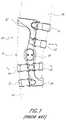
- FIG. 1is a right-side elevational view of a typical knee brace
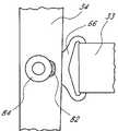
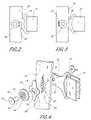
- FIG. 2is a right-side elevational view of a preferred embodiment of the present strap tension indicator, illustrating the indicator in a first position;
- FIG. 3is a right-side elevational view of the strap tension indicator of FIG. 2 , illustrating the indicator in a second position;
- FIG. 4is an exploded assembly view of the strap tension indicator of FIG. 2 , taken from a rear/right-side perspective;
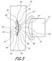
- FIG. 5is a right-side elevational view of the strap tension indicator of FIG. 2 , illustrating the rivet, cap and marker label removed to expose the resilient member;
- FIG. 6is a right-side elevational view of another preferred embodiment of the present strap tension indicator, illustrating the indicator in a first position
- FIG. 7is a right-side elevational view of the strap tension indicator of FIG. 6 , illustrating the indicator in a second position;
- FIG. 8is a right-side elevational view of the strap tension indicator of FIG. 6 , illustrating the indicator in a third position;
- FIG. 9is a right-side elevational view of another preferred embodiment of the present strap tension indicator, illustrating the indicator in a first position
- FIG. 10is a right-side elevational view of the strap tension indicator of FIG. 9 , illustrating the indicator in a second position;
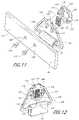
- FIG. 11is an exploded assembly view of another preferred embodiment of the present strap tension indicator, taken from a lower/front/left-side perspective;
- FIG. 12is a perspective view of components of the strap tension indicator of FIG. 11 , taken from a top/front/left-side perspective;
- FIG. 13is a right-side elevational view of the strap tension indicator of FIG. 11 , illustrating the indicator in a first position;
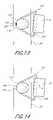
- FIG. 14is a right-side elevational view of the strap tension indicator of FIG. 11 , illustrating the indicator in a second position;
- FIG. 15is a left-side elevational view of components of the strap tension indicator of FIG. 11 , illustrating the indicator in the first position;
- FIG. 16is a left-side elevational view of the components of the strap tension indicator of FIG. 15 , illustrating the indicator in the second position.
- FIG. 1illustrates a typical knee brace 20 .
- the brace 20is readily modified to include the present strap tension indicator.
- the particular configuration of cuffs and straps shownmerely illustrates one example of a use for the present strap tension indicator.
- the present strap tension indicatoris useful in knee braces having alternate configurations.
- the strap tension indicatoris illustrated herein within the context of a knee brace, those of skill in the art will appreciate that the strap tension indicator could be used in a variety of other braces.
- the strap tension indicatorcould be incorporated into an elbow brace, an ankle brace, a shoulder brace, a back brace, etc.
- the brace 20includes an upper rigid cuff 22 and a lower rigid cuff 24 .
- Hinges 26 located on the medial and lateral sides of the wearer's kneepivotably secure the cuffs 22 , 24 to one another.
- the upper cuff 22extends around the anterior portion of the wearer's thigh 28 , and downward to the hinges 26 along the lateral and medial sides of the wearer's thigh 28 .
- the lower cuff 24extends around the posterior portion of the wearer's calf 30 , and upward to the hinges 26 along the lateral and medial sides of the wearer's calf 30 .
- a plurality of straps 32extend around the wearer's thigh 28 and lower leg 30 .
- Tension in each strap 32applies force to the wearer's leg.
- a force applied by one strap 32generates resultant forces in the remaining straps 32 and in the cuffs 22 , 24 .
- the tension in each strap 32is preferably optimized to provide the brace 20 with the desired function, fit, and comfort.
- the brace 20 illustrated in FIG. 1comprises only the anterior strap 32 just below the wearer's knee 35 , and the posterior straps 32 directly adjacent the wearer's knee 35 .
- Tension in the anterior strap 32creates a force F 1 acting in a posterior direction on the wearer's calf 30 .
- the forces acting on the wearer's legmust be in equilibrium, or the brace 20 would not remain on the wearer's leg.
- the posterior force F 1generates a resultant anterior force F 2 and a resultant anterior force F 3 .
- the force F 2acts through the strap 32 on the posterior portion of the wearer's calf
- the force F 3acts through the strap 32 on the posterior portion of the wearer's thigh.
- the magnitude of the posterior force F 1must be equal to the sum of the magnitudes of the anterior forces F 2 and F 3 .
- the present strap tension indicatorconnects the ends of brace straps to the rigid cuffs of a brace.
- the indicatorprovides visual confirmation of optimal strap tension.
- the present strap tension indicatorindicates the tension in a single strap, while in certain other embodiments the present strap tension indicator indicates a tension difference between two opposing straps.
- the present strap tension indicatorneed not be used to connect every strap to a rigid component in a given brace.
- a bracemay employ the present strap tension indicator to connect only some of its straps to its rigid components.
- FIG. 4illustrates in detail a preferred embodiment of the present strap tension indicator.
- the indicatormounts a strap 33 to a rigid frame member 34 of a brace (not shown).
- the frame member 34includes an aperture 36 .
- the frame aperture 36is substantially triangular, with a first corner 38 and a second corner 40 of the triangle being aligned along a longitudinal axis of the frame member 34 .
- a first side 42 of the aperture 36 extending between the first and second corners 38 , 40preferably includes an arcuate indentation 44 that seats a rivet 46 , as described below.
- Second and third sides 48 , 50 of the aperture 36include peaks 52 adjacent the first and second corners 38 , 40 .
- the aperture 36houses a resilient member 54 .
- the resilient member 54is a V-shaped leaf spring comprising multiple layers.
- a preferred material for the resilient member 54is steel.
- the resilient member 54could be any other type of resilient device, such as a one-piece leaf spring, a coil spring or a block of resilient material such as polyurethane. The resilient member 54 resists movement of the rivet 46 within the aperture 36 , as described below.
- first and second ends 56 , 58 of the resilient member 54reside in the first and second corners 38 , 40 , respectively, of the aperture 36 . Portions of the resilient member 54 adjacent the first and second ends 56 , 58 rest against the peaks 52 in the second and third aperture sides 48 , 50 .
- the apex 60 of the V-shaped resilient member 54resides adjacent and spaced from a third corner 62 of the aperture 36 .
- the crotch 64 of the V-shaped resilient member 54defines a larger angle than that defined by the aperture third corner 62 . Therefore, the resilient member 54 is spaced from the second and third aperture sides 48 , 50 over most of its surface area. When the strap 33 is under minimal tension, preferably no portion of the resilient member 54 contacts the aperture second and third sides 48 , 50 in the area between the peaks 52 .
- each strap 33includes a strap tab 66 at either end.
- a strap tabas is well known in the art, connects a brace strap to a rigid brace frame member.
- the straps 33need not be connected to the rigid brace frame members with strap tabs 66 .
- the straps 33could be connected directly to the rigid brace frame members.
- the illustrated strap tab 66comprises a loop portion 68 that receives the strap 33 , and an elongate portion 70 that extends away from the strap end.
- the elongate portion 70 of the strap tab 66includes a through hole 72 that is spaced from the strap 33 .
- the rivet 46passes through the aperture 36 and the strap tab through hole 72 , and engages a washer 74 to secure the strap tab 66 to the frame member 34 .
- the rivet 46 and washer 74could be replaced with alternate fastening members, such as a bolt and nut.
- the rivet 46When there is minimal tension in the strap 33 , as shown in FIG. 5 , the rivet 46 seats within the arcuate indentation 44 on the aperture first side 42 .
- the crotch 64 of the V-shaped resilient member 54abuts the rivet 46 opposite the arcuate indentation 42 , thereby retaining the rivet 46 within the arcuate indentation 42 .
- a marker label 76comprising a flat sheet, abuts the frame member 34 outer surface and overlies the aperture 36 .
- the marker label 76is preferably a paper or plastic sticker having an adhesive backing that sticks to the frame member 34 .
- the marker label 76is shaped substantially as a diamond having rounded corners and concave sides.
- the label 76thus includes four rounded lobes extending outward from a center of the label 76 , with each lobe being oriented ninety-degrees from adjacent lobes.
- the marker label 76preferably covers the edges of the aperture 36 to improve the overall appearance of the brace 20 and to prevent dirt and debris from entering the aperture 36 .
- a center portion of the marker label 76includes an oval-shaped hole 78 through which the rivet 46 passes.
- a first lobe 80 of the marker label 76resides adjacent the indentation 44 in the aperture first side 42 .
- the first lobe 80includes a first indicator color, such as green.
- a second lobe 82 of the marker label 76opposite the first lobe 80 , resides adjacent the aperture third corner 62 .
- the second lobe 82includes a second indicator color, such as red.
- the colored lobes of the marker label 76could be replaced by colored portions on the rigid frame member 34 itself, such as painted portions.
- a cap 84overlies the marker label 76 .
- the cap 84comprises a circular ring having a flat surface (not shown) that abuts the marker label 76 .
- the rivet 46passes through a central hole 86 in the cap 84 .
- the cap 84includes a recess 88 that receives a head 90 of the rivet 46 .
- the rivet 46thus seats within the cap 84 to provide the brace 20 with a more streamlined appearance.
- the cap 84slides freely over the marker label 76 as the rivet 46 moves within the aperture 36 under the influence of tension in the strap 33 .
- the rivet 46When there is minimal tension in the strap 33 , the rivet 46 abuts the indentation 44 in the aperture first side 42 , as shown in FIG. 5 . In this position, the cap 84 covers the first lobe 80 and leaves the second lobe 82 uncovered, as shown in FIG. 2 . The visible red color indicates that the tension in the strap 33 is too low.
- the strap tab 66forces the rivet 46 to bear against the crotch 64 of the resilient member 54 .
- the force of the rivet 46 upon the resilient member 54flexes the resilient member 54 , allowing the rivet 46 to move toward the aperture third corner 62 .
- the cap 84slides across the marker label 76 , covering the red colored second lobe 82 and exposing the green colored first lobe 80 , as shown in FIG. 3 .
- the strap 33is properly tensioned. If strap tension drops, the resilient member 54 pushes the rivet 46 back toward the indentation 44 .
- the cap 84slides across the marker label 76 , covering the green colored first lobe 80 and exposing the red colored second lobe 82 , as shown in FIG. 2 .
- FIGS. 6-8illustrate another preferred embodiment of the present strap tension indicator having three indicator positions.
- the cap 84includes a notch 92 that overlies a third lobe 94 of the marker label 76 .
- the first and second lobes 80 , 82are both colored the same. For example, both the first and second lobes 80 , 82 may be colored red.
- a central portion 96 ( FIG. 7 ) of the third lobe 94is colored a second color, such as green.
- the present strap tension indicatormay embody a variety of other configurations.
- the green colored first lobe 80may be eliminated and the red colored second lobe 82 retained.
- proper strap tensiondoes not provide a colored visual indicator, while inadequate strap tension does.
- the green colored first lobe 80may be retained and the red colored second lobe 82 eliminated.
- the indicatormay include multiple tension indication levels, such as a continuous tension scale.
- any colors or symbolsmay be used to indicate inadequate tension, proper tension, and excessive tension. Rather than using colors to indicate tension, the indicator may use numbers, letters, or other symbolic indicator marks.
- the compliance characteristics of the resilient member 54are preferably selected so that proper strap tension moves the cap 84 into a position upon the marker label 76 such that the cap 84 exposes and/or covers various areas of the marker label 76 to indicate proper strap tension.
- Different straps in a given bracemay have different optimal tensions.
- a given brace incorporating the present strap tension indicatormay include a plurality of resilient members having different compliance characteristics.
- the optimal tensionmay change over a course of therapy.
- the componentsare readily disassembled so that the resilient member 54 may be modified or replaced. For example, if a bolt and nut are used to retain the various components of the strap tension indicator, the bolt and nut are easily unscrewed and reattached to one another.
- the strap tab 66includes only one loop portion 68 to which one strap 33 is attached.
- FIGS. 9 and 10illustrate an alternative embodiment of the present strap tension indicator in which the strap tab 98 includes two oppositely extending loop portions.
- the first loop portion 100includes an attached first strap 102
- the second loop portion 104includes an attached second strap 106 .
- the straps 102 , 106wrap in opposite directions around the wearer and exert forces on opposite sides of the wearer. As shown in FIG. 10 , tension in the first strap 102 tends to pull the strap tab 98 in a first direction with a first force F 1 .
- Tension in the second strap 106tends to pull the strap tab 98 in a second direction, opposite the first direction, with a second force F 2 .
- the tension indicatorindicates the difference between the first force F 1 and the second force F 2 .
- the first force F 1 acting on the indicator of FIGS. 9 and 10may be greater than the second force F 2 acting on the indicator. In certain other applications, the second force F 2 may be greater than the first force F 1 . If the indicator comprises an aperture 36 and a resilient member 54 like those pictured in FIG. 4 , then the greater of the first force F 1 and the second force F 2 preferably pulls the cap 84 toward the resilient member 54 .
- FIGS. 11-16illustrate another preferred embodiment of the present strap tension indicator.
- the indicatormounts a strap 33 to a rigid frame member 34 of a brace (not shown).
- the frame memberincludes first and second spaced apertures 108 .
- Fastening members 110extend through the apertures 108 from a first side 112 (preferably facing toward the wearer) of the rigid frame member 34 .
- the fastening members 110may comprise, for example, rivets or bolts.
- the fastening members 110engage a strap tab cap 114 that abuts a second side (preferably facing away from the wearer) of the rigid frame member 34 .
- the strap tab cap 114is substantially oval shaped in side elevational view.
- first and second posts 116extend from a first surface 118 of the strap tab cap 114 that abuts the rigid frame member second surface.
- the first surface 118is substantially U-shaped in side elevational view, such that the first surface 118 extends around a first end 120 ( FIG. 12 ) of the oval-shaped strap tab cap 114 and along approximately half of each of the sides of the oval-shaped strap tab cap 114 .
- Ends of the U-shaped first surface 118terminate in the posts 116 , such that the first and second posts 116 are located along edges of the strap tab cap 114 that are separated by a short axis of the oval.
- the first and second posts 116are properly spaced to extend into the apertures 108 in the rigid frame member 34 .
- the posts 116include central countersunk holes 122 that receive the fastening members 110 .
- the fastening members 110secure the strap tab cap 114 to the rigid frame member 34 .
- the strap tab cap 114could be secured to the rigid frame member 34 using other methods, such as adhesives or welding. If such attachment methods are used, then the rigid frame member 34 need not necessarily include the apertures 108 , and the strap tab cap 114 need not necessarily include the first and second posts 116 .
- a second end 124 of the oval-shaped strap tab cap 114opposite the first end 120 and spaced from the posts 116 , includes third and fourth posts 126 .
- the third and fourth posts 126extend from the strap tab cap 114 in the same direction as the first and second posts 116 .
- the third and fourth posts 126are spaced from one another along a line that is parallel to a line joining the first and second posts 116 .
- a portion of the second end 124 of the oval-shaped strap tab cap 114 , between the third and fourth posts 126includes an indentation 128 ( FIG. 11 ).
- the strap tab cap 114secures a strap tab 130 to the rigid frame member 34 .
- the strap tab 130is shaped substantially as a trapezoidal ring.
- the shorter parallel side 132 of the trapezoidincludes a tab 134 that projects outwardly from the side 132 in substantially the same plane as the strap tab 130 .
- the side 132further includes a pair of spaced apart fingers 136 that project inwardly from the side 132 in substantially the same plane as the strap tab 130 .
- the strap tab 130is arranged relative to the strap tab cap 114 such that the shorter parallel side 132 extends across the strap tab cap 114 in a direction parallel to an imaginary line drawn between the first and second posts 116 . Outer edges of the fingers 136 abut inner edges of the legs of the U-shaped first surface 118 .
- the strap tab 130is slidable with respect to the strap tab cap 114 between a first position ( FIG. 15 ) and a second position ( FIG. 16 ). In the first position, the outer edge 138 of the shorter parallel side 132 abuts inside surfaces 140 of each of the third and fourth posts 126 , and the tab 134 resides between the third and fourth posts 126 . In the second position, the inner edge 142 of the shorter parallel side 132 abuts the first and second posts 116 and ends of the fingers 136 preferably abut an inside surface 144 of the base portion of the U-shaped first surface 118 .
- a resilient member 146biases the strap tab 130 toward the first position.
- the resilient member 146comprises a pair of coil springs.
- the resilient member 146could embody a variety of alternate constructions, such as a block of resilient material, such as polyurethane.
- a first end of each resilient member 146abuts the inside surface 144 of the base portion of the U-shaped first surface 118 .
- a second end of each resilient member 146abuts the inside edge 142 of the shorter parallel side 132 of the strap tab 130 .
- the tab 134when the strap tab 130 is in the first position ( FIG. 13 ), the tab 134 extends beyond the concave edge of the indentation 128 in the second side 124 of the oval-shaped strap tab cap 114 .
- the strap tab 130When the strap tab 130 is in the second position ( FIG. 14 ), no portion of the tab 134 extends beyond the edge of the indentation 128 .
- a portion 148 of the rigid frame member 34preferably bears a color that contrasts with the color of the tab 134 .
- a strap 33is secured to the longer parallel side 150 of the strap tab 130 .
- Tension in the strap 33pulls the strap tab 130 toward the second position with a force F, counteracting the force in the resilient member 146 that tends to push the strap tab 130 back toward the first position.
- the strap tab 130moves to the second position only when the strap 33 is under the desired amount of tension.
- the displaced tab 134exposes the colored portion 148 on the rigid frame member 34 , thereby indicating that the strap is under the desired amount of tension.
Landscapes
- Health & Medical Sciences (AREA)
- Engineering & Computer Science (AREA)
- Biomedical Technology (AREA)
- Heart & Thoracic Surgery (AREA)
- Vascular Medicine (AREA)
- Life Sciences & Earth Sciences (AREA)
- Animal Behavior & Ethology (AREA)
- General Health & Medical Sciences (AREA)
- Public Health (AREA)
- Veterinary Medicine (AREA)
- Nursing (AREA)
- Orthopedic Medicine & Surgery (AREA)
- Orthopedics, Nursing, And Contraception (AREA)
Abstract
Description
Claims (47)
Priority Applications (6)
| Application Number | Priority Date | Filing Date | Title |
|---|---|---|---|
| US10/753,088US7285103B2 (en) | 2004-01-07 | 2004-01-07 | Strap tension indicator for orthopedic brace |
| PCT/US2005/001207WO2005067825A1 (en) | 2004-01-07 | 2005-01-03 | Strap tension indicator for orthopedic brace |
| EP05705701AEP1703872A1 (en) | 2004-01-07 | 2005-01-03 | Strap tension indicator for orthopedic brace |
| JP2006549620AJP2007517632A (en) | 2004-01-07 | 2005-01-03 | Strap tension indicator for orthopedic orthosis |
| AU2005204925AAU2005204925A1 (en) | 2004-01-07 | 2005-01-03 | Strap tension indicator for orthopedic brace |
| CA002549987ACA2549987A1 (en) | 2004-01-07 | 2005-01-03 | Strap tension indicator for orthopedic brace |
Applications Claiming Priority (1)
| Application Number | Priority Date | Filing Date | Title |
|---|---|---|---|
| US10/753,088US7285103B2 (en) | 2004-01-07 | 2004-01-07 | Strap tension indicator for orthopedic brace |
Publications (2)
| Publication Number | Publication Date |
|---|---|
| US20050148917A1 US20050148917A1 (en) | 2005-07-07 |
| US7285103B2true US7285103B2 (en) | 2007-10-23 |
Family
ID=34711739
Family Applications (1)
| Application Number | Title | Priority Date | Filing Date |
|---|---|---|---|
| US10/753,088Active2026-02-05US7285103B2 (en) | 2004-01-07 | 2004-01-07 | Strap tension indicator for orthopedic brace |
Country Status (6)
| Country | Link |
|---|---|
| US (1) | US7285103B2 (en) |
| EP (1) | EP1703872A1 (en) |
| JP (1) | JP2007517632A (en) |
| AU (1) | AU2005204925A1 (en) |
| CA (1) | CA2549987A1 (en) |
| WO (1) | WO2005067825A1 (en) |
Cited By (33)
| Publication number | Priority date | Publication date | Assignee | Title |
|---|---|---|---|---|
| US20090168612A1 (en)* | 2004-12-01 | 2009-07-02 | Eta Sa Manufacture Horlogere Suisse | Element for indicating the fastening tension of a band, particularly for a bracelet for a portable device |
| US20100082060A1 (en)* | 2008-09-30 | 2010-04-01 | Tyco Healthcare Group Lp | Compression Device with Wear Area |
| USD637942S1 (en) | 2010-08-20 | 2011-05-17 | Ossur Hf | Strap retainer |
| US8016778B2 (en) | 2007-04-09 | 2011-09-13 | Tyco Healthcare Group Lp | Compression device with improved moisture evaporation |
| US8016779B2 (en) | 2007-04-09 | 2011-09-13 | Tyco Healthcare Group Lp | Compression device having cooling capability |
| US8021388B2 (en) | 2007-04-09 | 2011-09-20 | Tyco Healthcare Group Lp | Compression device with improved moisture evaporation |
| US8029450B2 (en) | 2007-04-09 | 2011-10-04 | Tyco Healthcare Group Lp | Breathable compression device |
| US8029451B2 (en) | 2005-12-12 | 2011-10-04 | Tyco Healthcare Group Lp | Compression sleeve having air conduits |
| US8034007B2 (en) | 2007-04-09 | 2011-10-11 | Tyco Healthcare Group Lp | Compression device with structural support features |
| US8070699B2 (en) | 2007-04-09 | 2011-12-06 | Tyco Healthcare Group Lp | Method of making compression sleeve with structural support features |
| US8109892B2 (en) | 2007-04-09 | 2012-02-07 | Tyco Healthcare Group Lp | Methods of making compression device with improved evaporation |
| US8128584B2 (en) | 2007-04-09 | 2012-03-06 | Tyco Healthcare Group Lp | Compression device with S-shaped bladder |
| US8162861B2 (en) | 2007-04-09 | 2012-04-24 | Tyco Healthcare Group Lp | Compression device with strategic weld construction |
| US8235923B2 (en) | 2008-09-30 | 2012-08-07 | Tyco Healthcare Group Lp | Compression device with removable portion |
| WO2012134689A1 (en)* | 2011-03-28 | 2012-10-04 | Ams Research Corporation | Implants, tools, and methods for treatments of pelvic conditions |
| US8506508B2 (en) | 2007-04-09 | 2013-08-13 | Covidien Lp | Compression device having weld seam moisture transfer |
| US8539647B2 (en) | 2005-07-26 | 2013-09-24 | Covidien Ag | Limited durability fastening for a garment |
| US8652079B2 (en) | 2010-04-02 | 2014-02-18 | Covidien Lp | Compression garment having an extension |
| US8740829B2 (en) | 2010-08-20 | 2014-06-03 | Ossur Hf | Configurable subshell components in orthopedic devices |
| US8808162B2 (en) | 2011-03-28 | 2014-08-19 | Ams Research Corporation | Implants, tools, and methods for treatment of pelvic conditions |
| USD721175S1 (en) | 2011-09-08 | 2015-01-13 | Ams Research Corporation | Backers for surgical indicators |
| USD721807S1 (en) | 2011-09-08 | 2015-01-27 | Ams Research Corporation | Surgical indicators |
| US8988235B2 (en) | 2011-04-22 | 2015-03-24 | Aspen Medical Partners, Llc | Force indicating attachment strap for an orthotic |
| US9089393B2 (en) | 2011-03-28 | 2015-07-28 | Ams Research Corporation | Implants, tools, and methods for treatment of pelvic conditions |
| USD736382S1 (en) | 2011-09-08 | 2015-08-11 | Ams Research Corporation | Surgical indicator with backers |
| US20150290016A1 (en)* | 2014-04-15 | 2015-10-15 | A Step Forward, Llc | Orthopedic device |
| US9205021B2 (en) | 2012-06-18 | 2015-12-08 | Covidien Lp | Compression system with vent cooling feature |
| US9510967B2 (en) | 2012-06-08 | 2016-12-06 | Ossur Hf | Orthopedic device and components thereof |
| US10588770B2 (en) | 2014-07-10 | 2020-03-17 | Ossur Hf | Versatile orthopedic device |
| US10751221B2 (en) | 2010-09-14 | 2020-08-25 | Kpr U.S., Llc | Compression sleeve with improved position retention |
| US11839564B1 (en) | 2019-08-08 | 2023-12-12 | Preferred Prescription, INC | Knee orthosis, adjustable |
| US11918500B1 (en) | 2020-03-31 | 2024-03-05 | Preferred Prescription, Inc. | Hinged knee brace with double upper strap arrangement |
| US12121463B1 (en) | 2020-02-13 | 2024-10-22 | Preferred Prescription, Inc. | Knee/elbow brace |
Families Citing this family (14)
| Publication number | Priority date | Publication date | Assignee | Title |
|---|---|---|---|---|
| WO2005097015A2 (en)* | 2004-03-31 | 2005-10-20 | Djo, Llc | Rotatable strap tab cap |
| JP4684081B2 (en)* | 2005-10-31 | 2011-05-18 | 保 佐喜眞 | Joint support orthosis |
| GB2461691B (en)* | 2008-07-07 | 2011-04-20 | David Henry Fryett Sir | Swimming goggles with tension device gauge |
| US9925082B2 (en)* | 2012-03-20 | 2018-03-27 | Ossur Hf | Orthopedic device |
| US9271860B2 (en) | 2012-03-20 | 2016-03-01 | Ossur Hf | Orthopedic device |
| WO2017176680A1 (en) | 2016-04-04 | 2017-10-12 | Ossur Iceland Ehf | Orthopedic device |
| CH712939B1 (en) | 2016-09-20 | 2020-04-30 | Sigvaris Ag | Compression garment |
| CH712938B1 (en) | 2016-09-20 | 2020-04-30 | Sigvaris Ag | Compression garment. |
| USD835289S1 (en) | 2016-11-08 | 2018-12-04 | Ossur Iceland Ehf | Orthopedic device |
| USD813089S1 (en) | 2016-11-08 | 2018-03-20 | Ossur Iceland Ehf | D-ring |
| US11051987B2 (en) | 2017-02-27 | 2021-07-06 | Sigvaris Ag | Method for tailoring a compression garment |
| PL3849479T3 (en)* | 2018-08-08 | 2025-03-17 | Sigvaris Ag | System for tailoring a compression garment |
| CN108904032A (en)* | 2018-08-27 | 2018-11-30 | 黄玮 | A kind of double button steel plate list loop fixed mechanisms and fixed system |
| US11086297B2 (en) | 2018-12-04 | 2021-08-10 | Sigvaris Ag | Methods and systems for fabricating, evaluating and improving therapeutic compression garments |
Citations (13)
| Publication number | Priority date | Publication date | Assignee | Title |
|---|---|---|---|---|
| US3613679A (en) | 1969-10-01 | 1971-10-19 | Patricia W Bijou | Elastic bandage with tension indicator |
| US4457251A (en) | 1978-03-15 | 1984-07-03 | N. V. Klippan S.A. | Belt load indicator |
| US4991571A (en) | 1988-09-08 | 1991-02-12 | Kausek James H | Modular knee brace for control of ligament instability |
| US5111806A (en) | 1991-08-01 | 1992-05-12 | Champion Ergonomics, Inc. | Support belt with color indicator |
| US5503620A (en) | 1994-07-01 | 1996-04-02 | Charm-Tex Inc. | Back support belt apparatus and method |
| US5779659A (en) | 1992-12-01 | 1998-07-14 | Convatec Limited | Elastic bandage with tension indicator |
| US6050967A (en) | 1997-05-08 | 2000-04-18 | Avcor Health Care Products, Inc. | Bandage compression indicator |
| US6152893A (en) | 1996-04-20 | 2000-11-28 | Smith & Nephew Plc | Compression device |
| US6325773B1 (en) | 1999-06-17 | 2001-12-04 | Charles F. Opel | Hinge appliance for minimizing knee injuries |
| US6338723B1 (en) | 1998-09-16 | 2002-01-15 | Circaid Medical Produts, Inc. | Compression device with compression measuring system |
| US20030045826A1 (en) | 2001-08-29 | 2003-03-06 | Meyer Nicholas Joseph | Forearm support band with direct pressure monitoring |
| US20030078528A1 (en) | 2001-10-01 | 2003-04-24 | Tariq Rahman | Brace compliance monitor |
| US7117569B2 (en)* | 2005-02-09 | 2006-10-10 | Medical Technology, Inc. | Adjustable ratchet buckle fastener |
- 2004
- 2004-01-07USUS10/753,088patent/US7285103B2/enactiveActive
- 2005
- 2005-01-03JPJP2006549620Apatent/JP2007517632A/ennot_activeWithdrawn
- 2005-01-03CACA002549987Apatent/CA2549987A1/ennot_activeAbandoned
- 2005-01-03AUAU2005204925Apatent/AU2005204925A1/ennot_activeAbandoned
- 2005-01-03EPEP05705701Apatent/EP1703872A1/ennot_activeWithdrawn
- 2005-01-03WOPCT/US2005/001207patent/WO2005067825A1/ennot_activeApplication Discontinuation
Patent Citations (13)
| Publication number | Priority date | Publication date | Assignee | Title |
|---|---|---|---|---|
| US3613679A (en) | 1969-10-01 | 1971-10-19 | Patricia W Bijou | Elastic bandage with tension indicator |
| US4457251A (en) | 1978-03-15 | 1984-07-03 | N. V. Klippan S.A. | Belt load indicator |
| US4991571A (en) | 1988-09-08 | 1991-02-12 | Kausek James H | Modular knee brace for control of ligament instability |
| US5111806A (en) | 1991-08-01 | 1992-05-12 | Champion Ergonomics, Inc. | Support belt with color indicator |
| US5779659A (en) | 1992-12-01 | 1998-07-14 | Convatec Limited | Elastic bandage with tension indicator |
| US5503620A (en) | 1994-07-01 | 1996-04-02 | Charm-Tex Inc. | Back support belt apparatus and method |
| US6152893A (en) | 1996-04-20 | 2000-11-28 | Smith & Nephew Plc | Compression device |
| US6050967A (en) | 1997-05-08 | 2000-04-18 | Avcor Health Care Products, Inc. | Bandage compression indicator |
| US6338723B1 (en) | 1998-09-16 | 2002-01-15 | Circaid Medical Produts, Inc. | Compression device with compression measuring system |
| US6325773B1 (en) | 1999-06-17 | 2001-12-04 | Charles F. Opel | Hinge appliance for minimizing knee injuries |
| US20030045826A1 (en) | 2001-08-29 | 2003-03-06 | Meyer Nicholas Joseph | Forearm support band with direct pressure monitoring |
| US20030078528A1 (en) | 2001-10-01 | 2003-04-24 | Tariq Rahman | Brace compliance monitor |
| US7117569B2 (en)* | 2005-02-09 | 2006-10-10 | Medical Technology, Inc. | Adjustable ratchet buckle fastener |
Cited By (58)
| Publication number | Priority date | Publication date | Assignee | Title |
|---|---|---|---|---|
| US20090168612A1 (en)* | 2004-12-01 | 2009-07-02 | Eta Sa Manufacture Horlogere Suisse | Element for indicating the fastening tension of a band, particularly for a bracelet for a portable device |
| US9364037B2 (en) | 2005-07-26 | 2016-06-14 | Covidien Ag | Limited durability fastening for a garment |
| US8539647B2 (en) | 2005-07-26 | 2013-09-24 | Covidien Ag | Limited durability fastening for a garment |
| US8029451B2 (en) | 2005-12-12 | 2011-10-04 | Tyco Healthcare Group Lp | Compression sleeve having air conduits |
| US8079970B2 (en) | 2005-12-12 | 2011-12-20 | Tyco Healthcare Group Lp | Compression sleeve having air conduits formed by a textured surface |
| US9387146B2 (en) | 2007-04-09 | 2016-07-12 | Covidien Lp | Compression device having weld seam moisture transfer |
| US8740828B2 (en) | 2007-04-09 | 2014-06-03 | Covidien Lp | Compression device with improved moisture evaporation |
| US8021388B2 (en) | 2007-04-09 | 2011-09-20 | Tyco Healthcare Group Lp | Compression device with improved moisture evaporation |
| US8034007B2 (en) | 2007-04-09 | 2011-10-11 | Tyco Healthcare Group Lp | Compression device with structural support features |
| US8070699B2 (en) | 2007-04-09 | 2011-12-06 | Tyco Healthcare Group Lp | Method of making compression sleeve with structural support features |
| US8016779B2 (en) | 2007-04-09 | 2011-09-13 | Tyco Healthcare Group Lp | Compression device having cooling capability |
| US8109892B2 (en) | 2007-04-09 | 2012-02-07 | Tyco Healthcare Group Lp | Methods of making compression device with improved evaporation |
| US8992449B2 (en) | 2007-04-09 | 2015-03-31 | Covidien Lp | Method of making compression sleeve with structural support features |
| US8128584B2 (en) | 2007-04-09 | 2012-03-06 | Tyco Healthcare Group Lp | Compression device with S-shaped bladder |
| US8162861B2 (en) | 2007-04-09 | 2012-04-24 | Tyco Healthcare Group Lp | Compression device with strategic weld construction |
| US9084713B2 (en) | 2007-04-09 | 2015-07-21 | Covidien Lp | Compression device having cooling capability |
| US9107793B2 (en) | 2007-04-09 | 2015-08-18 | Covidien Lp | Compression device with structural support features |
| US8506508B2 (en) | 2007-04-09 | 2013-08-13 | Covidien Lp | Compression device having weld seam moisture transfer |
| US8016778B2 (en) | 2007-04-09 | 2011-09-13 | Tyco Healthcare Group Lp | Compression device with improved moisture evaporation |
| US8597215B2 (en) | 2007-04-09 | 2013-12-03 | Covidien Lp | Compression device with structural support features |
| US8622942B2 (en) | 2007-04-09 | 2014-01-07 | Covidien Lp | Method of making compression sleeve with structural support features |
| US9114052B2 (en) | 2007-04-09 | 2015-08-25 | Covidien Lp | Compression device with strategic weld construction |
| US9808395B2 (en) | 2007-04-09 | 2017-11-07 | Covidien Lp | Compression device having cooling capability |
| US8721575B2 (en) | 2007-04-09 | 2014-05-13 | Covidien Lp | Compression device with s-shaped bladder |
| US8029450B2 (en) | 2007-04-09 | 2011-10-04 | Tyco Healthcare Group Lp | Breathable compression device |
| US10137052B2 (en) | 2008-04-07 | 2018-11-27 | Kpr U.S., Llc | Compression device with wear area |
| US20100082060A1 (en)* | 2008-09-30 | 2010-04-01 | Tyco Healthcare Group Lp | Compression Device with Wear Area |
| US8632840B2 (en) | 2008-09-30 | 2014-01-21 | Covidien Lp | Compression device with wear area |
| US8235923B2 (en) | 2008-09-30 | 2012-08-07 | Tyco Healthcare Group Lp | Compression device with removable portion |
| US8114117B2 (en)* | 2008-09-30 | 2012-02-14 | Tyco Healthcare Group Lp | Compression device with wear area |
| US8652079B2 (en) | 2010-04-02 | 2014-02-18 | Covidien Lp | Compression garment having an extension |
| US10772387B2 (en) | 2010-08-20 | 2020-09-15 | Ossur Hf | Configurable subshell components in orthopedic devices |
| US8740829B2 (en) | 2010-08-20 | 2014-06-03 | Ossur Hf | Configurable subshell components in orthopedic devices |
| US9345607B2 (en) | 2010-08-20 | 2016-05-24 | Ossur Hf | Configurable subshell components in orthopedic devices |
| USD637942S1 (en) | 2010-08-20 | 2011-05-17 | Ossur Hf | Strap retainer |
| US10751221B2 (en) | 2010-09-14 | 2020-08-25 | Kpr U.S., Llc | Compression sleeve with improved position retention |
| US10039629B2 (en) | 2011-03-28 | 2018-08-07 | Boston Scientific Scimed, Inc. | Implants, tools, and methods for treatment of pelvic conditions |
| US8808162B2 (en) | 2011-03-28 | 2014-08-19 | Ams Research Corporation | Implants, tools, and methods for treatment of pelvic conditions |
| US10034735B2 (en) | 2011-03-28 | 2018-07-31 | Boston Scientific Scimed, Inc. | Implants, tools, and methods for treatments of pelvic conditions |
| US9089393B2 (en) | 2011-03-28 | 2015-07-28 | Ams Research Corporation | Implants, tools, and methods for treatment of pelvic conditions |
| US9179992B2 (en) | 2011-03-28 | 2015-11-10 | Ams Research Corporation | Implants, tools, and methods for treatment of pelvic conditions |
| WO2012134689A1 (en)* | 2011-03-28 | 2012-10-04 | Ams Research Corporation | Implants, tools, and methods for treatments of pelvic conditions |
| US9750590B2 (en) | 2011-03-28 | 2017-09-05 | Andrew P. VanDeWeghe | Implants, tools, and methods for treatment of pelvic conditions |
| US8988235B2 (en) | 2011-04-22 | 2015-03-24 | Aspen Medical Partners, Llc | Force indicating attachment strap for an orthotic |
| USD736382S1 (en) | 2011-09-08 | 2015-08-11 | Ams Research Corporation | Surgical indicator with backers |
| USD746462S1 (en) | 2011-09-08 | 2015-12-29 | Ams Research Corporation | Surgical indicators |
| USD721175S1 (en) | 2011-09-08 | 2015-01-13 | Ams Research Corporation | Backers for surgical indicators |
| USD721807S1 (en) | 2011-09-08 | 2015-01-27 | Ams Research Corporation | Surgical indicators |
| US9510967B2 (en) | 2012-06-08 | 2016-12-06 | Ossur Hf | Orthopedic device and components thereof |
| US9205021B2 (en) | 2012-06-18 | 2015-12-08 | Covidien Lp | Compression system with vent cooling feature |
| WO2015160700A1 (en)* | 2014-04-15 | 2015-10-22 | A Step Forward, Llc | Orthopedic device |
| US20150290016A1 (en)* | 2014-04-15 | 2015-10-15 | A Step Forward, Llc | Orthopedic device |
| US10588770B2 (en) | 2014-07-10 | 2020-03-17 | Ossur Hf | Versatile orthopedic device |
| US11564823B2 (en) | 2014-07-10 | 2023-01-31 | Ossur Hf | Versatile orthopedic device |
| US12076262B2 (en) | 2014-07-10 | 2024-09-03 | Ossur Mf | Versatile orthopedic device |
| US11839564B1 (en) | 2019-08-08 | 2023-12-12 | Preferred Prescription, INC | Knee orthosis, adjustable |
| US12121463B1 (en) | 2020-02-13 | 2024-10-22 | Preferred Prescription, Inc. | Knee/elbow brace |
| US11918500B1 (en) | 2020-03-31 | 2024-03-05 | Preferred Prescription, Inc. | Hinged knee brace with double upper strap arrangement |
Also Published As
| Publication number | Publication date |
|---|---|
| JP2007517632A (en) | 2007-07-05 |
| EP1703872A1 (en) | 2006-09-27 |
| US20050148917A1 (en) | 2005-07-07 |
| CA2549987A1 (en) | 2005-07-28 |
| WO2005067825A1 (en) | 2005-07-28 |
| AU2005204925A1 (en) | 2005-07-28 |
Similar Documents
| Publication | Publication Date | Title |
|---|---|---|
| US7285103B2 (en) | Strap tension indicator for orthopedic brace | |
| US10806620B2 (en) | Orthopedic device | |
| US7264605B2 (en) | Knee support device for applying radial pressure | |
| EP1437109B1 (en) | Lumbar supporter | |
| US5111806A (en) | Support belt with color indicator | |
| CA2121342C (en) | Adjustable knee support | |
| US20050038367A1 (en) | Adjustable knee stabilizer | |
| US4850056A (en) | Athletic pants | |
| US7556608B2 (en) | Device for supporting lumbar vertebras and/or sacrospinal muscles | |
| US5277699A (en) | Foot drop orthotic and gait training device | |
| US20110130694A1 (en) | Adjustable wrist brace | |
| EP0998246B1 (en) | Ankle support brace | |
| US20040225245A1 (en) | Knee brace with directional elastic | |
| US4102337A (en) | Below knee orthosis | |
| EP2869795B1 (en) | Girdle | |
| JPH0138481B2 (en) | ||
| KR20080091226A (en) | Harness for stretching the penis | |
| EA032887B1 (en) | Knee supporter | |
| US20030171706A1 (en) | Adjustable size ankle brace | |
| EP3856094B1 (en) | Ankle brace | |
| US5139015A (en) | Knee support wrap for lifting weights | |
| US5070868A (en) | Adjustable splint | |
| GB2241170A (en) | A support for a joint | |
| NL1004821C2 (en) | Support bandage for correcting position of pelvis | |
| JP6559168B2 (en) | corset |
Legal Events
| Date | Code | Title | Description |
|---|---|---|---|
| AS | Assignment | Owner name:DJ ORTHOPEDICS, LLC, CALIFORNIA Free format text:ASSIGNMENT OF ASSIGNORS INTEREST;ASSIGNOR:NATHANSON, JEREMY J.;REEL/FRAME:015456/0694 Effective date:20040428 | |
| AS | Assignment | Owner name:WACHOVIA BANK, NATIONAL ASSOCIATION, NORTH CAROLIN Free format text:SECURITY INTEREST;ASSIGNOR:DJ ORTHOPEDICS LLC;REEL/FRAME:016313/0783 Effective date:20050505 | |
| AS | Assignment | Owner name:WACHOVIA BANK, N.A., NORTH CAROLINA Free format text:SECURITY AGREEMENT;ASSIGNOR:DJ ORTHOPEDICS, LLC;REEL/FRAME:017619/0316 Effective date:20060406 | |
| AS | Assignment | Owner name:DJO, LLC, CALIFORNIA Free format text:CHANGE OF NAME;ASSIGNOR:DJ ORTHOPEDICS, LLC;REEL/FRAME:018109/0123 Effective date:20060525 | |
| STCF | Information on status: patent grant | Free format text:PATENTED CASE | |
| AS | Assignment | Owner name:DJO, LLC, CALIFORNIA Free format text:RELEASE BY SECURED PARTY;ASSIGNOR:WACHOVIA BANK, NATIONAL ASSOCIATION, AS ADMINISTRATIVE AGENT;REEL/FRAME:020196/0931 Effective date:20071120 Owner name:DJO, LLC,CALIFORNIA Free format text:RELEASE BY SECURED PARTY;ASSIGNOR:WACHOVIA BANK, NATIONAL ASSOCIATION, AS ADMINISTRATIVE AGENT;REEL/FRAME:020196/0931 Effective date:20071120 | |
| AS | Assignment | Owner name:CREDIT SUISSE, AS COLLATERAL AGENT, NEW YORK Free format text:SECURITY AGREEMENT;ASSIGNOR:DJO, LLC;REEL/FRAME:020234/0393 Effective date:20071120 Owner name:CREDIT SUISSE, AS COLLATERAL AGENT,NEW YORK Free format text:SECURITY AGREEMENT;ASSIGNOR:DJO, LLC;REEL/FRAME:020234/0393 Effective date:20071120 | |
| FPAY | Fee payment | Year of fee payment:4 | |
| AS | Assignment | Owner name:THE BANK OF NEW YORK MELLON, AS SECOND LIEN AGENT, Free format text:SECURITY AGREEMENT;ASSIGNORS:DJO, LLC;EMPI, INC.;ENCORE MEDICAL ASSET CORPORATION;AND OTHERS;REEL/FRAME:028078/0320 Effective date:20120320 | |
| FPAY | Fee payment | Year of fee payment:8 | |
| AS | Assignment | Owner name:WELLS FARGO BANK, NATIONAL ASSOCIATION, AS THE COL Free format text:SECURITY INTEREST;ASSIGNORS:DJO, LLC;EMPI, INC.;ENCORE MEDICAL ASSET CORPORATION;AND OTHERS;REEL/FRAME:035614/0001 Effective date:20150507 | |
| AS | Assignment | Owner name:DJO, LLC, CALIFORNIA Free format text:RELEASE BY SECURED PARTY;ASSIGNOR:THE BANK OF NEW YORK MELLON, AS SECOND LIEN AGENT;REEL/FRAME:035706/0457 Effective date:20150507 Owner name:ENCORE MEDICAL ASSET CORPORATION, CALIFORNIA Free format text:RELEASE BY SECURED PARTY;ASSIGNOR:CREDIT SUISSE AG, AS COLLATERAL AGENT;REEL/FRAME:035706/0497 Effective date:20150507 Owner name:EMPI, INC., MINNESOTA Free format text:RELEASE BY SECURED PARTY;ASSIGNOR:THE BANK OF NEW YORK MELLON, AS SECOND LIEN AGENT;REEL/FRAME:035706/0457 Effective date:20150507 Owner name:ENCORE MEDICAL ASSET CORPORATION, CALIFORNIA Free format text:RELEASE BY SECURED PARTY;ASSIGNOR:THE BANK OF NEW YORK MELLON, AS SECOND LIEN AGENT;REEL/FRAME:035706/0457 Effective date:20150507 Owner name:RIKCO INTERNATIONAL, LLC, WISCONSIN Free format text:RELEASE BY SECURED PARTY;ASSIGNOR:THE BANK OF NEW YORK MELLON, AS SECOND LIEN AGENT;REEL/FRAME:035706/0457 Effective date:20150507 Owner name:RIKCO INTERNATIONAL, LLC, WISCONSIN Free format text:RELEASE BY SECURED PARTY;ASSIGNOR:CREDIT SUISSE AG, AS COLLATERAL AGENT;REEL/FRAME:035706/0497 Effective date:20150507 Owner name:DJO, LLC, CALIFORNIA Free format text:RELEASE BY SECURED PARTY;ASSIGNOR:CREDIT SUISSE AG, AS COLLATERAL AGENT;REEL/FRAME:035706/0497 Effective date:20150507 Owner name:MACQUARIE US TRADING LLC, AS COLLATERAL AGENT, ILL Free format text:SECURITY AGREEMENT;ASSIGNORS:DJO, LLC;EMPI, INC.;ENCORE MEDICAL ASSET CORPORATION;AND OTHERS;REEL/FRAME:035707/0398 Effective date:20150507 Owner name:THE BANK OF NEW YORK MELLON, AS SECOND LIEN AGENT, Free format text:SECURITY AGREEMENT;ASSIGNORS:DJO, LLC;EMPI, INC.;ENCORE MEDICAL ASSET CORPORATION;AND OTHERS;REEL/FRAME:035707/0454 Effective date:20150507 Owner name:THE BANK OF NEW YORK MELLON, AS THIRD LIEN AGENT, Free format text:SECURITY AGREEMENT;ASSIGNORS:DJO, LLC;EMPI, INC.;ENCORE MEDICAL ASSET CORPORATION;AND OTHERS;REEL/FRAME:035707/0498 Effective date:20150507 | |
| AS | Assignment | Owner name:ENCORE MEDICAL ASSET CORPORATION, CALIFORNIA Free format text:RELEASE BY SECURED PARTY;ASSIGNOR:MACQUARIE US TRADING LLC AS COLLATERAL AGENT;REEL/FRAME:048655/0067 Effective date:20190222 Owner name:ENCORE MEDICAL, L.P., CALIFORNIA Free format text:RELEASE BY SECURED PARTY;ASSIGNOR:MACQUARIE US TRADING LLC AS COLLATERAL AGENT;REEL/FRAME:048655/0067 Effective date:20190222 Owner name:RIKCO INTERNATIONAL, LLC, CALIFORNIA Free format text:RELEASE BY SECURED PARTY;ASSIGNOR:MACQUARIE US TRADING LLC AS COLLATERAL AGENT;REEL/FRAME:048655/0067 Effective date:20190222 Owner name:EMPI, INC., CALIFORNIA Free format text:RELEASE BY SECURED PARTY;ASSIGNOR:MACQUARIE US TRADING LLC AS COLLATERAL AGENT;REEL/FRAME:048655/0067 Effective date:20190222 Owner name:DJO, LLC, CALIFORNIA Free format text:RELEASE BY SECURED PARTY;ASSIGNOR:MACQUARIE US TRADING LLC AS COLLATERAL AGENT;REEL/FRAME:048655/0067 Effective date:20190222 Owner name:ENCORE MEDICAL, L.P., CALIFORNIA Free format text:RELEASE BY SECURED PARTY;ASSIGNOR:THE BANK OF NEW YORK MELLON AS THIRD LIEN AGENT;REEL/FRAME:048608/0932 Effective date:20190222 Owner name:ENCORE MEDICAL ASSET CORPORATION, CALIFORNIA Free format text:RELEASE BY SECURED PARTY;ASSIGNOR:THE BANK OF NEW YORK MELLON AS THIRD LIEN AGENT;REEL/FRAME:048608/0932 Effective date:20190222 Owner name:DJO, LLC, CALIFORNIA Free format text:RELEASE BY SECURED PARTY;ASSIGNOR:THE BANK OF NEW YORK MELLON AS THIRD LIEN AGENT;REEL/FRAME:048608/0932 Effective date:20190222 Owner name:EMPI, INC., CALIFORNIA Free format text:RELEASE BY SECURED PARTY;ASSIGNOR:THE BANK OF NEW YORK MELLON AS THIRD LIEN AGENT;REEL/FRAME:048608/0932 Effective date:20190222 Owner name:RIKCO INTERNATIONAL, LLC, CALIFORNIA Free format text:RELEASE BY SECURED PARTY;ASSIGNOR:THE BANK OF NEW YORK MELLON AS THIRD LIEN AGENT;REEL/FRAME:048608/0932 Effective date:20190222 Owner name:ENCORE MEDICAL ASSET CORPORATION, CALIFORNIA Free format text:RELEASE BY SECURED PARTY;ASSIGNOR:THE BANK OF NEW YORK MELLON AS SECOND LIEN AGENT;REEL/FRAME:050129/0262 Effective date:20190222 Owner name:ENCORE MEDICAL, L.P., CALIFORNIA Free format text:RELEASE BY SECURED PARTY;ASSIGNOR:THE BANK OF NEW YORK MELLON AS SECOND LIEN AGENT;REEL/FRAME:050129/0262 Effective date:20190222 Owner name:DJO, LLC, CALIFORNIA Free format text:RELEASE BY SECURED PARTY;ASSIGNOR:THE BANK OF NEW YORK MELLON AS SECOND LIEN AGENT;REEL/FRAME:050129/0262 Effective date:20190222 Owner name:EMPI, INC., CALIFORNIA Free format text:RELEASE BY SECURED PARTY;ASSIGNOR:THE BANK OF NEW YORK MELLON AS SECOND LIEN AGENT;REEL/FRAME:050129/0262 Effective date:20190222 Owner name:RIKCO INTERNATIONAL, LLC, CALIFORNIA Free format text:RELEASE BY SECURED PARTY;ASSIGNOR:THE BANK OF NEW YORK MELLON AS SECOND LIEN AGENT;REEL/FRAME:050129/0262 Effective date:20190222 | |
| AS | Assignment | Owner name:DJO, LLC, CALIFORNIA Free format text:RELEASE BY SECURED PARTY;ASSIGNOR:WELLS FARGO BANK, NATIONAL ASSOCIATION AS COLLATERAL AGENT;REEL/FRAME:048672/0661 Effective date:20190222 Owner name:EMPI, INC., CALIFORNIA Free format text:RELEASE BY SECURED PARTY;ASSIGNOR:WELLS FARGO BANK, NATIONAL ASSOCIATION AS COLLATERAL AGENT;REEL/FRAME:048672/0661 Effective date:20190222 Owner name:ENCORE MEDICAL ASSET CORPORATION, CALIFORNIA Free format text:RELEASE BY SECURED PARTY;ASSIGNOR:WELLS FARGO BANK, NATIONAL ASSOCIATION AS COLLATERAL AGENT;REEL/FRAME:048672/0661 Effective date:20190222 Owner name:RIKCO INTERNATIONAL, LLC, CALIFORNIA Free format text:RELEASE BY SECURED PARTY;ASSIGNOR:WELLS FARGO BANK, NATIONAL ASSOCIATION AS COLLATERAL AGENT;REEL/FRAME:048672/0661 Effective date:20190222 Owner name:ENCORE MEDICAL, L.P., CALIFORNIA Free format text:RELEASE BY SECURED PARTY;ASSIGNOR:WELLS FARGO BANK, NATIONAL ASSOCIATION AS COLLATERAL AGENT;REEL/FRAME:048672/0661 Effective date:20190222 | |
| MAFP | Maintenance fee payment | Free format text:PAYMENT OF MAINTENANCE FEE, 12TH YEAR, LARGE ENTITY (ORIGINAL EVENT CODE: M1553); ENTITY STATUS OF PATENT OWNER: LARGE ENTITY Year of fee payment:12 | |
| AS | Assignment | Owner name:JPMORGAN CHASE BANK, N.A., AS ADMINISTRATIVE AGENT, ILLINOIS Free format text:SECURITY INTEREST;ASSIGNOR:DJO, LLC;REEL/FRAME:066186/0659 Effective date:20240103 |