US7283714B1 - Large mode area fiber for low-loss transmission and amplification of single mode lasers - Google Patents
Large mode area fiber for low-loss transmission and amplification of single mode lasersDownload PDFInfo
- Publication number
- US7283714B1 US7283714B1US11/611,239US61123906AUS7283714B1US 7283714 B1US7283714 B1US 7283714B1US 61123906 AUS61123906 AUS 61123906AUS 7283714 B1US7283714 B1US 7283714B1
- Authority
- US
- United States
- Prior art keywords
- fiber
- cladding
- core
- effective
- refractive index
- Prior art date
- Legal status (The legal status is an assumption and is not a legal conclusion. Google has not performed a legal analysis and makes no representation as to the accuracy of the status listed.)
- Active
Links
- 239000000835fiberSubstances0.000titleclaimsabstractdescription122
- 230000005540biological transmissionEffects0.000titleclaimsdescription21
- 230000003321amplificationEffects0.000titledescription7
- 238000003199nucleic acid amplification methodMethods0.000titledescription7
- 238000005253claddingMethods0.000claimsabstractdescription97
- 239000013307optical fiberSubstances0.000claimsabstractdescription50
- VYPSYNLAJGMNEJ-UHFFFAOYSA-NSilicium dioxideChemical compoundO=[Si]=OVYPSYNLAJGMNEJ-UHFFFAOYSA-N0.000claimsdescription12
- 229910052761rare earth metalInorganic materials0.000claimsdescription8
- 239000007787solidSubstances0.000claimsdescription5
- 238000000862absorption spectrumMethods0.000claimsdescription4
- 238000000295emission spectrumMethods0.000claims1
- 230000008859changeEffects0.000abstractdescription7
- 239000010410layerSubstances0.000description19
- 239000004038photonic crystalSubstances0.000description7
- 239000000463materialSubstances0.000description5
- 229910052691ErbiumInorganic materials0.000description4
- 229910052769YtterbiumInorganic materials0.000description4
- 239000002019doping agentSubstances0.000description4
- 230000006872improvementEffects0.000description4
- 230000008901benefitEffects0.000description3
- 230000008878couplingEffects0.000description3
- 238000010168coupling processMethods0.000description3
- 238000005859coupling reactionMethods0.000description3
- 238000010586diagramMethods0.000description3
- UYAHIZSMUZPPFV-UHFFFAOYSA-NerbiumChemical compound[Er]UYAHIZSMUZPPFV-UHFFFAOYSA-N0.000description3
- 230000001681protective effectEffects0.000description3
- -1rare earth ionsChemical class0.000description3
- NAWDYIZEMPQZHO-UHFFFAOYSA-NytterbiumChemical compound[Yb]NAWDYIZEMPQZHO-UHFFFAOYSA-N0.000description3
- 238000005452bendingMethods0.000description2
- 238000010276constructionMethods0.000description2
- 239000011521glassSubstances0.000description2
- 238000012986modificationMethods0.000description2
- 230000004048modificationEffects0.000description2
- 230000009022nonlinear effectEffects0.000description2
- 229910052689HolmiumInorganic materials0.000description1
- 229910052779NeodymiumInorganic materials0.000description1
- 229910052775ThuliumInorganic materials0.000description1
- 239000006117anti-reflective coatingSubstances0.000description1
- 238000013459approachMethods0.000description1
- 238000005219brazingMethods0.000description1
- 239000002131composite materialSubstances0.000description1
- 239000013078crystalSubstances0.000description1
- 238000005520cutting processMethods0.000description1
- 230000007423decreaseEffects0.000description1
- 230000003247decreasing effectEffects0.000description1
- 238000009826distributionMethods0.000description1
- 238000005553drillingMethods0.000description1
- 239000002355dual-layerSubstances0.000description1
- 230000000694effectsEffects0.000description1
- 230000007613environmental effectEffects0.000description1
- 238000001125extrusionMethods0.000description1
- 229910052747lanthanoidInorganic materials0.000description1
- 150000002602lanthanoidsChemical class0.000description1
- 238000003698laser cuttingMethods0.000description1
- 238000003754machiningMethods0.000description1
- 238000004519manufacturing processMethods0.000description1
- 238000000034methodMethods0.000description1
- 239000000203mixtureSubstances0.000description1
- 230000003287optical effectEffects0.000description1
- 229920000642polymerPolymers0.000description1
- 239000002861polymer materialSubstances0.000description1
- 230000001902propagating effectEffects0.000description1
- 230000035945sensitivityEffects0.000description1
- 239000000377silicon dioxideSubstances0.000description1
- 239000011343solid materialSubstances0.000description1
- 238000003466weldingMethods0.000description1
Images


Classifications
- G—PHYSICS
- G02—OPTICS
- G02B—OPTICAL ELEMENTS, SYSTEMS OR APPARATUS
- G02B6/00—Light guides; Structural details of arrangements comprising light guides and other optical elements, e.g. couplings
- G02B6/02—Optical fibres with cladding with or without a coating
- G02B6/02004—Optical fibres with cladding with or without a coating characterised by the core effective area or mode field radius
- G02B6/02009—Large effective area or mode field radius, e.g. to reduce nonlinear effects in single mode fibres
- G—PHYSICS
- G02—OPTICS
- G02B—OPTICAL ELEMENTS, SYSTEMS OR APPARATUS
- G02B6/00—Light guides; Structural details of arrangements comprising light guides and other optical elements, e.g. couplings
- G02B6/02—Optical fibres with cladding with or without a coating
- G02B6/02295—Microstructured optical fibre
- G02B6/02314—Plurality of longitudinal structures extending along optical fibre axis, e.g. holes
- G02B6/02342—Plurality of longitudinal structures extending along optical fibre axis, e.g. holes characterised by cladding features, i.e. light confining region
- G02B6/02366—Single ring of structures, e.g. "air clad"
- G—PHYSICS
- G02—OPTICS
- G02B—OPTICAL ELEMENTS, SYSTEMS OR APPARATUS
- G02B6/00—Light guides; Structural details of arrangements comprising light guides and other optical elements, e.g. couplings
- G02B6/02—Optical fibres with cladding with or without a coating
- G02B6/036—Optical fibres with cladding with or without a coating core or cladding comprising multiple layers
- G02B6/03616—Optical fibres characterised both by the number of different refractive index layers around the central core segment, i.e. around the innermost high index core layer, and their relative refractive index difference
- G02B6/03638—Optical fibres characterised both by the number of different refractive index layers around the central core segment, i.e. around the innermost high index core layer, and their relative refractive index difference having 3 layers only
- G02B6/0365—Optical fibres characterised both by the number of different refractive index layers around the central core segment, i.e. around the innermost high index core layer, and their relative refractive index difference having 3 layers only arranged - - +
- G—PHYSICS
- G02—OPTICS
- G02B—OPTICAL ELEMENTS, SYSTEMS OR APPARATUS
- G02B6/00—Light guides; Structural details of arrangements comprising light guides and other optical elements, e.g. couplings
- G02B6/02—Optical fibres with cladding with or without a coating
- G02B6/036—Optical fibres with cladding with or without a coating core or cladding comprising multiple layers
- G02B6/03616—Optical fibres characterised both by the number of different refractive index layers around the central core segment, i.e. around the innermost high index core layer, and their relative refractive index difference
- G02B6/03661—Optical fibres characterised both by the number of different refractive index layers around the central core segment, i.e. around the innermost high index core layer, and their relative refractive index difference having 4 layers only
- G02B6/03666—Optical fibres characterised both by the number of different refractive index layers around the central core segment, i.e. around the innermost high index core layer, and their relative refractive index difference having 4 layers only arranged - + - +
- G—PHYSICS
- G02—OPTICS
- G02B—OPTICAL ELEMENTS, SYSTEMS OR APPARATUS
- G02B6/00—Light guides; Structural details of arrangements comprising light guides and other optical elements, e.g. couplings
- G02B6/02—Optical fibres with cladding with or without a coating
- G02B6/02295—Microstructured optical fibre
- G02B6/02314—Plurality of longitudinal structures extending along optical fibre axis, e.g. holes
- G02B6/02342—Plurality of longitudinal structures extending along optical fibre axis, e.g. holes characterised by cladding features, i.e. light confining region
- G02B6/02361—Longitudinal structures forming multiple layers around the core, e.g. arranged in multiple rings with each ring having longitudinal elements at substantially the same radial distance from the core, having rotational symmetry about the fibre axis
- G—PHYSICS
- G02—OPTICS
- G02B—OPTICAL ELEMENTS, SYSTEMS OR APPARATUS
- G02B6/00—Light guides; Structural details of arrangements comprising light guides and other optical elements, e.g. couplings
- G02B6/02—Optical fibres with cladding with or without a coating
- G02B6/036—Optical fibres with cladding with or without a coating core or cladding comprising multiple layers
- G02B6/03616—Optical fibres characterised both by the number of different refractive index layers around the central core segment, i.e. around the innermost high index core layer, and their relative refractive index difference
- G02B6/03688—Optical fibres characterised both by the number of different refractive index layers around the central core segment, i.e. around the innermost high index core layer, and their relative refractive index difference having 5 or more layers
- H—ELECTRICITY
- H01—ELECTRIC ELEMENTS
- H01S—DEVICES USING THE PROCESS OF LIGHT AMPLIFICATION BY STIMULATED EMISSION OF RADIATION [LASER] TO AMPLIFY OR GENERATE LIGHT; DEVICES USING STIMULATED EMISSION OF ELECTROMAGNETIC RADIATION IN WAVE RANGES OTHER THAN OPTICAL
- H01S3/00—Lasers, i.e. devices using stimulated emission of electromagnetic radiation in the infrared, visible or ultraviolet wave range
- H01S3/05—Construction or shape of optical resonators; Accommodation of active medium therein; Shape of active medium
- H01S3/06—Construction or shape of active medium
- H01S3/063—Waveguide lasers, i.e. whereby the dimensions of the waveguide are of the order of the light wavelength
- H01S3/067—Fibre lasers
- H01S3/06708—Constructional details of the fibre, e.g. compositions, cross-section, shape or tapering
- H01S3/06729—Peculiar transverse fibre profile
- H01S3/06741—Photonic crystal fibre, i.e. the fibre having a photonic bandgap
- H—ELECTRICITY
- H01—ELECTRIC ELEMENTS
- H01S—DEVICES USING THE PROCESS OF LIGHT AMPLIFICATION BY STIMULATED EMISSION OF RADIATION [LASER] TO AMPLIFY OR GENERATE LIGHT; DEVICES USING STIMULATED EMISSION OF ELECTROMAGNETIC RADIATION IN WAVE RANGES OTHER THAN OPTICAL
- H01S3/00—Lasers, i.e. devices using stimulated emission of electromagnetic radiation in the infrared, visible or ultraviolet wave range
- H01S3/05—Construction or shape of optical resonators; Accommodation of active medium therein; Shape of active medium
- H01S3/06—Construction or shape of active medium
- H01S3/063—Waveguide lasers, i.e. whereby the dimensions of the waveguide are of the order of the light wavelength
- H01S3/067—Fibre lasers
- H01S3/0675—Resonators including a grating structure, e.g. distributed Bragg reflectors [DBR] or distributed feedback [DFB] fibre lasers
- H—ELECTRICITY
- H01—ELECTRIC ELEMENTS
- H01S—DEVICES USING THE PROCESS OF LIGHT AMPLIFICATION BY STIMULATED EMISSION OF RADIATION [LASER] TO AMPLIFY OR GENERATE LIGHT; DEVICES USING STIMULATED EMISSION OF ELECTROMAGNETIC RADIATION IN WAVE RANGES OTHER THAN OPTICAL
- H01S3/00—Lasers, i.e. devices using stimulated emission of electromagnetic radiation in the infrared, visible or ultraviolet wave range
- H01S3/14—Lasers, i.e. devices using stimulated emission of electromagnetic radiation in the infrared, visible or ultraviolet wave range characterised by the material used as the active medium
- H01S3/16—Solid materials
- H01S3/1601—Solid materials characterised by an active (lasing) ion
- H01S3/1603—Solid materials characterised by an active (lasing) ion rare earth
- H01S3/1618—Solid materials characterised by an active (lasing) ion rare earth ytterbium
Definitions
- the present inventionrelates generally to optical fiber design and more particularly an optical fiber having a very large mode field core.
- High-power single-mode fiber lasers having output power in the range of 1-50 kWare now coming into widespread use in the industrial fields of welding, high-speed cutting, brazing, and drilling.
- Fiber lasershave high wall plug power efficiency, and very good beam characteristics.
- the beam from fiber laserscan be focused to small spot sizes with long focal length lenses with consistent beam properties independent of power level or pulse duration.
- Ytterbium single-mode fiber lasers with an M 2 of 1.1have continually increased in power to the multi-kW level, and can be focused to 10-15 ⁇ m spot diameters with perfect Gaussian distribution. Further increasing power will open up additional markets in the future.
- optical fibersexperience some signal loss due to attenuation and non-linearities within the fiber itself. Minimizing the effect of these imperfections is critical to maximizing the output power of the laser. To attain higher output power, it is desirable to use optical fibers with a large effective mode area while maintaining single mode guidance. Due to the reduced optical intensities, such fibers effectively have lower non-linearities and a higher damage threshold, which makes them suitable for such applications as the amplification of intense pulses or for single frequency signals, for example.
- PCFphotonic crystal fiber
- PCFphotonic crystal fiber
- holey fiber or microstructure fiberis an optical fiber, which derives its waveguide properties not from a spatially varying material composition, but from an arrangement of very tiny air holes, which extend longitudinally in a symmetric pattern through the whole length of fiber.
- air holescan be obtained by creating a fiber preform with holes made by stacking capillary tubes (stacked tube technique).
- Soft glasses and polymersalso allow the fabrication of preforms for PCFs by extrusion. There is a great variety of hole arrangements, leading to PCFs with very different properties.
- a typical PCFhas a regular array of hexagonally placed air holes surrounding a solid core, which supports guided modes in the solid core by providing a composite cladding consisting of regular air holes in a glass background, the air holes having a lower effective refractive index than that of the core.
- the state-of-the-art PCF designsemploy small air holes with a hole-diameter-to-pitch ratio d/A of less than 0.1. In this regime, the PCF is very weakly guiding, leading to a high degree of environmental sensitivity.
- robust single-mode propagation in PCFshas also been limited to a MFD of approximately 28 ⁇ m, a level similar to that of conventional fiber, which is not surprising considering the similarity in the principle behind the two approaches.
- PCF designshave exploited a cladding formed not by a large number of smaller holes, but rather by a limited number of large air holes.
- the designcomprises a solid core surrounded by a ring of very few large air holes with an equivalent hole-diameter-to pitch ratio, d/ ⁇ , larger than 0.7.
- This large hole cladding PCF designhas been demonstrated to provide effective mode areas of up to 1400 ⁇ m 2 (42 ⁇ m effective core diameter). This is about 2.5 times higher than for ordinary single-mode fibers or conventional small hole PCF's.
- the present inventionprovides an improved single mode holding, large mode area optical fiber.
- the optical fiber of the present inventionincludes a large diameter core (up to 60 ⁇ m), and a first cladding wherein the difference between refractive index in the core and the first cladding is very small ( ⁇ n ⁇ 0.002) (low contrast), thus providing a very low numerical aperture core (NA between 0.02 and 0.06).
- the fiberfurther has a second cladding, preferably a layer of air holes, having a very low refractive index as compared to the core and first cladding such that the first cladding has a relatively high numerical aperture (NA>0.4) (high contrast).
- the small change in refractive index between the core and inner cladding combined with a large change in refractive index between the first cladding and second claddingprovides a significantly improved single mode holding waveguide for low loss transmission and amplification of single-mode high-power continuous wave and/or pulsed laser power.
- An third claddingsurrounds the second cladding and has a refractive index equal to or less than the refractive index of the first cladding, but larger than the refractive index of the secondary cladding. Additional external cladding layers provide protection for the fiber.
- the optical fiberis sheathed in a protective plastic jacket.
- the unique arrangement of the large core and cladding layersprovides improved leakage of higher order modes to maintain single mode propagation, while the high-contrast boundary effectively confines the fundamental mode in the core, even when the fiber is bent in a very tight radius.
- the large mode area of the corealso improves coupling from the laser source. Such a configuration is highly desirable for high-power transmission fibers as well as fiber laser and telecommunication amplifier applications.
- an object of the present inventionis the provision for a large mode area optical fiber that can deliver high power.
- Another object of the present inventionis the provision for a large mode area fiber that can maintain single mode emission.
- Another object of the present inventionis the provision for an optical fiber that can deliver 30-50 KW of peak power.
- Another object of the present inventionis the provision for an optical fiber that can deliver 5-10 mJ to the work area.
- Another object of the present inventionis the provision for an optical fiber that can carry emissions of about 970 to about 980 nm in wavelength.
- Another object of the inventionis the provision of an optical fiber that can be used in telecommunication system to provide improved amplification over shorter lengths of fiber.
- Another object of the present inventionis the provision for an optical fiber that has a tight bend radius and is therefore more manageable.
- Another object of the present inventionis the provision for an optical fiber that has higher reliability because of lossless transmission.
- Another object of the present inventionis the provision for an optical fiber that has orders of magnitude single mode higher power than current state-of-the-art fibers.
- Another object of the present inventionis the provision for an optical fiber that has orders of magnitude higher power delivered with diffraction-limited beam quality.
- Another object of the present inventionis the provision for an optical fiber that has improvements in orders of magnitude for length of high power single mode transmission cables over current state-of-the-art transmission cables.
- Another object of the present inventionis the provision for an optical fiber that enables the use of a more reliable and cost effective coupling due to a larger fiber effective mode area.
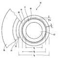
- FIG. 1is a cross-sectional view of the preferred embodiment of the optical fiber of the present invention
- FIG. 2is a cross-sectional view of the preferred embodiment juxtaposed with its refractive index profile
- FIG. 3is a longitudinal cross-sectional view thereof
- FIG. 4is a schematic diagram of a laser cutting device including the preferred optical fiber as the delivery fiber from a fiber laser source to the work area;
- FIG. 5is a schematic diagram of a fiber laser including the preferred optical fiber as the gain medium
- FIG. 6is a schematic diagram of a fiber amplifier including the preferred optical fiber as the gain medium
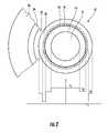
- FIG. 7is a cross-sectional view of a second embodiment of the optical fiber of the present invention having a dual layer of air holes;
- FIG. 8is a cross-sectional view of a third embodiment having a very low refractive index material.
- FIG. 9is a cross-sectional view of a fourth embodiment of the optical fiber of the present invention with a core having a refractive index with a W-profile.
- the preferred embodiment of the optical fiber of the present inventionis illustrated and generally at 10 .
- the fiber 10comprises a photonic crystal fiber with an air hole cladding layer.
- photonic crystal fibers with hole structuresare known in the art.
- Photonic crystal fibersare generally constructed from undoped silica glass. As noted above, guiding is provided by spaced hole structures within the crystal structure of the fiber. Selected portions of the silica glass may contain doping to vary the refractive index.
- the optical fiber 10 of the present inventionincludes a large diameter core (up to 60 ⁇ m) 12 , and a first cladding 14 wherein the difference between refractive index in the core 12 and the first cladding 14 is very small ( ⁇ n ⁇ 0.002) (low contrast boundary), thus providing a very low numerical aperture core (NA between 0.02 and 0.06).
- the fiber 10further has a second cladding 16 , preferably a layer of air holes 18 , having a very low refractive index as compared to the core 12 and first cladding 14 (high contrast) such that the first cladding 14 has a relatively high numerical aperture (NA>0.4).
- NA>0.4numerical aperture
- the small change in refractive index between the core 12 and first cladding 14 combined with a large change in refractive index between the first cladding 14 and second cladding 16provides a significantly improved single mode holding waveguide for low loss transmission and amplification of single-mode high-power continuous wave and/or pulsed laser power.
- the large mode field core 12has a diameter d 1 and the first cladding 14 has a diameter d 2 , wherein the ratio of the diameter of the large mode field core to that of the first cladding is effectively less than 2 and more preferably between about 1.3 and about 1.6.
- the fiber 10 of the present inventioncan be constructed with a core diameter d 1 of preferably between about 20 ⁇ m and 60 ⁇ m. By providing an effective core diameter of up to 60 ⁇ m, a mode field area of up to 2800 ⁇ m 2 may be provided. This is a factor of 2 times better than fibers of the prior art.
- the corehas a diameter of approximately 60 ⁇ m and the first cladding 14 has a diameter of approximately 110 ⁇ m.
- the fiber 10further preferably comprises a third cladding 20 having a diameter d 3 , wherein the diameter d 3 is preferably at least 1.5 times the diameter d 2 (d 3 >1.5d 2 ).
- cladding 20is illustrated as having a diameter d 3 of approximately 1.5 times d 2 . It is contemplated within the scope of the invention that d 3 could be as large as 5 times d 2 .
- the illustrated embodimentsare not drawn to scale and are not intended to limit the invention.
- the fiberfurther includes a fourth cladding 22 , a fifth cladding 24 and an outer protective jacket 26 .
- the fourth and fifth claddingsare optional and are only illustrated as an exemplary embodiment.
- the large mode area core 12has an effective refractive index n 1 .
- the large mode area core 12is formed from silica glass, which is slightly doped to raise the refractive index just above that of the first cladding 14 .
- the large mode area core 12may be doped for example, with elements from the group comprising P, Ge, F, B, Y, or Al. Other dopants known in the art could be substituted depending on the desired characteristics or application the optical fiber 10 will be applied (for example, optimizing for a specific transmission wavelength ⁇ ).
- the core 12may also be doped with rare earth ions such as lanthanide elements like Yb, Nd, Er, Tm or Ho to provide active amplification in the fiber.
- rare earth ionssuch as lanthanide elements like Yb, Nd, Er, Tm or Ho to provide active amplification in the fiber.
- Such active fiberswould be highly effective for use in fiber lasers and amplifiers.
- the first, or inner, cladding 14has an effective refractive index n 2 , which is just slightly lower than the refractive index n 1 of the large mode area core 12 to create an effective numerical aperture (NA 1 ) of between about 0.02 and 0.06.
- the first cladding 14is also preferably formed of silica glass, which may also be doped to obtain the desired refractive index n 2 and numerical aperture (NA 1 ) for the waveguide.
- the critical aspect of the inventionis that the change ( ⁇ ) in refractive index between the core 12 and the first cladding 14 be very small ( ⁇ n ⁇ 0.002) to create a small numerical aperture.
- undoped silica glasshas a refractive index of about 1.450. If the first cladding is undoped silica, the core 12 would be slightly doped to raise the refractive index to about 1.451.
- a second cladding layer 16surrounds the first cladding layer 14 .
- the second cladding 16is formed by a circular ring of coaxial channels 18 spaced uniformly around the first cladding 14 at a pitch s, each coaxial channel having a cross-sectional dimension W (as seen in FIG. 1 ).
- the pitch sis preferably selected to be less than two times the transmission wavelength ⁇ .
- the cross-sectional dimension Wis defined as the largest cross-sectional feature of the hole 18 .
- the dimension W of the coaxial channels 18is less than five times the transmission wavelength ⁇ .
- the holes 18are slightly oblong, and thus have one cross-sectional dimension greater than the other.
- the coaxial channel cladding layer 16has an effective refractive index n 3 , which is much less than the refractive index n 2 of the inner cladding, and preferably n 3 is less than 1.3.
- n 3is much less than the refractive index (high contrast) cladding structure
- NA 2numerical aperture
- the coaxial channels 18are filled with air, however, other gasses may be used.
- the channels 18may also be formed so as to have a vacuum.
- this arrangement of cladding layers around a large mode area coredefines a waveguide wherein the fundamental mode field of the light emission is substantially confined to the large mode area core.
- the third cladding layer 20has a refractive index n 4 wherein n 4 >n 3 .
- the third cladding 20is also preferably a silica glass.
- the thickness of the third cladding 20is about 10-30 ⁇ m, although the exact thickness will depend on the material used and the desired fiber characteristics, and further must conform to the desired diameter characteristic d 3 >1.5 d 2 , as discussed hereinabove.
- Protective jacket 26surrounds the fiber and provides mechanical strength and protection to the optical fiber of the present invention.
- the jacket 26will generally have a thickness of approximately 100 ⁇ m.
- Cladding layers 22 , 24 and the jacket 26comprise conventional cladding materials, which are well known in the art, and the selection of materials and dimensions for these layers is not considered to be critical to the invention outside of the given parameters stated above.
- the optical fiber of the present inventionincludes end facets 28 , 30 located at each end of the optical fiber.
- the end facets 28seal the open ends of the coaxial channels 18 and are preferably less then 100 ⁇ m in thickness.
- the optical fiber of the present inventionis used as a delivery fiber 10 with one end thereof coupled to a fiber laser source 32 .
- a beam expander 34is connected to the opposite end of the delivery fiber for focusing the emission at the worksite.
- the beam expander 34is preferably a cylindrical, conical or multi-step cylindrical conical shaped piece of silica glass that lacks a core.
- the beam expandermay also include an output facet, which may be flat or lensed as desired.
- the output facetmay also be coated with an anti-reflective coating to prevent or reduce back-reflections of the emission thereby preventing possible damage to the fiber laser source.
- optical fiber of the presentcould also be incorporated for use in a fiber laser assembly (as shown in FIG. 5 ) and/or in an amplifier assembly (as shown in FIG. 6 ).
- a fiber laser assembly 100comprises an active fiber 10 a in which the core 12 a , which is doped with a rare earth ion, such as Ytterbium.
- Two reflective structures 102are provided at opposing ends of the optical fiber 10 a to define a lasing cavity therebetween.
- fiber Bragg gratingswould be used for the reflective structures 102 .
- a pump light source 104multimode or single mode
- ⁇corresponding to the absorption spectrum of the dopant, e.g. ytterbium
- an amplifier assembly 200comprises an active fiber 10 b , which is doped with a rare earth ion, such as erbium (Erbium Doped Fiber Amplifier).
- a transmission fiber 202is coupled to the input and output ends of the optical fiber 10 b .
- Transmission fiber 202carries a transmission signal having a wavelength ⁇ t .
- Coupled to the optical fiber 10 bis a pump light source 204 having a wavelength ⁇ p corresponding to the absorption spectrum of the core dopant, e.g. erbium.
- the pump lightexcites the dopant and causes it to emit light in the same wavelength range as the transmission signal thereby boosting or amplifying the transmission light signal.
- a second embodiment of the optical fiber of the present inventionis shown generally at 300 .
- the second embodimentis essentially identical to the first embodiment 10 with the exception that the second cladding layer 16 comprises two concentric rings of coaxial channels 18 .
- the preferred embodiments of the inventionare constructed as photonic crystal fibers that provide a high-contrast coaxial air channel layer having a very low index of refraction.
- itis the relative proportions of the refractive index between the core and first cladding, first cladding and second cladding, and second cladding and third cladding that provide the present fiber with its unique characteristics.
- the Applicantcontemplates that a fiber with similar operational characteristics can be formed using a conventional second cladding layer 16 formed from a solid material, but having a very low index of refraction.
- an alternative embodiment of the inventionis indicated at 400 in FIG. 8 having a second cladding layer shown as a solid layer 16 a .
- Such a fibercould be formed from a silica glass or other polymer materials.
- the third embodimenthas the same dimensional and operational characteristics as the preferred embodiment.
- a fourth embodiment of the optical fiber of the present inventionis shown generally at 500 .
- the fourth embodimentincludes a large mode area core region 12 , a first cladding 14 and a second cladding 16 .
- the large mode area core region 12has a refractive index step that creates a near W-shaped refractive index profile.
- the present inventionprovides a unique optical fiber construction that is particularly suited for high-power multi-kilowatt single mode fiber lasers, and multi-kilowatt power transmission fibers.
- the present fiberallows high-power, robust single mode propagation of light in a fiber waveguide, with little or no leakage even with a very tight bend radius.
- the many benefits provided by this fiberare an order of magnitude improvement of peak power with diffraction limited beam quality, an order of magnitude improvement in length of high-power single mode transmission cables, a more reliable, cost effective signal coupling due to the larger fiber effective area, a more manageable cable construction because of tighter bending radii and higher cable reliability because of low loss transmission.
Landscapes
- Physics & Mathematics (AREA)
- General Physics & Mathematics (AREA)
- Optics & Photonics (AREA)
- Lasers (AREA)
Abstract
Description
Claims (34)
Priority Applications (2)
| Application Number | Priority Date | Filing Date | Title |
|---|---|---|---|
| US11/611,239US7283714B1 (en) | 2006-12-15 | 2006-12-15 | Large mode area fiber for low-loss transmission and amplification of single mode lasers |
| PCT/US2007/020541WO2008076162A2 (en) | 2006-12-15 | 2007-09-21 | Large mode area fiber for low-loss transmission and amplification of single mode lasers |
Applications Claiming Priority (1)
| Application Number | Priority Date | Filing Date | Title |
|---|---|---|---|
| US11/611,239US7283714B1 (en) | 2006-12-15 | 2006-12-15 | Large mode area fiber for low-loss transmission and amplification of single mode lasers |
Publications (1)
| Publication Number | Publication Date |
|---|---|
| US7283714B1true US7283714B1 (en) | 2007-10-16 |
Family
ID=38577851
Family Applications (1)
| Application Number | Title | Priority Date | Filing Date |
|---|---|---|---|
| US11/611,239ActiveUS7283714B1 (en) | 2006-12-15 | 2006-12-15 | Large mode area fiber for low-loss transmission and amplification of single mode lasers |
Country Status (2)
| Country | Link |
|---|---|
| US (1) | US7283714B1 (en) |
| WO (1) | WO2008076162A2 (en) |
Cited By (33)
| Publication number | Priority date | Publication date | Assignee | Title |
|---|---|---|---|---|
| US20080056654A1 (en)* | 2006-08-31 | 2008-03-06 | Scott Robertson Bickham | Low bend loss single mode optical fiber |
| WO2008110668A1 (en)* | 2007-03-15 | 2008-09-18 | Liekki Oy | Optical fiber structure and a method of producing thereof |
| US20080279515A1 (en)* | 2007-05-07 | 2008-11-13 | Scott Robertson Bickham | Optical fiber containing alkali metal oxide |
| US20090123121A1 (en)* | 2006-09-20 | 2009-05-14 | Imra America, Inc. | Rare earth doped and large effective area optical fibers for fiber lasers and amplifiers |
| US20090218326A1 (en)* | 2006-02-03 | 2009-09-03 | L'air Liquide Societe Anonyme Pour L'eploitation Des Procedes Georges Cladue | Cutting method using a laser having at least one ytterbium-based fiber, in which at least the power of the laser source, the diameter of the focused beam and the beam quality factor are controlled |
| US7587111B2 (en) | 2006-04-10 | 2009-09-08 | Draka Comteq B.V. | Single-mode optical fiber |
| US20090279835A1 (en)* | 2008-05-06 | 2009-11-12 | Draka Comteq B.V. | Single-Mode Optical Fiber Having Reduced Bending Losses |
| US7623747B2 (en) | 2005-11-10 | 2009-11-24 | Draka Comteq B.V. | Single mode optical fiber |
| US20100183272A1 (en)* | 2009-01-19 | 2010-07-22 | Eisuke Sasaoka | Optical fiber |
| US20100195965A1 (en)* | 2009-01-20 | 2010-08-05 | Eisuke Sasaoka | Optical communication system and arrangement converter |
| US7773848B2 (en) | 2008-07-30 | 2010-08-10 | Corning Incorporated | Low bend loss single mode optical fiber |
| US20100215326A1 (en)* | 2008-10-17 | 2010-08-26 | Zediker Mark S | Optical Fiber Cable for Transmission of High Power Laser Energy Over Great Distances |
| US20100214650A1 (en)* | 2009-02-26 | 2010-08-26 | Cubic Corporation | Butterfly laser |
| US20100294745A1 (en)* | 2009-05-20 | 2010-11-25 | Ipg Photonics Corporation | Laser Machining Process and Apparatus |
| US20110069723A1 (en)* | 2008-12-04 | 2011-03-24 | Imra America, Inc. | Highly rare-earth-doped optical fibers for fiber lasers and amplifiers |
| US20110222828A1 (en)* | 2010-03-10 | 2011-09-15 | Sumitomo Electric Industries, Ltd. | Multi-core optical fiber |
| US8145027B2 (en) | 2007-11-09 | 2012-03-27 | Draka Comteq, B.V. | Microbend-resistant optical fiber |
| US8447156B2 (en) | 2009-01-19 | 2013-05-21 | Sumitomo Electric Industries, Ltd. | Multi-core optical fiber |
| WO2013151691A1 (en)* | 2012-04-06 | 2013-10-10 | 3M Innovative Properties Company | Tools for making retroreflective articles |
| US20130272670A1 (en)* | 2010-12-23 | 2013-10-17 | Silvio Frigerio | Low macrobending loss single-mode optical fibre |
| EP2378321A4 (en)* | 2008-12-15 | 2014-07-30 | Furukawa Electric Co Ltd | Holey fiber |
| EP2822112A1 (en)* | 2013-03-15 | 2015-01-07 | OFS Fitel, LLC (a Delaware Limited Liability Company) | High-power double-cladding-pumped (DC) erbium-doped fiber amplifier (EDFA) |
| US20150131145A1 (en)* | 2012-05-21 | 2015-05-14 | V-Gen Ltd. | Generation of narrow line width high power optical pulses |
| JP2020154160A (en)* | 2019-03-20 | 2020-09-24 | 三菱電線工業株式会社 | Laser beam transmission optical fiber |
| WO2020248552A1 (en)* | 2019-06-12 | 2020-12-17 | 烽火通信科技股份有限公司 | Ultra-low attenuation large effective area single-mode optical fibre |
| DE102019212360A1 (en)* | 2019-08-19 | 2021-02-25 | Trumpf Werkzeugmaschinen Gmbh + Co. Kg | Method of flame cutting by means of a laser beam |
| CN113492261A (en)* | 2020-03-19 | 2021-10-12 | 西安中科汇纤光电科技有限公司 | Laser processing device and manufacturing method of nonferrous metal |
| CN114137653A (en)* | 2021-10-26 | 2022-03-04 | 华南师范大学 | A photonic crystal fiber that actively filters out higher-order radial modes |
| CN114488387A (en)* | 2022-01-23 | 2022-05-13 | 武汉安扬激光技术股份有限公司 | Single-mode optical fiber for inhibiting stimulated Brillouin scattering |
| JP2022079887A (en)* | 2020-11-17 | 2022-05-27 | 三菱電線工業株式会社 | Optical fiber for blue laser light transmission |
| CN116202743A (en)* | 2023-03-15 | 2023-06-02 | 江西天孚科技有限公司 | Multichannel laser assembly testing arrangement |
| CN116974002A (en)* | 2023-07-13 | 2023-10-31 | 淮阴工学院 | Double-ring photonic crystal fiber for reducing mode coupling and improvement method thereof |
| CN119556465A (en)* | 2025-01-22 | 2025-03-04 | 中国人民解放军国防科技大学 | Gain fiber refractive index distribution optimization design method, gain fiber and its application |
Citations (9)
| Publication number | Priority date | Publication date | Assignee | Title |
|---|---|---|---|---|
| US4815079A (en) | 1987-12-17 | 1989-03-21 | Polaroid Corporation | Optical fiber lasers and amplifiers |
| US20020164137A1 (en) | 2001-01-25 | 2002-11-07 | Johnson Steven G. | Low-loss photonic crystal waveguide having large core radius |
| US20020176676A1 (en) | 2001-01-25 | 2002-11-28 | Johnson Steven G. | Photonic crystal optical waveguides having tailored dispersion profiles |
| US20040086245A1 (en)* | 2002-03-19 | 2004-05-06 | Farroni Julia A. | Optical fiber |
| US20040096172A1 (en) | 2002-11-15 | 2004-05-20 | Alcatel | Polarization retaining photonic crystal fibers |
| US20040240816A1 (en) | 2003-05-29 | 2004-12-02 | Sung-Koog Oh | Photonic crystal fiber preform and photonic crystal fiber manufactured using the same |
| US20050175059A1 (en) | 2002-04-24 | 2005-08-11 | Alfa-Light, Inc. | Feedback stabilized multimode and method of stabilizing a multimode laser |
| US7050686B2 (en)* | 2004-08-05 | 2006-05-23 | Nufern | Fiber optic article with inner region |
| US7062137B2 (en)* | 2004-08-05 | 2006-06-13 | Nufern | Fiber optic article including fluorine |
Family Cites Families (2)
| Publication number | Priority date | Publication date | Assignee | Title |
|---|---|---|---|---|
| CA2157828C (en)* | 1994-09-13 | 2003-02-11 | Youichi Akasaka | Dispersion compensating optical fiber for wavelength division multiplex transmission |
| US7787729B2 (en)* | 2005-05-20 | 2010-08-31 | Imra America, Inc. | Single mode propagation in fibers and rods with large leakage channels |
- 2006
- 2006-12-15USUS11/611,239patent/US7283714B1/enactiveActive
- 2007
- 2007-09-21WOPCT/US2007/020541patent/WO2008076162A2/enactiveApplication Filing
Patent Citations (10)
| Publication number | Priority date | Publication date | Assignee | Title |
|---|---|---|---|---|
| US4815079A (en) | 1987-12-17 | 1989-03-21 | Polaroid Corporation | Optical fiber lasers and amplifiers |
| US20020164137A1 (en) | 2001-01-25 | 2002-11-07 | Johnson Steven G. | Low-loss photonic crystal waveguide having large core radius |
| US20020176676A1 (en) | 2001-01-25 | 2002-11-28 | Johnson Steven G. | Photonic crystal optical waveguides having tailored dispersion profiles |
| US20040086245A1 (en)* | 2002-03-19 | 2004-05-06 | Farroni Julia A. | Optical fiber |
| US7116887B2 (en)* | 2002-03-19 | 2006-10-03 | Nufern | Optical fiber |
| US20050175059A1 (en) | 2002-04-24 | 2005-08-11 | Alfa-Light, Inc. | Feedback stabilized multimode and method of stabilizing a multimode laser |
| US20040096172A1 (en) | 2002-11-15 | 2004-05-20 | Alcatel | Polarization retaining photonic crystal fibers |
| US20040240816A1 (en) | 2003-05-29 | 2004-12-02 | Sung-Koog Oh | Photonic crystal fiber preform and photonic crystal fiber manufactured using the same |
| US7050686B2 (en)* | 2004-08-05 | 2006-05-23 | Nufern | Fiber optic article with inner region |
| US7062137B2 (en)* | 2004-08-05 | 2006-06-13 | Nufern | Fiber optic article including fluorine |
Cited By (74)
| Publication number | Priority date | Publication date | Assignee | Title |
|---|---|---|---|---|
| US20100067859A1 (en)* | 2005-11-10 | 2010-03-18 | Draka Comteq B.V. | Single Mode Optical Fiber |
| US7995889B2 (en) | 2005-11-10 | 2011-08-09 | Draka Comteq, B.V. | Single mode optical fiber |
| US8837889B2 (en) | 2005-11-10 | 2014-09-16 | Draka Comteq, B.V. | Single mode optical fiber |
| US7623747B2 (en) | 2005-11-10 | 2009-11-24 | Draka Comteq B.V. | Single mode optical fiber |
| US8278591B2 (en)* | 2006-02-03 | 2012-10-02 | L'air Liquide Societe Anonyme Pour L'etude Et L'exploitation Des Procedes Georges Claude | Cutting method using a laser having at least one ytterbium-based fiber, in which at least the power of the laser source, the diameter of the focused beam and the beam quality factor are controlled |
| US20090218326A1 (en)* | 2006-02-03 | 2009-09-03 | L'air Liquide Societe Anonyme Pour L'eploitation Des Procedes Georges Cladue | Cutting method using a laser having at least one ytterbium-based fiber, in which at least the power of the laser source, the diameter of the focused beam and the beam quality factor are controlled |
| US8103143B2 (en) | 2006-04-10 | 2012-01-24 | Draka Comteq, B.V. | Single-mode optical fiber |
| US7587111B2 (en) | 2006-04-10 | 2009-09-08 | Draka Comteq B.V. | Single-mode optical fiber |
| US7899293B2 (en) | 2006-04-10 | 2011-03-01 | Draka Comteq, B.V. | Single-mode optical fiber |
| US7620282B2 (en)* | 2006-08-31 | 2009-11-17 | Corning Incorporated | Low bend loss single mode optical fiber |
| US7903917B2 (en)* | 2006-08-31 | 2011-03-08 | Corning Incorporated | Low bend loss single mode optical fiber |
| US20080056654A1 (en)* | 2006-08-31 | 2008-03-06 | Scott Robertson Bickham | Low bend loss single mode optical fiber |
| US9151889B2 (en) | 2006-09-20 | 2015-10-06 | Imra America, Inc. | Rare earth doped and large effective area optical fibers for fiber lasers and amplifiers |
| US8213758B2 (en) | 2006-09-20 | 2012-07-03 | Imra America, Inc. | Rare earth doped and large effective area optical fibers for fiber lasers and amplifiers |
| US8542968B2 (en) | 2006-09-20 | 2013-09-24 | Imra America, Inc. | Rare earth doped and large effective area optical fibers for fiber lasers and amplifiers |
| US20090123121A1 (en)* | 2006-09-20 | 2009-05-14 | Imra America, Inc. | Rare earth doped and large effective area optical fibers for fiber lasers and amplifiers |
| US20100329618A1 (en)* | 2006-09-20 | 2010-12-30 | Imra America, Inc. | Rare earth doped and large effective area optical fibers for fiber lasers and amplifiers |
| WO2008110668A1 (en)* | 2007-03-15 | 2008-09-18 | Liekki Oy | Optical fiber structure and a method of producing thereof |
| US8620126B2 (en) | 2007-03-15 | 2013-12-31 | Nlight Oy | Optical fiber structure and a method of producing thereof |
| US20100220965A1 (en)* | 2007-03-15 | 2010-09-02 | Liekki Oy | Optical fiber structure and a method of producing thereof |
| US20080279515A1 (en)* | 2007-05-07 | 2008-11-13 | Scott Robertson Bickham | Optical fiber containing alkali metal oxide |
| US7844155B2 (en)* | 2007-05-07 | 2010-11-30 | Corning Incorporated | Optical fiber containing alkali metal oxide |
| US8385705B2 (en) | 2007-11-09 | 2013-02-26 | Draka Comteq, B.V. | Microbend-resistant optical fiber |
| US8145027B2 (en) | 2007-11-09 | 2012-03-27 | Draka Comteq, B.V. | Microbend-resistant optical fiber |
| US20090279835A1 (en)* | 2008-05-06 | 2009-11-12 | Draka Comteq B.V. | Single-Mode Optical Fiber Having Reduced Bending Losses |
| US7889960B2 (en) | 2008-05-06 | 2011-02-15 | Draka Comteq B.V. | Bend-insensitive single-mode optical fiber |
| US8428414B2 (en) | 2008-05-06 | 2013-04-23 | Draka Comteq, B.V. | Single-mode optical fiber having reduced bending losses |
| US8131125B2 (en) | 2008-05-06 | 2012-03-06 | Draka Comteq, B.V. | Bend-insensitive single-mode optical fiber |
| US8145025B2 (en) | 2008-05-06 | 2012-03-27 | Draka Comteq, B.V. | Single-mode optical fiber having reduced bending losses |
| US7773848B2 (en) | 2008-07-30 | 2010-08-10 | Corning Incorporated | Low bend loss single mode optical fiber |
| US9347271B2 (en)* | 2008-10-17 | 2016-05-24 | Foro Energy, Inc. | Optical fiber cable for transmission of high power laser energy over great distances |
| US20100215326A1 (en)* | 2008-10-17 | 2010-08-26 | Zediker Mark S | Optical Fiber Cable for Transmission of High Power Laser Energy Over Great Distances |
| US20160299304A1 (en)* | 2008-10-17 | 2016-10-13 | Foro Energy, Inc. | Optical fiber cable for transmission of high power laser energy over great distances |
| US10001612B2 (en)* | 2008-10-17 | 2018-06-19 | Foro Energy, Inc. | Optical fiber cable for transmission of high power laser energy over great distances |
| US20110069723A1 (en)* | 2008-12-04 | 2011-03-24 | Imra America, Inc. | Highly rare-earth-doped optical fibers for fiber lasers and amplifiers |
| US8902493B2 (en) | 2008-12-04 | 2014-12-02 | Imra America, Inc. | Highly rare-earth-doped optical fibers for fiber lasers and amplifiers |
| US8498046B2 (en) | 2008-12-04 | 2013-07-30 | Imra America, Inc. | Highly rare-earth-doped optical fibers for fiber lasers and amplifiers |
| EP2378321A4 (en)* | 2008-12-15 | 2014-07-30 | Furukawa Electric Co Ltd | Holey fiber |
| US8655131B2 (en) | 2009-01-19 | 2014-02-18 | Sumitomo Electric Industries, Ltd. | Multi-core optical fiber |
| US20100183272A1 (en)* | 2009-01-19 | 2010-07-22 | Eisuke Sasaoka | Optical fiber |
| EP2209029A3 (en)* | 2009-01-19 | 2010-08-04 | Sumitomo Electric Industries, Ltd. | Optical fiber |
| US8687931B2 (en) | 2009-01-19 | 2014-04-01 | Sumitomo Electric Industries, Ltd. | Optical fiber |
| US8447156B2 (en) | 2009-01-19 | 2013-05-21 | Sumitomo Electric Industries, Ltd. | Multi-core optical fiber |
| US8320724B2 (en) | 2009-01-20 | 2012-11-27 | Sumitomo Electric Industries, Ltd. | Optical communication system and arrangement converter |
| US20100195965A1 (en)* | 2009-01-20 | 2010-08-05 | Eisuke Sasaoka | Optical communication system and arrangement converter |
| US8520298B2 (en)* | 2009-02-26 | 2013-08-27 | Cubic Corporation | Tightly coiled amplifying optical fiber with reduced mode distortion |
| US20100214650A1 (en)* | 2009-02-26 | 2010-08-26 | Cubic Corporation | Butterfly laser |
| US20100294745A1 (en)* | 2009-05-20 | 2010-11-25 | Ipg Photonics Corporation | Laser Machining Process and Apparatus |
| US20110222828A1 (en)* | 2010-03-10 | 2011-09-15 | Sumitomo Electric Industries, Ltd. | Multi-core optical fiber |
| EP2369376A3 (en)* | 2010-03-10 | 2012-10-10 | Sumitomo Electric Industries, Ltd. | Multi-core optical fiber |
| US20130272670A1 (en)* | 2010-12-23 | 2013-10-17 | Silvio Frigerio | Low macrobending loss single-mode optical fibre |
| US9279935B2 (en)* | 2010-12-23 | 2016-03-08 | Prysmian S.P.A. | Low macrobending loss single-mode optical fibre |
| KR20150008081A (en)* | 2012-04-06 | 2015-01-21 | 쓰리엠 이노베이티브 프로퍼티즈 캄파니 | Tools for making retroreflective articles |
| CN104379329A (en)* | 2012-04-06 | 2015-02-25 | 3M创新有限公司 | Tools for making retroreflective articles |
| US9884447B2 (en) | 2012-04-06 | 2018-02-06 | 3M Innovative Properties Company | Tools for making retroreflective articles |
| JP2015520404A (en)* | 2012-04-06 | 2015-07-16 | スリーエム イノベイティブ プロパティズ カンパニー | Tool for making retroreflective articles |
| WO2013151691A1 (en)* | 2012-04-06 | 2013-10-10 | 3M Innovative Properties Company | Tools for making retroreflective articles |
| CN104379329B (en)* | 2012-04-06 | 2018-05-18 | 3M创新有限公司 | It is used to prepare the instrument of counter-reflective products |
| US20150131145A1 (en)* | 2012-05-21 | 2015-05-14 | V-Gen Ltd. | Generation of narrow line width high power optical pulses |
| US9472919B2 (en)* | 2012-05-21 | 2016-10-18 | V-Gen Ltd. | Generation of narrow line width high power optical pulses |
| EP2822112A1 (en)* | 2013-03-15 | 2015-01-07 | OFS Fitel, LLC (a Delaware Limited Liability Company) | High-power double-cladding-pumped (DC) erbium-doped fiber amplifier (EDFA) |
| JP2020154160A (en)* | 2019-03-20 | 2020-09-24 | 三菱電線工業株式会社 | Laser beam transmission optical fiber |
| EP3907538A4 (en)* | 2019-06-12 | 2022-10-05 | Fiberhome Telecommunication Technologies Co., Ltd | SINGLE MODE FIBER OPTIC WITH EXTREMELY LOW ATTENUATION AND LARGE EFFECTIVE AREA |
| WO2020248552A1 (en)* | 2019-06-12 | 2020-12-17 | 烽火通信科技股份有限公司 | Ultra-low attenuation large effective area single-mode optical fibre |
| DE102019212360A1 (en)* | 2019-08-19 | 2021-02-25 | Trumpf Werkzeugmaschinen Gmbh + Co. Kg | Method of flame cutting by means of a laser beam |
| EP4017674B1 (en) | 2019-08-19 | 2023-11-22 | TRUMPF Werkzeugmaschinen SE + Co. KG | Method for flame cutting by means of a laser beam |
| CN113492261A (en)* | 2020-03-19 | 2021-10-12 | 西安中科汇纤光电科技有限公司 | Laser processing device and manufacturing method of nonferrous metal |
| JP2022079887A (en)* | 2020-11-17 | 2022-05-27 | 三菱電線工業株式会社 | Optical fiber for blue laser light transmission |
| CN114137653A (en)* | 2021-10-26 | 2022-03-04 | 华南师范大学 | A photonic crystal fiber that actively filters out higher-order radial modes |
| CN114488387A (en)* | 2022-01-23 | 2022-05-13 | 武汉安扬激光技术股份有限公司 | Single-mode optical fiber for inhibiting stimulated Brillouin scattering |
| CN114488387B (en)* | 2022-01-23 | 2024-03-26 | 武汉安扬激光技术股份有限公司 | Single mode fiber capable of inhibiting stimulated Brillouin scattering |
| CN116202743A (en)* | 2023-03-15 | 2023-06-02 | 江西天孚科技有限公司 | Multichannel laser assembly testing arrangement |
| CN116974002A (en)* | 2023-07-13 | 2023-10-31 | 淮阴工学院 | Double-ring photonic crystal fiber for reducing mode coupling and improvement method thereof |
| CN119556465A (en)* | 2025-01-22 | 2025-03-04 | 中国人民解放军国防科技大学 | Gain fiber refractive index distribution optimization design method, gain fiber and its application |
Also Published As
| Publication number | Publication date |
|---|---|
| WO2008076162A2 (en) | 2008-06-26 |
| WO2008076162A3 (en) | 2008-08-21 |
Similar Documents
| Publication | Publication Date | Title |
|---|---|---|
| US7283714B1 (en) | Large mode area fiber for low-loss transmission and amplification of single mode lasers | |
| US8731358B2 (en) | Multi-cladding fiber | |
| US7835608B2 (en) | Method and apparatus for optical delivery fiber having cladding with absorbing regions | |
| US10353144B2 (en) | Glass large-core optical fibers | |
| US20080144673A1 (en) | Fiber laser with large mode area fiber | |
| US8755660B1 (en) | Method and apparatus for compensating for and using mode-profile distortions caused by bending optical fibers | |
| US7924500B1 (en) | Micro-structured fiber profiles for mitigation of bend-loss and/or mode distortion in LMA fiber amplifiers, including dual-core embodiments | |
| EP1933183B1 (en) | Large-mode-area, multimode, hybrid optical fibers and devices using same | |
| US6987783B2 (en) | Three-level air-clad rare-earth doped fiber laser/amplifier | |
| US5892615A (en) | Output power enhancement in optical fiber lasers | |
| EP1988412A2 (en) | Mode-field resizing in optical fibers | |
| US8045259B2 (en) | Active optical fibers with wavelength-selective filtering mechanism, method of production and their use | |
| EP1443347A2 (en) | Single mode optical fibre | |
| WO2010146792A1 (en) | Multiclad optical fiber, optical fiber module, fiber laser, and fiber amplifier | |
| JP3786010B2 (en) | Optical fiber | |
| WO2012043603A1 (en) | Solid photonic band gap fiber, and fiber module, fiber amp, and fiber laser employing solid photonic band gap fiber | |
| US6904219B1 (en) | Ultra high-power continuous wave planar waveguide amplifiers and lasers | |
| WO2006099017A1 (en) | Large mode-area microstructured optical fiber | |
| JP4959314B2 (en) | Rare earth doped large mode area multimode optical fiber and device using the same | |
| EP2005538A2 (en) | An optical fiber, a fiber laser, a fiber amplifier and articles comprising such elements | |
| US7120339B2 (en) | Polarization-dependent optical fibre amplifier | |
| Abdou‐Ahmed et al. | Optical Fibres for High‐Power Single‐Mode Beam Delivery: Find the best fitting fibre for your application! | |
| Aleshkina et al. | Spectrally selective optical loss in fibers with high-index rods embedded into silica cladding | |
| RU2803143C1 (en) | Active fibre light guide with various cross-section area, method for its manufacture (versions) and optical signal amplifier on its basis | |
| US20230231355A1 (en) | Active optical fiber with variable cross-section area, method of production the same (variants) and an optical signal amplifier based on it |
Legal Events
| Date | Code | Title | Description |
|---|---|---|---|
| FEPP | Fee payment procedure | Free format text:PAYOR NUMBER ASSIGNED (ORIGINAL EVENT CODE: ASPN); ENTITY STATUS OF PATENT OWNER: LARGE ENTITY | |
| AS | Assignment | Owner name:IPG PHOTONICS CORPORATION, MASSACHUSETTS Free format text:ASSIGNMENT OF ASSIGNORS INTEREST;ASSIGNOR:GAPONTSEZ, VALENTIN P.;REEL/FRAME:018644/0218 Effective date:20061212 | |
| AS | Assignment | Owner name:IPG PHOTONICS CORPORATION, MASSACHUSETTS Free format text:ASSIGNMENT OF ASSIGNORS INTEREST;ASSIGNORS:GASPONTSEV, VALENTIN P.;VYATKIN, MIKHAIL;REEL/FRAME:018974/0688;SIGNING DATES FROM 20070226 TO 20070303 | |
| AS | Assignment | Owner name:IPG PHOTONICS CORPORATION, MASSACHUSETTS Free format text:ASSIGNMENT OF ASSIGNORS INTEREST;ASSIGNOR:GRIGORIEV, VLADIMIR;REEL/FRAME:018991/0120 Effective date:20070223 | |
| STCF | Information on status: patent grant | Free format text:PATENTED CASE | |
| REMI | Maintenance fee reminder mailed | ||
| FPAY | Fee payment | Year of fee payment:4 | |
| SULP | Surcharge for late payment | ||
| FEPP | Fee payment procedure | Free format text:PAT HOLDER NO LONGER CLAIMS SMALL ENTITY STATUS, ENTITY STATUS SET TO UNDISCOUNTED (ORIGINAL EVENT CODE: STOL); ENTITY STATUS OF PATENT OWNER: LARGE ENTITY | |
| REFU | Refund | Free format text:REFUND - 7.5 YR SURCHARGE - LATE PMT W/IN 6 MO, SMALL ENTITY (ORIGINAL EVENT CODE: R2555); ENTITY STATUS OF PATENT OWNER: LARGE ENTITY Free format text:REFUND - PAYMENT OF MAINTENANCE FEE, 8TH YR, SMALL ENTITY (ORIGINAL EVENT CODE: R2552); ENTITY STATUS OF PATENT OWNER: LARGE ENTITY | |
| REMI | Maintenance fee reminder mailed | ||
| FPAY | Fee payment | Year of fee payment:8 | |
| SULP | Surcharge for late payment | Year of fee payment:7 | |
| MAFP | Maintenance fee payment | Free format text:PAYMENT OF MAINTENANCE FEE, 12TH YEAR, LARGE ENTITY (ORIGINAL EVENT CODE: M1553); ENTITY STATUS OF PATENT OWNER: LARGE ENTITY Year of fee payment:12 |