US7283666B2 - Digital image exposure correction - Google Patents
Digital image exposure correctionDownload PDFInfo
- Publication number
- US7283666B2 US7283666B2US10/375,440US37544003AUS7283666B2US 7283666 B2US7283666 B2US 7283666B2US 37544003 AUS37544003 AUS 37544003AUS 7283666 B2US7283666 B2US 7283666B2
- Authority
- US
- United States
- Prior art keywords
- image
- exposure
- transformed
- transformed image
- transforming
- Prior art date
- Legal status (The legal status is an assumption and is not a legal conclusion. Google has not performed a legal analysis and makes no representation as to the accuracy of the status listed.)
- Expired - Lifetime, expires
Links
Images


Classifications
- H—ELECTRICITY
- H04—ELECTRIC COMMUNICATION TECHNIQUE
- H04N—PICTORIAL COMMUNICATION, e.g. TELEVISION
- H04N1/00—Scanning, transmission or reproduction of documents or the like, e.g. facsimile transmission; Details thereof
- H04N1/40—Picture signal circuits
- H04N1/407—Control or modification of tonal gradation or of extreme levels, e.g. background level
- H04N1/4072—Control or modification of tonal gradation or of extreme levels, e.g. background level dependent on the contents of the original
Definitions
- the present inventionrelates to digital image processing and, more particularly, to correcting the exposure of digital images.
- the “exposure” of a digital imagerefers to the quantity of light allowed to act on the image capture sensor; exposure is a product of the intensity (controlled by the aperture and intensity of the illuminant) and the duration (controlled by the shutter speed) of light striking the sensor. Large exposure values will result in brighter images and vice versa. Relying on the original exposure set by the input device (e.g., a digital camera) usually does not yield the best quality for several reasons. For example, a wide variety of picture-taking conditions and scene compositions may make the original exposure quite variable and differ from the preferred exposure.
- input devicestypically have limited dynamic range and therefore err on the side of under-exposing an image to avoid losing information in an image due to clipping.
- underexposed imagesmay appear darker than desired, they tend to retain more information than overexposed images and therefore are amenable to post-acquisition exposure correction to make them more suitable for printing or displaying on an output device.
- output devicesbe equipped to produce properly-exposed renderings from images acquired using a variety of (possibly unknown) image acquisition devices.
- a desktop digital photo printer or a photo-vending kioskmay be capable of receiving digital images acquired using any of a wide variety of digital cameras, scanners, or other input devices under a wide variety of conditions. It is desirable that such a printer or kiosk be capable of correcting the exposure of any images it receives so that such images may be printed with optimal exposures.
- An exposure predictormay be generated based on a set of images for which ground truth data are known.
- An optimal feature setmay be identified that strikes a balance between minimizing prediction error and producing good results across a wide range of images.
- the exposure of an imagemay be corrected by extracting values of the selected optimal features from the image, using the predictor to predict a desired exposure correction for the image, and correcting the exposure of the image by the predicted desired amount.
- a modelthat relates intensity of light in the world to the RGB digits of the digital image.
- This modelcomprises a gamma function that models the response of a typical monitor and a S-shaped curve that allows us to compress the large dynamic range of the world to the small dynamic range of the RGB digit space.
- the exposure of the imagemay then be corrected by employing the inverse of this model to transform the image to logarithmic intensities in the world, adding or subtracting an offset (given by the desired exposure correction) from the image, and then mapping the image back to the RGB digit space using the above model.
- a methodis provided for correcting the exposure of a source image.
- the methodincludes steps of: (A) transforming the source image from an image capture space into a nonlinear intensity space to produce a first transformed image; (B) correcting the exposure of the transformed image in the nonlinear intensity space to produce a corrected transformed image; and (C) transforming the corrected transformed image into the image capture space to produce a second transformed image.
- the step (C)may include steps of: (C)( 1 ) transforming the corrected transformed image into a third transformed image using an S-shaped curve; and (C)( 2 ) transforming the third transformed image into the second transformed image using a gamma function.
- a methodfor processing an image. The method includes steps of: (A) extracting from the image values of at least one feature selected from a set of features including: a thumbnail of the image, a luminance channel of the image, a region of interest in the image, and a subset of the image including a plurality of pixels satisfying an activity threshold; (B) predicting a desired exposure correction of the image based on the extracted feature values; and (C) correcting the exposure of the image by the predicted exposure correction to produce an exposure-corrected image.
- the set of featuresmay include other features instead of or in addition to the features just listed.
- the region of interestmay have the following properties: (1) the average activity within the region is above a predetermined minimum activity threshold; and (2) the absolute logarithm of the ratio of the average luminance of the region to the average luminance of that portion of the image not including the region is the highest such absolute logarithm for a predetermined plurality of regions in the image.
- the region of interestmay have a base size that is proportional to the dimensions of the image, and the dimensions of the region of interest may be proportional to the base size multiplied by a measure of average activity in the image.
- a methodfor selecting a set of features for use in a system for adjusting the exposure of images.
- the methodincludes steps of: (A) placing a set of features in a master feature set M; (B) initializing a current feature set C to a null value; (C) for each feature F in the master set M, performing steps of: ( 1 ) placing the union of the current feature set C and the feature F in a temporary feature set S; ( 2 ) computing a leave-n-out error E for a plurality of images using set S as a feature set; ( 3 ) if the error E is less than a minimum error E MIN , assigning the value of E to E MIN and recording the identity of feature F in a variable F MIN ; (D) if E MIN is less than a global error E G , assigning the value of E MIN to E G , adding the feature F recorded in F MIN to the set C, and deleting the feature F recorded in F MIN from the set M
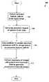
- FIG. 1Ais a flowchart of a method for correcting the exposure of an image according to one embodiment of the present invention
- FIG. 1Bis a flowchart of a method for reducing an image according to one embodiment of the present invention
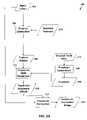
- FIG. 1Cis a flowchart of a method for extracting features from an image according to one embodiment of the present invention.
- FIG. 2Ais a dataflow diagram illustrating operations performed by the method shown in FIG. 1A ;
- FIG. 2Bis a dataflow diagram illustrating operations performed by the method shown in FIG. 1B ;
- FIGS. 2Cis a dataflow diagram illustrating the operations performed by the method shown in FIG. 1C ;
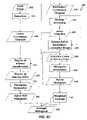
- FIG. 3is a flowchart of a method for identifying a region of interest in an image according to one embodiment of the present invention
- FIG. 4is a flowchart of a method for extracting features from an image according to one embodiment of the present invention.
- FIG. 5is a flowchart of a method for generating a predictor for predicting desired image exposures according to one embodiment of the present invention
- FIG. 6is a dataflow diagram illustrating the operations performed by the method shown in FIG. 5 ;
- FIG. 7Ais a flowchart of a method for generating ground truth data for a set of ground truth images according to one embodiment of the present invention
- FIG. 7Bis a dataflow diagram illustrating the operations performed by the method of FIG. 7A according to one embodiment of the present invention.
- FIG. 7Cis a dataflow diagram illustrating the generation of ground truth data for an image in a ground truth set of images according to one embodiment of the present invention.
- FIG. 7Dis a dataflow diagram illustrating the computation of a prediction error for a test set image according to one embodiment of the present invention.
- FIG. 7Eis a dataflow diagram illustrating the computation of an average prediction error for a plurality of images in a ground truth image set according to one embodiment of the present invention.
- FIG. 8is a flowchart of a method for computing the average prediction error for a plurality of images in a ground truth image set according to one embodiment of the present invention
- FIG. 9is a flowchart of a method for selecting an optimal number and combination of features for use in exposure correction according to one embodiment of the present invention.
- FIG. 10is a graph illustrating a family of exposure adjustment curves for use in exposure correction according to one embodiment of the present invention.
- FIG. 11is a flowchart of a method for applying an exposure correction to an image to produce an exposure-corrected image according to one embodiment of the present invention.
- FIG. 12is a flowchart of a method in which color mapping and exposure correction are integrated according to one embodiment of the present invention.
- the exposure correction algorithm disclosed hereinmay be divided into two parts.
- the first partextracts, from the input image, the values of a set of features that contain the information that is most relevant to the exposure of the image.
- the second partfinds a predictor that operates on the extracted features to generate a predicted exposure correction to apply to the image.
- the predicted exposure correctionis applied to the image to produce an exposure-corrected image.
- the predictormay, for example, be a linear predictor that is chosen so that the error between the predicted exposure and desired exposure of images is minimized in a least square sense.
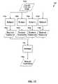
- FIG. 1Aa flowchart is shown of a method 100 for correcting the exposure of an image according to one embodiment of the present invention.
- FIG. 2Aa dataflow diagram 200 is shown which illustrates the operations performed by the method 100 shown in FIG. 1A .
- the method 100operates on an input image 202 ( FIG. 2A ), which may be received from any of a variety of sources such as a digital camera or scanner.
- the input image 202may be represented in any of a variety of formats for representing digital images, such as the JPEG format.
- the method 100extracts from the image 202 the values 208 of a set of selected features 218 (step 106 ).
- the selected features 218may, for example, be identifiers or other descriptors which identify the particular features to be extracted in step 106 . Examples of features that may be extracted in step 106 , and examples of techniques for extracting them, will be described below with respect to FIG. 1B , FIG. 1C , FIG. 2C , FIG. 3 , and FIG. 4 . Techniques that may be used to select the set of features 218 will be described below with respect to FIG. 9 .
- the method 100generates a predictor 216 based on ground truth data 210 for a set of ground truth images (step 108 ). Note that step 108 need not be performed each time the method 100 is performed. Rather, the predictor 216 may be generated once, prior to execution of the method 100 . The generated predictor 216 may then be used each time the method 100 is performed, without the need to perform step 108 . Techniques that may be used to generate the predictor 216 will be described below with respect to FIGS. 5-9 . The method 100 uses the predictor 216 to generate a predicted exposure offset 212 based on the extracted feature values 208 (step 110 ).
- the method 100corrects the exposure of the input image 202 by shifting the exposure of the input image 202 by the predicted exposure offset 212 , thereby producing an exposure-corrected image 214 (step 112 ). Techniques that may be used to perform the exposure correction will be described below with respect to FIG. 11 .
- the range of intensities in the image 202may be stretched to cover the range of available intensities (e.g., [0,255]) as follows.
- Linearized green and blue channels G L and B Lmay be produced similarly.
- Applying the gamma function to the RGB space image 202transforms it to a linear intensity space that more closely reflects the original dynamic range of the image 202 .
- RGB spacerefers to any space in which an image may be captured (referred to herein as an “image capture space”).
- the channels G′ and B′may be obtained from the channels G L ′ and B L ′ in a similar manner.
- operations that are described as being performed on channels R L , G L , and B L or R, G, and Bmay alternatively be performed on channels R L ′, G L ′, and B L ′ or R′, G′, and B′.
- the present inventionmay be used in conjunction with any individual features and with any combination of features. Examples of techniques that may be used to select an optimal set of features for extraction, from among an initial set of features, will be described below with respect to FIG. 9 . Once a particular set of features is selected using such techniques, values 208 of the selected features 218 may be extracted from the image 202 (step 106 ). Particular examples of features that may be used in conjunction with embodiments of the present invention, and techniques for extracting values of such features, will now be described.
- the size of the input image 202is reduced as a part of feature extraction.
- the input image 202may be reduced because, in general, any particular image may carry a significant amount of information that is irrelevant to its desired exposure.
- the chrominance channels of a color imageare independent of the exposure of the image and therefore do not yield any information regarding the desired exposure.
- Such extraneous informationmay be discarded both to reduce the computational complexity of the exposure correction techniques described herein and to accurately estimate the coefficients 526 ( FIG. 6 ) of the predictor 216 , as described in more detail below. Failure to exclude such extraneous information may decrease the accuracy of coefficient estimation because, in practice, there is only a limited training image set for which the desired exposure (ground truth) is known.
- FIG. 1Ba flowchart is shown of a method that may be used to reduce the image 202 according to one embodiment of the present invention.
- a dataflow diagram 220is shown which illustrates the operations performed by the method 102 shown in FIG. 1B .
- the method 102generates a thumbnail 222 of the input image 202 (step 122 ).
- a thumbnail of an imageis a reduced-dimension version of the image that is produced by some form of downsampling. Techniques for producing thumbnails are well-known to those of ordinary skill in the art.
- the method 102therefore extracts a linear luminance channel 224 (step 124 ) and a non-linear luminance channel 226 (step 126 ) from the thumbnail 222 so that subsequent processing is performed only on the linear luminance channel 224 and the non-linear luminance channel 226 . If, for example, the R, G, and B channels of the input image 202 have been linearized into channels R L , G L , and B L , respectively, the linear luminance channel 224 and non-linear luminance channel 226 may be produced as follows.
- FIG. 1Ca flowchart is shown of a method that may be used to extract additional features from the input image 202 according to one embodiment of the present invention.
- a dataflow diagram 240is shown which illustrates the operations performed by the method 140 shown in FIG. 1C .
- the input image 202is reduced to produce the linear luminance channel 224 and the non-linear luminance channel 226 using the techniques described above with respect to FIGS. 1B and 2B (step 102 ).
- a subset of the non-linear luminance channel 226may be isolated to improve the performance of the predictor 216 .
- a subset of the non-linear luminance channel 226may be used for exposure correction based on the observation that, in the typical case, all parts of an image do not equally influence our subjective judgment of the image's preferred exposure. For example, the desired exposure of an image with a subject standing in front of flat texture-less wall will most likely not be determined by the luminance values of the wall. The performance of the predictor 216 may therefore be improved by not using the wall pixels to compute the histogram described below.
- the non-linear luminance channel 226may therefore first be screened for activity to produce an active image map 206 which identifies the locations of pixels in the non-linear luminance channel 226 that satisfy the activity threshold (step 104 ).
- An active non-linear luminance image 209may be extracted 207 from the non-linear luminance channel 226 based on the active image map 206 .
- the active image 209may also be referred to as the “active luminance channel” in embodiments which operate only upon the non-linear luminance channel 226 of the input image 202 .
- Techniques that may be used to measure activityare described in more detail in commonly-owned U.S. Pat. No. 5,724,456 to Boyack et al., entitled “Brightness Adjustment of Images Using Digital Scene Analysis,” issued on Mar. 3, 1998 and incorporated by reference herein.
- the method 140generates a histogram 244 (referred to as the “active histogram,” or as the “active luminance histogram” (ALH) in embodiments in which only the luminance channel is being used) based on the active image 209 (step 130 ).
- the active histogram 244is one example of a feature whose value may be extracted in step 106 .
- the entire active histogram 244may be inadequate to deal with images that are shot outdoors with the subject against a brightly lit background or with images that are shot indoors using the camera flash. Such images are distinguished by the fact that the exposures of the subject and background differ significantly from each other. If the subject occupies a small fraction of the image and there is sufficient activity in the background, an exposure predictor generated using the entire active histogram 244 will favor the background, thereby underexposing the subject in the outdoor case and overexposing the subject in the indoor case.
- the method 140may identify a region of interest 242 using the linear luminance channel 224 and the active image map 206 (step 132 ). The method 140 may then generate a histogram 246 of the portion of the active image 209 that is within the identified region of interest 242 (step 134 ). Both the active histogram 244 and the ROI histogram 246 are examples of features that may be extracted in step 106 .
- the method 140may also generate an average histogram 248 by taking the weighted average of the ROT histogram 246 and the active histogram 244 (step 136 ).
- the average histogramis another example of a feature that may be extracted in step 106 . Techniques for generating the average histogram 248 will be described below with respect to FIG. 4 .
- the ROT 242is defined as a rectangular window that satisfies the following conditions:
- the average luminanceis computed over all the pixels in the linearized luminance channel 224 and not just the pixels in the active image 206 .
- Condition (1)ensures that the ROI 242 encompasses some interesting content of the thumbnail image 222 .
- Condition (2)serves to identify the subject in in-door flash scenes and out-door backlit scenes. For scenes in which there are no significant differences in luminance between any one portion of the linearized luminance channel 224 as compared to the rest of the linearized luminance channel 224 , the ROI 242 encompasses an arbitrary region of the luminance channel 226 satisfying both condition (1) and (2). However, in this case the ROI 242 will not have any significant contribution to the exposure of the final exposure-corrected image 214 , a property that will become clear from the description below.
- the dimensions D R(e.g., width and height) of the region of interest 242 are selected.
- the aspect ratio of the region of interest 242may be the same as the aspect ratio of the thumbnail 222 , and the base dimensions of the region of interest 242 may be equal to a fixed fraction of the dimensions of the thumbnail 222 .
- D Irepresents the dimensions of the thumbnail 222 (step 302 ) and F is a predetermined fractional multiplier (step 304 )
- the base size B R of the region of interest 242may be set equal to F*D I (step 306 ).
- the actual dimensions D R of the region of interest 242scale linearly from the base dimensions B R with the average activity of the non-linear luminance channel 226 .
- a Iis the average activity of the entire active image map 206 (step 308 )
- the dimensions D R of the region of interest 242are equal to B R *A I (step 310 ).
- an image with sparse activitywill tend to have a small region of interest and vice versa.
- the scaling property represented by step 310also helps the region of interest 242 to pass condition (1).
- the region of interest 242may be selected as follows.
- a variable LOG MAXis initialized to zero and a variable r ROI is initialized to one (step 312 ).
- the meaning of the values of LOG MAX and r ROIwill become clear below.
- the method 132sets the value of a variable ROI_found to FALSE (step 313 ). As its name implies, ROI_found indicates whether the method 132 has yet found a region of interest.
- the method 132enters a loop over each candidate region C in the thumbnail 222 (step 314 ).
- the average activity A C of the region Cis calculated (step 316 ).
- the method 132determines whether A C ⁇ A MIN (step 318 ), thereby determining whether condition (1) is satisfied. If A C ⁇ A MIN , the method 132 continues to the next region (step 334 ).
- the method 132calculates the average luminance L C of region C of the linear luminance channel 224 (step 322 ) and the average linear luminance L I of the remainder of the linear luminance channel 224 (i.e., of the portion of the linear luminance channel 224 not including region C) (step 324 ).
- the ratio of L C to L Iis assigned to the variable r ROI , and the absolute logarithm of r ROI (i.e.,
- the method 132determines whether the value of LOG CUR is greater than the value of LOG MAX (step 328 ). In other words, the method 132 determines whether the absolute log of the ratio of the average luminance in region C to the average luminance of the remainder of the linear luminance channel 224 is the highest encountered so far in the linear luminance channel 224 . If LOG CUR is greater than LOG MAX , a variable ROI is assigned the value of C (step 330 ) and the variable LOG MAX is assigned the value of LOG CUR (step 332 ). Because a region of interest has been found, the value of ROI_found is set to TRUE (step 333 ). Steps 316 - 333 are repeated for the remaining regions C in the thumbnail 222 (step 334 ).
- the method 132determines whether the value of ROI_found is equal to TRUE (step 336 ). If it is, the method 132 terminates. Otherwise, a region of interest has not been found, and the method 132 sets the variable ROI to encompass the entire input image 202 (step 338 ).
- the value of the variable ROIidentifies a region in the image 202 that satisfies both conditions (1) and (2), if such a region exists, and that may therefore be used as the region of interest 242 .
- a flowchartis shown of a method that may be used to extract additional features from the active ROI histogram 246 and the active histogram 244 .
- associated with the region of interest 242may be a likelihood number that denotes the probability that the region of interest 242 influences the desired exposure of the image 202 .
- Equation 1( FIG. 4 , step 402 ):
- s and oare adjustable parameters.
- the parameter orepresents the luminance difference in stops between the region of interest 242 and the remaining image when the likelihood associated with the region of interest 242 is 0.5.
- the parameter sis proportional to the slope of the likelihood function at
- o. Since p(ROI) ⁇ 1.0 as
- H ROI (•)denote the active ROI luminance histogram 246 ( FIG. 4 , step 404 ).
- H I (•)denote the active luminance histogram 244 (step 406 ).
- the histogram H(•) 248is an example of a feature that may be extracted in step 106 .
- the dimensionality of the feature spacemay be further reduced by extracting several linear and non-linear features from the histogram H(•) 248 (steps 410 and 412 ).
- Such featuresare examples of features that may be extracted in step 106 .
- non-linear features that may be extractedinclude the different percentiles of the histogram H(•) 248 .
- linear features that may be extractedinclude the different moments of the histogram H(•) 248 .
- the predictor 216may be generated (step 108 ) based on ground truth data 210 for the set of ground truth images 522 .
- the predictor 216is a linear predictor.
- Equation 3the exposure shift prediction ⁇ ê 212 may be generated in step 110 as shown in Equation 3:
- a flowchartis shown of a method 500 for generating the predictor 216 (step 108 ) according to one embodiment of the present invention.
- a dataflow diagram 520is shown illustrating the operations performed by the method 108 shown in FIG. 5 .
- the method 108obtains ground truth data 210 for all images in a set of ground truth images 522 (step 502 ). Examples of techniques for obtaining the ground truth data 210 will be described below with respect to FIG. 7B .
- the method 108selects the optimal set of features 218 based on the ground truth data 210 (step 504 ). Examples of techniques for selecting the feature set 218 will be described below with respect to FIG. 9 .
- the method 108computes coefficients 526 for the predictor 216 based on the ground truth data 210 and the selected features 218 (step 506 ).
- step 506may be performed, for example, by extracting 532 a set of training features 534 from a set of training images 528 based on the selected features 218 , and by generating the predictor coefficients (step 506 ) based on the ground truth data 210 and the training features 534 .
- the training set 528may be any set of images that is used to train the predictor 216 and is a subset of the ground truth set 522 .
- the method 108generates the predictor 216 based on the selected features 218 and the selected coefficients 526 (step 508 ).
- FIG. 7Aa flowchart is shown of a method 700 that may be used to generate the ground truth data 210 ( FIG. 5 , step 502 ).
- FIG. 7Ba dataflow diagram 750 is shown which illustrates the operations performed by the method 700 shown in FIG. 7A .
- the ground truth data 210may be acquired by conducting a psychophysical scaling test in which human subjects are asked to determine the best exposure for each of the images 522 a - d in the ground truth set 522 . Although only four images 522 a - d are shown in FIG. 7B , in practice there may be a much larger number of ground truth images.
- the method 700may enter a loop over each image I in the ground truth set 210 (step 702 ).
- a dataflow diagram 720is shown illustrating, by way of example, the generation of ground truth data 736 a for a single image 522 a in the ground truth set 522 .
- the method 700receives an indication from the subject of the desired exposure for image I (step 706 ).
- a graph 1000is shown of a family of exposure adjustment curves, the particular characteristics of which are described in more detail below. Each such curve may be applied to an image to perform a particular exposure correction on the image.
- each of the exposure adjustment curves shown in the graph 1000is applied to the image I, and the resulting exposure adjusted images are displayed to the subject S.
- Associated with each of the exposure adjustment curvesis a single number ⁇ e i reflecting the particular exposure adjustment associated with the curve.
- the subject Sselects a particular one of the exposure-adjusted images that the subject believes has the best exposure among all of the exposure adjusted images.
- the exposure correction ⁇ e i associated with the exposure adjustment curve corresponding to the image selected by the subject Sis provided as the desired exposure indication in step 706 .
- subject 722 aindicates desired exposure 724 a by selecting a particular one of the exposure-adjusted images as having the best exposure.
- the method 700similarly receives desired exposure indications from the remaining subjects (step 708 ).
- subject 722 bindicates desired exposure 724 b
- subject 722 cindicates desired exposure 724 c
- subject 722 dindicates desired exposure 724 d.
- the method 700averages all of the exposure indications received in the loop in steps 704 - 708 to produce a single exposure correction number ⁇ e, referred to as the “ground truth data” for image I (step 710 ).
- ground truth data 736 ais produced for image 522 a.
- the inverse of the variance of the desired exposures 724 a - d indicated by the subjects 722 a - dmay be used to weight the mean-square error in the design of the predictor 216 . This allows the influence of any image in the determination of the prediction weights to be reduced when the subjects differed significantly in their opinions regarding the best exposure of image I.
- the method 700generates ground truth data for the remaining images in the ground truth set 522 using the same techniques (step 712 ). For example, as shown in FIG. 7B , ground truth data 736 b may be generated for training set image 522 b, ground truth data 736 c may be generated for ground truth set image 522 c, and ground truth data 736 d may be generated for ground truth set image 522 d.
- step 504techniques will be described for generating the predictor coefficients 526 given a particular set of features.
- edenote the column vector containing the ground truth data 210 for all of the images 522 a - d in the ground truth set 522 .
- the feature vectors of each of the images 522 a - d of the ground truth set 522form the rows of a matrix F.
- the coefficients x 526may be generated using the closed form expressions in Equation 4 or Equation 5. The remaining problem is to determine which features to select as the selected features 218 .
- the set of ground truth images 522is divided into two subsets: a training set (such as training set 716 shown in FIG. 7D ) and a test set (not shown).
- the training setis used to design a training predictor 726 ( FIG. 7D ).
- the test setis used to test the predictor 726 and to compute the prediction error.
- FIG. 8a flowchart is shown of a method 800 that may be used to address this problem.
- the method 800uses a leave-n-out approach which cycles through the entire ground truth image set 522 , n images at a time.
- n1.
- only one image from the ground truth set 522is chosen for the test set and the rest of the images from the ground truth set 522 are used to design the predictor 726 .
- the prediction erroris then computed on the single image in the test set.
- the entire procedureis repeated for the next image in the ground truth set 522 and so on.
- the advantage of this methodis that all images but one are used to design the predictor 726 and all images are used to test the predictor 726 . This minimizes the bias in the design and test error of the predictor 726 .
- the downside of this procedureis that the design procedure has to be repeated as many times as the number of images in the ground truth set 522 .
- a loopis entered over each image I in the ground truth image set G 522 (step 802 ).
- the single image Iis placed into the test set (step 804 ), and all of the ground truth images 522 a - d except for image I are placed into the training set (step 806 ).
- a dataflow diagram 760is shown which illustrates the calculation of a prediction error 766 a by the method 800 based on the test set image I 762 and the current training set 716 .
- the method 800generates training predictor coefficients 744 based on the training set (step 808 ) using, for example, Equation 4 or Equation 5.
- the method 800may extract 718 features 728 from the training set 716 based on a current set of features 734 .
- the method 800may generate training coefficients 744 based on ground truth data 770 for the training set 716 and the extracted training set features 728 .
- the method 800generates a training predictor 726 based on the current set of feature identifiers 734 and the training predictor coefficients 744 (based on the structure of Equation 3)(step 810 ).
- the current set of features 734may be selected as described below with respect to FIG. 9 .
- the method 800extracts the current selected features 734 from the test set image I 762 -to produce test set image features 746 (step 812 ).
- the method 800uses the training predictor 726 to generate a predicted exposure shift 768 for the test set image 762 based on the extracted features 746 using Equation 3 (step 814 ).
- the method 800calculates a prediction error E I 766 a for the test set image 762 by subtracting the predicted exposure shift 768 from the ground truth data 764 for the test set image I 762 (step 816 ). Prediction errors are generated in the same manner for the remaining images in the ground truth set G 522 (step 818 ).
- a dataflow diagram 754is shown illustrating the generation of a plurality of prediction errors 766 , one for each of the images 522 a - d in the ground truth set 522 .
- a corresponding prediction erroris generated.
- prediction error 766 ais generated for image 522 a
- prediction error 766 bis generated for image 522 b
- prediction error 766 cis generated for image 522 c
- prediction error 766 dis generated for image 522 d .
- the root mean square (RMS)is taken of all of the prediction errors E I 766 a - d to produce an average prediction error E 758 for the ground truth set 522 (step 820 ).
- the average prediction error E 758may be used to select an optimal number and combination of features for use as the selected features 218 , as will now be described in more detail.
- a flowchartis shown of a method 900 that may be used to select an optimal number and combination of features for use as the selected features 218 .
- All available featuresare placed into a master feature set M (step 902 ).
- the master set of featuresmay be selected in any manner. Examples of features that may be placed into the master feature set M include the ROI histogram 246 , the active histogram 244 , the average histogram 248 , and linear and non-linear features extracted from the features just listed.
- a current feature set Cis initialized to a null set (step 904 ), a global error value E G is initialized to infinity (step 906 ), and a minimum error value E MIN is initialized to infinity (step 908 ).
- a loopis entered over each feature F in the master set M (step 910 ).
- a set Sis formed by adding the feature F to the current feature set C (step 912 ).
- the method 800 shown in FIG. 8is used to compute an average leave-n-out error E for the images 522 a - d in the ground truth image set 522 using set S as the set of current selected features 734 (step 800 ).
- step 914If the average error E is less than the minimum error E MIN (step 914 ), the minimum error E MIN is assigned the value of E (step 916 ) and a variable F MIN is assigned the value of F (the current feature) (step 918 ).
- the loop initiated in step 910is repeated for each of the features F in the current set C (step 920 ).
- E MINcontains the minimum leave-n-out prediction error obtained in any iteration of the loop
- F MINindicates the feature that resulted in the minimum error E MIN .
- the method 900determines whether the minimum error E MIN is greater than the global error E G (step 922 ). If E MIN >E G , the current feature set C is provided as the set of selected features 218 . If E MIN ⁇ E G , then E G is assigned the value of E MIN (step 924 ), and the feature F MIN is added to the current feature set C and removed from the master set M (step 926 ).
- the method 900determines whether the master set M is empty (step 928 ). If the master set M is not empty, the procedure described above with respect to steps 910 - 926 is performed again using the updated master set M and current set C. If the master set M is empty, the current feature set C is provided as the set of selected features 218 .
- the method 900identifies the single best feature that results in the minimum average prediction error in the first iteration of the loop initiated in step 910 .
- the method 900identifies the next best feature that in combination with the first feature achieves the minimum error.
- the method 900continues in this fashion until the minimum average prediction error E MIN eventually starts to increase with the addition of more features. At this point the method 900 terminates.
- the features that are in the current set C upon termination of the method 900represent a set of optimal features that may be provided as the selected features 218 .
- the predictor coefficients 526may be generated based on the ground truth data 210 and feature identifiers 218 using, for example, Equation 4 or Equation 5 (step 506 ), and the predictor 216 may be generated based on the features 218 and the coefficients 526 using, for example, the structure of Equation 3 (step 508 ).
- the minimum error E MINwould always decrease upon the addition of a new feature to the current set C.
- the minimum error E MINbe made to be exactly zero by choosing m independent features. This follows from the fact that the column space of F spans the ground truth vector e. In such a case, the predictor that is generated may not be optimal. Rather, the predictor that is generated may merely predict the m images in the ground truth set 522 perfectly, while the performance for other images may not be specified.
- a predictor designed in this fashionmay perform poorly in the field because it may not generalize its prediction well enough for images outside the ground truth set.
- a set that is independent of the training setwe ensure that only those features that generalize well for other images are included in the final feature set 218 and features that just fit the noise are excluded.
- An algorithm that causes an exposure changeshould not alter the color balance of the image in the process. This may be achieved by operating solely on the luminance channel of the image in a luminance/chrominance space. Alternatively, if the exposure correction algorithm operates in the RGB space, the same transformation should be applied to all of the channels so as not to alter the color balance of the image. Techniques using the latter approach will now be described because it is desirable to transform the image such that at least one of its channels occupies the entire gray scale, and it is particularly easy to do this in the RGB space.
- the predicted exposure offset 212 for the image 202may be generated based on the extracted feature values 208 using Equation 3 (step 110 ).
- FIG. 11a flowchart is shown of a method for applying the exposure offset 212 to the input image 202 to produce the exposure-corrected image 214 (step 112 ) according to one embodiment of the present invention.
- the method 112transforms the input image 202 from RGB space back to intensities in the original scene (i.e., the world intensity space) (step 1102 ).
- the method 112performs exposure correction on the transformed image (step 1104 ).
- the method 1100transforms the exposure-corrected image back from world intensity space to RGB space to produce the exposure-corrected image 214 (step 1106 ).
- the forward transformation from the world log intensity space to the RGB spaceis modeled by an S-shaped curve that serves to compress the tones in the highlight and the shadow regions. This is followed by a gamma function designed to model the inverse response of a typical monitor.
- the combination of the S-shaped tone reproduction curve and gammaforms a complete forward transformation represented herein as T(•).
- T (i)( A+B tan h ( ⁇ s ( i+o ))) 1/ ⁇ , Equation 6 where A, B, s and o are parameters of the S-shaped tone reproduction curve and ⁇ is the monitor gamma. It should be appreciated that the parameters s and o in Equation 6 are not the same as the parameters s and o in Equation 1.
- the reverse transformation from RGB space to log world intensity space (step 1102 ) for a particular gray level g in RGB spacemay therefore be represented as T ⁇ 1 (g).
- the exposure correction of gray level g by a desired exposure offset ⁇ e (measured in stops) in world intensity space (steps 1102 and 1104 )may therefore be represented by T ⁇ 1 (g)+ ⁇ e.
- the graph 1000 in FIG. 10illustrates a family of curves, each of which corresponds to a different value of ⁇ e.
- Equation 7may be calculated for all gray levels, and pairs of gray levels and corresponding corrected gray levels may be stored in a lookup table (LUT). Exposure correction may thereafter be performed on each channel of an image using the lookup table rather than by calculating the results of Equation 7 for each pixel or gray level in the image, thereby significantly increasing the speed with which exposure correction may be performed.
- LUTlookup table
- One advantage of the techniques just describedis that they perform exposure correction based on a model that models a mapping from world intensity space to the intensity space (e.g., RGB space) of the captured image 202 .
- the modelincludes a gamma function that models the response of a typical monitor and an S-shaped curve that compresses the large dynamic range of the world to the small dynamic range of the image capture (e.g., RGB) space.
- RGBthe image capture
- One advantage of using such a modelis that it enables exposure corrections to be applied in the world intensity space, where such corrections are more likely to have their intended effect across the full range of intensities, assuming that the model reasonably reflects the transfer function that was used to capture the image 202 .
- Embodiments of the present inventionmay be integrated with the color mapping process that is typically performed on digital images when output to a rendering device such as a printer.
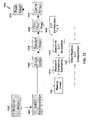
- a flowchartis shown of a method 1200 in which color mapping and exposure correction are integrated according to one embodiment of the present invention.
- the method 1200receives an image from a source such as a digital camera (step 1202 ) and performs JPEG decompression on the image (step 1204 ).
- the method 1200reduces the image using the techniques described above with respect to FIGS. 1B and 2B (step 102 ).
- the method 1200then performs automatic color balancing and automatic exposure correction on the image using an integrated process.
- Color balancingfor example, is often performed in the RGB space using three one-dimensional lookup tables.
- lookup tablesmay be combined with the exposure correction lookup tables described above to generate three one-dimensional lookup tables that perform both color balancing and exposure correction with a single set of one-dimensional lookups.
- exposure correction estimationmay be performed (step 1218 ) using the techniques disclosed herein to generate three one-dimensional exposure correction lookup tables (step 1219 ).
- Three one-dimensional color-balancing lookup tablesmay also be computed (step 1220 ) and combined with the exposure correction lookup tables generated in step 1219 (step 1222 ).
- the method 1200may perform any of a variety of image processing steps on the decompressed image, such as rotating the image (step 1206 ) and sharpening the image (step 1208 ). These particular image processing steps are shown merely for purposes of example and do not constitute limitations of the present invention.
- the method 1200performs color mapping on the image (step 1210 ).
- Color mappingoften involves several operations, including a one-dimensional pre-lookup table, a three-dimensional matrix or three-dimensional lookup, and a one-dimensional post-lookup table.
- Exposure correctionmay be integrated into the one-dimensional pre-lookup table operation of color mapping using the single set of three one-dimensional lookup tables (generated in step 1222 ) that perform the combined function of exposure correction, color balance, and the one-dimensional pre-lookup table portion of color mapping.
- the methodprepares the image for printing (or other output) by upsizing the image (step 1214 ).
- the method 1200then prints the image (step 1216 ). It should be appreciated that various steps in the method 1200 (such as steps 1204 , 1206 , 1208 , 1214 , and 1216 ) are provided merely as examples of steps that may be performed in conjunction with processing of the input image 202 and do not constitute limitations of the present invention.
- One advantage of the techniques disclosed hereinis that they may operate in the RGB space, thereby making them susceptible to being integrated with color mapping as just described. Integrating exposure correction with color mapping reduces the number of steps that are required to optimize an image for printing and may therefore make it possible to perform such processing more quickly than other methods which correct image exposure in a luminance-chrominance space or other non-linear space.
- the techniques described abovemay be implemented, for example, in hardware, software, firmware, or any combination thereof.
- the techniques described abovemay be implemented in one or more computer programs executing on a programmable computer including a processor, a storage medium readable by the processor (including, for example, volatile and non-volatile memory and/or storage elements), at least one input device, and at least one output device.
- Program codemay be applied to input entered using the input device to perform the functions described and to generate output.
- the outputmay be provided to one or more output devices.
- Each computer program within the scope of the claims belowmay be implemented in any programming language, such as assembly language, machine language, a high-level procedural programming language, or an object-oriented programming language.
- the programming languagemay, for example, be a compiled or interpreted programming language.
- Each such computer programmay be implemented in a computer program product tangibly embodied in a machine-readable storage device for execution by a computer processor.
- Method steps of the inventionmay be performed by a computer processor executing a program tangibly embodied on a computer-readable medium to perform functions of the invention by operating on input and generating output.
- Suitable processorsinclude, by way of example, both general and special purpose microprocessors.
- the processorreceives instructions and data from a read-only memory and/or a random access memory.
- Storage devices suitable for tangibly embodying computer program instructionsinclude, for example, all forms of non-volatile memory, such as semiconductor memory devices, including EPROM, EEPROM, and flash memory devices; magnetic disks such as internal hard disks and removable disks; magneto-optical disks; and CD-ROMs. Any of the foregoing may be supplemented by, or incorporated in, specially-designed ASICs (application-specific integrated circuits).
- a computercan generally also receive programs and data from a storage medium such as an internal disk (not shown) or a removable disk.
Landscapes
- Engineering & Computer Science (AREA)
- Multimedia (AREA)
- Signal Processing (AREA)
- Image Processing (AREA)
- Facsimile Image Signal Circuits (AREA)
Abstract
Description
T(i)=(A+Btanh(−s(i+o)))1/γ,
the step (A) may transform gray level g in the source image by applying the function T−1(g) to the gray level to produce transformed intensities, and the step (B) may include a step of adding an exposure offset Δe to the transformed intensities to produce corrected transformed intensities.
L=255(LL)1/γ.
- (1) the average activity within the ROT242 (defined as the ratio of the number of active pixels in the ROT to the total number of pixels in the ROI) is above a specified minimum activity threshold AMIN; and
- (2) the absolute logarithm of the ratio of the average linear luminance within the ROI to the average linear luminance of the remaining image (i.e., the portion of the linearized
luminance channel 224 not including the ROI242) is the highest in the thumbnail image222.
- (2) the absolute logarithm of the ratio of the average linear luminance within the ROI to the average linear luminance of the remaining image (i.e., the portion of the linearized
H(•)=(1−p(ROI))HI(•)+p(ROI)HROI(•) Equation 2
where f is the feature value vector208 and x is the
x=(FTF)−1FTe. Equation 4
x=(FTWF)−1FTWe. Equation 5
T(i)=(A+Btanh(−s(i+o)))1/γ, Equation 6
where A, B, s and o are parameters of the S-shaped tone reproduction curve and γ is the monitor gamma. It should be appreciated that the parameters s and o in Equation 6 are not the same as the parameters s and o in
g′=T(T−1(g)+Δe), Equation 7
where g′ is the exposure-corrected gray level in RGB space. The
Claims (11)
T(i)=(A+Btanh(−s(+o)))1/γ
T(i)=(A+Btanh(−s(i+o)))1/γ
T(i)=(A+Btanh(−s(i+o)))l/γ
Priority Applications (7)
| Application Number | Priority Date | Filing Date | Title |
|---|---|---|---|
| US10/375,440US7283666B2 (en) | 2003-02-27 | 2003-02-27 | Digital image exposure correction |
| PCT/US2004/004964WO2004077816A2 (en) | 2003-02-27 | 2004-02-19 | Digital image exposure correction |
| EP04712899AEP1597911A2 (en) | 2003-02-27 | 2004-02-19 | Digital image exposure correction |
| JP2005518583AJP2006515136A (en) | 2003-02-27 | 2004-02-19 | Digital image exposure compensation |
| US11/546,633US7826660B2 (en) | 2003-02-27 | 2006-10-12 | Digital image exposure correction |
| JP2008213280AJP2009005395A (en) | 2003-02-27 | 2008-08-21 | Correction of digital image exposure |
| US12/874,809US8265420B2 (en) | 2003-02-27 | 2010-09-02 | Digital image exposure correction |
Applications Claiming Priority (1)
| Application Number | Priority Date | Filing Date | Title |
|---|---|---|---|
| US10/375,440US7283666B2 (en) | 2003-02-27 | 2003-02-27 | Digital image exposure correction |
Related Child Applications (1)
| Application Number | Title | Priority Date | Filing Date |
|---|---|---|---|
| US11/546,633DivisionUS7826660B2 (en) | 2003-02-27 | 2006-10-12 | Digital image exposure correction |
Publications (2)
| Publication Number | Publication Date |
|---|---|
| US20040170316A1 US20040170316A1 (en) | 2004-09-02 |
| US7283666B2true US7283666B2 (en) | 2007-10-16 |
Family
ID=32907818
Family Applications (3)
| Application Number | Title | Priority Date | Filing Date |
|---|---|---|---|
| US10/375,440Expired - LifetimeUS7283666B2 (en) | 2003-02-27 | 2003-02-27 | Digital image exposure correction |
| US11/546,633Expired - LifetimeUS7826660B2 (en) | 2003-02-27 | 2006-10-12 | Digital image exposure correction |
| US12/874,809Expired - Fee RelatedUS8265420B2 (en) | 2003-02-27 | 2010-09-02 | Digital image exposure correction |
Family Applications After (2)
| Application Number | Title | Priority Date | Filing Date |
|---|---|---|---|
| US11/546,633Expired - LifetimeUS7826660B2 (en) | 2003-02-27 | 2006-10-12 | Digital image exposure correction |
| US12/874,809Expired - Fee RelatedUS8265420B2 (en) | 2003-02-27 | 2010-09-02 | Digital image exposure correction |
Country Status (4)
| Country | Link |
|---|---|
| US (3) | US7283666B2 (en) |
| EP (1) | EP1597911A2 (en) |
| JP (2) | JP2006515136A (en) |
| WO (1) | WO2004077816A2 (en) |
Cited By (6)
| Publication number | Priority date | Publication date | Assignee | Title |
|---|---|---|---|---|
| US20080075383A1 (en)* | 2006-09-22 | 2008-03-27 | Peng Wu | Methods And Systems For Identifying An Ill-Exposed Image |
| US7826660B2 (en) | 2003-02-27 | 2010-11-02 | Saquib Suhail S | Digital image exposure correction |
| US7907157B2 (en) | 2002-02-19 | 2011-03-15 | Senshin Capital, Llc | Technique for printing a color image |
| USRE42473E1 (en) | 2001-05-30 | 2011-06-21 | Senshin Capital, Llc | Rendering images utilizing adaptive error diffusion |
| USRE43149E1 (en) | 2001-03-27 | 2012-01-31 | Senshin Capital, Llc | Method for generating a halftone of a source image |
| US8773685B2 (en) | 2003-07-01 | 2014-07-08 | Intellectual Ventures I Llc | High-speed digital image printing system |
Families Citing this family (59)
| Publication number | Priority date | Publication date | Assignee | Title |
|---|---|---|---|---|
| CA2448327A1 (en)* | 2001-05-30 | 2002-12-05 | Polaroid Corporation | A high speed photo-printing apparatus |
| US6842186B2 (en)* | 2001-05-30 | 2005-01-11 | Polaroid Corporation | High speed photo-printing apparatus |
| US6950211B2 (en)* | 2001-07-05 | 2005-09-27 | Corel Corporation | Fine moire correction in images |
| US20040181757A1 (en)* | 2003-03-12 | 2004-09-16 | Brady Deborah A. | Convenient accuracy analysis of content analysis engine |
| JP4341295B2 (en)* | 2003-05-16 | 2009-10-07 | セイコーエプソン株式会社 | Judging backlit human images |
| US7375854B2 (en)* | 2004-03-12 | 2008-05-20 | Vastview Technology, Inc. | Method for color correction |
| US8004511B2 (en) | 2004-12-02 | 2011-08-23 | Sharp Laboratories Of America, Inc. | Systems and methods for distortion-related source light management |
| US7982707B2 (en) | 2004-12-02 | 2011-07-19 | Sharp Laboratories Of America, Inc. | Methods and systems for generating and applying image tone scale adjustments |
| US7782405B2 (en) | 2004-12-02 | 2010-08-24 | Sharp Laboratories Of America, Inc. | Systems and methods for selecting a display source light illumination level |
| US7961199B2 (en)* | 2004-12-02 | 2011-06-14 | Sharp Laboratories Of America, Inc. | Methods and systems for image-specific tone scale adjustment and light-source control |
| US8111265B2 (en) | 2004-12-02 | 2012-02-07 | Sharp Laboratories Of America, Inc. | Systems and methods for brightness preservation using a smoothed gain image |
| US8913089B2 (en) | 2005-06-15 | 2014-12-16 | Sharp Laboratories Of America, Inc. | Methods and systems for enhancing display characteristics with frequency-specific gain |
| US8922594B2 (en) | 2005-06-15 | 2014-12-30 | Sharp Laboratories Of America, Inc. | Methods and systems for enhancing display characteristics with high frequency contrast enhancement |
| US7924261B2 (en) | 2004-12-02 | 2011-04-12 | Sharp Laboratories Of America, Inc. | Methods and systems for determining a display light source adjustment |
| US7768496B2 (en) | 2004-12-02 | 2010-08-03 | Sharp Laboratories Of America, Inc. | Methods and systems for image tonescale adjustment to compensate for a reduced source light power level |
| US7800577B2 (en) | 2004-12-02 | 2010-09-21 | Sharp Laboratories Of America, Inc. | Methods and systems for enhancing display characteristics |
| US8120570B2 (en) | 2004-12-02 | 2012-02-21 | Sharp Laboratories Of America, Inc. | Systems and methods for tone curve generation, selection and application |
| US8947465B2 (en) | 2004-12-02 | 2015-02-03 | Sharp Laboratories Of America, Inc. | Methods and systems for display-mode-dependent brightness preservation |
| US7515160B2 (en)* | 2006-07-28 | 2009-04-07 | Sharp Laboratories Of America, Inc. | Systems and methods for color preservation with image tone scale corrections |
| US9083969B2 (en)* | 2005-08-12 | 2015-07-14 | Sharp Laboratories Of America, Inc. | Methods and systems for independent view adjustment in multiple-view displays |
| US7839406B2 (en) | 2006-03-08 | 2010-11-23 | Sharp Laboratories Of America, Inc. | Methods and systems for enhancing display characteristics with ambient illumination input |
| JP5196731B2 (en)* | 2006-04-20 | 2013-05-15 | キヤノン株式会社 | Image processing apparatus and image processing method |
| US8160364B2 (en)* | 2007-02-16 | 2012-04-17 | Raytheon Company | System and method for image registration based on variable region of interest |
| US7826681B2 (en) | 2007-02-28 | 2010-11-02 | Sharp Laboratories Of America, Inc. | Methods and systems for surround-specific display modeling |
| KR101341095B1 (en)* | 2007-08-23 | 2013-12-13 | 삼성전기주식회사 | Apparatus and method for capturing images having optimized quality under night scene conditions |
| US8155434B2 (en) | 2007-10-30 | 2012-04-10 | Sharp Laboratories Of America, Inc. | Methods and systems for image enhancement |
| US8345038B2 (en) | 2007-10-30 | 2013-01-01 | Sharp Laboratories Of America, Inc. | Methods and systems for backlight modulation and brightness preservation |
| US8378956B2 (en) | 2007-11-30 | 2013-02-19 | Sharp Laboratories Of America, Inc. | Methods and systems for weighted-error-vector-based source light selection |
| US9177509B2 (en) | 2007-11-30 | 2015-11-03 | Sharp Laboratories Of America, Inc. | Methods and systems for backlight modulation with scene-cut detection |
| US8207932B2 (en) | 2007-12-26 | 2012-06-26 | Sharp Laboratories Of America, Inc. | Methods and systems for display source light illumination level selection |
| US8179363B2 (en) | 2007-12-26 | 2012-05-15 | Sharp Laboratories Of America, Inc. | Methods and systems for display source light management with histogram manipulation |
| US8223113B2 (en) | 2007-12-26 | 2012-07-17 | Sharp Laboratories Of America, Inc. | Methods and systems for display source light management with variable delay |
| US8203579B2 (en) | 2007-12-26 | 2012-06-19 | Sharp Laboratories Of America, Inc. | Methods and systems for backlight modulation with image characteristic mapping |
| US8169431B2 (en) | 2007-12-26 | 2012-05-01 | Sharp Laboratories Of America, Inc. | Methods and systems for image tonescale design |
| US8531379B2 (en) | 2008-04-28 | 2013-09-10 | Sharp Laboratories Of America, Inc. | Methods and systems for image compensation for ambient conditions |
| US8416179B2 (en) | 2008-07-10 | 2013-04-09 | Sharp Laboratories Of America, Inc. | Methods and systems for color preservation with a color-modulated backlight |
| US8208762B1 (en)* | 2008-08-12 | 2012-06-26 | Adobe Systems Incorporated | Optimizing the performance of an image editing system in a client-server environment |
| US9330630B2 (en) | 2008-08-30 | 2016-05-03 | Sharp Laboratories Of America, Inc. | Methods and systems for display source light management with rate change control |
| TWI464706B (en)* | 2009-03-13 | 2014-12-11 | Micro Star Int Co Ltd | Dark portion exposure compensation method for simulating high dynamic range with single image and image processing device using the same |
| JP5295854B2 (en)* | 2009-04-28 | 2013-09-18 | 株式会社レグラス | Image processing apparatus and image processing program |
| US8165724B2 (en) | 2009-06-17 | 2012-04-24 | Sharp Laboratories Of America, Inc. | Methods and systems for power-controlling display devices |
| TWI407777B (en)* | 2009-07-20 | 2013-09-01 | Silicon Integrated Sys Corp | Apparatus and method for feature-based dynamic contrast enhancement |
| US20110205397A1 (en)* | 2010-02-24 | 2011-08-25 | John Christopher Hahn | Portable imaging device having display with improved visibility under adverse conditions |
| JP5744510B2 (en)* | 2010-12-28 | 2015-07-08 | キヤノン株式会社 | Image processing method |
| CN102625030B (en)* | 2011-02-01 | 2014-10-01 | 株式会社理光 | video enhancement method and system |
| US8644638B2 (en)* | 2011-02-25 | 2014-02-04 | Microsoft Corporation | Automatic localized adjustment of image shadows and highlights |
| US9111174B2 (en)* | 2012-02-24 | 2015-08-18 | Riverain Technologies, LLC | Machine learnng techniques for pectoral muscle equalization and segmentation in digital mammograms |
| FR3002824A1 (en)* | 2013-03-04 | 2014-09-05 | St Microelectronics Grenoble 2 | METHOD AND DEVICE FOR GENERATING IMAGES WITH A HIGH DYNAMIC RANGE |
| CN104298982B (en)* | 2013-07-16 | 2019-03-08 | 深圳市腾讯计算机系统有限公司 | A kind of character recognition method and device |
| WO2015133712A1 (en)* | 2014-03-06 | 2015-09-11 | 삼성전자 주식회사 | Image decoding method and device therefor, and image encoding method and device therefor |
| GB2520822B (en)* | 2014-10-10 | 2016-01-13 | Aveva Solutions Ltd | Image rendering of laser scan data |
| US9911061B2 (en)* | 2015-06-07 | 2018-03-06 | Apple Inc. | Fast histogram-based object tracking |
| CN105006019B (en)* | 2015-07-13 | 2017-11-28 | 山东易创电子有限公司 | A kind of sequence chart exposure method of adjustment and device |
| US10152935B2 (en)* | 2016-02-29 | 2018-12-11 | Mitsubishi Electric Corporation | Color correction apparatus, display apparatus, and color correction method |
| CN107220953A (en) | 2017-06-16 | 2017-09-29 | 广东欧珀移动通信有限公司 | image processing method, device and terminal |
| CN107291473B (en)* | 2017-06-22 | 2020-12-08 | 深圳传音通讯有限公司 | Wallpaper setting method and device |
| US10628929B2 (en)* | 2018-05-28 | 2020-04-21 | Augentix Inc. | Method and computer system of image enhancement |
| CN109447915B (en)* | 2018-10-29 | 2021-06-29 | 北京康拓红外技术股份有限公司 | Line scanning image quality improving method based on characteristic model establishment and gamma gray correction |
| JP6757392B2 (en) | 2018-11-21 | 2020-09-16 | 株式会社モルフォ | Image generator, image generation method and image generation program |
Citations (34)
| Publication number | Priority date | Publication date | Assignee | Title |
|---|---|---|---|---|
| US4154523A (en) | 1977-05-31 | 1979-05-15 | Eastman Kodak Company | Exposure determination apparatus for a photographic printer |
| US4168120A (en) | 1978-04-17 | 1979-09-18 | Pako Corporation | Automatic exposure corrections for photographic printer |
| US4933709A (en) | 1989-09-25 | 1990-06-12 | Eastman Kodak Company | Adjusting photographic printer color exposure determination algorithms |
| US4962403A (en) | 1989-12-11 | 1990-10-09 | Eastman Kodak Company | Adjusting photographic printer color exposure determination algorithms |
| JPH04119338A (en) | 1990-09-10 | 1992-04-20 | Nikon Corp | Camera photometry calculation device |
| JPH06308632A (en) | 1993-04-26 | 1994-11-04 | Fuji Photo Film Co Ltd | Exposure control method |
| EP0762736A2 (en) | 1995-08-30 | 1997-03-12 | Hewlett-Packard Company | Automatic color processing to correct hue shift and incorrect exposure |
| EP0773470A1 (en) | 1995-11-09 | 1997-05-14 | Fuji Photo Film Co., Ltd. | Image processing method for photographic printer |
| JPH09138465A (en) | 1995-10-27 | 1997-05-27 | Samsung Aerospace Ind Ltd | Photo printing equipment |
| US5724456A (en) | 1995-03-31 | 1998-03-03 | Polaroid Corporation | Brightness adjustment of images using digital scene analysis |
| US5809164A (en) | 1996-03-07 | 1998-09-15 | Polaroid Corporation | System and method for color gamut and tone compression using an ideal mapping function |
| US5818975A (en) | 1996-10-28 | 1998-10-06 | Eastman Kodak Company | Method and apparatus for area selective exposure adjustment |
| US5835244A (en)* | 1993-10-15 | 1998-11-10 | Linotype-Hell Ag | Method and apparatus for the conversion of color values |
| US5978106A (en) | 1996-06-21 | 1999-11-02 | Nikon Corporation | Picture image processing method |
| WO2000004492A2 (en) | 1998-07-15 | 2000-01-27 | Imation Corp. | Imaging system and method |
| JP2000050077A (en) | 1998-05-28 | 2000-02-18 | Eastman Kodak Co | Digital photograph finishing system containing digital picture processing of selective acquisition color photograph medium |
| JP2000050080A (en) | 1998-05-28 | 2000-02-18 | Eastman Kodak Co | Digital photograph finishing system containing digital picture processing of film exposure lacking gamma, scene balance, contrast normalization and picture visualization |
| US6028957A (en)* | 1996-03-07 | 2000-02-22 | Minolta Co., Ltd. | Image forming apparatus having a noise removing unit |
| JP2000184270A (en) | 1998-12-14 | 2000-06-30 | Ricoh Co Ltd | Digital still video camera |
| US6128415A (en) | 1996-09-06 | 2000-10-03 | Polaroid Corporation | Device profiles for use in a digital image processing system |
| US6133983A (en) | 1993-11-12 | 2000-10-17 | Eastman Kodak Company | Photographic printing method and apparatus for setting a degree of illuminant chromatic correction using inferential illuminant detection |
| EP1056272A1 (en) | 1999-05-20 | 2000-11-29 | Eastman Kodak Company | Correcting exposure in a rendered digital image |
| US6204940B1 (en) | 1998-05-15 | 2001-03-20 | Hewlett-Packard Company | Digital processing of scanned negative films |
| KR20010037684A (en) | 1999-10-19 | 2001-05-15 | 이중구 | Apparatus for correlating of exposure automatically of a digital still camera and method for performing the same |
| US6243133B1 (en)* | 1997-03-07 | 2001-06-05 | Eastman Kodak Company | Method for automatic scene balance of digital images |
| JP2001160908A (en) | 1999-12-02 | 2001-06-12 | Noritsu Koki Co Ltd | Color density correction method, recording medium storing color density correction program, image processing device, and photographic printing device |
| US6263091B1 (en) | 1997-08-22 | 2001-07-17 | International Business Machines Corporation | System and method for identifying foreground and background portions of digitized images |
| US6282317B1 (en) | 1998-12-31 | 2001-08-28 | Eastman Kodak Company | Method for automatic determination of main subjects in photographic images |
| JP2003008986A (en) | 2001-06-27 | 2003-01-10 | Casio Comput Co Ltd | Imaging device and exposure control method |
| US6563945B2 (en)* | 1997-03-24 | 2003-05-13 | Jack M. Holm | Pictorial digital image processing incorporating image and output device modifications |
| US6608926B1 (en)* | 1998-06-24 | 2003-08-19 | Canon Kabushiki Kaisha | Image processing method, image processing apparatus and recording medium |
| US6628826B1 (en)* | 1999-11-29 | 2003-09-30 | Eastman Kodak Company | Color reproduction of images from color films |
| US6650771B1 (en)* | 1999-11-22 | 2003-11-18 | Eastman Kodak Company | Color management system incorporating parameter control channels |
| US6956967B2 (en)* | 2002-05-20 | 2005-10-18 | Eastman Kodak Company | Color transformation for processing digital images |
Family Cites Families (185)
| Publication number | Priority date | Publication date | Assignee | Title |
|---|---|---|---|---|
| US3820133A (en) | 1972-07-24 | 1974-06-25 | C Adorney | Teaching device |
| US3864708A (en) | 1973-12-04 | 1975-02-04 | Brian S Allen | Automatic photographic apparatus and postcard vending machine |
| US4070587A (en) | 1975-02-14 | 1978-01-24 | Canon Kabushiki Kaisha | Energizing control system for an intermittently energized device |
| US4072973A (en) | 1976-01-26 | 1978-02-07 | Mayo William D | Camera signal system for portrait taking |
| US4089017A (en) | 1976-09-07 | 1978-05-09 | Polaroid Corporation | Automatic photostudio |
| JPH10285390A (en) | 1997-04-03 | 1998-10-23 | Minolta Co Ltd | Image processor |
| JPS5590383A (en) | 1978-12-27 | 1980-07-08 | Canon Inc | Thermal printer |
| US4284876A (en) | 1979-04-24 | 1981-08-18 | Oki Electric Industry Co., Ltd. | Thermal printing system |
| US4347518A (en) | 1979-09-04 | 1982-08-31 | Gould Inc. | Thermal array protection apparatus |
| JPS6036397B2 (en) | 1980-03-31 | 1985-08-20 | 株式会社東芝 | thermal recording device |
| JPS574784A (en) | 1980-06-13 | 1982-01-11 | Canon Inc | Thermal printer |
| US4385302A (en) | 1980-10-16 | 1983-05-24 | Fuji Xerox Co., Ltd. | Multicolor recording apparatus |
| JPS57138960A (en) | 1981-02-20 | 1982-08-27 | Fuji Xerox Co Ltd | Multicolor heat sensitive recorder |
| DE3273429D1 (en) | 1981-06-19 | 1986-10-30 | Toshiba Kk | Thermal printer |
| US4391535A (en) | 1981-08-10 | 1983-07-05 | Intermec Corporation | Method and apparatus for controlling the area of a thermal print medium that is exposed by a thermal printer |
| JPS58150370A (en) | 1982-03-02 | 1983-09-07 | Sony Corp | Producing system of gradation signal for printer |
| US4514738A (en) | 1982-11-22 | 1985-04-30 | Tokyo Shibaura Denki Kabushiki Kaisha | Thermal recording system |
| JPS59127781A (en) | 1983-01-11 | 1984-07-23 | Fuji Xerox Co Ltd | Driving circuit for thermal head |
| JPS59182758A (en) | 1983-04-01 | 1984-10-17 | Fuji Xerox Co Ltd | Drive circuit for thermal head |
| US4540992A (en) | 1983-04-07 | 1985-09-10 | Kabushiki Kaisha Daini Seikosha | Thermal color transfer system |
| US4688051A (en) | 1983-08-15 | 1987-08-18 | Ricoh Company, Ltd. | Thermal print head driving system |
| JPS6085675A (en) | 1983-10-17 | 1985-05-15 | Fuji Xerox Co Ltd | Color copying machine |
| JPS60101051A (en) | 1983-11-09 | 1985-06-05 | Fuji Xerox Co Ltd | Multicolor recording system |
| US4563691A (en) | 1984-12-24 | 1986-01-07 | Fuji Xerox Co., Ltd. | Thermo-sensitive recording apparatus |
| US4884080A (en) | 1985-01-31 | 1989-11-28 | Kabushiki Kaisha Toshiba | Color image printing apparatus |
| US5208686A (en) | 1985-03-01 | 1993-05-04 | Manchester R&D Partnership | Liquid crystal color display and method |
| DE3688715D1 (en) | 1985-03-30 | 1993-08-26 | Hitachi Ltd | PRINTING METHOD OF THE SCANING TYPE AND ITS REALIZATION DEVICE. |
| US4686549A (en) | 1985-12-16 | 1987-08-11 | Minnesota Mining And Manufacturing Company | Receptor sheet for thermal mass transfer printing |
| JPS62275768A (en) | 1986-05-24 | 1987-11-30 | Sony Corp | Printer |
| US4738526A (en) | 1986-11-21 | 1988-04-19 | Autostudio Corporation | Auto-portrait photo studio |
| JPS63202182A (en) | 1987-02-18 | 1988-08-22 | Olympus Optical Co Ltd | Tilted dot pattern forming method |
| US4739344A (en) | 1987-02-27 | 1988-04-19 | Astro-Med, Inc. | Chart recorded having multiple thermal print heads |
| JPH02139258A (en) | 1988-08-18 | 1990-05-29 | Ricoh Co Ltd | Recording density correction device |
| US5086484A (en) | 1988-08-24 | 1992-02-04 | Canon Kabushiki Kaisha | Image processing apparatus with fixed or variable threshold |
| DE68927970T2 (en) | 1988-09-08 | 1997-10-09 | Canon Kk | Point image data output device |
| JPH02121853A (en) | 1988-10-31 | 1990-05-09 | Toshiba Corp | Thermal head control circuit |
| JP2984009B2 (en) | 1989-02-03 | 1999-11-29 | 株式会社リコー | Thermal head drive |
| JPH0813552B2 (en) | 1989-02-17 | 1996-02-14 | 松下電器産業株式会社 | Gradation printer |
| JPH02235655A (en) | 1989-03-09 | 1990-09-18 | Kyocera Corp | Thermal head drive device |
| US4907014A (en)* | 1989-05-18 | 1990-03-06 | Calcomp Inc. | Safely retracting paper-cutting apparatus for a roll paper printer |
| US5086306A (en) | 1989-07-19 | 1992-02-04 | Ricoh Company, Ltd. | Line head driving apparatus |
| JP2523188B2 (en) | 1989-08-07 | 1996-08-07 | シャープ株式会社 | Printing control method of thermal printer |
| US5045952A (en) | 1989-08-21 | 1991-09-03 | Xerox Corporation | Method for edge enhanced error diffusion |
| JP2612616B2 (en) | 1989-08-31 | 1997-05-21 | 富士写真フイルム株式会社 | Method and apparatus for driving thermal head in printer |
| US5285220A (en) | 1989-11-22 | 1994-02-08 | Canon Kabushiki Kaisha | Image recording apparatus with tone correction for individual recording heads |
| US5046118A (en)* | 1990-02-06 | 1991-09-03 | Eastman Kodak Company | Tone-scale generation method and apparatus for digital x-ray images |
| WO1991015831A1 (en) | 1990-04-05 | 1991-10-17 | Seiko Epson Corporation | Page description language interpreter |
| US5130821A (en) | 1990-04-16 | 1992-07-14 | Eastman Kodak Company | Method and apparatus for digital halftoning employing density distribution for selection of a threshold template |
| US5208684A (en) | 1990-04-26 | 1993-05-04 | Fujitsu Limited | Half-tone image processing system |
| US5323245A (en) | 1990-09-14 | 1994-06-21 | Minnesota Mining And Manufacturing Company | Perpendicular, unequal frequency non-conventional screen patterns for electronic halftone generation |
| US5268706A (en) | 1991-02-14 | 1993-12-07 | Alps Electric Co., Ltd. | Actuating control method of thermal head |
| JP2957721B2 (en) | 1991-02-25 | 1999-10-06 | アルプス電気株式会社 | Thermal control method of thermal head |
| US5132703A (en) | 1991-03-08 | 1992-07-21 | Yokogawa Electric Corporation | Thermal history control in a recorder using a line thermal head |
| US5132709A (en) | 1991-08-26 | 1992-07-21 | Zebra Technologies Corporation | Apparatus and method for closed-loop, thermal control of printing head |
| US5307425A (en) | 1991-09-02 | 1994-04-26 | Rohm Co., Ltd. | Bi-level halftone processing circuit and image processing apparatus using the same |
| US5455685A (en)* | 1991-09-04 | 1995-10-03 | Fuji Photo Film Co., Ltd. | Video camera exposure control apparatus for controlling iris diaphragm and automatic gain control operating speed |
| US5244861A (en) | 1992-01-17 | 1993-09-14 | Eastman Kodak Company | Receiving element for use in thermal dye transfer |
| US5625399A (en) | 1992-01-31 | 1997-04-29 | Intermec Corporation | Method and apparatus for controlling a thermal printhead |
| US5777599A (en) | 1992-02-14 | 1998-07-07 | Oki Electric Industry Co., Ltd. | Image generation device and method using dithering |
| JPH0654195A (en) | 1992-02-28 | 1994-02-25 | Eastman Kodak Co | System and method for image scanner for improvement of microfilm image quality |
| JPH07205469A (en) | 1992-03-27 | 1995-08-08 | Nec Data Terminal Ltd | Thermal head |
| JP3412174B2 (en)* | 1992-05-21 | 2003-06-03 | 松下電器産業株式会社 | Automatic exposure control device |
| JP3209797B2 (en) | 1992-07-03 | 2001-09-17 | 松下電器産業株式会社 | Gradation printer |
| JP2850930B2 (en) | 1992-10-12 | 1999-01-27 | 日本ビクター株式会社 | Melt type thermal transfer printing system |
| US5729274A (en) | 1992-11-05 | 1998-03-17 | Fuji Photo Film Co., Ltd. | Color direct thermal printing method and thermal head of thermal printer |
| US5469203A (en) | 1992-11-24 | 1995-11-21 | Eastman Kodak Company | Parasitic resistance compensation for a thermal print head |
| US5644351A (en) | 1992-12-04 | 1997-07-01 | Matsushita Electric Industrial Co., Ltd. | Thermal gradation printing apparatus |
| US5450099A (en) | 1993-04-08 | 1995-09-12 | Eastman Kodak Company | Thermal line printer with staggered head segments and overlap compensation |
| KR0138362B1 (en) | 1993-05-17 | 1998-05-15 | 김광호 | Thermal transfer printer device and method |
| US5805780A (en) | 1993-05-25 | 1998-09-08 | Dai Nippon Printing Co., Ltd. | Photographing box |
| JP3397371B2 (en) | 1993-05-27 | 2003-04-14 | キヤノン株式会社 | Recording device and recording method |
| US5818474A (en) | 1993-06-30 | 1998-10-06 | Canon Kabushiki Kaisha | Ink-jet recording apparatus and method using asynchronous masks |
| US5479263A (en) | 1993-07-01 | 1995-12-26 | Xerox Corporation | Gray pixel halftone encoder |
| US5623297A (en) | 1993-07-07 | 1997-04-22 | Intermec Corporation | Method and apparatus for controlling a thermal printhead |
| US5956067A (en) | 1993-10-28 | 1999-09-21 | Nisca Corporation | Thermal transfer printing device and method |
| JP2746088B2 (en) | 1993-11-30 | 1998-04-28 | 進工業株式会社 | Thermal head device |
| JP3066237B2 (en) | 1993-12-21 | 2000-07-17 | フジコピアン株式会社 | Thermal transfer material and color image forming method |
| JPH07178948A (en) | 1993-12-24 | 1995-07-18 | Shinko Electric Co Ltd | Thermal printer |
| DE69433608T2 (en) | 1993-12-27 | 2005-02-17 | Sharp K.K. | Grading control method and image quality improvement for a thermal printer |
| BE1008076A3 (en)* | 1994-02-15 | 1996-01-09 | Agfa Gevaert Nv | COLOR NEGATIVE SCANNING AND TRANSFORMATION IN COLORS OF ORIGINAL scene. |
| US5497174A (en) | 1994-03-11 | 1996-03-05 | Xerox Corporation | Voltage drop correction for ink jet printer |
| US5786900A (en) | 1994-03-23 | 1998-07-28 | Fuji Photo Film Co., Ltd. | Image recording device for recording multicolor images with dot pitch pattern randomly arranged only in the sub-scanning direction |
| JP3381755B2 (en) | 1994-10-11 | 2003-03-04 | セイコーエプソン株式会社 | Method and apparatus for improved adaptive filtering and thresholding to reduce image graininess |
| US5602653A (en) | 1994-11-08 | 1997-02-11 | Xerox Corporation | Pixel pair grid halftoning for a hyperacuity printer |
| US5786837A (en) | 1994-11-29 | 1998-07-28 | Agfa-Gevaert N.V. | Method and apparatus for thermal printing with voltage-drop compensation |
| JP2702426B2 (en) | 1994-12-16 | 1998-01-21 | 日本電気データ機器株式会社 | Thermal head device |
| JPH08169132A (en) | 1994-12-20 | 1996-07-02 | Nec Data Terminal Ltd | Thermal head device |
| US5694484A (en) | 1995-05-15 | 1997-12-02 | Polaroid Corporation | System and method for automatically processing image data to provide images of optimal perceptual quality |
| US5835627A (en) | 1995-05-15 | 1998-11-10 | Higgins; Eric W. | System and method for automatically optimizing image quality and processing time |
| US6128099A (en) | 1995-06-08 | 2000-10-03 | Delabastita; Paul A. | Halftone screen generator, halftone screen and method for generating same |
| US5707082A (en) | 1995-07-18 | 1998-01-13 | Moore Business Forms Inc | Thermally imaged colored baggage tags |
| US6657741B1 (en) | 1995-08-07 | 2003-12-02 | Tr Systems, Inc. | Multiple print engine system with selectively distributed ripped pages |
| JPH0952382A (en) | 1995-08-17 | 1997-02-25 | Fuji Photo Film Co Ltd | Method and apparatus for correcting heat accumulation |
| US5664253A (en) | 1995-09-12 | 1997-09-02 | Eastman Kodak Company | Stand alone photofinishing apparatus |
| JP3501567B2 (en) | 1995-09-28 | 2004-03-02 | 富士写真フイルム株式会社 | Color thermal printer |
| JP3523724B2 (en) | 1995-09-29 | 2004-04-26 | 東芝テック株式会社 | Thermal transfer color printer |
| JP4036896B2 (en)* | 1995-12-01 | 2008-01-23 | キネティック リミテッド | Imaging system |
| US5623581A (en) | 1996-01-22 | 1997-04-22 | Apbi Interactive Kiosk Systems | Direct view interactive photo kiosk and image forming process for same |
| US5913019A (en) | 1996-01-22 | 1999-06-15 | Foto Fantasy, Inc. | Direct view interactive photo kiosk and composite image forming process for same |
| JP3625333B2 (en) | 1996-02-13 | 2005-03-02 | 富士写真フイルム株式会社 | Thermal image recording apparatus and recording method |
| US5777638A (en) | 1996-02-22 | 1998-07-07 | Hewlett-Packard Company | Print mode to compensate for microbanding |
| US5956421A (en) | 1996-02-28 | 1999-09-21 | Canon Kabushiki Kaisha | Image processing method and apparatus for determining a binarization threshold value used for binarizing a multi-valued image and performing binarization processing |
| US5870505A (en)* | 1996-03-14 | 1999-02-09 | Polaroid Corporation | Method and apparatus for pixel level luminance adjustment |
| JP3589783B2 (en) | 1996-04-11 | 2004-11-17 | 富士写真フイルム株式会社 | Thermal storage correction method and device |
| US5909244A (en)* | 1996-04-15 | 1999-06-01 | Massachusetts Institute Of Technology | Real time adaptive digital image processing for dynamic range remapping of imagery including low-light-level visible imagery |
| US5880777A (en)* | 1996-04-15 | 1999-03-09 | Massachusetts Institute Of Technology | Low-light-level imaging and image processing |
| JP3426851B2 (en) | 1996-04-30 | 2003-07-14 | 大日本スクリーン製造株式会社 | Dot forming method for multicolor printing |
| US5889546A (en) | 1996-06-04 | 1999-03-30 | Shinko Electric Co., Ltd. | Heat accumulation control device for line-type thermoelectric printer |
| US5809177A (en) | 1996-06-06 | 1998-09-15 | Xerox Corporation | Hybrid error diffusion pattern shifting reduction using programmable threshold perturbation |
| US5668638A (en) | 1996-06-27 | 1997-09-16 | Xerox Corporation | Error diffusion method with symmetric enhancement |
| US6233360B1 (en) | 1996-09-24 | 2001-05-15 | Xerox Corporation | Method and system for hybrid error diffusion processing of image information using adaptive white and black reference values |
| JPH10109436A (en) | 1996-10-04 | 1998-04-28 | Seiko Denshi Kiki Kk | Color image recording method, color image recording device, and color image recording controlling method |
| JP3907783B2 (en)* | 1996-12-12 | 2007-04-18 | 富士フイルム株式会社 | Color conversion method |
| JPH10239780A (en) | 1996-12-24 | 1998-09-11 | Fuji Photo Film Co Ltd | Method and device for outputting photographic image data |
| US5970224A (en) | 1997-04-14 | 1999-10-19 | Xerox Corporation | Multifunctional printing system with queue management |
| JPH1110852A (en) | 1997-06-24 | 1999-01-19 | Fuji Photo Film Co Ltd | Multihead type printer |
| US6771832B1 (en)* | 1997-07-29 | 2004-08-03 | Panasonic Communications Co., Ltd. | Image processor for processing an image with an error diffusion process and image processing method for processing an image with an error diffusion process |
| JP3683387B2 (en) | 1997-08-01 | 2005-08-17 | シャープ株式会社 | Network computer built-in printer and computer network system provided with the same |
| JPH1158807A (en) | 1997-08-11 | 1999-03-02 | Minolta Co Ltd | Recorder |
| JP3690082B2 (en) | 1997-09-11 | 2005-08-31 | コニカミノルタビジネステクノロジーズ株式会社 | Selection method of image forming apparatus connected to network |
| US6334660B1 (en) | 1998-10-31 | 2002-01-01 | Hewlett-Packard Company | Varying the operating energy applied to an inkjet print cartridge based upon the operating conditions |
| US6069982A (en) | 1997-12-23 | 2000-05-30 | Polaroid Corporation | Estimation of frequency dependence and grey-level dependence of noise in an image |
| US6101000A (en) | 1998-01-30 | 2000-08-08 | Eastman Kodak Company | Photographic processing apparatus and method |
| US6172768B1 (en)* | 1998-02-05 | 2001-01-09 | Canon Kabushiki Kaisha | Halftoning with changeable error diffusion weights |
| US6223267B1 (en) | 1998-02-26 | 2001-04-24 | Hewlett-Packard Company | Dynamically allocable RAM disk |
| US6106173A (en) | 1998-03-06 | 2000-08-22 | Asahi Kogaku Kogyo Kabushiki Kaisha | Image-forming system including a plurality of thermal heads and an image-forming sheet with a plurality of types of micro-capsules |
| US6226021B1 (en) | 1998-04-03 | 2001-05-01 | Alps Electric Co., Ltd. | Image forming method of thermal transfer printer |
| US6760489B1 (en)* | 1998-04-06 | 2004-07-06 | Seiko Epson Corporation | Apparatus and method for image data interpolation and medium on which image data interpolation program is recorded |
| US5995654A (en) | 1998-05-28 | 1999-11-30 | Eastman Kodak Company | Digital photofinishing system including scene balance and image sharpening digital image processing |
| US6631208B1 (en) | 1998-05-29 | 2003-10-07 | Fuji Photo Film Co., Ltd. | Image processing method |
| US6208429B1 (en) | 1998-05-29 | 2001-03-27 | Flashpoint Technology, Inc. | Method and system for band printing of rotated digital image data |
| JP3590265B2 (en) | 1998-06-11 | 2004-11-17 | 富士写真フイルム株式会社 | Image processing method |
| US6694051B1 (en)* | 1998-06-24 | 2004-02-17 | Canon Kabushiki Kaisha | Image processing method, image processing apparatus and recording medium |
| US6104468A (en) | 1998-06-29 | 2000-08-15 | Eastman Kodak Company | Image movement in a photographic laboratory |
| JP3556859B2 (en)* | 1998-09-08 | 2004-08-25 | 富士写真フイルム株式会社 | Image correction method, image correction device, and recording medium |
| JP3754849B2 (en) | 1998-10-30 | 2006-03-15 | キヤノン株式会社 | Data communication apparatus, control method, storage medium, and image printing system |
| US6847376B2 (en)* | 1998-11-13 | 2005-01-25 | Lightsurf Technologies, Inc. | Method and system for characterizing color display monitor output |
| JP3829508B2 (en) | 1998-11-27 | 2006-10-04 | セイコーエプソン株式会社 | Image processing apparatus, image processing method, and printing apparatus |
| JP3820497B2 (en)* | 1999-01-25 | 2006-09-13 | 富士写真フイルム株式会社 | Imaging apparatus and correction processing method for automatic exposure control |
| JP3369497B2 (en) | 1999-01-27 | 2003-01-20 | 松下電送システム株式会社 | Terminal device and MFP |
| US6332137B1 (en)* | 1999-02-11 | 2001-12-18 | Toshikazu Hori | Parallel associative learning memory for a standalone hardwired recognition system |
| US6276775B1 (en) | 1999-04-29 | 2001-08-21 | Hewlett-Packard Company | Variable drop mass inkjet drop generator |
| TW473696B (en) | 1999-06-29 | 2002-01-21 | Casio Computer Co Ltd | Printing apparatus and printing method |
| JP2002096470A (en) | 1999-08-24 | 2002-04-02 | Canon Inc | Recording device and control method thereof, computer readable memory |
| US6425699B1 (en) | 1999-09-29 | 2002-07-30 | Hewlett-Packard Company | Use of very small advances of printing medium for improved image quality in incremental printing |
| CN1158184C (en) | 1999-09-29 | 2004-07-21 | 精工爱普生株式会社 | Printer and its control method |
| US6690488B1 (en) | 1999-09-30 | 2004-02-10 | Polaroid Corporation | Method and apparatus for estimating the spatial frequency response of a digital image acquisition system from the images it produces |
| US6628899B1 (en) | 1999-10-08 | 2003-09-30 | Fuji Photo Film Co., Ltd. | Image photographing system, image processing system, and image providing system connecting them, as well as photographing camera, image editing apparatus, image order sheet for each object and method of ordering images for each object |
| US6856416B1 (en) | 1999-11-03 | 2005-02-15 | Toshiba Tech Corporation | Dynamic load balancing for a tandem printing system |
| JP3684951B2 (en)* | 1999-11-11 | 2005-08-17 | 松下電器産業株式会社 | Image search method and apparatus |
| GB2356375B (en) | 1999-11-22 | 2003-04-09 | Esselte Nv | A method of controlling a print head |
| JP2001186323A (en)* | 1999-12-24 | 2001-07-06 | Fuji Photo Film Co Ltd | Identification photograph system and picture on processing method |
| EP1137247A3 (en) | 2000-01-28 | 2002-10-09 | Eastman Kodak Company | Photofinishing system and method |
| US6537410B2 (en) | 2000-02-01 | 2003-03-25 | Polaroid Corporation | Thermal transfer recording system |
| US7092116B2 (en) | 2000-06-29 | 2006-08-15 | Douglas Calaway | Method and system for processing an annotated digital photograph using a composite image |
| US6762855B1 (en) | 2000-07-07 | 2004-07-13 | Eastman Kodak Company | Variable speed printing system |
| US6583852B2 (en) | 2000-09-21 | 2003-06-24 | Shutterfly, Inc. | Apparatus, architecture and method for high-speed printing |
| JP3740403B2 (en) | 2000-10-23 | 2006-02-01 | キヤノン株式会社 | Printing system, printing control apparatus, information processing method, control program |
| EP1201449A3 (en) | 2000-10-31 | 2003-05-14 | Hewlett-Packard Company | A system and method for improving the edge quality of inkjet printouts |
| JP2002160395A (en) | 2000-11-22 | 2002-06-04 | Fuji Photo Film Co Ltd | Method and device for recording image |
| US7272390B1 (en) | 2000-12-19 | 2007-09-18 | Cisco Technology, Inc. | Method and system for sending facsimile transmissions from mobile devices |
| US7355732B2 (en) | 2000-12-22 | 2008-04-08 | Ricoh Company, Ltd. | Printing mechanism for wireless devices |
| JP2002199221A (en) | 2000-12-27 | 2002-07-12 | Fuji Photo Film Co Ltd | Density correction curve generating device and method |
| GB2386456B (en) | 2001-01-08 | 2005-03-09 | Hyperdrive Computers Ltd | Computer system |
| JP4662401B2 (en) | 2001-02-05 | 2011-03-30 | ローム株式会社 | Printing method and thermal printer |
| JP4154128B2 (en) | 2001-02-14 | 2008-09-24 | 株式会社リコー | Image processing apparatus, image processing method, and recording medium on which program for executing the method is recorded |
| US7154621B2 (en) | 2001-03-20 | 2006-12-26 | Lightsurf Technologies, Inc. | Internet delivery of digitized photographs |
| US6999202B2 (en) | 2001-03-27 | 2006-02-14 | Polaroid Corporation | Method for generating a halftone of a source image |
| US6842186B2 (en) | 2001-05-30 | 2005-01-11 | Polaroid Corporation | High speed photo-printing apparatus |
| US6937365B2 (en) | 2001-05-30 | 2005-08-30 | Polaroid Corporation | Rendering images utilizing adaptive error diffusion |
| CA2448327A1 (en) | 2001-05-30 | 2002-12-05 | Polaroid Corporation | A high speed photo-printing apparatus |
| US6826310B2 (en)* | 2001-07-06 | 2004-11-30 | Jasc Software, Inc. | Automatic contrast enhancement |
| JP3634342B2 (en) | 2001-07-23 | 2005-03-30 | セイコーエプソン株式会社 | Printing system and printing method |
| JP2003036438A (en) | 2001-07-25 | 2003-02-07 | Minolta Co Ltd | Program for specifying red-eye in image, recording medium, image processor and method for specifying red- eye |
| US6819347B2 (en) | 2001-08-22 | 2004-11-16 | Polaroid Corporation | Thermal response correction system |
| US7133070B2 (en)* | 2001-09-20 | 2006-11-07 | Eastman Kodak Company | System and method for deciding when to correct image-specific defects based on camera, scene, display and demographic data |
| WO2003039143A1 (en) | 2001-10-30 | 2003-05-08 | Nikon Corporation | Image accumulation apparatus, image accumulation support apparatus, image accumulation system, image control apparatus, image storage apparatus |
| JP3992177B2 (en)* | 2001-11-29 | 2007-10-17 | 株式会社リコー | Image processing apparatus, image processing method, and computer program |
| US6906736B2 (en) | 2002-02-19 | 2005-06-14 | Polaroid Corporation | Technique for printing a color image |
| WO2003072362A1 (en) | 2002-02-22 | 2003-09-04 | Polaroid Corporation | Common mode voltage correction |
| JP3928704B2 (en)* | 2002-02-26 | 2007-06-13 | セイコーエプソン株式会社 | Image processing apparatus, image processing method, medium storing image processing program, and image processing program |
| US7283666B2 (en) | 2003-02-27 | 2007-10-16 | Saquib Suhail S | Digital image exposure correction |
| US20040179226A1 (en) | 2003-03-10 | 2004-09-16 | Burkes Theresa A. | Accelerating printing |
| US8773685B2 (en) | 2003-07-01 | 2014-07-08 | Intellectual Ventures I Llc | High-speed digital image printing system |
| JP4119338B2 (en) | 2003-09-30 | 2008-07-16 | 三栄源エフ・エフ・アイ株式会社 | Heat resistant filling material |
- 2003
- 2003-02-27USUS10/375,440patent/US7283666B2/ennot_activeExpired - Lifetime
- 2004
- 2004-02-19JPJP2005518583Apatent/JP2006515136A/enactivePending
- 2004-02-19WOPCT/US2004/004964patent/WO2004077816A2/enactiveApplication Filing
- 2004-02-19EPEP04712899Apatent/EP1597911A2/ennot_activeCeased
- 2006
- 2006-10-12USUS11/546,633patent/US7826660B2/ennot_activeExpired - Lifetime
- 2008
- 2008-08-21JPJP2008213280Apatent/JP2009005395A/enactivePending
- 2010
- 2010-09-02USUS12/874,809patent/US8265420B2/ennot_activeExpired - Fee Related
Patent Citations (38)
| Publication number | Priority date | Publication date | Assignee | Title |
|---|---|---|---|---|
| US4154523A (en) | 1977-05-31 | 1979-05-15 | Eastman Kodak Company | Exposure determination apparatus for a photographic printer |
| US4168120A (en) | 1978-04-17 | 1979-09-18 | Pako Corporation | Automatic exposure corrections for photographic printer |
| US4933709A (en) | 1989-09-25 | 1990-06-12 | Eastman Kodak Company | Adjusting photographic printer color exposure determination algorithms |
| US4962403A (en) | 1989-12-11 | 1990-10-09 | Eastman Kodak Company | Adjusting photographic printer color exposure determination algorithms |
| JPH04119338A (en) | 1990-09-10 | 1992-04-20 | Nikon Corp | Camera photometry calculation device |
| JPH06308632A (en) | 1993-04-26 | 1994-11-04 | Fuji Photo Film Co Ltd | Exposure control method |
| US5835244A (en)* | 1993-10-15 | 1998-11-10 | Linotype-Hell Ag | Method and apparatus for the conversion of color values |
| US6133983A (en) | 1993-11-12 | 2000-10-17 | Eastman Kodak Company | Photographic printing method and apparatus for setting a degree of illuminant chromatic correction using inferential illuminant detection |
| US5724456A (en) | 1995-03-31 | 1998-03-03 | Polaroid Corporation | Brightness adjustment of images using digital scene analysis |
| EP0762736A2 (en) | 1995-08-30 | 1997-03-12 | Hewlett-Packard Company | Automatic color processing to correct hue shift and incorrect exposure |
| EP0762736A3 (en) | 1995-08-30 | 1998-02-18 | Hewlett-Packard Company | Automatic color processing to correct hue shift and incorrect exposure |
| JPH09138465A (en) | 1995-10-27 | 1997-05-27 | Samsung Aerospace Ind Ltd | Photo printing equipment |
| EP0773470A1 (en) | 1995-11-09 | 1997-05-14 | Fuji Photo Film Co., Ltd. | Image processing method for photographic printer |
| US5781315A (en) | 1995-11-09 | 1998-07-14 | Fuji Photo Film Co., Ltd. | Image processing method for photographic printer |
| US5809164A (en) | 1996-03-07 | 1998-09-15 | Polaroid Corporation | System and method for color gamut and tone compression using an ideal mapping function |
| US6028957A (en)* | 1996-03-07 | 2000-02-22 | Minolta Co., Ltd. | Image forming apparatus having a noise removing unit |
| US5978106A (en) | 1996-06-21 | 1999-11-02 | Nikon Corporation | Picture image processing method |
| US6128415A (en) | 1996-09-06 | 2000-10-03 | Polaroid Corporation | Device profiles for use in a digital image processing system |
| US5818975A (en) | 1996-10-28 | 1998-10-06 | Eastman Kodak Company | Method and apparatus for area selective exposure adjustment |
| US6243133B1 (en)* | 1997-03-07 | 2001-06-05 | Eastman Kodak Company | Method for automatic scene balance of digital images |
| US6563945B2 (en)* | 1997-03-24 | 2003-05-13 | Jack M. Holm | Pictorial digital image processing incorporating image and output device modifications |
| US6628823B1 (en)* | 1997-03-24 | 2003-09-30 | Jack M. Holm | Pictorial digital image processing incorporating adjustments to compensate for dynamic range differences |
| US6263091B1 (en) | 1997-08-22 | 2001-07-17 | International Business Machines Corporation | System and method for identifying foreground and background portions of digitized images |
| US6204940B1 (en) | 1998-05-15 | 2001-03-20 | Hewlett-Packard Company | Digital processing of scanned negative films |
| JP2000050080A (en) | 1998-05-28 | 2000-02-18 | Eastman Kodak Co | Digital photograph finishing system containing digital picture processing of film exposure lacking gamma, scene balance, contrast normalization and picture visualization |
| JP2000050077A (en) | 1998-05-28 | 2000-02-18 | Eastman Kodak Co | Digital photograph finishing system containing digital picture processing of selective acquisition color photograph medium |
| US6608926B1 (en)* | 1998-06-24 | 2003-08-19 | Canon Kabushiki Kaisha | Image processing method, image processing apparatus and recording medium |
| WO2000004492A3 (en) | 1998-07-15 | 2001-10-25 | Imation Corp | Imaging system and method |
| WO2000004492A2 (en) | 1998-07-15 | 2000-01-27 | Imation Corp. | Imaging system and method |
| JP2000184270A (en) | 1998-12-14 | 2000-06-30 | Ricoh Co Ltd | Digital still video camera |
| US6282317B1 (en) | 1998-12-31 | 2001-08-28 | Eastman Kodak Company | Method for automatic determination of main subjects in photographic images |
| EP1056272A1 (en) | 1999-05-20 | 2000-11-29 | Eastman Kodak Company | Correcting exposure in a rendered digital image |
| KR20010037684A (en) | 1999-10-19 | 2001-05-15 | 이중구 | Apparatus for correlating of exposure automatically of a digital still camera and method for performing the same |
| US6650771B1 (en)* | 1999-11-22 | 2003-11-18 | Eastman Kodak Company | Color management system incorporating parameter control channels |
| US6628826B1 (en)* | 1999-11-29 | 2003-09-30 | Eastman Kodak Company | Color reproduction of images from color films |
| JP2001160908A (en) | 1999-12-02 | 2001-06-12 | Noritsu Koki Co Ltd | Color density correction method, recording medium storing color density correction program, image processing device, and photographic printing device |
| JP2003008986A (en) | 2001-06-27 | 2003-01-10 | Casio Comput Co Ltd | Imaging device and exposure control method |
| US6956967B2 (en)* | 2002-05-20 | 2005-10-18 | Eastman Kodak Company | Color transformation for processing digital images |
Non-Patent Citations (3)
| Title |
|---|
| "Adaptive Margin Support Vector Machines" (XP-002299707), pp. 1-16, by Jason Weston and Ralf Herbrich. |
| "Algorithmic Stability and Sanity-Check Bounds for Leave-One-Out Cross-Validation" (XP-002299710), pp. 1-20, by Michael Kearns and Dana Ron, Jan. 1997. |
| "Automated Global Enhancement of Digitized Photographs", by Bhukhanwata et al., 8087 IEEE Transactions on Consumer Electronics, Feb. 1994. |
Cited By (8)
| Publication number | Priority date | Publication date | Assignee | Title |
|---|---|---|---|---|
| USRE43149E1 (en) | 2001-03-27 | 2012-01-31 | Senshin Capital, Llc | Method for generating a halftone of a source image |
| USRE42473E1 (en) | 2001-05-30 | 2011-06-21 | Senshin Capital, Llc | Rendering images utilizing adaptive error diffusion |
| US7907157B2 (en) | 2002-02-19 | 2011-03-15 | Senshin Capital, Llc | Technique for printing a color image |
| US7826660B2 (en) | 2003-02-27 | 2010-11-02 | Saquib Suhail S | Digital image exposure correction |
| US8265420B2 (en) | 2003-02-27 | 2012-09-11 | Senshin Capital, Llc | Digital image exposure correction |
| US8773685B2 (en) | 2003-07-01 | 2014-07-08 | Intellectual Ventures I Llc | High-speed digital image printing system |
| US20080075383A1 (en)* | 2006-09-22 | 2008-03-27 | Peng Wu | Methods And Systems For Identifying An Ill-Exposed Image |
| US7865032B2 (en)* | 2006-09-22 | 2011-01-04 | Hewlett-Packard Development Company, L.P. | Methods and systems for identifying an ill-exposed image |
Also Published As
| Publication number | Publication date |
|---|---|
| US20040170316A1 (en) | 2004-09-02 |
| JP2006515136A (en) | 2006-05-18 |
| JP2009005395A (en) | 2009-01-08 |
| WO2004077816A2 (en) | 2004-09-10 |
| WO2004077816A3 (en) | 2005-03-24 |
| EP1597911A2 (en) | 2005-11-23 |
| US20070036457A1 (en) | 2007-02-15 |
| US7826660B2 (en) | 2010-11-02 |
| US20100329558A1 (en) | 2010-12-30 |
| US8265420B2 (en) | 2012-09-11 |
Similar Documents
| Publication | Publication Date | Title |
|---|---|---|
| US7283666B2 (en) | Digital image exposure correction | |
| US9020257B2 (en) | Transforming a digital image from a low dynamic range (LDR) image to a high dynamic range (HDR) image | |
| US7023580B2 (en) | System and method for digital image tone mapping using an adaptive sigmoidal function based on perceptual preference guidelines | |
| JP3880553B2 (en) | Image processing method and apparatus | |
| US7778483B2 (en) | Digital image processing method having an exposure correction based on recognition of areas corresponding to the skin of the photographed subject | |
| US7436997B2 (en) | Light source estimating device, light source estimating method, and imaging device and image processing method | |
| US7065255B2 (en) | Method and apparatus for enhancing digital images utilizing non-image data | |
| US7840084B2 (en) | Digital camera incorporating a sharpness predictor | |
| US7436995B2 (en) | Image-processing apparatus, image-capturing apparatus, image-processing method and image-processing program | |
| US9432589B2 (en) | Systems and methods for generating high dynamic range images | |
| US6898312B2 (en) | Method and device for the correction of colors of photographic images | |
| JPH10187994A (en) | Method for evaluating and controlling digital image contrast | |
| US8345975B2 (en) | Automatic exposure estimation for HDR images based on image statistics | |
| CN100411445C (en) | Image processing method and device for correcting image brightness distribution | |
| KR102243292B1 (en) | Method and Device for making HDR image by using color response curve, camera, and recording medium | |
| US7570809B1 (en) | Method for automatic color balancing in digital images | |
| US20030214663A1 (en) | Processing of digital images | |
| JP2008533773A (en) | Profiling digital image input devices | |
| JPWO2003085989A1 (en) | Image processing apparatus, image processing program, and image processing method |
Legal Events
| Date | Code | Title | Description |
|---|---|---|---|
| AS | Assignment | Owner name:POLAROID CORPORATION, WASHINGTON Free format text:ASSIGNMENT OF ASSIGNORS INTEREST;ASSIGNORS:SAQUIB, SUHAIL S.;THORNTON, JAY E.;REEL/FRAME:013836/0682;SIGNING DATES FROM 20030226 TO 20030227 | |
| AS | Assignment | Owner name:WILMINGTON TRUST COMPANY, AS COLLATERAL AGENT, DEL Free format text:ASSIGNMENT OF ASSIGNORS INTEREST;ASSIGNORS:POLAROLD HOLDING COMPANY;POLAROID CORPORATION;POLAROID ASIA PACIFIC LLC;AND OTHERS;REEL/FRAME:016602/0332 Effective date:20050428 Owner name:JPMORGAN CHASE BANK,N.A,AS ADMINISTRATIVE AGENT, W Free format text:SECURITY INTEREST;ASSIGNORS:POLAROID HOLDING COMPANY;POLAROID CORPORATION;POLAROID ASIA PACIFIC LLC;AND OTHERS;REEL/FRAME:016602/0603 Effective date:20050428 Owner name:WILMINGTON TRUST COMPANY, AS COLLATERAL AGENT,DELA Free format text:SECURITY AGREEMENT;ASSIGNORS:POLAROLD HOLDING COMPANY;POLAROID CORPORATION;POLAROID ASIA PACIFIC LLC;AND OTHERS;REEL/FRAME:016602/0332 Effective date:20050428 Owner name:JPMORGAN CHASE BANK,N.A,AS ADMINISTRATIVE AGENT,WI Free format text:SECURITY INTEREST;ASSIGNORS:POLAROID HOLDING COMPANY;POLAROID CORPORATION;POLAROID ASIA PACIFIC LLC;AND OTHERS;REEL/FRAME:016602/0603 Effective date:20050428 Owner name:WILMINGTON TRUST COMPANY, AS COLLATERAL AGENT, DEL Free format text:SECURITY AGREEMENT;ASSIGNORS:POLAROLD HOLDING COMPANY;POLAROID CORPORATION;POLAROID ASIA PACIFIC LLC;AND OTHERS;REEL/FRAME:016602/0332 Effective date:20050428 | |
| AS | Assignment | Owner name:POLAROID HOLDING COMPANY, MASSACHUSETTS Free format text:RELEASE OF SECURITY INTEREST IN PATENTS;ASSIGNOR:WILMINGTON TRUST COMPANY;REEL/FRAME:019699/0512 Effective date:20070425 Owner name:POLAROID CORPORATION, MASSACHUSETTS Free format text:RELEASE OF SECURITY INTEREST IN PATENTS;ASSIGNOR:WILMINGTON TRUST COMPANY;REEL/FRAME:019699/0512 Effective date:20070425 Owner name:POLAROID CAPITAL LLC, MASSACHUSETTS Free format text:RELEASE OF SECURITY INTEREST IN PATENTS;ASSIGNOR:WILMINGTON TRUST COMPANY;REEL/FRAME:019699/0512 Effective date:20070425 Owner name:POLAROID ASIA PACIFIC LLC, MASSACHUSETTS Free format text:RELEASE OF SECURITY INTEREST IN PATENTS;ASSIGNOR:WILMINGTON TRUST COMPANY;REEL/FRAME:019699/0512 Effective date:20070425 Owner name:POLAROID EYEWEAR LLC, MASSACHUSETTS Free format text:RELEASE OF SECURITY INTEREST IN PATENTS;ASSIGNOR:WILMINGTON TRUST COMPANY;REEL/FRAME:019699/0512 Effective date:20070425 Owner name:POLOROID INTERNATIONAL HOLDING LLC, MASSACHUSETTS Free format text:RELEASE OF SECURITY INTEREST IN PATENTS;ASSIGNOR:WILMINGTON TRUST COMPANY;REEL/FRAME:019699/0512 Effective date:20070425 Owner name:POLAROID INVESTMENT LLC, MASSACHUSETTS Free format text:RELEASE OF SECURITY INTEREST IN PATENTS;ASSIGNOR:WILMINGTON TRUST COMPANY;REEL/FRAME:019699/0512 Effective date:20070425 Owner name:POLAROID LATIN AMERICA I CORPORATION, MASSACHUSETT Free format text:RELEASE OF SECURITY INTEREST IN PATENTS;ASSIGNOR:WILMINGTON TRUST COMPANY;REEL/FRAME:019699/0512 Effective date:20070425 Owner name:POLAROID NEW BEDFORD REAL ESTATE LLC, MASSACHUSETT Free format text:RELEASE OF SECURITY INTEREST IN PATENTS;ASSIGNOR:WILMINGTON TRUST COMPANY;REEL/FRAME:019699/0512 Effective date:20070425 Owner name:POLAROID NORWOOD REAL ESTATE LLC, MASSACHUSETTS Free format text:RELEASE OF SECURITY INTEREST IN PATENTS;ASSIGNOR:WILMINGTON TRUST COMPANY;REEL/FRAME:019699/0512 Effective date:20070425 Owner name:POLAROID WALTHAM REAL ESTATE LLC, MASSACHUSETTS Free format text:RELEASE OF SECURITY INTEREST IN PATENTS;ASSIGNOR:WILMINGTON TRUST COMPANY;REEL/FRAME:019699/0512 Effective date:20070425 Owner name:PETTERS CONSUMER BRANDS, LLC, MASSACHUSETTS Free format text:RELEASE OF SECURITY INTEREST IN PATENTS;ASSIGNOR:WILMINGTON TRUST COMPANY;REEL/FRAME:019699/0512 Effective date:20070425 Owner name:PETTERS CONSUMER BRANDS INTERNATIONAL, LLC, MASSAC Free format text:RELEASE OF SECURITY INTEREST IN PATENTS;ASSIGNOR:WILMINGTON TRUST COMPANY;REEL/FRAME:019699/0512 Effective date:20070425 Owner name:ZINK INCORPORATED, MASSACHUSETTS Free format text:RELEASE OF SECURITY INTEREST IN PATENTS;ASSIGNOR:WILMINGTON TRUST COMPANY;REEL/FRAME:019699/0512 Effective date:20070425 Owner name:POLAROID HOLDING COMPANY,MASSACHUSETTS Free format text:RELEASE OF SECURITY INTEREST IN PATENTS;ASSIGNOR:WILMINGTON TRUST COMPANY;REEL/FRAME:019699/0512 Effective date:20070425 Owner name:POLAROID CORPORATION,MASSACHUSETTS Free format text:RELEASE OF SECURITY INTEREST IN PATENTS;ASSIGNOR:WILMINGTON TRUST COMPANY;REEL/FRAME:019699/0512 Effective date:20070425 Owner name:POLAROID CAPITAL LLC,MASSACHUSETTS Free format text:RELEASE OF SECURITY INTEREST IN PATENTS;ASSIGNOR:WILMINGTON TRUST COMPANY;REEL/FRAME:019699/0512 Effective date:20070425 Owner name:POLAROID ASIA PACIFIC LLC,MASSACHUSETTS Free format text:RELEASE OF SECURITY INTEREST IN PATENTS;ASSIGNOR:WILMINGTON TRUST COMPANY;REEL/FRAME:019699/0512 Effective date:20070425 Owner name:POLAROID EYEWEAR LLC,MASSACHUSETTS Free format text:RELEASE OF SECURITY INTEREST IN PATENTS;ASSIGNOR:WILMINGTON TRUST COMPANY;REEL/FRAME:019699/0512 Effective date:20070425 Owner name:POLOROID INTERNATIONAL HOLDING LLC,MASSACHUSETTS Free format text:RELEASE OF SECURITY INTEREST IN PATENTS;ASSIGNOR:WILMINGTON TRUST COMPANY;REEL/FRAME:019699/0512 Effective date:20070425 Owner name:POLAROID INVESTMENT LLC,MASSACHUSETTS Free format text:RELEASE OF SECURITY INTEREST IN PATENTS;ASSIGNOR:WILMINGTON TRUST COMPANY;REEL/FRAME:019699/0512 Effective date:20070425 Owner name:POLAROID LATIN AMERICA I CORPORATION,MASSACHUSETTS Free format text:RELEASE OF SECURITY INTEREST IN PATENTS;ASSIGNOR:WILMINGTON TRUST COMPANY;REEL/FRAME:019699/0512 Effective date:20070425 Owner name:POLAROID NEW BEDFORD REAL ESTATE LLC,MASSACHUSETTS Free format text:RELEASE OF SECURITY INTEREST IN PATENTS;ASSIGNOR:WILMINGTON TRUST COMPANY;REEL/FRAME:019699/0512 Effective date:20070425 Owner name:POLAROID NORWOOD REAL ESTATE LLC,MASSACHUSETTS Free format text:RELEASE OF SECURITY INTEREST IN PATENTS;ASSIGNOR:WILMINGTON TRUST COMPANY;REEL/FRAME:019699/0512 Effective date:20070425 Owner name:POLAROID WALTHAM REAL ESTATE LLC,MASSACHUSETTS Free format text:RELEASE OF SECURITY INTEREST IN PATENTS;ASSIGNOR:WILMINGTON TRUST COMPANY;REEL/FRAME:019699/0512 Effective date:20070425 Owner name:PETTERS CONSUMER BRANDS, LLC,MASSACHUSETTS Free format text:RELEASE OF SECURITY INTEREST IN PATENTS;ASSIGNOR:WILMINGTON TRUST COMPANY;REEL/FRAME:019699/0512 Effective date:20070425 Owner name:PETTERS CONSUMER BRANDS INTERNATIONAL, LLC,MASSACH Free format text:RELEASE OF SECURITY INTEREST IN PATENTS;ASSIGNOR:WILMINGTON TRUST COMPANY;REEL/FRAME:019699/0512 Effective date:20070425 Owner name:ZINK INCORPORATED,MASSACHUSETTS Free format text:RELEASE OF SECURITY INTEREST IN PATENTS;ASSIGNOR:WILMINGTON TRUST COMPANY;REEL/FRAME:019699/0512 Effective date:20070425 | |
| STCF | Information on status: patent grant | Free format text:PATENTED CASE | |
| AS | Assignment | Owner name:POLAROID HOLDING COMPANY, MASSACHUSETTS Free format text:RELEASE OF SECURITY INTEREST IN PATENTS;ASSIGNOR:JPMORGAN CHASE BANK, N.A.;REEL/FRAME:020733/0001 Effective date:20080225 Owner name:POLAROID INTERNATIONAL HOLDING LLC, MASSACHUSETTS Free format text:RELEASE OF SECURITY INTEREST IN PATENTS;ASSIGNOR:JPMORGAN CHASE BANK, N.A.;REEL/FRAME:020733/0001 Effective date:20080225 Owner name:POLAROID INVESTMENT LLC, MASSACHUSETTS Free format text:RELEASE OF SECURITY INTEREST IN PATENTS;ASSIGNOR:JPMORGAN CHASE BANK, N.A.;REEL/FRAME:020733/0001 Effective date:20080225 Owner name:POLAROID LATIN AMERICA I CORPORATION, MASSACHUSETT Free format text:RELEASE OF SECURITY INTEREST IN PATENTS;ASSIGNOR:JPMORGAN CHASE BANK, N.A.;REEL/FRAME:020733/0001 Effective date:20080225 Owner name:POLAROID NEW BEDFORD REAL ESTATE LLC, MASSACHUSETT Free format text:RELEASE OF SECURITY INTEREST IN PATENTS;ASSIGNOR:JPMORGAN CHASE BANK, N.A.;REEL/FRAME:020733/0001 Effective date:20080225 Owner name:POLAROID NORWOOD REAL ESTATE LLC, MASSACHUSETTS Free format text:RELEASE OF SECURITY INTEREST IN PATENTS;ASSIGNOR:JPMORGAN CHASE BANK, N.A.;REEL/FRAME:020733/0001 Effective date:20080225 Owner name:POLAROID WALTHAM REAL ESTATE LLC, MASSACHUSETTS Free format text:RELEASE OF SECURITY INTEREST IN PATENTS;ASSIGNOR:JPMORGAN CHASE BANK, N.A.;REEL/FRAME:020733/0001 Effective date:20080225 Owner name:POLAROID CONSUMER ELECTRONICS, LLC, (FORMERLY KNOW Free format text:RELEASE OF SECURITY INTEREST IN PATENTS;ASSIGNOR:JPMORGAN CHASE BANK, N.A.;REEL/FRAME:020733/0001 Effective date:20080225 Owner name:POLAROID CONSUMER ELECTRONICS INTERNATIONAL, LLC, Free format text:RELEASE OF SECURITY INTEREST IN PATENTS;ASSIGNOR:JPMORGAN CHASE BANK, N.A.;REEL/FRAME:020733/0001 Effective date:20080225 Owner name:ZINK INCORPORATED, MASSACHUSETTS Free format text:RELEASE OF SECURITY INTEREST IN PATENTS;ASSIGNOR:JPMORGAN CHASE BANK, N.A.;REEL/FRAME:020733/0001 Effective date:20080225 Owner name:POLAROID CORPORATION, MASSACHUSETTS Free format text:RELEASE OF SECURITY INTEREST IN PATENTS;ASSIGNOR:JPMORGAN CHASE BANK, N.A.;REEL/FRAME:020733/0001 Effective date:20080225 Owner name:POLAROID ASIA PACIFIC LLC, MASSACHUSETTS Free format text:RELEASE OF SECURITY INTEREST IN PATENTS;ASSIGNOR:JPMORGAN CHASE BANK, N.A.;REEL/FRAME:020733/0001 Effective date:20080225 Owner name:POLAROID CAPITAL LLC, MASSACHUSETTS Free format text:RELEASE OF SECURITY INTEREST IN PATENTS;ASSIGNOR:JPMORGAN CHASE BANK, N.A.;REEL/FRAME:020733/0001 Effective date:20080225 Owner name:PLLAROID EYEWEAR I LLC, MASSACHUSETTS Free format text:RELEASE OF SECURITY INTEREST IN PATENTS;ASSIGNOR:JPMORGAN CHASE BANK, N.A.;REEL/FRAME:020733/0001 Effective date:20080225 Owner name:POLAROID HOLDING COMPANY,MASSACHUSETTS Free format text:RELEASE OF SECURITY INTEREST IN PATENTS;ASSIGNOR:JPMORGAN CHASE BANK, N.A.;REEL/FRAME:020733/0001 Effective date:20080225 Owner name:POLAROID INTERNATIONAL HOLDING LLC,MASSACHUSETTS Free format text:RELEASE OF SECURITY INTEREST IN PATENTS;ASSIGNOR:JPMORGAN CHASE BANK, N.A.;REEL/FRAME:020733/0001 Effective date:20080225 Owner name:POLAROID INVESTMENT LLC,MASSACHUSETTS Free format text:RELEASE OF SECURITY INTEREST IN PATENTS;ASSIGNOR:JPMORGAN CHASE BANK, N.A.;REEL/FRAME:020733/0001 Effective date:20080225 Owner name:POLAROID LATIN AMERICA I CORPORATION,MASSACHUSETTS Free format text:RELEASE OF SECURITY INTEREST IN PATENTS;ASSIGNOR:JPMORGAN CHASE BANK, N.A.;REEL/FRAME:020733/0001 Effective date:20080225 Owner name:POLAROID NEW BEDFORD REAL ESTATE LLC,MASSACHUSETTS Free format text:RELEASE OF SECURITY INTEREST IN PATENTS;ASSIGNOR:JPMORGAN CHASE BANK, N.A.;REEL/FRAME:020733/0001 Effective date:20080225 Owner name:POLAROID NORWOOD REAL ESTATE LLC,MASSACHUSETTS Free format text:RELEASE OF SECURITY INTEREST IN PATENTS;ASSIGNOR:JPMORGAN CHASE BANK, N.A.;REEL/FRAME:020733/0001 Effective date:20080225 Owner name:POLAROID WALTHAM REAL ESTATE LLC,MASSACHUSETTS Free format text:RELEASE OF SECURITY INTEREST IN PATENTS;ASSIGNOR:JPMORGAN CHASE BANK, N.A.;REEL/FRAME:020733/0001 Effective date:20080225 Owner name:ZINK INCORPORATED,MASSACHUSETTS Free format text:RELEASE OF SECURITY INTEREST IN PATENTS;ASSIGNOR:JPMORGAN CHASE BANK, N.A.;REEL/FRAME:020733/0001 Effective date:20080225 Owner name:POLAROID CORPORATION,MASSACHUSETTS Free format text:RELEASE OF SECURITY INTEREST IN PATENTS;ASSIGNOR:JPMORGAN CHASE BANK, N.A.;REEL/FRAME:020733/0001 Effective date:20080225 Owner name:POLAROID ASIA PACIFIC LLC,MASSACHUSETTS Free format text:RELEASE OF SECURITY INTEREST IN PATENTS;ASSIGNOR:JPMORGAN CHASE BANK, N.A.;REEL/FRAME:020733/0001 Effective date:20080225 Owner name:POLAROID CAPITAL LLC,MASSACHUSETTS Free format text:RELEASE OF SECURITY INTEREST IN PATENTS;ASSIGNOR:JPMORGAN CHASE BANK, N.A.;REEL/FRAME:020733/0001 Effective date:20080225 Owner name:PLLAROID EYEWEAR I LLC,MASSACHUSETTS Free format text:RELEASE OF SECURITY INTEREST IN PATENTS;ASSIGNOR:JPMORGAN CHASE BANK, N.A.;REEL/FRAME:020733/0001 Effective date:20080225 | |
| AS | Assignment | Owner name:SENSHIN CAPITAL, LLC, DELAWARE Free format text:ASSIGNMENT OF ASSIGNORS INTEREST;ASSIGNOR:POLAROID CORPORATION;REEL/FRAME:021040/0001 Effective date:20080415 Owner name:SENSHIN CAPITAL, LLC,DELAWARE Free format text:ASSIGNMENT OF ASSIGNORS INTEREST;ASSIGNOR:POLAROID CORPORATION;REEL/FRAME:021040/0001 Effective date:20080415 | |
| FEPP | Fee payment procedure | Free format text:PAYER NUMBER DE-ASSIGNED (ORIGINAL EVENT CODE: RMPN); ENTITY STATUS OF PATENT OWNER: LARGE ENTITY Free format text:PAYOR NUMBER ASSIGNED (ORIGINAL EVENT CODE: ASPN); ENTITY STATUS OF PATENT OWNER: LARGE ENTITY | |
| FPAY | Fee payment | Year of fee payment:4 | |
| AS | Assignment | Owner name:INTELLECTUAL VENTURES I LLC, DELAWARE Free format text:MERGER;ASSIGNOR:SENSHIN CAPITAL, LLC;REEL/FRAME:030639/0279 Effective date:20130212 | |
| AS | Assignment | Owner name:MOROOD INTERNATIONAL, SPC, SAUDI ARABIA Free format text:SECURITY AGREEMENT;ASSIGNOR:ZINK IMAGING, INC.;REEL/FRAME:030820/0436 Effective date:20130508 | |
| AS | Assignment | Owner name:IKOFIN LTD., HONG KONG Free format text:SECURITY AGREEMENT;ASSIGNOR:ZINK IMAGING, INC.;REEL/FRAME:031746/0194 Effective date:20131118 | |
| AS | Assignment | Owner name:LOPEZ, GERARD, MASSACHUSETTS Free format text:SECURITY INTEREST;ASSIGNOR:ZINK IMAGING, INC.;REEL/FRAME:032467/0121 Effective date:20140317 Owner name:MANGROVE III INVESTMENTS SARL, LUXEMBOURG Free format text:SECURITY INTEREST;ASSIGNOR:ZINK IMAGING, INC.;REEL/FRAME:032467/0141 Effective date:20140317 | |
| FPAY | Fee payment | Year of fee payment:8 | |
| MAFP | Maintenance fee payment | Free format text:PAYMENT OF MAINTENANCE FEE, 12TH YEAR, LARGE ENTITY (ORIGINAL EVENT CODE: M1553); ENTITY STATUS OF PATENT OWNER: LARGE ENTITY Year of fee payment:12 |