US7283559B2 - Transmitting/receiving apparatus and method for packet data service in a mobile telecommunication system - Google Patents
Transmitting/receiving apparatus and method for packet data service in a mobile telecommunication systemDownload PDFInfo
- Publication number
- US7283559B2 US7283559B2US10/032,576US3257601AUS7283559B2US 7283559 B2US7283559 B2US 7283559B2US 3257601 AUS3257601 AUS 3257601AUS 7283559 B2US7283559 B2US 7283559B2
- Authority
- US
- United States
- Prior art keywords
- format
- packet data
- transmission
- channel state
- state values
- Prior art date
- Legal status (The legal status is an assumption and is not a legal conclusion. Google has not performed a legal analysis and makes no representation as to the accuracy of the status listed.)
- Expired - Fee Related, expires
Links
Images


Classifications
- H—ELECTRICITY
- H04—ELECTRIC COMMUNICATION TECHNIQUE
- H04L—TRANSMISSION OF DIGITAL INFORMATION, e.g. TELEGRAPHIC COMMUNICATION
- H04L1/00—Arrangements for detecting or preventing errors in the information received
- H04L1/0001—Systems modifying transmission characteristics according to link quality, e.g. power backoff
- H04L1/0015—Systems modifying transmission characteristics according to link quality, e.g. power backoff characterised by the adaptation strategy
- H04L1/0019—Systems modifying transmission characteristics according to link quality, e.g. power backoff characterised by the adaptation strategy in which mode-switching is based on a statistical approach
- H—ELECTRICITY
- H04—ELECTRIC COMMUNICATION TECHNIQUE
- H04B—TRANSMISSION
- H04B1/00—Details of transmission systems, not covered by a single one of groups H04B3/00 - H04B13/00; Details of transmission systems not characterised by the medium used for transmission
- H04B1/69—Spread spectrum techniques
- H04B1/707—Spread spectrum techniques using direct sequence modulation
- H04B1/7073—Synchronisation aspects
- H04B1/7075—Synchronisation aspects with code phase acquisition
- H04B1/70755—Setting of lock conditions, e.g. threshold
- H—ELECTRICITY
- H04—ELECTRIC COMMUNICATION TECHNIQUE
- H04L—TRANSMISSION OF DIGITAL INFORMATION, e.g. TELEGRAPHIC COMMUNICATION
- H04L1/00—Arrangements for detecting or preventing errors in the information received
- H04L1/0001—Systems modifying transmission characteristics according to link quality, e.g. power backoff
- H04L1/0006—Systems modifying transmission characteristics according to link quality, e.g. power backoff by adapting the transmission format
- H04L1/0007—Systems modifying transmission characteristics according to link quality, e.g. power backoff by adapting the transmission format by modifying the frame length
- H—ELECTRICITY
- H04—ELECTRIC COMMUNICATION TECHNIQUE
- H04B—TRANSMISSION
- H04B2201/00—Indexing scheme relating to details of transmission systems not covered by a single group of H04B3/00 - H04B13/00
- H04B2201/69—Orthogonal indexing scheme relating to spread spectrum techniques in general
- H04B2201/707—Orthogonal indexing scheme relating to spread spectrum techniques in general relating to direct sequence modulation
- H04B2201/70701—Orthogonal indexing scheme relating to spread spectrum techniques in general relating to direct sequence modulation featuring pilot assisted reception
- H—ELECTRICITY
- H04—ELECTRIC COMMUNICATION TECHNIQUE
- H04B—TRANSMISSION
- H04B2201/00—Indexing scheme relating to details of transmission systems not covered by a single group of H04B3/00 - H04B13/00
- H04B2201/69—Orthogonal indexing scheme relating to spread spectrum techniques in general
- H04B2201/707—Orthogonal indexing scheme relating to spread spectrum techniques in general relating to direct sequence modulation
- H04B2201/7097—Direct sequence modulation interference
- H04B2201/709709—Methods of preventing interference
- H—ELECTRICITY
- H04—ELECTRIC COMMUNICATION TECHNIQUE
- H04L—TRANSMISSION OF DIGITAL INFORMATION, e.g. TELEGRAPHIC COMMUNICATION
- H04L1/00—Arrangements for detecting or preventing errors in the information received
- H04L1/0001—Systems modifying transmission characteristics according to link quality, e.g. power backoff
- H04L1/0023—Systems modifying transmission characteristics according to link quality, e.g. power backoff characterised by the signalling
- H04L1/0025—Transmission of mode-switching indication
Definitions
- the present inventionrelates generally to a data transmitting apparatus and method in a mobile telecommunication system supporting multimedia service, and in particular, to an apparatus and method for transmitting data in a single format or in a double format.
- a conventional CDMA (Code Division Multiple Access) mobile telecommunication systemsuch as IS-2000 supports voice service only.
- a so-called HDR (High Data Rate) systemsupports only high rate data service.
- the conventional mobile communication systemssupport either voice service or data service alone, even though it may be desirable to support both services need simultaneously. Therefore, there is a need of a mobile telecommunication system capable of additionally supporting data service as well as the conventional voice service.
- the mobile telecommunication systemhas been evolved to support service including the voice and data services using the same frequency band. More specifically, voice service is provided to a plurality of users in CDMA, whereas data service is supported basically in time division and CDMA is adopted in time slots assigned to a particular user.
- data transmissionoccurs on a PLP (Physical Layer Packet) basis and a PLP can be constructed in a single format or a double format for the same data rate.
- PLPPhysical Layer Packet
- An increase in the size of an encoding blockalso increases a gain from turbo interleaving and channel interleaving. For the same data rate, better reception performance can be expected from transmission of a double-formatted PLP than from transmission of a single-formatted PLP. However, this characteristic is ensured only under a good mobile telecommunication channel environment where a sufficient gain can be obtained from turbo interleaving and channel interleaving. In other words, data transmission in the double format may increase a packet error probability as compared to data transmission in the single format.
- ARQAutomatic Repeat request
- QoSQuality of Service
- an object of the present inventionto provide an apparatus and method for transmitting downlink and uplink signals for efficient packet data service in a mobile telecommunication system supporting a service including voice service and data service.
- a transmitting/receiving apparatus and method for packet data service in a mobile telecommunication systemTo determine the transmission format of packet data between a first format and a second format longer than the first format based on at least one channel state value received from a mobile station, received channel state values are sequentially stored. Then, the differences between all adjacent channel state values are calculated and summed. The sum is compared with a predetermined threshold. If the sum is greater than or equal to the predetermined threshold, the transmission format of the packet data is determined as the first format. If the sum is less than the predetermined threshold, the transmission format of the packet data is determined as the second format.
- FIGS. 1A and 1Bare block diagrams of a downlink transmitter for transmitting a data traffic channel (DTCH) according to the present invention
- FIG. 2is a block diagram of a mobile station receiver according to the present invention.
- FIG. 3is a block diagram of a base station for representing the change history of a mobile station-requested data rate numerically according to the present invention
- FIG. 4is a flowchart illustrating a procedure of determining a data transmission scheme according to the present invention
- FIG. 5Ais a partial block diagram of an embodiment of a downlink transmitter for transmitting information needed to determine the format of a PLP between a single format and a double format on a modified PICH;
- FIG. 5Bis a block diagram of an embodiment of a mobile station receiver for finding out a data transmission method in correspondence with the transmitter shown in FIG. 5A ;
- FIG. 6Ais a partial block diagram of another embodiment of the downlink transmitter for transmitting information needed to determine the format of a PLP between a single format and a double format on a modified PSCH;
- FIG. 6Bis a block diagram of another embodiment of the mobile station receiver for finding out a data transmission method in correspondence with the transmitter shown in FIG. 6A ;
- FIG. 7is a flowchart illustrating a control operation for changing a PLP data reception mode in a receiver according to the embodiments of the present invention.
- a base stationdetermines whether to construct and transmit a PLP in a single format or in a double format on the basis of the change history of a mobile station-requested data rate.
- a mobile stationselects an optimum data rate periodically according to a downlink reception CIR (Carrier to Interference Ratio) which varies with time and transmits an index representing the optimum data rate to the base station. It is assumed here that as the index is higher, its corresponding data rate is also higher. If the mobile station-requested data rate changes greatly, this implies that the mobile station moves quite fast in an unstable channel environment. In this situation, it is preferable to transmit data in the single format rather than in the double format for the same data rate. On the other hand, if the mobile station requests almost the same data rate for a predetermined time period, which implies that the mobile station is almost stationary in a stable channel environment, it is preferable to transmit data in the double format rather than in the single format.
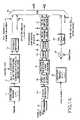
- FIGS. 1A and 1Bare block diagrams of a downlink transmitter for a DTCH according to an embodiment of the present invention.
- the downlink transmitter for a DTCHis characterized by transmission of a preamble sub-channel (PSCH) signal, a data traffic sub-channel (DTSCH) signal, and a pilot channel (PICH) signal in time division multiplexing (TDM).
- PSCHpreamble sub-channel
- DTSCHdata traffic sub-channel
- PICHpilot channel
- a signal point mapper 11maps preamble symbols to +1 s or ⁇ 1 s.
- a Walsh spreader 12spreads symbols received from the signal point mapper 11 with a 64-ary biorthogonal Walsh code (or sequence) corresponding to a user-specific MAC ID (Identification) (or index) and outputs a first channel sequence and a second channel sequence.
- a sequence repeater 13repeats the channel sequences according to a transmission rate. Since the repetition time is up to 16, a PSCH signal can last for 64 to 1024 chips in one slot of a DTCH.
- a time division multiplexer (TDM)25 multiplexes (I, Q) sequences received from the sequence repeater 13 with PICH and DTSCH sequences.
- a scrambler 14scrambles a channel-coded bit sequence and a channel interleaver 15 interleaves the output sequence of the scrambler 14 .
- the size of the channel interleaver 15varies with the length of a PLP.
- An M-ary symbol modulator 16operating as a QPSK (Quadrature Phase Shift Keying), 8-PSK (Phase Shift Keying), or 16-QAM (Quadrature Amplitude Modulation) modulator according to a transmission rate, modulates the interleaved symbols to M-ary symbols.
- the M-ary symbol modulator 16may use a different modulation scheme on a PLP basis on which a transmission rate is changed.
- a sequence repeater/symbol puncturer 17performs sequence repetition and symbol puncturing on (I, Q) sequences of the M-ary symbols output from the M-ary symbol modulator 16 .
- a symbol demultiplexer (DEMUX) 18demultiplexes the output of the sequence repeater/symbol puncturer 17 using one of N Walsh codes available to the DTSCH.
- Nis variable and the mobile station determines a transmission rate for the base station according to N. The mobile station reports the determined transmission rate to the base station, that is, requests the determined transmission rate to the base station. Therefore, the mobile station can find out what Walsh code is assigned to the current received DTSCH.
- a Walsh spreader 19spreads (I, Q) symbols received from the symbol DEMUX 18 with a predetermined Walsh code according to the channels.
- a Walsh channel gain controller 20controls the gains of (I, Q) sequences received from the Walsh spreader 19 .
- a Walsh chip level summer 21sums N (I, Q) sequences received from the Walsh channel gain controller 20 in chips.
- the TDM 25multiplexes the summed (I, Q) chip sequence with the PICH and the PSCH.
- a signal point mapper 22maps pilot symbols to +1 s and ⁇ 1 s.
- a Walsh spreader 23spreads the output symbols of the signal point mapper 22 with a 128-ary Walsh code assigned to the PICH.
- a PICH gain controller 24controls the gain of a sequence received from the Walsh spreader 23 .
- An I chip sequence output from the PICH gain controller 24is multiplexed with the PSCH and the DTSCH in the TDM 25 .
- the TDM 25multiplexes the I channel signal of the PICH received from the sequence repeater 13 , the I channel signal of the DTSCH received from the Walsh chip level summer 21 , and the I channel signal of the PSCH received from the gain controller 24 and outputs the multiplexed signal as signal A.
- the TDM 25also multiplexes the Q channel signal of the PICH received from the sequence repeater 13 , the Q channel signal of the DTSCH received from the Walsh chip level summer 21 , and the Q channel signal of the PSCH being 0 and outputs the multiplexed signal as signal B.
- a first summer 26sums the first channel signal components, namely, the I channel signal components of the DTCH, a DTMACCH (Data Traffic MAC Channel), and a CPCCH (Common Power Control Channel) at a chip level.
- the I channel signal component of the DTCHis signal A output from the TDM 25 shown in FIG. 1A .
- a second summer 27sums the second channel signal components, namely, the Q channel signal components of the DTCH, the DTMACCH, and the CPCCH at a chip level.
- the Q channel signal component of the DTCHis signal B output from the TDM 25 shown in FIG. 1A .
- a quadrature spreader 28complex-spreads (or complex-multiplies) the I and Q channel signals received from the first and second summers 26 and 27 with a first channel (I-ch) spreading sequence and a second channel (Q-ch) spreading sequence, respectively.
- Baseband filters 29 and 30baseband-filter a first channel signal and a second channel signal received from the quadrature spreader 28 , respectively.
- a first frequency upconverter 31upconverts the output of the baseband filter 29 to an RF (Radio Frequency) band by multiplying it by cos 2 ⁇ fct.
- a second frequency upconverter 32upconverts the output of the baseband filter 30 to an RF (Radio Frequency ) band by multiplying it by sin 2 ⁇ fct.
- a summer 33sums the output signals of the first and second frequency upconverters 31 and 32 . The summed signal is transmitted through an antenna (not shown).
- FIG. 2is a block diagram of a downlink receiver for a DTCH in a mobile station supporting multimedia service according to the present invention.
- an I channel component X and a Q channel component Y output from a quadrature despreaderare applied to the input of a DEMUX 35 .
- the DEMUX 35TDM-demultiplexes a DTSCH, a PSCH, and a PICH. Since the PICH occupies a fixed position in each slot, the DTSCH and the PSCH are transmitted in the remainder of the slot with the PSCH followed by the DTSCH.
- the PSCH separated in the DEMUX 35has a variable length according to the data rate of a corresponding downlink signal as described before with reference to FIGS. 1A and 1B .
- the PSCHwas spread with a 64-ary biorthogonal Walsh code corresponding to the MAC ID of a user to receive the downlink signal and transmitted on the I and Q channels according to the user MAC ID.
- a Walsh despreader 51despreads the PSCH signal with the 64-ary biorthogonal Walsh code.
- a channel compensator 52channel-compensates the output signal of the Walsh despreader 51 using estimated channel information representing an I channel component U and a Q channel component V
- a symbol combiner 53combines only the I or Q channel components of the channel-compensated signal according to a MAC index corresponding to the user MAC ID.
- a user detector 54received the combined signal from the symbol combiner 53 and determines whether the received downlink signal is for the user.
- the PICH signal of 256 chips per slotis separated in the DEMUX 35 .
- a mixer 43multiplies the PICH signal received from the DEMUX 35 with a Walsh code assigned to the PICH.
- a channel compensator 44channel-compensates the signal received from the mixer 43 using the estimated channel information representing the I channel component U and the Q channel component V in order to recover the signal loaded on the pilot channel.
- a demodulator 45demodulates the channel-compensated signal to burst pilot data.
- a CIR measurer 46receives the signal from the mixer 43 and provides an amplitude reference point for QAM demodulation when packet data is QAM-modulated.
- the DTSCHis positioned in the remainder of one slot except for portions for the pilot channel signal and the PSCH signal.
- the DTSCH signalis separated in the DEMUX 35 .
- a Walsh despreader 36despreads the DTSCH signal with a Walsh code assigned to the DTSCH and outputs as many parallel signals as the length of the Walsh code.
- a channel compensator 37channel-compensates the output of the Walsh despreader 36 using the estimated channel information representing the I channel component U and the Q channel component V
- a parallel-to-serial converter (PSC) 38converts the parallel signals received from the channel compensator 37 to a serial signal and a symbol combiner/inserter 39 performs symbol combining or symbol insertion on the serial signal received from the PSC 38 in correspondence with repetition and puncturing in a base station.
- a QPSK/8PSK/16QAM demodulator 40performs QPSK/8PSK/16QAM demodulation on the output of the symbol combiner/inserter 39 .
- a deinterleaver 41deinterleaves the demodulated signal in the reverse operation of interleaving in an interleaver of the base station.
- a turbo decoder 42turbo-decodes the deinterleaved signal, thereby extracting information bits.
- the present inventionprovides a method of determining whether a PLP is transmitted in a single format or in a double format.
- the mobile stationrequests a transmission rate change in a predetermined unit to the base station.
- the base stationthen monitors the change history of the mobile station-requested transmission rate and represents it numerically.
- the base stationcollects the numerically expressed change history of the transmission rate and determines whether to transmit data in a single format or in a double format.
- a descriptionis made below of an algorithm of making such a determination and a method of reporting the format of a transmitted PLP to a mobile station.
- FIG. 3is a block diagram of a base station for representing the change history of a mobile station-requested transmission rate numerically according to the embodiment of the present invention.
- the mobile stationtransmits a channel state value corresponding to an intended transmission rate to the base station on a uplink DRQSCH (Data Rate request Subchannel).
- the channel state valuemay be represented by index R m .
- R mis input to a first memory 101 in the base station.
- the subscript m of R mindicates the sequence number of a slot being 1.25 ms in duration.
- the base stationhas N memories 191 , 111 , 121 , . . . , 131 and 141 for storing indexes corresponding to transmission rates received from the mobile station on the uplink DRQSCH.
- Each memoryis a shift register that is activated in response to a clock signal of a period being the slot duration, 1.25 ms.
- R m of the first memory 101 and the negative of the second memory 111are ⁇ R m-1 , are output and applied to the input of a first adder 103 .
- the first adder 103outputs the difference between R m and R m-1 .
- R m-1(that is, the sum of R m and ⁇ R m-1 . ⁇ R m-1 ).
- the output of the first adder 103is fed to a first calculator 105 .
- R m-1 of the second memory 111 and the negative of the third memory, ⁇ R m-2are output and applied to the input of a second adder 113 .
- the second adder 113outputs the difference between R m-1 and R m-2.
- the output of the second adder 113is fed to a second calculator 115 .
- the difference between indexes received every 1.25 ms slot periodis calculated and fed to a corresponding calculator.
- R m-N+2 of the fourth memory 131 and the negative of the fifth memory 141, ⁇ R m-N+1are output and applied to the input of a third adder 133 .
- the third adder 133outputs the difference between R m-N+2 and R m-N+1 .
- the output of the third adder 133is fed to a third calculator 135 .
- (1) or f ( n )
- Eq. (1)represents the absolute value of an input value and Eq. (2) represents the square of an input value.
- Each calculatorreceives an integer value. Therefore, for the input of the same value, Eq. (2) produces the same value as or a higher value than Eq. (1).
- a calculator based on Eq. (2)outputs a higher value than a calculator based on Eq. (1).
- Eq. (2)offers a greater weight during numerical representation of changes in a transmission rate as the mobile station-requested transmission rate is drastically changed.
- any other operation that can estimate the change of a transmission rate using the difference between indexes in a 1.25 ms slot periodcan be applied.
- a fourth adder 107sums the outputs of calculators 105 to 135 and outputs the sum as a numerical value representing the change history of the mobile station-requested transmission rate, by which it can be determined whether data is to be transmitted in a single format or in a double format.
- the adder 107performs the summation by
- Eq. (3)has been given as an embodiment of representing the change history of a mobile station-requested transmission rate as a numerical value, any other operation can be used as long as it represents the change history of the transmission rate numerically using the different between indexes received in a 1.25 ms slot period.
- the adder 107performs the summation by
- Eq. (4)has been given as another embodiment of representing the change history of a mobile station-requested transmission rate as a numerical value, any other operation can be used as long as it represents the change history of the transmission rate numerically using the different between indexes received in a 1.25 ms slot period.
- the calculation portion 100produces a numerical value representing the change history of a mobile station-requested transmission rate by Eq. (3) or Eq. (4).
- a controller 109checks the change history of the transmission rate by receiving the calculation result ⁇ of Eq. (3) or Eq. (4).
- the received value ⁇is compared with a predetermined threshold ⁇ and the format of a PLP is determined according to the comparison result in a later-described method.
- FIG. 4is a flowchart illustrating a data transmission method according to the embodiment of the present invention.
- an index mis set to 0 in step 202 .
- mis the sequence number of a slot being 1.25 ms in duration.
- the base stationincreases the index m by 1 every time it receives an index corresponding to a mobile station-requested transmission rate in the 1.25 ms slot period.
- the base stationcompares the index m with a predetermined value N in step 204 .
- Nis a time period for which transmission rate changes are monitored and is equal to the number of the memories shown in FIG. 3 . If m is greater than or equal to N, the procedure goes to step 205 and if m is less than N, it goes to step 215 . This implies that PLP data transmission a predetermined time after the algorithm starts is limited to a single format.
- step 205the base station calculates the differences between sequentially received mobile station-requested transmission rates and obtains a numerical value ⁇ representing the change history of the mobile station-requested transmission rate by processing the differences in an operation that offers the change history of the transmission rate as a numerical value. Then the base station checks whether a new PLP is to be transmitted in step 206 . If the base station is supposed to transmit a new PLP, it goes to step 207 and if not, it returns to step 203 , which implies that a transmitted PLP is to be retransmitted due to a reception error or some PLP is being transmitted.
- step 207the base station compares the value ⁇ with a predetermined threshold ⁇ . If ⁇ is less than ⁇ , the procedure goes to step 208 and if ⁇ is greater than or equal to ⁇ , the procedure goes to step 219 .
- step 208the base station checks whether sufficient information data exists in a buffer to construct a double-formatted PLP. If a double-formatted PLP can be constructed with the information data in the buffer, the procedure goes to step 209 and, otherwise, the procedure goes to step 219 .
- step 209the base station constructs a PLP with the information data stored in the buffer in a double format according to a mobile station-requested transmission rate and initiates data transmission. The procedure then returns to step 203 .
- step 216the base station checks whether it is time to transmit a new PLP. If a new PLP is to be transmitted, step 219 is performed and otherwise, step 203 is performed. That is, step 203 is carried out in the case where a transmitted PLP is to be retransmitted due to a reception error or some PLP is being transmitted.
- step 219the base station constructs a PLP with the information data of the buffer in a single format according to a mobile station-requested transmission rate and initiates data transmission. The procedure then returns to step 203 .
- the mobile stationis provided with the components shown in FIG. 3 and operates in the algorithm shown in FIG. 4 , so that it can find out the format of a received PLP.
- This methodadvantageously obviates the need of notifying the mobile station of the format of the PLP by the base station.
- the second embodimentuses a burst pilot transmitted on a PICH.
- a burst pilotexists in a predetermined time period of a downlink data transmission slot in a mobile telecommunication system to which the present invention is applied.
- a burst pilot symbolis 0 (or burst pilot symbols are all 0 s) and spread with a predetermined Walsh code prior to transmission.
- the mobile stationcan measure the CIR of a mobile communication channel between the base station and mobile station and obtain an amplitude reference necessary to demodulate a 16QAM-modulated signal.
- a common pilotwhich is provided in an existing IS-95 mobile telecommunication system, as well as the burst pilot is used for the downlink.
- the burst pilot symbolcan be 0 or 1 (the burst pilot symbols are all 0 s or 1 s) and transmit one-bit information. That is, the base station can report the mobile station of the format of a current transmitted PLP by setting the burst pilot symbol to 0 or 1.
- FIG. 5Ais a block diagram of a downlink transmitter for transmitting one-bit information on a modified PICH, by which the format of a transmitted PLP is determined between a single format and a double format.
- a pilot symbolis set to 0 or 1 depending on whether a PLP to be transmitted is in a single format or in a double format.
- a signal point mapper 301maps the pilot symbol 0 or 1 to +1 or ⁇ 1 under the control of a controller 304 .
- the controller 304is the same as the controller 109 shown in FIG. 3 in operation and structure.
- the pilot symbolis set to 0 or 1. If the pilot symbol is 0, it indicates that the PLP is transmitted in the single format and if the pilot symbol is 1, it indicates that the PLP is transmitted in the double format, or vice versa.
- a Walsh spreader 302spreads the output of the signal point mapper 301 with a Walsh code assigned to the PICH.
- a PICH gain controller 303controls the gain of the spread sequence received from the Walsh spreader 302 .
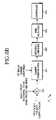
- FIG. 5Bis a block diagram of a mobile station receiver for detecting a data transmission method as the counterpart of the transmitter shown in FIG. 5A .
- a Walsh despreader 401despreads a signal received from a DEMUX (not shown) for a DTCH with the same Walsh code as used in the base station.
- a channel compensator 402channel-compensates the spread signal using a channel estimated value received from a channel estimator (not shown).
- a coherent demodulator 403 for a pilot symboloutputs 0 or 1 for the input of the channel-compensated signal.
- a controller 404determines whether a received PLP is in a single format or a double format according to the bit received from the coherent demodulator 403 . For an input bit of 0, the controller 404 determines that the PLP is in the single format and for an input bit of 1, it determines that the PLP is in the double format. That is, the controller 404 can find out the format of a current signal which was transmitted after mapping from the base station. This will be described later in more detail referring to FIG. 7 .
- a preamble transmitted on a PSCHis used.
- the base stationtransmits a preamble at the start of each PLP.
- the preambleis set to 0 or 1 depending on the format of the PLP and spread with an orthogonal Walsh code.
- FIG. 6Ais a block diagram of a downlink transmitter for transmitting a preamble representing the format of a transmitted PLP.
- the base stationsets a preamble symbol to 0 or 1 according to the format of a PLP to be transmitted.
- a signal point mapper 501maps the preamble symbol 0 or 1 to +1 or ⁇ 1.
- the preamble symbol value to be mappedis received from a controller 503 , which was determined in the operations of FIGS. 3 and 4 .
- the controller 504is the same as the controller 109 of FIG. 3 in operation and structure.
- the transmission format of a PLPcan be reported to a mobile station.
- a value representing the result of a determination made by the algorithm shown in FIG. 4 using information extracted from the structure of FIG. 3is output in the manner shown in FIG. 5A or FIG. 6A .
- a Walsh spreader 502spreads the output symbols of the signal point mapper 501 with an orthogonal Walsh code or sequence corresponding to a user-specific MAC ID or index.
- a sequence repeater 503repeats the spread sequence according to a transmission rate. For the base station to notify the mobile station of the format of a PLP to be transmitted via a PSCH, the mobile station has a receiver that can demodulate the PSCH.
- FIG. 6Bis a block diagram of a receiver for receiving a preamble in the case where information about the format of a transmitted PLP is transmitted via the preamble as shown in FIG. 6A .
- a Walsh despreader 601despreads a signal received from a DEMUX (not shown) for a DTCH with a Walsh code corresponding to a user-specific MAC ID.
- a channel compensator 602channel-compensates the despread signal using a channel estimated value received from a channel estimator (not shown).
- a sequence combiner 603combines sequences according to the repetition time of sequences determined by a transmission rate.
- a detector 604receives the output of the sequence combiner 603 and checks whether the received PLP is for the mobile station using the MAC ID.
- a controller 605extracts PLP information and performs data reception in the single format or in the double format according to a bit indicating the format of the PLP. For example, if the bit is 0, the controller 605 sets a data reception mode to a single format and if the bit is 1, it sets a data reception mode to a double format.
- the PLP reception in a receiverwill be described below referring to FIG. 7 .
- FIG. 7is a flowchart illustrating a control operation for changing a PLP data reception mode in a receiver according to the embodiments of the present invention. The following description is made with appreciation that a controller in the receiver acts as the controller 404 of FIG. 5B or the controller 605 of FIG. 6B according to a reception mode.
- the controlleris in a PLP reception state in which a PLP can be received in a single format or in a double format in step 700 , and receives PLP-related information in step 702 .
- the PLP-related informationis a bit indicating the format of a PLP, received in the manner shown in FIG. 5B or FIG. 6B .
- the controllerchecks whether the bit is 0, that is, whether the PLP was transmitted in a single format or in a double format. If the bit is 0, the controller sets the receiver to a single format PLP reception mode in step 706 and returns to step 700 . If the bit is 1, the controller sets the receiver to a double format PLP reception mode in step 708 and returns to step 700 .
- the mobile stationcan find out the format of a PLP transmitted from the base station and sets the receiver to a corresponding reception mode. Therefore, the receiver can receive data without errors.
Landscapes
- Engineering & Computer Science (AREA)
- Computer Networks & Wireless Communication (AREA)
- Signal Processing (AREA)
- Quality & Reliability (AREA)
- Physics & Mathematics (AREA)
- Probability & Statistics with Applications (AREA)
- Mobile Radio Communication Systems (AREA)
Abstract
Description
f(n)=|n| (1)
orf(n)=|n|2. . . (2)
Claims (15)
Applications Claiming Priority (2)
| Application Number | Priority Date | Filing Date | Title |
|---|---|---|---|
| KR2000-83395 | 2000-12-27 | ||
| KR1020000083395AKR100754633B1 (en) | 2000-12-27 | 2000-12-27 | Transceiver and Method for Packet Data Service in Mobile Communication System |
Publications (2)
| Publication Number | Publication Date |
|---|---|
| US20020122431A1 US20020122431A1 (en) | 2002-09-05 |
| US7283559B2true US7283559B2 (en) | 2007-10-16 |
Family
ID=19703725
Family Applications (1)
| Application Number | Title | Priority Date | Filing Date |
|---|---|---|---|
| US10/032,576Expired - Fee RelatedUS7283559B2 (en) | 2000-12-27 | 2001-12-27 | Transmitting/receiving apparatus and method for packet data service in a mobile telecommunication system |
Country Status (5)
| Country | Link |
|---|---|
| US (1) | US7283559B2 (en) |
| EP (1) | EP1256186B1 (en) |
| KR (1) | KR100754633B1 (en) |
| DE (1) | DE60106205T2 (en) |
| WO (1) | WO2002052741A1 (en) |
Cited By (30)
| Publication number | Priority date | Publication date | Assignee | Title |
|---|---|---|---|---|
| US20070104174A1 (en)* | 2003-12-12 | 2007-05-10 | Johan Nystrom | Method and apparatus for allocating a pilot signal adapted to the channel characteristics |
| US20090109911A1 (en)* | 2007-10-26 | 2009-04-30 | The University Of Bristol | Obtaining channel feedback from users in a wireless communication system |
| US8102832B2 (en) | 2003-05-12 | 2012-01-24 | Qualcomm Incorporated | Fast frequency hopping with a code division multiplexed pilot in an OFDMA system |
| US8238923B2 (en) | 2004-12-22 | 2012-08-07 | Qualcomm Incorporated | Method of using shared resources in a communication system |
| US8437251B2 (en) | 2005-12-22 | 2013-05-07 | Qualcomm Incorporated | Methods and apparatus for communicating transmission backlog information |
| US8503938B2 (en) | 2004-10-14 | 2013-08-06 | Qualcomm Incorporated | Methods and apparatus for determining, communicating and using information including loading factors which can be used for interference control purposes |
| US8514692B2 (en) | 2003-02-24 | 2013-08-20 | Qualcomm Incorporated | Methods and apparatus for determining, communicating and using information which can be used for interference control purposes |
| US8514771B2 (en) | 2005-12-22 | 2013-08-20 | Qualcomm Incorporated | Methods and apparatus for communicating and/or using transmission power information |
| US8611283B2 (en) | 2004-01-28 | 2013-12-17 | Qualcomm Incorporated | Method and apparatus of using a single channel to provide acknowledgement and assignment messages |
| US8638870B2 (en) | 2004-12-22 | 2014-01-28 | Qualcomm Incorporated | MC-CDMA multiplexing in an orthogonal uplink |
| US8694042B2 (en) | 2005-10-14 | 2014-04-08 | Qualcomm Incorporated | Method and apparatus for determining a base station's transmission power budget |
| US8724555B2 (en) | 2002-10-29 | 2014-05-13 | Qualcomm Incorporated | Uplink pilot and signaling transmission in wireless communication systems |
| US8811348B2 (en) | 2003-02-24 | 2014-08-19 | Qualcomm Incorporated | Methods and apparatus for generating, communicating, and/or using information relating to self-noise |
| US8965413B2 (en) | 2006-04-12 | 2015-02-24 | Qualcomm Incorporated | Locating a wireless local area network associated with a wireless wide area network |
| US9119220B2 (en) | 2005-12-22 | 2015-08-25 | Qualcomm Incorporated | Methods and apparatus for communicating backlog related information |
| US9125092B2 (en) | 2005-12-22 | 2015-09-01 | Qualcomm Incorporated | Methods and apparatus for reporting and/or using control information |
| US9125093B2 (en) | 2005-12-22 | 2015-09-01 | Qualcomm Incorporated | Methods and apparatus related to custom control channel reporting formats |
| US9137072B2 (en) | 2005-12-22 | 2015-09-15 | Qualcomm Incorporated | Methods and apparatus for communicating control information |
| US9148795B2 (en) | 2005-12-22 | 2015-09-29 | Qualcomm Incorporated | Methods and apparatus for flexible reporting of control information |
| US9185013B1 (en)* | 2002-02-13 | 2015-11-10 | Marvell International Ltd. | Systems and methods for compensating a channel estimate for sampling phase jitter |
| US9191840B2 (en) | 2005-10-14 | 2015-11-17 | Qualcomm Incorporated | Methods and apparatus for determining, communicating and using information which can be used for interference control |
| US9338767B2 (en) | 2005-12-22 | 2016-05-10 | Qualcomm Incorporated | Methods and apparatus of implementing and/or using a dedicated control channel |
| US9338795B2 (en) | 2005-12-22 | 2016-05-10 | Qualcomm Incorporated | Methods and apparatus for communicating transmission backlog information |
| US9451491B2 (en) | 2005-12-22 | 2016-09-20 | Qualcomm Incorporated | Methods and apparatus relating to generating and transmitting initial and additional control information report sets in a wireless system |
| US9462604B2 (en) | 2005-12-22 | 2016-10-04 | Qualcomm Incorporated | Methods and apparatus related to selecting a request group for a request report |
| US9473265B2 (en) | 2005-12-22 | 2016-10-18 | Qualcomm Incorporated | Methods and apparatus for communicating information utilizing a plurality of dictionaries |
| US9480074B2 (en) | 2004-07-23 | 2016-10-25 | Qualcomm Incorporated | Enabling quick and easy demodulation |
| US9544860B2 (en) | 2003-02-24 | 2017-01-10 | Qualcomm Incorporated | Pilot signals for use in multi-sector cells |
| US9603102B2 (en) | 2003-02-24 | 2017-03-21 | Qualcomm Incorporated | Method of transmitting pilot tones in a multi-sector cell, including null pilot tones, for generating channel quality indicators |
| US10959120B2 (en) | 2005-12-22 | 2021-03-23 | Qualcomm Incorporated | Methods and apparatus related to selecting control channel reporting formats |
Families Citing this family (10)
| Publication number | Priority date | Publication date | Assignee | Title |
|---|---|---|---|---|
| US6782269B2 (en)* | 2002-06-17 | 2004-08-24 | Nokia Corporation | Two threshold uplink rate control to enable uplink scheduling |
| US9661519B2 (en)* | 2003-02-24 | 2017-05-23 | Qualcomm Incorporated | Efficient reporting of information in a wireless communication system |
| TWI297987B (en)* | 2004-11-23 | 2008-06-11 | Miracom Technology Co Ltd | The apparatus for providing data service between mobile and mobile in wireless communication system |
| ES2534828T3 (en)* | 2005-12-22 | 2015-04-29 | Qualcomm Incorporated | Procedure and apparatus for notifying information in a wireless communications system |
| US8472309B2 (en)* | 2008-08-20 | 2013-06-25 | Qualcomm Incorporated | Using CDMA to send uplink signals in WLANs |
| KR101138589B1 (en)* | 2010-08-25 | 2012-05-10 | 한국과학기술원 | Method and apparatus for transmitting sensor information |
| KR102127685B1 (en)* | 2013-04-17 | 2020-06-29 | 삼성전자주식회사 | Apparatus and method for transmitting and receiving forward error correction packet |
| EP3090333A4 (en)* | 2013-12-30 | 2017-07-12 | Schneider Electric IT Corporation | System and method for automatically selecting baud rate in a can network |
| WO2021221188A1 (en)* | 2020-04-28 | 2021-11-04 | 엘지전자 주식회사 | Signal processing device and image display device including same |
| CN119892749A (en)* | 2020-04-30 | 2025-04-25 | 中兴通讯股份有限公司 | Cell stream characteristic value adjusting method, device, system and storage medium |
Citations (8)
| Publication number | Priority date | Publication date | Assignee | Title |
|---|---|---|---|---|
| EP0986282A1 (en) | 1998-04-17 | 2000-03-15 | Matsushita Electric Industrial Co., Ltd. | Radio communication device and method of controlling transmission rate |
| WO2000014900A1 (en) | 1998-09-10 | 2000-03-16 | Qualcomm Incorporated | Method and apparatus for distributed optimal reverse link scheduling of resources, such as rate and power, in a wireless communication system |
| US6088335A (en) | 1995-10-05 | 2000-07-11 | Lucent Technologies Inc. | Code division multiple access system providing load and interference based demand assignment service to users |
| EP1043910A2 (en) | 1999-04-08 | 2000-10-11 | Lucent Technologies Inc. | Burst duration assignment based on fading fluctuation and mobility in wireless communication systems |
| US6253063B1 (en) | 2000-01-25 | 2001-06-26 | Motorola, Inc. | Method and apparatus for selecting a communication data rate between mobile and base stations |
| US20010017851A1 (en) | 2000-01-24 | 2001-08-30 | Ddi Corporation | Mobile communication system having adaptively assigned packet rate |
| US20020097780A1 (en)* | 2000-11-30 | 2002-07-25 | Odenwalder Joseph P. | Preamble generation |
| US6452936B1 (en)* | 1997-11-17 | 2002-09-17 | Oki Electric Industry Co., Ltd. | Spread-spectrum communication apparatus with adaptive frame configuration |
Family Cites Families (8)
| Publication number | Priority date | Publication date | Assignee | Title |
|---|---|---|---|---|
| US5933607A (en)* | 1993-06-07 | 1999-08-03 | Telstra Corporation Limited | Digital communication system for simultaneous transmission of data from constant and variable rate sources |
| US5818826A (en)* | 1996-06-17 | 1998-10-06 | International Business Machines Corporation | Media access control protocols in a wireless communication network supporting multiple transmission rates |
| EP0828394B1 (en)* | 1996-09-06 | 2006-05-03 | Samsung Electronics Co., Ltd. | A device and method for converting data transfer rate in communication of digital audio/video data |
| US5982807A (en)* | 1997-03-17 | 1999-11-09 | Harris Corporation | High data rate spread spectrum transceiver and associated methods |
| US6501745B1 (en)* | 1998-02-13 | 2002-12-31 | Telefonaktiebolaget Lm Ericsson (Publ) | Method for variable block scheduling indication by an uplink state flag in a packet data communication system |
| AU5274401A (en)* | 2000-04-21 | 2001-11-07 | Samsung Electronics Co Ltd | Flexible data rate matching apparatus and method in a data communication system |
| US7068627B2 (en)* | 2000-10-19 | 2006-06-27 | Samsung Electronics Co., Ltd. | Device and method for transmitting data with different qualities in mobile communication system |
| KR20020031026A (en)* | 2000-10-20 | 2002-04-26 | 윤종용 | Apparatus and method for determining data rate of packet data and modulation/demodulation parameter adaptively in mobile communications system supporting voice and packet data services |
- 2000
- 2000-12-27KRKR1020000083395Apatent/KR100754633B1/ennot_activeExpired - Fee Related
- 2001
- 2001-12-27EPEP01272383Apatent/EP1256186B1/ennot_activeExpired - Lifetime
- 2001-12-27USUS10/032,576patent/US7283559B2/ennot_activeExpired - Fee Related
- 2001-12-27DEDE60106205Tpatent/DE60106205T2/ennot_activeExpired - Fee Related
- 2001-12-27WOPCT/KR2001/002279patent/WO2002052741A1/ennot_activeCeased
Patent Citations (8)
| Publication number | Priority date | Publication date | Assignee | Title |
|---|---|---|---|---|
| US6088335A (en) | 1995-10-05 | 2000-07-11 | Lucent Technologies Inc. | Code division multiple access system providing load and interference based demand assignment service to users |
| US6452936B1 (en)* | 1997-11-17 | 2002-09-17 | Oki Electric Industry Co., Ltd. | Spread-spectrum communication apparatus with adaptive frame configuration |
| EP0986282A1 (en) | 1998-04-17 | 2000-03-15 | Matsushita Electric Industrial Co., Ltd. | Radio communication device and method of controlling transmission rate |
| WO2000014900A1 (en) | 1998-09-10 | 2000-03-16 | Qualcomm Incorporated | Method and apparatus for distributed optimal reverse link scheduling of resources, such as rate and power, in a wireless communication system |
| EP1043910A2 (en) | 1999-04-08 | 2000-10-11 | Lucent Technologies Inc. | Burst duration assignment based on fading fluctuation and mobility in wireless communication systems |
| US20010017851A1 (en) | 2000-01-24 | 2001-08-30 | Ddi Corporation | Mobile communication system having adaptively assigned packet rate |
| US6253063B1 (en) | 2000-01-25 | 2001-06-26 | Motorola, Inc. | Method and apparatus for selecting a communication data rate between mobile and base stations |
| US20020097780A1 (en)* | 2000-11-30 | 2002-07-25 | Odenwalder Joseph P. | Preamble generation |
Non-Patent Citations (1)
| Title |
|---|
| European Search Report dated Apr. 3, 2003, issued in a counterpart application, namely, Appln. No. 01272383.9. |
Cited By (50)
| Publication number | Priority date | Publication date | Assignee | Title |
|---|---|---|---|---|
| US9185013B1 (en)* | 2002-02-13 | 2015-11-10 | Marvell International Ltd. | Systems and methods for compensating a channel estimate for sampling phase jitter |
| US9155106B2 (en) | 2002-10-29 | 2015-10-06 | Qualcomm Incorporated | Uplink pilot and signaling transmission in wireless communication systems |
| US8724555B2 (en) | 2002-10-29 | 2014-05-13 | Qualcomm Incorporated | Uplink pilot and signaling transmission in wireless communication systems |
| US8514692B2 (en) | 2003-02-24 | 2013-08-20 | Qualcomm Incorporated | Methods and apparatus for determining, communicating and using information which can be used for interference control purposes |
| US9544860B2 (en) | 2003-02-24 | 2017-01-10 | Qualcomm Incorporated | Pilot signals for use in multi-sector cells |
| US8811348B2 (en) | 2003-02-24 | 2014-08-19 | Qualcomm Incorporated | Methods and apparatus for generating, communicating, and/or using information relating to self-noise |
| US9603102B2 (en) | 2003-02-24 | 2017-03-21 | Qualcomm Incorporated | Method of transmitting pilot tones in a multi-sector cell, including null pilot tones, for generating channel quality indicators |
| US8102832B2 (en) | 2003-05-12 | 2012-01-24 | Qualcomm Incorporated | Fast frequency hopping with a code division multiplexed pilot in an OFDMA system |
| US11265126B2 (en) | 2003-12-12 | 2022-03-01 | Telefonaktiebolaget Lm Ericsson (Publ) | Method and apparatus for allocating a pilot signal adapted to the channel characteristics |
| US9935749B2 (en) | 2003-12-12 | 2018-04-03 | Telefonaktiebolaget Lm Ericsson (Publ) | Method and apparatus for allocating a pilot signal adapted to the channel characteristics |
| US20070104174A1 (en)* | 2003-12-12 | 2007-05-10 | Johan Nystrom | Method and apparatus for allocating a pilot signal adapted to the channel characteristics |
| US10560236B2 (en) | 2003-12-12 | 2020-02-11 | Telefonaktiebolaget Lm Ericsson (Publ) | Method and apparatus for allocating a pilot signal adapted to the channel characteristics |
| US20110075625A1 (en)* | 2003-12-12 | 2011-03-31 | Telefonaktiebolaget Lm Ericsson (Publ), Stockholm | Method and apparatus for allocating a pilot signal adapted to the channel characteristics |
| US7904093B2 (en)* | 2003-12-12 | 2011-03-08 | Telefonaktiebolaget Lm Ericsson (Publ) | Method and apparatus for allocating a pilot signal adapted to the channel characteristics |
| US12010057B2 (en) | 2003-12-12 | 2024-06-11 | Telefonaktiebolaget Lm Ericsson (Publ) | Method and apparatus for allocating a pilot signal adapted to the channel characteristics |
| US8843144B2 (en) | 2003-12-12 | 2014-09-23 | Telefonaktiebolaget L M Ericsson (Publ) | Method and apparatus for allocating a pilot signal adapted to the channel characteristics |
| US8611283B2 (en) | 2004-01-28 | 2013-12-17 | Qualcomm Incorporated | Method and apparatus of using a single channel to provide acknowledgement and assignment messages |
| US9871617B2 (en) | 2004-07-23 | 2018-01-16 | Qualcomm Incorporated | Method of optimizing portions of a frame |
| US9480074B2 (en) | 2004-07-23 | 2016-10-25 | Qualcomm Incorporated | Enabling quick and easy demodulation |
| US8503938B2 (en) | 2004-10-14 | 2013-08-06 | Qualcomm Incorporated | Methods and apparatus for determining, communicating and using information including loading factors which can be used for interference control purposes |
| US8649451B2 (en) | 2004-12-22 | 2014-02-11 | Qualcomm Incorporated | MC-CDMA multiplexing in an orthogonal uplink |
| US8238923B2 (en) | 2004-12-22 | 2012-08-07 | Qualcomm Incorporated | Method of using shared resources in a communication system |
| US8638870B2 (en) | 2004-12-22 | 2014-01-28 | Qualcomm Incorporated | MC-CDMA multiplexing in an orthogonal uplink |
| US8817897B2 (en) | 2004-12-22 | 2014-08-26 | Qualcomm Incorporated | MC-CDMA multiplexing in an orthogonal uplink |
| US8831115B2 (en) | 2004-12-22 | 2014-09-09 | Qualcomm Incorporated | MC-CDMA multiplexing in an orthogonal uplink |
| US9191840B2 (en) | 2005-10-14 | 2015-11-17 | Qualcomm Incorporated | Methods and apparatus for determining, communicating and using information which can be used for interference control |
| US8694042B2 (en) | 2005-10-14 | 2014-04-08 | Qualcomm Incorporated | Method and apparatus for determining a base station's transmission power budget |
| US8989084B2 (en) | 2005-10-14 | 2015-03-24 | Qualcomm Incorporated | Methods and apparatus for broadcasting loading information corresponding to neighboring base stations |
| US9473265B2 (en) | 2005-12-22 | 2016-10-18 | Qualcomm Incorporated | Methods and apparatus for communicating information utilizing a plurality of dictionaries |
| US9578654B2 (en) | 2005-12-22 | 2017-02-21 | Qualcomm Incorporated | Methods and apparatus related to selecting reporting alternative in a request report |
| US9161313B2 (en) | 2005-12-22 | 2015-10-13 | Qualcomm Incorporated | Methods and apparatus for communicating and/or using transmission power information |
| US9338767B2 (en) | 2005-12-22 | 2016-05-10 | Qualcomm Incorporated | Methods and apparatus of implementing and/or using a dedicated control channel |
| US9338795B2 (en) | 2005-12-22 | 2016-05-10 | Qualcomm Incorporated | Methods and apparatus for communicating transmission backlog information |
| US9451491B2 (en) | 2005-12-22 | 2016-09-20 | Qualcomm Incorporated | Methods and apparatus relating to generating and transmitting initial and additional control information report sets in a wireless system |
| US9462604B2 (en) | 2005-12-22 | 2016-10-04 | Qualcomm Incorporated | Methods and apparatus related to selecting a request group for a request report |
| US9119220B2 (en) | 2005-12-22 | 2015-08-25 | Qualcomm Incorporated | Methods and apparatus for communicating backlog related information |
| US9148795B2 (en) | 2005-12-22 | 2015-09-29 | Qualcomm Incorporated | Methods and apparatus for flexible reporting of control information |
| US9137072B2 (en) | 2005-12-22 | 2015-09-15 | Qualcomm Incorporated | Methods and apparatus for communicating control information |
| US9572179B2 (en) | 2005-12-22 | 2017-02-14 | Qualcomm Incorporated | Methods and apparatus for communicating transmission backlog information |
| US8830827B2 (en) | 2005-12-22 | 2014-09-09 | Qualcomm Incorporated | Methods and apparatus for communicating transmission backlog information |
| US9125093B2 (en) | 2005-12-22 | 2015-09-01 | Qualcomm Incorporated | Methods and apparatus related to custom control channel reporting formats |
| US9125092B2 (en) | 2005-12-22 | 2015-09-01 | Qualcomm Incorporated | Methods and apparatus for reporting and/or using control information |
| US9893917B2 (en) | 2005-12-22 | 2018-02-13 | Qualcomm Incorporated | Methods and apparatus for communicating control information |
| US8514771B2 (en) | 2005-12-22 | 2013-08-20 | Qualcomm Incorporated | Methods and apparatus for communicating and/or using transmission power information |
| US10159006B2 (en) | 2005-12-22 | 2018-12-18 | Qualcomm Incorporated | Methods and apparatus for reporting and/or using control information |
| US8437251B2 (en) | 2005-12-22 | 2013-05-07 | Qualcomm Incorporated | Methods and apparatus for communicating transmission backlog information |
| US10645693B2 (en) | 2005-12-22 | 2020-05-05 | Qualcomm Incorporated | Methods and apparatus of implementing and/or using a control channel |
| US10959120B2 (en) | 2005-12-22 | 2021-03-23 | Qualcomm Incorporated | Methods and apparatus related to selecting control channel reporting formats |
| US8965413B2 (en) | 2006-04-12 | 2015-02-24 | Qualcomm Incorporated | Locating a wireless local area network associated with a wireless wide area network |
| US20090109911A1 (en)* | 2007-10-26 | 2009-04-30 | The University Of Bristol | Obtaining channel feedback from users in a wireless communication system |
Also Published As
| Publication number | Publication date |
|---|---|
| US20020122431A1 (en) | 2002-09-05 |
| KR20020053677A (en) | 2002-07-05 |
| DE60106205D1 (en) | 2004-11-11 |
| EP1256186A4 (en) | 2003-05-21 |
| EP1256186A1 (en) | 2002-11-13 |
| DE60106205T2 (en) | 2005-12-29 |
| WO2002052741A1 (en) | 2002-07-04 |
| EP1256186B1 (en) | 2004-10-06 |
| KR100754633B1 (en) | 2007-09-05 |
Similar Documents
| Publication | Publication Date | Title |
|---|---|---|
| US7283559B2 (en) | Transmitting/receiving apparatus and method for packet data service in a mobile telecommunication system | |
| AU736358B2 (en) | Subscriber unit for CDMA wireless communication system | |
| KR100401186B1 (en) | Apparatus and method for determining a data rate of packet data in mobile communication system | |
| EP0903019B1 (en) | Subscriber unit for a cdma wireless communication system | |
| AU752866B2 (en) | A subscriber unit and method for use in a wireless communication system | |
| US6987798B2 (en) | System and method for demodulating multiple Walsh codes using a chip combiner | |
| KR100474719B1 (en) | Apparatus and method for transmitting and receiving control information in mobile telecommunication system | |
| US6678311B2 (en) | High data CDMA wireless communication system using variable sized channel codes | |
| AU746537B2 (en) | A subscriber unit and method for use in a wireless communication system | |
| EP1234385A1 (en) | Apparatus and method for transmitting a burst pilot channel in a mobile communication system | |
| WO2005078964A1 (en) | Apparatus and method for allocating ovsf codes and i/q channels for reducing peak-to-average power ratio in transmitting data via enhanced up-link dedicated channels in wcdma systems | |
| EP1786131B1 (en) | Complex multiplexing transmission/reception apparatus and method in a wireless communication system | |
| KR20020031026A (en) | Apparatus and method for determining data rate of packet data and modulation/demodulation parameter adaptively in mobile communications system supporting voice and packet data services | |
| HK1020462B (en) | Subscriber unit for a cdma wireless communication system | |
| KR20050118082A (en) | Apparatus and method for allocating ovsf codes and i/q channels for reducing peak-to-average power ratio in transmitting data via enhanced up-link dedicated channels in wcdma systems | |
| HK1018993B (en) | Subscriber unit for cdma wireless communication system | |
| KR20050118064A (en) | Apparatus and method for allocating ovsf codes and i/q channels for reducing peak-to-average power ratio in transmitting data via enhanced up-link dedicated channels in wcdma systems | |
| HK1149860A (en) | A subscriber unit and method for use in a wireless communication system |
Legal Events
| Date | Code | Title | Description |
|---|---|---|---|
| AS | Assignment | Owner name:SAMSUNG ELECTRONICS, CO., LTD., KOREA, REPUBLIC OF Free format text:ASSIGNMENT OF ASSIGNORS INTEREST;ASSIGNORS:CHO, YOUNG-KWON;JANG, JAE-BUNG;REEL/FRAME:012423/0612 Effective date:20011227 | |
| AS | Assignment | Owner name:SAMSUNG ELECTRONICS, CO., LTD., KOREA, REPUBLIC OF Free format text:RE-RECORD TO CORRECT THE NAME OF THE SECOND ASSIGNOR, PREVIOUSLY RECORDED ON REEL 012423 FRAME 0612, ASSIGNOR CONFIRMS THE ASSIGNMENT OF THE ENTIRE INTEREST.;ASSIGNORS:CHO, YOUNG-KWON;JANG, JAE-SUNG;REEL/FRAME:012806/0219 Effective date:20011227 | |
| STCF | Information on status: patent grant | Free format text:PATENTED CASE | |
| FEPP | Fee payment procedure | Free format text:PAYOR NUMBER ASSIGNED (ORIGINAL EVENT CODE: ASPN); ENTITY STATUS OF PATENT OWNER: LARGE ENTITY | |
| FEPP | Fee payment procedure | Free format text:PAYOR NUMBER ASSIGNED (ORIGINAL EVENT CODE: ASPN); ENTITY STATUS OF PATENT OWNER: LARGE ENTITY Free format text:PAYER NUMBER DE-ASSIGNED (ORIGINAL EVENT CODE: RMPN); ENTITY STATUS OF PATENT OWNER: LARGE ENTITY | |
| FPAY | Fee payment | Year of fee payment:4 | |
| FPAY | Fee payment | Year of fee payment:8 | |
| FEPP | Fee payment procedure | Free format text:MAINTENANCE FEE REMINDER MAILED (ORIGINAL EVENT CODE: REM.); ENTITY STATUS OF PATENT OWNER: LARGE ENTITY | |
| LAPS | Lapse for failure to pay maintenance fees | Free format text:PATENT EXPIRED FOR FAILURE TO PAY MAINTENANCE FEES (ORIGINAL EVENT CODE: EXP.); ENTITY STATUS OF PATENT OWNER: LARGE ENTITY | |
| STCH | Information on status: patent discontinuation | Free format text:PATENT EXPIRED DUE TO NONPAYMENT OF MAINTENANCE FEES UNDER 37 CFR 1.362 | |
| FP | Lapsed due to failure to pay maintenance fee | Effective date:20191016 |