US7283355B2 - Portable computer - Google Patents
Portable computerDownload PDFInfo
- Publication number
- US7283355B2 US7283355B2US10/994,414US99441404AUS7283355B2US 7283355 B2US7283355 B2US 7283355B2US 99441404 AUS99441404 AUS 99441404AUS 7283355 B2US7283355 B2US 7283355B2
- Authority
- US
- United States
- Prior art keywords
- display part
- projection
- shaft
- main body
- portable computer
- Prior art date
- Legal status (The legal status is an assumption and is not a legal conclusion. Google has not performed a legal analysis and makes no representation as to the accuracy of the status listed.)
- Expired - Fee Related, expires
Links
Images


Classifications
- G—PHYSICS
- G06—COMPUTING OR CALCULATING; COUNTING
- G06F—ELECTRIC DIGITAL DATA PROCESSING
- G06F1/00—Details not covered by groups G06F3/00 - G06F13/00 and G06F21/00
- G06F1/16—Constructional details or arrangements
- G—PHYSICS
- G06—COMPUTING OR CALCULATING; COUNTING
- G06F—ELECTRIC DIGITAL DATA PROCESSING
- G06F1/00—Details not covered by groups G06F3/00 - G06F13/00 and G06F21/00
- G06F1/16—Constructional details or arrangements
- G06F1/1613—Constructional details or arrangements for portable computers
- G06F1/1633—Constructional details or arrangements of portable computers not specific to the type of enclosures covered by groups G06F1/1615 - G06F1/1626
- G06F1/1675—Miscellaneous details related to the relative movement between the different enclosures or enclosure parts
- G06F1/1683—Miscellaneous details related to the relative movement between the different enclosures or enclosure parts for the transmission of signal or power between the different housings, e.g. details of wired or wireless communication, passage of cabling
- G—PHYSICS
- G06—COMPUTING OR CALCULATING; COUNTING
- G06F—ELECTRIC DIGITAL DATA PROCESSING
- G06F1/00—Details not covered by groups G06F3/00 - G06F13/00 and G06F21/00
- G06F1/16—Constructional details or arrangements
- G06F1/1613—Constructional details or arrangements for portable computers
- G06F1/1615—Constructional details or arrangements for portable computers with several enclosures having relative motions, each enclosure supporting at least one I/O or computing function
- G06F1/1616—Constructional details or arrangements for portable computers with several enclosures having relative motions, each enclosure supporting at least one I/O or computing function with folding flat displays, e.g. laptop computers or notebooks having a clamshell configuration, with body parts pivoting to an open position around an axis parallel to the plane they define in closed position
- G06F1/162—Constructional details or arrangements for portable computers with several enclosures having relative motions, each enclosure supporting at least one I/O or computing function with folding flat displays, e.g. laptop computers or notebooks having a clamshell configuration, with body parts pivoting to an open position around an axis parallel to the plane they define in closed position changing, e.g. reversing, the face orientation of the screen with a two degrees of freedom mechanism, e.g. for folding into tablet PC like position or orienting towards the direction opposite to the user to show to a second user
- G—PHYSICS
- G06—COMPUTING OR CALCULATING; COUNTING
- G06F—ELECTRIC DIGITAL DATA PROCESSING
- G06F1/00—Details not covered by groups G06F3/00 - G06F13/00 and G06F21/00
- G06F1/16—Constructional details or arrangements
- G06F1/1613—Constructional details or arrangements for portable computers
- G06F1/1633—Constructional details or arrangements of portable computers not specific to the type of enclosures covered by groups G06F1/1615 - G06F1/1626
- G06F1/1637—Details related to the display arrangement, including those related to the mounting of the display in the housing
- G—PHYSICS
- G06—COMPUTING OR CALCULATING; COUNTING
- G06F—ELECTRIC DIGITAL DATA PROCESSING
- G06F1/00—Details not covered by groups G06F3/00 - G06F13/00 and G06F21/00
- G06F1/16—Constructional details or arrangements
- G06F1/1613—Constructional details or arrangements for portable computers
- G06F1/1633—Constructional details or arrangements of portable computers not specific to the type of enclosures covered by groups G06F1/1615 - G06F1/1626
- G06F1/1675—Miscellaneous details related to the relative movement between the different enclosures or enclosure parts
- G06F1/1679—Miscellaneous details related to the relative movement between the different enclosures or enclosure parts for locking or maintaining the movable parts of the enclosure in a fixed position, e.g. latching mechanism at the edge of the display in a laptop or for the screen protective cover of a PDA
- Y—GENERAL TAGGING OF NEW TECHNOLOGICAL DEVELOPMENTS; GENERAL TAGGING OF CROSS-SECTIONAL TECHNOLOGIES SPANNING OVER SEVERAL SECTIONS OF THE IPC; TECHNICAL SUBJECTS COVERED BY FORMER USPC CROSS-REFERENCE ART COLLECTIONS [XRACs] AND DIGESTS
- Y10—TECHNICAL SUBJECTS COVERED BY FORMER USPC
- Y10S—TECHNICAL SUBJECTS COVERED BY FORMER USPC CROSS-REFERENCE ART COLLECTIONS [XRACs] AND DIGESTS
- Y10S248/00—Supports
- Y10S248/917—Video display screen support
Definitions
- the present inventionrelates to a portable computer. More particularly, the present invention relates to a portable computer having an improved structure to add convenience to a user's tablet operation.
- Portable computersinclude laptop computers, notebook computers, palmtop computers and the like, all of which are portable.
- a conventional portable computercomprises a main body mounted with a plurality of hardware components; a display part for displaying a picture based on a video signal received from the main body; and a pair of links provided between the main body and a lateral side of the display part. Further, between the display part and the link is provided a first hinge to allow the display part to tilt relative to the link. In addition, between the link and the main body is provided a second hinge to allow the link to pivot relative to the main body.
- the display partutilizes touch-screen technology.
- the main bodycomprises a main board mounted with a central processing unit (CPU), a graphic chip, etc. inside, and an input unit such as a keyboard, a mouse, etc. outside.
- CPUcentral processing unit
- graphic chipetc. inside
- input unitsuch as a keyboard, a mouse, etc. outside.
- the display partin the conventional portable computer, can be folded and opened relative to the main body, and pivoted about the second hinge. For example, if an angle is 0° when the display part is folded onto the main body, the display part can be opened at an angle of approximately 90° and can be turned upside down at an angle of 180° to be exposed upward. Further, the display part can tilt relative to the link, and pivot about the first hinge. Thus, the display part can tilt relative to the link member and the main body, so that a screen of the display part is exposed upward, thereby making a tablet operation possible.
- the first and second hingesare provided to allow the display part to tilt relative to the main body, but it is inconvenient because there is no locking structure to maintain the display part and the main body in a fixed position.
- a portable computercomprising a main body, and a display part connected to the main body.
- the portable computerfurther comprises a pair of links connecting the display part with the main body; a display hinge provided between a first end of each link and the display part and pivotally supporting the display part to allow the display part to tilt relative to the pair of links; a main hinge provided between a second end of each link and the main body and pivotally supporting the pair of links to allow the pair of links to pivot relative to the main body; and a locking unit provided in the link and the display part to lock and release the tilt of the display part relative to the link member.
- the pair of linksmay be parallel to each other and disposed at opposite sides of the display part.
- the locking unitmay comprise a locking projection protruding from one of the links and the display part toward the other link; and a projection holder provided in the other one and elastically locked to and released from the locking projection.
- the locking projectionmay be provided in at least one of the pair of links, and the projection holder may be provided in the display part in correspondence to the locking projection.
- the projection holdermay comprise a projection accommodating part formed in a lateral side of the display part to allow the display part tilted relative to the link to accommodate the locking projection; and a holding projection elastically retracted in the projection accommodating part by contacting the locking projection.
- the projection accommodating partmay comprise an opening in a back of the display part to accommodate the locking projection; and an elastic member facing opposite the opening and contacting the locking projection passed the holding projection so as to prevent noise from coming out.
- the locking projectionmay be placed adjacent to the second end of the link connected to the main hinge, and the pair of projection accommodating parts may be provided symmetrically with respect to an axis of the display hinge in correspondence to the locking projection, to selectively accommodate the locking projection.
- the projection holdermay comprise a spring elastically pushing the holding projection outwardly from the display part, and the holding projection and the spring may be provided in at least one of the pair of projection accommodating parts.
- the portable computerfurther comprises a coupler coupled to the main hinge and rotating relative to the main body integrally with the links, wherein an axis of the coupler may be aligned with an axis of the main hinge.
- the main hingemay comprise a second shaft member provided in the second end of each link, the coupler and the main body, and the second shaft member comprises a second shaft, a second shaft supporter having a first part rotatably and frictionally connected to the second shaft and a second part connected to the main body, and a second shaft coupling part extended from the second shaft toward the coupler and integrally coupled to the coupler.
- the display hingemay comprise a first shaft member having a first shaft, and a first shaft supporter frictionally and rotatably connected to the first shaft and connected to the first end of the link; and a first shaft supporting bracket connected to the display part and integrally connected to the first shaft.
- the linkmay comprise an outer cover forming an outer appearance, and an inner cover coupled to the outer cover to form a cable accommodating space to accommodate a cable electrically connecting the display part with the main body, and the first shaft member and the second shaft member may be respectively formed with a first cable through hole and a second cable through hole to allow the cable pass therethrough.
- the main hingemay be provided between the second end of each link and a rear upper part of the main body.
- the portable computermay further comprise at least one magnet provided on an upper surface of the main body; and an attaching part provided on at least one of a front and a back of the display part and magnetically attached to the magnet.
- FIG. 1is a front perspective view of a portable computer according to an embodiment of the present invention
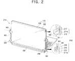
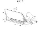
- FIGS. 2 and 3are rear perspective views of the portable computer of FIG. 1 ;
- FIG. 4is a partially exploded perspective view of a display part in the portable computer according to an embodiment of the present invention.
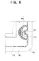
- FIGS. 5 through 7are sectional views illustrating operations of a locking unit in the portable computer according to an embodiment of the present invention.
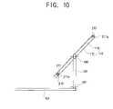
- FIGS. 8 through 11are side views illustrating tilts of the display part in the portable computer according to an embodiment of the present invention.
- FIGS. 12 through 14are exploded perspective views of the display part and a link in the portable computer according to an embodiment of the present invention.
- a portable computercomprises a main body 101 mounted with a plurality of hardware components; a display part 110 for displaying a picture based on a video signal received from the main body 101 ; a pair of links 120 each having a first end hingedly connected to the main body 101 and a second end hingedly connected to the display part 110 (see FIG.
- a display hingeprovided between the first end of each link 120 and the display part 110 and pivotally supporting the display part 110 to allow the display part 110 to tilt relative to the pair of links 120 ; a main hinge provided between the second end of each link 120 and the main body 101 and pivotally supporting the pair of links 120 to allow the pair of links 120 to pivot relative to the main body 101 ; and a locking unit 200 provided in the link 120 and the display part 110 to lock and release the tilt of the display part 110 relative to the link member 120 .
- the portable computerfurther comprises a coupler 180 coupled to the main hinge and adapted to rotate relative to the main body 101 integrally with the links 120 , wherein a rotating axis of the coupler 180 is aligned with a pivoting axis of the link 120 .
- the main body 101comprises a main board (not shown) mounted with a central processing unit (CPU), a graphic chip, etc. thereinside, and an input unit such as a keyboard 103 , a touch pad 104 , etc. thereoutside.
- the main body 101is electrically connected to the display part 110 by a cable 107 and transmits/receives a predetermined signal to/from the display part 110 through the cable 107 .
- the cable 107comprises a first cable through which a digital signal and a power signal are transmitted, and a second cable through which an antenna signal and a switch signal are transmitted.
- the holding partcomprises at least one magnet 190 provided on an upper surface of the main body 101 , and attaching parts 191 and 193 provided on at least one of a front cover 112 and a rear cover 113 of the display part 110 and to which the magnets 190 are attached magnetically.
- the holding partmay comprise a hook (not shown) provided in at least one of the main body 101 and the display part 110 , and a hook holder (not shown) provided in the other one of the main body 101 and the display part 110 and releasably engaged with the hook.
- a pair of magnets 190are provided on the upper surface of the main body 101 at left and right sides.
- a pair of attaching parts 191 and 193are preferably provided on the front cover 112 and rear cover 113 of the display part 110 respectively, so that the magnets 190 can magnetically attach to the attaching parts 191 and 193 .
- the attaching parts 191 and 193are preferably made of a magnetizable material to be attached to the magnet 190 .
- the display part 110utilizes a touch-screen technology, so that the display part 110 permit tablet operation with a stylus pen.
- the display part 110comprises a liquid crystal display (LCD) panel 111 for displaying a picture based on the video signal received from the main body 101 , and the front and rear covers 112 and 113 connected to each other across the LCD panel 111 and supporting the LCD panel 111 at front and rear sides.
- LCDliquid crystal display
- the front cover 112is provided with a first attaching part 191 for attachment to the magnet 190 of the main body 101 at a closed position allowing the front cover 112 to be in contact with the upper surface of the main body 101 .
- the rear cover 113is provided with a second attaching part 193 to be attached to the magnet 190 of the main body 101 at a tablet position allowing the rear cover 113 to be in contact with the upper surface of the main body 101 .
- the coupler 180is aligned with a second hinge axis 197 (to be described later), and couples the pair of links 120 to each other. That is, the coupler 180 supports the pair of links 120 to be pivoted relative to the main body 101 at the same time when the display part 110 tilts relative to the main body 101 . Further, the coupler 180 is placed in a rear upper part of the main body 101 , so that the portable computer can have a slim structure.
- the coupler 180is preferably shaped like a pipe having a circular section to be resistant to torsion. However, the coupler 180 may have a polygonal section such as a rectangular section.
- each link 120comprises an outer cover 130 forming an outer appearance, and an inner cover 140 coupled to the outer cover 130 to form a cable accommodating space.
- the outer cover 130has a first end 131 being bent outward, and a second end 132 being bent inward. Further, the outer cover 130 is provided with thereinside a plurality of bosses 133 to be fastened with coupling holes 146 of the inner cover 140 by first screws 134 .
- the inner cover 140has a first end 141 being bent outward corresponding to the first end 131 of the outer cover 130 , and a second end 142 being bent inward corresponding to the second end 132 of the outer cover 130 . Further, the first end 141 of the inner cover 140 is formed with a first hinge hole 144 to which a first shaft 151 of the first shaft member 150 is rotatably inserted. Further, the second end 142 of the inner cover 140 is formed with an extended part 143 having a second hinge hole 145 to which a second hinge shaft 171 of a second shaft member 170 is rotatably inserted. Further, the inner cover 140 is formed with the plurality of coupling holes 146 corresponding to the plurality of bosses 133 of the outer cover 130 and fastened with the bosses 133 by the first screws 134 .
- the display hingeis provided between the display part 110 and the link 120 and allows the display part 110 to tilt relative to the link 120 . Further, the display hinge comprises the first hinge hole 144 of the inner cover 40 , the first shaft member 150 having the first shaft 151 to be rotatably inserted in the first hinge hole 144 , and a first shaft supporting bracket 160 connected to the rear cover 113 and supporting the first shaft 151 rotatably inserted in the first hinge hole 144 .
- the first shaft member 150comprises a first shaft supporter 155 disposed between the first end 141 of the inner cover 140 and the first end 131 of the outer cover 130 , the first shaft 151 being rotatably connected to the first shaft supporter 155 and protruding toward the rear cover 113 , a first cable through hole 152 formed in the first shaft member 150 along a lengthwise direction of the first shaft 151 to allow the cable 107 to pass therethrough, and a pair of connection part 153 extended from opposite sides of the first shaft supporter 155 and connected to the first end 141 of the inner cover 140 and the first end 131 of the outer cover 130 by screws.
- the first shaft 151has a first end rotatably and frictionally connected to the first shaft supporter 155 , and a second end which is forcibly fitted in a first shaft hole 161 of the first shaft supporting bracket 160 connected to the display part 110 and rotates integrally with the first shaft supporting bracket 160 . That is, the first end of the first shaft 151 is rotatably and frictionally fitted to the first shaft supporter 155 , and therefore a force large enough to overcome a predetermined friction is needed to tilt the display part 110 relative to the link 120 . Preferably, such predetermined friction is large enough to prevent the display part 110 from tilting relative to the link 120 by the weight of the display part 110 and to allow a user to easily tilt the display part 110 relative to the link 120 . Thus, the display part 110 can tilt about a first hinge axis 196 (see FIG. 10 ) formed by the first shaft 151 .
- the first shaft supporting bracket 160comprises the first shaft hole 161 to which the second end of the first shaft 151 is forcibly and integrally fitted, and a pair of wings 162 protruding from opposite sides of the first shaft supporting bracket 160 .
- Each. wing 162is formed with a screw through hole 164 to be fastened to a fastening part 115 of the rear cover 113 by a second screw 165 .
- the main hingeis provided between the link 120 and the main body 101 and allows the link 120 to pivot relative to the main body 101 . Further, the main hinge comprises the second hinge hole 145 formed in the extended part 143 of the inner cover 140 , and the second shaft member 170 provided between an end of the coupler 180 and the extended part 143 of the inner cover 140 .
- the second shaft member 170comprises the second shaft 171 forcibly fitted in the second hinge hole 145 of the inner cover 140 and rotating integrally with the inner cover 140 , a second shaft supporter 179 rotatably and frictionally supporting the second shaft 171 , and a second shaft coupling part 174 extended from the second shaft 171 toward the coupler 180 and integrally coupled to the coupler 180 .
- the second shaft supporter 179has a first end rotatably connected to the second shaft 171 , and a second end connected to the main body by a screw or the like.
- the second shaft 171is forcibly fitted in the second hinge hole 145 formed in the extended part 143 of the inner cover 140 .
- the second shaft 171is rotatably and frictionally connected to the second shaft supporter 179 . That is, the second shaft 171 is rotatably and frictionally fitted to the second shaft supporter 179 . Therefore a force large enough to overcome a predetermined friction is needed to pivot the link 120 relative to the main body 101 .
- a predetermined frictionis used for a purpose similar to the friction between the first shaft 151 and the first shaft supporter 155 , and therefore a detailed description thereof will be omitted.
- the second shaft 171is formed with a second cable through hole 172 communicating with the cable accommodating space between the inner cover 140 and the outer cover 130 .
- the cable 107passes through the first cable through hole 172 of the first shaft 151 , the cable accommodating space of the link 120 , the second cable through hole 172 of the second shaft 171 in sequence.
- the second shaft 171is forcibly and integrally fitted in the second hinge hole 145 , and rotatably and frictionally inserted in the second shaft supporter 179 , thereby allowing the display part 110 to tilt about the second shaft 171 .
- the display part 110can tilt about the second hinge axis 197 formed by the second shaft 171 .
- the second hinge axis 197is in parallel with and spaced from the first hinge axis 196 , and is aligned with the coupler 180 . That is, when the display part 110 is tilted about the second hinge axis 197 of the second shaft 171 of the main hinge, the coupler 180 is aligned with the second hinge axis 197 .
- the coupler 180is coupled to the second shaft coupling part 174 extended from the second shaft 171 and rotates integrally with the second shaft 171 .
- the second shaft coupling part 174extends from the second shaft 171 toward the coupler 180 , and is coupled to the end of the coupler 180 shaped like a pipe.
- the second shaft coupling parts 174are forcibly fitted to the opposite ends of the coupler 180 so as to rotate integrally with the second shaft 171 .
- the second shaft coupling part 174may be coupled to the coupler 180 by a screw or the like.
- a bypassing opening 173being cut to communicate with the second cable through hole 172 of the second shaft 171 .
- the cable 107 passing through the second cable through hole 172is connected to the main body 101 through the bypassing opening 173 .
- the locking unit 200comprises a locking projection 201 protruding from one of the link 120 and the display part 110 toward the other one, and a projection holder 210 provided in the other one and elastically locked to and released from the locking projection 201 .
- the locking projection 201is provided in the pair of links 120 , respectively. However, the locking projection 201 may be provided in at least one of the pair of links 120 . Preferably, the locking projection 201 protrudes from the inner cover 140 of the link 120 toward the display part 110 . More preferably, the locking projection 201 is placed adjacent to the second end of the link 120 connected to the main hinge. According to an embodiment of the present invention, the locking projection 201 has a rectangular shape, but may have a polygonal shape, an arc shape, etc.
- the projection holder 210is placed in a lateral side of the display part 110 , corresponding to the locking projection 201 .
- the projection holder 210comprises a projection accommodating part 211 formed in the lateral side of the display part 110 to allow the display part 110 tilted relative to the link 120 to accommodate the locking projection 201 , and a holding projection 213 elastically retracted in the projection accommodating part 211 by contacting the locking projection 201 .
- the projection holder 210comprises a spring 215 elastically pushing the holding projection 213 toward the outside of the display part 110 .
- the projection accommodating part 211comprises an opening 212 opened in the back of the display part 110 , and an elastic member 217 facing opposite the opening 212 and contacting the locking projection 201 past the holding projection 213 so as to prevent noise from coming out. Further, the projection accommodating part 211 is provided symmetrically with respect to the first hinge axis 196 , forming a pair. That is, referring to FIG. 2 , the projection accommodating part 211 comprises a pair of first projection accommodating parts 211 a located in upper opposite sides of the display part 110 , and a pair of second projection accommodating parts 211 b located in lower opposite sides of the display part 110 .
- the projection accommodating part 211is provided with a holding projection through part 218 through which a first part 213 a of the holding projection 213 is exposed toward the locking projection 201 .
- the projection accommodating part 211is preferably provided in the rear cover 113 of the display part 110 to accommodate the locking projection 201 , but may be provided in the front cover 112 .
- the first end 213 a of the holding projection 213is smaller than the holding projection through part 218 so as to pass through the holding projection through part 218 , and has a wedge-shape to easily contact the locking projection 201 .
- a second end 213 b of the holding projection 213is larger than the holding projection through part 218 so as to not pass through the holding projection through part 218 , and has a spring contact part 214 grooved to easily contact the spring 215 .
- the spring 215is coupled to the display part 110 , being in contact with the second end 213 b of the holding projection 213 and elastically pushing the holding projection 213 outward from the display part 110 .
- the spring 215is coupled to the rear cover 113 of the display part 110 and contacts the spring contact part 214 , and the rear cover 113 is provided with a spring supporter 116 to support opposite ends of the spring 215 .
- the spring 215is preferably a coil spring, but may be made of an elastic material such as a flat spring, a rubber material, etc.
- the holding projection 213 and the spring 215are provided in only the second projection accommodating parts 211 b , but may be provided in only the first projection accommodating part 211 a or both the first and second projection accommodating parts 211 a and 211 b.
- the elastic member 217is preferably provided in both the first and second projection accommodating parts 211 a and 211 b . Further, the elastic member 217 is preferably placed in the projection accommodating part 211 , facing opposite the opening 212 . Here, the elastic member 217 contacts the locking projection 201 elastically past the holding projection 213 , and prevents the locking projection 201 from moving.
- the elastic member 217is made of a rubber material.
- the elastic member 217is provided with an insertion part 217 a to be elastically inserted and connected into an insertion hole 219 of the projection accommodating part 211 facing opposite to the opening 212 .
- the elastic member 217may be a spring which contacts the locking projection 201 and prevent the noise from coming out.
- the display part 110 and the link 120are rotated with respect to the second hinge axis 197 , and changed from the closed position (refer to FIG. 8 ) in which the front cover 112 is in contact with the upper surface of the main body 101 to the opened position (refer to FIG. 9 ) in which the display part 110 is opened relative to the main body 101 .
- the locking projection 201 of the link 120is accommodated in the second projection accommodating part 211 b of the projection holder 210 provided in the display part 110 and rotates integrally with the display part 110 . That is, when the display part 110 is upwardly pushed and tilted from the closed position (refer to FIG. 8 ) to the opened position (refer to FIG.
- the locking projection 201is in contact with the holding projection 213 and the elastic member 217 of the second projection accommodating part 211 b , so that the display part 110 does not rotate relative to the link 120 . Therefore, even if a user pushes only the display part 110 downward, the link 120 rotates integrally with the display part 110 , so that it is convenient for the user. Further, even if the user pushes only the display part 110 , the display part 110 does not freely rotate relative to the link 120 , thereby preventing the display part 110 from an unintentional collision with the main body 101 .
- the display part 110can be tilted further from the opened position shown in FIG. 9 , that is, a lower part of the display part 110 can be tilted forward relative to the link 120 (refer to FIG. 10 ).
- a userhas to push the display part 110 with enough force to allow the locking projection 201 accommodated in the second projection accommodating part 211 b to be elastically pushed by the holding projection 213 .
- the locking projection 201moves from a locked position (refer to FIG. 5 ), in which the locking projection 201 is accommodated in the second projection accommodating part 211 b and locked by the holding projection 213 , to a released position (refer to FIG. 7 ), in which the locking projection 201 is released from the second projection accommodating part 211 b , via a pushing position (refer to FIG. 6 ), in which the locking projection 201 is elastically pushing the holding projection 213 .
- the display part 110can be tilted further relative to the link 120 from the position shown in FIG. 10 until the locking projection 201 is accommodated in the first projection accommodating part 211 a . Then, the display part 110 and the link 120 can be integrally tilted relative to the main body 101 and changed to the tablet position (refer to FIG. 11 ) in which the rear cover 113 of the display part 110 is in contact with the upper surface of the main body 101 . At this time, the locking projection 201 of the link 120 is accommodated in and pivoted integrally with the first projection accommodating part 211 a of the display part 110 . That is, when the display part 110 is downwardly pushed and tilted to the tablet position (refer to FIG.
- the locking projection 201is in contact with the elastic member 217 of the first projection accommodating part 211 a , so that the display part 110 does not rotate relative to the link 120 . Therefore, even if a user pushes only the display part 110 downward, the link 120 rotates integrally with the display part 110 , so that it is convenient for the user. Further, even if the user pushes only the display part 110 , the display part 110 does not freely rotate relative to the link 120 , thereby preventing the display part 110 from an unwanted collision with the main body 101 .
- the portable computerfurther comprises the coupler 180 coupled to the main hinge and rotating relative to the main body 101 integrally with the links 120 , wherein the rotating axis of the coupler 180 is aligned with the pivoting axis of the link 120 . Therefore, the coupler 180 prevents the torsion from being generated when the pair of second shaft members 170 may be individually rotated, so that the display part 110 is stably tilted and prevented from being a problem.
- the display part 110is tilted relative to the main body 101 , if the pair of second shaft members 170 are not simultaneously rotated, the display part 110 is distorted and is not smoothly and stably tilted and the LCD panel 111 may be distorted, thereby causing a problem in the display part 110 .
- the first shaft 151is forcibly fitted in a first shaft hole 161 of the first shaft supporting bracket 160 and rotates integrally with the first shaft supporting bracket 160
- the second shaft 171is forcibly fitted in the second hinge hole 145 formed in the extended part 143 of the inner cover 140 and rotates integrally with the inner cover 140
- the first shaft 151 and the second shaft 171may have noncircular sections and be integrally fitted to the first shaft hole 161 and the second hinge hole 145 , respectively.
- the illustrated embodiments of the present inventionprovide a portable computer having an improved structure for convenience and stability when a display part is tilted.
- the illustrated embodiments of the present inventionprovide a portable computer comprising a coupler coupled to a main hinge and aligned with an axis of the main hinge, so that the display part is stably tilted and prevented from torsion and being a problem.
Landscapes
- Engineering & Computer Science (AREA)
- Theoretical Computer Science (AREA)
- Computer Hardware Design (AREA)
- Physics & Mathematics (AREA)
- Human Computer Interaction (AREA)
- General Engineering & Computer Science (AREA)
- General Physics & Mathematics (AREA)
- Computer Networks & Wireless Communication (AREA)
- Mathematical Physics (AREA)
- Pivots And Pivotal Connections (AREA)
- Devices For Indicating Variable Information By Combining Individual Elements (AREA)
- Casings For Electric Apparatus (AREA)
Abstract
Description
Claims (14)
Applications Claiming Priority (2)
| Application Number | Priority Date | Filing Date | Title |
|---|---|---|---|
| KR2003-89206 | 2003-12-10 | ||
| KR10-2003-0089206AKR100534125B1 (en) | 2003-12-10 | 2003-12-10 | Portable computer |
Publications (2)
| Publication Number | Publication Date |
|---|---|
| US20050128695A1 US20050128695A1 (en) | 2005-06-16 |
| US7283355B2true US7283355B2 (en) | 2007-10-16 |
Family
ID=34651319
Family Applications (1)
| Application Number | Title | Priority Date | Filing Date |
|---|---|---|---|
| US10/994,414Expired - Fee RelatedUS7283355B2 (en) | 2003-12-10 | 2004-11-23 | Portable computer |
Country Status (4)
| Country | Link |
|---|---|
| US (1) | US7283355B2 (en) |
| JP (1) | JP2005174348A (en) |
| KR (1) | KR100534125B1 (en) |
| CN (1) | CN1303492C (en) |
Cited By (35)
| Publication number | Priority date | Publication date | Assignee | Title |
|---|---|---|---|---|
| US20060154732A1 (en)* | 2005-01-10 | 2006-07-13 | Tastad Gregory J | Releasable display mounting system and method |
| US20070057127A1 (en)* | 2005-09-15 | 2007-03-15 | Dell Products L.P. | Method and apparatus for controlling display rotation on an information handling system |
| US20070058331A1 (en)* | 2005-09-15 | 2007-03-15 | Dell Products L.P. | Method and apparatus for supporting a display on a chassis |
| US20070121303A1 (en)* | 2005-11-30 | 2007-05-31 | High Tech Computer Corp. | Multi-Configuration Portable Electronic Device and Guiding Module Thereof |
| US20080024964A1 (en)* | 2006-07-25 | 2008-01-31 | Lev Jeffrey A | Anti-rotation mechanism for an electronic device |
| US20090103261A1 (en)* | 2007-10-23 | 2009-04-23 | Htc Corporation | Electronic device |
| USD611467S1 (en)* | 2009-05-20 | 2010-03-09 | Cheng Uei Precision Industry Co., Ltd. | Notebook computer |
| US20100134964A1 (en)* | 2004-03-08 | 2010-06-03 | Originatic Llc | Electronic Device |
| USD621826S1 (en)* | 2009-09-14 | 2010-08-17 | Hon Hai Precision Industry Co., Ltd. | Portable electronic device |
| USD621829S1 (en)* | 2009-11-24 | 2010-08-17 | Hon Hai Precision Industry Co., Ltd. | Portable electronic device |
| USD621827S1 (en)* | 2009-10-22 | 2010-08-17 | Hon Hai Precision Industry Co., Ltd. | Portable electronic device |
| USD621828S1 (en)* | 2009-11-27 | 2010-08-17 | Hon Hai Precision Industry Co., Ltd. | Portable electronic device |
| USD626547S1 (en)* | 2009-12-31 | 2010-11-02 | Hon Hai Precision Industry Co., Ltd. | Notebook computer |
| US20110012858A1 (en)* | 2008-06-12 | 2011-01-20 | Canova Technologies Limited | Dual screen display system |
| US20110043975A1 (en)* | 2009-08-19 | 2011-02-24 | Inventec Corporation | Portable electronic device structure |
| US20110075340A1 (en)* | 2008-06-18 | 2011-03-31 | Biao Qin | Portable Electronic Computer |
| US20110177850A1 (en)* | 2010-01-15 | 2011-07-21 | Research In Motion Limited | Mobile communication device having overlapping first and second body members |
| US20120008277A1 (en)* | 2010-07-08 | 2012-01-12 | Dell Products L.P. | IHS Securing System |
| US20120194977A1 (en)* | 2011-01-31 | 2012-08-02 | Quanta Computer Inc. | Portable electronic device |
| US20130036846A1 (en)* | 2011-08-10 | 2013-02-14 | Research In Motion Limited | Mobile electronic device having member rotatable between first and second positions |
| US20130128443A1 (en)* | 2011-11-18 | 2013-05-23 | Wistron Corporation | Portable Computer |
| US20130220043A1 (en)* | 2012-02-29 | 2013-08-29 | First Dome Corporation | Jacking device |
| US20140043743A1 (en)* | 2012-08-08 | 2014-02-13 | Wistron Corporation | Portable electronic device |
| US20140118929A1 (en)* | 2012-10-31 | 2014-05-01 | Quanta Computer Inc. | Portable electrical device |
| US20140301028A1 (en)* | 2013-04-09 | 2014-10-09 | Acer Incorporated | Electronic equipment |
| US20140321038A1 (en)* | 2013-04-29 | 2014-10-30 | Samsung Electronics Co., Ltd | Convertible computing apparatus |
| USD732523S1 (en)* | 2012-07-13 | 2015-06-23 | Google Inc. | Portable computer |
| US9128664B1 (en) | 2012-01-18 | 2015-09-08 | Google Inc. | Invertible clamshell notebook computer |
| US9176525B2 (en) | 2012-01-31 | 2015-11-03 | Kabushiki Kaisha Toshiba | Electronic apparatus |
| USD780174S1 (en)* | 2015-02-23 | 2017-02-28 | Lg Electronics Inc. | Tablet computer |
| TWI595350B (en)* | 2015-12-18 | 2017-08-11 | 仁寶電腦工業股份有限公司 | Electronic equipment |
| US10359145B2 (en) | 2015-09-18 | 2019-07-23 | Ubs Business Solutions Ag | Display system |
| US10466749B1 (en)* | 2018-09-26 | 2019-11-05 | Apple Inc. | Peripheral housing for a computing device |
| US11126227B2 (en)* | 2018-09-17 | 2021-09-21 | Compal Electronics, Inc. | Electronic device |
| US11709527B2 (en) | 2020-07-30 | 2023-07-25 | Apple Inc. | Modularized computing and input devices |
Families Citing this family (77)
| Publication number | Priority date | Publication date | Assignee | Title |
|---|---|---|---|---|
| US7277275B2 (en)* | 2003-04-09 | 2007-10-02 | Samsung Electronics Co., Ltd. | Portable computer having adjustable display |
| JP2005107840A (en)* | 2003-09-30 | 2005-04-21 | Toshiba Corp | Electronics |
| KR100630098B1 (en)* | 2004-02-20 | 2006-09-27 | 삼성전자주식회사 | Portable digital communication device |
| US20060044288A1 (en)* | 2004-06-18 | 2006-03-02 | Hiroshi Nakamura | Multi-functional electronic device utilizing a stylus pen |
| US20060254861A1 (en)* | 2005-04-29 | 2006-11-16 | Sprn Licensing Srl | Electronic shopping cart handle |
| USD528541S1 (en)* | 2005-08-04 | 2006-09-19 | Acer, Inc. | Portable computer |
| TWI287719B (en)* | 2005-11-10 | 2007-10-01 | Asustek Comp Inc | Latch device for tablet personal computer |
| USD566117S1 (en)* | 2006-06-02 | 2008-04-08 | Sondyo Computer Co., Ltd. | Audio and light keyboard |
| USD584300S1 (en)* | 2007-03-22 | 2009-01-06 | Fujitsu Limited | Personal computer |
| USD587715S1 (en) | 2007-04-27 | 2009-03-03 | Hewlett-Packard Development Company, L.P. | Dual hinge portable computer |
| US8520377B2 (en)* | 2007-05-01 | 2013-08-27 | Hewlett-Packard Development Company, L.P. | Electronic device adjustable display member |
| CN101377693B (en)* | 2007-08-30 | 2011-03-23 | 英业达股份有限公司 | Electronic device |
| USD584304S1 (en)* | 2007-09-13 | 2009-01-06 | Htc Corporation | Handheld electronic device |
| EP2051485A1 (en)* | 2007-10-15 | 2009-04-22 | Sony Ericsson Mobile Communications AB | Electronic device with a display unit being movable in relation to a base unit |
| US20090231805A1 (en)* | 2008-02-21 | 2009-09-17 | Maria Carmen Schlesener | System and Method for Information Handling System Chassis Impact Bumpers |
| TWD132934S1 (en)* | 2008-03-28 | 2010-01-11 | 富士通股份有限公司 | Personal computer |
| WO2009146042A2 (en) | 2008-03-31 | 2009-12-03 | Terra Soft Solutions Of Colorado, Inc. | Tablet computer |
| US8577957B2 (en)* | 2008-04-01 | 2013-11-05 | Litl Llc | System and method for streamlining user interaction with electronic content |
| US20090322790A1 (en)* | 2008-04-01 | 2009-12-31 | Yves Behar | System and method for streamlining user interaction with electronic content |
| US8612888B2 (en) | 2008-04-01 | 2013-12-17 | Litl, Llc | Method and apparatus for managing digital media content |
| US8624844B2 (en) | 2008-04-01 | 2014-01-07 | Litl Llc | Portable computer with multiple display configurations |
| US9003315B2 (en)* | 2008-04-01 | 2015-04-07 | Litl Llc | System and method for streamlining user interaction with electronic content |
| USD593091S1 (en)* | 2008-05-13 | 2009-05-26 | Yves Behar | Digital display device |
| TWD128407S1 (en)* | 2008-06-20 | 2009-04-21 | 華碩電腦股份有限公司 | Tablet pc |
| TWI332816B (en)* | 2008-07-25 | 2010-11-01 | Htc Corp | Electronic device |
| JP2010268125A (en)* | 2009-05-13 | 2010-11-25 | Panasonic Corp | Portable radio |
| CN101725802A (en)* | 2009-12-25 | 2010-06-09 | 尹志斌 | Rotating supporting device for display screen |
| EP2530913A4 (en)* | 2010-01-28 | 2014-05-21 | Nec Corp | Portable electronic apparatus |
| US8749963B2 (en)* | 2010-03-15 | 2014-06-10 | Over The Sun, Llc | Housing for slate tablet computer |
| CN102236365A (en)* | 2010-04-23 | 2011-11-09 | 鸿富锦精密工业(深圳)有限公司 | Portable electronic device |
| GB201009952D0 (en)* | 2010-05-11 | 2010-07-21 | Hu Do Ltd | Hinge development |
| US8264599B2 (en)* | 2010-05-17 | 2012-09-11 | Sunrex Technology Corp. | Laptop with pivotal camera and micro-projector and screen as a replacement of display |
| USD646270S1 (en)* | 2010-11-18 | 2011-10-04 | Dell Products L.P. | Portable information handling system |
| US8630089B2 (en)* | 2011-01-21 | 2014-01-14 | Blackberry Limited | Resilient swivel coupling mechanism |
| TWI459886B (en)* | 2011-03-11 | 2014-11-01 | Quanta Comp Inc | Portable electrical device |
| TW201306583A (en)* | 2011-07-25 | 2013-02-01 | Compal Electronics Inc | Supporting assembly for assembled detachable electronic device and assembled detachable electronic device having the same |
| US20130088824A1 (en)* | 2011-10-06 | 2013-04-11 | International Business Machines Corporation | Portable computer with highly adjustable ergonomic display screen |
| JP5214812B1 (en)* | 2012-01-10 | 2013-06-19 | 株式会社東芝 | Electronics |
| JP2013161255A (en)* | 2012-02-03 | 2013-08-19 | Sony Corp | Information terminal device and information processing method |
| US9179567B2 (en)* | 2012-05-23 | 2015-11-03 | Asustek Computer Inc. | Electronic device |
| KR101417974B1 (en)* | 2012-07-13 | 2014-07-09 | 강원대학교산학협력단 | Folding workbench for implementation of virtual reality |
| TWI480720B (en) | 2012-07-24 | 2015-04-11 | Quanta Comp Inc | Portable electrical device |
| KR101991940B1 (en)* | 2012-08-08 | 2019-06-24 | 삼성전자주식회사 | Portable electronic apparatus |
| CN104519789A (en)* | 2012-08-09 | 2015-04-15 | 皇家飞利浦有限公司 | Device for home monitoring of haematological parameters of patients |
| JP5935594B2 (en)* | 2012-08-24 | 2016-06-15 | ソニー株式会社 | Information processing device |
| US9715251B2 (en)* | 2012-08-28 | 2017-07-25 | Samsung Electronics Co., Ltd. | Portable device |
| USD708177S1 (en)* | 2012-09-24 | 2014-07-01 | Panasonic Corporation | Portable computer |
| US8915477B2 (en)* | 2012-10-04 | 2014-12-23 | First Dome Corporation | Auxiliary support device for flip touch screen |
| USD691603S1 (en)* | 2012-10-17 | 2013-10-15 | Dell Products L.P. | Convertible information handling system |
| USD718302S1 (en)* | 2012-10-25 | 2014-11-25 | Lg Electronics Inc. | Convertible computer |
| CN104756037B (en) | 2012-11-09 | 2019-03-12 | 惠普发展公司,有限责任合伙企业 | Magnets at display assembly and base |
| JP5978942B2 (en)* | 2012-11-16 | 2016-08-24 | ブラザー工業株式会社 | Image reading device |
| CN103867559B (en)* | 2012-12-14 | 2016-06-29 | 宏碁股份有限公司 | connection mechanism |
| JP6060753B2 (en)* | 2013-03-18 | 2017-01-18 | 富士通株式会社 | Electronic equipment |
| CN103135694A (en)* | 2013-03-26 | 2013-06-05 | 杨笑天 | Flip-type laptop |
| JP2014214783A (en)* | 2013-04-24 | 2014-11-17 | 株式会社ナチュラレーザ・ワン | Hinge device with latch mechanism, and information appliance |
| WO2015016816A1 (en)* | 2013-07-29 | 2015-02-05 | Hewlett-Packard Development Company, L.P. | Adjustable display housing assembly |
| US10317937B2 (en) | 2014-05-28 | 2019-06-11 | Hewlett-Packard Development Company, L.P. | Computing device with a rotatable display housing |
| CN105334910B (en)* | 2014-06-24 | 2019-03-29 | 联想(北京)有限公司 | A kind of magnetic force control method and device |
| WO2015199714A1 (en)* | 2014-06-27 | 2015-12-30 | Hewlett-Packard Development Company, L.P. | Computing device with a rotatable display member |
| US10310564B2 (en) | 2014-06-30 | 2019-06-04 | Hewlett-Packard Development Company, L.P. | Linking mechanism for a computing device with a rotatable display member |
| WO2016014047A1 (en)* | 2014-07-23 | 2016-01-28 | Apple Inc. | Adaptive processes for improving integrity of surfaces |
| US10649497B2 (en) | 2014-07-23 | 2020-05-12 | Apple Inc. | Adaptive processes for improving integrity of surfaces |
| US9983632B2 (en)* | 2015-10-12 | 2018-05-29 | Google Llc | Cover to protect keyboard and bottom of laptop computer |
| US10172248B1 (en) | 2016-04-14 | 2019-01-01 | Microsoft Technology Licensing, Llc | Device with a rotatable display |
| US10159158B2 (en) | 2016-04-14 | 2018-12-18 | Microsoft Technology Licensing, Llc | Device with a rotatable display |
| US9936593B2 (en) | 2016-04-14 | 2018-04-03 | Microsoft Technology Licensing, Llc | Device with a rotatable display |
| US10345851B2 (en) | 2016-04-14 | 2019-07-09 | Microsoft Technology Licensing, Llc | Device with a rotatable display |
| US10996710B2 (en) | 2016-04-14 | 2021-05-04 | Microsoft Technology Licensing, Llc | Device with a rotatable display |
| US10999944B2 (en) | 2016-04-26 | 2021-05-04 | Microsoft Technology Licensing, Llc | Structural device cover |
| WO2017201190A1 (en) | 2016-05-18 | 2017-11-23 | Shanghai Yanfeng Jinqiao Automotive Trim Systems Co. Ltd | Console assembly for vehicle interior |
| US9946309B2 (en) | 2016-06-10 | 2018-04-17 | Microsoft Technology Licensing, Llc | Device wiring |
| CN107526391B (en)* | 2016-06-21 | 2020-05-08 | 鸿富锦精密电子(重庆)有限公司 | Display device |
| DE102016118597A1 (en)* | 2016-09-30 | 2018-04-05 | Ma Lighting Technology Gmbh | Lighting desk with adjustable screen housing |
| US11572723B2 (en) | 2019-02-27 | 2023-02-07 | Shanghai Yanfeng Jinqiao Automotive Triim Systems Co. Ltd. | Vehicle interior component |
| CN113454565B (en) | 2019-04-25 | 2025-01-07 | 惠普发展公司,有限责任合伙企业 | Housing with electrical contacts |
| TWD218694S (en)* | 2021-10-29 | 2022-05-01 | 宏碁股份有限公司 | Notebook computer |
Citations (13)
| Publication number | Priority date | Publication date | Assignee | Title |
|---|---|---|---|---|
| US5255214A (en)* | 1992-09-11 | 1993-10-19 | Ma Hsi Kuang | Portable computer with a level and angular position adjustable LCD assembly |
| US5267123A (en)* | 1989-11-10 | 1993-11-30 | Eo Europe Limited | Case for portable computer having display accessible when lid is closed over the keyboard |
| JPH07295680A (en) | 1994-04-26 | 1995-11-10 | Nec Corp | Tablet integrated type personal computer |
| US5900848A (en)* | 1996-05-17 | 1999-05-04 | Sharp Kabushiki Kaisha | Information processing apparatus |
| US6266236B1 (en)* | 1997-08-27 | 2001-07-24 | Vadem | Apparatus and method for connecting and articulating display in a portable computer having multiple display orientations |
| KR100297746B1 (en) | 1997-12-26 | 2001-08-07 | 윤종용 | Portable computer |
| US6384811B1 (en)* | 1999-06-08 | 2002-05-07 | Compal Electronics, Inc. | Portable computer having a display module moveable among closed, keyboard typing and image viewing positions |
| KR200316620Y1 (en) | 2003-03-12 | 2003-06-18 | 김성균 | The structure of Tablet note PC |
| KR200317129Y1 (en) | 2003-03-20 | 2003-06-25 | 김성균 | The structure of Tablet notebook PC that turn easily. |
| US6665175B1 (en)* | 2002-02-04 | 2003-12-16 | Deboer Carrie | Computer having a monitor that has multiple degrees of freedom with respect to the base of the computer |
| US20050078444A1 (en)* | 2003-10-09 | 2005-04-14 | Seung-Man Hong | Portable computer |
| US20050083644A1 (en)* | 2003-10-16 | 2005-04-21 | Young-Shin Song | Portable computer |
| US20050105263A1 (en)* | 2003-11-18 | 2005-05-19 | Toshiyuki Tanaka | Tablet interlocking mechanism |
Family Cites Families (6)
| Publication number | Priority date | Publication date | Assignee | Title |
|---|---|---|---|---|
| JP2500458Y2 (en)* | 1986-06-30 | 1996-06-05 | 株式会社東芝 | Portable electronic devices |
| JP3103157B2 (en)* | 1991-10-14 | 2000-10-23 | 株式会社東芝 | Portable electronic devices |
| US5237488A (en)* | 1992-05-11 | 1993-08-17 | Virginia Polytechnic Institute & State University | Portable computer with display unit connected to system unit through conducting hinge |
| US5666694A (en)* | 1995-09-28 | 1997-09-16 | Hewlett-Packard Company | Hinge arrangement |
| US5805415A (en)* | 1996-10-03 | 1998-09-08 | Hewlett-Packard Company | Detachable flat panel computer display and support |
| KR100284300B1 (en)* | 1998-10-16 | 2001-03-02 | 윤종용 | Portable computer |
- 2003
- 2003-12-10KRKR10-2003-0089206Apatent/KR100534125B1/ennot_activeExpired - Fee Related
- 2004
- 2004-11-10CNCNB2004100904765Apatent/CN1303492C/ennot_activeExpired - Fee Related
- 2004-11-23USUS10/994,414patent/US7283355B2/ennot_activeExpired - Fee Related
- 2004-12-10JPJP2004359168Apatent/JP2005174348A/enactivePending
Patent Citations (13)
| Publication number | Priority date | Publication date | Assignee | Title |
|---|---|---|---|---|
| US5267123A (en)* | 1989-11-10 | 1993-11-30 | Eo Europe Limited | Case for portable computer having display accessible when lid is closed over the keyboard |
| US5255214A (en)* | 1992-09-11 | 1993-10-19 | Ma Hsi Kuang | Portable computer with a level and angular position adjustable LCD assembly |
| JPH07295680A (en) | 1994-04-26 | 1995-11-10 | Nec Corp | Tablet integrated type personal computer |
| US5900848A (en)* | 1996-05-17 | 1999-05-04 | Sharp Kabushiki Kaisha | Information processing apparatus |
| US6266236B1 (en)* | 1997-08-27 | 2001-07-24 | Vadem | Apparatus and method for connecting and articulating display in a portable computer having multiple display orientations |
| KR100297746B1 (en) | 1997-12-26 | 2001-08-07 | 윤종용 | Portable computer |
| US6384811B1 (en)* | 1999-06-08 | 2002-05-07 | Compal Electronics, Inc. | Portable computer having a display module moveable among closed, keyboard typing and image viewing positions |
| US6665175B1 (en)* | 2002-02-04 | 2003-12-16 | Deboer Carrie | Computer having a monitor that has multiple degrees of freedom with respect to the base of the computer |
| KR200316620Y1 (en) | 2003-03-12 | 2003-06-18 | 김성균 | The structure of Tablet note PC |
| KR200317129Y1 (en) | 2003-03-20 | 2003-06-25 | 김성균 | The structure of Tablet notebook PC that turn easily. |
| US20050078444A1 (en)* | 2003-10-09 | 2005-04-14 | Seung-Man Hong | Portable computer |
| US20050083644A1 (en)* | 2003-10-16 | 2005-04-21 | Young-Shin Song | Portable computer |
| US20050105263A1 (en)* | 2003-11-18 | 2005-05-19 | Toshiyuki Tanaka | Tablet interlocking mechanism |
Cited By (60)
| Publication number | Priority date | Publication date | Assignee | Title |
|---|---|---|---|---|
| US20100134964A1 (en)* | 2004-03-08 | 2010-06-03 | Originatic Llc | Electronic Device |
| US7540806B2 (en)* | 2005-01-10 | 2009-06-02 | Wms Gaming Inc. | Releasable display mounting system and method |
| US20060154732A1 (en)* | 2005-01-10 | 2006-07-13 | Tastad Gregory J | Releasable display mounting system and method |
| US20070057127A1 (en)* | 2005-09-15 | 2007-03-15 | Dell Products L.P. | Method and apparatus for controlling display rotation on an information handling system |
| US20070058331A1 (en)* | 2005-09-15 | 2007-03-15 | Dell Products L.P. | Method and apparatus for supporting a display on a chassis |
| US7787242B2 (en)* | 2005-09-15 | 2010-08-31 | Dell Products L.P. | Method and apparatus for supporting a display on a chassis |
| US7566033B2 (en)* | 2005-09-15 | 2009-07-28 | Dell Products L.P. | Method and apparatus for controlling display rotation on an information handling system |
| US7595980B2 (en)* | 2005-11-30 | 2009-09-29 | Htc Corporation | Multi-configuration portable electronic device and guiding module thereof |
| US20070121303A1 (en)* | 2005-11-30 | 2007-05-31 | High Tech Computer Corp. | Multi-Configuration Portable Electronic Device and Guiding Module Thereof |
| US7515405B2 (en)* | 2006-07-25 | 2009-04-07 | Hewlett-Packard Development Company, L.P. | Anti-rotation mechanism for an electronic device |
| US20080024964A1 (en)* | 2006-07-25 | 2008-01-31 | Lev Jeffrey A | Anti-rotation mechanism for an electronic device |
| US20090103261A1 (en)* | 2007-10-23 | 2009-04-23 | Htc Corporation | Electronic device |
| US8223489B2 (en)* | 2007-10-23 | 2012-07-17 | Htc Corporation | Electronic device |
| US20110012858A1 (en)* | 2008-06-12 | 2011-01-20 | Canova Technologies Limited | Dual screen display system |
| US20110075340A1 (en)* | 2008-06-18 | 2011-03-31 | Biao Qin | Portable Electronic Computer |
| US9841794B2 (en)* | 2008-06-18 | 2017-12-12 | Shenzhen Qin Bo Core Technology Development Co., Ltd. | Portable electronic computer |
| USD611467S1 (en)* | 2009-05-20 | 2010-03-09 | Cheng Uei Precision Industry Co., Ltd. | Notebook computer |
| US20110043975A1 (en)* | 2009-08-19 | 2011-02-24 | Inventec Corporation | Portable electronic device structure |
| US7903400B1 (en)* | 2009-08-19 | 2011-03-08 | Inventec Corporation | Portable electronic device structure |
| USD621826S1 (en)* | 2009-09-14 | 2010-08-17 | Hon Hai Precision Industry Co., Ltd. | Portable electronic device |
| USD621827S1 (en)* | 2009-10-22 | 2010-08-17 | Hon Hai Precision Industry Co., Ltd. | Portable electronic device |
| USD621829S1 (en)* | 2009-11-24 | 2010-08-17 | Hon Hai Precision Industry Co., Ltd. | Portable electronic device |
| USD621828S1 (en)* | 2009-11-27 | 2010-08-17 | Hon Hai Precision Industry Co., Ltd. | Portable electronic device |
| USD626547S1 (en)* | 2009-12-31 | 2010-11-02 | Hon Hai Precision Industry Co., Ltd. | Notebook computer |
| US20110177850A1 (en)* | 2010-01-15 | 2011-07-21 | Research In Motion Limited | Mobile communication device having overlapping first and second body members |
| US8843183B2 (en) | 2010-01-15 | 2014-09-23 | Blackberry Limited | Mobile communication device having overlapping first and second body members |
| US20120008277A1 (en)* | 2010-07-08 | 2012-01-12 | Dell Products L.P. | IHS Securing System |
| US8432688B2 (en)* | 2010-07-08 | 2013-04-30 | Dell Products L.P. | IHS securing system |
| TWI410778B (en)* | 2011-01-31 | 2013-10-01 | Quanta Comp Inc | Portable electronic device |
| US20120194977A1 (en)* | 2011-01-31 | 2012-08-02 | Quanta Computer Inc. | Portable electronic device |
| US20130036846A1 (en)* | 2011-08-10 | 2013-02-14 | Research In Motion Limited | Mobile electronic device having member rotatable between first and second positions |
| US8769772B2 (en)* | 2011-08-10 | 2014-07-08 | Blackberry Limited | Mobile electronic device having member rotatable between first and second positions |
| US20130128443A1 (en)* | 2011-11-18 | 2013-05-23 | Wistron Corporation | Portable Computer |
| US8908364B2 (en)* | 2011-11-18 | 2014-12-09 | Wistron Corporation | Portable computer |
| US9128664B1 (en) | 2012-01-18 | 2015-09-08 | Google Inc. | Invertible clamshell notebook computer |
| US9176525B2 (en) | 2012-01-31 | 2015-11-03 | Kabushiki Kaisha Toshiba | Electronic apparatus |
| US20130220043A1 (en)* | 2012-02-29 | 2013-08-29 | First Dome Corporation | Jacking device |
| US9441714B2 (en)* | 2012-02-29 | 2016-09-13 | First Dome Corporation | Jacking device |
| USD732523S1 (en)* | 2012-07-13 | 2015-06-23 | Google Inc. | Portable computer |
| USD752575S1 (en) | 2012-07-13 | 2016-03-29 | Google Inc. | Portable computer |
| US9025321B2 (en)* | 2012-08-08 | 2015-05-05 | Wistron Corporation | Portable electronic device |
| US20150177785A1 (en)* | 2012-08-08 | 2015-06-25 | Wistron Corporation | Portable electronic device |
| US20140043743A1 (en)* | 2012-08-08 | 2014-02-13 | Wistron Corporation | Portable electronic device |
| US9594398B2 (en)* | 2012-08-08 | 2017-03-14 | Wistron Corporation | Portable electronic device |
| US20140118929A1 (en)* | 2012-10-31 | 2014-05-01 | Quanta Computer Inc. | Portable electrical device |
| US9268361B2 (en)* | 2012-10-31 | 2016-02-23 | Quanta Computer Inc. | Portable electrical device |
| US20140301028A1 (en)* | 2013-04-09 | 2014-10-09 | Acer Incorporated | Electronic equipment |
| US9086849B2 (en)* | 2013-04-09 | 2015-07-21 | Acer Incorporated | Electronic equipment |
| US20140321038A1 (en)* | 2013-04-29 | 2014-10-30 | Samsung Electronics Co., Ltd | Convertible computing apparatus |
| US9304553B2 (en)* | 2013-04-29 | 2016-04-05 | Samsung Electronics Co., Ltd. | Convertible computing apparatus |
| USD780174S1 (en)* | 2015-02-23 | 2017-02-28 | Lg Electronics Inc. | Tablet computer |
| US10359145B2 (en) | 2015-09-18 | 2019-07-23 | Ubs Business Solutions Ag | Display system |
| TWI595350B (en)* | 2015-12-18 | 2017-08-11 | 仁寶電腦工業股份有限公司 | Electronic equipment |
| US11126227B2 (en)* | 2018-09-17 | 2021-09-21 | Compal Electronics, Inc. | Electronic device |
| US10466749B1 (en)* | 2018-09-26 | 2019-11-05 | Apple Inc. | Peripheral housing for a computing device |
| US10671127B2 (en) | 2018-09-26 | 2020-06-02 | Apple Inc. | Peripheral housing for a computing device |
| US11169574B2 (en)* | 2018-09-26 | 2021-11-09 | Apple Inc. | Peripheral housing for a computing device |
| US11698663B2 (en) | 2018-09-26 | 2023-07-11 | Apple Inc. | Peripheral housing for a computing device |
| US11709527B2 (en) | 2020-07-30 | 2023-07-25 | Apple Inc. | Modularized computing and input devices |
| US12197258B2 (en) | 2020-07-30 | 2025-01-14 | Apple Inc. | Modularized computing and input devices |
Also Published As
| Publication number | Publication date |
|---|---|
| US20050128695A1 (en) | 2005-06-16 |
| CN1627229A (en) | 2005-06-15 |
| KR20050056280A (en) | 2005-06-16 |
| CN1303492C (en) | 2007-03-07 |
| JP2005174348A (en) | 2005-06-30 |
| KR100534125B1 (en) | 2005-12-08 |
Similar Documents
| Publication | Publication Date | Title |
|---|---|---|
| US7283355B2 (en) | Portable computer | |
| US7298610B2 (en) | Supporting apparatus for portable computer | |
| US6437973B1 (en) | Modular mechanism for movable display | |
| US6867961B2 (en) | Portable computer | |
| US7277275B2 (en) | Portable computer having adjustable display | |
| US7203058B2 (en) | Portable computer | |
| US7308733B2 (en) | Swivel hinge assembly and electronic device having the same | |
| US7030859B2 (en) | Flat-type computer with keyboard | |
| US7652873B2 (en) | Portable computer | |
| US6785128B1 (en) | Portable computer having cover support means | |
| US6587333B2 (en) | Flat panel display apparatus and tilt/swivel mechanism therein | |
| US6778196B2 (en) | Mounting a display panel in a computer | |
| KR100491933B1 (en) | Detachable flat panel computer display and support | |
| US7113397B2 (en) | Electronic device having a tilting stand | |
| US7221562B2 (en) | Portable computer | |
| TW201506590A (en) | Adjustable display housing assembly | |
| KR20010101012A (en) | Computer display | |
| JP2500278B2 (en) | Electronics | |
| US7619882B2 (en) | Electronic apparatus | |
| US7336480B2 (en) | Computer system | |
| KR100465807B1 (en) | Portable Computer | |
| JP3089883U (en) | Rotation support arm | |
| KR20030028943A (en) | Case of portable terminal having keyboard |
Legal Events
| Date | Code | Title | Description |
|---|---|---|---|
| AS | Assignment | Owner name:SAMSUNG ELECTRONICS CO., LTD., KOREA, REPUBLIC OF Free format text:ASSIGNMENT OF ASSIGNORS INTEREST;ASSIGNOR:NAN, JAE-UK;REEL/FRAME:016028/0142 Effective date:20040907 | |
| STCF | Information on status: patent grant | Free format text:PATENTED CASE | |
| FEPP | Fee payment procedure | Free format text:PAYOR NUMBER ASSIGNED (ORIGINAL EVENT CODE: ASPN); ENTITY STATUS OF PATENT OWNER: LARGE ENTITY | |
| FEPP | Fee payment procedure | Free format text:PAYOR NUMBER ASSIGNED (ORIGINAL EVENT CODE: ASPN); ENTITY STATUS OF PATENT OWNER: LARGE ENTITY Free format text:PAYER NUMBER DE-ASSIGNED (ORIGINAL EVENT CODE: RMPN); ENTITY STATUS OF PATENT OWNER: LARGE ENTITY | |
| FPAY | Fee payment | Year of fee payment:4 | |
| FPAY | Fee payment | Year of fee payment:8 | |
| FEPP | Fee payment procedure | Free format text:MAINTENANCE FEE REMINDER MAILED (ORIGINAL EVENT CODE: REM.); ENTITY STATUS OF PATENT OWNER: LARGE ENTITY | |
| LAPS | Lapse for failure to pay maintenance fees | Free format text:PATENT EXPIRED FOR FAILURE TO PAY MAINTENANCE FEES (ORIGINAL EVENT CODE: EXP.); ENTITY STATUS OF PATENT OWNER: LARGE ENTITY | |
| STCH | Information on status: patent discontinuation | Free format text:PATENT EXPIRED DUE TO NONPAYMENT OF MAINTENANCE FEES UNDER 37 CFR 1.362 | |
| FP | Lapsed due to failure to pay maintenance fee | Effective date:20191016 |