US7283332B2 - Suspension with improved gimbal - Google Patents
Suspension with improved gimbalDownload PDFInfo
- Publication number
- US7283332B2 US7283332B2US10/640,334US64033403AUS7283332B2US 7283332 B2US7283332 B2US 7283332B2US 64033403 AUS64033403 AUS 64033403AUS 7283332 B2US7283332 B2US 7283332B2
- Authority
- US
- United States
- Prior art keywords
- gimbal
- load beam
- suspension
- along
- section
- Prior art date
- Legal status (The legal status is an assumption and is not a legal conclusion. Google has not performed a legal analysis and makes no representation as to the accuracy of the status listed.)
- Expired - Lifetime, expires
Links
Images


Classifications
- G—PHYSICS
- G11—INFORMATION STORAGE
- G11B—INFORMATION STORAGE BASED ON RELATIVE MOVEMENT BETWEEN RECORD CARRIER AND TRANSDUCER
- G11B5/00—Recording by magnetisation or demagnetisation of a record carrier; Reproducing by magnetic means; Record carriers therefor
- G11B5/48—Disposition or mounting of heads or head supports relative to record carriers ; arrangements of heads, e.g. for scanning the record carrier to increase the relative speed
- G11B5/4806—Disposition or mounting of heads or head supports relative to record carriers ; arrangements of heads, e.g. for scanning the record carrier to increase the relative speed specially adapted for disk drive assemblies, e.g. assembly prior to operation, hard or flexible disk drives
- G11B5/4833—Structure of the arm assembly, e.g. load beams, flexures, parts of the arm adapted for controlling vertical force on the head
Definitions
- the present inventionrelates generally to transducers, such as data recording heads in data storage systems.
- Suspensionsare used in a variety of products for accurately positioning and supporting a transducer.
- suspensionsare used to support read/write heads in disc drives.
- a typical disc driveincludes a housing that encloses a variety of disc drive components.
- the componentsinclude one or more rotating discs having data surfaces that are coated with a medium for storage of digital information in a plurality of circular, concentric data tracks.
- the discsare mounted on a spindle motor that causes the discs to spin and the data surfaces of the discs to pass under respective aerodynamic bearing disc head sliders.
- the sliderscarry transducers, which write information to and read information from the data surfaces of the discs.
- the slider and transducerare often together referred to as the “head.”
- An actuator mechanismmoves the heads from track to track across the surfaces of the discs under control of electronic circuitry.
- the actuator mechanismincludes a track accessing arm and a suspension for each slider.
- the suspensionincludes a load beam and a gimbal.
- the load beamprovides a preload force, which forces the slider toward the disc surface.
- the gimbalis positioned between the slider and the load beam, or is integrated in the load beam, to provide a resilient connection that allows the slider to pitch and roll while following the topography of the disc.
- the suspensiongenerates the preload force through a preload bend in the load beam, which becomes elastically deformed when the suspension is loaded into the disc drive.
- the preload bendis typically formed near a base plate of the suspension, which is adjacent the track accessing arm.
- the load beamhas a relatively rigid portion, which transfers the preload force from the elastically deformed preload bend to the slider.
- the rigid portionis typically made by forming stiffening rails or flanges along the longitudinal edges of the suspension.
- the suspensionis manufactured through a punch and die process and then assembled. This process punches and drills the load beam material and the gimbal material. The gimbal is then attached to the load beam by welding or adhesion.
- This manufacturing process and assemblyis time consuming as well as costly because of the plurality of steps and components required.
- Integrated suspensions in which the gimbal and load beam are formed from a single piece of materialhave also been devised. These designs, however, do not provide proper gimbaling action or become deformed under the preload force.
- devising an integrated suspensionis costly because both the gimbal and load arm must be formed out-of-plane from each other.
- Embodiments of the present inventionprovide solutions to these and other problems, and offer other advantages over the prior art.
- One embodiment of the present inventionis directed to a suspension, which includes a load beam section and a gimbal section.
- the gimbal sectionis formed with the load beam section as a single, continuous piece of material, which has a top surface and a bottom surface.
- the gimbal sectionhas a first end formed with the load beam section and is bent along the first end such that the bottom surface of the material along the gimbal section faces the bottom surface of the material along the load beam section.
- Another embodiment of the present inventionis directed to a method of forming a suspension.
- the methodincludes forming a gimbal section with a load beam section as a single, continuous piece of material, which has a top surface and a bottom surface.
- the methodalso includes bending the gimbal section relative to the load beam section such that the bottom surface of the material along the gimbal section faces the bottom surface of the material along the load beam section.
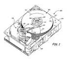
- FIG. 1is a perspective view of a data storage system.
- FIG. 2is a perspective view of a suspension, during manufacture, in accordance with an embodiment of the present invention.
- FIG. 3is an enlarged view of a load beam section and a gimbal section of the suspension of FIG. 2 in accordance with an embodiment of the present invention.
- FIG. 4is a perspective view of the suspension of FIG. 2 , after manufacture, in accordance with an embodiment of the present invention.
- FIG. 5is a perspective view of a suspension, during manufacture, in accordance with an alternative embodiment of the present invention.
- FIG. 6is a perspective view of the suspension of FIG. 5 , after manufacture, in accordance with an alternative embodiment of the present invention.
- FIG. 1is a perspective view of a disc drive 100 in which embodiments of the present invention are useful.
- Disc drive 100includes a base 102 and a top cover (not shown).
- Disc drive 100further includes a disc pack 106 , which is mounted on a spindle motor (not shown) by a disc clamp 108 .
- Disc pack 106includes a plurality of individual discs 107 , which are mounted for co-rotation about central axis 109 .
- Each disc surfacehas an associated slider 110 , which carries a transducer for communication with the disc surface.
- Each slider 110is supported by a suspension 112 which is in turn attached to a track accessing arm 114 of an actuator mechanism 116 .
- Actuator mechanism 116is rotated about a shaft 120 by a voice coil motor 118 , which is controlled by servo control circuitry within internal circuit 130 .
- voice coil motor 118rotates actuator mechanism 116 , sliders 110 move in an arcuate path 122 between a disc inner diameter 124 and a disc outer diameter 126 .
- FIG. 1illustrates one manner of actuating the data head proximate a data storage medium
- the present inventionis applicable to systems that use other actuation techniques, such as a linear actuator.
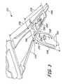
- FIG. 2is a perspective view of suspension 212 , during manufacture, in accordance with an embodiment of the present invention.
- suspension 212is formed with a progressive die manufacturing process.
- a progressive die manufacturing processis a process wherein suspension 212 undergoes multiple operations of punching and bending at high production rates.
- suspension 212has undergone a shearing process to cut the suspension material by subjecting suspension 212 to shear stresses between a punch and die.
- etchingcan be used to form suspension 212 as illustrated in FIG. 2 .
- Suspension 212is a single, continuous piece of stainless steel or other metallic and/or non-metallic material that has a substantially planar main body with top surface 235 and bottom surface 237 .
- Suspension 212includes a baseplate section 234 , load beam section 236 , gimbal section 238 and dimple section 239 .
- Those skilled in the artwill recognize that although suspension 212 is a single, continuous piece of material, portions of suspension 212 can be formed with multiple pieces of material in other embodiments.
- gimbal section 238 of FIG. 2is not yet a finished manufactured piece.
- Baseplate section 234is located at a proximal end of load beam section 236 and includes an actuator mounting aperture 240 for mounting suspension 212 to a respective track accessing arm, such as track accessing arm 114 as illustrated in FIG. 1 .
- baseplate section 234can be mounted to a track accessing arm by ball-staking. Those skilled in the art will recognize that other methods of attachment could be used.
- Load beam section 236includes a preload bend 242 , stiffening rails 244 and load/unload feature 258 .
- Preload bend 242supplies a preload force to a slider, such as slider 110 illustrated in FIG. 1 , which forces the slider towards the surface of a disc, such as disc 107 illustrated in FIG. 1 .
- preload bend 242is located in an area that has been thinned by a partial chemical etch. Those skilled in the art should recognize that in other embodiments a chemical etch is not needed.
- Load beam section 236includes stiffening rails 244 that provide additional stiffness to load beam section 236 . This additional stiffness transfers the preload force generated by preload bend 242 to the slider.
- stiffening rails 244are thinned by a partial chemical etch such that the bending operation that forms the rails and the preload bend does not creep into the planar main body of load beam section 236 . It should be noted that the manufacturing process in FIG. 2 does not yet show stiffening rails 244 bent out-of-plane with respect to the planar main body of the load beam section 236 .
- Load beam section 236also includes load/unload feature 258 , which is located at distal end 259 of suspension 212 .
- Load/unload feature 258provides a location for suspension 212 to ramp up when the track accessing arm is at rest.
- Gimbal section 238has a first end 246 formed with load beam section 236 , between baseplate section 234 and distal end 259 .
- Gimbal section 238includes central tongue 248 , gimbal arms 250 and deflection limiter 254 .
- central tongue 248is at least partially chemically etched.
- Gimbal arms 250are bent out-of-plane with respect to central tongue 248 by offset bends 252 .
- Gimbal arms 250provide out-of-plane pitch and roll flexibility and in-plane stiffness.
- Deflection limiter 254has a first end 256 formed with central tongue 248 . Deflection limiter 254 limits deflection of and damage to gimbal section 238 during ramp load/unload.
- Central tongue 248provides a surface on which to attach a slider following manufacture of suspension 212 .
- Dimple section 239is formed with load beam section 236 , between a proximal end of load beam section 236 and distal end 259 .
- Dimple section 239includes dimple 260 and a plurality of apertures.
- Dimple 260provides a load point at which the preload force can be transferred to the slider when the slider is attached to gimbal section 238 .
- the plurality of aperturesprovide alignment capabilities to load beam section 236 .
- aperture 257provides a locking position for deflection limiter 254 .
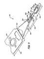
- FIG. 3is a perspective view of suspension 212 during a bending process of manufacture in accordance with an embodiment of the present invention.
- Stiffening rails 244are bent out-of-plane with respect to the main body portion of load beam section 236 at an angle substantially perpendicular to the main body portion of load beam section 236 in order to offset gimbal arms 250 from gimbal tongue 248 .
- FIG. 3shows a partially-formed bend along first end 246 , which folds gimbal section 238 under the main body portion of load beam section 236 .
- first end 256 of deflection limiter 254is bent such that the deflection limiter 254 is in a plane substantially normal to gimbal tongue 248 such that it will fit through aperture 257 in dimple section 239 as gimbal section 238 is bent along first end 246 .
- FIG. 4is a perspective view of suspension 212 , after manufacture, in accordance with an embodiment of the present invention.
- Gimbal section 238has been fully bent along first end 246 to form a hem seam, for example. This hem seam is strong enough to replicate welding of gimbal section 238 to load beam section 236 .
- gimbal section 238is generally parallel to load beam section 236 with bottom surface 237 of the suspension material along gimbal section 238 facing bottom surface 237 of the material along load beam section 236 .
- deflection limiter 254is fully-formed, and locked within a narrow slot in aperture 257 .
- FIG. 5is a perspective view of suspension 512 , during manufacture, in accordance with an another embodiment of the present invention.
- suspension 512is formed with the progressive die manufacturing process as previously discussed. However, those skilled in the art will recognize that other manufacturing processes can be used to form suspension 512 as illustrated in FIG. 5 .
- Suspension 512is a single, continuous piece of stainless steel or other metallic and/or non-metallic material that has a substantially planar main body with top surface 535 and bottom surface 537 .
- Suspension 212includes a baseplate section 534 , load beam section 536 , gimbal section 538 and dimple section 539 .
- Those skilled in the artwill recognize that although suspension 512 is a single, continuous piece of material, portions of suspension 512 can be formed with multiple pieces of material in other embodiments.
- gimbal section 538 of FIG. 5is not yet a finished manufactured piece.
- Baseplate section 534is located at a proximal end of load beam section 536 and includes an actuator mounting aperture 540 for mounting suspension 512 to a respective track accessing arm, such as track accessing arm 114 as illustrated in FIG. 1 .
- Load beam section 536includes a preload bend 542 and stiffening rails 544 . It should be noted that stiffening rails 544 are not yet bent out-of-plane with respect to the planar main body of the load beam section 536 .
- Load beam section 536also includes a distal end 559 .
- gimbal section 538has a first end 546 formed with load beam section 536 at distal end 559 , rather than in the main body portion as shown in FIG. 2 .
- Gimbal section 538includes central tongue 548 , gimbal arms 550 and deflection limiter 554 .
- Central tongue 548is partially chemically etched while gimbal arms 550 are bent out-of-plane with respect to central tongue 548 by offsets bends 552 .
- Deflection limiter 554has a first end 556 formed with central tongue 548 of gimbal section 538 .
- Dimple section 539is formed with load beam section 536 , between a proximal end of load beam section 536 and distal end 559 .
- Dimple section 539includes dimple 560 and a plurality of apertures.
- Dimple 560provides a load point which the preload force can be transferred to the slider when the slider is attached to gimbal section 538 .
- the plurality of aperturesprovide alignment capabilities to load beam section 536 .
- aperture 557provides a locking position for deflection limiter 554 .
- FIG. 6is a perspective view of suspension 512 , after manufacture, in accordance with an embodiment of the present invention.
- suspension 512has undergone the bending process, such that stiffening rails 544 are bent out-of-plane with respect to the main body portion of load beam section 536 and gimbal section 538 has been fully bent along first end 546 .
- Bottom surface 537 along gimbal section 538faces bottom surface 537 along load beam section 536 .
- deflection limiter 554is bent along first end 556 such that the deflection limiter 554 is in a plane substantially normal to a plane of gimbal section 538 .
- FIGS. 1-6are provided as examples only.
- the gimbal sectioncan be attached to the load beam section on any surface or edge of the material in other embodiments of the present invention.
Landscapes
- Supporting Of Heads In Record-Carrier Devices (AREA)
Abstract
Description
Claims (20)
Priority Applications (1)
| Application Number | Priority Date | Filing Date | Title |
|---|---|---|---|
| US10/640,334US7283332B2 (en) | 2003-08-13 | 2003-08-13 | Suspension with improved gimbal |
Applications Claiming Priority (1)
| Application Number | Priority Date | Filing Date | Title |
|---|---|---|---|
| US10/640,334US7283332B2 (en) | 2003-08-13 | 2003-08-13 | Suspension with improved gimbal |
Publications (2)
| Publication Number | Publication Date |
|---|---|
| US20050036239A1 US20050036239A1 (en) | 2005-02-17 |
| US7283332B2true US7283332B2 (en) | 2007-10-16 |
Family
ID=34136070
Family Applications (1)
| Application Number | Title | Priority Date | Filing Date |
|---|---|---|---|
| US10/640,334Expired - LifetimeUS7283332B2 (en) | 2003-08-13 | 2003-08-13 | Suspension with improved gimbal |
Country Status (1)
| Country | Link |
|---|---|
| US (1) | US7283332B2 (en) |
Cited By (11)
| Publication number | Priority date | Publication date | Assignee | Title |
|---|---|---|---|---|
| US20060028767A1 (en)* | 2004-08-03 | 2006-02-09 | Sae Magnetics (H.K.) Ltd. | Head arm assembly, head stack assembly and disk drive unit using the same |
| US20060139811A1 (en)* | 2004-12-28 | 2006-06-29 | Samsung Electronics Co., Ltd. | Suspension and actuator with the same for use in hard disk drive |
| US20060209465A1 (en)* | 2005-03-17 | 2006-09-21 | Kenichi Takikawa | Head suspension |
| US20060250725A1 (en)* | 2005-05-09 | 2006-11-09 | Nhk Spring Co., Ltd. | Head suspension |
| US20060260118A1 (en)* | 2005-05-09 | 2006-11-23 | Nhk Spring Co., Ltd. | Method of manufacturing head suspension |
| US20060260119A1 (en)* | 2005-05-09 | 2006-11-23 | Nhk Spring Co., Ltd. | Method of manufacturing head suspension |
| US20070115591A1 (en)* | 2005-11-21 | 2007-05-24 | Sae Magnetics (H.K.) Ltd. | Suspension, head gimbal assembly and disk drive unit with the same |
| US20080144223A1 (en)* | 2006-12-14 | 2008-06-19 | Hitachi Global Storage Technologies Netherlands B. V. | Magnetic disk drive and suspension assembly adopted therein |
| US20100315744A1 (en)* | 2009-06-15 | 2010-12-16 | Seagate Technology Llc | Slider-gimbal scratch mitigation |
| US20100315745A1 (en)* | 2009-06-15 | 2010-12-16 | Seagate Technology Llc | Protective layer on gimbal for scratch mitigation |
| JP2013008430A (en)* | 2011-05-20 | 2013-01-10 | Suncall Corp | Magnetic head suspension |
Families Citing this family (4)
| Publication number | Priority date | Publication date | Assignee | Title |
|---|---|---|---|---|
| JP2006053971A (en)* | 2004-08-10 | 2006-02-23 | Hitachi Global Storage Technologies Netherlands Bv | Suspension, magnetic head assembly, and magnetic disk drive |
| US7724476B1 (en)* | 2004-09-16 | 2010-05-25 | Hutchinson Technology Incorporated | Coined headlift with formed rail offset for a disk drive head suspension component |
| US7701673B2 (en)* | 2005-05-17 | 2010-04-20 | Sae Magnetics (Hk) Ltd. | Gimbal design with solder ball bond pads and trailing edge limiter tab for a recording head |
| JP2021140843A (en)* | 2020-03-04 | 2021-09-16 | 株式会社東芝 | Suspension assembly and disk device |
Citations (25)
| Publication number | Priority date | Publication date | Assignee | Title |
|---|---|---|---|---|
| JPS586552A (en)* | 1981-07-02 | 1983-01-14 | Comput Basic Mach Technol Res Assoc | Manufacture for magnetic head assembly |
| JPS59193581A (en)* | 1983-04-18 | 1984-11-02 | Toshiba Corp | Head slider support mechanism |
| JPS60167172A (en)* | 1984-02-10 | 1985-08-30 | Fujitsu Ltd | Magnetic head supporting mechanism |
| JPH01128277A (en)* | 1987-11-12 | 1989-05-19 | Nec Corp | Magnetic head |
| US5299080A (en)* | 1989-12-27 | 1994-03-29 | Matsushita Electric Industrial Co., Ltd. | Floating head slider with improved suspension for use in magnetic/optical disk recording apparatuses |
| JPH0793927A (en)* | 1993-09-24 | 1995-04-07 | Fujitsu Ltd | Magnetic head support mechanism for magnetic disk drive |
| JPH07105649A (en)* | 1993-10-05 | 1995-04-21 | Sankoole Kk | Magnetic head support structure and its manufacture |
| US5428490A (en) | 1992-11-12 | 1995-06-27 | Seagate Technology, Inc. | One-piece flexure having an etched load point button |
| JPH08329636A (en)* | 1995-03-31 | 1996-12-13 | Toshiba Corp | Head support mechanism and recording / reproducing apparatus using the same |
| US5608590A (en) | 1994-06-20 | 1997-03-04 | Hutchinson Technology Incorporated | Gimballing flexure with static compensation and load print intregal etched features |
| US5612841A (en) | 1993-06-15 | 1997-03-18 | Seagate Technology, Inc. | Flexure assembly for hard disc drive heads |
| US5711063A (en) | 1996-06-11 | 1998-01-27 | Seagate Technology, Inc. | Method of forming a suspension fabricated from silicon |
| JPH117740A (en)* | 1997-06-18 | 1999-01-12 | Nippon Mektron Ltd | Suspension for magnetic head |
| JPH1166782A (en)* | 1997-08-14 | 1999-03-09 | Tdk Corp | Magnetic head supporting mechanism |
| JPH11213590A (en)* | 1998-01-20 | 1999-08-06 | Nec Corp | Magnetic head slider supporting mechanism and magnetic disk device provided with the same |
| US6115221A (en)* | 1996-12-03 | 2000-09-05 | Nec Corporation | Magnetic head slider support mechanism and magnetic disk storage |
| JP2000298966A (en)* | 1999-04-14 | 2000-10-24 | Hitachi Ltd | Suspension for magnetic head |
| US6147840A (en) | 1999-04-15 | 2000-11-14 | Magnecomp Corp. | One-piece load beam and gimbal flexure using flexible circuit |
| US6304420B1 (en)* | 1998-01-20 | 2001-10-16 | Seagate Technology Llc | Preloaded gimbal in a head suspension for limiting head/disc separation |
| US6373662B1 (en) | 1990-11-09 | 2002-04-16 | Hutchinson Technology Incorporated | Partially etched flexure arms in an integrated gimbal suspension |
| US6392844B1 (en)* | 2000-04-21 | 2002-05-21 | Magnecomp Corp. | Single piece suspension with self-hinged flexure |
| US6424498B1 (en)* | 1999-12-03 | 2002-07-23 | Seagate Technology Llc | Shock resistant suspension limiter for a disc drive |
| JP2002245741A (en)* | 2001-02-19 | 2002-08-30 | Sony Corp | Support structure for magnetic head and magnetic disk driving device |
| US20030086207A1 (en)* | 2001-11-08 | 2003-05-08 | Nhk Spring Co., Ltd. | Disc drive suspension |
| US7006332B2 (en)* | 2003-01-08 | 2006-02-28 | Shin-Etsu Chemical Co., Ltd. | Disk drive comprising suspension for magnetic head with positioning of slider to predetermined track through oscillation of voice coil motor |
- 2003
- 2003-08-13USUS10/640,334patent/US7283332B2/ennot_activeExpired - Lifetime
Patent Citations (36)
| Publication number | Priority date | Publication date | Assignee | Title |
|---|---|---|---|---|
| JPS586552A (en)* | 1981-07-02 | 1983-01-14 | Comput Basic Mach Technol Res Assoc | Manufacture for magnetic head assembly |
| JPS59193581A (en)* | 1983-04-18 | 1984-11-02 | Toshiba Corp | Head slider support mechanism |
| JPS60167172A (en)* | 1984-02-10 | 1985-08-30 | Fujitsu Ltd | Magnetic head supporting mechanism |
| JPH01128277A (en)* | 1987-11-12 | 1989-05-19 | Nec Corp | Magnetic head |
| US5299080A (en)* | 1989-12-27 | 1994-03-29 | Matsushita Electric Industrial Co., Ltd. | Floating head slider with improved suspension for use in magnetic/optical disk recording apparatuses |
| US6373662B1 (en) | 1990-11-09 | 2002-04-16 | Hutchinson Technology Incorporated | Partially etched flexure arms in an integrated gimbal suspension |
| US20020034039A1 (en) | 1992-11-12 | 2002-03-21 | Seagate Technology, Inc. | One-piece flexure for small magnetic heads |
| US20020012202A1 (en) | 1992-11-12 | 2002-01-31 | Seagate Technology, Inc. | One-piece flexure for small magnetic heads |
| US5434731A (en) | 1992-11-12 | 1995-07-18 | Seagate Technology, Inc. | Process for making a one-piece flexure for small magnetic heads |
| US5504640A (en) | 1992-11-12 | 1996-04-02 | Seagate Technology, Inc. | One-piece flexure for small magnetic heads |
| US5923500A (en) | 1992-11-12 | 1999-07-13 | Seagate Technology, Inc. | One-piece flexure for small magnetic heads |
| US20020034051A1 (en) | 1992-11-12 | 2002-03-21 | Seagate Technology, Inc. | One-piece flexure for small magnetic heads |
| US5638234A (en) | 1992-11-12 | 1997-06-10 | Seagate Technology, Inc. | Flexure with reduced unloaded height for hard disc drive heads |
| US5428490A (en) | 1992-11-12 | 1995-06-27 | Seagate Technology, Inc. | One-piece flexure having an etched load point button |
| US6397455B1 (en) | 1992-11-12 | 2002-06-04 | Seagate Technology, Inc. | Method for forming a one-piece flexure for small magnetic heads |
| US5612841A (en) | 1993-06-15 | 1997-03-18 | Seagate Technology, Inc. | Flexure assembly for hard disc drive heads |
| JPH0793927A (en)* | 1993-09-24 | 1995-04-07 | Fujitsu Ltd | Magnetic head support mechanism for magnetic disk drive |
| JPH07105649A (en)* | 1993-10-05 | 1995-04-21 | Sankoole Kk | Magnetic head support structure and its manufacture |
| US5608590A (en) | 1994-06-20 | 1997-03-04 | Hutchinson Technology Incorporated | Gimballing flexure with static compensation and load print intregal etched features |
| US5901430A (en) | 1994-06-20 | 1999-05-11 | Hutchinson Technology Incorporated | Method of making integral static compensation features |
| JPH08329636A (en)* | 1995-03-31 | 1996-12-13 | Toshiba Corp | Head support mechanism and recording / reproducing apparatus using the same |
| US5711063A (en) | 1996-06-11 | 1998-01-27 | Seagate Technology, Inc. | Method of forming a suspension fabricated from silicon |
| US5896246A (en) | 1996-06-11 | 1999-04-20 | Seagate Technology, Inc. | Suspension fabricated from silicon |
| US6115221A (en)* | 1996-12-03 | 2000-09-05 | Nec Corporation | Magnetic head slider support mechanism and magnetic disk storage |
| JPH117740A (en)* | 1997-06-18 | 1999-01-12 | Nippon Mektron Ltd | Suspension for magnetic head |
| JPH1166782A (en)* | 1997-08-14 | 1999-03-09 | Tdk Corp | Magnetic head supporting mechanism |
| US6304420B1 (en)* | 1998-01-20 | 2001-10-16 | Seagate Technology Llc | Preloaded gimbal in a head suspension for limiting head/disc separation |
| US6215626B1 (en)* | 1998-01-20 | 2001-04-10 | Nec Corporation | Magnetic head slider support mechanism with improved load distribution and a magnetic disk drive utilizing same |
| JPH11213590A (en)* | 1998-01-20 | 1999-08-06 | Nec Corp | Magnetic head slider supporting mechanism and magnetic disk device provided with the same |
| JP2000298966A (en)* | 1999-04-14 | 2000-10-24 | Hitachi Ltd | Suspension for magnetic head |
| US6147840A (en) | 1999-04-15 | 2000-11-14 | Magnecomp Corp. | One-piece load beam and gimbal flexure using flexible circuit |
| US6424498B1 (en)* | 1999-12-03 | 2002-07-23 | Seagate Technology Llc | Shock resistant suspension limiter for a disc drive |
| US6392844B1 (en)* | 2000-04-21 | 2002-05-21 | Magnecomp Corp. | Single piece suspension with self-hinged flexure |
| JP2002245741A (en)* | 2001-02-19 | 2002-08-30 | Sony Corp | Support structure for magnetic head and magnetic disk driving device |
| US20030086207A1 (en)* | 2001-11-08 | 2003-05-08 | Nhk Spring Co., Ltd. | Disc drive suspension |
| US7006332B2 (en)* | 2003-01-08 | 2006-02-28 | Shin-Etsu Chemical Co., Ltd. | Disk drive comprising suspension for magnetic head with positioning of slider to predetermined track through oscillation of voice coil motor |
Cited By (19)
| Publication number | Priority date | Publication date | Assignee | Title |
|---|---|---|---|---|
| US7463453B2 (en)* | 2004-08-03 | 2008-12-09 | Sae Magnetics (H.K.) Ltd. | Head arm assembly, head stack assembly and disk drive unit using the same |
| US20060028767A1 (en)* | 2004-08-03 | 2006-02-09 | Sae Magnetics (H.K.) Ltd. | Head arm assembly, head stack assembly and disk drive unit using the same |
| US20060139811A1 (en)* | 2004-12-28 | 2006-06-29 | Samsung Electronics Co., Ltd. | Suspension and actuator with the same for use in hard disk drive |
| US20060209465A1 (en)* | 2005-03-17 | 2006-09-21 | Kenichi Takikawa | Head suspension |
| US7595962B2 (en)* | 2005-03-17 | 2009-09-29 | Nhk Spring Co., Ltd. | Head suspension having rigid part rail diminished at longitudinal curve |
| US20060260118A1 (en)* | 2005-05-09 | 2006-11-23 | Nhk Spring Co., Ltd. | Method of manufacturing head suspension |
| US7688550B2 (en) | 2005-05-09 | 2010-03-30 | Nhk Spring Co., Ltd. | Head suspension |
| US7673381B2 (en) | 2005-05-09 | 2010-03-09 | Nhk Spring Co., Ltd. | Method of manufacturing head suspension |
| US20060260119A1 (en)* | 2005-05-09 | 2006-11-23 | Nhk Spring Co., Ltd. | Method of manufacturing head suspension |
| US20060250725A1 (en)* | 2005-05-09 | 2006-11-09 | Nhk Spring Co., Ltd. | Head suspension |
| US7650685B2 (en) | 2005-05-09 | 2010-01-26 | Nhk Spring Co., Ltd. | Method of manufacturing head suspension |
| US20070115591A1 (en)* | 2005-11-21 | 2007-05-24 | Sae Magnetics (H.K.) Ltd. | Suspension, head gimbal assembly and disk drive unit with the same |
| US20080144223A1 (en)* | 2006-12-14 | 2008-06-19 | Hitachi Global Storage Technologies Netherlands B. V. | Magnetic disk drive and suspension assembly adopted therein |
| US8130470B2 (en)* | 2006-12-14 | 2012-03-06 | Hitachi Global Storage Technologies, Netherlands B.V. | Suspension assembly including a limiter having a gross length larger than a between-coupling-portions distance between coupling portions |
| US20100315744A1 (en)* | 2009-06-15 | 2010-12-16 | Seagate Technology Llc | Slider-gimbal scratch mitigation |
| US20100315745A1 (en)* | 2009-06-15 | 2010-12-16 | Seagate Technology Llc | Protective layer on gimbal for scratch mitigation |
| US8300362B2 (en) | 2009-06-15 | 2012-10-30 | Seagate Technology Llc | Slider-gimbal scratch mitigation |
| US8493689B2 (en) | 2009-06-15 | 2013-07-23 | Seagate Technology Llc | Protective layer on gimbal for scratch mitigation |
| JP2013008430A (en)* | 2011-05-20 | 2013-01-10 | Suncall Corp | Magnetic head suspension |
Also Published As
| Publication number | Publication date |
|---|---|
| US20050036239A1 (en) | 2005-02-17 |
Similar Documents
| Publication | Publication Date | Title |
|---|---|---|
| US7283332B2 (en) | Suspension with improved gimbal | |
| US6151197A (en) | Water slide suspension assembly having a stiffened vertically offset lift tab | |
| EP0684595B1 (en) | Method for analysing and controlling in-plane stiffness of load beam within head-gimbal assembly of a hard disk drive | |
| US6046885A (en) | Base plate suspension assembly in a hard disk drive with step in flange | |
| US7313855B2 (en) | Method of forming a head suspension with an integral boss tower | |
| US7137187B2 (en) | Integrated lead suspension for high density drive | |
| US5504640A (en) | One-piece flexure for small magnetic heads | |
| US20090207528A1 (en) | Disc flutter compensating suspension | |
| US7130157B2 (en) | Head suspension having a displacement limiter | |
| US6063508A (en) | Swageable base plate with gram load offset and adjustment feature | |
| US20020075602A1 (en) | Head gimbal assembly flexure arm displacement limiter | |
| WO2001099104A2 (en) | Head pitch adjustment for disc drive | |
| US12230299B2 (en) | Low profile suspension design | |
| US6778362B1 (en) | Hinged load beam with torsional spring | |
| US7064931B2 (en) | Disc drive suspension optimized for preload bend damper | |
| US5455727A (en) | Transducer suspension assembly with a first pair of flanges for raising the resonant frequency and a second pair of flanges for increasing stiffness | |
| US6366430B1 (en) | Method and apparatus for improved static angle adjustment | |
| US6522624B2 (en) | Attachment and microactuation aids in a laminated suspension | |
| US6301080B1 (en) | Dither method to unload negative suction air bearings | |
| US7057856B2 (en) | Gimbal strut shape to increase buckling load | |
| US7502204B2 (en) | Structures for attaching a head gimbal assembly and an actuator arm | |
| US6940696B2 (en) | Head suspension for disk drive having a contact face to receive jig | |
| US7113370B2 (en) | Slanted mounting for preload flat suspension | |
| US20040012893A1 (en) | Aerodynamic actuator assembly | |
| US20030202282A1 (en) | Method of manufacturing a suspension using coining |
Legal Events
| Date | Code | Title | Description |
|---|---|---|---|
| AS | Assignment | Owner name:SEAGATE TECHNOLOGY LLC, CALIFORNIA Free format text:ASSIGNMENT OF ASSIGNORS INTEREST;ASSIGNOR:WEBER, STEVEN LEE;REEL/FRAME:014406/0648 Effective date:20030805 | |
| STCF | Information on status: patent grant | Free format text:PATENTED CASE | |
| AS | Assignment | Owner name:WELLS FARGO BANK, NATIONAL ASSOCIATION, AS COLLATERAL AGENT AND SECOND PRIORITY REPRESENTATIVE, CALIFORNIA Free format text:SECURITY AGREEMENT;ASSIGNORS:MAXTOR CORPORATION;SEAGATE TECHNOLOGY LLC;SEAGATE TECHNOLOGY INTERNATIONAL;REEL/FRAME:022757/0017 Effective date:20090507 Owner name:JPMORGAN CHASE BANK, N.A., AS ADMINISTRATIVE AGENT AND FIRST PRIORITY REPRESENTATIVE, NEW YORK Free format text:SECURITY AGREEMENT;ASSIGNORS:MAXTOR CORPORATION;SEAGATE TECHNOLOGY LLC;SEAGATE TECHNOLOGY INTERNATIONAL;REEL/FRAME:022757/0017 Effective date:20090507 Owner name:JPMORGAN CHASE BANK, N.A., AS ADMINISTRATIVE AGENT Free format text:SECURITY AGREEMENT;ASSIGNORS:MAXTOR CORPORATION;SEAGATE TECHNOLOGY LLC;SEAGATE TECHNOLOGY INTERNATIONAL;REEL/FRAME:022757/0017 Effective date:20090507 Owner name:WELLS FARGO BANK, NATIONAL ASSOCIATION, AS COLLATE Free format text:SECURITY AGREEMENT;ASSIGNORS:MAXTOR CORPORATION;SEAGATE TECHNOLOGY LLC;SEAGATE TECHNOLOGY INTERNATIONAL;REEL/FRAME:022757/0017 Effective date:20090507 | |
| AS | Assignment | Owner name:SEAGATE TECHNOLOGY INTERNATIONAL, CALIFORNIA Free format text:RELEASE;ASSIGNOR:JPMORGAN CHASE BANK, N.A., AS ADMINISTRATIVE AGENT;REEL/FRAME:025662/0001 Effective date:20110114 Owner name:SEAGATE TECHNOLOGY HDD HOLDINGS, CALIFORNIA Free format text:RELEASE;ASSIGNOR:JPMORGAN CHASE BANK, N.A., AS ADMINISTRATIVE AGENT;REEL/FRAME:025662/0001 Effective date:20110114 Owner name:MAXTOR CORPORATION, CALIFORNIA Free format text:RELEASE;ASSIGNOR:JPMORGAN CHASE BANK, N.A., AS ADMINISTRATIVE AGENT;REEL/FRAME:025662/0001 Effective date:20110114 Owner name:SEAGATE TECHNOLOGY LLC, CALIFORNIA Free format text:RELEASE;ASSIGNOR:JPMORGAN CHASE BANK, N.A., AS ADMINISTRATIVE AGENT;REEL/FRAME:025662/0001 Effective date:20110114 | |
| AS | Assignment | Owner name:THE BANK OF NOVA SCOTIA, AS ADMINISTRATIVE AGENT, CANADA Free format text:SECURITY AGREEMENT;ASSIGNOR:SEAGATE TECHNOLOGY LLC;REEL/FRAME:026010/0350 Effective date:20110118 Owner name:THE BANK OF NOVA SCOTIA, AS ADMINISTRATIVE AGENT, Free format text:SECURITY AGREEMENT;ASSIGNOR:SEAGATE TECHNOLOGY LLC;REEL/FRAME:026010/0350 Effective date:20110118 | |
| FPAY | Fee payment | Year of fee payment:4 | |
| AS | Assignment | Owner name:SEAGATE TECHNOLOGY US HOLDINGS, INC., CALIFORNIA Free format text:TERMINATION AND RELEASE OF SECURITY INTEREST IN PATENT RIGHTS;ASSIGNOR:WELLS FARGO BANK, NATIONAL ASSOCIATION, AS COLLATERAL AGENT AND SECOND PRIORITY REPRESENTATIVE;REEL/FRAME:030833/0001 Effective date:20130312 Owner name:EVAULT INC. (F/K/A I365 INC.), CALIFORNIA Free format text:TERMINATION AND RELEASE OF SECURITY INTEREST IN PATENT RIGHTS;ASSIGNOR:WELLS FARGO BANK, NATIONAL ASSOCIATION, AS COLLATERAL AGENT AND SECOND PRIORITY REPRESENTATIVE;REEL/FRAME:030833/0001 Effective date:20130312 Owner name:SEAGATE TECHNOLOGY LLC, CALIFORNIA Free format text:TERMINATION AND RELEASE OF SECURITY INTEREST IN PATENT RIGHTS;ASSIGNOR:WELLS FARGO BANK, NATIONAL ASSOCIATION, AS COLLATERAL AGENT AND SECOND PRIORITY REPRESENTATIVE;REEL/FRAME:030833/0001 Effective date:20130312 Owner name:SEAGATE TECHNOLOGY INTERNATIONAL, CAYMAN ISLANDS Free format text:TERMINATION AND RELEASE OF SECURITY INTEREST IN PATENT RIGHTS;ASSIGNOR:WELLS FARGO BANK, NATIONAL ASSOCIATION, AS COLLATERAL AGENT AND SECOND PRIORITY REPRESENTATIVE;REEL/FRAME:030833/0001 Effective date:20130312 | |
| FPAY | Fee payment | Year of fee payment:8 | |
| MAFP | Maintenance fee payment | Free format text:PAYMENT OF MAINTENANCE FEE, 12TH YEAR, LARGE ENTITY (ORIGINAL EVENT CODE: M1553); ENTITY STATUS OF PATENT OWNER: LARGE ENTITY Year of fee payment:12 | |
| AS | Assignment | Owner name:SEAGATE TECHNOLOGY PUBLIC LIMITED COMPANY, CALIFORNIA Free format text:RELEASE BY SECURED PARTY;ASSIGNOR:THE BANK OF NOVA SCOTIA;REEL/FRAME:072193/0001 Effective date:20250303 Owner name:SEAGATE TECHNOLOGY, CALIFORNIA Free format text:RELEASE BY SECURED PARTY;ASSIGNOR:THE BANK OF NOVA SCOTIA;REEL/FRAME:072193/0001 Effective date:20250303 Owner name:SEAGATE TECHNOLOGY HDD HOLDINGS, CALIFORNIA Free format text:RELEASE BY SECURED PARTY;ASSIGNOR:THE BANK OF NOVA SCOTIA;REEL/FRAME:072193/0001 Effective date:20250303 Owner name:I365 INC., CALIFORNIA Free format text:RELEASE BY SECURED PARTY;ASSIGNOR:THE BANK OF NOVA SCOTIA;REEL/FRAME:072193/0001 Effective date:20250303 Owner name:SEAGATE TECHNOLOGY LLC, CALIFORNIA Free format text:RELEASE BY SECURED PARTY;ASSIGNOR:THE BANK OF NOVA SCOTIA;REEL/FRAME:072193/0001 Effective date:20250303 Owner name:SEAGATE TECHNOLOGY INTERNATIONAL, CAYMAN ISLANDS Free format text:RELEASE BY SECURED PARTY;ASSIGNOR:THE BANK OF NOVA SCOTIA;REEL/FRAME:072193/0001 Effective date:20250303 Owner name:SEAGATE HDD CAYMAN, CAYMAN ISLANDS Free format text:RELEASE BY SECURED PARTY;ASSIGNOR:THE BANK OF NOVA SCOTIA;REEL/FRAME:072193/0001 Effective date:20250303 Owner name:SEAGATE TECHNOLOGY (US) HOLDINGS, INC., CALIFORNIA Free format text:RELEASE BY SECURED PARTY;ASSIGNOR:THE BANK OF NOVA SCOTIA;REEL/FRAME:072193/0001 Effective date:20250303 |