US7282038B2 - Compression apparatus - Google Patents
Compression apparatusDownload PDFInfo
- Publication number
- US7282038B2 US7282038B2US10/784,604US78460404AUS7282038B2US 7282038 B2US7282038 B2US 7282038B2US 78460404 AUS78460404 AUS 78460404AUS 7282038 B2US7282038 B2US 7282038B2
- Authority
- US
- United States
- Prior art keywords
- foot
- layer
- compression apparatus
- piece
- sleeve
- Prior art date
- Legal status (The legal status is an assumption and is not a legal conclusion. Google has not performed a legal analysis and makes no representation as to the accuracy of the status listed.)
- Expired - Lifetime, expires
Links
Images


Classifications
- A—HUMAN NECESSITIES
- A61—MEDICAL OR VETERINARY SCIENCE; HYGIENE
- A61H—PHYSICAL THERAPY APPARATUS, e.g. DEVICES FOR LOCATING OR STIMULATING REFLEX POINTS IN THE BODY; ARTIFICIAL RESPIRATION; MASSAGE; BATHING DEVICES FOR SPECIAL THERAPEUTIC OR HYGIENIC PURPOSES OR SPECIFIC PARTS OF THE BODY
- A61H9/00—Pneumatic or hydraulic massage
- A61H9/005—Pneumatic massage
- A61H9/0078—Pneumatic massage with intermittent or alternately inflated bladders or cuffs
- A—HUMAN NECESSITIES
- A61—MEDICAL OR VETERINARY SCIENCE; HYGIENE
- A61F—FILTERS IMPLANTABLE INTO BLOOD VESSELS; PROSTHESES; DEVICES PROVIDING PATENCY TO, OR PREVENTING COLLAPSING OF, TUBULAR STRUCTURES OF THE BODY, e.g. STENTS; ORTHOPAEDIC, NURSING OR CONTRACEPTIVE DEVICES; FOMENTATION; TREATMENT OR PROTECTION OF EYES OR EARS; BANDAGES, DRESSINGS OR ABSORBENT PADS; FIRST-AID KITS
- A61F13/00—Bandages or dressings; Absorbent pads
- A61F13/06—Bandages or dressings; Absorbent pads specially adapted for feet or legs; Corn-pads; Corn-rings
- A—HUMAN NECESSITIES
- A61—MEDICAL OR VETERINARY SCIENCE; HYGIENE
- A61H—PHYSICAL THERAPY APPARATUS, e.g. DEVICES FOR LOCATING OR STIMULATING REFLEX POINTS IN THE BODY; ARTIFICIAL RESPIRATION; MASSAGE; BATHING DEVICES FOR SPECIAL THERAPEUTIC OR HYGIENIC PURPOSES OR SPECIFIC PARTS OF THE BODY
- A61H2201/00—Characteristics of apparatus not provided for in the preceding codes
- A61H2201/16—Physical interface with patient
- A61H2201/1602—Physical interface with patient kind of interface, e.g. head rest, knee support or lumbar support
- A61H2201/165—Wearable interfaces
- A—HUMAN NECESSITIES
- A61—MEDICAL OR VETERINARY SCIENCE; HYGIENE
- A61H—PHYSICAL THERAPY APPARATUS, e.g. DEVICES FOR LOCATING OR STIMULATING REFLEX POINTS IN THE BODY; ARTIFICIAL RESPIRATION; MASSAGE; BATHING DEVICES FOR SPECIAL THERAPEUTIC OR HYGIENIC PURPOSES OR SPECIFIC PARTS OF THE BODY
- A61H2201/00—Characteristics of apparatus not provided for in the preceding codes
- A61H2201/16—Physical interface with patient
- A61H2201/1683—Surface of interface
- A61H2201/169—Physical characteristics of the surface, e.g. material, relief, texture or indicia
- A61H2201/1697—Breathability of the material
- A—HUMAN NECESSITIES
- A61—MEDICAL OR VETERINARY SCIENCE; HYGIENE
- A61H—PHYSICAL THERAPY APPARATUS, e.g. DEVICES FOR LOCATING OR STIMULATING REFLEX POINTS IN THE BODY; ARTIFICIAL RESPIRATION; MASSAGE; BATHING DEVICES FOR SPECIAL THERAPEUTIC OR HYGIENIC PURPOSES OR SPECIFIC PARTS OF THE BODY
- A61H2205/00—Devices for specific parts of the body
- A61H2205/12—Feet
- A—HUMAN NECESSITIES
- A61—MEDICAL OR VETERINARY SCIENCE; HYGIENE
- A61H—PHYSICAL THERAPY APPARATUS, e.g. DEVICES FOR LOCATING OR STIMULATING REFLEX POINTS IN THE BODY; ARTIFICIAL RESPIRATION; MASSAGE; BATHING DEVICES FOR SPECIAL THERAPEUTIC OR HYGIENIC PURPOSES OR SPECIFIC PARTS OF THE BODY
- A61H2209/00—Devices for avoiding blood stagnation, e.g. Deep Vein Thrombosis [DVT] devices
Definitions
- the present disclosuregenerally relates to the field of vascular therapy for application to a limb of a body, and more particularly, to a compression apparatus configured to artificially stimulate blood vessels of the limb.
- a major concern for immobile patients and persons alikeare medical conditions that form clots in the blood, such as, deep vein thrombosis (DVT) and peripheral edema.
- DVTdeep vein thrombosis
- Such patients and personsinclude those undergoing surgery, anesthesia and extended periods of bed rest.
- These blood clotting conditionsgenerally occur in the deep veins of the lower extremities and/or pelvis.
- These veinssuch as the iliac, femoral, popiteal and tibial return deoxygenated to the heart.
- a static pool of bloodis ideal for clot formations.
- a major risk associated with this conditionis interference with cardiovascular circulation. Most seriously, a fragment of the blood clot can break loose and migrate.
- a pulmonary embolican form blocking a main pulmonary artery, which may be life threatening.
- the conditions and resulting risks associated with patient immobilitymay be controlled or alleviated by applying intermittent pressure to a patient's limb, such as, for example, portions of a leg and foot to assist in blood circulation.
- a patient's limbsuch as, for example, portions of a leg and foot to assist in blood circulation.
- Known deviceshave been employed to assist in blood circulation, such as, one piece pads and compression boots. See, for example, U.S. Pat. Nos. 4,696,289 and 5,989,204.
- Compression devicesthat consist of an air pump connected to a disposable wraparound pad by one or more air tubes have been used.
- the wraparound padis placed around the patient's foot or other extremity. Air is then forced into the wraparound pad creating pressure around the parts of the foot or other extremity.
- a compression apparatus including the foot sleevereduces bulk and is not cumbersome during use to improve comfort and compliance to a patient. It is further contemplated that the compression apparatus is easily and efficiently manufactured.
- a compression apparatusthat prevents contamination, mitigates the incidence of skin breakdown and facilitates disposal with an extremity for overcoming the disadvantages and drawbacks of the prior art.
- a compression apparatus including the foot sleevereduces bulk and is not cumbersome during use to improve comfort and compliance to a patient.
- the compression apparatusis easily and efficiently fabricated.
- the embodiments of the compression apparatusare configured to provide vascular therapy, including for example the prevention of deep vein thrombosis (“DVT”) by artificially stimulating blood vessels throughout the foot of a patient, including the toes and the heel, to increase blood circulation for patients.
- the compression apparatus according to the present disclosureis an intermittent pneumatic compression device for applying slow compression to a foot. Such pressure simulates blood flow that would normally result from, for example, walking, by employing a foot sleeve that is supported about a foot of a patient.
- the compression apparatusmay have an inflatable bladder designed to cover and engage the entire area of the bottom of the foot, beyond the heel and ball to a substantial portion of the toes.
- the inflatable bladderwraps about the side portions of the foot via a hook and loop type connector flap that transverses the instep of the foot.
- the inflatable bladdermay include an outside layer and an inside layer.
- the bladdercan be formed by welding the outside layer and the inside layer together.
- the bladderprovides a uniform application of pressure to the entire foot and is then deflated.
- the compression apparatusmay include bladder sections that are capable of enabling venous refill detection.
- the compression apparatus according to the present disclosureincludes various embodiments and combinations as will be appreciated herein. The various embodiments and combinations may each be manufactured in various sizes to accommodate subjects of varying sizes as well as right and left foot models.
- the compression apparatusincludes a strap that improves comfort by using a single piece laminate structure whose inside layer is a cushioning layer.
- the strapis integrated with a foot sleeve by sandwiching the strap between separate layers of the foot sleeve body.
- the comfort to the patientmay be improved by segmenting the strap to contour about the heel of the foot.
- the strapcan also include one or more layers configured to provide a barrier to the cushioning layer from the environment.
- the foot sleevecan improve ease of use by having a universal design with a one flap metatarsal closure.
- the strapmay include a laminate consisting of various layers.
- the layersmay include a center layer that is configured for comfort. Outside layers disposed about the center layer provide a barrier between the environment and an outer surface of the foot. One of the outside layers can be a skin contact layer that is soft to the touch.
- the strapmay be a separate part integrated into the body of the foot sleeve by being sandwiched between separate layers of the foot sleeve body and then permanently secured.
- the body of the foot sleevemay be designed for adaptability to various foot sizes and shapes by employing a single metatarsal flap that facilitates ease of use.
- the bodymay be configured to provide inspection of the tops of the phalanges of the foot.
- the cushioning layerhas a soft skin contact layer.
- the foot sleevemay also include a liner that is configured to provide a physical barrier to the cushioning layer that assists in the prevention of contamination.
- the interior cushioning layerprovides comfort and mitigates skin breakdown.
- the foot sleeveimproves patient compliance and provides sanitation by isolating the cushioning layer from the environment.
- the foot sleeveis also easily manufactured, for instance, the material stack up contained in the layers allows the strap and/or foot sleeve to be cut as one piece and ensures an even stack up of materials.
- the compression apparatusincludes an expandable body configured for disposal about a foot.
- a strapextends from the body.
- the strapis configured for disposal about the foot adjacent an ankle.
- the straphas a first layer configured to engage an outer surface of the foot adjacent the ankle, a second layer and a third cushion layer disposed therebetween.
- the strapmay be integrally connected to the expandable body.
- the strapmay be monolithically formed with the expandable body.
- the expandable bodycan include a first, top layer and/or a second, bottom layer.
- a portion of the strap membermay be disposed between a top and bottom layer of the foot sleeve body.
- the strapmay have a segmented configuration for contour with the foot.
- the third cushion layercan be disposed within the first layer and the second layer such that the first layer and the second layer are configured to provide a barrier to the third cushion layer.
- the bodycan include a metatarsal strap.
- the first layerincludes a soft polyester material.
- the first layermay include a soft polyester material and polyvinylchloride.
- the third cushion layermay include a foam material.
- the second layercan have an outer surface including a loop material disposed therewith.
- the second layermay include a polyvinylchloride material and an outer surface having a loop material disposed therewith.
- the second layerhas an outer surface including a loop material such that the metatarsal strap includes hook elements that are engageable with the loop material to mount the compression apparatus with the foot.
- the bodymay include hook elements that are engageable with the loop material to mount the compression apparatus with the foot.
- the compression apparatushas a foot sleeve including an inflatable body configured for disposal about a foot.
- the foot sleeveincludes a metatarsal portion.
- a strapis integrally connected to the foot sleeve and extends therefrom. The strap is configured for disposal about the foot adjacent an ankle.
- the straphas a first layer configured to engage an outer surface of the foot adjacent the ankle, a second layer and a third cushion layer is disposed therebetween.
- the first layer and the second layerare configured to provide a barrier to the third cushion layer.
- the first layermay be configured to prevent engagement of the third cushion layer with the outer surface of the foot.
- FIG. 1is a plan view of one particular embodiment of a compression apparatus and showing an inflatable bladder and a foot in phantom, in accordance with the principles of the present disclosure
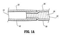
- FIG. 1Ais a partial cross-sectional view of the compression apparatus shown in FIG. 1 ;
- FIG. 2is a cutaway cross section view of a strap of the compression apparatus shown in FIG. 1 ;
- FIG. 3is a cutaway cross section view of an alternate embodiment of the strap of the compression apparatus shown in FIG. 1 ;
- FIG. 4is a plan view of an alternate embodiment of the compression apparatus shown in FIG. 1 , illustrating an inflatable bladder in phantom;
- FIG. 5is a plan view of another alternate embodiment of the compression apparatus shown in FIG. 1 , illustrating an inflatable bladder in phantom;
- FIG. 6is a plan view of another alternate embodiment of the compression apparatus shown in FIG. 1 , illustrating an inflatable bladder in phantom;
- FIG. 7is a plan view of another alternate embodiment of the compression apparatus shown in FIG. 1 , illustrating an inflatable bladder in phantom.
- the exemplary embodiments of the compression apparatus including the foot sleeve and methods of operation disclosedare discussed in terms of vascular therapy including a compression apparatus for application to a foot or other limb of a body and more particularly in terms of a compression apparatus configured to artificially stimulate the blood vessels of the limb including the foot, heel and toes of a patient. It is contemplated that the compression apparatus may be employed for preventing and overcoming the risks associated with patient immobility. It is further contemplated that the compression apparatus alleviates the conditions arising from patient immobility to prevent for example, DVT, and peripheral edema.
- the compression apparatusmay be employed with various types of venous compression systems, including, but not limited to rapid inflation, slow compression, non-sequential and sequential compression apparatus. It is envisioned that the present disclosure, however, finds application with a wide variety of immobile conditions of persons and patients alike, such as, for example, those undergoing surgery, anesthesia, extended periods of bed rest, obesity, advanced age, malignancy, and prior thromboembolism.
- the term “subject”refers to a patient undergoing vascular therapy using the compression apparatus.
- the following discussionincludes a description of the compression apparatus, followed by a description of an exemplary method of operating the compression apparatus in accordance with the principals of the present disclosure.
- Compression apparatus 10constructed in accordance with the principals of the present disclosure (see, for example, the compression sleeve described in U.S. patent application Ser. No. 10/784,607, filed on Feb. 23, 2004 and entitled Compression Apparatus, the entire contents of which is hereby incorporated by reference herein).
- Compression apparatus 10includes an expandable body, such as, for example, a foot sleeve 12 configured for disposal about a foot F of a subject (not shown). Foot sleeve 12 may be disposed with the right or left foot of the subject.
- Foot sleeve 12fluidly communicates with a pressurized fluid source 14 via tubing 16 and a valve connector 18 (see, for example, the valve connector described in U.S. patent application Ser. No. 10/784,639, filed on Feb. 23, 2004 and entitled Fluid Conduit Connector Apparatus, the entire contents of which is hereby incorporated by reference herein) for applying compression to the left foot and/or the right foot to provide vascular therapy to the subject and augment venous return.
- Compression apparatus 10employs a controller 20 to regulate fluid pressure for vascular therapy. See, for example, the controller described in U.S. patent application Ser. No. 10/784,323, filed on Feb. 23, 2004 and entitled Compression Treatment System, the entire contents of which is hereby incorporated by reference herein.
- Pressurized fluid source 14may include a pump and may be stationary or portable. It is contemplated that pressurized fluid source 14 may include the necessary electronics and computer software to carry out vascular therapy, in accordance with the principles of the present disclosure.
- Foot sleeve 12is configured to apply vascular therapy to the entire area of the bottom of foot F, beyond a heel H and a ball B to a substantial portion of toes T. It is contemplated that foot sleeve 12 and other parts of compression apparatus 10 may be disposed, wrapped and mounted with various limbs and extremities of a subject's body, such as, for example, legs and arms. It is further contemplated that foot sleeve 12 or portions thereof may be disposable. It is envisioned that foot sleeve 12 may include flexible sections, such as, elastic or spandex materials to facilitate mobility of a limb during use. The components of strap 22 may be fabricated from materials suitable for compression vascular therapy such as, for example, films and fabrics, such as PVC (polyvinyl chloride) and PE (polyethylene).
- PVCpolyvinyl chloride
- PEpolyethylene
- Strap 22is configured for disposal about foot F adjacent to the ankle. Strap 22 is integrally connected to foot sleeve 12 and fixedly mounted between a foot contact layer 26 and an outer layer 28 of foot sleeve 12 , as will be discussed. Strap 22 may be monolithically formed with foot sleeve 12 , wherein at least a portion of the strap 22 is formed from the same contiguous material as a portion of the foot sleeve 12 . By way of non-limiting example, foot contact layer 26 may be formed from the same contiguous material as foot contact layer 32 of foot sleeve 12 . Strap 22 has segmented portions 24 that are configured to contour about heel H of foot F. It is contemplated that segmented portions 24 may be variously configured and dimensioned, such as, rounded or alternatively, strap 22 may have a uniform outer surface, such as, smooth.
- Strap 22has a first layer, such as, for example, foot contact layer 26 that is configured to engage to an outer surface of foot F adjacent the ankle.
- Foot contact layer 26includes a soft polyester material 26 a that is soft for engaging the skin of the subject. This soft skin contact layer 26 advantageously provides comfort to the subject, prevents contamination and mitigates skin breakdown.
- Foot contact layer 26may also include a PVC portion 26 b disposed adjacent soft polyester material 26 a.
- a second layersuch as, for example, outer layer 28 cooperates with foot contact layer 26 such that a third layer 30 is disposed therebetween.
- Third layer 30includes a foam material to provide a cushioning effect to the subject. It is contemplated that layer 30 may include alternative materials that provide a cushioned configuration.
- Outer layer 28includes a loop type material 28 a disposed therewith, for engagement with a corresponding hook element of foot sleeve 12 , and a PVC portion 28 b disposed adjacent loop material 28 a. Outer layer 28 advantageously prevents contamination of third cushion layer 30 from the environment, such as, for example, air, moisture and dirt.
- Foot contact layer 26 and outer layer 28are configured to form a physical barrier to third cushion layer 30 .
- This configurationadvantageously provides comfort to the subject, as well as compliance, and prevents contamination of third cushioning layer 30 .
- strap 22includes a laminate structure having a cushion layer 130 and a PVC portion 132 disposed adjacent thereto.
- An outer layer 134is disposed adjacent PVC portion 132 .
- Layer 134may include a soft polyester material for engaging the outer surface of foot F, or alternatively, may include a loop material to prevent contamination of cushion layer 130 from the environment.
- Foot contact layer 26 and outer layer 28are overlaid to form strap 22 .
- Foot contact layer 26 and outer layer 28are fixedly joined at seams adjacent corresponding perimeters thereof, to support the components of strap 22 .
- the components of strap 22may be bonded via welding, e.g., RF welding, adhesive, industrial strength double sided tape and the like. It is envisioned that only a portion of the foot contact layer 26 and outer layer 28 are joined. It is further envisioned that strap 22 includes a plurality of seams, disposed variously thereabout, that join foot contact layer 26 and outer layer 28 .
- FIG. 1Aan exaggerated partial cross-sectional view of a strap member 22 and its union to foot sleeve 12 is shown.
- the strap member 22is disposed between the foot contact layer 32 and outer layer 42 of foot sleeve 12 such that the union of strap 22 and foot sleeve 12 is generally uniform. Such uniformity provides additional comfort to the user of the foot sleeve 12 .
- foot contact layer 26 and outer layer 28 of strap 22are joined to interior portions of foot contact layer 32 and outer layer 42 of foot sleeve 12 .
- cushioning layer 30may or may not be disposed between foot contact layer 32 and outer layer 42 of foot sleeve 12 .
- Strap 22has a longitudinally projecting configuration extending from foot sleeve 12 and is configured for disposal about portions of foot F adjacent the ankle. Strap 22 forms part of a hook and loop type connector.
- a hook element 33is mounted to strap 22 at foot contact layer 26 . As strap 22 is wrapped about the portions of foot F adjacent the ankle, hook element 33 engages the loop material of outer layer 42 of foot sleeve 12 to facilitate mounting of foot sleeve 12 with foot F.
- Alternative to hook and loop type elements, clips, adhesive and pinsmay be employed.
- Foot sleeve 12includes a foot contact layer 32 configured to engage foot F for applying pressure thereto.
- Foot contact layer 32has sections 35 and is flexible for conforming to the shape of foot F. It is envisioned that foot contact layer 32 may be fabricated from a polyester fabric. It is contemplated that foot contact layer 32 may be configured for wicking fluids such as, moisture and perspiration from an outer surface of foot F. Foot contact layer 32 may be treated chemically to enhance such wicking effect. Alternatively, foot contact layer 32 may be monolithically formed with foot contact layer 26 of strap 22 .
- An inflatable bladder 34 of foot sleeve 12includes an upper bladder layer 36 and a lower bladder layer 38 that are overlaid to form inflatable bladder 34 .
- Upper bladder layer 36engages foot contact layer 32 to facilitate application of pressure for vascular therapy to foot F.
- Upper bladder layer 36 and lower bladder layer 38are fixedly joined via welding at seams along their perimeters to define inflatable bladder 34 .
- inflatable bladder 34may include a plurality of seams, disposed variously thereabout, that join upper bladder layer 36 and lower bladder layer 38 . It is further contemplated that the seams may be formed by adhesive, heat sealed and the like.
- Upper bladder layer 36 and lower bladder layer 38may be fabricated from a laminated material, for example, a PVC material. It is contemplated that each bladder layer may have a thickness of approximately 6-15 mils. It is further contemplated that the PVC material may be laminated to a non-woven or woven material and is RF heat sealable. Upper bladder layer 36 and lower bladder layer 38 may be fabricated from two different thicknesses to provide directional inflation. It is envisioned that the overall dimensions and materials described throughout this disclosure are not limiting and that other dimensions and materials may be used. It is further envisioned that inflatable bladder 34 may define one or a plurality of expandable chambers.
- Inflatable bladder 34extends along foot F to apply vascular therapy to the entire area of the bottom of foot F, beyond heel H and ball B to a substantial portion of toes T. It is contemplated that inflatable bladder 34 may have various geometric configurations, such as, circular, elliptical and rectangular. Inflatable bladder 34 includes an inlet port 40 that connects to tubing 16 to facilitate fluid communication with pressurized fluid source 14 .
- Outer layer 42 of foot sleeve 12is disposed adjacent to lower bladder layer 38 .
- Outer layer 42may be fabricated from a laminated material including fabric and a loop material, for example, a loop/non-woven laminate. Outer layer 42 provides an attachment surface for hook elements. Alternatively, outer layer 42 may be monolithically formed with outer layer 28 of strap 22 .
- Outer layer 42may include die cut holes to provide for a fluid inlet to pass through, such as inlet port 40 . It is envisioned that outer layer 42 and other portions of foot sleeve 12 may include vent openings disposed variously thereabout to provide cooling to the subject and increase mobility during use.
- Foot contact layer 32 and outer layer 42are overlaid to form foot sleeve 12 .
- Foot contact layer 32 and outer layer 42are fixedly joined at seams adjacent corresponding perimeters thereof, to support the components of foot sleeve 12 .
- the components of foot sleeve 12may be bonded via welding, e.g., RF welding, adhesive, industrial strength double sided tape and the like. It is envisioned that only a portion of the perimeters of foot contact layer 32 and outer layer 42 are joined. It is envisioned that foot sleeve 12 includes a plurality of seams, disposed variously thereabout, that join foot contact layer 32 and outer layer 42 .
- foot sleeve 12may be fabricated from materials suitable for compression vascular therapy such as, for example, films and fabrics, such as PVC (polyvinyl chloride) and PE (polyethylene), depending on the particular vascular therapy application and/or preference. Semi-flexible and flexible fabrics, such as urethanes and silicones may also be used. Moreover, foot sleeve 12 may be fabricated from synthetic, natural, and non-woven materials of varying degrees of softness and pliability. One skilled in the art, however, will realize that other materials and fabrication methods suitable for assembly and manufacture, in accordance with the present disclosure, also would be appropriate.
- Foot sleeve 12is configured to support inflatable bladder 34 .
- Foot sleeve 12extends laterally and is configured for disposal about foot F and mounting thereto.
- Foot sleeve 12is disposed with foot F such that the top portion of toes T are visible for observation and inspection.
- a metatarsal flap 44 of foot sleeve 12wraps about the side portions of foot F and transverses the instep of foot F during vascular therapy. Metatarsal flap 44 forms part of a hook and loop type connector.
- a hook element 46is mounted to foot sleeve 12 at foot contact layer 32 . As metatarsal flap 44 is wrapped about foot F, hook element 46 engages the loop material of outer layer 42 to facilitate mounting of foot sleeve 12 with foot F.
- foot sleeve 12advantageously engages foot F to augment circulation of vessels of the limb. It is contemplated that foot sleeve 12 may have various geometric configurations, such as, circular, elliptical, and rectangular. Alternative to hook and loop type elements, clips, adhesive, and pins may be employed.
- Compression apparatus 10is assembled and packaged for use.
- foot sleeve 12 of compression apparatus 10is disposed about foot F and in fluid communication with pressurized fluid source 14 , as discussed.
- Controller 20regulates vascular therapy of compression apparatus 10 to a subject.
- Foot sleeve 12applies compression to foot F to provide vascular therapy to the subject and augment venous return.
- compression apparatus 10may include inflatable sleeves for disposal about various portions of a subject's limb, such as for example, thigh, calf, ankle and that a second limb may be treated in alternate compression cycles with other sleeve(s).
- inflatable bladder 34is slowly inflated for 5 seconds with air to a pressure, such as 130 mm Hg.
- a pressuresuch as 130 mm Hg.
- This configurationprovides vascular therapy to foot F and augments venous return.
- foot sleeve 12is vented and inflatable bladder 34 is deflated.
- Other compression cycles and pressuresare also contemplated.
- VRTVenous refill time
- compression apparatus 10performs venous refill time measurement.
- Venous refill time (VRT) measurementis an air plethysmographic technique that determines when the veins of a limb have completely refilled with blood following a compression cycle. See, for example, the venous refill time measurement described in U.S. Pat. No. 6,231,352 to Watson et al., the entire contents of which is hereby incorporated by reference herein.
- the VRTminimizes the amount of time that the blood remains stagnant inside the veins.
- the VRTis substituted for the default rest time between compression cycles. It is contemplated that the VRT technique and algorithm can be used for both leg sleeve and foot sleeve compression.
- the VRT measurementuses an air plethysmographic technique where a low pressure is applied to inflatable bladder 34 . As the veins fill with blood, the pressure in inflatable bladder 34 increases until a plateau is reached. The time that it takes for the pressure to plateau is the VRT. If two sleeves are connected to controller 20 , then the VRT is determined separately for each limb being compressed and the greater of the two measurements is used as the new vent time of the compression cycle. The VRT measurement for each sleeve is made as each particular sleeve reaches set pressure independently. However, the vent time is not updated until VRT measurements have been calculated for both sleeves.
- compression apparatus 10may employ the VRT measurement after the system initiates vascular therapy. Subsequently, after 30 minutes have elapsed, a VRT measurement will be taken on the next full inflation cycle. After foot sleeve 12 inflates, inflatable bladder 34 is vented down to zero.
- a selected bladder pressureis monitored and the vent to the bladder is closed when the pressure falls to 5-7 mm Hg. If the pressure in the bladder is 5-7 mm Hg on a current cycle then a VRT measurement is taken. If the pressure in the bladder does not vent down to 5-7 mm Hg then the vent time will remain at its current value and another measurement will be made in 30 minutes.
- the VRT measurement algorithmdetermines when the pressure in inflatable bladder 34 plateaus after compression.
- the VRT measurement algorithminitiates with a time counter started from the end of the inflation cycle, which occurs after inflatable bladder 34 reaches 5-7 mm Hg (enough pressure to cause the bladder to remain in contact with the surface of the foot) and the venting is stopped.
- the VRT measurementinitiates with the time counter started from the end of the inflation cycle.
- the pressure in inflatable bladder 34is then monitored with a 10-second, moving sample window.
- the windowmoves in 1-second intervals.
- the difference between the first and last values in the windowis less than approximately 0.05-0.5 mm Hg, the curve has reached its plateau.
- the VRT measurementis considered done, and the time interval is determined.
- the end of the windowis considered to be the point at which the venous system in the foot has refilled.
- the VRT measurementis considered erroneous if at any time during the measurement, the pressure in inflatable bladder 34 is below 2 mmHg, the calculation is discarded, and the old value of VRT is used. This may occur if there is a leak in the system. It is contemplated that if the pressure is greater than 20 mmHg at any time during the VRT measurement, the old value of the VRT is used.
- Compression apparatus 10includes a foot sleeve 212 , similar to foot sleeve 12 described above with regard to FIGS. 1 , 1 A and 2 , configured for disposal about foot F.
- a pair of straps 222similar to strap 22 described above with regard to FIGS. 1 , 1 A and 2 , extend from foot sleeve 212 . Straps 222 are configured for disposal about foot F adjacent to the ankle. One or a plurality of straps 222 may be employed.
- Straps 222have a longitudinally projecting configuration extending from foot sleeve 212 and are configured for disposal about portions of foot F adjacent the ankle. As discussed herein, it is contemplated that straps 222 may be separately or monolithically formed with foot sleeve 212 . Straps 222 form part of hook and loop type connectors. Hook element 232 and loop element 232 a are mounted to straps 222 . As each of straps 222 are wrapped about the portions of foot F adjacent the ankle, hook element 232 engages loop material 232 a to facilitate mounting of foot sleeve 212 with foot F. It is contemplated that hook elements 232 , 232 a may engage loop material disposed with an outer surface of foot sleeve 212 to facilitate mounting of foot sleeve 212 with foot F.
- An inflatable bladder 234extends longitudinally along foot F to apply vascular therapy to the entire area of the bottom of foot F, beyond heel H and ball B to a substantial portion of toes T.
- Inflatable bladder 234includes an inlet port 240 that connects to tubing 16 to facilitate fluid communication with pressurized fluid source 14 .
- Foot sleeve 212is configured to support inflatable bladder 234 . Foot sleeve 212 extends laterally and is configured for disposal about foot F and mounting thereto. Foot sleeve 212 is disposed with foot F such that the top portion of toes T are visible for observation and inspection.
- a pair of metatarsal flaps 244extend laterally from foot sleeve 212 for wrapping about the side portions of foot F and transversing the instep of foot F during vascular therapy. Metatarsal flaps 244 form the hook and loop type connectors. Hook element 246 and loop element 246 a are mounted to foot sleeve 212 .
- foot sleeve 212As metatarsal flaps 244 are wrapped about foot F, hook element 246 engages to loop element 246 a to engage the foot sleeve 212 to facilitate mounting of foot sleeve 212 with foot F. In turn, this causes inflatable bladder 234 to be disposed about foot F for vascular therapy.
- This configuration of foot sleeve 212advantageously engages foot F to augment circulation of vessels of the limb.
- Foot sleeve 212includes vent openings 250 disposed to provide cooling to the subject and increase mobility during use.
- Compression apparatus 10includes a foot sleeve 312 , similar to those described above, configured for disposal about foot F.
- a strap 322similar to those described above, extends from foot sleeve 312 .
- An inflatable bladder 334similar to those described above, extends longitudinally along foot F to apply vascular therapy to the entire area of the bottom of foot F, beyond heel H and ball B to a substantial portion of toes T.
- Inflatable bladder 334includes side portions 336 that extend laterally therefrom to engage side portions of foot F during application of foot sleeve 312 with foot F.
- Foot sleeve 312is configured to support inflatable bladder 334 . Foot sleeve 312 extends laterally and is configured for disposal about foot F and mounting thereto. Foot sleeve 312 is disposed with foot F such that the top portion of toes T are visible for observation and inspection.
- a pair of metatarsal flaps 344extend laterally from one side of foot sleeve 312 for wrapping about the side portions of foot F and transversing the instep of foot F during vascular therapy. Metatarsal flaps 344 form part of hook and loop type connectors. Hook elements 346 , 346 a are mounted to foot sleeve 312 .
- hook elements 346 , 346 aengage the loop material of foot sleeve 312 to facilitate mounting of foot sleeve 312 with foot F.
- thiscauses inflatable bladder 334 to be disposed about foot F, including side portions 336 engaging the side portions of foot F, for vascular therapy.
- This configuration of foot sleeve 312advantageously engages foot F to augment circulation of vessels of the limb.
- Compression apparatus 10includes a foot sleeve 412 , similar to those described above, configured for disposal about foot F.
- a strap 422similar to those described above, extends from foot sleeve 412 .
- An inflatable bladder 434similar to those described above, extends longitudinally along foot F to apply vascular therapy to the bottom of foot F, beyond heel H and ball B to a substantial portion of toes T.
- Foot sleeve 412has wings 444 (similar to metatarsal flaps described above) and is configured to support inflatable bladder 434 . Foot sleeve 412 extends laterally, via wings 444 , and is configured for disposal about foot F and mounting thereto. Foot sleeve 412 is disposed with foot F such that the top portion of toes T are visible for observation and inspection. Wings 444 wrap about the side portions of foot F and transverse the instep of foot F during vascular therapy. Wings 444 form part of hook and loop type connectors. Hook element 446 and loop element 446 a are mounted to wings 444 .
- hook element 446engages with loop element 446 a to facilitate mounting of foot sleeve 412 with foot F.
- thiscauses inflatable bladder 434 to be disposed about foot F for vascular therapy.
- This configuration of foot sleeve 412advantageously engages foot F to augment circulation of vessels of the limb.
- Compression apparatus 10includes a foot sleeve 512 , similar to those described above, configured for disposal about foot F.
- a strap 522similar to those described above, extends from foot sleeve 512 .
- An inflatable bladder 534similar to those described above, extends longitudinally along foot F to apply vascular therapy to the bottom of foot F, beyond heel H and ball B to a substantial portion of toes T.
- Inflatable bladder 534includes longitudinal portions 536 that extend longitudinally therefrom to engage desired portions of the bottom of foot F during application of foot sleeve 512 with foot F.
- Foot sleeve 512is configured to support inflatable bladder 534 . This configuration of foot sleeve 512 advantageously engages foot F to augment circulation of vessels of the limb.
Landscapes
- Health & Medical Sciences (AREA)
- Animal Behavior & Ethology (AREA)
- Veterinary Medicine (AREA)
- Public Health (AREA)
- General Health & Medical Sciences (AREA)
- Life Sciences & Earth Sciences (AREA)
- Rehabilitation Therapy (AREA)
- Physical Education & Sports Medicine (AREA)
- Pain & Pain Management (AREA)
- Epidemiology (AREA)
- Engineering & Computer Science (AREA)
- Biomedical Technology (AREA)
- Heart & Thoracic Surgery (AREA)
- Vascular Medicine (AREA)
- Massaging Devices (AREA)
- Orthopedics, Nursing, And Contraception (AREA)
Abstract
Description
Claims (7)
Priority Applications (54)
| Application Number | Priority Date | Filing Date | Title |
|---|---|---|---|
| US10/784,604US7282038B2 (en) | 2004-02-23 | 2004-02-23 | Compression apparatus |
| ES05723526TES2378886T3 (en) | 2004-02-23 | 2005-02-23 | Compression apparatus |
| EP05713934AEP1718894B1 (en) | 2004-02-23 | 2005-02-23 | Fluid conduit connector apparatus |
| AU2005216923AAU2005216923B2 (en) | 2004-02-23 | 2005-02-23 | Compression treatment system |
| EP10185260.6AEP2314268B1 (en) | 2004-02-23 | 2005-02-23 | Compression treatment system |
| PL05713935TPL1720504T3 (en) | 2004-02-23 | 2005-02-23 | Compression apparatus |
| KR1020067016843AKR20070001964A (en) | 2004-02-23 | 2005-02-23 | Compression device |
| DE602005022165TDE602005022165D1 (en) | 2004-02-23 | 2005-02-23 | Fluidleitungsverbindervorrichtung |
| CN2005800043487ACN1918422B (en) | 2004-02-23 | 2005-02-23 | Fluid Pipe Connections |
| AU2005216924AAU2005216924B2 (en) | 2004-02-23 | 2005-02-23 | Compression apparatus |
| DE602005021460TDE602005021460D1 (en) | 2004-02-23 | 2005-02-23 | COMPRESSION UNIT |
| KR1020067016796AKR100914569B1 (en) | 2004-02-23 | 2005-02-23 | Compression treatment system |
| CN201210098027.XACN102614074B (en) | 2004-02-23 | 2005-02-23 | Compression therapeutic apparatus |
| CNA2005800043491ACN1917844A (en) | 2004-02-23 | 2005-02-23 | Compression apparatus |
| PCT/US2005/005599WO2005083313A1 (en) | 2004-02-23 | 2005-02-23 | Fluid conduit connector apparatus |
| ES10185260TES2806930T3 (en) | 2004-02-23 | 2005-02-23 | Compression treatment system |
| EP05713933.9AEP1722738B1 (en) | 2004-02-23 | 2005-02-23 | Compression treatment system |
| EP05713935AEP1720504B1 (en) | 2004-02-23 | 2005-02-23 | Compression apparatus |
| HK06113291.3AHK1091390B (en) | 2004-02-23 | 2005-02-23 | Compression apparatus |
| JP2006554296AJP4571156B2 (en) | 2004-02-23 | 2005-02-23 | Compression treatment system |
| ES05713935TES2346546T3 (en) | 2004-02-23 | 2005-02-23 | COMPRESSION APPARATUS |
| DK05713935.4TDK1720504T3 (en) | 2004-02-23 | 2005-02-23 | compression apparatus |
| CA002552355ACA2552355C (en) | 2004-02-23 | 2005-02-23 | Compression apparatus |
| AT05713935TATE468834T1 (en) | 2004-02-23 | 2005-02-23 | COMPRESSION DEVICE |
| AU2005217424AAU2005217424B2 (en) | 2004-02-23 | 2005-02-23 | Fluid conduit connector apparatus |
| CN2005800043260ACN1917842B (en) | 2004-02-23 | 2005-02-23 | compression therapy system |
| AT05723526TATE536851T1 (en) | 2004-02-23 | 2005-02-23 | COMPRESSION DEVICE |
| PCT/US2005/005600WO2005082315A1 (en) | 2004-02-23 | 2005-02-23 | Compression apparatus |
| PCT/US2005/005679WO2005082316A2 (en) | 2004-02-23 | 2005-02-23 | Compression apparatus |
| ES05713933TES2414880T3 (en) | 2004-02-23 | 2005-02-23 | Compression treatment system |
| AT05713934TATE473390T1 (en) | 2004-02-23 | 2005-02-23 | FLUID LINE CONNECTOR DEVICE |
| CN2005800043472ACN1917843B (en) | 2004-02-23 | 2005-02-23 | Compression apparatus |
| CA2552354ACA2552354C (en) | 2004-02-23 | 2005-02-23 | Fluid conduit connector apparatus |
| JP2006554297AJP4602996B2 (en) | 2004-02-23 | 2005-02-23 | Fluid conduit connector device |
| AU2005216934AAU2005216934B2 (en) | 2004-02-23 | 2005-02-23 | Compression apparatus |
| EP10185262.2AEP2319476A3 (en) | 2004-02-23 | 2005-02-23 | Compression treatment system |
| CA002552331ACA2552331C (en) | 2004-02-23 | 2005-02-23 | Compression apparatus |
| KR1020067016842AKR100868148B1 (en) | 2004-02-23 | 2005-02-23 | Fluid connecttor apparatus |
| KR1020067016795AKR100873540B1 (en) | 2004-02-23 | 2005-02-23 | Compression apparatus |
| CA002552353ACA2552353C (en) | 2004-02-23 | 2005-02-23 | Compression treatment system |
| JP2006554298AJP4686485B2 (en) | 2004-02-23 | 2005-02-23 | Compression device |
| EP05723526AEP1720505B1 (en) | 2004-02-23 | 2005-02-23 | Compression apparatus |
| PCT/US2005/005598WO2005082314A1 (en) | 2004-02-23 | 2005-02-23 | Compression treatment system |
| KR1020087023566AKR100918718B1 (en) | 2004-02-23 | 2005-02-23 | Compression apparatus |
| PL05723526TPL1720505T3 (en) | 2004-02-23 | 2005-02-23 | Compression apparatus |
| JP2006554310AJP2007522892A (en) | 2004-02-23 | 2005-02-23 | Compression device |
| IL176410AIL176410A (en) | 2004-02-23 | 2006-06-19 | Compression treatment system |
| IL176409AIL176409A (en) | 2004-02-23 | 2006-06-19 | Compression apparatus |
| IL176433AIL176433A (en) | 2004-02-23 | 2006-06-20 | Fluid connector apparatus |
| IL176432AIL176432A0 (en) | 2004-02-23 | 2006-06-20 | Compression apparatus |
| NO20064256ANO20064256L (en) | 2004-02-23 | 2006-09-20 | Fluidrorkonnektoranordning |
| NO20064255ANO20064255L (en) | 2004-02-23 | 2006-09-20 | A printing system |
| NO20064281ANO20064281L (en) | 2004-02-23 | 2006-09-21 | A printing system |
| NO20064310ANO20064310L (en) | 2004-02-23 | 2006-09-22 | Pressure Treatment System |
Applications Claiming Priority (1)
| Application Number | Priority Date | Filing Date | Title |
|---|---|---|---|
| US10/784,604US7282038B2 (en) | 2004-02-23 | 2004-02-23 | Compression apparatus |
Publications (2)
| Publication Number | Publication Date |
|---|---|
| US20050187499A1 US20050187499A1 (en) | 2005-08-25 |
| US7282038B2true US7282038B2 (en) | 2007-10-16 |
Family
ID=34861488
Family Applications (1)
| Application Number | Title | Priority Date | Filing Date |
|---|---|---|---|
| US10/784,604Expired - LifetimeUS7282038B2 (en) | 2004-02-23 | 2004-02-23 | Compression apparatus |
Country Status (2)
| Country | Link |
|---|---|
| US (1) | US7282038B2 (en) |
| CN (1) | CN1917844A (en) |
Cited By (44)
| Publication number | Priority date | Publication date | Assignee | Title |
|---|---|---|---|---|
| US20080249444A1 (en)* | 2007-04-09 | 2008-10-09 | Tyco Healthcare Group Lp | Compression Device with Structural Support Features |
| USD579116S1 (en)* | 2007-07-27 | 2008-10-21 | Tyco Healthcare Group Lp | Foot cuff with tapered, blunt end |
| US20090062703A1 (en)* | 2005-12-12 | 2009-03-05 | Tyco Healthcare Group Lp | Compression Sleeve Having Air Conduits |
| US20090076424A1 (en)* | 2004-12-17 | 2009-03-19 | Osim International Ltd. | Pneumatic Massaging Device |
| USD608006S1 (en) | 2007-04-09 | 2010-01-12 | Tyco Healthcare Group Lp | Compression device |
| US20100010398A1 (en)* | 2008-07-08 | 2010-01-14 | Leap Frogg, Llc | Foot compression system |
| US20100049107A1 (en)* | 2002-08-02 | 2010-02-25 | Gordon Cook | Inflatable device for use in impulse therapy |
| USD618358S1 (en) | 2007-04-09 | 2010-06-22 | Tyco Healthcare Group Lp | Opening in an inflatable member for a pneumatic compression device |
| US20100249679A1 (en)* | 2004-02-23 | 2010-09-30 | Tyco Healthcare Group Lp | Garment Detection Method and System for Delivering Compression Treatment |
| US7871387B2 (en) | 2004-02-23 | 2011-01-18 | Tyco Healthcare Group Lp | Compression sleeve convertible in length |
| US7880050B2 (en) | 2007-02-09 | 2011-02-01 | Kci Licensing, Inc. | Breathable interface system for topical reduced pressure |
| US7931606B2 (en) | 2005-12-12 | 2011-04-26 | Tyco Healthcare Group Lp | Compression apparatus |
| US20110214315A1 (en)* | 2010-03-05 | 2011-09-08 | Leap Frogg, Llc | Therapy shoe |
| US8016779B2 (en) | 2007-04-09 | 2011-09-13 | Tyco Healthcare Group Lp | Compression device having cooling capability |
| US8021388B2 (en) | 2007-04-09 | 2011-09-20 | Tyco Healthcare Group Lp | Compression device with improved moisture evaporation |
| US8029450B2 (en) | 2007-04-09 | 2011-10-04 | Tyco Healthcare Group Lp | Breathable compression device |
| US8070699B2 (en) | 2007-04-09 | 2011-12-06 | Tyco Healthcare Group Lp | Method of making compression sleeve with structural support features |
| US8109892B2 (en) | 2007-04-09 | 2012-02-07 | Tyco Healthcare Group Lp | Methods of making compression device with improved evaporation |
| US8114117B2 (en) | 2008-09-30 | 2012-02-14 | Tyco Healthcare Group Lp | Compression device with wear area |
| US8128584B2 (en) | 2007-04-09 | 2012-03-06 | Tyco Healthcare Group Lp | Compression device with S-shaped bladder |
| US8158844B2 (en) | 2008-10-08 | 2012-04-17 | Kci Licensing, Inc. | Limited-access, reduced-pressure systems and methods |
| US8162861B2 (en) | 2007-04-09 | 2012-04-24 | Tyco Healthcare Group Lp | Compression device with strategic weld construction |
| US8235923B2 (en) | 2008-09-30 | 2012-08-07 | Tyco Healthcare Group Lp | Compression device with removable portion |
| US8377017B2 (en) | 2008-01-03 | 2013-02-19 | Kci Licensing, Inc. | Low-profile reduced pressure treatment system |
| US8444611B2 (en)* | 2003-07-22 | 2013-05-21 | Kci Licensing, Inc. | Negative pressure wound treatment dressing |
| US8506508B2 (en) | 2007-04-09 | 2013-08-13 | Covidien Lp | Compression device having weld seam moisture transfer |
| US8539647B2 (en) | 2005-07-26 | 2013-09-24 | Covidien Ag | Limited durability fastening for a garment |
| US8613762B2 (en) | 2010-12-20 | 2013-12-24 | Medical Technology Inc. | Cold therapy apparatus using heat exchanger |
| US8636678B2 (en) | 2008-07-01 | 2014-01-28 | Covidien Lp | Inflatable member for compression foot cuff |
| US8652079B2 (en) | 2010-04-02 | 2014-02-18 | Covidien Lp | Compression garment having an extension |
| US8979915B2 (en) | 2010-04-19 | 2015-03-17 | Pulsar Scientific, LLC | Separable system for applying compression and thermal treatment |
| US9114055B2 (en) | 2012-03-13 | 2015-08-25 | Cothera Llc | Deep vein thrombosis (“DVT”) and thermal/compression therapy systems, apparatuses and methods |
| US9125787B2 (en) | 2011-09-30 | 2015-09-08 | Covidien Lp | Compression garment having a foam layer |
| US9205021B2 (en) | 2012-06-18 | 2015-12-08 | Covidien Lp | Compression system with vent cooling feature |
| USD752695S1 (en)* | 2015-03-23 | 2016-03-29 | Ilya Boruch | Grip assist cuff with pad |
| US9402779B2 (en) | 2013-03-11 | 2016-08-02 | Covidien Lp | Compression garment with perspiration relief |
| US9402763B2 (en) | 2012-09-12 | 2016-08-02 | Breg, Inc. | Cold therapy apparatus having heat exchanging therapy pad |
| US9439828B2 (en) | 2008-07-08 | 2016-09-13 | Avex, L.L.C. | Foot compression system |
| US9566187B2 (en) | 2012-03-13 | 2017-02-14 | Breg, Inc. | Cold therapy systems and methods |
| USD790070S1 (en)* | 2015-02-19 | 2017-06-20 | Huntleigh Technology Limited | Pump for use with compression garments |
| US9757302B2 (en) | 2011-08-12 | 2017-09-12 | Avex, Llc | Foot compression and electrical stimulation system |
| US10369075B2 (en) | 2015-03-03 | 2019-08-06 | Avex, Llc | Insole foot compression system and methods |
| US10751221B2 (en) | 2010-09-14 | 2020-08-25 | Kpr U.S., Llc | Compression sleeve with improved position retention |
| US10799415B2 (en) | 2011-12-02 | 2020-10-13 | Avex, Llc | Spring-driven foot compression system |
Families Citing this family (7)
| Publication number | Priority date | Publication date | Assignee | Title |
|---|---|---|---|---|
| US7896825B2 (en)* | 2005-06-17 | 2011-03-01 | Bridgepoint Medical, Inc. | Medical compression devices and methods |
| US8257286B2 (en) | 2006-09-21 | 2012-09-04 | Tyco Healthcare Group Lp | Safety connector apparatus |
| US20080249559A1 (en)* | 2007-04-09 | 2008-10-09 | Tyco Healthcare Group Lp | Compression device with improved moisture evaporation |
| US8092409B2 (en) | 2007-05-18 | 2012-01-10 | Tyco Healthcare Group Lp | Reinforced connector |
| US9713563B2 (en)* | 2013-03-15 | 2017-07-25 | Compression Therapy Concepts, Inc. | Micro bleed hole connector for use in intermittent pneumatic compression devices |
| NL2023185B1 (en)* | 2019-05-24 | 2020-12-02 | Tobrox Holding B V | COMPRESSION SOCK WITH ADJUSTABLE COMPRESSION PRESSURE |
| IT201900025837A1 (en)* | 2019-12-31 | 2021-07-01 | Francesco Facchiano | WEARABLE LYMPH DRAINING DEVICE |
Citations (135)
| Publication number | Priority date | Publication date | Assignee | Title |
|---|---|---|---|---|
| US1608239A (en) | 1925-12-09 | 1926-11-23 | Rosett Joshua | Therapeutic device |
| US2694395A (en) | 1951-05-10 | 1954-11-16 | William J Brown | Pneumatic pressure garment |
| US3164152A (en) | 1962-02-05 | 1965-01-05 | Nicoll Esmond D Vere | Inflatable splint |
| US3245405A (en) | 1962-11-26 | 1966-04-12 | William J Gardner | Inflatable therapeutic device and method of making same |
| US3454010A (en) | 1967-05-08 | 1969-07-08 | Robert W Lilligren | Surgical bandage,constrictive device,and inflatable means |
| US3561435A (en) | 1968-11-15 | 1971-02-09 | Dev Inc | Combined splint and coolant container |
| US3728875A (en) | 1971-01-07 | 1973-04-24 | Kendall & Co | Stocking with soft inner thigh area |
| US3786805A (en) | 1970-10-06 | 1974-01-22 | Inst Europ De Rech Et D Applic | Splint having inflatable detachable cushions |
| US3826249A (en) | 1973-01-30 | 1974-07-30 | A Lee | Leg constricting apparatus |
| US3877426A (en) | 1973-03-27 | 1975-04-15 | Robert P Nirschl | Muscular support |
| US3901221A (en) | 1974-04-08 | 1975-08-26 | Clinical Technology Internatio | Pressure cycle for stimulating blood circulation in the limbs |
| US3920006A (en) | 1974-01-02 | 1975-11-18 | Roy Lapidus Inc | Inflatable device for healing of tissue |
| US4013069A (en) | 1975-10-28 | 1977-03-22 | The Kendall Company | Sequential intermittent compression device |
| US4029087A (en) | 1975-10-28 | 1977-06-14 | The Kendall Company | Extremity compression device |
| US4030488A (en) | 1975-10-28 | 1977-06-21 | The Kendall Company | Intermittent compression device |
| US4066084A (en) | 1974-01-14 | 1978-01-03 | Hans Tillander | Blood emptying device |
| US4091804A (en) | 1976-12-10 | 1978-05-30 | The Kendall Company | Compression sleeve |
| US4156425A (en) | 1977-08-10 | 1979-05-29 | The Kendall Company | Protective compression sleeve |
| US4198961A (en) | 1979-01-12 | 1980-04-22 | The Kendall Company | Compression device with sleeve retained conduits |
| US4202312A (en) | 1977-03-17 | 1980-05-13 | Toyota Jidosha Kogyo Kabushiki Kaisha | Ignition device for rotary piston engine |
| US4202325A (en) | 1979-01-12 | 1980-05-13 | The Kendall Company | Compression device with improved fastening sleeve |
| US4206751A (en) | 1978-03-31 | 1980-06-10 | Minnesota Mining And Manufacturing Company | Intermittent compression device |
| US4207876A (en) | 1979-01-12 | 1980-06-17 | The Kendall Company | Compression device with ventilated sleeve |
| US4207875A (en) | 1979-01-12 | 1980-06-17 | The Kendall Company | Compression device with knee accommodating sleeve |
| US4253449A (en) | 1979-08-09 | 1981-03-03 | The Kendall Company | Compression device with connection system |
| US4280485A (en) | 1980-04-11 | 1981-07-28 | The Kendall Company | Compression device with simulator |
| US4320746A (en) | 1979-12-07 | 1982-03-23 | The Kendall Company | Compression device with improved pressure control |
| US4355632A (en) | 1980-08-06 | 1982-10-26 | Jobst Institute, Inc. | Anti-shock pressure garment |
| US4375217A (en) | 1980-06-04 | 1983-03-01 | The Kendall Company | Compression device with pressure determination |
| US4408599A (en) | 1981-08-03 | 1983-10-11 | Jobst Institute, Inc. | Apparatus for pneumatically controlling a dynamic pressure wave device |
| US4442834A (en) | 1981-10-02 | 1984-04-17 | Jobst Institute, Inc. | Pneumatic splint |
| US4453538A (en) | 1977-04-07 | 1984-06-12 | Whitney John K | Medical apparatus |
| US4531516A (en) | 1983-02-07 | 1985-07-30 | David Clark Company Incorporated | Transparent pressure garment |
| US4580816A (en) | 1984-01-25 | 1986-04-08 | E. R. Squibb & Sons, Inc. | Quick disconnect tube coupling |
| US4597384A (en) | 1984-06-29 | 1986-07-01 | Gaymar Industries, Inc. | Sequential compression sleeve |
| US4614179A (en) | 1985-08-08 | 1986-09-30 | Electro-Biology, Inc. | Medical appliance |
| US4614180A (en) | 1984-06-18 | 1986-09-30 | Electro-Biology, Inc. | Medical appliance |
| US4624248A (en) | 1983-02-07 | 1986-11-25 | David Clark Company Incorporated | Transparent pressure garment |
| US4696289A (en) | 1983-06-22 | 1987-09-29 | Electro-Biology, Inc. | Method of promoting venous pump action |
| US4702232A (en) | 1985-10-15 | 1987-10-27 | Electro-Biology, Inc. | Method and apparatus for inducing venous-return flow |
| US4721101A (en) | 1984-06-18 | 1988-01-26 | Electro-Biology, Inc. | Medical appliance |
| US4722332A (en) | 1984-01-30 | 1988-02-02 | Saggers Michael J | Inflatable garment for intermittent compression therapy |
| US4730606A (en) | 1986-01-22 | 1988-03-15 | Kinetic Concepts, Inc. | Apparatus for applying traction during oscillatory therapy |
| US4762121A (en) | 1981-08-14 | 1988-08-09 | Mego Afek, Industrial Measuring Instruments | Massaging sleeve for body limbs |
| US4827912A (en) | 1987-09-18 | 1989-05-09 | The Kendall Company | Multi-chamber porting device |
| USRE32940E (en) | 1983-06-22 | 1989-06-06 | Electro-Biology, Inc. | Medical appliance |
| USD302301S (en) | 1987-01-15 | 1989-07-18 | Aspen Laboratories, Inc. | Tourniquet cuff |
| US4883073A (en) | 1989-07-03 | 1989-11-28 | Farooq Aziz | Remedial device for treatment of carpal tunnel syndrome |
| US4938208A (en) | 1989-03-16 | 1990-07-03 | The Kendall Company | Full length compressible sleeve |
| US5007411A (en) | 1989-04-12 | 1991-04-16 | The Kendall Company | Device for applying compressive pressures against a patient's limb |
| US5014681A (en) | 1989-05-05 | 1991-05-14 | Mego Afek Industrial Measuring Instruments | Method and apparatus for applying intermittent compression to a body part |
| US5022387A (en) | 1987-09-08 | 1991-06-11 | The Kendall Company | Antiembolism stocking used in combination with an intermittent pneumatic compression device |
| US5031604A (en) | 1989-04-12 | 1991-07-16 | The Kendall Company | Device for applying compressive pressures to a patient's limb |
| US5062414A (en) | 1989-02-08 | 1991-11-05 | Royce Medical Company | Simplified orthopaedic back support |
| US5186163A (en) | 1991-11-25 | 1993-02-16 | The Kendall Company | Compression device |
| US5230335A (en) | 1991-01-23 | 1993-07-27 | Aircast, Inc. | Thermal compress system |
| US5263473A (en) | 1990-11-05 | 1993-11-23 | The Kendall Company | Compression device for the limb |
| US5277695A (en) | 1991-11-08 | 1994-01-11 | Aircast, Inc. | Adjustable ankle compress |
| US5314455A (en) | 1991-01-23 | 1994-05-24 | Aircast, Inc. | Thermal compress system |
| US5354260A (en) | 1993-05-13 | 1994-10-11 | Novamedix, Ltd. | Slipper with an inflatable foot pump |
| US5383894A (en) | 1993-07-30 | 1995-01-24 | The Kendall Co. | Compression device having stepper motor controlled valves |
| US5389065A (en) | 1993-06-15 | 1995-02-14 | Aircast, Inc. | Ankle brace with ATF compression |
| US5413142A (en) | 1992-10-29 | 1995-05-09 | Aircast, Inc. | Automatic fluid circulating system and method |
| USD358216S (en) | 1993-09-16 | 1995-05-09 | The Kendall Company | Sleeve for applying compressive pressure to the leg |
| US5435009A (en) | 1992-10-01 | 1995-07-25 | Huntleigh Technology Plc | Inflatable compression garment |
| US5437610A (en) | 1994-01-10 | 1995-08-01 | Spinal Cord Society | Extremity pump apparatus |
| US5466250A (en) | 1991-01-23 | 1995-11-14 | Aircast, Inc. | Automatic fluid compress and circulating system |
| US5478119A (en) | 1993-09-16 | 1995-12-26 | The Kendall Company | Polarized manifold connection device |
| US5489259A (en) | 1993-10-27 | 1996-02-06 | Sundance Enterprises, Inc. | Pressure-normalizing single-chambered static pressure device for supporting and protecting a body extremity |
| US5489252A (en) | 1994-04-11 | 1996-02-06 | Reynolds Consumer Products Inc. | Closure arrangement having a peelable seal |
| US5496262A (en) | 1994-01-06 | 1996-03-05 | Aircast, Inc. | Therapeutic intermittent compression system with inflatable compartments of differing pressure from a single source |
| US5514081A (en) | 1994-10-07 | 1996-05-07 | D'mannco, Inc. | Elbow orthosis having an inflatable bladder support and method of use |
| US5575762A (en) | 1994-04-05 | 1996-11-19 | Beiersdorf-Jobst, Inc. | Gradient sequential compression system and method for reducing the occurrence of deep vein thrombosis |
| USD376013S (en) | 1994-04-05 | 1996-11-26 | Beiersdorf-Jobst, Inc. | Compression sleeve for deep vein thrombosis |
| US5584798A (en) | 1992-11-23 | 1996-12-17 | Novamedix Limited | Medical inflatable cuff appliance |
| US5588955A (en) | 1993-07-08 | 1996-12-31 | Aircast, Inc. | Method and apparatus for providing therapeutic compression for reducing risk of DVT |
| US5591200A (en) | 1994-06-17 | 1997-01-07 | World, Inc. | Method and apparatus for applying pressure to a body limb for treating edema |
| US5626556A (en) | 1994-07-26 | 1997-05-06 | The Kendall Company | Hook and loop attachment for a compression sleeve and method of attaching a hook and loop fastener to a compression sleeve |
| US5634889A (en) | 1993-01-18 | 1997-06-03 | Novamedix Limited | Medical appliance for intermittently pulsed compression of proximal joints and adjacent tissue of the human body |
| US5653244A (en) | 1996-06-04 | 1997-08-05 | Circaid Medical Products, Inc. | Therapeutic compression garment |
| US5669872A (en) | 1992-11-23 | 1997-09-23 | Novamedix Limited | Method for focused delivery of venous flow for artificial impluse compression of an anatomical foot pump |
| US5674262A (en) | 1996-01-26 | 1997-10-07 | Kinetic Concepts, Inc. | Pneumatic compression and functional electric stimulation device and method using the same |
| US5676641A (en)* | 1993-04-15 | 1997-10-14 | Arensdorf; Stephen C. | Stabilized ankle support |
| GB2313784A (en) | 1996-06-07 | 1997-12-10 | Medical Dynamics Limited | Device for facilitating blood circulation in the lower limbs |
| US5711757A (en) | 1993-10-20 | 1998-01-27 | Neoligaments Limited | Controller especially for pneumatic continuous passive motion devices |
| US5795312A (en) | 1993-09-27 | 1998-08-18 | The Kendall Company | Compression sleeve |
| EP0861651A1 (en) | 1991-12-17 | 1998-09-02 | Kinetic Concepts, Inc. | Pneumatic compression device and methods for use in the medical field |
| US5840049A (en) | 1995-09-07 | 1998-11-24 | Kinetic Concepts, Inc. | Medical pumping apparatus |
| US5843007A (en) | 1996-04-29 | 1998-12-01 | Mcewen; James Allen | Apparatus and method for periodically applying a pressure waveform to a limb |
| US5876359A (en) | 1994-11-14 | 1999-03-02 | Bock; Malcolm G. | Sequential compression device controller |
| USD411301S (en) | 1998-02-17 | 1999-06-22 | Huntleigh Technology Plc | Foot garment |
| US5931797A (en) | 1993-06-11 | 1999-08-03 | Kinetic Concepts, Inc. | Medical pumping apparatus |
| US5991654A (en) | 1997-06-06 | 1999-11-23 | Kci New Technologies, Inc. | Apparatus and method for detecting deep vein thrombosis |
| US5989204A (en) | 1991-09-27 | 1999-11-23 | Kinetic Concepts, Inc. | Foot-mounted venous compression device |
| US5988704A (en) | 1996-01-02 | 1999-11-23 | Aba Of Sweden Ab | Hose coupling device |
| US5997495A (en) | 1995-04-08 | 1999-12-07 | Novamedix Distribution Ltd | Medical device for the hand |
| US6001119A (en) | 1997-08-09 | 1999-12-14 | Huntleigh Technology, Plc | Compression system |
| WO1999063892A1 (en) | 1998-06-12 | 1999-12-16 | Aci Medical | Vascular assist methods and apparatus |
| DE19846922A1 (en) | 1998-10-12 | 2000-04-20 | Manuel Fernandez | Medical treatment device for venous and lymphatic disease; has several chambers that can be individually inflated under computer-assisted control |
| US6062244A (en) | 1998-08-13 | 2000-05-16 | Aci Medical | Fluidic connector |
| EP1018329A2 (en) | 1998-12-28 | 2000-07-12 | Nitto Kohki Co., Ltd. | Air massage system |
| US6129688A (en) | 1996-09-06 | 2000-10-10 | Aci Medical | System for improving vascular blood flow |
| US6135116A (en) | 1997-07-28 | 2000-10-24 | Kci Licensing, Inc. | Therapeutic method for treating ulcers |
| US6152495A (en) | 1996-12-20 | 2000-11-28 | Mannesmann Vdo Ag | Hose coupling for connecting a hose with a second component |
| US6152893A (en) | 1996-04-20 | 2000-11-28 | Smith & Nephew Plc | Compression device |
| US6231532B1 (en) | 1998-10-05 | 2001-05-15 | Tyco International (Us) Inc. | Method to augment blood circulation in a limb |
| US6257626B1 (en) | 1999-04-27 | 2001-07-10 | Flow-Rite Controls, Ltd. | Connector for fluid handling system |
| US6257627B1 (en) | 1999-03-24 | 2001-07-10 | Nifco Inc. | Tube connectable to pipe |
| US6290662B1 (en) | 1999-05-28 | 2001-09-18 | John K. Morris | Portable, self-contained apparatus for deep vein thrombosis (DVT) prophylaxis |
| US6315745B1 (en) | 1999-04-30 | 2001-11-13 | Richard J. Kloecker | Compression garment for selective application for treatment of lymphedema and related illnesses manifested at various locations of the body |
| US6319215B1 (en) | 1999-07-29 | 2001-11-20 | Medical Dynamics Usa, Llc | Medical device for applying cyclic therapeutic action to a subject's foot |
| US6322530B1 (en) | 1996-11-08 | 2001-11-27 | Aircast, Inc. | Pneumatic Achilles wrap |
| US6358219B1 (en) | 1996-09-06 | 2002-03-19 | Aci Medical | System and method of improving vascular blood flow |
| US6368357B1 (en) | 1998-10-16 | 2002-04-09 | Aircast, Inc. | Therapeutic device for amputees |
| US20020042583A1 (en) | 1998-03-11 | 2002-04-11 | Jakob Barak | Automatic portable pneumatic compression system |
| US6387065B1 (en) | 1996-09-30 | 2002-05-14 | Kinetic Concepts, Inc. | Remote controllable medical pumping apparatus |
| US6421859B1 (en) | 1999-06-03 | 2002-07-23 | Kci Licensing, Inc. | Patient support systems with layered fluid support mediums |
| US6423053B1 (en) | 2000-01-12 | 2002-07-23 | Han-Pin Lee | Releasable tube assembly |
| US6436064B1 (en) | 1999-04-30 | 2002-08-20 | Richard J. Kloecker | Compression garment for selective application for treatment of lymphedema and related illnesses manifested at various locations of the body |
| US6447460B1 (en) | 1998-12-09 | 2002-09-10 | Kci Licensing, Inc. | Method for automated exclusion of deep venous thrombosis |
| US6447467B1 (en) | 1997-08-31 | 2002-09-10 | Medical Compression Systems (D.B.N.) | Device for pressurizing limbs |
| US20020133106A1 (en) | 2000-12-14 | 2002-09-19 | Omer Peled | Medical device for applying cyclic therapeutic action to a subject's foot |
| US6463934B1 (en) | 2000-06-12 | 2002-10-15 | Aircast, Inc. | Method for providing enhanced blood circulation |
| US6468237B1 (en) | 1991-12-17 | 2002-10-22 | Kinetic Concepts, Inc. | Pneumatic pump, housing and methods for medical purposes |
| US6478757B1 (en) | 1997-08-31 | 2002-11-12 | Medical Compression Systems (D. B. N.) | Device for pressurizing limbs |
| US6488643B1 (en) | 1998-10-08 | 2002-12-03 | Kci Licensing, Inc. | Wound healing foot wrap |
| US6493568B1 (en) | 1994-07-19 | 2002-12-10 | Kci Licensing, Inc. | Patient interface system |
| US6544202B2 (en) | 1998-08-12 | 2003-04-08 | Mcewen James Allen | Apparatus and method for applying an adaptable pressure waveform to a limb |
| US6557704B1 (en) | 1999-09-08 | 2003-05-06 | Kci Licensing, Inc. | Arrangement for portable pumping unit |
| US6589534B1 (en) | 1999-09-30 | 2003-07-08 | Yeda Research And Development Co., Ltd. | Hepatitis B virus binding proteins and uses thereof |
| US6592534B1 (en) | 1999-12-27 | 2003-07-15 | Aircast, Inc. | Inflatable medical appliance for prevention of DVT |
| US20030139696A1 (en) | 2002-01-24 | 2003-07-24 | Stanley Boukanov | Pressure bandages for wounds |
| WO2004011842A1 (en) | 2002-07-27 | 2004-02-05 | Jwl Maskin-Og Plastfabrik A/S | Rapid coupling device and method for assembling a coupling socket |
| US6945944B2 (en) | 2002-04-01 | 2005-09-20 | Incappe, Llc | Therapeutic limb covering using hydrostatic pressure |
| US20060020236A1 (en) | 2004-07-21 | 2006-01-26 | Asher Ben-Nun | Disposable compression sleeve |
- 2004
- 2004-02-23USUS10/784,604patent/US7282038B2/ennot_activeExpired - Lifetime
- 2005
- 2005-02-23CNCNA2005800043491Apatent/CN1917844A/enactivePending
Patent Citations (150)
| Publication number | Priority date | Publication date | Assignee | Title |
|---|---|---|---|---|
| US1608239A (en) | 1925-12-09 | 1926-11-23 | Rosett Joshua | Therapeutic device |
| US2694395A (en) | 1951-05-10 | 1954-11-16 | William J Brown | Pneumatic pressure garment |
| US3164152A (en) | 1962-02-05 | 1965-01-05 | Nicoll Esmond D Vere | Inflatable splint |
| US3245405A (en) | 1962-11-26 | 1966-04-12 | William J Gardner | Inflatable therapeutic device and method of making same |
| US3454010A (en) | 1967-05-08 | 1969-07-08 | Robert W Lilligren | Surgical bandage,constrictive device,and inflatable means |
| US3561435A (en) | 1968-11-15 | 1971-02-09 | Dev Inc | Combined splint and coolant container |
| US3786805A (en) | 1970-10-06 | 1974-01-22 | Inst Europ De Rech Et D Applic | Splint having inflatable detachable cushions |
| US3728875A (en) | 1971-01-07 | 1973-04-24 | Kendall & Co | Stocking with soft inner thigh area |
| US3826249A (en) | 1973-01-30 | 1974-07-30 | A Lee | Leg constricting apparatus |
| US3877426A (en) | 1973-03-27 | 1975-04-15 | Robert P Nirschl | Muscular support |
| US3920006A (en) | 1974-01-02 | 1975-11-18 | Roy Lapidus Inc | Inflatable device for healing of tissue |
| US4066084A (en) | 1974-01-14 | 1978-01-03 | Hans Tillander | Blood emptying device |
| US3901221A (en) | 1974-04-08 | 1975-08-26 | Clinical Technology Internatio | Pressure cycle for stimulating blood circulation in the limbs |
| US4013069A (en) | 1975-10-28 | 1977-03-22 | The Kendall Company | Sequential intermittent compression device |
| US4029087A (en) | 1975-10-28 | 1977-06-14 | The Kendall Company | Extremity compression device |
| US4030488A (en) | 1975-10-28 | 1977-06-21 | The Kendall Company | Intermittent compression device |
| US4091804A (en) | 1976-12-10 | 1978-05-30 | The Kendall Company | Compression sleeve |
| US4202312A (en) | 1977-03-17 | 1980-05-13 | Toyota Jidosha Kogyo Kabushiki Kaisha | Ignition device for rotary piston engine |
| US4453538A (en) | 1977-04-07 | 1984-06-12 | Whitney John K | Medical apparatus |
| US4156425A (en) | 1977-08-10 | 1979-05-29 | The Kendall Company | Protective compression sleeve |
| US4206751A (en) | 1978-03-31 | 1980-06-10 | Minnesota Mining And Manufacturing Company | Intermittent compression device |
| US4198961A (en) | 1979-01-12 | 1980-04-22 | The Kendall Company | Compression device with sleeve retained conduits |
| US4202325A (en) | 1979-01-12 | 1980-05-13 | The Kendall Company | Compression device with improved fastening sleeve |
| US4207876A (en) | 1979-01-12 | 1980-06-17 | The Kendall Company | Compression device with ventilated sleeve |
| US4207875A (en) | 1979-01-12 | 1980-06-17 | The Kendall Company | Compression device with knee accommodating sleeve |
| US4253449A (en) | 1979-08-09 | 1981-03-03 | The Kendall Company | Compression device with connection system |
| US4320746A (en) | 1979-12-07 | 1982-03-23 | The Kendall Company | Compression device with improved pressure control |
| US4280485A (en) | 1980-04-11 | 1981-07-28 | The Kendall Company | Compression device with simulator |
| US4375217A (en) | 1980-06-04 | 1983-03-01 | The Kendall Company | Compression device with pressure determination |
| US4355632A (en) | 1980-08-06 | 1982-10-26 | Jobst Institute, Inc. | Anti-shock pressure garment |
| US4408599A (en) | 1981-08-03 | 1983-10-11 | Jobst Institute, Inc. | Apparatus for pneumatically controlling a dynamic pressure wave device |
| US4762121A (en) | 1981-08-14 | 1988-08-09 | Mego Afek, Industrial Measuring Instruments | Massaging sleeve for body limbs |
| US4442834A (en) | 1981-10-02 | 1984-04-17 | Jobst Institute, Inc. | Pneumatic splint |
| US4531516A (en) | 1983-02-07 | 1985-07-30 | David Clark Company Incorporated | Transparent pressure garment |
| US4624248A (en) | 1983-02-07 | 1986-11-25 | David Clark Company Incorporated | Transparent pressure garment |
| USRE32939E (en) | 1983-06-22 | 1989-06-06 | Electro-Biology, Inc. | Medical appliance |
| US4696289B1 (en) | 1983-06-22 | 1999-10-12 | Novamedix Ltd | Method of stimulating the venous-pump of the foot and for enchancement of arterial flow to the foot |
| US4696289C1 (en) | 1983-06-22 | 2002-09-03 | Novamedix Distrib Ltd | Method of stimulating the venous-pump mechanism of the foot and for enhancement of arterial flow to the foot |
| US4696289A (en) | 1983-06-22 | 1987-09-29 | Electro-Biology, Inc. | Method of promoting venous pump action |
| USRE32940F1 (en) | 1983-06-22 | 2002-06-11 | Novamedix Distrib Ltd | Method for stimulating the venous-pump mechanism of the foot |
| USRE32939F1 (en) | 1983-06-22 | 2002-07-09 | Novamedix Distrib Ltd | Medical appliance for artificial actuation of the venous-pump mechanism in a human foot |
| USRE32940E (en) | 1983-06-22 | 1989-06-06 | Electro-Biology, Inc. | Medical appliance |
| US4580816A (en) | 1984-01-25 | 1986-04-08 | E. R. Squibb & Sons, Inc. | Quick disconnect tube coupling |
| US4722332A (en) | 1984-01-30 | 1988-02-02 | Saggers Michael J | Inflatable garment for intermittent compression therapy |
| US4721101C1 (en) | 1984-06-18 | 2002-06-18 | Novamedix Distrib Ltd | Medical appliance for artificial actuation of the venous-pump mechanism in a human foot and for enhancement of arterial flow |
| US4721101A (en) | 1984-06-18 | 1988-01-26 | Electro-Biology, Inc. | Medical appliance |
| US4614180A (en) | 1984-06-18 | 1986-09-30 | Electro-Biology, Inc. | Medical appliance |
| US4597384A (en) | 1984-06-29 | 1986-07-01 | Gaymar Industries, Inc. | Sequential compression sleeve |
| US4614179A (en) | 1985-08-08 | 1986-09-30 | Electro-Biology, Inc. | Medical appliance |
| US4841956A (en) | 1985-10-15 | 1989-06-27 | Electro-Biology, Inc. | Apparatus for inducing venous-return flow from the leg |
| US4702232A (en) | 1985-10-15 | 1987-10-27 | Electro-Biology, Inc. | Method and apparatus for inducing venous-return flow |
| US4730606A (en) | 1986-01-22 | 1988-03-15 | Kinetic Concepts, Inc. | Apparatus for applying traction during oscillatory therapy |
| USD302301S (en) | 1987-01-15 | 1989-07-18 | Aspen Laboratories, Inc. | Tourniquet cuff |
| US5022387A (en) | 1987-09-08 | 1991-06-11 | The Kendall Company | Antiembolism stocking used in combination with an intermittent pneumatic compression device |
| US4827912A (en) | 1987-09-18 | 1989-05-09 | The Kendall Company | Multi-chamber porting device |
| US5062414A (en) | 1989-02-08 | 1991-11-05 | Royce Medical Company | Simplified orthopaedic back support |
| US4938208A (en) | 1989-03-16 | 1990-07-03 | The Kendall Company | Full length compressible sleeve |
| US5031604A (en) | 1989-04-12 | 1991-07-16 | The Kendall Company | Device for applying compressive pressures to a patient's limb |
| US5007411A (en) | 1989-04-12 | 1991-04-16 | The Kendall Company | Device for applying compressive pressures against a patient's limb |
| US5014681A (en) | 1989-05-05 | 1991-05-14 | Mego Afek Industrial Measuring Instruments | Method and apparatus for applying intermittent compression to a body part |
| US4883073A (en) | 1989-07-03 | 1989-11-28 | Farooq Aziz | Remedial device for treatment of carpal tunnel syndrome |
| US5263473A (en) | 1990-11-05 | 1993-11-23 | The Kendall Company | Compression device for the limb |
| US5230335A (en) | 1991-01-23 | 1993-07-27 | Aircast, Inc. | Thermal compress system |
| US5314455A (en) | 1991-01-23 | 1994-05-24 | Aircast, Inc. | Thermal compress system |
| US5466250A (en) | 1991-01-23 | 1995-11-14 | Aircast, Inc. | Automatic fluid compress and circulating system |
| US5989204A (en) | 1991-09-27 | 1999-11-23 | Kinetic Concepts, Inc. | Foot-mounted venous compression device |
| US5277695A (en) | 1991-11-08 | 1994-01-11 | Aircast, Inc. | Adjustable ankle compress |
| EP0552515A1 (en) | 1991-11-25 | 1993-07-28 | The Kendall Company | Compression therapy device |
| US5186163A (en) | 1991-11-25 | 1993-02-16 | The Kendall Company | Compression device |
| EP0861651A1 (en) | 1991-12-17 | 1998-09-02 | Kinetic Concepts, Inc. | Pneumatic compression device and methods for use in the medical field |
| US6468237B1 (en) | 1991-12-17 | 2002-10-22 | Kinetic Concepts, Inc. | Pneumatic pump, housing and methods for medical purposes |
| US5435009A (en) | 1992-10-01 | 1995-07-25 | Huntleigh Technology Plc | Inflatable compression garment |
| US5441533A (en) | 1992-10-29 | 1995-08-15 | Aircast, Inc. | Automatic fluid circulating system and method |
| US5413142A (en) | 1992-10-29 | 1995-05-09 | Aircast, Inc. | Automatic fluid circulating system and method |
| US5669872A (en) | 1992-11-23 | 1997-09-23 | Novamedix Limited | Method for focused delivery of venous flow for artificial impluse compression of an anatomical foot pump |
| US5584798A (en) | 1992-11-23 | 1996-12-17 | Novamedix Limited | Medical inflatable cuff appliance |
| US5634889A (en) | 1993-01-18 | 1997-06-03 | Novamedix Limited | Medical appliance for intermittently pulsed compression of proximal joints and adjacent tissue of the human body |
| US5676641A (en)* | 1993-04-15 | 1997-10-14 | Arensdorf; Stephen C. | Stabilized ankle support |
| US5354260A (en) | 1993-05-13 | 1994-10-11 | Novamedix, Ltd. | Slipper with an inflatable foot pump |
| US5931797A (en) | 1993-06-11 | 1999-08-03 | Kinetic Concepts, Inc. | Medical pumping apparatus |
| US5389065A (en) | 1993-06-15 | 1995-02-14 | Aircast, Inc. | Ankle brace with ATF compression |
| US5588955A (en) | 1993-07-08 | 1996-12-31 | Aircast, Inc. | Method and apparatus for providing therapeutic compression for reducing risk of DVT |
| US5383894A (en) | 1993-07-30 | 1995-01-24 | The Kendall Co. | Compression device having stepper motor controlled valves |
| USD358216S (en) | 1993-09-16 | 1995-05-09 | The Kendall Company | Sleeve for applying compressive pressure to the leg |
| US5478119A (en) | 1993-09-16 | 1995-12-26 | The Kendall Company | Polarized manifold connection device |
| US5795312A (en) | 1993-09-27 | 1998-08-18 | The Kendall Company | Compression sleeve |
| US5711757A (en) | 1993-10-20 | 1998-01-27 | Neoligaments Limited | Controller especially for pneumatic continuous passive motion devices |
| US5489259A (en) | 1993-10-27 | 1996-02-06 | Sundance Enterprises, Inc. | Pressure-normalizing single-chambered static pressure device for supporting and protecting a body extremity |
| US5496262A (en) | 1994-01-06 | 1996-03-05 | Aircast, Inc. | Therapeutic intermittent compression system with inflatable compartments of differing pressure from a single source |
| US5437610A (en) | 1994-01-10 | 1995-08-01 | Spinal Cord Society | Extremity pump apparatus |
| US6296617B1 (en) | 1994-04-05 | 2001-10-02 | Kci Licensing, Inc. | Gradient sequential compression system for preventing deep vein thrombosis |
| US5575762A (en) | 1994-04-05 | 1996-11-19 | Beiersdorf-Jobst, Inc. | Gradient sequential compression system and method for reducing the occurrence of deep vein thrombosis |
| USD376013S (en) | 1994-04-05 | 1996-11-26 | Beiersdorf-Jobst, Inc. | Compression sleeve for deep vein thrombosis |
| US5951502A (en) | 1994-04-05 | 1999-09-14 | Kci New Technologies, Inc. | Gradient sequential compression system for preventing deep vein thrombosis |
| US5489252A (en) | 1994-04-11 | 1996-02-06 | Reynolds Consumer Products Inc. | Closure arrangement having a peelable seal |
| US5591200A (en) | 1994-06-17 | 1997-01-07 | World, Inc. | Method and apparatus for applying pressure to a body limb for treating edema |
| US6493568B1 (en) | 1994-07-19 | 2002-12-10 | Kci Licensing, Inc. | Patient interface system |
| US5626556A (en) | 1994-07-26 | 1997-05-06 | The Kendall Company | Hook and loop attachment for a compression sleeve and method of attaching a hook and loop fastener to a compression sleeve |
| US5514081A (en) | 1994-10-07 | 1996-05-07 | D'mannco, Inc. | Elbow orthosis having an inflatable bladder support and method of use |
| US5876359A (en) | 1994-11-14 | 1999-03-02 | Bock; Malcolm G. | Sequential compression device controller |
| US5997495A (en) | 1995-04-08 | 1999-12-07 | Novamedix Distribution Ltd | Medical device for the hand |
| US5840049A (en) | 1995-09-07 | 1998-11-24 | Kinetic Concepts, Inc. | Medical pumping apparatus |
| US5988704A (en) | 1996-01-02 | 1999-11-23 | Aba Of Sweden Ab | Hose coupling device |
| US5674262A (en) | 1996-01-26 | 1997-10-07 | Kinetic Concepts, Inc. | Pneumatic compression and functional electric stimulation device and method using the same |
| US6152893A (en) | 1996-04-20 | 2000-11-28 | Smith & Nephew Plc | Compression device |
| US5843007A (en) | 1996-04-29 | 1998-12-01 | Mcewen; James Allen | Apparatus and method for periodically applying a pressure waveform to a limb |
| US6440093B1 (en) | 1996-04-29 | 2002-08-27 | Mcewen James Allen | Apparatus and method for monitoring pneumatic limb compression therapy |
| US5653244A (en) | 1996-06-04 | 1997-08-05 | Circaid Medical Products, Inc. | Therapeutic compression garment |
| GB2313784A (en) | 1996-06-07 | 1997-12-10 | Medical Dynamics Limited | Device for facilitating blood circulation in the lower limbs |
| US6129688A (en) | 1996-09-06 | 2000-10-10 | Aci Medical | System for improving vascular blood flow |
| US6358219B1 (en) | 1996-09-06 | 2002-03-19 | Aci Medical | System and method of improving vascular blood flow |
| US6387065B1 (en) | 1996-09-30 | 2002-05-14 | Kinetic Concepts, Inc. | Remote controllable medical pumping apparatus |
| US6322530B1 (en) | 1996-11-08 | 2001-11-27 | Aircast, Inc. | Pneumatic Achilles wrap |
| US6152495A (en) | 1996-12-20 | 2000-11-28 | Mannesmann Vdo Ag | Hose coupling for connecting a hose with a second component |
| US5991654A (en) | 1997-06-06 | 1999-11-23 | Kci New Technologies, Inc. | Apparatus and method for detecting deep vein thrombosis |
| US6135116A (en) | 1997-07-28 | 2000-10-24 | Kci Licensing, Inc. | Therapeutic method for treating ulcers |
| US6001119A (en) | 1997-08-09 | 1999-12-14 | Huntleigh Technology, Plc | Compression system |
| US6447467B1 (en) | 1997-08-31 | 2002-09-10 | Medical Compression Systems (D.B.N.) | Device for pressurizing limbs |
| US6478757B1 (en) | 1997-08-31 | 2002-11-12 | Medical Compression Systems (D. B. N.) | Device for pressurizing limbs |
| USD411301S (en) | 1998-02-17 | 1999-06-22 | Huntleigh Technology Plc | Foot garment |
| US20020042583A1 (en) | 1998-03-11 | 2002-04-11 | Jakob Barak | Automatic portable pneumatic compression system |
| US6494852B1 (en) | 1998-03-11 | 2002-12-17 | Medical Compression Systems (Dbn) Ltd. | Portable ambulant pneumatic compression system |
| WO1999063892A1 (en) | 1998-06-12 | 1999-12-16 | Aci Medical | Vascular assist methods and apparatus |
| US6007559A (en) | 1998-06-12 | 1999-12-28 | Aci Medical | Vascular assist methods and apparatus |
| US6544202B2 (en) | 1998-08-12 | 2003-04-08 | Mcewen James Allen | Apparatus and method for applying an adaptable pressure waveform to a limb |
| US6062244A (en) | 1998-08-13 | 2000-05-16 | Aci Medical | Fluidic connector |
| US6231532B1 (en) | 1998-10-05 | 2001-05-15 | Tyco International (Us) Inc. | Method to augment blood circulation in a limb |
| US6488643B1 (en) | 1998-10-08 | 2002-12-03 | Kci Licensing, Inc. | Wound healing foot wrap |
| DE19846922A1 (en) | 1998-10-12 | 2000-04-20 | Manuel Fernandez | Medical treatment device for venous and lymphatic disease; has several chambers that can be individually inflated under computer-assisted control |
| US6368357B1 (en) | 1998-10-16 | 2002-04-09 | Aircast, Inc. | Therapeutic device for amputees |
| US6447460B1 (en) | 1998-12-09 | 2002-09-10 | Kci Licensing, Inc. | Method for automated exclusion of deep venous thrombosis |
| EP1018329A2 (en) | 1998-12-28 | 2000-07-12 | Nitto Kohki Co., Ltd. | Air massage system |
| US6629941B1 (en) | 1998-12-28 | 2003-10-07 | Nitto Kohki Co., Ltd. | Air massage system |
| US6257627B1 (en) | 1999-03-24 | 2001-07-10 | Nifco Inc. | Tube connectable to pipe |
| US6257626B1 (en) | 1999-04-27 | 2001-07-10 | Flow-Rite Controls, Ltd. | Connector for fluid handling system |
| US6436064B1 (en) | 1999-04-30 | 2002-08-20 | Richard J. Kloecker | Compression garment for selective application for treatment of lymphedema and related illnesses manifested at various locations of the body |
| US6315745B1 (en) | 1999-04-30 | 2001-11-13 | Richard J. Kloecker | Compression garment for selective application for treatment of lymphedema and related illnesses manifested at various locations of the body |
| US6290662B1 (en) | 1999-05-28 | 2001-09-18 | John K. Morris | Portable, self-contained apparatus for deep vein thrombosis (DVT) prophylaxis |
| US6421859B1 (en) | 1999-06-03 | 2002-07-23 | Kci Licensing, Inc. | Patient support systems with layered fluid support mediums |
| US6319215B1 (en) | 1999-07-29 | 2001-11-20 | Medical Dynamics Usa, Llc | Medical device for applying cyclic therapeutic action to a subject's foot |
| US6557704B1 (en) | 1999-09-08 | 2003-05-06 | Kci Licensing, Inc. | Arrangement for portable pumping unit |
| US6589534B1 (en) | 1999-09-30 | 2003-07-08 | Yeda Research And Development Co., Ltd. | Hepatitis B virus binding proteins and uses thereof |
| US6592534B1 (en) | 1999-12-27 | 2003-07-15 | Aircast, Inc. | Inflatable medical appliance for prevention of DVT |
| US6423053B1 (en) | 2000-01-12 | 2002-07-23 | Han-Pin Lee | Releasable tube assembly |
| US6463934B1 (en) | 2000-06-12 | 2002-10-15 | Aircast, Inc. | Method for providing enhanced blood circulation |
| US20020133106A1 (en) | 2000-12-14 | 2002-09-19 | Omer Peled | Medical device for applying cyclic therapeutic action to a subject's foot |
| US20030139696A1 (en) | 2002-01-24 | 2003-07-24 | Stanley Boukanov | Pressure bandages for wounds |
| US6945944B2 (en) | 2002-04-01 | 2005-09-20 | Incappe, Llc | Therapeutic limb covering using hydrostatic pressure |
| WO2004011842A1 (en) | 2002-07-27 | 2004-02-05 | Jwl Maskin-Og Plastfabrik A/S | Rapid coupling device and method for assembling a coupling socket |
| US20060020236A1 (en) | 2004-07-21 | 2006-01-26 | Asher Ben-Nun | Disposable compression sleeve |
Non-Patent Citations (10)
| Title |
|---|
| Kendall SCD, Sequential Compression Sleeves, Patent Information, Jan. 1993, 6 pgs. |
| PCT International Search Report, Jun. 2, 2005, 5 pgs. |
| PCT International Search Report, Jun. 2, 2005, 7 pgs. |
| PCT International Search Report, May 25, 2005, 4 pgs. |
| PCT Invitation to Pay Additional Fees, Jun. 10, 2005, 6 pgs. |
| The Kendall Company, The New SCD Compression Sleeve, Aug. 1993, pp. 1-2. |
| The Kendall Company, Vascular Therapy Products Catalog, Jan. 1996, pp. 8-5-8-7. |
| Tyco Healthcare Kendall, Prevention Gets Personal, Mar. 2001, pp. 1, 2, 4. |
| Tyco Healthcare Kendall, SCD Response Catalog, Mar. 2000, pp. 1-2. |
| Tyco Healthcare Kendall, SCD Soft Sleeve Catalog, Apr. 2001, pp. 1-2. |
Cited By (73)
| Publication number | Priority date | Publication date | Assignee | Title |
|---|---|---|---|---|
| US7988651B2 (en)* | 2002-08-02 | 2011-08-02 | Covidien Ag | Inflatable device for use in impulse therapy |
| US20100049107A1 (en)* | 2002-08-02 | 2010-02-25 | Gordon Cook | Inflatable device for use in impulse therapy |
| US8444611B2 (en)* | 2003-07-22 | 2013-05-21 | Kci Licensing, Inc. | Negative pressure wound treatment dressing |
| US7871387B2 (en) | 2004-02-23 | 2011-01-18 | Tyco Healthcare Group Lp | Compression sleeve convertible in length |
| US9782323B2 (en) | 2004-02-23 | 2017-10-10 | Covidien Lp | Garment detection method and system for delivering compression treatment |
| US8734369B2 (en) | 2004-02-23 | 2014-05-27 | Covidien Lp | Garment detection method and system for delivering compression treatment |
| US20100249679A1 (en)* | 2004-02-23 | 2010-09-30 | Tyco Healthcare Group Lp | Garment Detection Method and System for Delivering Compression Treatment |
| US20090076424A1 (en)* | 2004-12-17 | 2009-03-19 | Osim International Ltd. | Pneumatic Massaging Device |
| US8172778B2 (en)* | 2004-12-17 | 2012-05-08 | Osim International, Ltd. | Pneumatic massaging device |
| US9364037B2 (en) | 2005-07-26 | 2016-06-14 | Covidien Ag | Limited durability fastening for a garment |
| US8539647B2 (en) | 2005-07-26 | 2013-09-24 | Covidien Ag | Limited durability fastening for a garment |
| US7931606B2 (en) | 2005-12-12 | 2011-04-26 | Tyco Healthcare Group Lp | Compression apparatus |
| US8029451B2 (en)* | 2005-12-12 | 2011-10-04 | Tyco Healthcare Group Lp | Compression sleeve having air conduits |
| US20090062703A1 (en)* | 2005-12-12 | 2009-03-05 | Tyco Healthcare Group Lp | Compression Sleeve Having Air Conduits |
| US8079970B2 (en) | 2005-12-12 | 2011-12-20 | Tyco Healthcare Group Lp | Compression sleeve having air conduits formed by a textured surface |
| US7880050B2 (en) | 2007-02-09 | 2011-02-01 | Kci Licensing, Inc. | Breathable interface system for topical reduced pressure |
| US8148595B2 (en) | 2007-02-09 | 2012-04-03 | Kci Licensing, Inc. | Breathable interface system for topical reduced pressure |
| US8506508B2 (en) | 2007-04-09 | 2013-08-13 | Covidien Lp | Compression device having weld seam moisture transfer |
| USD618358S1 (en) | 2007-04-09 | 2010-06-22 | Tyco Healthcare Group Lp | Opening in an inflatable member for a pneumatic compression device |
| US8029450B2 (en) | 2007-04-09 | 2011-10-04 | Tyco Healthcare Group Lp | Breathable compression device |
| US8016778B2 (en) | 2007-04-09 | 2011-09-13 | Tyco Healthcare Group Lp | Compression device with improved moisture evaporation |
| US8034007B2 (en) | 2007-04-09 | 2011-10-11 | Tyco Healthcare Group Lp | Compression device with structural support features |
| US8070699B2 (en) | 2007-04-09 | 2011-12-06 | Tyco Healthcare Group Lp | Method of making compression sleeve with structural support features |
| US8016779B2 (en) | 2007-04-09 | 2011-09-13 | Tyco Healthcare Group Lp | Compression device having cooling capability |
| US8109892B2 (en) | 2007-04-09 | 2012-02-07 | Tyco Healthcare Group Lp | Methods of making compression device with improved evaporation |
| US8721575B2 (en) | 2007-04-09 | 2014-05-13 | Covidien Lp | Compression device with s-shaped bladder |
| US8128584B2 (en) | 2007-04-09 | 2012-03-06 | Tyco Healthcare Group Lp | Compression device with S-shaped bladder |
| US8992449B2 (en) | 2007-04-09 | 2015-03-31 | Covidien Lp | Method of making compression sleeve with structural support features |
| US9808395B2 (en) | 2007-04-09 | 2017-11-07 | Covidien Lp | Compression device having cooling capability |
| US8162861B2 (en) | 2007-04-09 | 2012-04-24 | Tyco Healthcare Group Lp | Compression device with strategic weld construction |
| US9084713B2 (en) | 2007-04-09 | 2015-07-21 | Covidien Lp | Compression device having cooling capability |
| US9387146B2 (en) | 2007-04-09 | 2016-07-12 | Covidien Lp | Compression device having weld seam moisture transfer |
| US8021388B2 (en) | 2007-04-09 | 2011-09-20 | Tyco Healthcare Group Lp | Compression device with improved moisture evaporation |
| US8622942B2 (en) | 2007-04-09 | 2014-01-07 | Covidien Lp | Method of making compression sleeve with structural support features |
| USD608006S1 (en) | 2007-04-09 | 2010-01-12 | Tyco Healthcare Group Lp | Compression device |
| US20080249444A1 (en)* | 2007-04-09 | 2008-10-09 | Tyco Healthcare Group Lp | Compression Device with Structural Support Features |
| US8740828B2 (en) | 2007-04-09 | 2014-06-03 | Covidien Lp | Compression device with improved moisture evaporation |
| US9114052B2 (en) | 2007-04-09 | 2015-08-25 | Covidien Lp | Compression device with strategic weld construction |
| US8597215B2 (en) | 2007-04-09 | 2013-12-03 | Covidien Lp | Compression device with structural support features |
| US9107793B2 (en) | 2007-04-09 | 2015-08-18 | Covidien Lp | Compression device with structural support features |
| USD579116S1 (en)* | 2007-07-27 | 2008-10-21 | Tyco Healthcare Group Lp | Foot cuff with tapered, blunt end |
| US8377017B2 (en) | 2008-01-03 | 2013-02-19 | Kci Licensing, Inc. | Low-profile reduced pressure treatment system |
| US10967108B2 (en) | 2008-01-03 | 2021-04-06 | Kci Licensing, Inc. | Low-profile reduced pressure treatment system |
| US10137052B2 (en) | 2008-04-07 | 2018-11-27 | Kpr U.S., Llc | Compression device with wear area |
| US8636678B2 (en) | 2008-07-01 | 2014-01-28 | Covidien Lp | Inflatable member for compression foot cuff |
| US8246556B2 (en) | 2008-07-08 | 2012-08-21 | Avex, Llc | Foot compression system |
| US9283139B2 (en) | 2008-07-08 | 2016-03-15 | Avex, Llc | Treatment and/or prevention of medical conditions via compression |
| US20110166480A1 (en)* | 2008-07-08 | 2011-07-07 | Matthew Mayer | Foot compression system |
| US9439828B2 (en) | 2008-07-08 | 2016-09-13 | Avex, L.L.C. | Foot compression system |
| US20100010398A1 (en)* | 2008-07-08 | 2010-01-14 | Leap Frogg, Llc | Foot compression system |
| US7909783B2 (en)* | 2008-07-08 | 2011-03-22 | Leap Frogg, Llc | Foot compression system |
| US8114117B2 (en) | 2008-09-30 | 2012-02-14 | Tyco Healthcare Group Lp | Compression device with wear area |
| US8632840B2 (en) | 2008-09-30 | 2014-01-21 | Covidien Lp | Compression device with wear area |
| US8235923B2 (en) | 2008-09-30 | 2012-08-07 | Tyco Healthcare Group Lp | Compression device with removable portion |
| US8575416B2 (en) | 2008-10-08 | 2013-11-05 | Kci Licensing, Inc. | Limited-access, reduced-pressure systems and methods |
| US8158844B2 (en) | 2008-10-08 | 2012-04-17 | Kci Licensing, Inc. | Limited-access, reduced-pressure systems and methods |
| US20110214315A1 (en)* | 2010-03-05 | 2011-09-08 | Leap Frogg, Llc | Therapy shoe |
| US8652079B2 (en) | 2010-04-02 | 2014-02-18 | Covidien Lp | Compression garment having an extension |
| US8979915B2 (en) | 2010-04-19 | 2015-03-17 | Pulsar Scientific, LLC | Separable system for applying compression and thermal treatment |
| US10751221B2 (en) | 2010-09-14 | 2020-08-25 | Kpr U.S., Llc | Compression sleeve with improved position retention |
| US8613762B2 (en) | 2010-12-20 | 2013-12-24 | Medical Technology Inc. | Cold therapy apparatus using heat exchanger |
| US9757302B2 (en) | 2011-08-12 | 2017-09-12 | Avex, Llc | Foot compression and electrical stimulation system |
| US9125787B2 (en) | 2011-09-30 | 2015-09-08 | Covidien Lp | Compression garment having a foam layer |
| US10799415B2 (en) | 2011-12-02 | 2020-10-13 | Avex, Llc | Spring-driven foot compression system |
| US9566187B2 (en) | 2012-03-13 | 2017-02-14 | Breg, Inc. | Cold therapy systems and methods |
| US9114055B2 (en) | 2012-03-13 | 2015-08-25 | Cothera Llc | Deep vein thrombosis (“DVT”) and thermal/compression therapy systems, apparatuses and methods |
| US9205021B2 (en) | 2012-06-18 | 2015-12-08 | Covidien Lp | Compression system with vent cooling feature |
| US9402763B2 (en) | 2012-09-12 | 2016-08-02 | Breg, Inc. | Cold therapy apparatus having heat exchanging therapy pad |
| US9402779B2 (en) | 2013-03-11 | 2016-08-02 | Covidien Lp | Compression garment with perspiration relief |
| USD790070S1 (en)* | 2015-02-19 | 2017-06-20 | Huntleigh Technology Limited | Pump for use with compression garments |
| USD816854S1 (en) | 2015-02-19 | 2018-05-01 | Huntleigh Technology Limited | Pump for use with compressions garments |
| US10369075B2 (en) | 2015-03-03 | 2019-08-06 | Avex, Llc | Insole foot compression system and methods |
| USD752695S1 (en)* | 2015-03-23 | 2016-03-29 | Ilya Boruch | Grip assist cuff with pad |
Also Published As
| Publication number | Publication date |
|---|---|
| US20050187499A1 (en) | 2005-08-25 |
| CN1917844A (en) | 2007-02-21 |
Similar Documents
| Publication | Publication Date | Title |
|---|---|---|
| US7282038B2 (en) | Compression apparatus | |
| CA2552355C (en) | Compression apparatus | |
| CN109789050B (en) | Therapeutic compression devices and methods of use | |
| US7931606B2 (en) | Compression apparatus | |
| CA2584929C (en) | Compression device for the limb | |
| US6436064B1 (en) | Compression garment for selective application for treatment of lymphedema and related illnesses manifested at various locations of the body | |
| US6001119A (en) | Compression system | |
| US20120316480A1 (en) | Therapeutic compression apparatus | |
| US20090204037A1 (en) | Compression Apparatus for Applying Intermittent Pressure to the Leg | |
| WO2012142155A2 (en) | Therapeutic compression apparatus | |
| AU2011223991B2 (en) | Compression garment having grip | |
| US20140276286A1 (en) | Non-Woven Garment For Deep Vein Thrombosis Prevention | |
| WO1999037266A1 (en) | Venous boot |
Legal Events
| Date | Code | Title | Description |
|---|---|---|---|
| AS | Assignment | Owner name:TYCO HELATHCARE GROUP LP, MASSACHUSETTS Free format text:ASSIGNMENT OF ASSIGNORS INTEREST;ASSIGNORS:GILLIS, HEATHER;WATSON, KRISTIN;REEL/FRAME:014665/0248;SIGNING DATES FROM 20040409 TO 20040413 | |
| AS | Assignment | Owner name:TYCO HEALTHCARE GROUP LP, MASSACHUSETTS Free format text:CORRECTIV;ASSIGNORS:GILLIS, HEATHER;WATSON, KRISTIN;REEL/FRAME:014666/0938;SIGNING DATES FROM 20040409 TO 20040413 | |
| STCF | Information on status: patent grant | Free format text:PATENTED CASE | |
| FPAY | Fee payment | Year of fee payment:4 | |
| AS | Assignment | Owner name:COVIDIEN LP, MASSACHUSETTS Free format text:CHANGE OF NAME;ASSIGNOR:TYCO HEALTHCARE GROUP LP;REEL/FRAME:029595/0101 Effective date:20120928 | |
| FPAY | Fee payment | Year of fee payment:8 | |
| AS | Assignment | Owner name:KPR U.S., LLC, MASSACHUSETTS Free format text:ASSIGNMENT OF ASSIGNORS INTEREST;ASSIGNOR:COVIDIEN LP;REEL/FRAME:044128/0390 Effective date:20170728 | |
| MAFP | Maintenance fee payment | Free format text:PAYMENT OF MAINTENANCE FEE, 12TH YEAR, LARGE ENTITY (ORIGINAL EVENT CODE: M1553); ENTITY STATUS OF PATENT OWNER: LARGE ENTITY Year of fee payment:12 |