US7281919B2 - System for controlling a volume of material on a mold - Google Patents
System for controlling a volume of material on a moldDownload PDFInfo
- Publication number
- US7281919B2 US7281919B2US11/101,139US10113905AUS7281919B2US 7281919 B2US7281919 B2US 7281919B2US 10113905 AUS10113905 AUS 10113905AUS 7281919 B2US7281919 B2US 7281919B2
- Authority
- US
- United States
- Prior art keywords
- mold
- aperture
- fluid
- void
- volume
- Prior art date
- Legal status (The legal status is an assumption and is not a legal conclusion. Google has not performed a legal analysis and makes no representation as to the accuracy of the status listed.)
- Active, expires
Links
- 239000000463materialSubstances0.000titledescription45
- 239000012530fluidSubstances0.000claimsabstractdescription62
- 239000007788liquidSubstances0.000claimsabstractdescription26
- 238000004891communicationMethods0.000claimsabstractdescription18
- 239000011800void materialSubstances0.000claims19
- 238000007493shaping processMethods0.000claims1
- 238000000034methodMethods0.000abstractdescription20
- 230000008569processEffects0.000abstractdescription7
- 230000000717retained effectEffects0.000abstractdescription3
- 239000010410layerSubstances0.000description42
- 239000000758substrateSubstances0.000description33
- 230000009969flowable effectEffects0.000description21
- 230000005855radiationEffects0.000description13
- 238000004519manufacturing processMethods0.000description11
- 238000000151depositionMethods0.000description9
- 238000001459lithographyMethods0.000description8
- 230000007246mechanismEffects0.000description4
- 238000000059patterningMethods0.000description4
- 239000011248coating agentSubstances0.000description3
- 238000000576coating methodMethods0.000description3
- 230000000295complement effectEffects0.000description3
- 230000001419dependent effectEffects0.000description3
- VYPSYNLAJGMNEJ-UHFFFAOYSA-NSilicium dioxideChemical compoundO=[Si]=OVYPSYNLAJGMNEJ-UHFFFAOYSA-N0.000description2
- 230000015572biosynthetic processEffects0.000description2
- 230000008021depositionEffects0.000description2
- 238000012545processingMethods0.000description2
- 230000001902propagating effectEffects0.000description2
- 238000012546transferMethods0.000description2
- 238000000231atomic layer depositionMethods0.000description1
- 230000009286beneficial effectEffects0.000description1
- 239000005388borosilicate glassSubstances0.000description1
- 238000005229chemical vapour depositionMethods0.000description1
- 239000000470constituentSubstances0.000description1
- 239000011243crosslinked materialSubstances0.000description1
- 238000011161developmentMethods0.000description1
- 238000003618dip coatingMethods0.000description1
- KPUWHANPEXNPJT-UHFFFAOYSA-NdisiloxaneChemical class[SiH3]O[SiH3]KPUWHANPEXNPJT-UHFFFAOYSA-N0.000description1
- 238000001035dryingMethods0.000description1
- 238000005516engineering processMethods0.000description1
- 229920002313fluoropolymerPolymers0.000description1
- 239000005350fused silica glassSubstances0.000description1
- 229910010272inorganic materialInorganic materials0.000description1
- 239000011147inorganic materialSubstances0.000description1
- 239000002184metalSubstances0.000description1
- 238000012986modificationMethods0.000description1
- 230000004048modificationEffects0.000description1
- 230000003287optical effectEffects0.000description1
- 239000011368organic materialSubstances0.000description1
- 229920000620organic polymerPolymers0.000description1
- 238000005240physical vapour depositionMethods0.000description1
- 229920000642polymerPolymers0.000description1
- 238000006116polymerization reactionMethods0.000description1
- 238000004886process controlMethods0.000description1
- 239000010453quartzSubstances0.000description1
- 230000009467reductionEffects0.000description1
- 239000002094self assembled monolayerSubstances0.000description1
- 239000013545self-assembled monolayerSubstances0.000description1
- 239000004065semiconductorSubstances0.000description1
- 238000000926separation methodMethods0.000description1
- 229910052710siliconInorganic materials0.000description1
- 239000010703siliconSubstances0.000description1
- 239000002356single layerSubstances0.000description1
- 238000007711solidificationMethods0.000description1
- 230000008023solidificationEffects0.000description1
- 238000004528spin coatingMethods0.000description1
- 239000007921spraySubstances0.000description1
Images


Classifications
- G—PHYSICS
- G03—PHOTOGRAPHY; CINEMATOGRAPHY; ANALOGOUS TECHNIQUES USING WAVES OTHER THAN OPTICAL WAVES; ELECTROGRAPHY; HOLOGRAPHY
- G03F—PHOTOMECHANICAL PRODUCTION OF TEXTURED OR PATTERNED SURFACES, e.g. FOR PRINTING, FOR PROCESSING OF SEMICONDUCTOR DEVICES; MATERIALS THEREFOR; ORIGINALS THEREFOR; APPARATUS SPECIALLY ADAPTED THEREFOR
- G03F7/00—Photomechanical, e.g. photolithographic, production of textured or patterned surfaces, e.g. printing surfaces; Materials therefor, e.g. comprising photoresists; Apparatus specially adapted therefor
- G03F7/0002—Lithographic processes using patterning methods other than those involving the exposure to radiation, e.g. by stamping
- B—PERFORMING OPERATIONS; TRANSPORTING
- B82—NANOTECHNOLOGY
- B82Y—SPECIFIC USES OR APPLICATIONS OF NANOSTRUCTURES; MEASUREMENT OR ANALYSIS OF NANOSTRUCTURES; MANUFACTURE OR TREATMENT OF NANOSTRUCTURES
- B82Y10/00—Nanotechnology for information processing, storage or transmission, e.g. quantum computing or single electron logic
- B—PERFORMING OPERATIONS; TRANSPORTING
- B82—NANOTECHNOLOGY
- B82Y—SPECIFIC USES OR APPLICATIONS OF NANOSTRUCTURES; MEASUREMENT OR ANALYSIS OF NANOSTRUCTURES; MANUFACTURE OR TREATMENT OF NANOSTRUCTURES
- B82Y40/00—Manufacture or treatment of nanostructures
- Y—GENERAL TAGGING OF NEW TECHNOLOGICAL DEVELOPMENTS; GENERAL TAGGING OF CROSS-SECTIONAL TECHNOLOGIES SPANNING OVER SEVERAL SECTIONS OF THE IPC; TECHNICAL SUBJECTS COVERED BY FORMER USPC CROSS-REFERENCE ART COLLECTIONS [XRACs] AND DIGESTS
- Y10—TECHNICAL SUBJECTS COVERED BY FORMER USPC
- Y10S—TECHNICAL SUBJECTS COVERED BY FORMER USPC CROSS-REFERENCE ART COLLECTIONS [XRACs] AND DIGESTS
- Y10S977/00—Nanotechnology
- Y10S977/84—Manufacture, treatment, or detection of nanostructure
- Y10S977/887—Nanoimprint lithography, i.e. nanostamp
Definitions
- the field of the inventionrelates generally to nano-fabrication of structures. More particularly, the present invention is directed to a system for filling the features of a template for use in imprint lithography.
- Nano-fabricationinvolves the fabrication of very small structures, e.g., having features on the order of nanometers or smaller.
- One area in which nano-fabrication has had a sizeable impactis in the processing of integrated circuits.
- nano-fabricationbecomes increasingly important.
- Nano-fabricationprovides greater process control while allowing increased reduction of the minimum feature dimension of the structures formed.
- Other areas of development in which nano-fabrication have been employedinclude biotechnology, optical technology, mechanical systems and the like.
- An exemplary nano-fabrication techniqueis commonly referred to as imprint lithography and is described in detail in numerous publications, such as US published patent application 2004/0065976 filed as U.S. patent application Ser. No. 10/264,960, entitled “Method and a Mold to Arrange Features on a Substrate to Replicate Features having Minimal Dimensional Variability”; US published patent application 2004/0065252 filed as U.S. patent application Ser. No. 10/264,926, entitled “Method of Forming a Layer on a Substrate to Facilitate Fabrication of Metrology Standards”; and US published patent application 2004/0046271 filed as U.S. patent application Ser. No.
- the fundamental imprint lithography technique as shown in each of the aforementioned published patent applicationsincludes formation of a relief pattern in a polymerizable layer and transferring a pattern corresponding to the relief pattern into an underlying substrate.
- a templatehaving a template active area, is employed spaced-apart from the substrate with a formable liquid present between the template and the substrate.
- the liquidis solidified to form a solidified layer that has a pattern recorded therein that is conforming to a shape of the surface of the template active area.
- the substrate and the solidified layerare then subjected to processes to transfer, into the substrate, a relief image that corresponds to the pattern in the solidified layer.
- One manner in which to locate the polymerizable liquid between the template and the substrateis by depositing the liquid on the substrate. Thereafter, the polymerizable liquid is concurrently contacted by both the template and the substrate to spread the polymerizable liquid over the surface of the substrate and fill the features of the template. It is desirable to minimize the time required to fill the features of the template, referred to as fill time. To that end, the polymerizable liquid may be deposited directly on the template to quickly fill the features thereof. However, it is desirable to control the quantity of liquid on the mold. Thus, there is a need to provide improved techniques to fill the features of a template.
- a system for controlling a volume of liquid remaining on a moldfeatures a body defining a volume with an aperture formed into the body and positioned proximate to the mold.
- a pump systemis in fluid communication with the body, and the aperture and the pump system are established to create a stream of fluid moving between the mold and the volume. In this manner a quantity of fluid is removed while a portion of the fluid upon the mold is retained. In this manner, the mold may be flooded with imprinting fluid with the quantity desired to undertake imprint lithography process being established by removal of the quantity. As a result, the time to fill the features of the mold is reduced while control over the portion remaining for imprint lithographic processes is provided.
- FIG. 1is a perspective view of a lithographic system in accordance with the present invention
- FIG. 2is a simplified elevation view of a lithographic system, shown in FIG. 1 , employed to create a patterned imprinting layer in accordance with one embodiment of the present invention
- FIG. 3is a detailed side view showing the fluid dispense mechanism included in the system, shown in FIG. 1 , in accordance with a first embodiment of the present invention
- FIG. 4is a detailed side view showing the fluid dispense mechanism included in the system, shown in FIG. 1 , in accordance with a second embodiment of the present invention
- FIG. 5is a bottom-up view of a template shown in FIG. 1 having a mold thereon;
- FIG. 6is a simplified side view of the template shown in FIG. 5 , having liquid polymerizable material disposed thereon, with a vacuum wipe employed to remove a quantity of the liquid polymerizable material in accordance with the present invention
- FIG. 7is a detailed view of an orifice included in the vacuum wipe shown in FIG. 6 ;
- FIG. 8is a detailed bottom-up view of the body of the vacuum wipe shown in FIG. 6 coupled to a pump system;
- FIG. 9is a detailed plan view of an air bearing element shown in FIG. 8 ;
- FIG. 10is a cross-sectional view of the air bearing element shown in FIG. 9 taken across line 10 - 10 ;
- FIG. 11is a simplified plan view showing the body shown in FIG. 6 in superimposition with the template shown in FIG. 5 ;
- FIG. 12is a simplified plan view showing a vacuum wipe in accordance with a first alternate embodiment of the present invention.
- FIG. 13is a simplified plan view showing a vacuum wipe in accordance with a second alternate embodiment of the present invention.
- FIG. 14is a cross-sectional view of the template shown in FIG. 5 taken along lines 14 - 14 ;
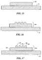
- FIG. 15is a cross-sectional view of a substrate shown in FIG. 1 with a layer of material disposed thereon;
- FIG. 16is a cross-sectional view of the substrate shown in FIG. 15 , after patterning thereof with the template shown in FIG. 14 , in accordance with one embodiment of the present invention
- FIG. 17is a cross-sectional view of the substrate shown in FIG. 15 patterned with the template shown in FIG. 14 , in accordance with a first alternate embodiment of the present invention
- FIG. 18is a cross-sectional view of the template shown in FIG. 14 , having liquid polymerizable layer disposed thereon in accordance with one embodiment of the present invention
- FIG. 19is a cross-sectional view of the substrate shown in FIG. 1 , after patterning thereof with the template shown in FIG. 18 in accordance with a second alternate embodiment of the present invention.
- FIG. 20is a cross-sectional view of the substrate shown in FIG. 15 after patterning thereof with the template shown in FIG. 18 , in accordance with a third alternate embodiment of the present invention.
- FIG. 1depicts a lithographic system 10 in accordance with one embodiment of the present invention that includes a pair of spaced-apart bridge supports 12 having a bridge 14 and a stage support 16 extending therebetween. Bridge 14 and stage support 16 are spaced-apart. Coupled to bridge 14 is an imprint head 18 , which extends from bridge 14 toward stage support 16 . Disposed upon stage support 16 to face imprint head 18 is a motion stage 20 . Motion stage 20 is configured to move with respect to stage support 16 along X and Y axes and may provide movement along the Z axis as well. An exemplary motion stage device is disclosed in U.S. patent application Ser. No. 10/194,414, filed Jul. 11, 2002, entitled “Step and Repeat Imprint Lithography Systems,” assigned to the assignee of the present invention and is incorporated by reference herein. A radiation source 22 is coupled to system 10 to impinge actinic radiation upon motion stage 20 .
- a template 24connected to imprint head 18 is a template 24 having a mold 26 thereon, which may define a smooth or planar surface or have a pattern formed therein.
- mold 26includes a pattern having a plurality of features defined by a plurality of spaced-apart recesses 28 and projections 30 .
- Projections 30have a width W 1
- recesses 28have a width W 2 , both of which are measured in a direction that extends transversely to the Z axis.
- the plurality of featuresdefines an original pattern that forms the basis of a pattern to be transferred into a substrate 32 positioned on motion stage 20 .
- imprint head 18is adapted to move along the Z axis and vary a distance “d” between mold 26 and substrate 32 .
- motion stage 20may move template 24 along the Z-axis. In this manner, the features on mold 26 may be imprinted into a flowable region employed to pattern substrate 32 , discussed more fully below.
- Radiation source 22is located so that mold 26 is positioned between radiation source 22 and substrate 32 , with actinic radiation generated by radiation source 22 propagating through mold 26 .
- mold 26be fabricated from material that is substantially transparent to the actinic radiation.
- Exemplary materials from which mold 26 may be fabricatedinclude fused-silica, quartz, silicon, organic polymers, siloxane polymers, borosilicate glass, fluorocarbon polymers, metal, and combinations of the above dependent upon the actinic radiation employed.
- An exemplary systemis available under the trade name IMPRIO 100TM from Molecular Imprints, Inc. having a place of business at 1807-C Braker Lane, Suite 100, Austin, Tex. 78758. The system description for the IMPRIO 100TM is available at www.molecularimprints.com and is incorporated herein by reference.
- patterned layer 40includes projections 46 that are complementary to the shape of recessions 28 and recesses 48 that are complementary to the shape of protrusions 30 .
- Patterned layer 40results from the placement of polymerizable material between substrate 32 and mold 26 and minimizing distance “d”, leaving projections 46 with a thickness t 1 and recesses 48 with a thickness t 2 .
- Thickness t 2is referred to as a residual thickness. Thicknesses “t 1 ” and “t 2 ” may be any thickness desired, dependent upon the application.
- radiation source 22produces actinic radiation that polymerizes and cross-links the material of pattern layer 40 .
- This processmay be repeated several times to sequentially pattern different regions (not shown) of substrate 32 , referred to as a step and repeat process.
- mold 26may be sized so that the entire area of a surface of substrate 32 is patterned concurrently, i.e., with one imprinting by mold 26 .
- patterned layeris formed by depositing polymerizable material on mold 26 .
- a measure of the polymerizable materialin a flowable/liquid state, is deposited upon mold 26 .
- a portion of the measureingresses into one or more of recessions 28 , filling the volume thereof.
- a quantity of the measure of flowable polymerizable materialis present upon regions of the surface of mold 26 proximate to the one or more recessions 28 of said recess, i.e., outside of the volume of all of the recessions 28 present.
- the portion of the flowable polymerizable materialfills the entire volume of each of recessions 28 present.
- system 10may include one or more fluid dispensing mechanisms 41 that may include one or more spray nozzles, one of which is shown as nozzle 42 .
- Nozzle 42is in fluid communication with a supply 43 , the flowable polymerizable material and a pump 45 .
- Pump 45provides fluid pressure to facilitate projection of material 40 from nozzle 42 , ensuring a sufficient number of droplets (not shown) accumulate on mold 26 to essentially flood the same with a coating 38 of flowable imprinting material to ensure all features are covered and filled.
- Nozzle 42is mounted to motion stage 20 to facilitate having nozzle 42 to be selectively placed in superimposition with any portion of mold 26 . In this manner, coating 38 may be deposited on mold 26 in any pattern desired.
- FIGS. 1 and 4another manner by which to deposit flowable polymerizable material to mold 26 employs a fluid dispensing mechanism 141 with a transfer platen 47 containing the flowable polymerizable material.
- Platen 47may be selectively disposed between mold 26 and substrate 32 , or positioned adjacent to substrate 32 , with mold 26 selectively positioned to be in superimposition therewith. Mold 26 is placed in contact with the flowable polymerizable material contained in platen 47 . The area of platen 47 is established so that the entire area of mold 26 may be placed in contact with material 40 contained in platen 47 .
- this dip-coating techniquemay be employed to create a self-assembled monolayer of flowable polymerizable material on mold 26 not unlike a Langmiur-Blodgette monolayer. However, it is sufficient to merely create a contiguous coating 38 that covers and/or fills the features of the pattern of mold 26 .
- removal of the quantity of flowable polymerizable material outside of the volume of recessionsmay be achieved by subjecting the same to a stream of fluid, such as a gas.
- a vacuum wipe techniquean air knife technique or both may be employed.
- mold 26is exposed to stream of fluid 60 that is contiguous between opposed sides 62 and 64 of mold 26 , in a first direction, such as X, and is substantially smaller than mold 26 , in a second direction, such as Y that extends transversely to the first direction.
- Relative movement between stream of fluid 60 and mold 26 along the Y directionoccurs, e.g., so that movement from side 66 to side 68 occurs. This exposes the entire area of mold 26 to stream of fluid 60 .
- stream of fluid 60is produced by a vacuum wipe 70 that includes a body 72 defining a volume 74 and having an orifice 76 placing said volume in fluid communication with an ambient 78 in which vacuum wipe 70 is disposed.
- Volume 74is placed in fluid communication with a pump system 80 over a feed line 82 .
- Pump system 80creates a pressure differential between volume 74 and ambient 78 so that volume 74 is pressurized to a level that is less than the pressure of ambient 78 , e.g., pump system 80 may create a negative pressure within volume 74 .
- the aforementioned pressure differentialresults in the quantity of liquid polymerizable material not disposed in recessions 28 being drawn away from mold 26 and into a reservoir (not shown) of pump system 80 .
- the pressure differentialis selected so that the portion of liquid polymerizable material disposed within the volume of recessions 28 , remains or a thin layer of polymerizable material remains covering recessions 28 . This is shown with respect to recessions 128 , 228 and 328 .
- orifice 76is provided with a substantially rectangular configuration having a length, l, measured along the X direction between opposed ends 77 and 79 , as well as a width w, and measured along the Y direction.
- Length, lextends in a direction transverse to the relative motion between body 72 and mold 26 , with width, w, being substantially smaller than the length l.
- width, wis at least five times greater than width, w.
- length, lis typically greater than the dimension of mold 26 , which is approximately 25-30 millimeters, and width, w, is selected to optimize removal of the polymerizable material at approximately 0.49 millimeters.
- Body 72is disposed so that orifice 74 faces mold 26 and is spaced-apart therefrom a distance, h, shown more clearly in FIG. 6 .
- Distance his selected based upon several factors, including the viscosity of the polymerizable material disposed on mold 26 , the adhesions characteristics of the polymerizable material to mold 26 , as well as the pressure differential between volume 74 and ambient 78 .
- body 72includes two spaced-apart sets of air bearings, shown as 80 and 90 , flanking orifice 76 .
- orifice 76extends between air bearings 80 and 90 , with end 77 being positioned proximate to air bearing 80 and spaced-apart therefrom.
- End 79is positioned proximate to air bearing 90 and spaced-apart therefrom, e.g., 2 millimeters.
- Air bearings 80 and 90are in fluid communication with a pump system 100 that may be configured to provide the necessary fluid flow.
- each of air bearings 80 and 90includes a plurality of bearing elements, shown as 81 - 88 and 91 - 98 .
- Each of elements 81 - 88is positioned in abutting relationship with each bearing element 81 - 88 adjacent thereto to form a sequence of bearing elements collinear in a direction transverse to the direction along which length, l, is measured. As shown, the sequence along which bearing elements 81 - 88 are arranged is along the Y direction.
- bearing elements 91 - 98are arranged on an opposing side of said body 72 .
- each of bearing elements 81 - 88 and 91 - 98are typically integrally formed with body 72 , and includes a plurality of coplanar areas 99 , 108 and 110 of body 72 . As shown, three polygonal regions are concentrically formed into recessed areas 102 , 104 and 106 . Although each of regions 102 , 104 and 106 has rectangular shapes, any shape may be employed, including non-polygonal shapes, such as a circle. Although not required, the area of region 102 is substantially larger than the area of either region 104 or region 106 , with the region of 106 being greater than the area of region 104 .
- Region 102is separated from region 104 by land 108 that surrounds region 102 and is approximately 1 millimeter in width.
- An additional land 110separates region 104 and 106 .
- the apex surfaces of lands 108 , 110 and surface 99lie in a common plane.
- a throughway 112extends from region 104 parallel to plane P along a direction transverse to terminating in an aperture (not shown) in said body 72 .
- a throughway 112is also present in region 102 , placing the same in fluid communication with pump system 100 .
- a throughway 116is present in region 106 , placing the same in fluid communication with pump system 100 .
- a pressure differentialis created between regions 102 , 104 and 106 , with region 106 having a greater pressure than either regions 102 and 104 .
- pump system 100introduces a positive flow of fluid into throughway 116 pressurizing region 106 to be greater than ambient pressure.
- Pump system 100typically applies a vacuum to throughway 114 , creating a vacuum in region 102 .
- Region 104is typically maintained at ambient pressure levels and operates to stabilize the pressure differential present in regions 102 and 106 .
- body 72is placed in superimposition with template 24 so that orifice 76 extends across an extent of mold 26 with air bearings 80 and 90 being in superimposition with regions of template 24 outside of mold 26 .
- Relative motion between template 24 and body 72 along a single directionis undertaken, referred to as a pass, to remove the liquid polymerizable material, as discussed above. If necessary, however, additional passes may occur in the same direction as the first pass, or in opposite or orthogonal directions, by simply re-orientating template 24 and body 72 by rotating one with respect to the other 90°.
- air bearings 80 and 90are arranged so as to create a positive flow of fluid to impinge upon template 24 pushing body 72 away therefrom to maintain desired spacing, h. It has been found beneficial to independently control fluid propagating between pump system 100 and throughways 114 and 116 . In this manner sudden changes in pressure, such as when one or more of air bearing elements are no longer in superimposition with template 24 , shown as 81 - 83 and 91 - 93 , does not vary the pressure associated with regions 102 , 104 and 106 of the remaining air bearing elements, shown as 84 - 88 and 94 - 98 , that are still in superimposition with template 24 .
- improved stability of the position between mold 26 and orifice 76may be achieved by including more air bearing elements in each of air bearings so as to extend the length of the same in the direction of travel.
- vacuum wipe 170may be formed with a body 172 in which orifice 174 is disposed upon a region 175 , spaced apart from mold 26 a distance, h. The remaining portions of the surface of body 72 facing template 74 , is spaced-apart from template 74 a distance d, which is substantially greater than distance h. In this manner, region 175 forms an island.
- region 275 of body 272is recessed so as to be spaced apart from mold 26 a distance, h.
- Air bearings 80 and 90are spaced-apart from regions of template 24 outside of mold 26 a distance s, which may be the same as or less than distance h. In this manner, were mold 26 formed as a mesa 29 , as shown, mold 26 could be positioned between air bearings 80 and 90 so as to be coplanar therewith.
- vacuum wipemay operate as a gas knife.
- pump system 80creates a positive pressure in volume 74 to produce a high velocity “sheet” of gas (not shown) expelled from orifice 76 .
- This gas “sheet”removes the quantity of fluid not filling the volume of recessions 128 , 228 and 328 , effectively blowing-off the same.
- Thismay be employed in conjunction with the vacuum wipe so that the sheet of gas pushes undesired liquid polymerizable material from the mold 26 and vacuum wipe collects the undesired liquid polymerizable material blown-off by the sheet. Alternating between the gas knife and the vacuum wipe could occur during a single pass or performed on successive passes, as desired.
- the positive pressure in volume 74may be established so as to function as a drier of fluid disposed on mold 26 , e.g., within recessions 128 , 228 and 328 . In this fashion, the velocity of the “sheet” of gas would be established to reduce the probability of removing fluid on mold 26 while drying the same.
- mold 26may be provided with flowable imprinting material deposited so that only the portions of the same, shown as 200 , 202 , 204 and 206 , present in recesses 28 , remain.
- the quantity (not shown) of flowable imprinting material not disposed within recesses 28are absent, i.e., removed.
- portions 200 , 202 , 204 and 206may be disposed on substrate 32 , which may have a pre-existing layer thereon, shown as 300 .
- Pre-existing layermay be one of several layers.
- layer 300may be flowable polymerizable material deposited employing any number of deposition techniques, including spin-coating and drop dispense techniques.
- layer 300formed from a material that is polymerized by the same actinic radiation, e.g., by changes in thermal radiation, and changes in ultra violet radiation, as portions 200 , 202 , 204 and 206 , it is possible to deposit portions 200 , 202 , 204 and 206 , before polymerization of the flowable material from which layer 300 is formed.
- portions 200 , 202 , 204 and 206may be polymerized concurrently with the material from which layer 300 is formed so that the material of portions 200 , 202 , 204 and 206 may cross-link with the material of layer 300 , forming an integral patterned layer 400 .
- layer 300defines residual thickness t 2 , shown in FIG. 2 .
- the residual thickness t 2 , of patterned layer 40may be independent of the fluid dispensed to be imprinted with patterned mold 26 .
- layer 300is polymerized and cross-linked. It should be noted that the matter from which layer 300 may be formed includes constituent components that differ from that which portions 200 , 202 , 204 and 206 are formed. For example, layer 300 may be formed from an organic material and portions 200 , 202 , 204 and 206 may be formed from an inorganic material and vice-versa.
- quantity 599defines the residual thickness t 2 , shown in FIG. 2 .
- the combination of quantity 599 and portions 600 , 602 , 604 and 606facilitate fabrication of an integral patterned layer, 700 , on substrate 32 , with the residual thickness being dependent upon the presence of flowable polymerizable material deposited on mold 26 . It is not necessary to deposit layer 700 directly on substrate 32 .
- substratemay have a pre-existing layer 800 deposited thereon that may have any of the properties discussed above with respect to layer 300 .
- patterned layer 700may be integrally formed with layer 800 (not shown) or may merely be adhered thereto, shown in FIG. 20 as layer 900 .
Landscapes
- Engineering & Computer Science (AREA)
- Nanotechnology (AREA)
- Chemical & Material Sciences (AREA)
- Physics & Mathematics (AREA)
- General Physics & Mathematics (AREA)
- Crystallography & Structural Chemistry (AREA)
- Theoretical Computer Science (AREA)
- Mathematical Physics (AREA)
- Condensed Matter Physics & Semiconductors (AREA)
- Manufacturing & Machinery (AREA)
- Shaping Of Tube Ends By Bending Or Straightening (AREA)
- Exposure Of Semiconductors, Excluding Electron Or Ion Beam Exposure (AREA)
- Moulds For Moulding Plastics Or The Like (AREA)
Abstract
Description
Claims (23)
Priority Applications (4)
| Application Number | Priority Date | Filing Date | Title |
|---|---|---|---|
| US11/101,140US7811505B2 (en) | 2004-12-07 | 2005-04-07 | Method for fast filling of templates for imprint lithography using on template dispense |
| US11/101,139US7281919B2 (en) | 2004-12-07 | 2005-04-07 | System for controlling a volume of material on a mold |
| PCT/US2005/044030WO2006062930A2 (en) | 2004-12-07 | 2005-12-02 | Method and system for fast filling of templates for imprint lithography using on template dispense |
| TW94142945ATWI306802B (en) | 2004-12-07 | 2005-12-06 | Method and system for fast filling of templates for imprint lithography using on template dispense |
Applications Claiming Priority (4)
| Application Number | Priority Date | Filing Date | Title |
|---|---|---|---|
| US636304A | 2004-12-07 | 2004-12-07 | |
| US574204A | 2004-12-07 | 2004-12-07 | |
| US11/101,140US7811505B2 (en) | 2004-12-07 | 2005-04-07 | Method for fast filling of templates for imprint lithography using on template dispense |
| US11/101,139US7281919B2 (en) | 2004-12-07 | 2005-04-07 | System for controlling a volume of material on a mold |
Related Parent Applications (3)
| Application Number | Title | Priority Date | Filing Date |
|---|---|---|---|
| US574204AContinuation-In-Part | 2004-12-07 | 2004-12-07 | |
| US636304AContinuation-In-Part | 2004-12-07 | 2004-12-07 | |
| US11/101,140DivisionUS7811505B2 (en) | 2004-12-07 | 2005-04-07 | Method for fast filling of templates for imprint lithography using on template dispense |
Related Child Applications (1)
| Application Number | Title | Priority Date | Filing Date |
|---|---|---|---|
| US574204ADivision | 2004-12-07 | 2004-12-07 |
Publications (2)
| Publication Number | Publication Date |
|---|---|
| US20060121141A1 US20060121141A1 (en) | 2006-06-08 |
| US7281919B2true US7281919B2 (en) | 2007-10-16 |
Family
ID=36578467
Family Applications (2)
| Application Number | Title | Priority Date | Filing Date |
|---|---|---|---|
| US11/101,139Active2025-12-14US7281919B2 (en) | 2004-12-07 | 2005-04-07 | System for controlling a volume of material on a mold |
| US11/101,140Active2027-11-26US7811505B2 (en) | 2004-12-07 | 2005-04-07 | Method for fast filling of templates for imprint lithography using on template dispense |
Family Applications After (1)
| Application Number | Title | Priority Date | Filing Date |
|---|---|---|---|
| US11/101,140Active2027-11-26US7811505B2 (en) | 2004-12-07 | 2005-04-07 | Method for fast filling of templates for imprint lithography using on template dispense |
Country Status (2)
| Country | Link |
|---|---|
| US (2) | US7281919B2 (en) |
| WO (1) | WO2006062930A2 (en) |
Cited By (24)
| Publication number | Priority date | Publication date | Assignee | Title |
|---|---|---|---|---|
| US20060076717A1 (en)* | 2002-07-11 | 2006-04-13 | Molecular Imprints, Inc. | Step and repeat imprint lithography processes |
| US20060121728A1 (en)* | 2004-12-07 | 2006-06-08 | Molecular Imprints, Inc. | Method for fast filling of templates for imprint lithography using on template dispense |
| US20070231981A1 (en)* | 2006-04-03 | 2007-10-04 | Molecular Imprints, Inc. | Patterning a Plurality of Fields on a Substrate to Compensate for Differing Evaporation Times |
| US20080160129A1 (en)* | 2006-05-11 | 2008-07-03 | Molecular Imprints, Inc. | Template Having a Varying Thickness to Facilitate Expelling a Gas Positioned Between a Substrate and the Template |
| US20080174046A1 (en)* | 2002-07-11 | 2008-07-24 | Molecular Imprints Inc. | Capillary Imprinting Technique |
| US20080303187A1 (en)* | 2006-12-29 | 2008-12-11 | Molecular Imprints, Inc. | Imprint Fluid Control |
| US20090014917A1 (en)* | 2007-07-10 | 2009-01-15 | Molecular Imprints, Inc. | Drop Pattern Generation for Imprint Lithography |
| US20090115110A1 (en)* | 2007-11-02 | 2009-05-07 | Molecular Imprints, Inc. | Drop Pattern Generation for Imprint Lithography |
| US20090200710A1 (en)* | 2008-02-08 | 2009-08-13 | Molecular Imprints, Inc. | Extrusion reduction in imprint lithography |
| US7670529B2 (en) | 2005-12-08 | 2010-03-02 | Molecular Imprints, Inc. | Method and system for double-sided patterning of substrates |
| US7670530B2 (en) | 2006-01-20 | 2010-03-02 | Molecular Imprints, Inc. | Patterning substrates employing multiple chucks |
| US7691313B2 (en) | 2002-11-13 | 2010-04-06 | Molecular Imprints, Inc. | Method for expelling gas positioned between a substrate and a mold |
| US20100098859A1 (en)* | 2008-10-21 | 2010-04-22 | Molecular Imprints, Inc. | Drop Pattern Generation with Edge Weighting |
| US20100096764A1 (en)* | 2008-10-20 | 2010-04-22 | Molecular Imprints, Inc. | Gas Environment for Imprint Lithography |
| US20100112220A1 (en)* | 2008-11-03 | 2010-05-06 | Molecular Imprints, Inc. | Dispense system set-up and characterization |
| US20100237042A1 (en)* | 2009-03-23 | 2010-09-23 | Intevac, Inc. | Process for optimization of island to trench ratio in patterned media |
| US20110059406A1 (en)* | 2009-09-10 | 2011-03-10 | Yoshihisa Kawamura | Pattern forming method |
| US7906058B2 (en) | 2005-12-01 | 2011-03-15 | Molecular Imprints, Inc. | Bifurcated contact printing technique |
| US20110159209A1 (en)* | 2009-12-24 | 2011-06-30 | Yoshihisa Kawamura | Pattern forming method |
| US7981481B2 (en) | 2004-09-23 | 2011-07-19 | Molecular Imprints, Inc. | Method for controlling distribution of fluid components on a body |
| US8211214B2 (en) | 2003-10-02 | 2012-07-03 | Molecular Imprints, Inc. | Single phase fluid imprint lithography method |
| US8215946B2 (en) | 2006-05-18 | 2012-07-10 | Molecular Imprints, Inc. | Imprint lithography system and method |
| US8586126B2 (en) | 2008-10-21 | 2013-11-19 | Molecular Imprints, Inc. | Robust optimization to generate drop patterns in imprint lithography which are tolerant of variations in drop volume and drop placement |
| US9223202B2 (en) | 2000-07-17 | 2015-12-29 | Board Of Regents, The University Of Texas System | Method of automatic fluid dispensing for imprint lithography processes |
Families Citing this family (8)
| Publication number | Priority date | Publication date | Assignee | Title |
|---|---|---|---|---|
| US7162035B1 (en) | 2000-05-24 | 2007-01-09 | Tracer Detection Technology Corp. | Authentication method and system |
| KR101193918B1 (en)* | 2004-06-03 | 2012-10-29 | 몰레큘러 임프린츠 인코퍼레이티드 | Fluid dispensing and drop-on-demand dispensing for nano-scale menufacturing |
| US20070228593A1 (en)* | 2006-04-03 | 2007-10-04 | Molecular Imprints, Inc. | Residual Layer Thickness Measurement and Correction |
| US7995196B1 (en) | 2008-04-23 | 2011-08-09 | Tracer Detection Technology Corp. | Authentication method and system |
| AU2009286690A1 (en) | 2008-08-27 | 2010-03-04 | Amo Gmbh | Improved nanoimprint method |
| US9168679B2 (en)* | 2010-07-16 | 2015-10-27 | Northwestern University | Programmable soft lithography: solvent-assisted nanoscale embossing |
| DE102013113241B4 (en)* | 2013-11-29 | 2019-02-21 | Ev Group E. Thallner Gmbh | Method for embossing structures |
| JP6384537B2 (en)* | 2016-10-18 | 2018-09-05 | 大日本印刷株式会社 | Nanoimprint template |
Citations (50)
| Publication number | Priority date | Publication date | Assignee | Title |
|---|---|---|---|---|
| US2212863A (en)* | 1940-03-02 | 1940-08-27 | Eric C Hughes | Evacuator |
| US3151196A (en)* | 1960-08-08 | 1964-09-29 | Eagle Rubber Co Inc | Method of making balls |
| US4451507A (en) | 1982-10-29 | 1984-05-29 | Rca Corporation | Automatic liquid dispensing apparatus for spinning surface of uniform thickness |
| US4614300A (en) | 1982-04-19 | 1986-09-30 | E. I. Du Pont De Nemours And Company | Computerized spray machine |
| JPH0224848A (en) | 1988-07-14 | 1990-01-26 | Canon Inc | Production of substrate for optical recording medium |
| JPH0292603A (en) | 1988-09-30 | 1990-04-03 | Hoya Corp | Manufacture of data recording board with guide groove |
| US4999280A (en) | 1989-03-17 | 1991-03-12 | International Business Machines Corporation | Spray silylation of photoresist images |
| US5078947A (en)* | 1988-09-30 | 1992-01-07 | Victor Company Of Japan, Ltd. | Method and apparatus for the fabrication of optical record media such as a digital audio disc |
| US5507411A (en) | 1990-02-09 | 1996-04-16 | Berg Company, A Division Of Dec International, Inc. | Electronic dispensing heads |
| US5694961A (en) | 1993-02-25 | 1997-12-09 | J.M. Voith Gmbh | Device and method for changing the flow resistance of a fluid flow control device |
| US5723176A (en) | 1994-03-02 | 1998-03-03 | Telecommunications Research Laboratories | Method and apparatus for making optical components by direct dispensing of curable liquid |
| US5731981A (en) | 1992-06-08 | 1998-03-24 | Azbar, Inc. | Beverage dispensing system for bar |
| US5747102A (en) | 1995-11-16 | 1998-05-05 | Nordson Corporation | Method and apparatus for dispensing small amounts of liquid material |
| WO1998024070A1 (en) | 1996-11-28 | 1998-06-04 | Sofabodi - Societe De Fabrication De Bornes De Distribution | Method and device for authorising and controlling with a memory card the dispensing and metering of the consumption of a fluid or energy |
| US5772905A (en) | 1995-11-15 | 1998-06-30 | Regents Of The University Of Minnesota | Nanoimprint lithography |
| US5837892A (en) | 1996-10-25 | 1998-11-17 | Camelot Systems, Inc. | Method and apparatus for measuring the size of drops of a viscous material dispensed from a dispensing system |
| US5912049A (en) | 1997-08-12 | 1999-06-15 | Micron Technology, Inc. | Process liquid dispense method and apparatus |
| US5988859A (en) | 1997-07-30 | 1999-11-23 | Kirk; Lester C. | Apparatus for dispensing valuable bulk commodities and method therefor |
| US6027595A (en) | 1998-07-02 | 2000-02-22 | Samsung Electronics Co., Ltd. | Method of making optical replicas by stamping in photoresist and replicas formed thereby |
| US6089853A (en) | 1997-12-24 | 2000-07-18 | International Business Machines Corporation | Patterning device for patterning a substrate with patterning cavities fed by service cavities |
| US6112588A (en) | 1996-10-25 | 2000-09-05 | Speedline Technologies, Inc. | Method and apparatus for measuring the size of drops of a viscous material dispensed from a dispensing system |
| US6234379B1 (en) | 2000-02-28 | 2001-05-22 | Nordson Corporation | No-flow flux and underfill dispensing methods |
| US6279474B1 (en) | 1993-08-13 | 2001-08-28 | Heidelberger Druckmaschinen Ag | Method and device for transferring ink in a printing unit of an offset printing press |
| US6309580B1 (en) | 1995-11-15 | 2001-10-30 | Regents Of The University Of Minnesota | Release surfaces, particularly for use in nanoimprint lithography |
| US6334960B1 (en) | 1999-03-11 | 2002-01-01 | Board Of Regents, The University Of Texas System | Step and flash imprint lithography |
| US20020005880A1 (en) | 1996-04-23 | 2002-01-17 | Xaar Technology Limited | Droplet deposition apparatus |
| US6361831B1 (en) | 1999-04-06 | 2002-03-26 | Matsushita Electric Industrial Co., Ltd. | Paste application method for die bonding |
| US6377868B1 (en) | 1999-10-28 | 2002-04-23 | Ecolab Inc. | Data processing system for managing chemical product usage |
| US20020094496A1 (en)* | 2000-07-17 | 2002-07-18 | Choi Byung J. | Method and system of automatic fluid dispensing for imprint lithography processes |
| US20020135099A1 (en) | 2001-01-19 | 2002-09-26 | Robinson Timothy R. | Mold with metal oxide surface compatible with ionic release agents |
| US6510356B2 (en) | 2001-04-02 | 2003-01-21 | Hewlett-Packard Company | Method and apparatus for programming a paste dispensing machine |
| US6588632B1 (en) | 2001-11-20 | 2003-07-08 | Gorham Nicol | Programmable beverage dispensing apparatus |
| US6600969B2 (en) | 1999-05-20 | 2003-07-29 | Lancer Partnership, Ltd. | Beverage dispenser including an improved electronic control system |
| US6646662B1 (en) | 1998-05-26 | 2003-11-11 | Seiko Epson Corporation | Patterning method, patterning apparatus, patterning template, and method for manufacturing the patterning template |
| US20040022888A1 (en)* | 2002-08-01 | 2004-02-05 | Sreenivasan Sidlgata V. | Alignment systems for imprint lithography |
| US20040029041A1 (en) | 2002-02-27 | 2004-02-12 | Brewer Science, Inc. | Novel planarization method for multi-layer lithography processing |
| US20040058067A1 (en) | 2002-09-19 | 2004-03-25 | Law Kam S. | Method and apparatus for metallization of large area substrates |
| US20040065976A1 (en) | 2002-10-04 | 2004-04-08 | Sreenivasan Sidlgata V. | Method and a mold to arrange features on a substrate to replicate features having minimal dimensional variability |
| US6805541B1 (en)* | 1999-02-15 | 2004-10-19 | Kabushiki Kaisha Toshiba | Resin encapsulating apparatus used in a manufacture of a semiconductor device |
| US6820677B2 (en) | 2002-08-20 | 2004-11-23 | Ford Motor Company | Method of making a spray formed article |
| US20040231781A1 (en) | 2003-05-23 | 2004-11-25 | Agency For Science, Technology And Research | Methods of creating patterns on substrates and articles of manufacture resulting therefrom |
| US20040241324A1 (en)* | 2002-07-09 | 2004-12-02 | Molecular Imprints, Inc. | System for dispensing liquids |
| US20040256764A1 (en) | 2003-06-17 | 2004-12-23 | University Of Texas System Board Of Regents | Method to reduce adhesion between a conformable region and a pattern of a mold |
| US6855293B1 (en) | 1999-03-23 | 2005-02-15 | Hahn-Schickard-Gesellschaft Fuer Angewandte Forschung E.V. | Fluids manipulation device with format conversion |
| US20050056963A1 (en)* | 2003-07-10 | 2005-03-17 | Mccutcheon Jeremy W. | Automated process and apparatus for planarization of topographical surfaces |
| US20050106321A1 (en) | 2003-11-14 | 2005-05-19 | Molecular Imprints, Inc. | Dispense geometery to achieve high-speed filling and throughput |
| US20050160011A1 (en) | 2004-01-20 | 2005-07-21 | Molecular Imprints, Inc. | Method for concurrently employing differing materials to form a layer on a substrate |
| US20050189676A1 (en) | 2004-02-27 | 2005-09-01 | Molecular Imprints, Inc. | Full-wafer or large area imprinting with multiple separated sub-fields for high throughput lithography |
| US20050270312A1 (en) | 2004-06-03 | 2005-12-08 | Molecular Imprints, Inc. | Fluid dispensing and drop-on-demand dispensing for nano-scale manufacturing |
| US20060121728A1 (en) | 2004-12-07 | 2006-06-08 | Molecular Imprints, Inc. | Method for fast filling of templates for imprint lithography using on template dispense |
Family Cites Families (81)
| Publication number | Priority date | Publication date | Assignee | Title |
|---|---|---|---|---|
| US3044396A (en)* | 1959-01-02 | 1962-07-17 | Carl Allers Ets | Inking mechanism for intaglio printing machines |
| US3176653A (en)* | 1963-02-20 | 1965-04-06 | Rca Corp | Fluid applicator apparatus |
| US4512848A (en) | 1984-02-06 | 1985-04-23 | Exxon Research And Engineering Co. | Procedure for fabrication of microstructures over large areas using physical replication |
| KR900004269B1 (en) | 1986-06-11 | 1990-06-18 | 가부시기가이샤 도시바 | Method and device for positioing 1st body and 2nd body |
| FR2604553A1 (en) | 1986-09-29 | 1988-04-01 | Rhone Poulenc Chimie | RIGID POLYMER SUBSTRATE FOR OPTICAL DISC AND OPTICAL DISCS OBTAINED FROM THE SUBSTRATE |
| US4731155A (en) | 1987-04-15 | 1988-03-15 | General Electric Company | Process for forming a lithographic mask |
| US5028366A (en) | 1988-01-12 | 1991-07-02 | Air Products And Chemicals, Inc. | Water based mold release compositions for making molded polyurethane foam |
| JP2546350B2 (en) | 1988-09-09 | 1996-10-23 | キヤノン株式会社 | Alignment device |
| US5110514A (en) | 1989-05-01 | 1992-05-05 | Soane Technologies, Inc. | Controlled casting of a shrinkable material |
| DE4031637C2 (en) | 1989-10-06 | 1997-04-10 | Toshiba Kawasaki Kk | Arrangement for measuring a displacement between two objects |
| DE4029912A1 (en) | 1990-09-21 | 1992-03-26 | Philips Patentverwaltung | METHOD FOR FORMING AT LEAST ONE TRENCH IN A SUBSTRATE LAYER |
| US5362940A (en) | 1990-11-09 | 1994-11-08 | Litel Instruments | Use of Fresnel zone plates for material processing |
| JPH0580530A (en) | 1991-09-24 | 1993-04-02 | Hitachi Ltd | Production of thin film pattern |
| US5545367A (en) | 1992-04-15 | 1996-08-13 | Soane Technologies, Inc. | Rapid prototype three dimensional stereolithography |
| US5371822A (en) | 1992-06-09 | 1994-12-06 | Digital Equipment Corporation | Method of packaging and assembling opto-electronic integrated circuits |
| US5601641A (en) | 1992-07-21 | 1997-02-11 | Tse Industries, Inc. | Mold release composition with polybutadiene and method of coating a mold core |
| DE69405451T2 (en) | 1993-03-16 | 1998-03-12 | Koninkl Philips Electronics Nv | Method and device for producing a structured relief image from cross-linked photoresist on a flat substrate surface |
| JP2837063B2 (en) | 1993-06-04 | 1998-12-14 | シャープ株式会社 | Method of forming resist pattern |
| US5512131A (en) | 1993-10-04 | 1996-04-30 | President And Fellows Of Harvard College | Formation of microstamped patterns on surfaces and derivative articles |
| US6776094B1 (en) | 1993-10-04 | 2004-08-17 | President & Fellows Of Harvard College | Kit For Microcontact Printing |
| US5776748A (en) | 1993-10-04 | 1998-07-07 | President And Fellows Of Harvard College | Method of formation of microstamped patterns on plates for adhesion of cells and other biological materials, devices and uses therefor |
| JPH08187927A (en)* | 1994-11-09 | 1996-07-23 | Nippon Oil Co Ltd | Transfer method by printing |
| US5849209A (en) | 1995-03-31 | 1998-12-15 | Johnson & Johnson Vision Products, Inc. | Mold material made with additives |
| US6342389B1 (en) | 1995-04-10 | 2002-01-29 | Roger S. Cubicciotti | Modified phycobilisomes and uses therefore |
| US5562951A (en)* | 1995-05-01 | 1996-10-08 | Revlon Consumer Products Corporation | Method for printing articles with multiple radiation curable compositions |
| GB9509487D0 (en) | 1995-05-10 | 1995-07-05 | Ici Plc | Micro relief element & preparation thereof |
| US5820769A (en) | 1995-05-24 | 1998-10-13 | Regents Of The University Of Minnesota | Method for making magnetic storage having discrete elements with quantized magnetic moments |
| US5849222A (en) | 1995-09-29 | 1998-12-15 | Johnson & Johnson Vision Products, Inc. | Method for reducing lens hole defects in production of contact lens blanks |
| US20030080471A1 (en) | 2001-10-29 | 2003-05-01 | Chou Stephen Y. | Lithographic method for molding pattern with nanoscale features |
| US6482742B1 (en) | 2000-07-18 | 2002-11-19 | Stephen Y. Chou | Fluid pressure imprint lithography |
| US20040137734A1 (en) | 1995-11-15 | 2004-07-15 | Princeton University | Compositions and processes for nanoimprinting |
| US7758794B2 (en) | 2001-10-29 | 2010-07-20 | Princeton University | Method of making an article comprising nanoscale patterns with reduced edge roughness |
| US20040036201A1 (en) | 2000-07-18 | 2004-02-26 | Princeton University | Methods and apparatus of field-induced pressure imprint lithography |
| US6518189B1 (en) | 1995-11-15 | 2003-02-11 | Regents Of The University Of Minnesota | Method and apparatus for high density nanostructures |
| US5669303A (en) | 1996-03-04 | 1997-09-23 | Motorola | Apparatus and method for stamping a surface |
| US6355198B1 (en) | 1996-03-15 | 2002-03-12 | President And Fellows Of Harvard College | Method of forming articles including waveguides via capillary micromolding and microtransfer molding |
| US5942443A (en) | 1996-06-28 | 1999-08-24 | Caliper Technologies Corporation | High throughput screening assay systems in microscale fluidic devices |
| US5888650A (en) | 1996-06-03 | 1999-03-30 | Minnesota Mining And Manufacturing Company | Temperature-responsive adhesive article |
| US6074827A (en) | 1996-07-30 | 2000-06-13 | Aclara Biosciences, Inc. | Microfluidic method for nucleic acid purification and processing |
| US5858580A (en) | 1997-09-17 | 1999-01-12 | Numerical Technologies, Inc. | Phase shifting circuit manufacture method and apparatus |
| US6228539B1 (en) | 1996-09-18 | 2001-05-08 | Numerical Technologies, Inc. | Phase shifting circuit manufacture method and apparatus |
| TW353762B (en)* | 1996-10-21 | 1999-03-01 | Dainippon Printing Co Ltd | Transfer sheet, and pattern-forming method |
| US5938080A (en) | 1997-02-21 | 1999-08-17 | The Geon Company | System and apparatus for dispensing high-viscosity pigments |
| US5948470A (en) | 1997-04-28 | 1999-09-07 | Harrison; Christopher | Method of nanoscale patterning and products made thereby |
| US5812629A (en) | 1997-04-30 | 1998-09-22 | Clauser; John F. | Ultrahigh resolution interferometric x-ray imaging |
| US5974150A (en) | 1997-09-30 | 1999-10-26 | Tracer Detection Technology Corp. | System and method for authentication of goods |
| US6713238B1 (en) | 1998-10-09 | 2004-03-30 | Stephen Y. Chou | Microscale patterning and articles formed thereby |
| US6218316B1 (en) | 1998-10-22 | 2001-04-17 | Micron Technology, Inc. | Planarization of non-planar surfaces in device fabrication |
| US6274294B1 (en) | 1999-02-03 | 2001-08-14 | Electroformed Stents, Inc. | Cylindrical photolithography exposure process and apparatus |
| US6517995B1 (en) | 1999-09-14 | 2003-02-11 | Massachusetts Institute Of Technology | Fabrication of finely featured devices by liquid embossing |
| US6873087B1 (en) | 1999-10-29 | 2005-03-29 | Board Of Regents, The University Of Texas System | High precision orientation alignment and gap control stages for imprint lithography processes |
| ATE294648T1 (en) | 1999-12-23 | 2005-05-15 | Univ Massachusetts | METHOD FOR PRODUCING SUBMICRON PATTERNS ON FILM |
| US6498640B1 (en) | 1999-12-30 | 2002-12-24 | Koninklijke Philips Electronics N.V. | Method to measure alignment using latent image grating structures |
| US7859519B2 (en) | 2000-05-01 | 2010-12-28 | Tulbert David J | Human-machine interface |
| AU2001273491A1 (en) | 2000-07-16 | 2002-02-05 | Board Of Regents, The University Of Texas System | High-resolution overlay alignment methods and systems for imprint lithography |
| US7635262B2 (en) | 2000-07-18 | 2009-12-22 | Princeton University | Lithographic apparatus for fluid pressure imprint lithography |
| US20050037143A1 (en) | 2000-07-18 | 2005-02-17 | Chou Stephen Y. | Imprint lithography with improved monitoring and control and apparatus therefor |
| US7211214B2 (en) | 2000-07-18 | 2007-05-01 | Princeton University | Laser assisted direct imprint lithography |
| US6326627B1 (en) | 2000-08-02 | 2001-12-04 | Archimedes Technology Group, Inc. | Mass filtering sputtered ion source |
| EP1352295B1 (en) | 2000-10-12 | 2015-12-23 | Board of Regents, The University of Texas System | Template for room temperature, low pressure micro- and nano-imprint lithography |
| US6387787B1 (en) | 2001-03-02 | 2002-05-14 | Motorola, Inc. | Lithographic template and method of formation and use |
| US6955767B2 (en) | 2001-03-22 | 2005-10-18 | Hewlett-Packard Development Company, Lp. | Scanning probe based lithographic alignment |
| US6517977B2 (en) | 2001-03-28 | 2003-02-11 | Motorola, Inc. | Lithographic template and method of formation and use |
| US6964793B2 (en) | 2002-05-16 | 2005-11-15 | Board Of Regents, The University Of Texas System | Method for fabricating nanoscale patterns in light curable compositions using an electric field |
| US6847433B2 (en) | 2001-06-01 | 2005-01-25 | Agere Systems, Inc. | Holder, system, and process for improving overlay in lithography |
| US7049049B2 (en) | 2001-06-27 | 2006-05-23 | University Of South Florida | Maskless photolithography for using photoreactive agents |
| JP2003084123A (en) | 2001-06-29 | 2003-03-19 | Seiko Epson Corp | Color filter substrate, method for manufacturing color filter substrate, liquid crystal display device, electro-optical device, method for manufacturing electro-optical device, and electronic apparatus |
| SG169225A1 (en) | 2001-07-25 | 2011-03-30 | Univ Princeton | Nanochannel arrays and their preparation and use for high throughput macromolecular analysis |
| US6678038B2 (en) | 2001-08-03 | 2004-01-13 | Nikon Corporation | Apparatus and methods for detecting tool-induced shift in microlithography apparatus |
| CN100347608C (en) | 2001-09-25 | 2007-11-07 | 米卢塔技术株式会社 | Method for forming a micro-pattern on a substrate by using capillary force |
| US6621960B2 (en) | 2002-01-24 | 2003-09-16 | Oplink Communications, Inc. | Method of fabricating multiple superimposed fiber Bragg gratings |
| US7117583B2 (en) | 2002-03-18 | 2006-10-10 | International Business Machines Corporation | Method and apparatus using a pre-patterned seed layer for providing an aligned coil for an inductive head structure |
| US6849558B2 (en) | 2002-05-22 | 2005-02-01 | The Board Of Trustees Of The Leland Stanford Junior University | Replication and transfer of microstructures and nanostructures |
| US6932934B2 (en) | 2002-07-11 | 2005-08-23 | Molecular Imprints, Inc. | Formation of discontinuous films during an imprint lithography process |
| US6900881B2 (en) | 2002-07-11 | 2005-05-31 | Molecular Imprints, Inc. | Step and repeat imprint lithography systems |
| US7077992B2 (en) | 2002-07-11 | 2006-07-18 | Molecular Imprints, Inc. | Step and repeat imprint lithography processes |
| US6908861B2 (en) | 2002-07-11 | 2005-06-21 | Molecular Imprints, Inc. | Method for imprint lithography using an electric field |
| US6916584B2 (en) | 2002-08-01 | 2005-07-12 | Molecular Imprints, Inc. | Alignment methods for imprint lithography |
| US7750059B2 (en) | 2002-12-04 | 2010-07-06 | Hewlett-Packard Development Company, L.P. | Polymer solution for nanoimprint lithography to reduce imprint temperature and pressure |
| US6943117B2 (en) | 2003-03-27 | 2005-09-13 | Korea Institute Of Machinery & Materials | UV nanoimprint lithography process using elementwise embossed stamp and selectively additive pressurization |
| TWI228638B (en) | 2003-06-10 | 2005-03-01 | Ind Tech Res Inst | Method for and apparatus for bonding patterned imprint to a substrate by adhering means |
- 2005
- 2005-04-07USUS11/101,139patent/US7281919B2/enactiveActive
- 2005-04-07USUS11/101,140patent/US7811505B2/enactiveActive
- 2005-12-02WOPCT/US2005/044030patent/WO2006062930A2/enactiveApplication Filing
Patent Citations (51)
| Publication number | Priority date | Publication date | Assignee | Title |
|---|---|---|---|---|
| US2212863A (en)* | 1940-03-02 | 1940-08-27 | Eric C Hughes | Evacuator |
| US3151196A (en)* | 1960-08-08 | 1964-09-29 | Eagle Rubber Co Inc | Method of making balls |
| US4614300A (en) | 1982-04-19 | 1986-09-30 | E. I. Du Pont De Nemours And Company | Computerized spray machine |
| US4451507A (en) | 1982-10-29 | 1984-05-29 | Rca Corporation | Automatic liquid dispensing apparatus for spinning surface of uniform thickness |
| JPH0224848A (en) | 1988-07-14 | 1990-01-26 | Canon Inc | Production of substrate for optical recording medium |
| JPH0292603A (en) | 1988-09-30 | 1990-04-03 | Hoya Corp | Manufacture of data recording board with guide groove |
| US5078947A (en)* | 1988-09-30 | 1992-01-07 | Victor Company Of Japan, Ltd. | Method and apparatus for the fabrication of optical record media such as a digital audio disc |
| US4999280A (en) | 1989-03-17 | 1991-03-12 | International Business Machines Corporation | Spray silylation of photoresist images |
| US5507411A (en) | 1990-02-09 | 1996-04-16 | Berg Company, A Division Of Dec International, Inc. | Electronic dispensing heads |
| US5731981A (en) | 1992-06-08 | 1998-03-24 | Azbar, Inc. | Beverage dispensing system for bar |
| US5694961A (en) | 1993-02-25 | 1997-12-09 | J.M. Voith Gmbh | Device and method for changing the flow resistance of a fluid flow control device |
| US6279474B1 (en) | 1993-08-13 | 2001-08-28 | Heidelberger Druckmaschinen Ag | Method and device for transferring ink in a printing unit of an offset printing press |
| US5723176A (en) | 1994-03-02 | 1998-03-03 | Telecommunications Research Laboratories | Method and apparatus for making optical components by direct dispensing of curable liquid |
| US5772905A (en) | 1995-11-15 | 1998-06-30 | Regents Of The University Of Minnesota | Nanoimprint lithography |
| US6309580B1 (en) | 1995-11-15 | 2001-10-30 | Regents Of The University Of Minnesota | Release surfaces, particularly for use in nanoimprint lithography |
| US5747102A (en) | 1995-11-16 | 1998-05-05 | Nordson Corporation | Method and apparatus for dispensing small amounts of liquid material |
| US20020005880A1 (en) | 1996-04-23 | 2002-01-17 | Xaar Technology Limited | Droplet deposition apparatus |
| US5837892A (en) | 1996-10-25 | 1998-11-17 | Camelot Systems, Inc. | Method and apparatus for measuring the size of drops of a viscous material dispensed from a dispensing system |
| US6112588A (en) | 1996-10-25 | 2000-09-05 | Speedline Technologies, Inc. | Method and apparatus for measuring the size of drops of a viscous material dispensed from a dispensing system |
| WO1998024070A1 (en) | 1996-11-28 | 1998-06-04 | Sofabodi - Societe De Fabrication De Bornes De Distribution | Method and device for authorising and controlling with a memory card the dispensing and metering of the consumption of a fluid or energy |
| US5988859A (en) | 1997-07-30 | 1999-11-23 | Kirk; Lester C. | Apparatus for dispensing valuable bulk commodities and method therefor |
| US5912049A (en) | 1997-08-12 | 1999-06-15 | Micron Technology, Inc. | Process liquid dispense method and apparatus |
| US6089853A (en) | 1997-12-24 | 2000-07-18 | International Business Machines Corporation | Patterning device for patterning a substrate with patterning cavities fed by service cavities |
| US6646662B1 (en) | 1998-05-26 | 2003-11-11 | Seiko Epson Corporation | Patterning method, patterning apparatus, patterning template, and method for manufacturing the patterning template |
| US6027595A (en) | 1998-07-02 | 2000-02-22 | Samsung Electronics Co., Ltd. | Method of making optical replicas by stamping in photoresist and replicas formed thereby |
| US6805541B1 (en)* | 1999-02-15 | 2004-10-19 | Kabushiki Kaisha Toshiba | Resin encapsulating apparatus used in a manufacture of a semiconductor device |
| US6334960B1 (en) | 1999-03-11 | 2002-01-01 | Board Of Regents, The University Of Texas System | Step and flash imprint lithography |
| US6855293B1 (en) | 1999-03-23 | 2005-02-15 | Hahn-Schickard-Gesellschaft Fuer Angewandte Forschung E.V. | Fluids manipulation device with format conversion |
| US6361831B1 (en) | 1999-04-06 | 2002-03-26 | Matsushita Electric Industrial Co., Ltd. | Paste application method for die bonding |
| US6600969B2 (en) | 1999-05-20 | 2003-07-29 | Lancer Partnership, Ltd. | Beverage dispenser including an improved electronic control system |
| US6377868B1 (en) | 1999-10-28 | 2002-04-23 | Ecolab Inc. | Data processing system for managing chemical product usage |
| US6234379B1 (en) | 2000-02-28 | 2001-05-22 | Nordson Corporation | No-flow flux and underfill dispensing methods |
| US20020094496A1 (en)* | 2000-07-17 | 2002-07-18 | Choi Byung J. | Method and system of automatic fluid dispensing for imprint lithography processes |
| US20020135099A1 (en) | 2001-01-19 | 2002-09-26 | Robinson Timothy R. | Mold with metal oxide surface compatible with ionic release agents |
| US6510356B2 (en) | 2001-04-02 | 2003-01-21 | Hewlett-Packard Company | Method and apparatus for programming a paste dispensing machine |
| US6588632B1 (en) | 2001-11-20 | 2003-07-08 | Gorham Nicol | Programmable beverage dispensing apparatus |
| US20040029041A1 (en) | 2002-02-27 | 2004-02-12 | Brewer Science, Inc. | Novel planarization method for multi-layer lithography processing |
| US20040241324A1 (en)* | 2002-07-09 | 2004-12-02 | Molecular Imprints, Inc. | System for dispensing liquids |
| US6926929B2 (en)* | 2002-07-09 | 2005-08-09 | Molecular Imprints, Inc. | System and method for dispensing liquids |
| US20040022888A1 (en)* | 2002-08-01 | 2004-02-05 | Sreenivasan Sidlgata V. | Alignment systems for imprint lithography |
| US6820677B2 (en) | 2002-08-20 | 2004-11-23 | Ford Motor Company | Method of making a spray formed article |
| US20040058067A1 (en) | 2002-09-19 | 2004-03-25 | Law Kam S. | Method and apparatus for metallization of large area substrates |
| US20040065976A1 (en) | 2002-10-04 | 2004-04-08 | Sreenivasan Sidlgata V. | Method and a mold to arrange features on a substrate to replicate features having minimal dimensional variability |
| US20040231781A1 (en) | 2003-05-23 | 2004-11-25 | Agency For Science, Technology And Research | Methods of creating patterns on substrates and articles of manufacture resulting therefrom |
| US20040256764A1 (en) | 2003-06-17 | 2004-12-23 | University Of Texas System Board Of Regents | Method to reduce adhesion between a conformable region and a pattern of a mold |
| US20050056963A1 (en)* | 2003-07-10 | 2005-03-17 | Mccutcheon Jeremy W. | Automated process and apparatus for planarization of topographical surfaces |
| US20050106321A1 (en) | 2003-11-14 | 2005-05-19 | Molecular Imprints, Inc. | Dispense geometery to achieve high-speed filling and throughput |
| US20050160011A1 (en) | 2004-01-20 | 2005-07-21 | Molecular Imprints, Inc. | Method for concurrently employing differing materials to form a layer on a substrate |
| US20050189676A1 (en) | 2004-02-27 | 2005-09-01 | Molecular Imprints, Inc. | Full-wafer or large area imprinting with multiple separated sub-fields for high throughput lithography |
| US20050270312A1 (en) | 2004-06-03 | 2005-12-08 | Molecular Imprints, Inc. | Fluid dispensing and drop-on-demand dispensing for nano-scale manufacturing |
| US20060121728A1 (en) | 2004-12-07 | 2006-06-08 | Molecular Imprints, Inc. | Method for fast filling of templates for imprint lithography using on template dispense |
Non-Patent Citations (11)
| Title |
|---|
| Abstract of Japanese Patent 02-24848, Jan. 26, 1990. |
| Abstract of Japanese Patent 02-92603, Aug. 12, 2004. |
| Brubaker et al., Investigating The Use of Spray-Coating Technology in MEMS Applications, Micro Magazine, pp. 45-55 Mar. 1, 2004. |
| Chou et al., Nanoimprint Lithography, Journal of Vacuum Science Technolgoy B 14(16), pp. 4129-4133 Nov. 1, 1996. |
| Nerac.com Retro Search, Fluid Dispensing, May 4, 2005. |
| U.S. Appl. No. 10/858,566, naming Inventors Truskett et al., entitled A Method for Dispensing a Fluid on a Substrate, filed Jun. 1, 2004. |
| U.S. Appl. No. 11/005,742, naming Inventors McMackin et al., entitled Method for Fast Filling of Templates for Imprint Lithography using on Template Dispense, filed Dec. 7, 2004. |
| U.S. Appl. No. 11/006,363, naming Inventors McMackin et al., entitled System for Controlling a Volume of Material Remaining on a Mold Employed in Fast Filling Imprint Lithography Processes, filed Dec. 7, 2004. |
| U.S. Appl. No. 11/012,375, naming Inventors Xu et al., entitled Method to Reduce Adhesion between a Conformable Region and a Mold, filed Dec. 15, 2004. |
| U.S. Appl. No. 11/143,092, naming Inventors Lad et al., entitled Fluid Dispensing and Drop-on-Demand Dispensing for Nano-Scale Manufacturing, filed Jun. 2, 2005. |
| U.S. Appl. No. 11/459,797, naming Inventors Choi et al., entitled Method for Providing Desirable Wetting and Release Characteristics between a Mold and a Polymerizable Composition, filed Jul. 25, 2006. |
Cited By (34)
| Publication number | Priority date | Publication date | Assignee | Title |
|---|---|---|---|---|
| US9223202B2 (en) | 2000-07-17 | 2015-12-29 | Board Of Regents, The University Of Texas System | Method of automatic fluid dispensing for imprint lithography processes |
| US7727453B2 (en) | 2002-07-11 | 2010-06-01 | Molecular Imprints, Inc. | Step and repeat imprint lithography processes |
| US20080174046A1 (en)* | 2002-07-11 | 2008-07-24 | Molecular Imprints Inc. | Capillary Imprinting Technique |
| US20060076717A1 (en)* | 2002-07-11 | 2006-04-13 | Molecular Imprints, Inc. | Step and repeat imprint lithography processes |
| US7708926B2 (en) | 2002-07-11 | 2010-05-04 | Molecular Imprints, Inc. | Capillary imprinting technique |
| US7691313B2 (en) | 2002-11-13 | 2010-04-06 | Molecular Imprints, Inc. | Method for expelling gas positioned between a substrate and a mold |
| US8211214B2 (en) | 2003-10-02 | 2012-07-03 | Molecular Imprints, Inc. | Single phase fluid imprint lithography method |
| US7981481B2 (en) | 2004-09-23 | 2011-07-19 | Molecular Imprints, Inc. | Method for controlling distribution of fluid components on a body |
| US7811505B2 (en) | 2004-12-07 | 2010-10-12 | Molecular Imprints, Inc. | Method for fast filling of templates for imprint lithography using on template dispense |
| US20060121728A1 (en)* | 2004-12-07 | 2006-06-08 | Molecular Imprints, Inc. | Method for fast filling of templates for imprint lithography using on template dispense |
| US7906058B2 (en) | 2005-12-01 | 2011-03-15 | Molecular Imprints, Inc. | Bifurcated contact printing technique |
| US7670529B2 (en) | 2005-12-08 | 2010-03-02 | Molecular Imprints, Inc. | Method and system for double-sided patterning of substrates |
| US7670530B2 (en) | 2006-01-20 | 2010-03-02 | Molecular Imprints, Inc. | Patterning substrates employing multiple chucks |
| US8142850B2 (en) | 2006-04-03 | 2012-03-27 | Molecular Imprints, Inc. | Patterning a plurality of fields on a substrate to compensate for differing evaporation times |
| US20070231981A1 (en)* | 2006-04-03 | 2007-10-04 | Molecular Imprints, Inc. | Patterning a Plurality of Fields on a Substrate to Compensate for Differing Evaporation Times |
| US20080160129A1 (en)* | 2006-05-11 | 2008-07-03 | Molecular Imprints, Inc. | Template Having a Varying Thickness to Facilitate Expelling a Gas Positioned Between a Substrate and the Template |
| USRE47483E1 (en) | 2006-05-11 | 2019-07-02 | Molecular Imprints, Inc. | Template having a varying thickness to facilitate expelling a gas positioned between a substrate and the template |
| US8215946B2 (en) | 2006-05-18 | 2012-07-10 | Molecular Imprints, Inc. | Imprint lithography system and method |
| US20080303187A1 (en)* | 2006-12-29 | 2008-12-11 | Molecular Imprints, Inc. | Imprint Fluid Control |
| US20090014917A1 (en)* | 2007-07-10 | 2009-01-15 | Molecular Imprints, Inc. | Drop Pattern Generation for Imprint Lithography |
| US20090115110A1 (en)* | 2007-11-02 | 2009-05-07 | Molecular Imprints, Inc. | Drop Pattern Generation for Imprint Lithography |
| US8119052B2 (en) | 2007-11-02 | 2012-02-21 | Molecular Imprints, Inc. | Drop pattern generation for imprint lithography |
| US20090200710A1 (en)* | 2008-02-08 | 2009-08-13 | Molecular Imprints, Inc. | Extrusion reduction in imprint lithography |
| US8361371B2 (en) | 2008-02-08 | 2013-01-29 | Molecular Imprints, Inc. | Extrusion reduction in imprint lithography |
| US20100096764A1 (en)* | 2008-10-20 | 2010-04-22 | Molecular Imprints, Inc. | Gas Environment for Imprint Lithography |
| US8586126B2 (en) | 2008-10-21 | 2013-11-19 | Molecular Imprints, Inc. | Robust optimization to generate drop patterns in imprint lithography which are tolerant of variations in drop volume and drop placement |
| US8512797B2 (en) | 2008-10-21 | 2013-08-20 | Molecular Imprints, Inc. | Drop pattern generation with edge weighting |
| US20100098859A1 (en)* | 2008-10-21 | 2010-04-22 | Molecular Imprints, Inc. | Drop Pattern Generation with Edge Weighting |
| US20100112220A1 (en)* | 2008-11-03 | 2010-05-06 | Molecular Imprints, Inc. | Dispense system set-up and characterization |
| US20100237042A1 (en)* | 2009-03-23 | 2010-09-23 | Intevac, Inc. | Process for optimization of island to trench ratio in patterned media |
| US8715515B2 (en) | 2009-03-23 | 2014-05-06 | Intevac, Inc. | Process for optimization of island to trench ratio in patterned media |
| US20110059406A1 (en)* | 2009-09-10 | 2011-03-10 | Yoshihisa Kawamura | Pattern forming method |
| US8753803B2 (en) | 2009-09-10 | 2014-06-17 | Kabushiki Kaisha Toshiba | Pattern forming method |
| US20110159209A1 (en)* | 2009-12-24 | 2011-06-30 | Yoshihisa Kawamura | Pattern forming method |
Also Published As
| Publication number | Publication date |
|---|---|
| US20060121141A1 (en) | 2006-06-08 |
| WO2006062930A3 (en) | 2006-11-02 |
| US7811505B2 (en) | 2010-10-12 |
| US20060121728A1 (en) | 2006-06-08 |
| WO2006062930A2 (en) | 2006-06-15 |
Similar Documents
| Publication | Publication Date | Title |
|---|---|---|
| US7281919B2 (en) | System for controlling a volume of material on a mold | |
| US7927541B2 (en) | Full-wafer or large area imprinting with multiple separated sub-fields for high throughput lithography | |
| US7691313B2 (en) | Method for expelling gas positioned between a substrate and a mold | |
| US8211214B2 (en) | Single phase fluid imprint lithography method | |
| EP1958025B1 (en) | Method for expelling gas positioned between a substrate and a mold | |
| US9227361B2 (en) | Imprint lithography template | |
| US8361371B2 (en) | Extrusion reduction in imprint lithography | |
| US7935292B2 (en) | Imprinting of partial fields at the edge of the wafer | |
| US7531025B2 (en) | Method of creating a turbulent flow of fluid between a mold and a substrate | |
| US8529778B2 (en) | Large area patterning of nano-sized shapes | |
| US20120189780A1 (en) | Controlling Thickness of Residual Layer | |
| US20090212012A1 (en) | Critical dimension control during template formation | |
| KR20090003150A (en) | Method of patterning a plurality of fields on a substrate | |
| WO2007123805A2 (en) | Lithography imprinting system | |
| US20100096470A1 (en) | Drop volume reduction | |
| Resnick et al. | Imprint lithography | |
| TWI306802B (en) | Method and system for fast filling of templates for imprint lithography using on template dispense | |
| US11294277B2 (en) | Process of imprinting a substrate with fluid control features |
Legal Events
| Date | Code | Title | Description |
|---|---|---|---|
| AS | Assignment | Owner name:MOLECUALR IMPRINTS, INC., TEXAS Free format text:ASSIGNMENT OF ASSIGNORS INTEREST;ASSIGNORS:SHACKLETON, STEVEN C.;MCMACKIN, IAN M.;LAD, PANKAJ B.;AND OTHERS;REEL/FRAME:016333/0505;SIGNING DATES FROM 20050322 TO 20050405 | |
| FEPP | Fee payment procedure | Free format text:PAYOR NUMBER ASSIGNED (ORIGINAL EVENT CODE: ASPN); ENTITY STATUS OF PATENT OWNER: LARGE ENTITY | |
| STCF | Information on status: patent grant | Free format text:PATENTED CASE | |
| CC | Certificate of correction | ||
| FPAY | Fee payment | Year of fee payment:4 | |
| AS | Assignment | Owner name:CANON INC., JAPAN Free format text:ASSIGNMENT OF ASSIGNORS INTEREST;ASSIGNOR:MOLECULAR IMPRINTS, INC.;REEL/FRAME:026842/0929 Effective date:20110901 | |
| AS | Assignment | Owner name:CANON INC., JAPAN Free format text:CORRECTIVE ASSIGNMENT TO CORRECT THE NATURE OF CONVEYANCE FROM AN "ASSIGNMENT" TO "SECURITY AGREEMENT" PREVIOUSLY RECORDED ON REEL 026842 FRAME 0929. ASSIGNOR(S) HEREBY CONFIRMS THE THE ORIGINAL DOCUMENT SUBMITTED WAS A "SECURITY AGREEMENT";ASSIGNOR:MOLECULAR IMPRINTS, INC.;REEL/FRAME:031003/0031 Effective date:20110901 | |
| AS | Assignment | Owner name:CANON INC., JAPAN Free format text:RELEASE OF SECURITY INTEREST;ASSIGNOR:MOLECULAR IMPRINTS, INC.;REEL/FRAME:033161/0705 Effective date:20140613 | |
| AS | Assignment | Owner name:MOLECULAR IMPRINTS, INC., TEXAS Free format text:CORRECTIVE ASSIGNMENT TO CORRECT THE ASSIGNOR AND ASSIGNEE PREVIOUSLY RECORDED ON REEL 033161 FRAME 0705. ASSIGNOR(S) HEREBY CONFIRMS THE ASSIGNMENT;ASSIGNOR:CANON INC.;REEL/FRAME:033227/0398 Effective date:20140613 | |
| AS | Assignment | Owner name:MII NEWCO, INC., TEXAS Free format text:ASSIGNMENT OF JOINT OWNERSHIP;ASSIGNOR:MOLECULAR IMPRINTS, INC.;REEL/FRAME:033329/0280 Effective date:20140710 | |
| AS | Assignment | Owner name:CANON NANOTECHNOLOGIES, INC., TEXAS Free format text:CHANGE OF NAME;ASSIGNOR:MOLECULAR IMPRINTS, INC.;REEL/FRAME:033400/0184 Effective date:20140417 | |
| AS | Assignment | Owner name:MOLECULAR IMPRINTS, INC., TEXAS Free format text:CHANGE OF NAME;ASSIGNOR:MII NEWCO, INC.;REEL/FRAME:033449/0684 Effective date:20140423 | |
| FEPP | Fee payment procedure | Free format text:PAYOR NUMBER ASSIGNED (ORIGINAL EVENT CODE: ASPN); ENTITY STATUS OF PATENT OWNER: LARGE ENTITY Free format text:PAYER NUMBER DE-ASSIGNED (ORIGINAL EVENT CODE: RMPN); ENTITY STATUS OF PATENT OWNER: LARGE ENTITY | |
| AS | Assignment | Owner name:MOLECULAR IMPRINTS, INC., TEXAS Free format text:CONFIRMATORY ASSIGNMENT OF JOINT PATENT OWNERSHIP;ASSIGNOR:CANON NANOTECHNOLOGIES, INC.;REEL/FRAME:035507/0559 Effective date:20150427 | |
| AS | Assignment | Owner name:MOLECULAR IMPRINTS, INC., TEXAS Free format text:ASSIGNMENT OF ASSIGNORS INTEREST;ASSIGNOR:CANON NANOTECHNOLOGIES, INC.;REEL/FRAME:035523/0754 Effective date:20150427 | |
| REMI | Maintenance fee reminder mailed | ||
| FPAY | Fee payment | Year of fee payment:8 | |
| SULP | Surcharge for late payment | Year of fee payment:7 | |
| MAFP | Maintenance fee payment | Free format text:PAYMENT OF MAINTENANCE FEE, 12TH YEAR, LARGE ENTITY (ORIGINAL EVENT CODE: M1553); ENTITY STATUS OF PATENT OWNER: LARGE ENTITY Year of fee payment:12 | |
| AS | Assignment | Owner name:JP MORGAN CHASE BANK, N.A., NEW YORK Free format text:PATENT SECURITY AGREEMENT;ASSIGNORS:MAGIC LEAP, INC.;MOLECULAR IMPRINTS, INC.;MENTOR ACQUISITION ONE, LLC;REEL/FRAME:050138/0287 Effective date:20190820 | |
| AS | Assignment | Owner name:CITIBANK, N.A., NEW YORK Free format text:ASSIGNMENT OF SECURITY INTEREST IN PATENTS;ASSIGNOR:JPMORGAN CHASE BANK, N.A.;REEL/FRAME:050967/0138 Effective date:20191106 |