US7280863B2 - System and method for radar-assisted catheter guidance and control - Google Patents
System and method for radar-assisted catheter guidance and controlDownload PDFInfo
- Publication number
- US7280863B2 US7280863B2US10/690,472US69047203AUS7280863B2US 7280863 B2US7280863 B2US 7280863B2US 69047203 AUS69047203 AUS 69047203AUS 7280863 B2US7280863 B2US 7280863B2
- Authority
- US
- United States
- Prior art keywords
- radar
- distal end
- tip
- magnetic field
- controller
- Prior art date
- Legal status (The legal status is an assumption and is not a legal conclusion. Google has not performed a legal analysis and makes no representation as to the accuracy of the status listed.)
- Expired - Fee Related, expires
Links
- 238000000034methodMethods0.000titledescription45
- 230000005291magnetic effectEffects0.000claimsabstractdescription66
- 238000003384imaging methodMethods0.000claimsabstractdescription28
- 238000002604ultrasonographyMethods0.000claimsabstractdescription5
- 230000033001locomotionEffects0.000claimsdescription45
- 210000000056organAnatomy0.000claimsdescription10
- 238000005259measurementMethods0.000claimsdescription9
- 230000004044responseEffects0.000claimsdescription8
- 230000001276controlling effectEffects0.000claimsdescription7
- 238000012937correctionMethods0.000claimsdescription5
- 239000003550markerSubstances0.000claimsdescription4
- 230000001105regulatory effectEffects0.000claimsdescription2
- 210000005242cardiac chamberAnatomy0.000claims3
- 230000006870functionEffects0.000abstractdescription11
- 238000002594fluoroscopyMethods0.000abstractdescription10
- 238000001356surgical procedureMethods0.000abstractdescription7
- 230000001360synchronised effectEffects0.000abstractdescription7
- 238000002560therapeutic procedureMethods0.000abstractdescription6
- 238000002405diagnostic procedureMethods0.000abstractdescription5
- 238000002591computed tomographyMethods0.000abstractdescription4
- 238000002595magnetic resonance imagingMethods0.000abstractdescription2
- 239000013598vectorSubstances0.000description18
- 210000001519tissueAnatomy0.000description17
- 229910052451lead zirconate titanateInorganic materials0.000description15
- 238000010586diagramMethods0.000description14
- 230000007246mechanismEffects0.000description12
- 230000003287optical effectEffects0.000description9
- 239000011159matrix materialSubstances0.000description8
- 230000008859changeEffects0.000description7
- 230000008569processEffects0.000description7
- 238000013519translationMethods0.000description7
- 230000014616translationEffects0.000description7
- 229910000859α-FeInorganic materials0.000description7
- 238000002513implantationMethods0.000description6
- 230000000694effectsEffects0.000description5
- 238000012545processingMethods0.000description5
- 230000035945sensitivityEffects0.000description5
- 210000001367arteryAnatomy0.000description4
- 238000010009beatingMethods0.000description4
- 230000008901benefitEffects0.000description4
- 229910001172neodymium magnetInorganic materials0.000description4
- 229920000642polymerPolymers0.000description4
- 230000002685pulmonary effectEffects0.000description4
- 230000015572biosynthetic processEffects0.000description3
- 210000000038chestAnatomy0.000description3
- 230000001419dependent effectEffects0.000description3
- 238000001514detection methodMethods0.000description3
- 230000005672electromagnetic fieldEffects0.000description3
- 238000002001electrophysiologyMethods0.000description3
- 230000007831electrophysiologyEffects0.000description3
- 238000005516engineering processMethods0.000description3
- 238000009432framingMethods0.000description3
- 239000000463materialSubstances0.000description3
- 239000000126substanceSubstances0.000description3
- 241000238366CephalopodaSpecies0.000description2
- 230000005355Hall effectEffects0.000description2
- QJVKUMXDEUEQLH-UHFFFAOYSA-N[B].[Fe].[Nd]Chemical compound[B].[Fe].[Nd]QJVKUMXDEUEQLH-UHFFFAOYSA-N0.000description2
- 210000000988bone and boneAnatomy0.000description2
- 230000000747cardiac effectEffects0.000description2
- KPLQYGBQNPPQGA-UHFFFAOYSA-Ncobalt samariumChemical compound[Co].[Sm]KPLQYGBQNPPQGA-UHFFFAOYSA-N0.000description2
- 238000004891communicationMethods0.000description2
- 230000008878couplingEffects0.000description2
- 238000010168coupling processMethods0.000description2
- 238000005859coupling reactionMethods0.000description2
- 238000006073displacement reactionMethods0.000description2
- 230000009977dual effectEffects0.000description2
- 239000000835fiberSubstances0.000description2
- 230000004907fluxEffects0.000description2
- 210000004072lungAnatomy0.000description2
- 230000033764rhythmic processEffects0.000description2
- 229910000938samarium–cobalt magnetInorganic materials0.000description2
- 238000005070samplingMethods0.000description2
- 238000012549trainingMethods0.000description2
- 230000009466transformationEffects0.000description2
- KZCGHRDCZMKRNJ-UHFFFAOYSA-NCC1(CC2C3)C2C3CC1Chemical compoundCC1(CC2C3)C2C3CC1KZCGHRDCZMKRNJ-UHFFFAOYSA-N0.000description1
- 241001465754MetazoaSpecies0.000description1
- 206010028980NeoplasmDiseases0.000description1
- 208000005392SpasmDiseases0.000description1
- 230000009471actionEffects0.000description1
- HSFWRNGVRCDJHI-UHFFFAOYSA-Nalpha-acetyleneNatural productsC#CHSFWRNGVRCDJHI-UHFFFAOYSA-N0.000description1
- 230000004075alterationEffects0.000description1
- 210000003484anatomyAnatomy0.000description1
- 206010002906aortic stenosisDiseases0.000description1
- 238000013459approachMethods0.000description1
- 238000013473artificial intelligenceMethods0.000description1
- 230000003190augmentative effectEffects0.000description1
- 230000004888barrier functionEffects0.000description1
- 238000005452bendingMethods0.000description1
- 230000036760body temperatureEffects0.000description1
- 210000004375bundle of hisAnatomy0.000description1
- 238000004364calculation methodMethods0.000description1
- 210000000748cardiovascular systemAnatomy0.000description1
- 230000001427coherent effectEffects0.000description1
- 239000002131composite materialSubstances0.000description1
- 229920000547conjugated polymerPolymers0.000description1
- 230000008602contractionEffects0.000description1
- 210000004351coronary vesselAnatomy0.000description1
- 230000002596correlated effectEffects0.000description1
- 230000000875corresponding effectEffects0.000description1
- 230000004069differentiationEffects0.000description1
- 238000002592echocardiographyMethods0.000description1
- 230000032692embryo implantationEffects0.000description1
- 230000005294ferromagnetic effectEffects0.000description1
- 238000001914filtrationMethods0.000description1
- 239000012530fluidSubstances0.000description1
- 238000009499grossingMethods0.000description1
- 238000003306harvestingMethods0.000description1
- 210000002837heart atriumAnatomy0.000description1
- 230000006872improvementEffects0.000description1
- 230000006698inductionEffects0.000description1
- 230000005865ionizing radiationEffects0.000description1
- 230000001788irregularEffects0.000description1
- HFGPZNIAWCZYJU-UHFFFAOYSA-Nlead zirconate titanateChemical compound[O-2].[O-2].[O-2].[O-2].[O-2].[Ti+4].[Zr+4].[Pb+2]HFGPZNIAWCZYJU-UHFFFAOYSA-N0.000description1
- 210000005240left ventricleAnatomy0.000description1
- 229940050561matrix productDrugs0.000description1
- 238000012544monitoring processMethods0.000description1
- 210000003205muscleAnatomy0.000description1
- 230000000414obstructive effectEffects0.000description1
- 238000005457optimizationMethods0.000description1
- 229920001197polyacetylenePolymers0.000description1
- 230000005855radiationEffects0.000description1
- 239000004065semiconductorSubstances0.000description1
- 230000001953sensory effectEffects0.000description1
- 230000035939shockEffects0.000description1
- 239000007787solidSubstances0.000description1
- 230000000638stimulationEffects0.000description1
- 230000004083survival effectEffects0.000description1
- 230000001225therapeutic effectEffects0.000description1
- 238000000844transformationMethods0.000description1
- 210000003462veinAnatomy0.000description1
- XLYOFNOQVPJJNP-UHFFFAOYSA-NwaterSubstancesOXLYOFNOQVPJJNP-UHFFFAOYSA-N0.000description1
Images


Classifications
- A—HUMAN NECESSITIES
- A61—MEDICAL OR VETERINARY SCIENCE; HYGIENE
- A61B—DIAGNOSIS; SURGERY; IDENTIFICATION
- A61B5/00—Measuring for diagnostic purposes; Identification of persons
- A61B5/06—Devices, other than using radiation, for detecting or locating foreign bodies ; Determining position of diagnostic devices within or on the body of the patient
- A—HUMAN NECESSITIES
- A61—MEDICAL OR VETERINARY SCIENCE; HYGIENE
- A61B—DIAGNOSIS; SURGERY; IDENTIFICATION
- A61B1/00—Instruments for performing medical examinations of the interior of cavities or tubes of the body by visual or photographical inspection, e.g. endoscopes; Illuminating arrangements therefor
- A61B1/00147—Holding or positioning arrangements
- A61B1/00158—Holding or positioning arrangements using magnetic field
- A—HUMAN NECESSITIES
- A61—MEDICAL OR VETERINARY SCIENCE; HYGIENE
- A61B—DIAGNOSIS; SURGERY; IDENTIFICATION
- A61B5/00—Measuring for diagnostic purposes; Identification of persons
- A61B5/06—Devices, other than using radiation, for detecting or locating foreign bodies ; Determining position of diagnostic devices within or on the body of the patient
- A61B5/061—Determining position of a probe within the body employing means separate from the probe, e.g. sensing internal probe position employing impedance electrodes on the surface of the body
- A61B5/064—Determining position of a probe within the body employing means separate from the probe, e.g. sensing internal probe position employing impedance electrodes on the surface of the body using markers
- A—HUMAN NECESSITIES
- A61—MEDICAL OR VETERINARY SCIENCE; HYGIENE
- A61B—DIAGNOSIS; SURGERY; IDENTIFICATION
- A61B34/00—Computer-aided surgery; Manipulators or robots specially adapted for use in surgery
- A61B34/70—Manipulators specially adapted for use in surgery
- A61B34/73—Manipulators for magnetic surgery
- A61B2034/731—Arrangement of the coils or magnets
- A61B2034/732—Arrangement of the coils or magnets arranged around the patient, e.g. in a gantry
- A—HUMAN NECESSITIES
- A61—MEDICAL OR VETERINARY SCIENCE; HYGIENE
- A61B—DIAGNOSIS; SURGERY; IDENTIFICATION
- A61B5/00—Measuring for diagnostic purposes; Identification of persons
- A61B5/74—Details of notification to user or communication with user or patient; User input means
- A61B5/7455—Details of notification to user or communication with user or patient; User input means characterised by tactile indication, e.g. vibration or electrical stimulation
Definitions
- the present inventionrelates to systems and techniques for guiding steering and advancing invasive medical devices such as catheter and catheter-type devices in a patient while using a radar system to determine the location of the catheter within the patient.
- Catheterizationis typically performed by inserting an invasive device into an incision or a body orifice. Secondary tools such as guidewires and balloons are often advanced along the catheter to the area where the medical procedure is to be performed. These procedures rely on manually advancing the distal end of the invasive device by pushing, rotating, or otherwise manipulating the proximal end that remains outside of the body.
- Real-time X-ray imagingis a common method for determining the position of the distal end of the invasive device during the procedure. The manipulation continues until the distal end reaches the destination area where the diagnostic or therapeutic procedure is to be performed. This technique requires great skills on the part of the surgeon/operator. Such skill can only be achieved after a protracted training period and extended practice. A high degree of manual dexterity is also required.
- the guidewireis first advanced into the heart or the artery and serves as a track and guide for a specific catheter. For example, this technique is used to advance a catheter into the left ventricle and is especially important when studying aortic stenosis. Crossing the narrowed valve orifice is a challenge to the operator. Similarly, a guidewire is often manipulated into a blocked coronary artery and across the obstructive plaque.
- a therapeutic cathetercarrying, for example a balloon, a laser, a stent, etc., is advanced over the guidewire, and placed at the site of the plaque.
- the narrowed siteis then opened by inflating a balloon, operating a laser beam, or placing a stent.
- the arteryis torturous and severely narrowed and the plaque is irregular, calcified, or even totally occluding the artery. In these situations the placement of a guidewire beyond the narrowed site is very difficult and many times unsuccessful.
- a radar systemis used to determine the location of the distal end of the catheter inside the body, thus minimizing or eliminating the use of ionizing radiation such as X-rays.
- the catheter guidance systemcan be used in combination with an X-ray system (or other imaging system) to provide additional imagery to the operator.
- the magnetic system used in the magnetic catheter guidance systemcan also be used to locate the catheter tip to provide location feedback to the operator and the control system.
- a magnetic field sourceis used to create a magnetic field of sufficient strength and orientation to move a magnetically-responsive catheter tip in a desired direction by a desired amount.
- One embodimentincludes a catheter and a guidance and control apparatus that can accurately, and with relative ease, allow the surgeon/operator to position the catheter tip inside a patient's body.
- the catheter guidance and control apparatuscan maintain the catheter tip in the correct position.
- One embodimentincludes a catheter and a guidance and control apparatus that can steer the distal end of the catheter through arteries and forcefully advance it through plaque or other obstructions.
- One embodimentincludes a catheter guidance and control apparatus that displays the catheter tip location with significantly reduced X-ray exposure to the patient and staff.
- One embodimentincludes a catheter guidance and control apparatus that is more intuitive and simpler to use, that displays the catheter tip location in three dimensions, that applies force at the catheter tip to pull, push, turn, or hold the tip as desired, and that is capable of producing a vibratory or pulsating motion of the tip with adjustable frequency and amplitude to aid in advancing the tip through plaque or other obstructions.
- One embodimentprovides tactile feedback at the operator control to indicate an obstruction encountered by the tip.
- the catheter Guidance Control and Imaging (GCI) systemallows a surgeon to advance, accurately position a catheter, and to view the catheter's position in three dimensions by using a radar system to locate the distal end of the catheter.
- the radar datacan be combined with X-ray imagery to produce a composite display that includes radar and X-ray data.
- the radar systemincludes a Synthetic Aperture Radar (SAR).
- the radar systemincludes an ultra wideband radar.
- the radar systemcomprises an impulse radar.
- the apparatusincludes a user input device called a “Virtual Tip” that, in addition to being a representation of the actual or physical catheter tip advancing within the patient's body, possesses a positional relationship to the catheter tip.
- the Virtual Tipincludes a physical assembly, similar to a joystick, that can be manipulated by the surgeon/operator and is also designed to deliver tactile feedback to the surgeon in the appropriate axis or axes if the actual tip encounters an obstacle.
- the Virtual Tipincludes a joystick-type device that allows the surgeon to guide the actual catheter tip though the patient's body. When the actual catheter tip encounters an obstacle, the Virtual Tip provides tactile force feedback to the surgeon to indicate the presence of the obstacle.
- the physical catheter tip(the distal end of the catheter) includes a permanent magnet that responds to a magnetic field generated externally to the patient's body.
- the external magnetic fieldpulls, pushes, turns, and holds the tip in the desired position.
- the permanent magnetcan be replaced or augmented by an electromagnet.
- the physical catheter tip(the distal end of the catheter) includes a permanent magnet and two piezo-electric rings, or semiconductor polymer rings to allow the radar system to detect the second harmonics of the resonating signal emanating from the rings.
- the GCI apparatususes a technique of image synchronization by employing a sensor having six degrees of freedom (6-DOF), thereby enabling the formation of a stereotactic frame of reference.
- the electromagnetic circuit of the GCI apparatusincludes a C-arm geometry using a ferromagnetic substance (e.g., a ferrite substance) so as to increase the efficiency of the magnetic circuit.
- a ferromagnetic substancee.g., a ferrite substance
- the GCI apparatususes numerical transformations to compute currents to be provided to various electromagnets to control the magnetic field used to push, pull and rotate the catheter tip in an efficient manner.
- the GCI apparatusincludes an UWB impulse radar and a 6-DOF sensor configured to detecting the catheter tip and moving body organs, and synchronize their motions.
- the GCI apparatusis gimbaled by a motorized mechanism to allow the electromagnet poles of to be moved to a position and orientation that reduces the power requirements necessary to push, pull and rotate the catheter tip.
- the GCI apparatusis used to perform an implantation of a pace-maker during an electrophysiological (EP) procedure.
- EPelectrophysiological
- the GCI apparatususes radar or other sensors to measure, report and identify the location of a moving organ within the body (e.g., the heart, lungs, etc), with respect to the catheter tip and one or more fiduciary markers, so as to provide guidance control and imaging to compensate for movement of the organ, thereby simplifying the surgeon's task of manipulating the catheter through the body.
- a moving organ within the bodye.g., the heart, lungs, etc
- the operator controlprovides the position and orientation command inputs to a servo system that controls the catheter tip position by regulating the magnetic force applied outside the patient's body.
- a measurement of the actual tip position and orientationis made via sensory apparatus that includes a radar system, and the 6-DOF sensor. This measurement is used to provide feedback to the servo system and the operator interface.
- the servo systemhas a correction input that compensates for the dynamic position of a body part, or organ, such as the heart, thereby offsetting the response such that the actual tip moves substantially in unison with the beating heart.
- operation of the catheter guidance systemis as follows: i) the operator adjusts the physical position of the virtual tip, ii) a change in the virtual tip position is encoded and provided along with data from a radar system and a 6-DOF sensor to a control system, iii) the control system generates servo-system commands that are sent to a servo system control apparatus, iv) the servo system control apparatus operates the servo mechanisms to adjust the position of one or more electromagnet clusters by varying the distance and the angle of the electromagnet clusters and energizing the electromagnets to cause the position of the actual magnetic catheter tip within the patient's body to change, v) the new position of the actual catheter tip is then sensed by the radar system and the position of a plurality of fiduciary markers are sensed by the 6-DOF sensor, thereby allowing synchronization and superimposing of the catheter position on an image produced by fluoroscopy and/or other imaging modality, and vi) providing feedback to the servo
- the operatorcan make further adjustments to the virtual catheter tip position and the sequence of steps ii through vi are repeated.
- feedback from the servo system control apparatuscreates command logic when the actual catheter tip encounters an obstacle or resistance in its path.
- the command logicis used to control stepper motors which are physically coupled to the virtual catheter tip.
- the stepper motorsare engaged as to create resistance in the appropriate directions that can be felt by the operator, and tactile feedback is thus provided to the user.
- FIG. 1is a high-level system block diagram for a surgery system that includes an operator interface, a catheter guidance system, surgical equipment (e.g., a catheter to be guided), an imaging and synchronization procedure, and a patient.
- surgical equipmente.g., a catheter to be guided
- imaging and synchronization proceduree.g., an imaging and synchronization procedure
- FIG. 1Ais a block diagram of the imaging module for use in a GCI surgery procedure that includes the catheter guidance system, a radar system, a 6-DOF sensor, and a gimbaled motion mechanism.
- FIG. 2is an orthographic representation view illustrating a polar configuration of the electromagnets.
- FIG. 2Ashows a polar configuration in a cluster-like arrangement of electromagnets forming a magnetic circuit with a C-Arm.
- FIG. 2Bis a representation of the geometrical layout of the coils, the arm and the table, the radar and the 6-DOF sensor.
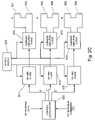
- FIG. 2Cis a block diagram of a system for driving electromagnet coils.
- FIG. 2Dis a matrix representation of the vector forming the GCI system.
- FIG. 2Eis a representation of a characteristic matrix in the GCI system.
- FIG. 2Fis a representation of the Inverse characteristic matrix shown in FIG. 2E above.
- FIG. 2Gis a representation of the product of the characteristic matrix with its Inverse matrix used in the GCI system.
- FIG. 2His a logical flow diagram of FIG. 2G .
- FIG. 2Iis a front view showing the magnet clusters, radar system, and optical sensor.
- FIG. 2Jis a side view showing the magnet clusters, the radar system, the optical sensor, the C-arm, and an operating table.
- FIG. 2Killustrates the radar system, the 6-DOF sensor, and a gimbaled motion mechanism on top of the C-arm.
- FIG. 2Lillustrates a “C” curve representation of Actual Position (AP) of the catheter tip and the Desired Position (DP).
- FIG. 3is a block diagram of the radar Phased-array Radar module and its associated electronics for measuring the position of the catheter.
- FIG. 3Aillustrates the use of the radar system in identifying the position and orientation of the catheter tip.
- FIG. 3Billustrates locating the catheter in a field of fiduciary markers.
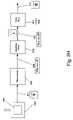
- FIG. 4is a block diagram of the 6-DOF sensor and its associated electronics for measuring the location of the fiduciary markers and synchronization of the image-capture.
- FIG. 5illustrates the use of the GCI apparatus with cineoangiographic equipment.
- FIG. 5Ashows how a fluoroscopy image and the synthetic image of the catheter from radar data are synchronized using the fiduciary markers and the 6-DOF sensor.
- FIG. 5Billustrates the use of the apparatus noted in 5 A while performing a pacemaker electrode implantation.
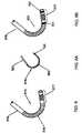
- FIGS. 6 and 6Aare perspective views of a catheter assembly and a guidewire assembly for use in the CGCI apparatus.
- FIG. 6Ba representation of a catheter fitted with a magnetic tip and two piezoelectric rings.
- FIG. 7is a graphical representation of the computational and a logical flow of the GCI system that includes the radar system and the 6-DOF sensor.
- FIG. 8is a functional block diagram of the signal flow in the CGCI apparatus.
- FIG. 9shows use of the catheter guidance system combination with a stereoscopic image produce by a bi-plane dual X-ray system.
- FIG. 10shows one embodiment of the 6-DOF sensor.
- FIG. 11is a perspective view showing capabilities of the Virtual Tip user input device.
- catheterizationis performed by inserting an invasive device into an incision or a body orifice. Secondary tools such as guidewires and balloons are often advanced through or over the primary catheter to the area where the medical procedure is to be performed. These procedures rely on advancing the distal end of the invasive device until the distal end reaches the destination area where the diagnostic or therapeutic procedure is to be performed.
- FIG. 1is a system block diagram for a surgery system 1500 that includes an operator interface 500 , a Catheter Guidance and Imaging (CGI) system 503 , surgical equipment 502 (e.g, a catheter tip 377 , etc.), one or more user input devices 900 , and a patient 390 .
- the user input devices 900can include one or more of a joystick, a mouse, a keyboard, a Virtual Tip 405 , and other devices to allow the surgeon to provide command inputs to control the motion and orientation of the catheter tip 377 ).
- the CGI system 503includes a controller 501 and an imaging and synchronization module 701 .
- the GCI System Controller 501calculates the Actual Tip (AT) position of a distal end of a catheter as further described in the text in connection with FIG. 7 .
- the GCI system controller 501uses data from the virtual tip (VT) 405 and the imaging and synchronization module 701 , the GCI system controller 501 determines the position error, which is the difference between the actual tip position (AP) and the Desired tip Position (DP).
- the controller 501controls electromagnets to move the catheter tip in a direction selected to minimize the position error.
- the GCI system 501provides tactile feedback to the operator by providing force-feedback to the VT 405 , as described in connection with FIG. 7 and FIG. 11 .
- FIG. 1Ais a block diagram of a system for surgery system 800 that represents one embodiment of the GCI system 503 .
- the system 800includes the controller 501 , a radar system 950 , a position sensor 960 , and (optionally) a gimbaled motion mechanism 970 .
- the sensor 960includes a six Degrees-of-Freedom (6-DOF) sensor as described in connection with FIG. 10 .
- the radar system 950can be configured as a ultra-wideband radar, an impulse radar, a Continuous-Wave (CW) radar, a Frequency-Modulated CW (FM-CW) radar, a pulse-doppler radar, etc.
- the radar system 950includes a phase-array antenna.
- the radar system 950uses Synthetic Aperture Radar (SAR) processing to produce a radar image.
- the radar system 950includes an ultra-wideband radar such as described, for example, in U.S. Pat. No. 5,774,091, hereby incorporated by reference in its entirety.
- the radar 950is configured as a radar range finder to identifying the location of the catheter tip.
- the 6-DOF sensor 960is configured to locate reference markers (fiduciary markers) placed on the patient. Data regarding location of the reference markers can be used, for example, for image capture synchronization.
- the motorized gimbaled and motion control mechanism 970allows the electromagnets of the to be moved relative to the patient 390 , as described in connection with FIG. 2K .
- Radarcan provide accurate dynamic position definition, which provides for real-time, high resolution, high fidelity signal. Radar is compatibility with strong magnetic fields. Self-calibration of range measurement can be based on time-of-flight or Doppler processing. Radar further provides for measurement of catheter position while ignoring “Hard” surfaces such as rib cage, bone structure, etc, as these do not interfere with measurement or hamper the accuracy of the measurement. In addition, movement and displacement of organ (pulmonary expansion and rib cage displacements as well as cardio output during diastole or systole) do not require an adjustment or correction of the radar signal. Radar can be used in the presence of movement since radar burst emission above 1 GHz can be used with sampling rates of 50 Hz or more, while heart movement and catheter dynamics occur at 0.1 Hz to 2 Hz.
- the use of radarreduces the need for complex image capture techniques normally associated with expensive modalities such as fluoroscopy, ultrasound, Hall Effect Sensors, magnetostrictive technology, or SQUID which require computational-intensive processing in order to translate the pictorial view and reduce it to a coordinate data set.
- Position data synchronization of the catheter tip and the organ in motionis readily available through the use of the radar.
- the radarcan be used with a phased-array or Synthetic Aperture processing do develop detailed images of the catheter locating in the body and the structures of the body.
- the radar systemincludes an Ultra Wide Band (UWB) radar with signal with a high resolution sweep range gate.
- UWBUltra Wide Band
- a differential sampling receiveris used to effectively eliminate ringing and other aberrations induced in the receiver by the near proximity of the transmit antenna.
- the radar systemcan detect the presence of obstacles of objects located behind barriers such as bone structures. The presence of different substances with different dielectric constants such as fat tissue, muscle tissue, water, etc, can be detected and discerned due to attenuation variation.
- the outputs from the radarcan be correlated with similar units such as multiple catheters used in Electro-Physiology (EP) studies while detecting spatial location of other catheters present in the heart lumen.
- the radar systemcan use a phased array antenna and/or SAR to produce 3-D synthetic radar images of the body structures, catheter tip, and organs.
- the location of the patient relative to the CGI systemcan be determined by using the 6-DOF sensor 960 to locate a plurality of fiduciary markers.
- the data from the sensor 960is used to locate the body with respect to an imaging system such that the catheter position data from the radar can be superimposed (synchronized) with the images produced by the imaging system.
- the ability of the radar and the 6-DOF sensor to accurately position the catheter tip relative to the stereotactic frameallows the CGCI electromagnet cluster to be moved by a gimbal system 970 so as to optimize the location of the magnet poles with respect to the patient and thus reduce the power needed to manipulate the catheter tip.
- FIGS. 2 , 2 A, and 2 Bshow a polar configuration of electromagnets used in the GCI apparatus 503 , with six coils 901 - 906 configured in flower-like structures, or clusters.
- the coils 901 - 903are configured as a cluster 920 mounted at the top of a C-arm 391
- the coils 904 - 906are configured as a cluster 930 mounted at the bottom of the C-arm 391 .
- the three coils 901 , 902 and 903 , forming the upper cluster 920are further shifted by 120 degrees relative to each other, as are the bottom three coils, 904 , 905 and 906 .
- the coils of cluster 920 at the top of the C-arm 391are also tilted downward somewhat, at an angle of 15 to 20 degrees, as are the coils of the bottom cluster 930 , of the C-arm 391 , tilted upward, as shown in FIG. 2B .
- the C-arm 391 support assemblyis configured to close the magnetic field circuit between the cluster 920 and the cluster 930 .
- the cluster 920 at the top of the C-armis rotated with respect to the bottom cluster by an angle of 60 degrees.
- An operating table 389is provided between the cluster 920 and the cluster 930 .
- the coils at the top of the C-arm 391are marked as 901 , 902 , and 903 , counting clockwise, and the bottom coils are marked 904 , 905 and 906 , counting in a counter clockwise direction.
- Coils 901 and 903work as a pair and are designated as the X-axis pair of coils
- coils 902 and 904work as another pair and are designated as the Y-axis pair of coils
- coils 905 and 906are the third pair and are designated as the Z-axis pair of coils (in this arrangement, the X, Y and Z coil axes are not orthogonal).
- FIGS. 2 , 2 A, and 2 Bprovide for relatively free access for the physician to the patient while the Z axis electromagnets 905 and 906 do not obstruct the available access space.
- FIG. 9shows an alternative embodiment using bi-plane rings. The embodiments of FIG. 2 and FIG. 9 are useful for accommodating imaging technologies such as X-ray, CAT-Scan, PET-Scan, Ultrasound, etc.
- the configuration shown in FIG. 9allows the use of a stereoscopic image through the use of a bi-plane set-up with dual X-ray sources.
- FIGS. 2 , 2 A and 2 Bprovide a geometry that is compatible with computer tomography systems and/or the imaging systems.
- the configurations shown in FIG. 9 and FIGS. 2 , 2 A and 2 Bprovide for advantages in mounting the operating interface equipment 500 , surgical medical equipment 502 , and portions of the GCI apparatus 501 .
- FIG. 2Cis a block diagram of the drive system for the coils 901 - 906 .
- the controller 530calculates a desired X-axis drive signal that is provided to an X-axis op-amp 911 .
- An output of the X-axis op-ampis provided to a current amplifier 910 .
- the current amplifier 910provides current to drive coils 901 and 903 in series. Alternatively, the coils 901 , 903 can be driven in parallel (not shown).
- the controller 530calculates a desired Y-axis drive signal that is provided to a Y-axis op-amp 913 .
- An output of the Y-axis op-ampis provided to a current amplifier 912 .
- the current amplifier 912provides current to drive coils 902 and 904 in series. Alternatively, the coils 902 , 904 can be driven in parallel (not shown).
- the controller 530calculates a desired Z-axis drive signal that is provided to a Z-axis op-amp 915 .
- An output of the Z-axis op-ampis provided to a current amplifier 914 .
- the current amplifier 914provides current to drive coils 905 and 906 in series. Alternatively, the coils 905 , 906 can be driven in parallel (not shown).
- a power supply 899provides power to the amplifiers 910 - 915 .
- the signals for the three channels, X, Y, and Z,can be expressed as a vector V 923 shown in FIG. 2D , having elements Vj x , Vj y and Vj z .
- the operatoruses the user input devices 900 such as the virtual tip 405 to command a movement in one or more axes. Signals from the user input devices 900 are provide to a computation module 922 . In a closed-loop system, tip position data from a sensor such as the radar sensor 950 is also provided to the computation module 922 . In an open-loop system, the tip position data is not necessarily provided.
- the computation module 922translates the position data and perform an Inverse operation on the matrix of the three signals for the three axes.
- the computation module 922multiplies the position vector V 923 by a matrix M-inverse, shown in FIGS. 2F and 2G as 927 , such that the output of the computation module 922 is M-inverse times V, where M is the characteristic matrix 925 of the cluster of coils 901 through 906 .
- the transformed X, Y, Z outputs from the computation module 922are provided to the respective amplifiers 911 , 913 , and 915 to generate the magnetic field and thereby move the catheter dip in the direction commanded by the operator.
- the transformation of inputs in an open-loop systemis shown in block diagram form in FIG. 2H , where the input signal V 931 is provided to an Mchar-Inverse module 932 .
- the module 932computes the matrix product Mchar-Inverse and the vector V to produce a transformed coordinate vector.
- the transformed coordinate vectoris provided to amplifier array 935 , that produces output currents that are provided to the respective current to the coils 901 - 906 .
- the coils 901 - 906produce the resulting field vector B 933 .
- the field vector B 933causes movement of the catheter tip, thereby translating the hand-movement of the clinician into the appropriate signal, and thus moving the catheter tip to the desired location.
- FIG. 2Kshows the radar system 950 , the 6-DOF sensor 960 , and a gimbaled motion mechanism 970 in relation to the C-arm 391 , the clusters 920 , 930 and the operating table 389 .
- the motion mechanism 970is configured to move the magnet cluster 920 to orient the cluster 920 in order to optimize (e.g, reduce) the power requirements for the operation of the electromagnets 901 - 906 .
- the mechanical arrangement shown in FIG. 2Kallows the GCI system 503 to be motion-controlled and gimbaled using motorized machinery 970 such as, for example, Computer Numeric Control (CNC) equipment.
- CNCComputer Numeric Control
- Use of the motorized gimbaled and computer-controlled mechanism 970substantially reduces the overall power requirement for the system, thereby enabling a desired magnetic field-strength to be achieved with less power.
- the desired magnetic field strengthis at least 0.3 Tesla.
- FIGS. 2K and 2Lillustrate the use of the motorized, gimbaled, and computer-controlled mechanism 970 to adjust the distance r 971 of the upper electromagnet cluster 920 relative to the lower electromagnet cluster 930 , so as to achieve an optimal power setting for the coils while maintaining a desired magnetic field strength.
- This procedureis achieved by first finding the location of the catheter tip 377 relative to the electromagnets by the use of the radar system 950 and synchronizing the position of the catheter tip 377 with fiduciary markers 700 Ax through 700 Bx (also referred to as reference markers 700 Ax through 700 Bx) by the use of the 6-DOF sensor 960 .
- the reference markers 700 Ax through 700 Bxare placed on the patient to provide reference points.
- This arrangementgenerates a mathematical manifold 701 (as described in connection with FIG. 7 ) over an image 702 generated by a fluoroscopic or other imaging system.
- the distance between the actual position (AP) 981 , of the catheter tip 377is marked by P 1 and the desired position (DP) 982 , set by the surgeon and is marked by P 2 .
- the difference between the two co-ordinates P 1 and P 2is a position error (PE) 983 .
- the force F and the resultant electromagnetic field Bare then calculated by the GCI controller 501 as described in connection with FIGS. 2C-2H . This process finds the position error (PE) 983 , which the controller 501 translates into the necessary current I for the coils 901 - 906 .
- the controllerthen changes the distance r 971 , and the angle ⁇ 984 , of the upper electromagnet cluster 920 relative to the lower electromagnet cluster 930 while the mechanism 970 is gimbaled and controlled, so as to set the distance r and the angle ⁇ 984 of the electromagnet clusters 920 relative to 930 in order to achieve an optimal power setting for the performance of GCI apparatus 503 .
- the controllerfeeds the electromagnets with the calculated current I to produce the desired movement of the catheter tip 377 .
- the “C” Curve 985is the line integral formed between point P 1 (the actual position (AP) 981 of the catheter tip 377 ) and point P 2 (the desired position 982 set by the operator/surgeon). The “C” curve 985 is then integrated with respect to the distance to calculate the force F necessary to move the catheter tip 377 from P 1 to P 2 .
- the line integral adjoining the two points in question, the actual position of the tip (AP) and the desired position (DP),is:
- the force F and the resultant electromagnetic field Bcorrespond to the appropriate current requirement I so as to achieve an optimal power setting in order to push, pull and rotate the catheter tip 377 thereby bringing it to its desired location.
- the only variableis the current vector I as the gimbal varies the value of the distance r 971 .
- FIG. 3is a block diagram of a radar system 1000 that can be used as one embodiment of the radar system 950 .
- the radar 1000 shown in FIG. 3includes a phased-array radar module 1100 having transmit/receive antenna elements and a Radio Frequency (RF) module 1150 .
- the radar system 1000includes the phased-array 1100 , an amplifier 1101 , an A/D converter 1102 , a Fast Fourier Transform module 1103 , and a microcontroller 1105 .
- the apparatusfurther includes a memory module in the form of RAM 1112 , and a look-up table in the form of a ROM 1111 .
- One embodimentincludes a voice messaging and alarm module 1110 , a set of control switches 1109 , and a display 1108 .
- the data generated by the radar system 1000is provided to the GCI apparatus 501 via communications port 1113 .
- the radar system 1000includes a phased-array and uses Microwave Imaging via Space-Time (MIST) beam-forming for detecting the catheter tip 377 .
- An antenna, or an array of antennasis brought relatively near the body of the patient and an ultra wideband (UWB) signal is transmitted sequentially from each antenna.
- UWBultra wideband
- the reflected backscattered signals that are received as radar echoesare passed through a space-time beam-former of the radar unit which is designed to image the energy of the backscattered signal as a function of location.
- the beam-formerfocuses spatially the backscattered signals so as to discriminate it from the background clutter and noise while compensating for frequency-dependent propagation effects.
- the significant contrast between the dielectric properties of normal tissue and the catheter tip 377formed out of a ferrite such as samarium-cobalt SmCo5, or neodymium-iron-boron, NdFeB, etc.), in the regions of interest, sufficient backscatter energy levels in the image to distinguish normal tissue from the catheter tip 377 , affording detection and discemability.
- a data-adaptive algorithmis used in removing artifacts in the received signal due to backscatter from the body tissue interface (e.g. the skin layer).
- One or more look-up tables containing the known dielectric constants of the catheter tip contrasted against the background dielectric information relative to the biological tissuecan be used to identify features in the radar image.
- the physical basis for microwave detection of the catheter tip 377 in the biological tissueis based on the contrast in the dielectric properties of body tissue versus the signature of the catheter tip 377 .
- the contrast of the dielectric values of biological tissue versus that of the catheter tipis amplified, filtered and measured.
- the catheter tip 377has a microwave scattering cross-section that is different relative to biological tissue of comparable size, relative to their dielectric properties, which is indicated by greatly different back-scatter energy registered by the receiver, and processed so as to afford a pictorial representation on a monitor 325 (shown in FIG. 5 ), with a significant contrast between the two mediums.
- the pictorial view of the catheter tip 377 generated by the radar system 1000can be superimposed over an X-ray fluoroscopy image and its coordinate data set linked to the GCI controller 501 for use by the position servo feedback loop.
- microwave imaging via space-time (MIST) beam-formingis used for detecting backscattered energy from the catheter tip 377 while the background is biological tissue.
- the radar system 1000detects the presence and location of various microwave scatterers, such as the catheter tip 377 , embedded in biological tissue.
- the space-time beam-formerassumes that each antenna in an array transmits a low-power ultra-wideband (UWB) signal into the biological tissue.
- the UWB signalcan be generated physically as a time-domain impulse or synthetically by using a swept frequency input.
- the radar system 1000uses a beam-former that focuses the backscattered signals of the catheter tip 377 so as to discriminate against clutter caused by the heterogeneity of normal tissue and noise while compensating for frequency-dependent propagation effects.
- the space-time beam-formerachieves this spatial focus by first time-shifting the received signals to align the returns from the targeted location.
- One embodiment of the phased-array radar 1000forms a band of finite-impulse response (FIR) filters such as high dielectric doping in the antenna cavity, forming the reference signal, where the doping is relative to the device of interest.
- FIRfinite-impulse response
- the signals from the antenna channelsare summed to produce the beam-former output.
- a technique such as weights in the FIR filterscan be used with a “least-squares fitting” technique, such as Savitzky-Golay Smoothing Filter, to provide enhancement of the received signal and to compute its energy as a function of the dielectric properties versus the scattered background noise of body tissue, thereby providing a synthetic representation of such a signal.
- the systemcan distinguish differences in energy reflected by biological tissues and the catheter tip 377 and display such energy differences as a function of location and co-ordinates relative to the fiduciary markers 700 Ax through 700 Bx, thereby providing an image proportional to backscattered signal strength, which is further used by the GCI controller 501 in computing the position co-ordinates and orientation of the catheter tip 377 relative to the stereotactic framing of the fiduciary markers.
- the details of the formation of the co-ordinates settings of the catheter tip 377 relative to the stereotactic frame and the synchronization of such image with the fluoroscopy frame 702is further described in connection with FIGS. 5 and 5A .
- the radar module 1000uses an FFT algorithm 1103 which uses a filtering technique residing in look-up tables 1111 to allow the radar sensor 950 to discern varieties of dielectric properties of specific objects known to be used in a medical procedure, such as a guide-wire 379 and/or a catheter 953 with piezo-electric ring 951 , 952 , so as to afford differentiation of various types of instruments like catheters, guide-wires, electrodes, etc.
- FFT algorithm 1103uses a filtering technique residing in look-up tables 1111 to allow the radar sensor 950 to discern varieties of dielectric properties of specific objects known to be used in a medical procedure, such as a guide-wire 379 and/or a catheter 953 with piezo-electric ring 951 , 952 , so as to afford differentiation of various types of instruments like catheters, guide-wires, electrodes, etc.
- FIG. 3Ais a graphical representation of the catheter tip 377 embedded with one or two piezoelectric rings 951 , 952 such as Lead-Zirconate-Titanate (PZT) and/or molecularly conjugated polymers such as switchable diodes (polyacetylene).
- the second harmonics generated by the rings 951 , 952provide an identifiable return signature in the second harmonic due to the non-linearity of the material. While the fundamental harmonic (e.g. 5 MHz) is transmitted by the radar, the second harmonic (e.g. 10 MHz) is readily distinguishable by the radar system 1000 .
- the radar system 1000can discern between the catheter tip (which is formed out of ferrite such as samarium-cobalt SmCo5, or neodymium-iron-boron, NdFeB) and the PZT rings 951 and 952 .
- the ability to distinguish between the signal return from catheter tip 377 and the PZT rings 951 , 952allows the radar system 1000 to filter out the background clutter received from the body tissue and recognize the position and orientation of the rings 951 , 952 , and the position co-ordinates of the catheter tip 377 .
- the technique of using two different dielectric properties and electrical characteristic of the tip 377 versus the PZT 951 and 952provides the catheter tip 377 with a radar signature that is unique and readily recognized by the radar system 1000 .
- FIG. 3Afurther illustrates how the radar system 1000 with its transmit and receive antennas is used to detect the position co-ordinates and orientation of catheter tip 377 relative to its two PZT rings 951 and 952 .
- a geometrical manipulationis employed by the radar system 1000 and its associated FFT filter 1103 by the resident microcontroller 1105 .
- a catheter-like deviceis provided with a magnetically-responsive tip 377 .
- the tip 377includes a permanent magnet.
- the polarity of the permanent magnetis marked by two PZT rings where the north pole is indicated by a PZT ring 952 and the distal end of the ferrite where the semi-flexible section 953 of the catheter 376 is marked with the additional PZT ring 951 , also marking the south pole of the ferrite.
- the radar system 1000transmits burst of energy that illuminates the ferrite catheter tip 377 .
- the return signal from the catheter tip 377is received by the radar and its position is registered by observing the time of flight of the energy, thereby determining the location of the catheter tip 377 as position co-ordinates in a three-dimensional space.
- the radar detector 1000is also capable of discerning the location of the tip 377 relative to the two PZT rings so as to afford a measurement of PZT ring 952 relative to the second piezo-electric ring 951 with reference to the position co-ordinates of catheter tip 377 .
- the radar detector 1000can discern the return signal from PZT rings 952 and 951 due to the non-linear characteristic of PZT material that generates a second harmonic relative to the incident wave. By comparing the strength of the fundamental frequency and the second harmonic, the radar system 1000 is able to discern the position and orientation of the two PZT rings relative to the ferrite 377 , thereby providing position and orientation of the catheter tip 377 .
- FIGS. 3B , 5 and 5 Billustrate the technique of measuring the position and orientation of the catheter tip by the use of the radar detector 1000 and using the fiduciary markers 700 Ax and 700 Bx to form a frame of reference for the catheter dynamics such as movement relative to the frame of reference.
- the fiduciary markers 700 Ax and 700 Bxform a manifold 701 .
- the locations of the markers 700 Ax and 700 Bxare measured by the 6-DOF sensor
- FIG. 4is a block diagram of a 6-DOF sensor system 2100 that is one embodiment of the 6-DOF sensor 960 .
- the system 2001includes a 6-DOF optical sensor 2100 and its associated electronics for measuring the location of the fiduciary markers 700 A 1 , 700 A 2 , 700 A 3 , and 700 A 4 , and 700 B 1 , 700 B 2 , 700 B 3 , and 700 B 4 , located on the patient's body 390 to define a stereotactic frame. As shown in FIG.
- the 6-DOF optical sensor 2100is described in more detail in connection with FIG. 10 .
- the system 2000includes the 6-DOF optical sensor 2100 , an instrumentation amplifier 2101 , an A/D converter 2102 , a Fast Fourier Transform module 2103 , and a microcontroller 2105 .
- One embodimentincludes a voice massaging and alarm module 2110 , a set of control switches 2109 , and a display 2108 .
- Data generated by the 6-DOF sensor 2000is provided to the GCI apparatus 501 via a communications port 2113 .
- FIG. 5illustrates a general connection of the GCI apparatus 501 to cineoangiographic equipment 502 .
- the cineoangiographic equipment 502is interfaced with the GCI apparatus 501 through the operator interface equipment 500 .
- the cineoangiographic image of an arterial treeis shown on the video monitor 325 , with the position of catheter tip 377 superimposed onto the image.
- the imagewill be referred to herein as a flouroscopy image, it being understood that the image can be generated by any technology that can generate images of the body structures, including, but not limited to, X-ray imaging, Fluoroscopy, ultrasonic imaging, MRI, CAT-Scan, PET-Scan, radar imaging, etc.
- the display of these imagesis synchronized by the use of the 6-DOF sensor and its accompanying fiduciary markers 700 A 1 , 700 A 2 , 700 A 3 , and 700 A 4 , and 700 B 1 , 700 B 2 , 700 B 3 , and 700 B 4 , located on the patient's body 390 so as to locate a stereotactic frame that provides for the referential markers and enables the synchronization 701 of the image 702 shown on video monitor 325 , with the position of the catheter tip 377 .
- FIG. 5Aillustrates how the image 702 and the synthetic image of the catheter 377 obtained from the radar system 950 are superimposed together on monitor 325 and synchronized using the 6-DOF sensor 2000 and the fiduciary markers 700 A 1 , 700 A 2 , 700 A 3 , and 700 A 4 , and 700 B 1 , 700 B 2 , 700 B 3 , and 700 B 4 , located on the patient's body 390 .
- FIG. 5Afurther illustrates the formation of a stereotactic frame 701 in support of position definition of the catheter tip 377 relative to the frame 701 .
- This methoduses fiduciary markers formed as an approximate cube and detected by the 6-DOF sensor 2100 .
- the entire data set formed as a manifold 701includes a set of the image 702 , radar image data of catheter tip 377 (such as, for example, data from the radar system 1000 ), and the fiduciary markers 700 Ax through 700 Bx.
- the beating heart and its cardio-output, the pulmonary expansion and contraction, or a spasm of the patientall these can be dynamically captured and linked together so as to achieve a substantial motion in unison between the catheter's tip and the body organ in question.
- FIG. 5Afurther illustrates the image capture technique of superimposing the fiduciary markers 700 A 1 , 700 A 2 , 700 A 3 , 700 A 4 , 700 B 1 , 700 B 2 , 700 B 3 , and 700 B 4 onto the fluoroscopic/ultrasonic image 702 , generated as shown in the image in FIG. 5 .
- the scheme providedidentifies the dynamic location of the catheter tip 377 with reference to the image 702 .
- the referential frame 701 formed by the fiduciary markers 700 Ax and 700 Bx and utilizing the 6-DOF sensor 2000defines the catheter's tip position relative to the stereotactic frame 701 .
- this methodprovides for a synchronized image-capture relative to the catheter tip 377 thereby affording the superimposition of the image 702 relative to both the fiduciary markers 700 Ax and 700 Bx and the catheter tip 377 on a dynamic basis, hence, providing position definition with a frame of reference, noted in FIG. 5A as 701 .
- FIG. 5Ashows the use of the synchronization algorithm 701 whereby the space formed by the fiduciary markers 700 A 1 , 700 A 2 , 700 A 3 , 700 A 4 , 700 B 2 , 700 B 3 , and 700 B 4 is represented by an n-dimensional space where each of the fiduciary markers 700 Ax and 700 Bx is denoted by a vector f i ⁇ f 1 , f 2 . . . f n ⁇ and the catheter tip 377 position data provided by the radar 1000 are designated by a function g i ⁇ g 1 , g 2 . . . g n ⁇ .
- the length of the vector f, g in an n-dimensional spaceis defined by
- the 6-DOF 2000 sensor with its position data set as a vector function f i and the position data set of the catheter tip 377 generated by the radar system 1000 and denoted by vector function g iare orthogonal and their distance is shown by the difference noted in equation (2) and its relative orientation is shown by equation (3).
- the manifold 701 defining the location of the catheter tip 377 relative to the fiduciary markers 700 Ax- 700 Bxis therefore the difference between vector function f i to vector function g i relative to the angle and mapped over time domain T, where T is ⁇ t 1 , t 2 . . . t n ⁇ .
- the optimal power settingis generated by the electromagnet clusters 920 and 930 with respect to the distance r 971 , and angle ⁇ 984 , relative to the catheter tip 377 .
- FIG. 5Bshows the use of the apparatus described in FIG. 5A while performing a pacemaker electrode implantation.
- FIG. 5Bfurther illustrates the implantation of cardiac pacemaker 801 with electrodes as shown, placed in an area relative to the S.A. Node 802 , A.V. Node 803 , and a bundle of His 804 . Further illustrated are the right and left bundle branches 805 .
- Pacemaker implantationis essential for the survival of patients with heart rhythm or electrical conduction disturbances. This procedure is performed by the implantation of a small electrode in the heart cavity wall (ventricle or atrium). The other end of the electrode is attached to an electronic device 801 which is implanted under the chest skin and which generates stimulation pulses to simulate the heart rhythm.
- Similar devicesapply electrical shock when life threatening heart electrical disturbances are detected by the electrodes Automatic Implantable Cardiac Defibrillator (AICD). These electrodes are placed through a vein by pushing and manipulating under fluoroscopy. Through the use of the apparatus GCI 501 , guidewire 379 fitted with magnetic tip 381 is used to carry and place the electrodes of pacemaker 801 in their proper position by using the CGI system.
- AICDAutomatic Implantable Cardiac Defibrillator
- the physiciannavigates the guidewire 379 through the heart lumen while having a continuous dynamic referential frame identifying the guidewire tip 381 using the position data from radar 1000 and the employment of the 6-DOF sensor 2000 as shown in FIG. 5 and further illustrated by FIG. 5A .
- the manipulation to place the electrodes in the proper positionis difficult and the results are sub-optimal due to anatomical variations.
- controller 501provides simplicity in performing such a complex operation while the physician is capable of moving, pushing, and placing the electrodes of pacemaker 801 in its desired anatomical position without compromise due to the inability of navigating, guiding, controlling, and imaging the movement of the guidewire and the pacemaker electrodes accurately.
- FIGS. 6 and 6Aare perspective views of a catheter assembly 375 and a guidewire assembly 379 for use with the GCI system 503 .
- the catheter assembly 375is a tubular tool that includes a catheter body 376 which extends into a flexible section 378 that possesses increased flexibility for allowing a more rigid responsive tip 377 to be accurately steered through a torturous path.
- the magnetic catheter assembly 375 in combination with the GCI apparatus 501reduces or eliminates the need for the plethora of shapes normally needed to perform diagnostic and therapeutic procedures.
- the GCI apparatus 501By using the GCI apparatus 501 , only a single catheter is needed for most, if not all patients, because the catheterization procedure is now achieved with the help of an electromechanical system that guides the magnetic catheter and guidewire assembly 375 and/or 379 to the desired position within the patient's body 390 as dictated by the surgeon's manipulation of the virtual tip 405 , without relying on the surgeon pushing the catheter quasi-blindly into the patient's body 390 .
- the magnetic catheter and guidewire assembly 375 , 379provides the flexibility needed to overcome tortuous paths.
- the guidewire assembly 379includes guidewire body 380 and a flexible section 382 , which possesses increased flexibility for allowing a more rigid responsive tip 381 to be accurately steered around sharp bends so as to navigate a torturous path.
- the responsive tips 377 and 381 of both the catheter assembly 375 and the guidewire assembly 379 respectively,include magnetic elements such as permanent magnets.
- the tips 377 and 381include permanent magnets that respond to the external flux generated by the upper electromagnetic cluster 920 and the lower electromagnetic cluster 930 .
- the tip 377 of the catheter assembly 375is tubular, and the responsive tip 381 of the guidewire assembly 379 is a solid cylinder.
- the responsive tip 377 of the catheter assembly 375is a dipole with longitudinal polar orientation created by the two ends of the magnetic element positioned longitudinally within it.
- the responsive tip 381 of guidewire assembly 379is a dipole with longitudinal polar orientation created by the two ends of the magnetic element 377 positioned longitudinally within it.
- FIG. 6Bis a representation of a catheter fitted with a magnetic tip and two piezoelectric rings.
- FIG. 6Bfurther illustrates an added improvement of the catheter assembly 375 and guide-wire assembly 379 to be used with the GCI system 503 , with the exception that catheter assembly 953 is fitted with an additional two piezoelectric rings or polymer of semi-conducting properties, 951 and 952 , located as shown.
- the radar system 950in combination with the controller 501 provides an additional detection modality of the catheter tip whereby an RF signal is emitted so as to excite the two piezoelectric rings or the polymer and thus provide a measure of rotation of the catheter tip relative to the north pole of the magnet 377 .
- the GCI system 503can define the angle of rotation of the tip 377 and in a more elaborate scheme known to those familiar with the art the piezoelectric rings or polymer 951 , 952 , can provide additional position information to define the position, orientation, and rotation of the catheter tip 377 relative to the stereotactic framing 701 as described in FIGS. 5 , 5 A, and 5 B.
- FIG. 7illustrates a logical computational flow performed by the system controller (SC) 501 for determining the position of the actual catheter tip (AP) 377 .
- the controlleralso combines catheter tip position data (measured by the radar system 950 ) with the fiduciary markers position data (measured by the 6-DOF sensor 960 ) to determine the position of the catheter tip in the body of the patient and to synchronize the catheter position with image data (if available).
- the controller 501sends feedback data to the Virtual Tip (VT) 405 to provide tactile feedback if the position error (PE) 983 exceeds a predetermined amount in a predetermined time in any axis or axes, thereby notifying the operator of an obstruction encountered by the catheter tip 377 . It is assumed that if the (PE) 983 is not eliminated by the normal operation of the GCI apparatus 501 within an expected amount of time or cycles of steps 1 through 14 above, then an obstacle is likely to have been encountered by the actual catheter tip 377 . This is perceived by the operator through tactile feedback generated by a resistance on the stick and acting on one or more of the user input devices 900 such as the virtual tip 405 .
- FIG. 8is a functional block diagram of the signal flow in the CGCI apparatus.
- the figureillustrates the operation of the virtual tip 405 , which provides intuitive joystick-type control of the catheter tip by the surgeon.
- the surgeonpushes, pulls, or rotates the virtual tip 405 in the desired direction so as to cause a similar movement of the catheter tip 377 within the patient's body 390 .
- the virtual tip 405responds with tactile feedback in the form of resistance to movement in the appropriate axis or axes.
- the surgeoncan “feel” the actual tip as it is advancing.
- tip 405is released, the catheter tip 377 is forcefully held in its current position.
- System Controller of GCI 501correlates the actual tip position (AP) 981 with cardio-position data (CP) obtained from the manifold 701 and generated by the radar 950 and the 6-DOF sensor 960 . These data sets are superimposed on fluoroscopic image 702 generated by auxiliary equipment 502 , and displayed on monitor 325 with the combined and synchronized tip and X-ray imagery formed as manifold 701 .
- the display of the three-dimensional actual tip position (AP) 981is continuously updated on a real-time basis with the AP data. Relatively fewer frames of X-ray imagery are used to overlay the display with CP data.
- FIG. 8further describes the operation of the GCI apparatus 501 by showing the procedure wherein the hand motion of the surgeon operating the user input devices 900 (such as the virtual tip 405 ) is captured and translated into movement command.
- An optimization of the power versus force required to move the catheter tip 377 while using the amplifiers 910 through 915 to generate the necessary currents for the coils 901 through 906is provided.
- the coilsproduce a B field at the tip of catheter 377 , responding to the force/torque generated at the tip 377 according to Maxwell's equations.
- the movement of the catheter tip 377is monitored in real time by the radar system 950 , where tip position and orientation information are displayed through a process of synchronization 701 using the fiduciary markers 700 Ax through 700 Bx through the use of the 6-DOF sensor 2000 , thereby gating the position as well as the reflected force/torque generated by the actual tip.
- This processcontinuously repeats itself so as to respond to the operator's movement by the use of the user input devices 900 .
- FIG. 8is clear and intuitive to those familiar with the art and is further detailed in FIGS. 1 through 7 .
- the processis described as follows: i) the operator adjusts the physical position of the virtual catheter tip 405 to a desired position, ii) a change in the virtual tip 405 position is encoded in the controller 501 , producing new position data from the radar 950 which too is received at the controller 501 , iii) the controller 501 generates commands sent to a servo system control module, iv) the servo system control module controls the gimbal and motion control apparatus 970 to adjust the position of the coils 901 through 906 to optimizing the position of the electromagnet clusters 920 relative to 930 , by varying the distance r 971 , and the angle ⁇ 984 of the electromagnet clusters, v) current is sent to the coils 901 - 906 causing the position of the actual magnetic catheter tip 377 within the patient's body 390 to change, vi) the new position of the actual catheter tip (AP) is then sensed by the radar system 950 and the 6-DOF sensor
- FIG. 9shows the arrangement of electromagnetic coils 132 X, 132 Y, 132 Z, 138 X, 138 Y, and 138 Z in a polar configuration, 374 that illustrates the use the GCI apparatus 503 with an alternate magnet system using a bi-plane X-ray support mechanism, as opposed to the arrangement noted in FIG. 2 as the “C”-arm 391 layout.
- FIG. 9further illustrates the overall relationship between the elements comprising the GCI apparatus 501 , which includes an operating table 389 , the patient 390 , a T-axis encoder 394 , a trunnion 388 , a support assembly 385 , a polar support 391 .
- FIGS. 2 , 2 A, and 2 Bare advantageous as the strength of the electromagnetic field B increases towards the center line of the gap, and the gradient peaks at the edge of the gap, enabling the GCI 501 to form a lobed magnetic field structure which is not as easily obtainable by the use of the Bi-plane axio-symmetric layout noted in FIG. 9 .
- the GCI 501incorporates such an arrangement so as to provide the benefits of pushing, pulling and guiding the magnetically coupled catheter tip 377 in a polar configuration such as the one noted in FIG. 9 .
- the apparatususes a T-axis encoder 394 and the G-axis encoder 393 which provide the system with gantry position information for use in calculating the required coordinate rotation prior to energizing the electromagnets.
- the polar configuration 374uses the trunnion 388 which acts as a truss for the support assembly 385 .
- Polar support 391 . 1pivots on the G-axis of support assembly 385 , and the polar assembly 391 . 1 supports the X-ray source 383 and X-ray image intensifier 384 which produce the X-ray images that are superimposed together with the actual catheter tip position on the monitor 325 .
- Polar support 391 . 1provides a mounting surface for electromagnets 132 X, 132 Y, 132 Z, 138 X, 138 Y, and 138 Z in their appropriate coaxial arrangements.
- the trunnion 388is centered on the T-axis 387 .
- the T-axis encoder 394is mechanically coupled to the trunnion 388 in order to encode positional data of the support assembly 385 in the T-axis.
- a gimbal-axis (G-axis) 386intersects with the T-axis 378 at the center point of the polar support 391 . 1 . This center point coincides with the center point of the X-ray field of view.
- a G-axis encoder 393is mechanically coupled to the support assembly 385 along the G-axis 386 .
- the 6-DOF sensorprovides the sensing of six degrees of freedom (DOF) relative to the fiduciary markers. It accomplishes this by emitting a laser beam and detecting the reflection off the markers. Inside the sensor, the beam is split and directed onto three photo diodes. The analog signals from the diodes are digitized and fed into a computer which can instruct corrective action for a machine or output position readings.
- DOFdegrees of freedom
- FIG. 10shows the 6-DOF sensor wherein a laser source 2012 illuminates mirrors 2014 , 2016 to guide a beam 2018 to the primary optical axis of the sensor.
- the beamis passed through two negative lenses ( 2020 and 2022 ) which diverge the beam.
- the divergence angleis approximately 0.3 radians (half angle) to produce 1 cm diameter laser spot at about 3.5 cm from the face of the sensor. Other divergence angles can be used as well.
- the sensor's field of viewcan be changed by choosing different negative lenses 2020 , 2022 which in turn change the divergence angle and spot size at a given distance.
- Two reflective reference markerse.g., a 4 mm diameter dot 2024 and a 1 ⁇ 1 mm bar 2026 , are mounted on non-reflective tape and applied to the patient.
- the laser lightreflects off the markers and back into the sensor. Because the beam is diverging, the reflections are magnified in area when the light returns to the sensor, allowing most of the light to go around the small negative lenses and through a relatively large positive lens instead.
- Lens 2019has a hole in its center to pass the outgoing beam 2018 , but has a focal length which collimates the diverging reflection beam.
- the positive focal length off lens 2019is the same as the negative focal length of the lenses 2020 and 2022 by bending the diverging rays of reflected light from the dot 2024 to enter the sensor in parallel when the dot is located around half that focal length from the sensor.
- the filter 2030passes the laser light but blocks light at other wavelengths.
- light from the dot 2024is divided into two beams by a beam splitter 2032 .
- Half of the beamis reflected 90 degrees into lateral effect photo diode 2034 .
- the other half of the beampasses through the beam splitter, into a positive lens 2036 , off mirrors 2040 and 2041 , and onto another photo diode 2038 .
- Light from bar 26also passes through the filter 2030 .
- the laser light that reflects from itis at a greater angle of divergence.
- the greater angle of reflectioncauses the light to pass through a different location of the filter 2030 , missing lens 2019 and the beam splitter and illuminating photo diode.
- a light emitting diode 2023can be installed inside the sensor to provide controlled background light.
- Each of the three photo diodes ( 2034 , 2038 and 2042 )has different sensitivity to the relative position of the sensor and the reflectors ( 2024 and 2026 ), permitting any change in position in any of the six degrees of freedom to be delineated when decoupling in software.
- the photo diode 2042is sensitive to translation between the bar 2026 and the sensor (Tz) and the rotation of the sensor about the axis normal to the surface (Rz) of dot 2024 .
- the bar 2026is tilted such that its reflection illuminates the center of photo diode 2042 if the sensor is at a prescribed stand-off distance from the bar 2026 (half the focal length of 2019 ).
- any up-down deviation of the bar's reflection from the center of photo diode 2042can be calculated as a distance of the sensor from the bar (Tz).
- the radial location of the bar relative to the center of the dotis used as a reference for rotation about Rz. Consequently, right-left deviation of the bar's reflection from the center of photo diode 2042 can be calculated as rotation of the sensor about the normal axis of the dot (Rz).
- photo diode 2038is most sensitive to tilt about the X and Y axis (Rx, Ry) as explained below. Because the laser beam is diverging as it strikes the reflective reference marker 2024 , the reflected beam returns larger but on center with the negative lenses 2014 , 2016 even when the sensor is tilted about the negative lenses, i.e., the return light enters the sensor perpendicular to the surface of the reference dot, regardless of sensor tilt. Although the light returns as before the tilt, the position of photo diode 2038 does change with tilt of the sensor. Consequently, during tilt, motion of photo diode 2038 relative to an unchanged focus of the reflected light provides sensitivity to tilt about the X and Y axis (Rx, Ry).
- diode 2038is not sensitive to pure translations of the reflector 2024 because a lens focuses all parallel rays passing through it to the same point, regardless of where the ray comes from, i.e., regardless of where the marker is translated.
- photo diode 2034In the case of photo diode 2034 , the beam splitter 2032 reflects the light onto it without a lens in the path. Consequently, unlike diode 2038 , diode 2034 is sensitive to lateral translation of the sensor relative to the reference dot (Tx, Ty). Photo diode 34 is also sensitive to tilt; however, this effect can be canceled in software using information from photo diode 38 . Likewise, any coupling of photo diodes 42 with the other two photo diodes can be canceled in software.
- the analog data from the diodesare digitized with an Analog to Digital converter and provided to a computer for processing as two channels from each of the three photo diodes.
- the datadoes not represent pure motions about the six axes because all but two of the channels have information on more than one motion, i.e. the channels are coupled.
- the informationcan be decoupled into pure measurements of motion about all six degrees of freedom. This decoupling is possible because each photo diode provides different information.
- Photo diode 38is sensitive only to tilt about the X and Y axis (Rx and Ry). Therefore, the voltage readings from these channels represent pure tilt in those axes without sensitivity (coupling) to other motions.
- photo diode 34is sensitive to four axes of motion, rotation and translation about X and Y (Tx, Ty, Rx & Ry). However, by subtracting any voltage reading from the photo diode 38 , the tilt sensitivity of photo diode 34 is negated, and the remaining voltage is representative of only translation about X and Y (Tx, Ty). Likewise, photo diode 42 is sensitive to all six degrees of freedom. But, by subtracting the voltage from the other two photo diodes, the remaining voltage is representative of only rotation and translation about the Z axis (Tz, Rz).
- the datacan be displayed to the operator and/or provided to the CGI system.
- the Six DOF sensoris capable of tracking all 6 degrees of freedom. Because the laser beam diverges, reflections from the markers are magnified on the photo diodes, increasing accuracy. This benefit, combined with high-resolution A to D converters provides micron accuracy in detecting translation and milliradian accuracy in detecting orientation. With different optics, field of view can be reduced to improve accuracy and visa versa.
- the markersconform to the contour of the body, so positioning the reflective markers (references) on the body is a 3-DOF task (Tx, Ty, Rz) that can be performed by the operator or a simple 3-axis computer-controlled machine.
- the 6-D)F sensoris non-contact and non-surface dependent As an optical sensor, it does not physically contact the body.
- the 6-DOF sensoruses lateral-effect photo diodes rather than a camera. Since photo diodes are smaller than a camera, the 6-DOF sensor is relatively smaller than a camera-based system.
- FIG. 11is a perspective view showing capabilities of the Virtual Tip user input device 405 .
- the Virtual Tip 405is a multi-axis joystick-type device that allows the surgeon to provide inputs to control the position, orientation, and rotation of the catheter tip 377 .
- the Virtual Tip 405includes an X input 3400 , a Y input 3404 , Z input 3402 , and a phi rotation input 3403 for controlling the position of the catheter tip.
- the Virtual Tip 405further includes a tip rotation input 3405 and a tip elevation input 3404 . As described above, the surgeon manipulates the Virtual Tip 405 and the Virtual Tip 405 communicates the surgeon's movements to the controller 501 .
- the controller 501then generates currents in the coils to effect motion of the actual catheter tip 377 to cause the actual catheter tip 377 to follow the motions of the Virtual Tip 405 .
- the Virtual Tip 405includes various motors and/or actuators (e.g., permanent-magnet motors/actuators, stepper motors, linear motors, piezoelectric motors, linear actuators, etc.) to provide force feedback to the operator to provide tactile indications that the catheter tip 377 has encountered an obstruction or obstacle.
- the sensor that senses the position of fiduciary markersis described in embodiments as a 6-DOF sensor.
- a reference markere.g., a camera
- non-optical sensorssuch as radar, ultrasonic sensors, and the like can be used to detect the position of the fiduciary markers.
- the radar system 950can be used in place of the 6-DOF sensor 960 to detect radar-reflective fiduciary markers.
- the modulation of the electromagnetscan be controlled in such a way as to cause a vibratory or pulsating motion of the tip to aid in crossing plaque.
- the responsive tip(s)can be electromagnetic rather than permanent magnets.
- the magnetic field external to the bodycan be generated by a permanent magnet or magnets.
- the control of the external magnetic fieldcan be accomplished by manually administering the field generating devices.
- AC induction with its associated magnetic effectscan be used by causing a coil or coils wound around the tip to respond to an impressed time variant field.
- Materials with Curie temperatures within a few degrees of body temperaturecan be used as magnetic flux switches for selective tip control by irrigating them with fluids having appropriate temperatures; electrostatic phenomena can enhance magnetic effects.
- Artificial intelligencecan replace the operator control for producing command inputs; an expert system can replace or augment operator inputs.
- the apparatuscan be used to incubate various body cavities and organs other than the heart.
- the apparatuscan be used for human and animal procedures such as egg harvesting and embryo implantation.
- the responsive tipcan be attached to a coherent fiber optic bundle to provide viewing of internal structures with unprecedented maneuverability,
- Internal radioisotope therapycan be precisely performed by delivering a palletized source directly to a tumor using a guided catheter.
- Internal tissue samplescan be obtained without major surgery; a fiber optic light guide equipped with a responsive tip can be accurately positioned to deliver laser light to a specific internal location without major surgery.
Landscapes
- Life Sciences & Earth Sciences (AREA)
- Health & Medical Sciences (AREA)
- Engineering & Computer Science (AREA)
- Surgery (AREA)
- Animal Behavior & Ethology (AREA)
- Veterinary Medicine (AREA)
- Pathology (AREA)
- Biomedical Technology (AREA)
- Heart & Thoracic Surgery (AREA)
- Medical Informatics (AREA)
- Molecular Biology (AREA)
- Physics & Mathematics (AREA)
- Biophysics (AREA)
- General Health & Medical Sciences (AREA)
- Public Health (AREA)
- Human Computer Interaction (AREA)
- Nuclear Medicine, Radiotherapy & Molecular Imaging (AREA)
- Optics & Photonics (AREA)
- Radiology & Medical Imaging (AREA)
- Media Introduction/Drainage Providing Device (AREA)
- Magnetic Resonance Imaging Apparatus (AREA)
- Ultra Sonic Daignosis Equipment (AREA)
- Measurement And Recording Of Electrical Phenomena And Electrical Characteristics Of The Living Body (AREA)
- Apparatus For Radiation Diagnosis (AREA)
- Radar Systems Or Details Thereof (AREA)
- Electrotherapy Devices (AREA)
- Geophysics And Detection Of Objects (AREA)
Abstract
Description
The sum on the space is taken by the integral
further the distance between the point f (fiduciary markers) and g (
thus
and in thus
since fiand giare orthogonal
- 1. The
controller 501 inhibits the outputs of the X-axis controller and amplifier (XCA)911 and910, the Y-axis controller and amplifier (YCA)913 and912, and the Z-axis controller and amplifier (ZCA)915 and914. - 2. The
controller 501 reads data from theradar system 950, identifying the actual position (AP)981 of thecatheter tip 377. - 3. The
controller 501 reads data from theuser input devices 900 for a new desired position (DP)982 of the catheter tip as directed by the surgeon. - 4. The
controller 501 performs the mathematical solution for the “C”curve 985. - 5. The
controller 501 reads the data from the 6-DOF sensor, denoting the position of the fiduciary markers700Ax,700Bx which form the stereotactic frame. - 6. The
controller 501 obtainsdigital image data 702 from theimage source 502. - 7. The
controller 501 synchronizes the data from of thecatheter tip position 377 with the data obtained from the 6-DOF sensor and arranges the combined data in the form of amanifold 701. - 8. The
controller 501 superimposes the manifold701 onto the digital image obtained from theimage source 702. - 9. The
controller 501 computes the optimal distance r971 and theangle Φ 984 of theelectromagnet clusters electromagnet clusters patient 390. - 10. The
controller 501 repeatssteps 1 through 9 above as necessary. - 11. The
controller 501 calculates an error position (PE)983 which is the difference between the actual position (AP)981 and the desired position (DP)982 of thecatheter tip 377, also denoted as curve “C”985 inFIG. 2L and represented by expression (PE=[AP−DP]). - 12. The
controller 501 repeats the process of optimal power setting algorithm so as to afford a geometry which accommodates the travel between the actual position of thecatheter tip 377 and the desired position of the tip set by the surgeon. - 13. The
GCI controller 501 commands theupper electromagnet cluster 920, using the motorized gimbaled and computer controlledapparatus 970, to move in such a manner so as to obtain an optimal configuration for the electromagnet system. - 14. The
controller 501 inputs the corrected magnetic field data as described by the procedure identified byFIGS. 2C through 2H to the X-axis controller and amplifier (XCA)911 and910, the Y-axis controller and amplifier (YCA)913 and912, and the Z-axis controller and amplifier (ZCA)915 and914, and interpolates a 5-axis data set from the three orthogonal components (Bx, By, Bz) of the magnetic field B produced on theactual tip 377. - 15. The
controller 501 sends the new desired position data (DP)982 corresponding to new desired co-ordinates to the X-axis controller and amplifier (XCA)911 and910, the Y-axis controller and amplifier (YCA)913 and912, and the Z-axis controller and amplifier (ZCA)915 and914, so as to set the appropriate current in thecoils 901 through906. - 16. The
controller 501 further integrates the cardio position (CP) from theimage souce 702 and theradar system 950 including, for example, gating data from an electrocardiogram (EKG)502 and the stereotactic frame formed by the fiduciary markers700Ax through700Bx, so as to dynamically link the various inputs of cardio position, actual catheter tip position (AP)981 and the fiduciary markers as amanifold 701. Data such as the cardio position (CP) and the pulmonary data set are dynamic and time-variant due to the beating of the heart and the pulmonary motion of the lungs. - 17. The
controller 501 repeats the above process as needed.
- 1. The
Claims (33)
Priority Applications (10)
| Application Number | Priority Date | Filing Date | Title |
|---|---|---|---|
| US10/690,472US7280863B2 (en) | 2003-10-20 | 2003-10-20 | System and method for radar-assisted catheter guidance and control |
| EP04795885AEP1691860B1 (en) | 2003-10-20 | 2004-10-20 | System for radar-assisted catheter guidance and control |
| PCT/US2004/034784WO2005042053A2 (en) | 2003-10-20 | 2004-10-20 | Radar-assisted catheter guidance and control |
| AT04795885TATE507756T1 (en) | 2003-10-20 | 2004-10-20 | SYSTEM FOR RADAR-ASSISTED CATHETER GUIDANCE AND CONTROL |
| DE602004032564TDE602004032564D1 (en) | 2003-10-20 | 2004-10-20 | SYSTEM FOR RADAR-BASED CATHETER GUIDANCE AND CONTROL |
| CNA2004800374767ACN101252870A (en) | 2003-10-20 | 2004-10-20 | System and method for radar-assisted catheter guidance and control |
| MXJL06000017AMXJL06000017A (en) | 2003-10-20 | 2004-10-20 | System and method for radar-assisted catheter guidance and control. |
| CA2542863ACA2542863C (en) | 2003-10-20 | 2004-10-20 | System and method for radar-assisted catheter guidance and control |
| JP2006536768AJP4741502B2 (en) | 2003-10-20 | 2004-10-20 | Apparatus and method for radar-assisted catheter guidance and control |
| US11/869,668US7873402B2 (en) | 2003-10-20 | 2007-10-09 | System and method for radar-assisted catheter guidance and control |
Applications Claiming Priority (1)
| Application Number | Priority Date | Filing Date | Title |
|---|---|---|---|
| US10/690,472US7280863B2 (en) | 2003-10-20 | 2003-10-20 | System and method for radar-assisted catheter guidance and control |
Related Child Applications (1)
| Application Number | Title | Priority Date | Filing Date |
|---|---|---|---|
| US11/869,668ContinuationUS7873402B2 (en) | 2003-10-20 | 2007-10-09 | System and method for radar-assisted catheter guidance and control |
Publications (2)
| Publication Number | Publication Date |
|---|---|
| US20050096589A1 US20050096589A1 (en) | 2005-05-05 |
| US7280863B2true US7280863B2 (en) | 2007-10-09 |
Family
ID=34549857
Family Applications (2)
| Application Number | Title | Priority Date | Filing Date |
|---|---|---|---|
| US10/690,472Expired - Fee RelatedUS7280863B2 (en) | 2003-10-20 | 2003-10-20 | System and method for radar-assisted catheter guidance and control |
| US11/869,668Expired - Fee RelatedUS7873402B2 (en) | 2003-10-20 | 2007-10-09 | System and method for radar-assisted catheter guidance and control |
Family Applications After (1)
| Application Number | Title | Priority Date | Filing Date |
|---|---|---|---|
| US11/869,668Expired - Fee RelatedUS7873402B2 (en) | 2003-10-20 | 2007-10-09 | System and method for radar-assisted catheter guidance and control |
Country Status (9)
| Country | Link |
|---|---|
| US (2) | US7280863B2 (en) |
| EP (1) | EP1691860B1 (en) |
| JP (1) | JP4741502B2 (en) |
| CN (1) | CN101252870A (en) |
| AT (1) | ATE507756T1 (en) |
| CA (1) | CA2542863C (en) |
| DE (1) | DE602004032564D1 (en) |
| MX (1) | MXJL06000017A (en) |
| WO (1) | WO2005042053A2 (en) |
Cited By (170)
| Publication number | Priority date | Publication date | Assignee | Title |
|---|---|---|---|---|
| US20060093089A1 (en)* | 2004-06-24 | 2006-05-04 | Vertatschitsch Edward J | Systems and methods for treating a lung of a patient using guided radiation therapy or surgery |
| US20070016013A1 (en)* | 2005-06-17 | 2007-01-18 | Estelle Camus | Device for controlling a magnetic element in the body of a patient |
| US20070167743A1 (en)* | 2004-03-29 | 2007-07-19 | Olympus Corporation | Intra-subject position detection system |
| US20070189580A1 (en)* | 2005-12-07 | 2007-08-16 | Siemens Corporate Research, Inc. | Systems and Methods For Guidewire Tracking Using Phase Congruency |
| US20070197896A1 (en)* | 2005-12-09 | 2007-08-23 | Hansen Medical, Inc | Robotic catheter system and methods |
| US20080009712A1 (en)* | 2006-06-16 | 2008-01-10 | Adams Mark L | Apparatus and Methods for Maneuvering a Therapeutic Tool Within a Body Lumen |
| US20080169961A1 (en)* | 2005-05-31 | 2008-07-17 | L-3 Communications Cyterra Corporation | Computerized Tomography Using Radar |
| US20080200802A1 (en)* | 2006-12-07 | 2008-08-21 | Philometron, Inc. | Platform for detection of tissue content and/or structural changes with closed-loop control in mammalian organisms |
| US20090275828A1 (en)* | 2008-05-01 | 2009-11-05 | Magnetecs, Inc. | Method and apparatus for creating a high resolution map of the electrical and mechanical properties of the heart |
| US20090299175A1 (en)* | 2008-05-27 | 2009-12-03 | Kyma Medical Technologies | Location tracking of a metallic object in a living body |
| US20090319130A1 (en)* | 2006-03-10 | 2009-12-24 | Gm Global Technology Operations, Inc. | Method and system for adaptively compensating closed-loop front-wheel steering control |
| US20100185102A1 (en)* | 2009-01-19 | 2010-07-22 | Matthias Saar | Movement detection during radiation treatment using a radar system |
| US7769427B2 (en) | 2002-07-16 | 2010-08-03 | Magnetics, Inc. | Apparatus and method for catheter guidance control and imaging |
| WO2010088481A1 (en)* | 2009-01-30 | 2010-08-05 | The Trustees Of Columbia University In The City Of New York | Controllable magnetic source to fixture intracorporeal apparatus |
| US7869854B2 (en) | 2006-02-23 | 2011-01-11 | Magnetecs, Inc. | Apparatus for magnetically deployable catheter with MOSFET sensor and method for mapping and ablation |
| US7873402B2 (en) | 2003-10-20 | 2011-01-18 | Magnetecs, Inc. | System and method for radar-assisted catheter guidance and control |
| US20110087203A1 (en)* | 2006-08-02 | 2011-04-14 | Kardium Inc. | System for improving diastolic dysfunction |
| US20110118590A1 (en)* | 2009-11-18 | 2011-05-19 | Siemens Medical Solutions Usa, Inc. | System For Continuous Cardiac Imaging And Mapping |
| US20110130800A1 (en)* | 2009-12-01 | 2011-06-02 | Kyma Medical Technologies Ltd | Microwave Monitoring of Heart Function |
| WO2011072060A2 (en) | 2009-12-08 | 2011-06-16 | Magnetecs Corporation | Diagnostic and therapeutic magnetic propulsion capsule and method for using the same |
| US20110184275A1 (en)* | 2010-01-26 | 2011-07-28 | Klaus Klingenbeck | Method for Operating a Computer System for Supporting an Insertion of a Guide Wire into Body Tissue and Associated Arrangement |
| US8027714B2 (en)* | 2005-05-27 | 2011-09-27 | Magnetecs, Inc. | Apparatus and method for shaped magnetic field control for catheter, guidance, control, and imaging |
| US8369930B2 (en) | 2009-06-16 | 2013-02-05 | MRI Interventions, Inc. | MRI-guided devices and MRI-guided interventional systems that can track and generate dynamic visualizations of the devices in near real time |
| US8457714B2 (en) | 2008-11-25 | 2013-06-04 | Magnetecs, Inc. | System and method for a catheter impedance seeking device |
| US8523043B2 (en) | 2010-12-07 | 2013-09-03 | Immersion Corporation | Surgical stapler having haptic feedback |
| US8690769B2 (en) | 2008-04-21 | 2014-04-08 | Philometron, Inc. | Metabolic energy monitoring system |
| US8715280B2 (en) | 2010-08-04 | 2014-05-06 | St. Jude Medical, Atrial Fibrillation Division, Inc. | Magnetically guided catheters |
| US8772030B2 (en) | 2003-07-31 | 2014-07-08 | Universita Degli Studi Di Roma “La Sapienza” | Cardiac stem cells and methods for isolation of same |
| US8792614B2 (en) | 2009-03-31 | 2014-07-29 | Matthew R. Witten | System and method for radiation therapy treatment planning using a memetic optimization algorithm |
| US8801710B2 (en) | 2010-12-07 | 2014-08-12 | Immersion Corporation | Electrosurgical sealing tool having haptic feedback |
| US8845667B2 (en) | 2011-07-18 | 2014-09-30 | Immersion Corporation | Surgical tool having a programmable rotary module for providing haptic feedback |
| US8876819B2 (en) | 2010-08-04 | 2014-11-04 | St. Jude Medical, Atrial Fibrillation Division, Inc. | Magnetically guided catheters |
| US8880185B2 (en) | 2010-06-11 | 2014-11-04 | Boston Scientific Scimed, Inc. | Renal denervation and stimulation employing wireless vascular energy transfer arrangement |
| WO2014206969A1 (en) | 2013-06-25 | 2014-12-31 | Biosearch, S.A. | Probiotic bacteria comprising metals, metal nanoparticles and uses thereof |
| US8940002B2 (en) | 2010-09-30 | 2015-01-27 | Kardium Inc. | Tissue anchor system |
| US8939970B2 (en) | 2004-09-10 | 2015-01-27 | Vessix Vascular, Inc. | Tuned RF energy and electrical tissue characterization for selective treatment of target tissues |
| US8945118B2 (en) | 2010-08-04 | 2015-02-03 | St. Jude Medical, Atrial Fibrillation Division, Inc. | Catheter with flexible tether and introducer for a catheter |
| US8951251B2 (en) | 2011-11-08 | 2015-02-10 | Boston Scientific Scimed, Inc. | Ostial renal nerve ablation |
| US8974451B2 (en) | 2010-10-25 | 2015-03-10 | Boston Scientific Scimed, Inc. | Renal nerve ablation using conductive fluid jet and RF energy |
| US9023034B2 (en) | 2010-11-22 | 2015-05-05 | Boston Scientific Scimed, Inc. | Renal ablation electrode with force-activatable conduction apparatus |
| US9028472B2 (en) | 2011-12-23 | 2015-05-12 | Vessix Vascular, Inc. | Methods and apparatuses for remodeling tissue of or adjacent to a body passage |
| US9028485B2 (en) | 2010-11-15 | 2015-05-12 | Boston Scientific Scimed, Inc. | Self-expanding cooling electrode for renal nerve ablation |
| US9050106B2 (en) | 2011-12-29 | 2015-06-09 | Boston Scientific Scimed, Inc. | Off-wall electrode device and methods for nerve modulation |
| US9060761B2 (en) | 2010-11-18 | 2015-06-23 | Boston Scientific Scime, Inc. | Catheter-focused magnetic field induced renal nerve ablation |
| US20150182726A1 (en)* | 2013-12-30 | 2015-07-02 | Catheter Robotics, Inc. | Simultaneous Dual Catheter Control System And Method For Controlling An Imaging Catheter To Enable Treatment By Another Catheter |
| US9072511B2 (en) | 2011-03-25 | 2015-07-07 | Kardium Inc. | Medical kit for constricting tissue or a bodily orifice, for example, a mitral valve |
| US9079000B2 (en) | 2011-10-18 | 2015-07-14 | Boston Scientific Scimed, Inc. | Integrated crossing balloon catheter |
| US9084609B2 (en) | 2010-07-30 | 2015-07-21 | Boston Scientific Scime, Inc. | Spiral balloon catheter for renal nerve ablation |
| US9089350B2 (en) | 2010-11-16 | 2015-07-28 | Boston Scientific Scimed, Inc. | Renal denervation catheter with RF electrode and integral contrast dye injection arrangement |
| US9095262B2 (en) | 2011-01-05 | 2015-08-04 | Mehdi Razavi | Guided ablation devices, systems, and methods |
| US9119632B2 (en) | 2011-11-21 | 2015-09-01 | Boston Scientific Scimed, Inc. | Deflectable renal nerve ablation catheter |
| US9119600B2 (en) | 2011-11-15 | 2015-09-01 | Boston Scientific Scimed, Inc. | Device and methods for renal nerve modulation monitoring |
| US9125666B2 (en) | 2003-09-12 | 2015-09-08 | Vessix Vascular, Inc. | Selectable eccentric remodeling and/or ablation of atherosclerotic material |
| US9125667B2 (en) | 2004-09-10 | 2015-09-08 | Vessix Vascular, Inc. | System for inducing desirable temperature effects on body tissue |
| US9155589B2 (en) | 2010-07-30 | 2015-10-13 | Boston Scientific Scimed, Inc. | Sequential activation RF electrode set for renal nerve ablation |
| US9162046B2 (en) | 2011-10-18 | 2015-10-20 | Boston Scientific Scimed, Inc. | Deflectable medical devices |
| US9173696B2 (en) | 2012-09-17 | 2015-11-03 | Boston Scientific Scimed, Inc. | Self-positioning electrode system and method for renal nerve modulation |
| US9186209B2 (en) | 2011-07-22 | 2015-11-17 | Boston Scientific Scimed, Inc. | Nerve modulation system having helical guide |
| US9186210B2 (en) | 2011-10-10 | 2015-11-17 | Boston Scientific Scimed, Inc. | Medical devices including ablation electrodes |
| US9192468B2 (en) | 2006-06-28 | 2015-11-24 | Kardium Inc. | Method for anchoring a mitral valve |
| US9192435B2 (en) | 2010-11-22 | 2015-11-24 | Boston Scientific Scimed, Inc. | Renal denervation catheter with cooled RF electrode |
| US9192790B2 (en) | 2010-04-14 | 2015-11-24 | Boston Scientific Scimed, Inc. | Focused ultrasonic renal denervation |
| US9204964B2 (en) | 2009-10-01 | 2015-12-08 | Kardium Inc. | Medical device, kit and method for constricting tissue or a bodily orifice, for example, a mitral valve |
| US9220558B2 (en) | 2010-10-27 | 2015-12-29 | Boston Scientific Scimed, Inc. | RF renal denervation catheter with multiple independent electrodes |
| US9220420B2 (en) | 2010-07-21 | 2015-12-29 | Kyma Medical Technologies Ltd. | Implantable dielectrometer |
| US9220561B2 (en) | 2011-01-19 | 2015-12-29 | Boston Scientific Scimed, Inc. | Guide-compatible large-electrode catheter for renal nerve ablation with reduced arterial injury |
| US9238151B2 (en) | 2004-07-23 | 2016-01-19 | Varian Medical Systems, Inc. | Dynamic/adaptive treatment planning for radiation therapy |
| US9249392B2 (en) | 2010-04-30 | 2016-02-02 | Cedars-Sinai Medical Center | Methods and compositions for maintaining genomic stability in cultured stem cells |
| US9259290B2 (en) | 2009-06-08 | 2016-02-16 | MRI Interventions, Inc. | MRI-guided surgical systems with proximity alerts |
| US9265969B2 (en) | 2011-12-21 | 2016-02-23 | Cardiac Pacemakers, Inc. | Methods for modulating cell function |
| US9265438B2 (en) | 2008-05-27 | 2016-02-23 | Kyma Medical Technologies Ltd. | Locating features in the heart using radio frequency imaging |
| US9277955B2 (en) | 2010-04-09 | 2016-03-08 | Vessix Vascular, Inc. | Power generating and control apparatus for the treatment of tissue |
| US9283053B2 (en) | 2005-09-19 | 2016-03-15 | Varian Medical Systems, Inc. | Apparatus and methods for implanting objects, such as bronchoscopically implanting markers in the lung of patients |
| US9297845B2 (en) | 2013-03-15 | 2016-03-29 | Boston Scientific Scimed, Inc. | Medical devices and methods for treatment of hypertension that utilize impedance compensation |
| US9327100B2 (en) | 2008-11-14 | 2016-05-03 | Vessix Vascular, Inc. | Selective drug delivery in a lumen |
| US9326822B2 (en) | 2013-03-14 | 2016-05-03 | Hansen Medical, Inc. | Active drives for robotic catheter manipulators |
| US9326751B2 (en) | 2010-11-17 | 2016-05-03 | Boston Scientific Scimed, Inc. | Catheter guidance of external energy for renal denervation |
| US9358076B2 (en) | 2011-01-20 | 2016-06-07 | Hansen Medical, Inc. | System and method for endoluminal and translumenal therapy |
| US9358365B2 (en) | 2010-07-30 | 2016-06-07 | Boston Scientific Scimed, Inc. | Precision electrode movement control for renal nerve ablation |
| US9364284B2 (en) | 2011-10-12 | 2016-06-14 | Boston Scientific Scimed, Inc. | Method of making an off-wall spacer cage |
| US9381063B2 (en) | 2012-07-13 | 2016-07-05 | Magnetecs Inc. | Method and apparatus for magnetically guided catheter for renal denervation employing MOSFET sensor array |
| US9408661B2 (en) | 2010-07-30 | 2016-08-09 | Patrick A. Haverkost | RF electrodes on multiple flexible wires for renal nerve ablation |
| US9408669B2 (en) | 2013-03-15 | 2016-08-09 | Hansen Medical, Inc. | Active drive mechanism with finite range of motion |
| US9420955B2 (en) | 2011-10-11 | 2016-08-23 | Boston Scientific Scimed, Inc. | Intravascular temperature monitoring system and method |
| US9433760B2 (en) | 2011-12-28 | 2016-09-06 | Boston Scientific Scimed, Inc. | Device and methods for nerve modulation using a novel ablation catheter with polymeric ablative elements |
| US9463062B2 (en) | 2010-07-30 | 2016-10-11 | Boston Scientific Scimed, Inc. | Cooled conductive balloon RF catheter for renal nerve ablation |
| US9486355B2 (en) | 2005-05-03 | 2016-11-08 | Vessix Vascular, Inc. | Selective accumulation of energy with or without knowledge of tissue topography |
| US20160331470A1 (en)* | 2014-02-01 | 2016-11-17 | Hiroshi Sato | Location control system |
| US9545506B2 (en) | 2010-10-01 | 2017-01-17 | Varian Medical Systems, Inc. | Delivery catheter for and method of delivering an implant, for example, bronchoscopically implanting a marker in a lung |
| US9566201B2 (en) | 2007-02-02 | 2017-02-14 | Hansen Medical, Inc. | Mounting support assembly for suspending a medical instrument driver above an operating table |
| US9572557B2 (en) | 2006-02-21 | 2017-02-21 | Kardium Inc. | Method and device for closing holes in tissue |
| US9579143B2 (en) | 2010-08-12 | 2017-02-28 | Immersion Corporation | Electrosurgical tool having tactile feedback |
| US9579030B2 (en) | 2011-07-20 | 2017-02-28 | Boston Scientific Scimed, Inc. | Percutaneous devices and methods to visualize, target and ablate nerves |
| US9586059B2 (en) | 2004-07-23 | 2017-03-07 | Varian Medical Systems, Inc. | User interface for guided radiation therapy |
| US9618591B1 (en) | 2009-11-24 | 2017-04-11 | Hypres, Inc. | Magnetic resonance system and method employing a digital squid |
| US9649156B2 (en) | 2010-12-15 | 2017-05-16 | Boston Scientific Scimed, Inc. | Bipolar off-wall electrode device for renal nerve ablation |
| US9655539B2 (en) | 2009-11-09 | 2017-05-23 | Magnetecs, Inc. | System and method for targeting catheter electrodes |
| US9668811B2 (en) | 2010-11-16 | 2017-06-06 | Boston Scientific Scimed, Inc. | Minimally invasive access for renal nerve ablation |
| US9679499B2 (en) | 2008-09-15 | 2017-06-13 | Immersion Medical, Inc. | Systems and methods for sensing hand motion by measuring remote displacement |
| US9687166B2 (en) | 2013-10-14 | 2017-06-27 | Boston Scientific Scimed, Inc. | High resolution cardiac mapping electrode array catheter |
| US9693821B2 (en) | 2013-03-11 | 2017-07-04 | Boston Scientific Scimed, Inc. | Medical devices for modulating nerves |
| US9707036B2 (en) | 2013-06-25 | 2017-07-18 | Boston Scientific Scimed, Inc. | Devices and methods for nerve modulation using localized indifferent electrodes |
| US9713730B2 (en) | 2004-09-10 | 2017-07-25 | Boston Scientific Scimed, Inc. | Apparatus and method for treatment of in-stent restenosis |
| US9744038B2 (en) | 2008-05-13 | 2017-08-29 | Kardium Inc. | Medical device for constricting tissue or a bodily orifice, for example a mitral valve |
| US9770606B2 (en) | 2013-10-15 | 2017-09-26 | Boston Scientific Scimed, Inc. | Ultrasound ablation catheter with cooling infusion and centering basket |
| US9808311B2 (en) | 2013-03-13 | 2017-11-07 | Boston Scientific Scimed, Inc. | Deflectable medical devices |
| US9808300B2 (en) | 2006-05-02 | 2017-11-07 | Boston Scientific Scimed, Inc. | Control of arterial smooth muscle tone |
| US9827039B2 (en) | 2013-03-15 | 2017-11-28 | Boston Scientific Scimed, Inc. | Methods and apparatuses for remodeling tissue of or adjacent to a body passage |
| US9828603B2 (en) | 2012-08-13 | 2017-11-28 | Cedars Sinai Medical Center | Exosomes and micro-ribonucleic acids for tissue regeneration |
| US9833283B2 (en) | 2013-07-01 | 2017-12-05 | Boston Scientific Scimed, Inc. | Medical devices for renal nerve ablation |
| US9845457B2 (en) | 2010-04-30 | 2017-12-19 | Cedars-Sinai Medical Center | Maintenance of genomic stability in cultured stem cells |
| US9884076B2 (en) | 2012-06-05 | 2018-02-06 | Capricor, Inc. | Optimized methods for generation of cardiac stem cells from cardiac tissue and their use in cardiac therapy |
| US9895194B2 (en) | 2013-09-04 | 2018-02-20 | Boston Scientific Scimed, Inc. | Radio frequency (RF) balloon catheter having flushing and cooling capability |
| US9907609B2 (en) | 2014-02-04 | 2018-03-06 | Boston Scientific Scimed, Inc. | Alternative placement of thermal sensors on bipolar electrode |
| US9919165B2 (en) | 2014-05-07 | 2018-03-20 | Varian Medical Systems, Inc. | Systems and methods for fiducial to plan association |
| US9925001B2 (en) | 2013-07-19 | 2018-03-27 | Boston Scientific Scimed, Inc. | Spiral bipolar electrode renal denervation balloon |
| US9943704B1 (en) | 2009-01-21 | 2018-04-17 | Varian Medical Systems, Inc. | Method and system for fiducials contained in removable device for radiation therapy |
| US9943365B2 (en) | 2013-06-21 | 2018-04-17 | Boston Scientific Scimed, Inc. | Renal denervation balloon catheter with ride along electrode support |
| US9956033B2 (en) | 2013-03-11 | 2018-05-01 | Boston Scientific Scimed, Inc. | Medical devices for modulating nerves |
| US9962223B2 (en) | 2013-10-15 | 2018-05-08 | Boston Scientific Scimed, Inc. | Medical device balloon |
| US9974607B2 (en) | 2006-10-18 | 2018-05-22 | Vessix Vascular, Inc. | Inducing desirable temperature effects on body tissue |
| US10022182B2 (en) | 2013-06-21 | 2018-07-17 | Boston Scientific Scimed, Inc. | Medical devices for renal nerve ablation having rotatable shafts |
| US10043284B2 (en) | 2014-05-07 | 2018-08-07 | Varian Medical Systems, Inc. | Systems and methods for real-time tumor tracking |
| US10046140B2 (en) | 2014-04-21 | 2018-08-14 | Hansen Medical, Inc. | Devices, systems, and methods for controlling active drive systems |
| US10085799B2 (en) | 2011-10-11 | 2018-10-02 | Boston Scientific Scimed, Inc. | Off-wall electrode device and methods for nerve modulation |
| US10182865B2 (en) | 2010-10-25 | 2019-01-22 | Medtronic Ardian Luxembourg S.A.R.L. | Microwave catheter apparatuses, systems, and methods for renal neuromodulation |
| US10182868B2 (en) | 2005-11-17 | 2019-01-22 | Varian Medical Systems, Inc. | Apparatus and methods for using an electromagnetic transponder in orthopedic procedures |
| US10265122B2 (en) | 2013-03-15 | 2019-04-23 | Boston Scientific Scimed, Inc. | Nerve ablation devices and related methods of use |
| US10271898B2 (en) | 2013-10-25 | 2019-04-30 | Boston Scientific Scimed, Inc. | Embedded thermocouple in denervation flex circuit |
| US10321946B2 (en) | 2012-08-24 | 2019-06-18 | Boston Scientific Scimed, Inc. | Renal nerve modulation devices with weeping RF ablation balloons |
| US10342609B2 (en) | 2013-07-22 | 2019-07-09 | Boston Scientific Scimed, Inc. | Medical devices for renal nerve ablation |
| US10363103B2 (en) | 2009-04-29 | 2019-07-30 | Auris Health, Inc. | Flexible and steerable elongate instruments with shape control and support elements |
| US10398464B2 (en) | 2012-09-21 | 2019-09-03 | Boston Scientific Scimed, Inc. | System for nerve modulation and innocuous thermal gradient nerve block |
| US10413357B2 (en) | 2013-07-11 | 2019-09-17 | Boston Scientific Scimed, Inc. | Medical device with stretchable electrode assemblies |
| US10463439B2 (en) | 2016-08-26 | 2019-11-05 | Auris Health, Inc. | Steerable catheter with shaft load distributions |
| US10502802B1 (en) | 2010-04-14 | 2019-12-10 | Hypres, Inc. | System and method for noise reduction in magnetic resonance imaging |
| US10524867B2 (en) | 2013-03-15 | 2020-01-07 | Auris Health, Inc. | Active drive mechanism for simultaneous rotation and translation |
| US10543037B2 (en) | 2013-03-15 | 2020-01-28 | Medtronic Ardian Luxembourg S.A.R.L. | Controlled neuromodulation systems and methods of use |
| US10549127B2 (en) | 2012-09-21 | 2020-02-04 | Boston Scientific Scimed, Inc. | Self-cooling ultrasound ablation catheter |
| US10548485B2 (en) | 2015-01-12 | 2020-02-04 | Zoll Medical Israel Ltd. | Systems, apparatuses and methods for radio frequency-based attachment sensing |
| US10556092B2 (en) | 2013-03-14 | 2020-02-11 | Auris Health, Inc. | Active drives for robotic catheter manipulators |
| US10583271B2 (en) | 2012-11-28 | 2020-03-10 | Auris Health, Inc. | Method of anchoring pullwire directly articulatable region in catheter |
| US10660703B2 (en) | 2012-05-08 | 2020-05-26 | Boston Scientific Scimed, Inc. | Renal nerve modulation devices |
| US10660698B2 (en) | 2013-07-11 | 2020-05-26 | Boston Scientific Scimed, Inc. | Devices and methods for nerve modulation |
| US10667720B2 (en) | 2011-07-29 | 2020-06-02 | Auris Health, Inc. | Apparatus and methods for fiber integration and registration |
| US10680324B2 (en) | 2013-10-29 | 2020-06-09 | Zoll Medical Israel Ltd. | Antenna systems and devices and methods of manufacture thereof |
| US10695124B2 (en) | 2013-07-22 | 2020-06-30 | Boston Scientific Scimed, Inc. | Renal nerve ablation catheter having twist balloon |
| US10722300B2 (en) | 2013-08-22 | 2020-07-28 | Boston Scientific Scimed, Inc. | Flexible circuit having improved adhesion to a renal nerve modulation balloon |
| US10835305B2 (en) | 2012-10-10 | 2020-11-17 | Boston Scientific Scimed, Inc. | Renal nerve modulation devices and methods |
| US10945786B2 (en) | 2013-10-18 | 2021-03-16 | Boston Scientific Scimed, Inc. | Balloon catheters with flexible conducting wires and related methods of use and manufacture |
| US10952790B2 (en) | 2013-09-13 | 2021-03-23 | Boston Scientific Scimed, Inc. | Ablation balloon with vapor deposited cover layer |
| US11000679B2 (en) | 2014-02-04 | 2021-05-11 | Boston Scientific Scimed, Inc. | Balloon protection and rewrapping devices and related methods of use |
| US11013420B2 (en) | 2014-02-05 | 2021-05-25 | Zoll Medical Israel Ltd. | Systems, apparatuses and methods for determining blood pressure |
| US11020002B2 (en) | 2017-08-10 | 2021-06-01 | Zoll Medical Israel Ltd. | Systems, devices and methods for physiological monitoring of patients |
| US11202671B2 (en) | 2014-01-06 | 2021-12-21 | Boston Scientific Scimed, Inc. | Tear resistant flex circuit assembly |
| US11241559B2 (en) | 2016-08-29 | 2022-02-08 | Auris Health, Inc. | Active drive for guidewire manipulation |
| US11246658B2 (en) | 2016-10-04 | 2022-02-15 | St. Jude Medical, Cardiology Division, Inc. | Ablation catheter tip |
| US11246654B2 (en) | 2013-10-14 | 2022-02-15 | Boston Scientific Scimed, Inc. | Flexible renal nerve ablation devices and related methods of use and manufacture |
| US11253551B2 (en) | 2016-01-11 | 2022-02-22 | Cedars-Sinai Medical Center | Cardiosphere-derived cells and exosomes secreted by such cells in the treatment of heart failure with preserved ejection fraction |
| US11253189B2 (en) | 2018-01-24 | 2022-02-22 | Medtronic Ardian Luxembourg S.A.R.L. | Systems, devices, and methods for evaluating neuromodulation therapy via detection of magnetic fields |
| US11259715B2 (en) | 2014-09-08 | 2022-03-01 | Zoll Medical Israel Ltd. | Monitoring and diagnostics systems and methods |
| US11350986B2 (en) | 2015-03-31 | 2022-06-07 | St. Jude Medical, Cardiology Division, Inc. | High-thermal-sensitivity ablation catheters and catheter tips |
| US11351200B2 (en) | 2016-06-03 | 2022-06-07 | Cedars-Sinai Medical Center | CDC-derived exosomes for treatment of ventricular tachyarrythmias |
| US11357799B2 (en) | 2014-10-03 | 2022-06-14 | Cedars-Sinai Medical Center | Cardiosphere-derived cells and exosomes secreted by such cells in the treatment of muscular dystrophy |
| US11541078B2 (en) | 2016-09-20 | 2023-01-03 | Cedars-Sinai Medical Center | Cardiosphere-derived cells and their extracellular vesicles to retard or reverse aging and age-related disorders |
| US11642100B2 (en) | 2018-09-20 | 2023-05-09 | Mayo Foundation For Medical Education And Research | Systems and methods for localizing a medical device using symmetric Doppler frequency shifts measured with ultrasound imaging |
| US11660355B2 (en) | 2017-12-20 | 2023-05-30 | Cedars-Sinai Medical Center | Engineered extracellular vesicles for enhanced tissue delivery |
| US11660317B2 (en) | 2004-11-08 | 2023-05-30 | The Johns Hopkins University | Compositions comprising cardiosphere-derived cells for use in cell therapy |
| US11759482B2 (en) | 2017-04-19 | 2023-09-19 | Cedars-Sinai Medical Center | Methods and compositions for treating skeletal muscular dystrophy |
| US12146137B2 (en) | 2018-02-05 | 2024-11-19 | Cedars-Sinai Medical Center | Methods for therapeutic use of exosomes and Y-RNAS |
Families Citing this family (265)
| Publication number | Priority date | Publication date | Assignee | Title |
|---|---|---|---|---|
| US6703418B2 (en)* | 1991-02-26 | 2004-03-09 | Unimed Pharmaceuticals, Inc. | Appetite stimulation and induction of weight gain in patients suffering from symptomatic HIV infection |
| US7066924B1 (en)* | 1997-11-12 | 2006-06-27 | Stereotaxis, Inc. | Method of and apparatus for navigating medical devices in body lumens by a guide wire with a magnetic tip |
| US6505062B1 (en)* | 1998-02-09 | 2003-01-07 | Stereotaxis, Inc. | Method for locating magnetic implant by source field |
| US20040030244A1 (en)* | 1999-08-06 | 2004-02-12 | Garibaldi Jeffrey M. | Method and apparatus for magnetically controlling catheters in body lumens and cavities |
| US6702804B1 (en) | 1999-10-04 | 2004-03-09 | Stereotaxis, Inc. | Method for safely and efficiently navigating magnetic devices in the body |
| US7313429B2 (en) | 2002-01-23 | 2007-12-25 | Stereotaxis, Inc. | Rotating and pivoting magnet for magnetic navigation |
| US6401723B1 (en)* | 2000-02-16 | 2002-06-11 | Stereotaxis, Inc. | Magnetic medical devices with changeable magnetic moments and method of navigating magnetic medical devices with changeable magnetic moments |
| US6856006B2 (en)* | 2002-03-28 | 2005-02-15 | Siliconix Taiwan Ltd | Encapsulation method and leadframe for leadless semiconductor packages |
| US7635342B2 (en)* | 2001-05-06 | 2009-12-22 | Stereotaxis, Inc. | System and methods for medical device advancement and rotation |
| DK1389958T3 (en)* | 2001-05-06 | 2009-01-12 | Stereotaxis Inc | Catheter delivery system |
| US7766856B2 (en)* | 2001-05-06 | 2010-08-03 | Stereotaxis, Inc. | System and methods for advancing a catheter |
| US7161453B2 (en)* | 2002-01-23 | 2007-01-09 | Stereotaxis, Inc. | Rotating and pivoting magnet for magnetic navigation |
| US7248914B2 (en)* | 2002-06-28 | 2007-07-24 | Stereotaxis, Inc. | Method of navigating medical devices in the presence of radiopaque material |
| US7991453B2 (en)* | 2002-11-13 | 2011-08-02 | Koninklijke Philips Electronics N.V | Medical viewing system and method for detecting boundary structures |
| WO2004045387A2 (en) | 2002-11-18 | 2004-06-03 | Stereotaxis, Inc. | Magnetically navigable balloon catheters |
| JP2006512950A (en)* | 2003-01-07 | 2006-04-20 | コーニンクレッカ フィリップス エレクトロニクス エヌ ヴィ | Method and apparatus for tracking medical instruments |
| US7389778B2 (en) | 2003-05-02 | 2008-06-24 | Stereotaxis, Inc. | Variable magnetic moment MR navigation |
| US6980843B2 (en)* | 2003-05-21 | 2005-12-27 | Stereotaxis, Inc. | Electrophysiology catheter |
| WO2005029258A2 (en)* | 2003-09-16 | 2005-03-31 | Stereotaxis, Inc. | User interface for remote control of medical devices |
| US20050096538A1 (en) | 2003-10-29 | 2005-05-05 | Siemens Medical Solutions Usa, Inc. | Image plane stabilization for medical imaging |
| DE602005023833D1 (en)* | 2004-01-20 | 2010-11-11 | Philips Intellectual Property | DEVICE AND METHOD FOR NAVIGATING A CATHETER |
| US20050281476A1 (en)* | 2004-03-23 | 2005-12-22 | Yoshihisa Tanikawa | Examination apparatus |
| US7632265B2 (en) | 2004-05-28 | 2009-12-15 | St. Jude Medical, Atrial Fibrillation Division, Inc. | Radio frequency ablation servo catheter and method |
| US9782130B2 (en) | 2004-05-28 | 2017-10-10 | St. Jude Medical, Atrial Fibrillation Division, Inc. | Robotic surgical system |
| US10863945B2 (en) | 2004-05-28 | 2020-12-15 | St. Jude Medical, Atrial Fibrillation Division, Inc. | Robotic surgical system with contact sensing feature |
| US10258285B2 (en) | 2004-05-28 | 2019-04-16 | St. Jude Medical, Atrial Fibrillation Division, Inc. | Robotic surgical system and method for automated creation of ablation lesions |
| US8755864B2 (en) | 2004-05-28 | 2014-06-17 | St. Jude Medical, Atrial Fibrillation Division, Inc. | Robotic surgical system and method for diagnostic data mapping |
| US8528565B2 (en) | 2004-05-28 | 2013-09-10 | St. Jude Medical, Atrial Fibrillation Division, Inc. | Robotic surgical system and method for automated therapy delivery |
| US20060025679A1 (en) | 2004-06-04 | 2006-02-02 | Viswanathan Raju R | User interface for remote control of medical devices |
| US20060036163A1 (en)* | 2004-07-19 | 2006-02-16 | Viswanathan Raju R | Method of, and apparatus for, controlling medical navigation systems |
| US20060144407A1 (en)* | 2004-07-20 | 2006-07-06 | Anthony Aliberto | Magnetic navigation manipulation apparatus |
| US20080006280A1 (en)* | 2004-07-20 | 2008-01-10 | Anthony Aliberto | Magnetic navigation maneuvering sheath |
| US20060144408A1 (en)* | 2004-07-23 | 2006-07-06 | Ferry Steven J | Micro-catheter device and method of using same |
| EP4197447A1 (en) | 2004-08-16 | 2023-06-21 | Corindus, Inc. | Image-guided navigation for catheter-based interventions |
| US7831294B2 (en)* | 2004-10-07 | 2010-11-09 | Stereotaxis, Inc. | System and method of surgical imagining with anatomical overlay for navigation of surgical devices |
| WO2006069257A2 (en) | 2004-12-20 | 2006-06-29 | Stereotaxis, Inc. | Contact over torque with three dimensional anatomical data |
| WO2006076394A2 (en)* | 2005-01-11 | 2006-07-20 | Stereotaxis, Inc. | Navigation using sensed physiological data as feedback |
| US7756308B2 (en)* | 2005-02-07 | 2010-07-13 | Stereotaxis, Inc. | Registration of three dimensional image data to 2D-image-derived data |
| US20060200121A1 (en)* | 2005-03-03 | 2006-09-07 | Mowery Thomas M | Navigable, multi-positional and variable tissue ablation apparatus and methods |
| DE102005014854A1 (en)* | 2005-03-30 | 2006-10-12 | Siemens Ag | Method for providing measurement data for the targeted local positioning of a catheter |
| WO2006121974A2 (en)* | 2005-05-06 | 2006-11-16 | Stereotaxis, Inc. | User interfaces and navigation methods for vascular navigation |
| US7742803B2 (en)* | 2005-05-06 | 2010-06-22 | Stereotaxis, Inc. | Voice controlled user interface for remote navigation systems |
| US8257302B2 (en)* | 2005-05-10 | 2012-09-04 | Corindus, Inc. | User interface for remote control catheterization |
| US8155910B2 (en)* | 2005-05-27 | 2012-04-10 | St. Jude Medical, Atrial Fibrillation Divison, Inc. | Robotically controlled catheter and method of its calibration |
| US20070062546A1 (en)* | 2005-06-02 | 2007-03-22 | Viswanathan Raju R | Electrophysiology catheter and system for gentle and firm wall contact |
| US20070060992A1 (en)* | 2005-06-02 | 2007-03-15 | Carlo Pappone | Methods and devices for mapping the ventricle for pacing lead placement and therapy delivery |
| US20070001905A1 (en)* | 2005-06-30 | 2007-01-04 | Esa Eronen | Detecting the position of X-ray detector |
| US9314222B2 (en) | 2005-07-07 | 2016-04-19 | Stereotaxis, Inc. | Operation of a remote medical navigation system using ultrasound image |
| US20070038065A1 (en)* | 2005-07-07 | 2007-02-15 | Creighton Francis M Iv | Operation of a remote medical navigation system using ultrasound image |
| US20070021744A1 (en)* | 2005-07-07 | 2007-01-25 | Creighton Francis M Iv | Apparatus and method for performing ablation with imaging feedback |
| US7603905B2 (en)* | 2005-07-08 | 2009-10-20 | Stereotaxis, Inc. | Magnetic navigation and imaging system |
| US7769444B2 (en)* | 2005-07-11 | 2010-08-03 | Stereotaxis, Inc. | Method of treating cardiac arrhythmias |
| US20070016131A1 (en)* | 2005-07-12 | 2007-01-18 | Munger Gareth T | Flexible magnets for navigable medical devices |
| US7690619B2 (en)* | 2005-07-12 | 2010-04-06 | Stereotaxis, Inc. | Apparatus for pivotally orienting a projection device |
| US7416335B2 (en)* | 2005-07-15 | 2008-08-26 | Sterotaxis, Inc. | Magnetically shielded x-ray tube |
| US8192374B2 (en)* | 2005-07-18 | 2012-06-05 | Stereotaxis, Inc. | Estimation of contact force by a medical device |
| US20070060829A1 (en)* | 2005-07-21 | 2007-03-15 | Carlo Pappone | Method of finding the source of and treating cardiac arrhythmias |
| US20070062547A1 (en)* | 2005-07-21 | 2007-03-22 | Carlo Pappone | Systems for and methods of tissue ablation |
| US20070043455A1 (en)* | 2005-07-26 | 2007-02-22 | Viswanathan Raju R | Apparatus and methods for automated sequential movement control for operation of a remote navigation system |
| US20070060962A1 (en)* | 2005-07-26 | 2007-03-15 | Carlo Pappone | Apparatus and methods for cardiac resynchronization therapy and cardiac contractility modulation |
| US7818076B2 (en) | 2005-07-26 | 2010-10-19 | Stereotaxis, Inc. | Method and apparatus for multi-system remote surgical navigation from a single control center |
| US7495537B2 (en)* | 2005-08-10 | 2009-02-24 | Stereotaxis, Inc. | Method and apparatus for dynamic magnetic field control using multiple magnets |
| US8784336B2 (en) | 2005-08-24 | 2014-07-22 | C. R. Bard, Inc. | Stylet apparatuses and methods of manufacture |
| US20070055124A1 (en)* | 2005-09-01 | 2007-03-08 | Viswanathan Raju R | Method and system for optimizing left-heart lead placement |
| WO2007036925A1 (en)* | 2005-09-29 | 2007-04-05 | Corindus Ltd. | Methods and apparatuses for treatment of hollow organs |
| ATE536829T1 (en)* | 2005-10-11 | 2011-12-15 | Koninkl Philips Electronics Nv | SYSTEM FOR 3D TOOL PATH PLANNING, SIMULATION AND CONTROL |
| US20070167720A1 (en)* | 2005-12-06 | 2007-07-19 | Viswanathan Raju R | Smart card control of medical devices |
| US20070149946A1 (en)* | 2005-12-07 | 2007-06-28 | Viswanathan Raju R | Advancer system for coaxial medical devices |
| US20070161882A1 (en)* | 2006-01-06 | 2007-07-12 | Carlo Pappone | Electrophysiology catheter and system for gentle and firm wall contact |
| US20070197899A1 (en)* | 2006-01-17 | 2007-08-23 | Ritter Rogers C | Apparatus and method for magnetic navigation using boost magnets |
| US20080015670A1 (en)* | 2006-01-17 | 2008-01-17 | Carlo Pappone | Methods and devices for cardiac ablation |
| US20070197906A1 (en)* | 2006-01-24 | 2007-08-23 | Ritter Rogers C | Magnetic field shape-adjustable medical device and method of using the same |
| JP4836122B2 (en)* | 2006-02-09 | 2011-12-14 | 国立大学法人浜松医科大学 | Surgery support apparatus, method and program |
| US20100292706A1 (en)* | 2006-04-14 | 2010-11-18 | The Regents Of The University California | Novel enhanced haptic feedback processes and products for robotic surgical prosthetics |
| US20070250041A1 (en)* | 2006-04-19 | 2007-10-25 | Werp Peter R | Extendable Interventional Medical Devices |
| DE102006019415B4 (en)* | 2006-04-26 | 2013-03-14 | Siemens Aktiengesellschaft | Apparatus and method for displaying the position of a medical device in the body of a living being |
| EP1860458A1 (en)* | 2006-05-22 | 2007-11-28 | Interuniversitair Microelektronica Centrum | Detection of resonant tags by UWB radar |
| US20080015427A1 (en)* | 2006-06-30 | 2008-01-17 | Nathan Kastelein | System and network for remote medical procedures |
| WO2008022148A2 (en)* | 2006-08-14 | 2008-02-21 | Stereotaxis, Inc. | Method and apparatus for ablative recanalization of blocked vasculature |
| US7961924B2 (en) | 2006-08-21 | 2011-06-14 | Stereotaxis, Inc. | Method of three-dimensional device localization using single-plane imaging |
| US8244824B2 (en)* | 2006-09-06 | 2012-08-14 | Stereotaxis, Inc. | Coordinated control for multiple computer-controlled medical systems |
| US7747960B2 (en) | 2006-09-06 | 2010-06-29 | Stereotaxis, Inc. | Control for, and method of, operating at least two medical systems |
| US7567233B2 (en)* | 2006-09-06 | 2009-07-28 | Stereotaxis, Inc. | Global input device for multiple computer-controlled medical systems |
| US8242972B2 (en) | 2006-09-06 | 2012-08-14 | Stereotaxis, Inc. | System state driven display for medical procedures |
| US8273081B2 (en)* | 2006-09-08 | 2012-09-25 | Stereotaxis, Inc. | Impedance-based cardiac therapy planning method with a remote surgical navigation system |
| WO2008033829A2 (en) | 2006-09-11 | 2008-03-20 | Stereotaxis, Inc. | Automated mapping of anatomical features of heart chambers |
| US8135185B2 (en)* | 2006-10-20 | 2012-03-13 | Stereotaxis, Inc. | Location and display of occluded portions of vessels on 3-D angiographic images |
| US8388546B2 (en) | 2006-10-23 | 2013-03-05 | Bard Access Systems, Inc. | Method of locating the tip of a central venous catheter |
| US7794407B2 (en) | 2006-10-23 | 2010-09-14 | Bard Access Systems, Inc. | Method of locating the tip of a central venous catheter |
| JP5283888B2 (en)* | 2006-11-02 | 2013-09-04 | 株式会社東芝 | Ultrasonic diagnostic equipment |
| US20080132910A1 (en)* | 2006-11-07 | 2008-06-05 | Carlo Pappone | Control for a Remote Navigation System |
| US20080208912A1 (en)* | 2007-02-26 | 2008-08-28 | Garibaldi Jeffrey M | System and method for providing contextually relevant medical information |
| US9375164B2 (en) | 2007-03-08 | 2016-06-28 | Sync-Rx, Ltd. | Co-use of endoluminal data and extraluminal imaging |
| US11064964B2 (en) | 2007-03-08 | 2021-07-20 | Sync-Rx, Ltd | Determining a characteristic of a lumen by measuring velocity of a contrast agent |
| WO2008107905A2 (en) | 2007-03-08 | 2008-09-12 | Sync-Rx, Ltd. | Imaging and tools for use with moving organs |
| US9629571B2 (en) | 2007-03-08 | 2017-04-25 | Sync-Rx, Ltd. | Co-use of endoluminal data and extraluminal imaging |
| US9305334B2 (en) | 2007-03-08 | 2016-04-05 | Sync-Rx, Ltd. | Luminal background cleaning |
| US10716528B2 (en) | 2007-03-08 | 2020-07-21 | Sync-Rx, Ltd. | Automatic display of previously-acquired endoluminal images |
| US8781193B2 (en)* | 2007-03-08 | 2014-07-15 | Sync-Rx, Ltd. | Automatic quantitative vessel analysis |
| US9968256B2 (en) | 2007-03-08 | 2018-05-15 | Sync-Rx Ltd. | Automatic identification of a tool |
| US11197651B2 (en) | 2007-03-08 | 2021-12-14 | Sync-Rx, Ltd. | Identification and presentation of device-to-vessel relative motion |
| US20080228068A1 (en)* | 2007-03-13 | 2008-09-18 | Viswanathan Raju R | Automated Surgical Navigation with Electro-Anatomical and Pre-Operative Image Data |
| US20080228065A1 (en)* | 2007-03-13 | 2008-09-18 | Viswanathan Raju R | System and Method for Registration of Localization and Imaging Systems for Navigational Control of Medical Devices |
| US20080249395A1 (en)* | 2007-04-06 | 2008-10-09 | Yehoshua Shachar | Method and apparatus for controlling catheter positioning and orientation |
| CN101311284A (en)* | 2007-05-24 | 2008-11-26 | 鸿富锦精密工业(深圳)有限公司 | Magnesium alloy and magnesium alloy thin material |
| US20080312673A1 (en)* | 2007-06-05 | 2008-12-18 | Viswanathan Raju R | Method and apparatus for CTO crossing |
| US20080312528A1 (en)* | 2007-06-15 | 2008-12-18 | Bertolina James A | Guidance of medical instrument using flouroscopy scanner with multple x-ray sources |
| US9468412B2 (en)* | 2007-06-22 | 2016-10-18 | General Electric Company | System and method for accuracy verification for image based surgical navigation |
| US8024024B2 (en) | 2007-06-27 | 2011-09-20 | Stereotaxis, Inc. | Remote control of medical devices using real time location data |
| WO2009009497A1 (en) | 2007-07-06 | 2009-01-15 | Stereotaxis, Inc. | Management of live remote medical display |
| JP2010537744A (en)* | 2007-08-30 | 2010-12-09 | シンクロ メディカル イノベーションズ, インコーポレイテッド | Guided catheter with removable magnetic guide |
| US8231618B2 (en) | 2007-11-05 | 2012-07-31 | Stereotaxis, Inc. | Magnetically guided energy delivery apparatus |
| US20090131798A1 (en)* | 2007-11-19 | 2009-05-21 | Minar Christopher D | Method and apparatus for intravascular imaging and occlusion crossing |
| US9521961B2 (en) | 2007-11-26 | 2016-12-20 | C. R. Bard, Inc. | Systems and methods for guiding a medical instrument |
| US8849382B2 (en) | 2007-11-26 | 2014-09-30 | C. R. Bard, Inc. | Apparatus and display methods relating to intravascular placement of a catheter |
| US9636031B2 (en) | 2007-11-26 | 2017-05-02 | C.R. Bard, Inc. | Stylets for use with apparatus for intravascular placement of a catheter |
| US10524691B2 (en) | 2007-11-26 | 2020-01-07 | C. R. Bard, Inc. | Needle assembly including an aligned magnetic element |
| US9649048B2 (en) | 2007-11-26 | 2017-05-16 | C. R. Bard, Inc. | Systems and methods for breaching a sterile field for intravascular placement of a catheter |
| US10449330B2 (en) | 2007-11-26 | 2019-10-22 | C. R. Bard, Inc. | Magnetic element-equipped needle assemblies |
| ES2465915T3 (en) | 2007-11-26 | 2014-06-09 | C.R. Bard, Inc. | Integrated system for intravascular catheter placement |
| US8781555B2 (en) | 2007-11-26 | 2014-07-15 | C. R. Bard, Inc. | System for placement of a catheter including a signal-generating stylet |
| US10751509B2 (en) | 2007-11-26 | 2020-08-25 | C. R. Bard, Inc. | Iconic representations for guidance of an indwelling medical device |
| US20090306643A1 (en)* | 2008-02-25 | 2009-12-10 | Carlo Pappone | Method and apparatus for delivery and detection of transmural cardiac ablation lesions |
| US8926511B2 (en)* | 2008-02-29 | 2015-01-06 | Biosense Webster, Inc. | Location system with virtual touch screen |
| US20090253985A1 (en)* | 2008-04-07 | 2009-10-08 | Magnetecs, Inc. | Apparatus and method for lorentz-active sheath display and control of surgical tools |
| DE102008020217A1 (en) | 2008-04-22 | 2009-11-05 | Universität Stuttgart | Apparatus and method for carrying out measurements in cavities |
| WO2009137410A1 (en)* | 2008-05-06 | 2009-11-12 | Corindus Ltd. | Catheter system |
| EP2303385B1 (en) | 2008-06-19 | 2013-12-11 | Sync-RX, Ltd. | Stepwise advancement of a medical tool |
| US9901714B2 (en) | 2008-08-22 | 2018-02-27 | C. R. Bard, Inc. | Catheter assembly including ECG sensor and magnetic assemblies |
| EP2320990B2 (en)* | 2008-08-29 | 2023-05-31 | Corindus, Inc. | Catheter control system and graphical user interface |
| WO2010025336A1 (en)* | 2008-08-29 | 2010-03-04 | Corindus Ltd. | Catheter simulation and assistance system |
| EP2331182A1 (en)* | 2008-09-02 | 2011-06-15 | Syncro Medical Innovations, Inc. | Magnetic device for guiding catheter and method of use therefor |
| US20100057098A1 (en)* | 2008-09-04 | 2010-03-04 | David Zhiqiang Lan | Apparatus Used to Perform Image Guided Medical Procedures |
| US8437833B2 (en) | 2008-10-07 | 2013-05-07 | Bard Access Systems, Inc. | Percutaneous magnetic gastrostomy |
| US9101286B2 (en) | 2008-11-18 | 2015-08-11 | Sync-Rx, Ltd. | Apparatus and methods for determining a dimension of a portion of a stack of endoluminal data points |
| US9974509B2 (en) | 2008-11-18 | 2018-05-22 | Sync-Rx Ltd. | Image super enhancement |
| US9144394B2 (en) | 2008-11-18 | 2015-09-29 | Sync-Rx, Ltd. | Apparatus and methods for determining a plurality of local calibration factors for an image |
| US11064903B2 (en) | 2008-11-18 | 2021-07-20 | Sync-Rx, Ltd | Apparatus and methods for mapping a sequence of images to a roadmap image |
| US9095313B2 (en) | 2008-11-18 | 2015-08-04 | Sync-Rx, Ltd. | Accounting for non-uniform longitudinal motion during movement of an endoluminal imaging probe |
| US10362962B2 (en) | 2008-11-18 | 2019-07-30 | Synx-Rx, Ltd. | Accounting for skipped imaging locations during movement of an endoluminal imaging probe |
| US8855744B2 (en) | 2008-11-18 | 2014-10-07 | Sync-Rx, Ltd. | Displaying a device within an endoluminal image stack |
| WO2010068783A1 (en) | 2008-12-12 | 2010-06-17 | Corindus Inc. | Remote catheter procedure system |
| DE102008064379A1 (en)* | 2008-12-22 | 2010-07-15 | Siemens Aktiengesellschaft | Magnetic coil arrangement with fixed and movable coils |
| DE102009005745B4 (en)* | 2009-01-23 | 2011-09-01 | Ott-Jakob Spanntechnik Gmbh | Device for monitoring the position of a tool or machine element |
| EP2408509B1 (en) | 2009-03-18 | 2023-08-09 | Corindus, Inc. | Remote catheter system with steerable catheter |
| WO2010129193A1 (en)* | 2009-05-08 | 2010-11-11 | Koninklijke Philips Electronics, N.V. | Ultrasonic planning and guidance of implantable medical devices |
| US10537713B2 (en) | 2009-05-25 | 2020-01-21 | Stereotaxis, Inc. | Remote manipulator device |
| JP5795576B2 (en) | 2009-06-12 | 2015-10-14 | バード・アクセス・システムズ,インコーポレーテッド | Method of operating a computer-based medical device that uses an electrocardiogram (ECG) signal to position an intravascular device in or near the heart |
| US9532724B2 (en) | 2009-06-12 | 2017-01-03 | Bard Access Systems, Inc. | Apparatus and method for catheter navigation using endovascular energy mapping |
| US9386942B2 (en) | 2009-06-26 | 2016-07-12 | Cianna Medical, Inc. | Apparatus, systems, and methods for localizing markers or tissue structures within a body |
| EP3106089B1 (en)* | 2009-06-26 | 2020-12-02 | Cianna Medical, Inc. | System for localizing markers or tissue structures within a body |
| EP2464407A4 (en) | 2009-08-10 | 2014-04-02 | Bard Access Systems Inc | Devices and methods for endovascular electrography |
| US9962229B2 (en) | 2009-10-12 | 2018-05-08 | Corindus, Inc. | System and method for navigating a guide wire |
| EP2488245B1 (en) | 2009-10-12 | 2019-02-20 | Corindus, Inc. | Catheter system with percutaneous device movement algorithm |
| DE102009049519B4 (en)* | 2009-10-15 | 2018-07-05 | Siemens Healthcare Gmbh | Computed tomography with distance sensor and method for distance measurement in a computer tomograph |
| US20110091853A1 (en)* | 2009-10-20 | 2011-04-21 | Magnetecs, Inc. | Method for simulating a catheter guidance system for control, development and training applications |
| US20110092808A1 (en)* | 2009-10-20 | 2011-04-21 | Magnetecs, Inc. | Method for acquiring high density mapping data with a catheter guidance system |
| WO2011097312A1 (en) | 2010-02-02 | 2011-08-11 | C.R. Bard, Inc. | Apparatus and method for catheter navigation and tip location |
| EP2542290B1 (en)* | 2010-03-02 | 2019-11-06 | Corindus, Inc. | Robotic catheter system with variable drive mechanism |
| GB2479406A (en)* | 2010-04-09 | 2011-10-12 | Medaphor Ltd | Ultrasound Simulation Training System |
| EP4122385A1 (en) | 2010-05-28 | 2023-01-25 | C. R. Bard, Inc. | Insertion guidance system for needles and medical components |
| EP2912999B1 (en) | 2010-05-28 | 2022-06-29 | C. R. Bard, Inc. | Apparatus for use with needle insertion guidance system |
| EP2582418B1 (en)* | 2010-06-17 | 2019-05-15 | Koninklijke Philips N.V. | System for monitoring the position of a tube's distal end relative to a blood vessel |
| US9814870B2 (en) | 2010-08-17 | 2017-11-14 | Becton, Dickinson And Company | Non-luer connectors |
| BR112013002431B1 (en) | 2010-08-20 | 2021-06-29 | C.R. Bard, Inc | SYSTEM FOR RECONFIRMING THE POSITION OF A CATHETER INSIDE A PATIENT |
| US8468003B2 (en)* | 2010-08-23 | 2013-06-18 | Broncus Medical, Inc. | Automated fiducial marker planning system and related methods |
| US9833293B2 (en) | 2010-09-17 | 2017-12-05 | Corindus, Inc. | Robotic catheter system |
| US8801693B2 (en) | 2010-10-29 | 2014-08-12 | C. R. Bard, Inc. | Bioimpedance-assisted placement of a medical device |
| US20120197063A1 (en)* | 2011-01-31 | 2012-08-02 | Rainer Meinke | Systems and Methods Which Remove Material From Blood Vessel Walls |
| EP2688632B1 (en) | 2011-03-22 | 2016-05-18 | Corindus Inc. | Robotic catheter system including imaging system control |
| US9433768B2 (en) | 2011-03-25 | 2016-09-06 | Becton, Dickinson And Company | Drug delivery connectors |
| RU2609203C2 (en) | 2011-07-06 | 2017-01-30 | Си.Ар. Бард, Инк. | Determination and calibration of needle length for needle guidance system |
| US9750576B2 (en) | 2011-09-20 | 2017-09-05 | Corindus, Inc. | Variable drive force apparatus and method for robotic catheter system |
| DE102011083408A1 (en)* | 2011-09-26 | 2013-03-28 | Siemens Aktiengesellschaft | An imaging method and apparatus for displaying vessels or organs in an examination area of a patient |
| US20130303944A1 (en) | 2012-05-14 | 2013-11-14 | Intuitive Surgical Operations, Inc. | Off-axis electromagnetic sensor |
| US10238837B2 (en) | 2011-10-14 | 2019-03-26 | Intuitive Surgical Operations, Inc. | Catheters with control modes for interchangeable probes |
| US9387048B2 (en) | 2011-10-14 | 2016-07-12 | Intuitive Surgical Operations, Inc. | Catheter sensor systems |
| JP6430831B2 (en)* | 2011-10-14 | 2018-11-28 | インテュイティブ サージカル オペレーションズ, インコーポレイテッド | Catheter system |
| WO2013169327A1 (en)* | 2012-05-07 | 2013-11-14 | St. Jude Medical, Atrial Fibrillation Division, Inc. | Medical device navigation system stereoscopic display |
| EP2863802B1 (en) | 2012-06-26 | 2020-11-04 | Sync-RX, Ltd. | Flow-related image processing in luminal organs |
| GB2504999B8 (en)* | 2012-08-17 | 2015-04-22 | Sony Comp Entertainment Europe | Apparatus and method for object positioning |
| EP3320947B1 (en)* | 2012-08-30 | 2019-07-24 | Cardiac Pacemakers, Inc. | His bundle lead delivery system |
| US9713437B2 (en) | 2013-01-26 | 2017-07-25 | Cianna Medical, Inc. | Microwave antenna apparatus, systems, and methods for localizing markers or tissue structures within a body |
| US10660542B2 (en) | 2013-01-26 | 2020-05-26 | Cianna Medical, Inc. | RFID markers and systems and methods for identifying and locating them |
| KR102038629B1 (en) | 2013-02-04 | 2019-10-30 | 삼성전자주식회사 | Magnetic resonance imaging and Positron Emission Tomapraphy System |
| US9623211B2 (en)* | 2013-03-13 | 2017-04-18 | The Spectranetics Corporation | Catheter movement control |
| US9566414B2 (en) | 2013-03-13 | 2017-02-14 | Hansen Medical, Inc. | Integrated catheter and guide wire controller |
| US10849702B2 (en) | 2013-03-15 | 2020-12-01 | Auris Health, Inc. | User input devices for controlling manipulation of guidewires and catheters |
| US9283046B2 (en) | 2013-03-15 | 2016-03-15 | Hansen Medical, Inc. | User interface for active drive apparatus with finite range of motion |
| US11020016B2 (en) | 2013-05-30 | 2021-06-01 | Auris Health, Inc. | System and method for displaying anatomy and devices on a movable display |
| US10779775B2 (en) | 2013-06-26 | 2020-09-22 | Corindus, Inc. | X-ray marker guided automated guide wire or working catheter advancement |
| US11229490B2 (en) | 2013-06-26 | 2022-01-25 | Corindus, Inc. | System and method for monitoring of guide catheter seating |
| EP3024548B1 (en)* | 2013-07-23 | 2020-10-21 | Koninklijke Philips N.V. | System for localizing body structures |
| KR20150083632A (en)* | 2014-01-10 | 2015-07-20 | 한국전자통신연구원 | Contactless heart lung signal estimation method and the apparatus |
| WO2015120256A2 (en) | 2014-02-06 | 2015-08-13 | C.R. Bard, Inc. | Systems and methods for guidance and placement of an intravascular device |
| US11471697B2 (en)* | 2015-02-10 | 2022-10-18 | Andrew Hewitson | Laser therapy device and method of use |
| EP3243476B1 (en)* | 2014-03-24 | 2019-11-06 | Auris Health, Inc. | Systems and devices for catheter driving instinctiveness |
| EP3200718A4 (en) | 2014-09-30 | 2018-04-25 | Auris Surgical Robotics, Inc | Configurable robotic surgical system with virtual rail and flexible endoscope |
| US10314463B2 (en) | 2014-10-24 | 2019-06-11 | Auris Health, Inc. | Automated endoscope calibration |
| US10520792B2 (en)* | 2014-11-03 | 2019-12-31 | Sintai Optical (Shenzhen) Co., Ltd. | Range finder |
| CN105629255B (en)* | 2014-11-03 | 2019-02-12 | 信泰光学(深圳)有限公司 | Rangefinder |
| WO2016090270A1 (en)* | 2014-12-05 | 2016-06-09 | Corindus, Inc. | System and method for navigating a guide wire |
| US10973584B2 (en) | 2015-01-19 | 2021-04-13 | Bard Access Systems, Inc. | Device and method for vascular access |
| US10610326B2 (en) | 2015-06-05 | 2020-04-07 | Cianna Medical, Inc. | Passive tags, and systems and methods for using them |
| WO2016210325A1 (en) | 2015-06-26 | 2016-12-29 | C.R. Bard, Inc. | Connector interface for ecg-based catheter positioning system |
| JP6727787B2 (en)* | 2015-10-20 | 2020-07-22 | 古野電気株式会社 | Display device and radar device |
| US10143526B2 (en) | 2015-11-30 | 2018-12-04 | Auris Health, Inc. | Robot-assisted driving systems and methods |
| US11000207B2 (en) | 2016-01-29 | 2021-05-11 | C. R. Bard, Inc. | Multiple coil system for tracking a medical device |
| US11051712B2 (en)* | 2016-02-09 | 2021-07-06 | Verily Life Sciences Llc | Systems and methods for determining the location and orientation of implanted devices |
| AU2017226261A1 (en) | 2016-03-03 | 2018-10-04 | Cianna Medical, Inc. | Implantable markers, and systems and methods for using them |
| JP7030714B2 (en) | 2016-04-06 | 2022-03-07 | シアナ メディカル,インク. | Reflector markers, and systems and methods for recognizing and locating them |
| US10327667B2 (en) | 2016-05-13 | 2019-06-25 | Becton, Dickinson And Company | Electro-magnetic needle catheter insertion system |
| US11413429B2 (en) | 2016-06-01 | 2022-08-16 | Becton, Dickinson And Company | Medical devices, systems and methods utilizing permanent magnet and magnetizable feature |
| US10583269B2 (en)* | 2016-06-01 | 2020-03-10 | Becton, Dickinson And Company | Magnetized catheters, devices, uses and methods of using magnetized catheters |
| US20170347914A1 (en) | 2016-06-01 | 2017-12-07 | Becton, Dickinson And Company | Invasive Medical Devices Including Magnetic Region And Systems And Methods |
| US11826522B2 (en) | 2016-06-01 | 2023-11-28 | Becton, Dickinson And Company | Medical devices, systems and methods utilizing permanent magnet and magnetizable feature |
| US11037464B2 (en) | 2016-07-21 | 2021-06-15 | Auris Health, Inc. | System with emulator movement tracking for controlling medical devices |
| US10032552B2 (en) | 2016-08-30 | 2018-07-24 | Becton, Dickinson And Company | Cover for tissue penetrating device with integrated magnets and magnetic shielding |
| US9931025B1 (en)* | 2016-09-30 | 2018-04-03 | Auris Surgical Robotics, Inc. | Automated calibration of endoscopes with pull wires |
| CN106725272B (en)* | 2016-12-21 | 2019-02-12 | 重庆金山医疗器械有限公司 | Capsule endoscope |
| CN106725271B (en)* | 2016-12-21 | 2018-08-24 | 重庆金山医疗器械有限公司 | The system of capsule endoscope crossing obstacle automatically in vivo |
| US10244926B2 (en) | 2016-12-28 | 2019-04-02 | Auris Health, Inc. | Detecting endolumenal buckling of flexible instruments |
| WO2018175667A1 (en) | 2017-03-21 | 2018-09-27 | Cianna Medical, Inc. | Reflector markers and systems and methods for identifying and locating them |
| KR102643758B1 (en) | 2017-05-12 | 2024-03-08 | 아우리스 헬스, 인코포레이티드 | Biopsy devices and systems |
| US10299870B2 (en) | 2017-06-28 | 2019-05-28 | Auris Health, Inc. | Instrument insertion compensation |
| US10426559B2 (en) | 2017-06-30 | 2019-10-01 | Auris Health, Inc. | Systems and methods for medical instrument compression compensation |
| EP3443898B1 (en)* | 2017-08-17 | 2019-12-18 | Micrima Limited | A medical imaging system |
| EP3443921B1 (en)* | 2017-08-17 | 2020-09-30 | Micrima Limited | A medical imaging system |
| US10145747B1 (en) | 2017-10-10 | 2018-12-04 | Auris Health, Inc. | Detection of undesirable forces on a surgical robotic arm |
| EP3684282B1 (en) | 2017-12-06 | 2024-02-21 | Auris Health, Inc. | Systems to correct for uncommanded instrument roll |
| WO2019113391A1 (en) | 2017-12-08 | 2019-06-13 | Auris Health, Inc. | System and method for medical instrument navigation and targeting |
| US11510736B2 (en) | 2017-12-14 | 2022-11-29 | Auris Health, Inc. | System and method for estimating instrument location |
| CN108042203B (en)* | 2017-12-21 | 2020-07-17 | 清华大学深圳研究生院 | Heart three-dimensional mapping system and method based on ultrasonic ranging |
| CN108169717A (en)* | 2017-12-26 | 2018-06-15 | 北京无线电测量研究所 | Embedded serial port operating mechanism and the Radar Displaying Console device for including it |
| CN108114366B (en)* | 2018-01-31 | 2020-08-07 | 张振坤 | A kind of medical oncology drug intervention comprehensive treatment device |
| CN108078616B (en)* | 2018-02-02 | 2019-08-13 | 李�浩 | A kind of arteriopuncture guide device and its application method |
| KR20240118200A (en) | 2018-02-13 | 2024-08-02 | 아우리스 헬스, 인코포레이티드 | System and method for driving medical instrument |
| US11373330B2 (en)* | 2018-03-27 | 2022-06-28 | Siemens Healthcare Gmbh | Image-based guidance for device path planning based on penalty function values and distances between ROI centerline and backprojected instrument centerline |
| CN112218679B (en) | 2018-04-02 | 2024-11-19 | 心脏起搏器股份公司 | His bundle lead delivery catheter, system and method |
| US11179213B2 (en) | 2018-05-18 | 2021-11-23 | Auris Health, Inc. | Controllers for robotically-enabled teleoperated systems |
| US11883150B2 (en) | 2018-09-06 | 2024-01-30 | Cianna Medical, Inc. | Systems for identifying and locating reflectors using orthogonal sequences of reflector switching |
| EP3628235A1 (en)* | 2018-09-26 | 2020-04-01 | Koninklijke Philips N.V. | Intravascular ultrasound imaging |
| CN112804959B (en) | 2018-09-28 | 2025-01-28 | 奥瑞斯健康公司 | Robotic systems and methods for accompanying endoscopic and percutaneous medical procedures |
| KR102852843B1 (en) | 2018-09-28 | 2025-09-03 | 아우리스 헬스, 인코포레이티드 | System and method for docking medical devices |
| US10992079B2 (en) | 2018-10-16 | 2021-04-27 | Bard Access Systems, Inc. | Safety-equipped connection systems and methods thereof for establishing electrical connections |
| CN110013258B (en)* | 2019-03-19 | 2021-08-17 | 山东大学齐鲁医院 | A kind of paediatric blood drawing nursing device |
| CN110013259B (en)* | 2019-03-19 | 2021-09-03 | 河南科技大学第一附属医院(河南省显微外科研究所) | Paediatrics nursing device that draws blood |
| US12178539B2 (en) | 2019-03-21 | 2024-12-31 | Arizona Board Of Regents On Behalf Of Arizona State University | Magnetic needle steering systems and methods |
| CN111839426A (en)* | 2019-04-25 | 2020-10-30 | 天津御锦人工智能医疗科技有限公司 | Novel endoscope intelligent navigator system based on image recognition and 3D-SLAM real-time modeling |
| WO2020264418A1 (en) | 2019-06-28 | 2020-12-30 | Auris Health, Inc. | Console overlay and methods of using same |
| CN112168348A (en)* | 2019-07-03 | 2021-01-05 | 钜旺生技股份有限公司 | Positioning and navigation system for operation and operation method thereof |
| KR102570009B1 (en)* | 2019-07-31 | 2023-08-23 | 삼성전자주식회사 | Electronic device and method for generating argument reality object |
| JP2022550735A (en)* | 2019-09-25 | 2022-12-05 | エドワード・ウォング | Devices and methods for cooling the brain and for diagnosing and treating glioblastoma |
| CA3156428A1 (en) | 2019-11-05 | 2021-05-14 | Cianna Medical, Inc. | Systems and methods for imaging a body region using implanted markers |
| EP4084721B1 (en) | 2019-12-31 | 2025-10-01 | Auris Health, Inc. | Anatomical feature identification and targeting |
| WO2021137109A1 (en) | 2019-12-31 | 2021-07-08 | Auris Health, Inc. | Alignment techniques for percutaneous access |
| WO2021137108A1 (en) | 2019-12-31 | 2021-07-08 | Auris Health, Inc. | Alignment interfaces for percutaneous access |
| CN111175746B (en)* | 2020-02-14 | 2023-05-09 | 上海大学 | Puncture needle positioning system and method |
| US11737663B2 (en) | 2020-03-30 | 2023-08-29 | Auris Health, Inc. | Target anatomical feature localization |
| US12089910B2 (en)* | 2020-05-28 | 2024-09-17 | The Chinese University Of Hong Kong | Mobile-electromagnetic coil-based magnetic actuation systems |
| US12241965B2 (en)* | 2020-06-02 | 2025-03-04 | Bdcm A2 Llc | Frequency offset using SiGe phase shifters |
| JP2024507281A (en)* | 2021-02-08 | 2024-02-16 | ヴィヴィッド サージカル ピーティワイ エルティディ | Intraoperative stereotactic navigation system |
| US20250262410A1 (en)* | 2022-04-18 | 2025-08-21 | Board Of Regents, The University Of Texas System | Magnetically steerable catheter |
| CN115510368B (en)* | 2022-08-29 | 2025-10-03 | 西安空间无线电技术研究所 | A method for calculating the nonlinear target scattering cross-section of harmonic radar |
| KR102848978B1 (en)* | 2022-10-26 | 2025-08-21 | 주식회사 미라큐어 | Magnetic actuation system compatible with C-arm |
Citations (52)
| Publication number | Priority date | Publication date | Assignee | Title |
|---|---|---|---|---|
| US4292961A (en)* | 1978-12-26 | 1981-10-06 | Olympus Optical Company Ltd. | Apparatus for automatically controlling the position of endoscopes or similar devices in a cavity |
| US4354501A (en)* | 1979-08-28 | 1982-10-19 | Univ Washington | Esophageal catheter including ultrasonic transducer for use in detection of air emboli |
| US5167626A (en)* | 1990-10-02 | 1992-12-01 | Glaxo Inc. | Medical capsule device actuated by radio-frequency (RF) signal |
| US5209234A (en)* | 1987-10-02 | 1993-05-11 | Lara Consultants S.R.L. | Apparatus for the non-intrusive fragmentation of renal calculi, gallstones or the like |
| US5226847A (en)* | 1989-12-15 | 1993-07-13 | General Electric Company | Apparatus and method for acquiring imaging signals with reduced number of interconnect wires |
| US5249163A (en)* | 1992-06-08 | 1993-09-28 | Erickson Jon W | Optical lever for acoustic and ultrasound sensor |
| US5492131A (en)* | 1994-09-06 | 1996-02-20 | Guided Medical Systems, Inc. | Servo-catheter |
| US5654864A (en) | 1994-07-25 | 1997-08-05 | University Of Virginia Patent Foundation | Control method for magnetic stereotaxis system |
| US5711299A (en)* | 1996-01-26 | 1998-01-27 | Manwaring; Kim H. | Surgical guidance method and system for approaching a target within a body |
| US5775322A (en)* | 1996-06-27 | 1998-07-07 | Lucent Medical Systems, Inc. | Tracheal tube and methods related thereto |
| US5808665A (en)* | 1992-01-21 | 1998-09-15 | Sri International | Endoscopic surgical instrument and method for use |
| US5821920A (en)* | 1994-07-14 | 1998-10-13 | Immersion Human Interface Corporation | Control input device for interfacing an elongated flexible object with a computer system |
| US5844140A (en)* | 1996-08-27 | 1998-12-01 | Seale; Joseph B. | Ultrasound beam alignment servo |
| US5904691A (en)* | 1996-09-30 | 1999-05-18 | Picker International, Inc. | Trackable guide block |
| US5931818A (en) | 1997-08-29 | 1999-08-03 | Stereotaxis, Inc. | Method of and apparatus for intraparenchymal positioning of medical devices |
| US6014580A (en)* | 1997-11-12 | 2000-01-11 | Stereotaxis, Inc. | Device and method for specifying magnetic field for surgical applications |
| US6122538A (en)* | 1997-01-16 | 2000-09-19 | Acuson Corporation | Motion--Monitoring method and system for medical devices |
| US6128174A (en) | 1997-08-29 | 2000-10-03 | Stereotaxis, Inc. | Method and apparatus for rapidly changing a magnetic field produced by electromagnets |
| US6148823A (en)* | 1999-03-17 | 2000-11-21 | Stereotaxis, Inc. | Method of and system for controlling magnetic elements in the body using a gapped toroid magnet |
| US6152933A (en) | 1997-11-12 | 2000-11-28 | Stereotaxis, Inc. | Intracranial bolt and method of placing and using an intracranial bolt to position a medical device |
| US6157853A (en) | 1997-11-12 | 2000-12-05 | Stereotaxis, Inc. | Method and apparatus using shaped field of repositionable magnet to guide implant |
| US6241671B1 (en)* | 1998-11-03 | 2001-06-05 | Stereotaxis, Inc. | Open field system for magnetic surgery |
| US20010021805A1 (en)* | 1997-11-12 | 2001-09-13 | Blume Walter M. | Method and apparatus using shaped field of repositionable magnet to guide implant |
| US6292678B1 (en) | 1999-05-13 | 2001-09-18 | Stereotaxis, Inc. | Method of magnetically navigating medical devices with magnetic fields and gradients, and medical devices adapted therefor |
| US6296604B1 (en) | 1999-03-17 | 2001-10-02 | Stereotaxis, Inc. | Methods of and compositions for treating vascular defects |
| US6311082B1 (en) | 1997-11-12 | 2001-10-30 | Stereotaxis, Inc. | Digital magnetic system for magnetic surgery |
| US6315709B1 (en) | 1998-08-07 | 2001-11-13 | Stereotaxis, Inc. | Magnetic vascular defect treatment system |
| US6330467B1 (en) | 1999-02-04 | 2001-12-11 | Stereotaxis, Inc. | Efficient magnet system for magnetically-assisted surgery |
| US6352363B1 (en) | 2001-01-16 | 2002-03-05 | Stereotaxis, Inc. | Shielded x-ray source, method of shielding an x-ray source, and magnetic surgical system with shielded x-ray source |
| US6375606B1 (en) | 1999-03-17 | 2002-04-23 | Stereotaxis, Inc. | Methods of and apparatus for treating vascular defects |
| US6381485B1 (en)* | 1999-10-28 | 2002-04-30 | Surgical Navigation Technologies, Inc. | Registration of human anatomy integrated for electromagnetic localization |
| US6385472B1 (en) | 1999-09-10 | 2002-05-07 | Stereotaxis, Inc. | Magnetically navigable telescoping catheter and method of navigating telescoping catheter |
| US6401723B1 (en) | 2000-02-16 | 2002-06-11 | Stereotaxis, Inc. | Magnetic medical devices with changeable magnetic moments and method of navigating magnetic medical devices with changeable magnetic moments |
| US6428551B1 (en) | 1999-03-30 | 2002-08-06 | Stereotaxis, Inc. | Magnetically navigable and/or controllable device for removing material from body lumens and cavities |
| US6459924B1 (en) | 1997-11-12 | 2002-10-01 | Stereotaxis, Inc. | Articulated magnetic guidance systems and devices and methods for using same for magnetically-assisted surgery |
| US6505062B1 (en) | 1998-02-09 | 2003-01-07 | Stereotaxis, Inc. | Method for locating magnetic implant by source field |
| US6522909B1 (en) | 1998-08-07 | 2003-02-18 | Stereotaxis, Inc. | Method and apparatus for magnetically controlling catheters in body lumens and cavities |
| US6524303B1 (en) | 2000-09-08 | 2003-02-25 | Stereotaxis, Inc. | Variable stiffness magnetic catheter |
| US6537196B1 (en) | 2000-10-24 | 2003-03-25 | Stereotaxis, Inc. | Magnet assembly with variable field directions and methods of magnetically navigating medical objects |
| US6562019B1 (en) | 1999-09-20 | 2003-05-13 | Stereotaxis, Inc. | Method of utilizing a magnetically guided myocardial treatment system |
| US6594517B1 (en)* | 1998-05-15 | 2003-07-15 | Robin Medical, Inc. | Method and apparatus for generating controlled torques on objects particularly objects inside a living body |
| US6662034B2 (en) | 2000-11-15 | 2003-12-09 | Stereotaxis, Inc. | Magnetically guidable electrophysiology catheter |
| US6677752B1 (en) | 2000-11-20 | 2004-01-13 | Stereotaxis, Inc. | Close-in shielding system for magnetic medical treatment instruments |
| US20040019447A1 (en)* | 2002-07-16 | 2004-01-29 | Yehoshua Shachar | Apparatus and method for catheter guidance control and imaging |
| US6704694B1 (en)* | 1998-10-16 | 2004-03-09 | Massachusetts Institute Of Technology | Ray based interaction system |
| US6702804B1 (en) | 1999-10-04 | 2004-03-09 | Stereotaxis, Inc. | Method for safely and efficiently navigating magnetic devices in the body |
| US6733511B2 (en) | 1998-10-02 | 2004-05-11 | Stereotaxis, Inc. | Magnetically navigable and/or controllable device for removing material from body lumens and cavities |
| US6776165B2 (en)* | 2002-09-12 | 2004-08-17 | The Regents Of The University Of California | Magnetic navigation system for diagnosis, biopsy and drug delivery vehicles |
| US6817364B2 (en) | 2000-07-24 | 2004-11-16 | Stereotaxis, Inc. | Magnetically navigated pacing leads, and methods for delivering medical devices |
| US6834201B2 (en) | 2001-01-29 | 2004-12-21 | Stereotaxis, Inc. | Catheter navigation within an MR imaging device |
| US6853965B2 (en)* | 1993-10-01 | 2005-02-08 | Massachusetts Institute Of Technology | Force reflecting haptic interface |
| US6914552B1 (en)* | 2003-06-25 | 2005-07-05 | The Regents Of The University Of California | Magneto-radar detector and method |
Family Cites Families (95)
| Publication number | Priority date | Publication date | Assignee | Title |
|---|---|---|---|---|
| US3043309A (en) | 1959-09-29 | 1962-07-10 | Avco Corp | Method of performing intestinal intubation |
| GB1035205A (en) | 1962-11-30 | 1966-07-06 | Yeda Res & Dev | Improvements in the remote controlled propulsion of a body |
| US3622869A (en) | 1967-06-28 | 1971-11-23 | Marcel J E Golay | Homogenizing coils for nmr apparatus |
| US3628527A (en) | 1969-10-08 | 1971-12-21 | Microcom Corp | Biological electrode amplifier |
| US3746937A (en) | 1971-07-12 | 1973-07-17 | H Koike | Electromagnetic linear motion device |
| US3961632A (en) | 1974-12-13 | 1976-06-08 | Moossun Mohamed H | Stomach intubation and catheter placement system |
| US4063561A (en) | 1975-08-25 | 1977-12-20 | The Signal Companies, Inc. | Direction control device for endotracheal tube |
| US4096862A (en) | 1976-05-17 | 1978-06-27 | Deluca Salvatore A | Locating of tubes in the human body |
| SE7610696L (en) | 1976-09-28 | 1978-03-29 | Reenstierna Bertil | KIT AND DEVICE FOR INSERTING AND FIXING "PACEMAKER - ELECTROD" IN (HUMAN) HEART |
| US4173228A (en) | 1977-05-16 | 1979-11-06 | Applied Medical Devices | Catheter locating device |
| US4270252A (en) | 1978-01-03 | 1981-06-02 | Allied Chemical Corporation | Apparatus to count and control crimps in a moving tow of yarn |
| US4244362A (en) | 1978-11-29 | 1981-01-13 | Anderson Charles C | Endotracheal tube control device |
| US4249536A (en) | 1979-05-14 | 1981-02-10 | Vega Roger E | Urological catheter |
| JPS56109968A (en) | 1980-02-04 | 1981-08-31 | Fuji Kinzoku Kosaku Kk | Solenoid valve |
| US5090956A (en) | 1983-10-31 | 1992-02-25 | Catheter Research, Inc. | Catheter with memory element-controlled steering |
| CA1276710C (en) | 1983-11-30 | 1990-11-20 | Kazuo Asakawa | Robot force controlling system |
| US4671287A (en) | 1983-12-29 | 1987-06-09 | Fiddian Green Richard G | Apparatus and method for sustaining vitality of organs of the gastrointestinal tract |
| EP0303054B1 (en) | 1984-04-04 | 1993-06-09 | Omron Tateisi Electronics Co. | Electromagnetic drive and polarized relay |
| JPS61176326A (en) | 1985-02-01 | 1986-08-08 | 株式会社日立製作所 | Diagnostic apparatus |
| US4943770A (en) | 1987-04-21 | 1990-07-24 | Mccormick Laboratories, Inc. | Device for accurately detecting the position of a ferromagnetic material inside biological tissue |
| US4809713A (en) | 1987-10-28 | 1989-03-07 | Joseph Grayzel | Catheter with magnetic fixation |
| DE3875075D1 (en) | 1987-11-25 | 1992-11-05 | Siemens Ag | DOSING DEVICE FOR CONTROLLED INJECTION OF LIQUIDS FROM A STORAGE CONTAINER INTO AN ORGANISM. |
| US5083562A (en) | 1988-01-19 | 1992-01-28 | Telectronics Pacing Systems, Inc. | Method and apparatus for applying asymmetric biphasic truncated exponential countershocks |
| US4869247A (en) | 1988-03-11 | 1989-09-26 | The University Of Virginia Alumni Patents Foundation | Video tumor fighting system |
| US4984581A (en) | 1988-10-12 | 1991-01-15 | Flexmedics Corporation | Flexible guide having two-way shape memory alloy |
| US4929961A (en)* | 1989-04-24 | 1990-05-29 | Harada Kogyo Kabushiki Kaisha | Non-grounded type ultrahigh frequency antenna |
| US5653713A (en) | 1989-04-24 | 1997-08-05 | Michelson; Gary Karlin | Surgical rongeur |
| US5063935A (en) | 1989-04-27 | 1991-11-12 | C. R. Bard, Inc. | Catheter guidewire with varying radiopacity |
| US5681260A (en) | 1989-09-22 | 1997-10-28 | Olympus Optical Co., Ltd. | Guiding apparatus for guiding an insertable body within an inspected object |
| US5125888A (en) | 1990-01-10 | 1992-06-30 | University Of Virginia Alumni Patents Foundation | Magnetic stereotactic system for treatment delivery |
| US5257636A (en) | 1991-04-02 | 1993-11-02 | Steven J. White | Apparatus for determining position of an endothracheal tube |
| EP0531081A1 (en) | 1991-09-03 | 1993-03-10 | General Electric Company | Tracking system to follow the position and orientation of a device with radiofrequency fields |
| US5255680A (en) | 1991-09-03 | 1993-10-26 | General Electric Company | Automatic gantry positioning for imaging systems |
| US5645065A (en) | 1991-09-04 | 1997-07-08 | Navion Biomedical Corporation | Catheter depth, position and orientation location system |
| WO1993016642A1 (en) | 1992-02-21 | 1993-09-02 | Boston Scientific Corporation | Ultrasound imaging guidewire |
| WO1993020876A1 (en) | 1992-04-14 | 1993-10-28 | Du-Med B.V. | Electronic catheter displacement sensor |
| US5269759A (en) | 1992-07-28 | 1993-12-14 | Cordis Corporation | Magnetic guidewire coupling for vascular dilatation apparatus |
| AT399647B (en) | 1992-07-31 | 1995-06-26 | Truppe Michael | ARRANGEMENT FOR DISPLAYING THE INTERIOR OF BODIES |
| US5588442A (en) | 1992-08-12 | 1996-12-31 | Scimed Life Systems, Inc. | Shaft movement control apparatus and method |
| US5353807A (en) | 1992-12-07 | 1994-10-11 | Demarco Thomas J | Magnetically guidable intubation device |
| US5396902A (en) | 1993-02-03 | 1995-03-14 | Medtronic, Inc. | Steerable stylet and manipulative handle assembly |
| JPH06289111A (en) | 1993-04-02 | 1994-10-18 | Stanley Electric Co Ltd | Driving circuit for hall element |
| AU7468494A (en) | 1993-07-07 | 1995-02-06 | Cornelius Borst | Robotic system for close inspection and remote treatment of moving parts |
| IL116699A (en) | 1996-01-08 | 2001-09-13 | Biosense Ltd | Method of constructing cardiac map |
| US5558091A (en) | 1993-10-06 | 1996-09-24 | Biosense, Inc. | Magnetic determination of position and orientation |
| US5683384A (en) | 1993-11-08 | 1997-11-04 | Zomed | Multiple antenna ablation apparatus |
| US5573012A (en) | 1994-08-09 | 1996-11-12 | The Regents Of The University Of California | Body monitoring and imaging apparatus and method |
| US5624430A (en) | 1994-11-28 | 1997-04-29 | Eton; Darwin | Magnetic device to assist transcorporeal guidewire placement |
| US5656030A (en) | 1995-05-22 | 1997-08-12 | Boston Scientific Corporation | Bidirectional steerable catheter with deflectable distal tip |
| US5702433A (en) | 1995-06-27 | 1997-12-30 | Arrow International Investment Corp. | Kink-resistant steerable catheter assembly for microwave ablation |
| US5650725A (en) | 1995-09-01 | 1997-07-22 | Associated Universities, Inc. | Magnetic imager and method |
| US5769843A (en) | 1996-02-20 | 1998-06-23 | Cormedica | Percutaneous endomyocardial revascularization |
| US5971976A (en) | 1996-02-20 | 1999-10-26 | Computer Motion, Inc. | Motion minimization and compensation system for use in surgical procedures |
| US5650864A (en) | 1996-04-08 | 1997-07-22 | Scanvision | Full color single-sensor-array contact image sensor (CIS) using advanced signal processing techniques |
| US5768843A (en)* | 1996-10-21 | 1998-06-23 | Dziedzic; Jerome J. | Apparatus and method for mounting suspension ceiling panels |
| CA2250961C (en) | 1997-02-14 | 2012-09-04 | Biosense, Inc. | X-ray guided surgical location system with extended mapping volume |
| US6038488A (en) | 1997-02-27 | 2000-03-14 | Bertec Corporation | Catheter simulation device |
| US6129668A (en) | 1997-05-08 | 2000-10-10 | Lucent Medical Systems, Inc. | System and method to determine the location and orientation of an indwelling medical device |
| US5843153A (en) | 1997-07-15 | 1998-12-01 | Sulzer Intermedics Inc. | Steerable endocardial lead using magnetostrictive material and a magnetic field |
| US6200312B1 (en) | 1997-09-11 | 2001-03-13 | Vnus Medical Technologies, Inc. | Expandable vein ligator catheter having multiple electrode leads |
| US6304769B1 (en)* | 1997-10-16 | 2001-10-16 | The Regents Of The University Of California | Magnetically directable remote guidance systems, and methods of use thereof |
| US6104944A (en) | 1997-11-17 | 2000-08-15 | Martinelli; Michael A. | System and method for navigating a multiple electrode catheter |
| IL123646A (en) | 1998-03-11 | 2010-05-31 | Refael Beyar | Remote control catheterization |
| DE19823019C2 (en)* | 1998-05-22 | 2002-04-04 | Siemens Ag | Solid separator and method for separating solid |
| JP2000000310A (en)* | 1998-06-15 | 2000-01-07 | Toshiba Corp | Intervention therapy system |
| US6459926B1 (en) | 1998-11-20 | 2002-10-01 | Intuitive Surgical, Inc. | Repositioning and reorientation of master/slave relationship in minimally invasive telesurgery |
| US6295466B1 (en) | 1999-01-06 | 2001-09-25 | Ball Semiconductor, Inc. | Wireless EKG |
| DE19914455B4 (en) | 1999-03-30 | 2005-07-14 | Siemens Ag | Method for determining the movement of an organ or therapeutic area of a patient and a system suitable for this purpose |
| US6902528B1 (en) | 1999-04-14 | 2005-06-07 | Stereotaxis, Inc. | Method and apparatus for magnetically controlling endoscopes in body lumens and cavities |
| US6478793B1 (en) | 1999-06-11 | 2002-11-12 | Sherwood Services Ag | Ablation treatment of bone metastases |
| JP3668865B2 (en) | 1999-06-21 | 2005-07-06 | 株式会社日立製作所 | Surgical device |
| JP3293802B2 (en) | 1999-07-07 | 2002-06-17 | エスエムシー株式会社 | Chuck with position detection function |
| US6298257B1 (en) | 1999-09-22 | 2001-10-02 | Sterotaxis, Inc. | Cardiac methods and system |
| JP3830319B2 (en) | 1999-12-16 | 2006-10-04 | 株式会社デンソー | Method for adjusting temperature characteristics of rotation angle detection sensor |
| JP4388203B2 (en) | 2000-05-23 | 2009-12-24 | ミネベア株式会社 | Combined electromagnetic actuator device |
| DE10066032B4 (en) | 2000-07-28 | 2010-01-28 | Infineon Technologies Ag | Circuit arrangement for controlling the gain of an amplifier circuit |
| DE10115341A1 (en) | 2001-03-28 | 2002-10-02 | Philips Corp Intellectual Pty | Method and imaging ultrasound system for determining the position of a catheter |
| US6771996B2 (en) | 2001-05-24 | 2004-08-03 | Cardiac Pacemakers, Inc. | Ablation and high-resolution mapping catheter system for pulmonary vein foci elimination |
| JP4209767B2 (en) | 2001-06-12 | 2009-01-14 | ペリカン テクノロジーズ インコーポレイテッド | Self-optimized cutting instrument with adaptive means for temporary changes in skin properties |
| US6669693B2 (en) | 2001-11-13 | 2003-12-30 | Mayo Foundation For Medical Education And Research | Tissue ablation device and methods of using |
| US7846157B2 (en) | 2002-03-15 | 2010-12-07 | C.R. Bard, Inc. | Method and apparatus for control of ablation energy and electrogram acquisition through multiple common electrodes in an electrophysiology catheter |
| DE10322739B4 (en) | 2003-05-20 | 2006-10-26 | Siemens Ag | Method for markerless navigation in preoperative 3D images using an intraoperatively obtained 3D C-arm image |
| US6980843B2 (en) | 2003-05-21 | 2005-12-27 | Stereotaxis, Inc. | Electrophysiology catheter |
| US7280863B2 (en) | 2003-10-20 | 2007-10-09 | Magnetecs, Inc. | System and method for radar-assisted catheter guidance and control |
| US20060025679A1 (en) | 2004-06-04 | 2006-02-02 | Viswanathan Raju R | User interface for remote control of medical devices |
| US7918848B2 (en) | 2005-03-25 | 2011-04-05 | Maquet Cardiovascular, Llc | Tissue welding and cutting apparatus and method |
| US8027714B2 (en) | 2005-05-27 | 2011-09-27 | Magnetecs, Inc. | Apparatus and method for shaped magnetic field control for catheter, guidance, control, and imaging |
| US20070062547A1 (en) | 2005-07-21 | 2007-03-22 | Carlo Pappone | Systems for and methods of tissue ablation |
| US7495537B2 (en) | 2005-08-10 | 2009-02-24 | Stereotaxis, Inc. | Method and apparatus for dynamic magnetic field control using multiple magnets |
| DE102005045073B4 (en) | 2005-09-21 | 2012-03-22 | Siemens Ag | A method of visually assisting invasive examination or treatment of the heart using an invasive instrument |
| US7869854B2 (en) | 2006-02-23 | 2011-01-11 | Magnetecs, Inc. | Apparatus for magnetically deployable catheter with MOSFET sensor and method for mapping and ablation |
| US20080249395A1 (en) | 2007-04-06 | 2008-10-09 | Yehoshua Shachar | Method and apparatus for controlling catheter positioning and orientation |
| US20080297287A1 (en) | 2007-05-30 | 2008-12-04 | Magnetecs, Inc. | Magnetic linear actuator for deployable catheter tools |
| US20090253985A1 (en) | 2008-04-07 | 2009-10-08 | Magnetecs, Inc. | Apparatus and method for lorentz-active sheath display and control of surgical tools |
| US20090275828A1 (en) | 2008-05-01 | 2009-11-05 | Magnetecs, Inc. | Method and apparatus for creating a high resolution map of the electrical and mechanical properties of the heart |
- 2003
- 2003-10-20USUS10/690,472patent/US7280863B2/ennot_activeExpired - Fee Related
- 2004
- 2004-10-20CACA2542863Apatent/CA2542863C/ennot_activeExpired - Fee Related
- 2004-10-20MXMXJL06000017Apatent/MXJL06000017A/enactiveIP Right Grant
- 2004-10-20DEDE602004032564Tpatent/DE602004032564D1/ennot_activeExpired - Lifetime
- 2004-10-20ATAT04795885Tpatent/ATE507756T1/ennot_activeIP Right Cessation
- 2004-10-20WOPCT/US2004/034784patent/WO2005042053A2/enactiveApplication Filing
- 2004-10-20JPJP2006536768Apatent/JP4741502B2/ennot_activeExpired - Fee Related
- 2004-10-20CNCNA2004800374767Apatent/CN101252870A/enactivePending
- 2004-10-20EPEP04795885Apatent/EP1691860B1/ennot_activeExpired - Lifetime
- 2007
- 2007-10-09USUS11/869,668patent/US7873402B2/ennot_activeExpired - Fee Related
Patent Citations (62)
| Publication number | Priority date | Publication date | Assignee | Title |
|---|---|---|---|---|
| US4292961A (en)* | 1978-12-26 | 1981-10-06 | Olympus Optical Company Ltd. | Apparatus for automatically controlling the position of endoscopes or similar devices in a cavity |
| US4354501A (en)* | 1979-08-28 | 1982-10-19 | Univ Washington | Esophageal catheter including ultrasonic transducer for use in detection of air emboli |
| US5209234A (en)* | 1987-10-02 | 1993-05-11 | Lara Consultants S.R.L. | Apparatus for the non-intrusive fragmentation of renal calculi, gallstones or the like |
| US5226847A (en)* | 1989-12-15 | 1993-07-13 | General Electric Company | Apparatus and method for acquiring imaging signals with reduced number of interconnect wires |
| US5167626A (en)* | 1990-10-02 | 1992-12-01 | Glaxo Inc. | Medical capsule device actuated by radio-frequency (RF) signal |
| US5808665A (en)* | 1992-01-21 | 1998-09-15 | Sri International | Endoscopic surgical instrument and method for use |
| US5249163A (en)* | 1992-06-08 | 1993-09-28 | Erickson Jon W | Optical lever for acoustic and ultrasound sensor |
| US6853965B2 (en)* | 1993-10-01 | 2005-02-08 | Massachusetts Institute Of Technology | Force reflecting haptic interface |
| US5821920A (en)* | 1994-07-14 | 1998-10-13 | Immersion Human Interface Corporation | Control input device for interfacing an elongated flexible object with a computer system |
| US5654864A (en) | 1994-07-25 | 1997-08-05 | University Of Virginia Patent Foundation | Control method for magnetic stereotaxis system |
| US5492131A (en)* | 1994-09-06 | 1996-02-20 | Guided Medical Systems, Inc. | Servo-catheter |
| US5711299A (en)* | 1996-01-26 | 1998-01-27 | Manwaring; Kim H. | Surgical guidance method and system for approaching a target within a body |
| US5775322A (en)* | 1996-06-27 | 1998-07-07 | Lucent Medical Systems, Inc. | Tracheal tube and methods related thereto |
| US5844140A (en)* | 1996-08-27 | 1998-12-01 | Seale; Joseph B. | Ultrasound beam alignment servo |
| US5904691A (en)* | 1996-09-30 | 1999-05-18 | Picker International, Inc. | Trackable guide block |
| US6122538A (en)* | 1997-01-16 | 2000-09-19 | Acuson Corporation | Motion--Monitoring method and system for medical devices |
| US6128174A (en) | 1997-08-29 | 2000-10-03 | Stereotaxis, Inc. | Method and apparatus for rapidly changing a magnetic field produced by electromagnets |
| US6015414A (en)* | 1997-08-29 | 2000-01-18 | Stereotaxis, Inc. | Method and apparatus for magnetically controlling motion direction of a mechanically pushed catheter |
| US5931818A (en) | 1997-08-29 | 1999-08-03 | Stereotaxis, Inc. | Method of and apparatus for intraparenchymal positioning of medical devices |
| US6475223B1 (en) | 1997-08-29 | 2002-11-05 | Stereotaxis, Inc. | Method and apparatus for magnetically controlling motion direction of a mechanically pushed catheter |
| US6157853A (en) | 1997-11-12 | 2000-12-05 | Stereotaxis, Inc. | Method and apparatus using shaped field of repositionable magnet to guide implant |
| US6152933A (en) | 1997-11-12 | 2000-11-28 | Stereotaxis, Inc. | Intracranial bolt and method of placing and using an intracranial bolt to position a medical device |
| US20010021805A1 (en)* | 1997-11-12 | 2001-09-13 | Blume Walter M. | Method and apparatus using shaped field of repositionable magnet to guide implant |
| US6507751B2 (en) | 1997-11-12 | 2003-01-14 | Stereotaxis, Inc. | Method and apparatus using shaped field of repositionable magnet to guide implant |
| US6304768B1 (en) | 1997-11-12 | 2001-10-16 | Stereotaxis, Inc. | Method and apparatus using shaped field of repositionable magnet to guide implant |
| US6311082B1 (en) | 1997-11-12 | 2001-10-30 | Stereotaxis, Inc. | Digital magnetic system for magnetic surgery |
| US6014580A (en)* | 1997-11-12 | 2000-01-11 | Stereotaxis, Inc. | Device and method for specifying magnetic field for surgical applications |
| US6529761B2 (en) | 1997-11-12 | 2003-03-04 | Stereotaxis, Inc. | Digital magnetic system for magnetic surgery |
| US6459924B1 (en) | 1997-11-12 | 2002-10-01 | Stereotaxis, Inc. | Articulated magnetic guidance systems and devices and methods for using same for magnetically-assisted surgery |
| US6505062B1 (en) | 1998-02-09 | 2003-01-07 | Stereotaxis, Inc. | Method for locating magnetic implant by source field |
| US6594517B1 (en)* | 1998-05-15 | 2003-07-15 | Robin Medical, Inc. | Method and apparatus for generating controlled torques on objects particularly objects inside a living body |
| US6522909B1 (en) | 1998-08-07 | 2003-02-18 | Stereotaxis, Inc. | Method and apparatus for magnetically controlling catheters in body lumens and cavities |
| US6315709B1 (en) | 1998-08-07 | 2001-11-13 | Stereotaxis, Inc. | Magnetic vascular defect treatment system |
| US6740103B2 (en) | 1998-10-02 | 2004-05-25 | Stereotaxis, Inc. | Magnetically navigable and/or controllable device for removing material from body lumens and cavities |
| US6733511B2 (en) | 1998-10-02 | 2004-05-11 | Stereotaxis, Inc. | Magnetically navigable and/or controllable device for removing material from body lumens and cavities |
| US6704694B1 (en)* | 1998-10-16 | 2004-03-09 | Massachusetts Institute Of Technology | Ray based interaction system |
| US6241671B1 (en)* | 1998-11-03 | 2001-06-05 | Stereotaxis, Inc. | Open field system for magnetic surgery |
| US6630879B1 (en) | 1999-02-04 | 2003-10-07 | Stereotaxis, Inc. | Efficient magnet system for magnetically-assisted surgery |
| US6330467B1 (en) | 1999-02-04 | 2001-12-11 | Stereotaxis, Inc. | Efficient magnet system for magnetically-assisted surgery |
| US6364823B1 (en) | 1999-03-17 | 2002-04-02 | Stereotaxis, Inc. | Methods of and compositions for treating vascular defects |
| US6375606B1 (en) | 1999-03-17 | 2002-04-23 | Stereotaxis, Inc. | Methods of and apparatus for treating vascular defects |
| US6148823A (en)* | 1999-03-17 | 2000-11-21 | Stereotaxis, Inc. | Method of and system for controlling magnetic elements in the body using a gapped toroid magnet |
| US6296604B1 (en) | 1999-03-17 | 2001-10-02 | Stereotaxis, Inc. | Methods of and compositions for treating vascular defects |
| US6428551B1 (en) | 1999-03-30 | 2002-08-06 | Stereotaxis, Inc. | Magnetically navigable and/or controllable device for removing material from body lumens and cavities |
| US6292678B1 (en) | 1999-05-13 | 2001-09-18 | Stereotaxis, Inc. | Method of magnetically navigating medical devices with magnetic fields and gradients, and medical devices adapted therefor |
| US6385472B1 (en) | 1999-09-10 | 2002-05-07 | Stereotaxis, Inc. | Magnetically navigable telescoping catheter and method of navigating telescoping catheter |
| US6562019B1 (en) | 1999-09-20 | 2003-05-13 | Stereotaxis, Inc. | Method of utilizing a magnetically guided myocardial treatment system |
| US6755816B2 (en) | 1999-10-04 | 2004-06-29 | Stereotaxis, Inc. | Method for safely and efficiently navigating magnetic devices in the body |
| US6702804B1 (en) | 1999-10-04 | 2004-03-09 | Stereotaxis, Inc. | Method for safely and efficiently navigating magnetic devices in the body |
| US6381485B1 (en)* | 1999-10-28 | 2002-04-30 | Surgical Navigation Technologies, Inc. | Registration of human anatomy integrated for electromagnetic localization |
| US6401723B1 (en) | 2000-02-16 | 2002-06-11 | Stereotaxis, Inc. | Magnetic medical devices with changeable magnetic moments and method of navigating magnetic medical devices with changeable magnetic moments |
| US6786219B2 (en) | 2000-02-16 | 2004-09-07 | Stereotaxis, Inc. | Magnetic medical devices with changeable magnetic moments and method of navigating magnetic medical devices with changeable magnetic moments |
| US6817364B2 (en) | 2000-07-24 | 2004-11-16 | Stereotaxis, Inc. | Magnetically navigated pacing leads, and methods for delivering medical devices |
| US6524303B1 (en) | 2000-09-08 | 2003-02-25 | Stereotaxis, Inc. | Variable stiffness magnetic catheter |
| US6537196B1 (en) | 2000-10-24 | 2003-03-25 | Stereotaxis, Inc. | Magnet assembly with variable field directions and methods of magnetically navigating medical objects |
| US6662034B2 (en) | 2000-11-15 | 2003-12-09 | Stereotaxis, Inc. | Magnetically guidable electrophysiology catheter |
| US6677752B1 (en) | 2000-11-20 | 2004-01-13 | Stereotaxis, Inc. | Close-in shielding system for magnetic medical treatment instruments |
| US6352363B1 (en) | 2001-01-16 | 2002-03-05 | Stereotaxis, Inc. | Shielded x-ray source, method of shielding an x-ray source, and magnetic surgical system with shielded x-ray source |
| US6834201B2 (en) | 2001-01-29 | 2004-12-21 | Stereotaxis, Inc. | Catheter navigation within an MR imaging device |
| US20040019447A1 (en)* | 2002-07-16 | 2004-01-29 | Yehoshua Shachar | Apparatus and method for catheter guidance control and imaging |
| US6776165B2 (en)* | 2002-09-12 | 2004-08-17 | The Regents Of The University Of California | Magnetic navigation system for diagnosis, biopsy and drug delivery vehicles |
| US6914552B1 (en)* | 2003-06-25 | 2005-07-05 | The Regents Of The University Of California | Magneto-radar detector and method |
Cited By (245)
| Publication number | Priority date | Publication date | Assignee | Title |
|---|---|---|---|---|
| US7769427B2 (en) | 2002-07-16 | 2010-08-03 | Magnetics, Inc. | Apparatus and method for catheter guidance control and imaging |
| US7873401B2 (en) | 2002-07-16 | 2011-01-18 | Magnetecs, Inc. | System and method for a magnetic catheter tip |
| US8846396B2 (en) | 2003-07-31 | 2014-09-30 | Universita Degli Studi Di Roma “La Sapienza” | Methods for the isolation of cardiac stem cells |
| US8772030B2 (en) | 2003-07-31 | 2014-07-08 | Universita Degli Studi Di Roma “La Sapienza” | Cardiac stem cells and methods for isolation of same |
| US9125666B2 (en) | 2003-09-12 | 2015-09-08 | Vessix Vascular, Inc. | Selectable eccentric remodeling and/or ablation of atherosclerotic material |
| US9510901B2 (en) | 2003-09-12 | 2016-12-06 | Vessix Vascular, Inc. | Selectable eccentric remodeling and/or ablation |
| US10188457B2 (en) | 2003-09-12 | 2019-01-29 | Vessix Vascular, Inc. | Selectable eccentric remodeling and/or ablation |
| US7873402B2 (en) | 2003-10-20 | 2011-01-18 | Magnetecs, Inc. | System and method for radar-assisted catheter guidance and control |
| US20070167743A1 (en)* | 2004-03-29 | 2007-07-19 | Olympus Corporation | Intra-subject position detection system |
| US20060093089A1 (en)* | 2004-06-24 | 2006-05-04 | Vertatschitsch Edward J | Systems and methods for treating a lung of a patient using guided radiation therapy or surgery |
| US11439847B2 (en) | 2004-06-24 | 2022-09-13 | Varian Medical Systems, Inc. | Systems and methods for treating a lung of a patient using guided radiation therapy or surgery |
| US10195464B2 (en)* | 2004-06-24 | 2019-02-05 | Varian Medical Systems, Inc. | Systems and methods for treating a lung of a patient using guided radiation therapy or surgery |
| US9586059B2 (en) | 2004-07-23 | 2017-03-07 | Varian Medical Systems, Inc. | User interface for guided radiation therapy |
| US9238151B2 (en) | 2004-07-23 | 2016-01-19 | Varian Medical Systems, Inc. | Dynamic/adaptive treatment planning for radiation therapy |
| US9125667B2 (en) | 2004-09-10 | 2015-09-08 | Vessix Vascular, Inc. | System for inducing desirable temperature effects on body tissue |
| US8939970B2 (en) | 2004-09-10 | 2015-01-27 | Vessix Vascular, Inc. | Tuned RF energy and electrical tissue characterization for selective treatment of target tissues |
| US9713730B2 (en) | 2004-09-10 | 2017-07-25 | Boston Scientific Scimed, Inc. | Apparatus and method for treatment of in-stent restenosis |
| US11660317B2 (en) | 2004-11-08 | 2023-05-30 | The Johns Hopkins University | Compositions comprising cardiosphere-derived cells for use in cell therapy |
| US9486355B2 (en) | 2005-05-03 | 2016-11-08 | Vessix Vascular, Inc. | Selective accumulation of energy with or without knowledge of tissue topography |
| US8027714B2 (en)* | 2005-05-27 | 2011-09-27 | Magnetecs, Inc. | Apparatus and method for shaped magnetic field control for catheter, guidance, control, and imaging |
| US7671784B2 (en)* | 2005-05-31 | 2010-03-02 | L-3 Communications Cyterra Corporation | Computerized tomography using radar |
| US20080169961A1 (en)* | 2005-05-31 | 2008-07-17 | L-3 Communications Cyterra Corporation | Computerized Tomography Using Radar |
| US20070016013A1 (en)* | 2005-06-17 | 2007-01-18 | Estelle Camus | Device for controlling a magnetic element in the body of a patient |
| US8041411B2 (en)* | 2005-06-17 | 2011-10-18 | Siemens Aktiengesellschaft | Device and method for controlling a magnetic element in the body of a patient |
| US9283053B2 (en) | 2005-09-19 | 2016-03-15 | Varian Medical Systems, Inc. | Apparatus and methods for implanting objects, such as bronchoscopically implanting markers in the lung of patients |
| US10182868B2 (en) | 2005-11-17 | 2019-01-22 | Varian Medical Systems, Inc. | Apparatus and methods for using an electromagnetic transponder in orthopedic procedures |
| US7711148B2 (en)* | 2005-12-07 | 2010-05-04 | Siemens Medical Solutions Usa, Inc. | Systems and methods for guidewire tracking using phase congruency |
| US20070189580A1 (en)* | 2005-12-07 | 2007-08-16 | Siemens Corporate Research, Inc. | Systems and Methods For Guidewire Tracking Using Phase Congruency |
| US20070197896A1 (en)* | 2005-12-09 | 2007-08-23 | Hansen Medical, Inc | Robotic catheter system and methods |
| US8190238B2 (en)* | 2005-12-09 | 2012-05-29 | Hansen Medical, Inc. | Robotic catheter system and methods |
| US9572557B2 (en) | 2006-02-21 | 2017-02-21 | Kardium Inc. | Method and device for closing holes in tissue |
| US7869854B2 (en) | 2006-02-23 | 2011-01-11 | Magnetecs, Inc. | Apparatus for magnetically deployable catheter with MOSFET sensor and method for mapping and ablation |
| US20090319130A1 (en)* | 2006-03-10 | 2009-12-24 | Gm Global Technology Operations, Inc. | Method and system for adaptively compensating closed-loop front-wheel steering control |
| US9808300B2 (en) | 2006-05-02 | 2017-11-07 | Boston Scientific Scimed, Inc. | Control of arterial smooth muscle tone |
| US20080009712A1 (en)* | 2006-06-16 | 2008-01-10 | Adams Mark L | Apparatus and Methods for Maneuvering a Therapeutic Tool Within a Body Lumen |
| US9192468B2 (en) | 2006-06-28 | 2015-11-24 | Kardium Inc. | Method for anchoring a mitral valve |
| US20110087203A1 (en)* | 2006-08-02 | 2011-04-14 | Kardium Inc. | System for improving diastolic dysfunction |
| US11033392B2 (en)* | 2006-08-02 | 2021-06-15 | Kardium Inc. | System for improving diastolic dysfunction |
| US10413356B2 (en) | 2006-10-18 | 2019-09-17 | Boston Scientific Scimed, Inc. | System for inducing desirable temperature effects on body tissue |
| US10213252B2 (en) | 2006-10-18 | 2019-02-26 | Vessix, Inc. | Inducing desirable temperature effects on body tissue |
| US9974607B2 (en) | 2006-10-18 | 2018-05-22 | Vessix Vascular, Inc. | Inducing desirable temperature effects on body tissue |
| US12161392B2 (en) | 2006-10-18 | 2024-12-10 | Boston Scientific Scimed, Inc. | System for inducing desirable temperature effects on body tissue |
| US20080200802A1 (en)* | 2006-12-07 | 2008-08-21 | Philometron, Inc. | Platform for detection of tissue content and/or structural changes with closed-loop control in mammalian organisms |
| US9566201B2 (en) | 2007-02-02 | 2017-02-14 | Hansen Medical, Inc. | Mounting support assembly for suspending a medical instrument driver above an operating table |
| US8690769B2 (en) | 2008-04-21 | 2014-04-08 | Philometron, Inc. | Metabolic energy monitoring system |
| US20090275828A1 (en)* | 2008-05-01 | 2009-11-05 | Magnetecs, Inc. | Method and apparatus for creating a high resolution map of the electrical and mechanical properties of the heart |
| US9744038B2 (en) | 2008-05-13 | 2017-08-29 | Kardium Inc. | Medical device for constricting tissue or a bodily orifice, for example a mitral valve |
| US9265438B2 (en) | 2008-05-27 | 2016-02-23 | Kyma Medical Technologies Ltd. | Locating features in the heart using radio frequency imaging |
| US10588599B2 (en) | 2008-05-27 | 2020-03-17 | Zoll Medical Israel Ltd. | Methods and systems for determining fluid content of tissue |
| US8352015B2 (en)* | 2008-05-27 | 2013-01-08 | Kyma Medical Technologies, Ltd. | Location tracking of a metallic object in a living body using a radar detector and guiding an ultrasound probe to direct ultrasound waves at the location |
| US20090299175A1 (en)* | 2008-05-27 | 2009-12-03 | Kyma Medical Technologies | Location tracking of a metallic object in a living body |
| US9679499B2 (en) | 2008-09-15 | 2017-06-13 | Immersion Medical, Inc. | Systems and methods for sensing hand motion by measuring remote displacement |
| US9327100B2 (en) | 2008-11-14 | 2016-05-03 | Vessix Vascular, Inc. | Selective drug delivery in a lumen |
| US8457714B2 (en) | 2008-11-25 | 2013-06-04 | Magnetecs, Inc. | System and method for a catheter impedance seeking device |
| DE102009005110B3 (en)* | 2009-01-19 | 2010-11-18 | Siemens Aktiengesellschaft | Motion detection using the UWB radar system during particle therapy irradiation |
| US20100185102A1 (en)* | 2009-01-19 | 2010-07-22 | Matthias Saar | Movement detection during radiation treatment using a radar system |
| US9943704B1 (en) | 2009-01-21 | 2018-04-17 | Varian Medical Systems, Inc. | Method and system for fiducials contained in removable device for radiation therapy |
| WO2010088481A1 (en)* | 2009-01-30 | 2010-08-05 | The Trustees Of Columbia University In The City Of New York | Controllable magnetic source to fixture intracorporeal apparatus |
| US20110306840A1 (en)* | 2009-01-30 | 2011-12-15 | The Trustees Of Columbia University In The City Of New York | Controllable magnetic source to fixture intracorporeal apparatus. |
| US8792614B2 (en) | 2009-03-31 | 2014-07-29 | Matthew R. Witten | System and method for radiation therapy treatment planning using a memetic optimization algorithm |
| US11464586B2 (en) | 2009-04-29 | 2022-10-11 | Auris Health, Inc. | Flexible and steerable elongate instruments with shape control and support elements |
| US10363103B2 (en) | 2009-04-29 | 2019-07-30 | Auris Health, Inc. | Flexible and steerable elongate instruments with shape control and support elements |
| US9259290B2 (en) | 2009-06-08 | 2016-02-16 | MRI Interventions, Inc. | MRI-guided surgical systems with proximity alerts |
| US9439735B2 (en) | 2009-06-08 | 2016-09-13 | MRI Interventions, Inc. | MRI-guided interventional systems that can track and generate dynamic visualizations of flexible intrabody devices in near real time |
| US8768433B2 (en) | 2009-06-16 | 2014-07-01 | MRI Interventions, Inc. | MRI-guided devices and MRI-guided interventional systems that can track and generate dynamic visualizations of the devices in near real time |
| US8886288B2 (en) | 2009-06-16 | 2014-11-11 | MRI Interventions, Inc. | MRI-guided devices and MRI-guided interventional systems that can track and generate dynamic visualizations of the devices in near real time |
| US8825133B2 (en) | 2009-06-16 | 2014-09-02 | MRI Interventions, Inc. | MRI-guided catheters |
| US8369930B2 (en) | 2009-06-16 | 2013-02-05 | MRI Interventions, Inc. | MRI-guided devices and MRI-guided interventional systems that can track and generate dynamic visualizations of the devices in near real time |
| US8396532B2 (en) | 2009-06-16 | 2013-03-12 | MRI Interventions, Inc. | MRI-guided devices and MRI-guided interventional systems that can track and generate dynamic visualizations of the devices in near real time |
| US9204964B2 (en) | 2009-10-01 | 2015-12-08 | Kardium Inc. | Medical device, kit and method for constricting tissue or a bodily orifice, for example, a mitral valve |
| US10813758B2 (en) | 2009-10-01 | 2020-10-27 | Kardium Inc. | Medical device, kit and method for constricting tissue or a bodily orifice, for example, a mitral valve |
| US9867703B2 (en) | 2009-10-01 | 2018-01-16 | Kardium Inc. | Medical device, kit and method for constricting tissue or a bodily orifice, for example, a mitral valve |
| US10687941B2 (en) | 2009-10-01 | 2020-06-23 | Kardium Inc. | Medical device, kit and method for constricting tissue or a bodily orifice, for example, a mitral valve |
| US9655539B2 (en) | 2009-11-09 | 2017-05-23 | Magnetecs, Inc. | System and method for targeting catheter electrodes |
| US20110118590A1 (en)* | 2009-11-18 | 2011-05-19 | Siemens Medical Solutions Usa, Inc. | System For Continuous Cardiac Imaging And Mapping |
| US10509084B1 (en) | 2009-11-24 | 2019-12-17 | Hypres, Inc. | Magnetic resonance system and method employing a digital SQUID |
| US9618591B1 (en) | 2009-11-24 | 2017-04-11 | Hypres, Inc. | Magnetic resonance system and method employing a digital squid |
| US10660609B2 (en) | 2009-12-01 | 2020-05-26 | Zoll Medical Israel Ltd. | Methods and systems for determining fluid content of tissue |
| US20110130800A1 (en)* | 2009-12-01 | 2011-06-02 | Kyma Medical Technologies Ltd | Microwave Monitoring of Heart Function |
| US8989837B2 (en) | 2009-12-01 | 2015-03-24 | Kyma Medical Technologies Ltd. | Methods and systems for determining fluid content of tissue |
| US11471127B2 (en) | 2009-12-01 | 2022-10-18 | Zoll Medical Israel Ltd. | Methods and systems for determining fluid content of tissue |
| US12064284B2 (en) | 2009-12-01 | 2024-08-20 | Zoll Medical Israel Ltd. | Methods and systems for determining fluid content of tissue |
| US9572512B2 (en) | 2009-12-01 | 2017-02-21 | Kyma Medical Technologies Ltd. | Methods and systems for determining fluid content of tissue |
| WO2011072060A2 (en) | 2009-12-08 | 2011-06-16 | Magnetecs Corporation | Diagnostic and therapeutic magnetic propulsion capsule and method for using the same |
| US20110184275A1 (en)* | 2010-01-26 | 2011-07-28 | Klaus Klingenbeck | Method for Operating a Computer System for Supporting an Insertion of a Guide Wire into Body Tissue and Associated Arrangement |
| US9277955B2 (en) | 2010-04-09 | 2016-03-08 | Vessix Vascular, Inc. | Power generating and control apparatus for the treatment of tissue |
| US10502802B1 (en) | 2010-04-14 | 2019-12-10 | Hypres, Inc. | System and method for noise reduction in magnetic resonance imaging |
| US9192790B2 (en) | 2010-04-14 | 2015-11-24 | Boston Scientific Scimed, Inc. | Focused ultrasonic renal denervation |
| US9845457B2 (en) | 2010-04-30 | 2017-12-19 | Cedars-Sinai Medical Center | Maintenance of genomic stability in cultured stem cells |
| US9249392B2 (en) | 2010-04-30 | 2016-02-02 | Cedars-Sinai Medical Center | Methods and compositions for maintaining genomic stability in cultured stem cells |
| US8880185B2 (en) | 2010-06-11 | 2014-11-04 | Boston Scientific Scimed, Inc. | Renal denervation and stimulation employing wireless vascular energy transfer arrangement |
| US10136833B2 (en) | 2010-07-21 | 2018-11-27 | Zoll Medical Israel, Ltd. | Implantable radio-frequency sensor |
| US9220420B2 (en) | 2010-07-21 | 2015-12-29 | Kyma Medical Technologies Ltd. | Implantable dielectrometer |
| US9788752B2 (en) | 2010-07-21 | 2017-10-17 | Zoll Medical Israel Ltd. | Implantable dielectrometer |
| US9408661B2 (en) | 2010-07-30 | 2016-08-09 | Patrick A. Haverkost | RF electrodes on multiple flexible wires for renal nerve ablation |
| US9463062B2 (en) | 2010-07-30 | 2016-10-11 | Boston Scientific Scimed, Inc. | Cooled conductive balloon RF catheter for renal nerve ablation |
| US9155589B2 (en) | 2010-07-30 | 2015-10-13 | Boston Scientific Scimed, Inc. | Sequential activation RF electrode set for renal nerve ablation |
| US9084609B2 (en) | 2010-07-30 | 2015-07-21 | Boston Scientific Scime, Inc. | Spiral balloon catheter for renal nerve ablation |
| US9358365B2 (en) | 2010-07-30 | 2016-06-07 | Boston Scientific Scimed, Inc. | Precision electrode movement control for renal nerve ablation |
| US8715280B2 (en) | 2010-08-04 | 2014-05-06 | St. Jude Medical, Atrial Fibrillation Division, Inc. | Magnetically guided catheters |
| US9023033B2 (en) | 2010-08-04 | 2015-05-05 | St. Jude Medical, Atrial Fibrillation Division, Inc. | Magnetically guided catheters |
| US8945118B2 (en) | 2010-08-04 | 2015-02-03 | St. Jude Medical, Atrial Fibrillation Division, Inc. | Catheter with flexible tether and introducer for a catheter |
| US8876819B2 (en) | 2010-08-04 | 2014-11-04 | St. Jude Medical, Atrial Fibrillation Division, Inc. | Magnetically guided catheters |
| US9545498B2 (en) | 2010-08-04 | 2017-01-17 | St. Jude Medical, Atrial Fibrillation Division, Inc. | Magnetically guided catheters |
| US10052152B2 (en) | 2010-08-04 | 2018-08-21 | St. Jude Medical, Atrial Fibrillation Division, Inc. | Catheter electrode assembly |
| US9579143B2 (en) | 2010-08-12 | 2017-02-28 | Immersion Corporation | Electrosurgical tool having tactile feedback |
| US8940002B2 (en) | 2010-09-30 | 2015-01-27 | Kardium Inc. | Tissue anchor system |
| US9545506B2 (en) | 2010-10-01 | 2017-01-17 | Varian Medical Systems, Inc. | Delivery catheter for and method of delivering an implant, for example, bronchoscopically implanting a marker in a lung |
| US10293135B2 (en) | 2010-10-01 | 2019-05-21 | Varian Medical Systems, Inc. | Delivery catheter for and method of delivering implant, for example, bronchoscopically implanting a marker in a lung |
| US8974451B2 (en) | 2010-10-25 | 2015-03-10 | Boston Scientific Scimed, Inc. | Renal nerve ablation using conductive fluid jet and RF energy |
| US11129674B2 (en) | 2010-10-25 | 2021-09-28 | Medtronic Ardian Luxembourg S.A.R.L. | Microwave catheter apparatuses, systems, and methods for renal neuromodulation |
| US10182865B2 (en) | 2010-10-25 | 2019-01-22 | Medtronic Ardian Luxembourg S.A.R.L. | Microwave catheter apparatuses, systems, and methods for renal neuromodulation |
| US9220558B2 (en) | 2010-10-27 | 2015-12-29 | Boston Scientific Scimed, Inc. | RF renal denervation catheter with multiple independent electrodes |
| US9848946B2 (en) | 2010-11-15 | 2017-12-26 | Boston Scientific Scimed, Inc. | Self-expanding cooling electrode for renal nerve ablation |
| US9028485B2 (en) | 2010-11-15 | 2015-05-12 | Boston Scientific Scimed, Inc. | Self-expanding cooling electrode for renal nerve ablation |
| US9668811B2 (en) | 2010-11-16 | 2017-06-06 | Boston Scientific Scimed, Inc. | Minimally invasive access for renal nerve ablation |
| US9089350B2 (en) | 2010-11-16 | 2015-07-28 | Boston Scientific Scimed, Inc. | Renal denervation catheter with RF electrode and integral contrast dye injection arrangement |
| US9326751B2 (en) | 2010-11-17 | 2016-05-03 | Boston Scientific Scimed, Inc. | Catheter guidance of external energy for renal denervation |
| US9060761B2 (en) | 2010-11-18 | 2015-06-23 | Boston Scientific Scime, Inc. | Catheter-focused magnetic field induced renal nerve ablation |
| US9023034B2 (en) | 2010-11-22 | 2015-05-05 | Boston Scientific Scimed, Inc. | Renal ablation electrode with force-activatable conduction apparatus |
| US9192435B2 (en) | 2010-11-22 | 2015-11-24 | Boston Scientific Scimed, Inc. | Renal denervation catheter with cooled RF electrode |
| US8801710B2 (en) | 2010-12-07 | 2014-08-12 | Immersion Corporation | Electrosurgical sealing tool having haptic feedback |
| US8523043B2 (en) | 2010-12-07 | 2013-09-03 | Immersion Corporation | Surgical stapler having haptic feedback |
| US9649156B2 (en) | 2010-12-15 | 2017-05-16 | Boston Scientific Scimed, Inc. | Bipolar off-wall electrode device for renal nerve ablation |
| US9095262B2 (en) | 2011-01-05 | 2015-08-04 | Mehdi Razavi | Guided ablation devices, systems, and methods |
| US9220561B2 (en) | 2011-01-19 | 2015-12-29 | Boston Scientific Scimed, Inc. | Guide-compatible large-electrode catheter for renal nerve ablation with reduced arterial injury |
| US9358076B2 (en) | 2011-01-20 | 2016-06-07 | Hansen Medical, Inc. | System and method for endoluminal and translumenal therapy |
| US10350390B2 (en) | 2011-01-20 | 2019-07-16 | Auris Health, Inc. | System and method for endoluminal and translumenal therapy |
| US9072511B2 (en) | 2011-03-25 | 2015-07-07 | Kardium Inc. | Medical kit for constricting tissue or a bodily orifice, for example, a mitral valve |
| US10058318B2 (en) | 2011-03-25 | 2018-08-28 | Kardium Inc. | Medical kit for constricting tissue or a bodily orifice, for example, a mitral valve |
| US8845667B2 (en) | 2011-07-18 | 2014-09-30 | Immersion Corporation | Surgical tool having a programmable rotary module for providing haptic feedback |
| US9579030B2 (en) | 2011-07-20 | 2017-02-28 | Boston Scientific Scimed, Inc. | Percutaneous devices and methods to visualize, target and ablate nerves |
| US9186209B2 (en) | 2011-07-22 | 2015-11-17 | Boston Scientific Scimed, Inc. | Nerve modulation system having helical guide |
| US10667720B2 (en) | 2011-07-29 | 2020-06-02 | Auris Health, Inc. | Apparatus and methods for fiber integration and registration |
| US11419518B2 (en) | 2011-07-29 | 2022-08-23 | Auris Health, Inc. | Apparatus and methods for fiber integration and registration |
| US9186210B2 (en) | 2011-10-10 | 2015-11-17 | Boston Scientific Scimed, Inc. | Medical devices including ablation electrodes |
| US10085799B2 (en) | 2011-10-11 | 2018-10-02 | Boston Scientific Scimed, Inc. | Off-wall electrode device and methods for nerve modulation |
| US9420955B2 (en) | 2011-10-11 | 2016-08-23 | Boston Scientific Scimed, Inc. | Intravascular temperature monitoring system and method |
| US9364284B2 (en) | 2011-10-12 | 2016-06-14 | Boston Scientific Scimed, Inc. | Method of making an off-wall spacer cage |
| US9079000B2 (en) | 2011-10-18 | 2015-07-14 | Boston Scientific Scimed, Inc. | Integrated crossing balloon catheter |
| US9162046B2 (en) | 2011-10-18 | 2015-10-20 | Boston Scientific Scimed, Inc. | Deflectable medical devices |
| US8951251B2 (en) | 2011-11-08 | 2015-02-10 | Boston Scientific Scimed, Inc. | Ostial renal nerve ablation |
| US9119600B2 (en) | 2011-11-15 | 2015-09-01 | Boston Scientific Scimed, Inc. | Device and methods for renal nerve modulation monitoring |
| US9119632B2 (en) | 2011-11-21 | 2015-09-01 | Boston Scientific Scimed, Inc. | Deflectable renal nerve ablation catheter |
| US9265969B2 (en) | 2011-12-21 | 2016-02-23 | Cardiac Pacemakers, Inc. | Methods for modulating cell function |
| US9072902B2 (en) | 2011-12-23 | 2015-07-07 | Vessix Vascular, Inc. | Methods and apparatuses for remodeling tissue of or adjacent to a body passage |
| US9402684B2 (en) | 2011-12-23 | 2016-08-02 | Boston Scientific Scimed, Inc. | Methods and apparatuses for remodeling tissue of or adjacent to a body passage |
| US9592386B2 (en) | 2011-12-23 | 2017-03-14 | Vessix Vascular, Inc. | Methods and apparatuses for remodeling tissue of or adjacent to a body passage |
| US9186211B2 (en) | 2011-12-23 | 2015-11-17 | Boston Scientific Scimed, Inc. | Methods and apparatuses for remodeling tissue of or adjacent to a body passage |
| US9174050B2 (en) | 2011-12-23 | 2015-11-03 | Vessix Vascular, Inc. | Methods and apparatuses for remodeling tissue of or adjacent to a body passage |
| US9037259B2 (en) | 2011-12-23 | 2015-05-19 | Vessix Vascular, Inc. | Methods and apparatuses for remodeling tissue of or adjacent to a body passage |
| US9028472B2 (en) | 2011-12-23 | 2015-05-12 | Vessix Vascular, Inc. | Methods and apparatuses for remodeling tissue of or adjacent to a body passage |
| US9433760B2 (en) | 2011-12-28 | 2016-09-06 | Boston Scientific Scimed, Inc. | Device and methods for nerve modulation using a novel ablation catheter with polymeric ablative elements |
| US9050106B2 (en) | 2011-12-29 | 2015-06-09 | Boston Scientific Scimed, Inc. | Off-wall electrode device and methods for nerve modulation |
| US10660703B2 (en) | 2012-05-08 | 2020-05-26 | Boston Scientific Scimed, Inc. | Renal nerve modulation devices |
| US9884076B2 (en) | 2012-06-05 | 2018-02-06 | Capricor, Inc. | Optimized methods for generation of cardiac stem cells from cardiac tissue and their use in cardiac therapy |
| US9381063B2 (en) | 2012-07-13 | 2016-07-05 | Magnetecs Inc. | Method and apparatus for magnetically guided catheter for renal denervation employing MOSFET sensor array |
| US10457942B2 (en) | 2012-08-13 | 2019-10-29 | Cedars-Sinai Medical Center | Exosomes and micro-ribonucleic acids for tissue regeneration |
| US11220687B2 (en) | 2012-08-13 | 2022-01-11 | Cedars-Sinai Medical Center | Exosomes and micro-ribonucleic acids for tissue regeneration |
| US9828603B2 (en) | 2012-08-13 | 2017-11-28 | Cedars Sinai Medical Center | Exosomes and micro-ribonucleic acids for tissue regeneration |
| US10321946B2 (en) | 2012-08-24 | 2019-06-18 | Boston Scientific Scimed, Inc. | Renal nerve modulation devices with weeping RF ablation balloons |
| US9173696B2 (en) | 2012-09-17 | 2015-11-03 | Boston Scientific Scimed, Inc. | Self-positioning electrode system and method for renal nerve modulation |
| US10398464B2 (en) | 2012-09-21 | 2019-09-03 | Boston Scientific Scimed, Inc. | System for nerve modulation and innocuous thermal gradient nerve block |
| US10549127B2 (en) | 2012-09-21 | 2020-02-04 | Boston Scientific Scimed, Inc. | Self-cooling ultrasound ablation catheter |
| US10835305B2 (en) | 2012-10-10 | 2020-11-17 | Boston Scientific Scimed, Inc. | Renal nerve modulation devices and methods |
| US11925774B2 (en) | 2012-11-28 | 2024-03-12 | Auris Health, Inc. | Method of anchoring pullwire directly articulatable region in catheter |
| US12350449B2 (en) | 2012-11-28 | 2025-07-08 | Auris Health, Inc. | Method of anchoring pullwire directly articulatable region in catheter |
| US10583271B2 (en) | 2012-11-28 | 2020-03-10 | Auris Health, Inc. | Method of anchoring pullwire directly articulatable region in catheter |
| US9693821B2 (en) | 2013-03-11 | 2017-07-04 | Boston Scientific Scimed, Inc. | Medical devices for modulating nerves |
| US9956033B2 (en) | 2013-03-11 | 2018-05-01 | Boston Scientific Scimed, Inc. | Medical devices for modulating nerves |
| US9808311B2 (en) | 2013-03-13 | 2017-11-07 | Boston Scientific Scimed, Inc. | Deflectable medical devices |
| US9326822B2 (en) | 2013-03-14 | 2016-05-03 | Hansen Medical, Inc. | Active drives for robotic catheter manipulators |
| US11517717B2 (en) | 2013-03-14 | 2022-12-06 | Auris Health, Inc. | Active drives for robotic catheter manipulators |
| US11779414B2 (en) | 2013-03-14 | 2023-10-10 | Auris Health, Inc. | Active drive for robotic catheter manipulators |
| US10556092B2 (en) | 2013-03-14 | 2020-02-11 | Auris Health, Inc. | Active drives for robotic catheter manipulators |
| US10687903B2 (en) | 2013-03-14 | 2020-06-23 | Auris Health, Inc. | Active drive for robotic catheter manipulators |
| US10792112B2 (en) | 2013-03-15 | 2020-10-06 | Auris Health, Inc. | Active drive mechanism with finite range of motion |
| US9297845B2 (en) | 2013-03-15 | 2016-03-29 | Boston Scientific Scimed, Inc. | Medical devices and methods for treatment of hypertension that utilize impedance compensation |
| US10543037B2 (en) | 2013-03-15 | 2020-01-28 | Medtronic Ardian Luxembourg S.A.R.L. | Controlled neuromodulation systems and methods of use |
| US11504195B2 (en) | 2013-03-15 | 2022-11-22 | Auris Health, Inc. | Active drive mechanism for simultaneous rotation and translation |
| US10524867B2 (en) | 2013-03-15 | 2020-01-07 | Auris Health, Inc. | Active drive mechanism for simultaneous rotation and translation |
| US11660153B2 (en) | 2013-03-15 | 2023-05-30 | Auris Health, Inc. | Active drive mechanism with finite range of motion |
| US9408669B2 (en) | 2013-03-15 | 2016-08-09 | Hansen Medical, Inc. | Active drive mechanism with finite range of motion |
| US10265122B2 (en) | 2013-03-15 | 2019-04-23 | Boston Scientific Scimed, Inc. | Nerve ablation devices and related methods of use |
| US9827039B2 (en) | 2013-03-15 | 2017-11-28 | Boston Scientific Scimed, Inc. | Methods and apparatuses for remodeling tissue of or adjacent to a body passage |
| US9943365B2 (en) | 2013-06-21 | 2018-04-17 | Boston Scientific Scimed, Inc. | Renal denervation balloon catheter with ride along electrode support |
| US10022182B2 (en) | 2013-06-21 | 2018-07-17 | Boston Scientific Scimed, Inc. | Medical devices for renal nerve ablation having rotatable shafts |
| US10273469B2 (en) | 2013-06-25 | 2019-04-30 | Biosearch, S.A. | Probiotic bacteria comprising metals, metal nanoparticles and uses thereof |
| US9707036B2 (en) | 2013-06-25 | 2017-07-18 | Boston Scientific Scimed, Inc. | Devices and methods for nerve modulation using localized indifferent electrodes |
| EP2818056A1 (en) | 2013-06-25 | 2014-12-31 | Biosearch S.A. | Probiotic bacteria comprising metals, metal nanoparticles and uses thereof |
| WO2014206969A1 (en) | 2013-06-25 | 2014-12-31 | Biosearch, S.A. | Probiotic bacteria comprising metals, metal nanoparticles and uses thereof |
| US9833283B2 (en) | 2013-07-01 | 2017-12-05 | Boston Scientific Scimed, Inc. | Medical devices for renal nerve ablation |
| US10660698B2 (en) | 2013-07-11 | 2020-05-26 | Boston Scientific Scimed, Inc. | Devices and methods for nerve modulation |
| US10413357B2 (en) | 2013-07-11 | 2019-09-17 | Boston Scientific Scimed, Inc. | Medical device with stretchable electrode assemblies |
| US9925001B2 (en) | 2013-07-19 | 2018-03-27 | Boston Scientific Scimed, Inc. | Spiral bipolar electrode renal denervation balloon |
| US10342609B2 (en) | 2013-07-22 | 2019-07-09 | Boston Scientific Scimed, Inc. | Medical devices for renal nerve ablation |
| US10695124B2 (en) | 2013-07-22 | 2020-06-30 | Boston Scientific Scimed, Inc. | Renal nerve ablation catheter having twist balloon |
| US12167889B2 (en) | 2013-08-22 | 2024-12-17 | Boston Scientific Scimed, Inc. | Flexible circuit having improved adhesion to a renal nerve modulation balloon |
| US10722300B2 (en) | 2013-08-22 | 2020-07-28 | Boston Scientific Scimed, Inc. | Flexible circuit having improved adhesion to a renal nerve modulation balloon |
| US9895194B2 (en) | 2013-09-04 | 2018-02-20 | Boston Scientific Scimed, Inc. | Radio frequency (RF) balloon catheter having flushing and cooling capability |
| US10952790B2 (en) | 2013-09-13 | 2021-03-23 | Boston Scientific Scimed, Inc. | Ablation balloon with vapor deposited cover layer |
| US11246654B2 (en) | 2013-10-14 | 2022-02-15 | Boston Scientific Scimed, Inc. | Flexible renal nerve ablation devices and related methods of use and manufacture |
| US9687166B2 (en) | 2013-10-14 | 2017-06-27 | Boston Scientific Scimed, Inc. | High resolution cardiac mapping electrode array catheter |
| US9770606B2 (en) | 2013-10-15 | 2017-09-26 | Boston Scientific Scimed, Inc. | Ultrasound ablation catheter with cooling infusion and centering basket |
| US9962223B2 (en) | 2013-10-15 | 2018-05-08 | Boston Scientific Scimed, Inc. | Medical device balloon |
| US10945786B2 (en) | 2013-10-18 | 2021-03-16 | Boston Scientific Scimed, Inc. | Balloon catheters with flexible conducting wires and related methods of use and manufacture |
| US10271898B2 (en) | 2013-10-25 | 2019-04-30 | Boston Scientific Scimed, Inc. | Embedded thermocouple in denervation flex circuit |
| US10680324B2 (en) | 2013-10-29 | 2020-06-09 | Zoll Medical Israel Ltd. | Antenna systems and devices and methods of manufacture thereof |
| US11108153B2 (en) | 2013-10-29 | 2021-08-31 | Zoll Medical Israel Ltd. | Antenna systems and devices and methods of manufacture thereof |
| US11539125B2 (en) | 2013-10-29 | 2022-12-27 | Zoll Medical Israel Ltd. | Antenna systems and devices, and methods of manufacture thereof |
| US20150182726A1 (en)* | 2013-12-30 | 2015-07-02 | Catheter Robotics, Inc. | Simultaneous Dual Catheter Control System And Method For Controlling An Imaging Catheter To Enable Treatment By Another Catheter |
| US11202671B2 (en) | 2014-01-06 | 2021-12-21 | Boston Scientific Scimed, Inc. | Tear resistant flex circuit assembly |
| US20160331470A1 (en)* | 2014-02-01 | 2016-11-17 | Hiroshi Sato | Location control system |
| US9907609B2 (en) | 2014-02-04 | 2018-03-06 | Boston Scientific Scimed, Inc. | Alternative placement of thermal sensors on bipolar electrode |
| US11000679B2 (en) | 2014-02-04 | 2021-05-11 | Boston Scientific Scimed, Inc. | Balloon protection and rewrapping devices and related methods of use |
| US11883136B2 (en) | 2014-02-05 | 2024-01-30 | Zoll Medical Israel Ltd. | Systems, apparatuses and methods for determining blood pressure |
| US11013420B2 (en) | 2014-02-05 | 2021-05-25 | Zoll Medical Israel Ltd. | Systems, apparatuses and methods for determining blood pressure |
| US11278703B2 (en) | 2014-04-21 | 2022-03-22 | Auris Health, Inc. | Devices, systems, and methods for controlling active drive systems |
| US10046140B2 (en) | 2014-04-21 | 2018-08-14 | Hansen Medical, Inc. | Devices, systems, and methods for controlling active drive systems |
| US10043284B2 (en) | 2014-05-07 | 2018-08-07 | Varian Medical Systems, Inc. | Systems and methods for real-time tumor tracking |
| US9919165B2 (en) | 2014-05-07 | 2018-03-20 | Varian Medical Systems, Inc. | Systems and methods for fiducial to plan association |
| US11259715B2 (en) | 2014-09-08 | 2022-03-01 | Zoll Medical Israel Ltd. | Monitoring and diagnostics systems and methods |
| US11357799B2 (en) | 2014-10-03 | 2022-06-14 | Cedars-Sinai Medical Center | Cardiosphere-derived cells and exosomes secreted by such cells in the treatment of muscular dystrophy |
| US10548485B2 (en) | 2015-01-12 | 2020-02-04 | Zoll Medical Israel Ltd. | Systems, apparatuses and methods for radio frequency-based attachment sensing |
| US12414695B2 (en) | 2015-01-12 | 2025-09-16 | Zoll Medical Israel Ltd. | Systems, apparatuses and methods for radio frequency-based attachment sensing |
| US11241158B2 (en) | 2015-01-12 | 2022-02-08 | Zoll Medical Israel Ltd. | Systems, apparatuses and methods for radio frequency-based attachment sensing |
| US11419674B2 (en) | 2015-03-31 | 2022-08-23 | St. Jude Medical, Cardiology Division, Inc. | Methods and devices for delivering pulsed RF energy during catheter ablation |
| US11350986B2 (en) | 2015-03-31 | 2022-06-07 | St. Jude Medical, Cardiology Division, Inc. | High-thermal-sensitivity ablation catheters and catheter tips |
| US11872251B2 (en) | 2016-01-11 | 2024-01-16 | Cedars-Sinai Medical Center | Cardiosphere-derived cells and exosomes secreted by such cells in the treatment of heart failure with preserved ejection fraction |
| US11253551B2 (en) | 2016-01-11 | 2022-02-22 | Cedars-Sinai Medical Center | Cardiosphere-derived cells and exosomes secreted by such cells in the treatment of heart failure with preserved ejection fraction |
| US11351200B2 (en) | 2016-06-03 | 2022-06-07 | Cedars-Sinai Medical Center | CDC-derived exosomes for treatment of ventricular tachyarrythmias |
| US11701192B2 (en) | 2016-08-26 | 2023-07-18 | Auris Health, Inc. | Steerable catheter with shaft load distributions |
| US10463439B2 (en) | 2016-08-26 | 2019-11-05 | Auris Health, Inc. | Steerable catheter with shaft load distributions |
| US12295692B2 (en) | 2016-08-26 | 2025-05-13 | Auris Health, Inc. | Steerable catheter with shaft load distributions |
| US11241559B2 (en) | 2016-08-29 | 2022-02-08 | Auris Health, Inc. | Active drive for guidewire manipulation |
| US11541078B2 (en) | 2016-09-20 | 2023-01-03 | Cedars-Sinai Medical Center | Cardiosphere-derived cells and their extracellular vesicles to retard or reverse aging and age-related disorders |
| US11246658B2 (en) | 2016-10-04 | 2022-02-15 | St. Jude Medical, Cardiology Division, Inc. | Ablation catheter tip |
| US11759482B2 (en) | 2017-04-19 | 2023-09-19 | Cedars-Sinai Medical Center | Methods and compositions for treating skeletal muscular dystrophy |
| US11872012B2 (en) | 2017-08-10 | 2024-01-16 | Zoll Medical Israel Ltd. | Systems, devices and methods for physiological monitoring of patients |
| US11020002B2 (en) | 2017-08-10 | 2021-06-01 | Zoll Medical Israel Ltd. | Systems, devices and methods for physiological monitoring of patients |
| US11660355B2 (en) | 2017-12-20 | 2023-05-30 | Cedars-Sinai Medical Center | Engineered extracellular vesicles for enhanced tissue delivery |
| US11253189B2 (en) | 2018-01-24 | 2022-02-22 | Medtronic Ardian Luxembourg S.A.R.L. | Systems, devices, and methods for evaluating neuromodulation therapy via detection of magnetic fields |
| US12146137B2 (en) | 2018-02-05 | 2024-11-19 | Cedars-Sinai Medical Center | Methods for therapeutic use of exosomes and Y-RNAS |
| US12343204B2 (en) | 2018-09-20 | 2025-07-01 | Mayo Foundation For Medical Education And Research | Systems and methods for localizing a medical device using symmetric doppler frequency shifts measured with ultrasound imaging |
| US11642100B2 (en) | 2018-09-20 | 2023-05-09 | Mayo Foundation For Medical Education And Research | Systems and methods for localizing a medical device using symmetric Doppler frequency shifts measured with ultrasound imaging |
Also Published As
| Publication number | Publication date |
|---|---|
| WO2005042053A3 (en) | 2006-07-27 |
| US7873402B2 (en) | 2011-01-18 |
| JP2007512855A (en) | 2007-05-24 |
| US20080027313A1 (en) | 2008-01-31 |
| WO2005042053A2 (en) | 2005-05-12 |
| CN101252870A (en) | 2008-08-27 |
| EP1691860A2 (en) | 2006-08-23 |
| EP1691860B1 (en) | 2011-05-04 |
| JP4741502B2 (en) | 2011-08-03 |
| MXJL06000017A (en) | 2007-09-03 |
| ATE507756T1 (en) | 2011-05-15 |
| EP1691860A4 (en) | 2008-12-17 |
| CA2542863C (en) | 2012-03-13 |
| DE602004032564D1 (en) | 2011-06-16 |
| US20050096589A1 (en) | 2005-05-05 |
| CA2542863A1 (en) | 2005-05-12 |
Similar Documents
| Publication | Publication Date | Title |
|---|---|---|
| US7280863B2 (en) | System and method for radar-assisted catheter guidance and control | |
| US8027714B2 (en) | Apparatus and method for shaped magnetic field control for catheter, guidance, control, and imaging | |
| US11864848B2 (en) | Electromagnetic distortion detection and compensation | |
| EP1521555B1 (en) | Apparatus for catheter guidance control and imaging | |
| US11395703B2 (en) | Electromagnetic distortion detection | |
| US11832889B2 (en) | Electromagnetic field generator alignment | |
| US7961924B2 (en) | Method of three-dimensional device localization using single-plane imaging | |
| US20080249395A1 (en) | Method and apparatus for controlling catheter positioning and orientation | |
| HK1121362A (en) | System and method for radar-assisted catheter guidance and control | |
| HK1111875B (en) | Apparatus for shaped magnetic field control for catheter guidance, control and imaging. |
Legal Events
| Date | Code | Title | Description |
|---|---|---|---|
| AS | Assignment | Owner name:MAGNETECS, INC., CALIFORNIA Free format text:ASSIGNMENT OF ASSIGNORS INTEREST;ASSIGNOR:SHACHAR, YEHOSHUA;REEL/FRAME:015482/0427 Effective date:20040305 | |
| CC | Certificate of correction | ||
| AS | Assignment | Owner name:KNOBBE, MARTENS, OLSON & BEAR, LLP, CALIFORNIA Free format text:SECURITY INTEREST;ASSIGNOR:MAGNETECS, INC.;REEL/FRAME:025606/0674 Effective date:20100208 | |
| FPAY | Fee payment | Year of fee payment:4 | |
| AS | Assignment | Owner name:MAGNETECS, INC., CALIFORNIA Free format text:SECURITY INTEREST TERMINATION;ASSIGNOR:KNOBBE, MARTENS, OLSON & BEAR, LLP;REEL/FRAME:034024/0656 Effective date:20140507 | |
| REMI | Maintenance fee reminder mailed | ||
| LAPS | Lapse for failure to pay maintenance fees | ||
| STCH | Information on status: patent discontinuation | Free format text:PATENT EXPIRED DUE TO NONPAYMENT OF MAINTENANCE FEES UNDER 37 CFR 1.362 | |
| FP | Lapsed due to failure to pay maintenance fee | Effective date:20151009 | |
| AS | Assignment | Owner name:NEURO-BIONIC CORPORATION, CALIFORNIA Free format text:ASSIGNMENT OF ASSIGNORS INTEREST;ASSIGNOR:MAGNETECS CORPORATION;REEL/FRAME:058229/0539 Effective date:20190111 | |
| AS | Assignment | Owner name:NEURO-KINESIS CORPORATION, CALIFORNIA Free format text:ASSIGNMENT OF ASSIGNORS INTEREST;ASSIGNOR:NEURO-BIONIC CORPORATION;REEL/FRAME:059762/0253 Effective date:20220427 |