US7280848B2 - Active array antenna and system for beamforming - Google Patents
Active array antenna and system for beamformingDownload PDFInfo
- Publication number
- US7280848B2 US7280848B2US10/260,797US26079702AUS7280848B2US 7280848 B2US7280848 B2US 7280848B2US 26079702 AUS26079702 AUS 26079702AUS 7280848 B2US7280848 B2US 7280848B2
- Authority
- US
- United States
- Prior art keywords
- antenna
- power
- array
- sub
- antenna elements
- Prior art date
- Legal status (The legal status is an assumption and is not a legal conclusion. Google has not performed a legal analysis and makes no representation as to the accuracy of the status listed.)
- Expired - Lifetime, expires
Links
Images


Classifications
- H—ELECTRICITY
- H01—ELECTRIC ELEMENTS
- H01Q—ANTENNAS, i.e. RADIO AERIALS
- H01Q1/00—Details of, or arrangements associated with, antennas
- H01Q1/12—Supports; Mounting means
- H01Q1/22—Supports; Mounting means by structural association with other equipment or articles
- H01Q1/24—Supports; Mounting means by structural association with other equipment or articles with receiving set
- H01Q1/241—Supports; Mounting means by structural association with other equipment or articles with receiving set used in mobile communications, e.g. GSM
- H01Q1/246—Supports; Mounting means by structural association with other equipment or articles with receiving set used in mobile communications, e.g. GSM specially adapted for base stations
- H—ELECTRICITY
- H01—ELECTRIC ELEMENTS
- H01Q—ANTENNAS, i.e. RADIO AERIALS
- H01Q21/00—Antenna arrays or systems
- H01Q21/0006—Particular feeding systems
- H01Q21/0025—Modular arrays
- H—ELECTRICITY
- H01—ELECTRIC ELEMENTS
- H01Q—ANTENNAS, i.e. RADIO AERIALS
- H01Q23/00—Antennas with active circuits or circuit elements integrated within them or attached to them
Definitions
- the present inventionrelates generally to antennas and antenna systems used in the provision of wireless services and, more particularly, to an antenna array adapted to be mounted on a tower or other support structure for providing wireless communication services.
- Wireless communication systemsare widely used to provide voice and data communication between entities and customer equipment, such as between two mobile stations or units, or between a mobile station and a land line telephone user.
- a typical communication system 10as in the prior art includes one or more mobile units 12 , one or more base stations 14 and a telephone switching office 16 .
- individual geographic areas or “cells”are serviced by one or more of the base stations 14 .
- a typical base station 14 as illustrated in FIG. 1includes a base station control unit 18 and an antenna tower (not shown).
- the control unit 18comprises the base station electronics and is usually positioned within a ruggedized enclosure at, or near, the base of the tower.
- the control unit 18is coupled to the switching office through land lines or, alternatively, the signals might be transmitted or backhauled through microwave backhaul antennas.
- a typical cellular networkmay comprise hundreds of base stations 14 , thousands of mobile units or units 12 and one or more switching offices 16 .
- the switching office 16is the central coordinating element of the overall cellular network. It typically includes a cellular processor, a cellular switch and also provides the interface to the public switched telephone network (PTSN). Through the cellular network, a duplex radio communication link may be established between users of the cellular network.
- PTSNpublic switched telephone network
- One or more passive antennas 20are supported on the tower, such as at the tower top 22 , and are oriented about the tower top 22 to provide the desired beam sectors for the cell.
- a base stationwill typically have three or more RF antennas and one or more backhaul antennas associated with each wireless service provider using the base station.
- the passive RF antennas 20are coupled to the base station control unit 18 through multiple RF coaxial cables 24 that extend up the tower and provide transmission lines for the RF signals communicated between the passive RF antennas 20 and the control unit 18 during transmit (“down-link”) and receive (“up-link”) cycles.
- the typical base station 14 as in the prior art of FIG. 1requires amplification of the RF signals being transmitted by the RF antenna 20 .
- a large linear power amplifier(not shown) within the control unit 18 at the base of the tower or other support structure.
- the linear power amplifiermust be cascaded into high power circuits to achieve the desired linearity at the higher output power.
- additional high power combinersmust be used at the antennas 20 which add cost and complexity to the passive antenna design.
- the power losses experienced in the RF coaxial cables 24 and through the power splitting at the tower top 22may necessitate increases in the power amplification to achieve the desired power output at the passive antennas 20 , thereby reducing overall operating efficiency of the base station 14 . It is not uncommon that almost half of the RF power delivered to the passive antennas 20 is lost through the cable and power splitting losses.
- the RF cables 24 extending up the towerpresent structural concerns as well.
- the cables 24add weight to the tower which much be supported, especially when they become ice covered, thereby requiring a tower structure of sufficient size and strength.
- the RF cables 24may present windloading problems to the tower structure, particularly in high winds.
- Typical base stationsalso have antennas which are not particularly adaptable. That is, generally, the antennas will provide a beam having a predetermined beam width, azimuth and elevation. Of late, it has become more desirable from a standpoint of a wireless service provider to achieve adaptability with respect to the shape and direction of the beam from the base station.
- antennaswhich address such issues and which may be used for forming beams of a particular shape and direction.
- FIG. 1is a schematic block diagram illustrating the basic components of a cellular communication system in accordance with the prior art.
- FIG. 2is a schematic block diagram illustrating the basic components of a cellular communication system in accordance with the principles of the present invention.
- FIG. 3is a schematic block diagram of an antenna system for use in the cellular communication system of FIG. 2 in accordance with one aspect of the present invention.
- FIG. 4is a schematic block diagram of an antenna system for use in the cellular communication system of FIG. 2 in accordance with another aspect of the present invention.
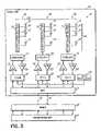
- FIG. 5is a schematic block diagram of an antenna system for use in the cellular communication system of FIG. 2 in accordance with yet another aspect of the present invention.
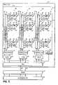
- FIG. 6Ais a schematic block diagram of a predistortion circuit in accordance with the principles of the present invention for use in the antenna system of FIG. 5 .
- FIG. 6Bis a schematic block diagram of an intermodulation generation circuit for use in the predistortion circuit of FIG. 6A .
- FIG. 7is a schematic diagram of a planar antenna array in accordance with the principles of the present invention.
- wireless communication system 30in accordance with the principles of the present invention is shown, where like numerals represent like parts to the cellular communication system 10 of FIG. 1 .
- wireless communication system 30is a digitally adaptive beamforming antenna system having multiple M ⁇ N active antenna arrays 32 supported on a tower, such as on the tower top 22 , which are oriented about the tower top 22 to provide the desired beam sectors for a defined cell. As shown in FIG.
- each active antenna array 32comprises an array of antenna elements 34 which are arranged generally in a desired pattern, such as a plurality of N vertical columns or sub-arrays 36 (designated 1 ⁇ N) with M antenna elements 34 per column (designated 1 ⁇ M).
- the M ⁇ N array 32 of antenna elements 34may be formed by suitable techniques, such as by providing strip line elements or patch elements on a suitable substrate and ground plane, for example. Of course, other configurations of the array 32 are possible as well without departing from the spirit and scope of the present invention.
- the array of antenna elements 34are operable to define multiple, individual beams for signals in one or more communication frequency bands as discussed below.
- a beammay be formed having desired shapes and directions. Beamforming with an antenna array is a known technique.
- the beam or beams formed by the active antenna array 32are digitally adaptive for a desired shape, elevation and azimuth.
- the antenna array 32is preferably driven to adaptively and selectively steer the beams as desired for the cell.
- each antenna element 34allows beam steering and in both azimuth and elevation.
- azimuth beam steeringmay be more desirable than elevation beam steering, and therefore individual signals to vertical columns or sub-arrays 36 (designated 1-N) are manipulated to achieve azimuth steering. That is, the individual columns are manipulated to provide beams which may be steered in azimuth while having a generally fixed elevation.
- a base station control unit 38 of base station 40is mounted at or near the base of the antenna tower (not shown) and is operable to transmit signals to and receive signals from each planar antenna array 32 in digital baseband.
- One or more transmission lines 42such as optical fiber cables in one embodiment, are coupled to the base station control unit 38 and each planar antenna array 32 for transmission of digital baseband signals therebetween.
- the fiber optic cables 42 of the present inventionextend up the tower and replace the large coaxial RF cables 24 of the prior art ( FIG. 1 ) and significantly reduce the expense, weight and windloading concerns presented by the prior RF cables.
- the antenna elements 34may be arranged generally in a pattern including a plurality of N vertical columns or sub-arrays 36 (designated 1-N) with M antenna elements 34 per column (designated 1-M). Each antenna element 34 of each column or sub-array 36 is coupled to an M-way power splitter 52 .
- a multicarrier linear power amplifier (LPA) 54is operatively coupled to an input of each vertical column 36 to operatively couple with the antenna elements 34 of the respective column.
- the antenna elements 34are common antenna elements that perform both transmit and receive functions.
- all antenna elements 34are configured to simultaneously transmit radio signals to the mobile stations or units 12 (referred to as “down-linking”) and receive radio signals from the mobile stations or units 12 (referred to as “up-linking”).
- a duplexer 56is operatively coupled to the input of each vertical column 36 to facilitate simultaneous transmit and receive functionality for that column array.
- the multicarrier linear power amplifiers 54are provided in the active antenna array 50 and eliminate the high amplifying power required in cellular base stations of the prior art which have large power amplifiers located at the base of the tower. By moving the transmit path amplification to the antenna arrays 50 at the tower top 22 , the significant cable losses and splitting losses associated with the passive antenna systems of the prior art are reduced.
- the multicarrier linear power amplifiers 54 of the present inventionsupport multiple carrier frequencies and provide a linearized output to the desired radiated power without violating spectral growth specifications.
- Each multicarrier linear power amplifier 54may incorporate feedforward, feedback or any other suitable linearization circuitry either as part of the multicarrier linear power amplifier 54 or remote therefrom to reduce or eliminate intermodulation distortion at the outputs of the antenna elements 34 . Incorporating multicarrier linear power amplifiers 34 at the input to each vertical column 36 mitigates signal power losses incurred getting up the tower and therefore improves antenna system efficiency over passive antenna systems of the prior art.
- a low noise amplifier (LNA) 58is operatively coupled to the output of each vertical column 36 to operatively couple with the antenna elements 34 .
- the low noise amplifiers 58are provided in the active antenna array 50 to improve receiver noise figure and sensitivity for the system.
- each planar antenna array 50incorporates a transceiver 60 operatively coupled to each vertical column or sub-array 36 .
- Each transceiver 60is operable to convert the digital baseband signals from a beamformer DSP 62 of the control unit 38 to RF signals for transmission by the antenna elements 34 during a “down-link”.
- the transceivers 60are further operable to convert RF signals received by the antenna elements 34 during an “up-link”.
- the transceivers 60are each coupled to the optical fiber transmission lines 42 through a multiplexer or MUX 64 and are driven by a suitable local oscillator (LO) 66 .
- LOlocal oscillator
- a demultiplexer or DEMUXis coupled to the beamformer DSP 62 and is further coupled to the MUX 64 through the optical fiber transmission lines 42 .
- the transceivers 60convert the down-link signals to a form which may be readily processed by various digital signal processing (DSP) techniques, such as channel digital signal processing, including time division techniques (TDMA) and code division techniques (CDMA).
- DSPdigital signal processing
- TDMAtime division techniques
- CDMAcode division techniques
- each antenna element 34is operatively coupled to an M-way power splitter 72 and to an M-way power combiner 74 .
- all antenna elements 34are configured to simultaneously transmit radio signals to the mobile stations or units 12 and receive radio signals from the mobile stations or units 12 .
- a circulator 76is operatively coupled to each antenna element 34 to facilitate simultaneous transmit and receive functionality.
- a multicarrier linear power amplifier 78is provided at or near each antenna element 34 in the transmit path with suitable filtering provided by a filter 80 at the output of each multicarrier linear power amplifier 78 .
- N ⁇ M planar antenna 70requires N ⁇ M multicarrier linear power amplifiers 78 each of which can be simple and small since the total power of each is approximately given by:
- P outis the required power output of each multicarrier linear power amplifier 78
- P totalis the total required power output of the planar antenna array 70
- N ⁇ Mis the number of multicarrier linear power amplifiers 78 incorporated in the planar antenna array 70 . Because the multicarrier linear power amplifiers 78 do not encounter cable losses up the tower or splitting losses to each antenna element 34 , the efficiency of the antenna array 70 is improved over passive antenna designs of the prior art.
- a low noise amplifier (LNA) 82is provided at or near each antenna element 34 in the receive path with suitable filtering provided by a filter 84 at the input of each low noise power amplifier 82 .
- the low noise amplifiers 82are provided in the active antenna array 70 to improve the receiver noise figure and sensitivity.
- FIG. 5illustrates a distributed active antenna array 90 in accordance with yet another aspect of the present invention and is somewhat similar in configuration to the planar antenna array 70 of FIG. 4 , where like numerals represent like elements.
- the multicarrier linear power amplifiers 78 coupled to each of the antenna elements as illustrated in FIG. 4are replaced with multicarrier power amplifiers (PA) 92 .
- Linearization of the outputs of antenna elements 34is provided by predistortion circuits 94 that are each operatively coupled to an input of a respective vertical column or sub-array 36 .
- the predistortion circuits 94are operable to reduce or eliminate generation of intermodulation distortion at the outputs of the antenna elements 34 so that a linearized output is achieved.
- the predistortion circuit 94receives the RF carrier signal from the transceivers 60 at its input 96 .
- the carrier signalis delayed by a delay circuit 100 between the input 96 and an output 102 .
- Part of the RF carrier signal energyis coupled off at the input 96 for transmission through a bottom intermodulation (IM) generation path 104 .
- An adjustable attenuator 106is provided at the input of an intermodulation (IM) generation circuit 108 to adjust the level of the coupled RF carrier signal prior to being applied to the intermodulation (IM) generation circuit 108 .
- the intermodulation (IM) generation circuit 108is illustrated in FIG. 6B and includes a 90° hybrid coupler 110 that splits the RF carrier signal into two signals that are applied to an RF carrier signal path 112 and to an intermodulation (IM) generation path 114 .
- the RF carrier signalis attenuated by fixed attenuator 116 of a sufficient value, such as a 10 dB attenuator, to ensure that no intermodulation products are generated in amplifier 120 .
- the signalis further phase adjusted by variable phase adjuster 118 .
- the attenuated and phase adjusted RF carrier signalis amplified by amplifier 120 , but do to the attenuation of the signal, the amplifier 120 does not generate any intermodulation (IM) products at its output so that the output of the amplifier 120 is the RF carrier signal without intermodulation (IM) products.
- IMintermodulation
- the RF carrier signal in the RF carrier signal path 112is attenuated by fixed attenuator 122 and applied to a second 90° hybrid coupler 124 .
- the RF carrier signalis slightly attenuated by a fixed attenuator 126 , such as a 0-1 dB attenuator, and then applied to an amplifier 128 .
- the amplifier 128has a similar or essentially the same transfer function as the transfer function of the multicarrier power amplifier 92 coupled to the antenna elements 34 and so will generate a similar or the same third, fifth and seventh order intermodulation (IM) products as the multicarrier power amplifiers 92 used in the final stage of the transmit paths.
- the amplifier 128amplifies the RF carrier signal and generates intermodulation (IM) products at its output.
- the amplified RF carrier signal and intermodulation (IM) productare then applied to a variable gain circuit 130 and a fixed attenuator 132 .
- the phase adjustment of the RF carrier signal by the variable phase adjuster 118 in the RF carrier signal path 112 , and the gain of the RF carrier signal and intermodulation (IM) products by the variable gain circuit 130 in the intermodulation (IM) generation path 114are both adjusted so that the RF carrier signal is removed at the summation of the signals at the second hybrid coupler 124 and only the intermodulation (IM) products remain in the intermodulation (IM) generation path 114 .
- the intermodulation (IM) products generated by the intermodulation (IM) generation circuit 108 of FIG. 6Bare amplified by amplifier 134 and then applied to a variable gain circuit 136 and variable phase adjuster 138 prior to summation at the output 102 .
- the RF carrier signal in the top path 98 and the intermodulation (IM) products in the intermodulation (IM) generation path 104are 180° out of phase with each other so that the summation at the output 102 comprises the RF carrier signal and the intermodulation (IM) products 180° out of phase with the RF carrier signal.
- the signal of the combined RF carrier and out of phase intermodulation (IM) productsis applied to the multicarrier power amplifiers 92 coupled to each antenna element 34 at the final stages of the transmit paths.
- the RF carrier signalis amplified and intermodulation (IM) products are generated by the amplification.
- the combined (IM) products and out of phase IM products at the output of the multicarrier power amplifiers 92provides a significant reduction/cancellation of the (IM) distortion at the amplifier outputs.
- a carrier cancellation detector 140is provided at the output of the intermodulation (IM) generation circuit 108 to monitor for the presence of the RF carrier signal at the output. If the RF carrier signal is detected, the carrier cancellation detector 140 adjusts the variable phase adjuster 118 and the variable gain circuit 130 of the intermodulation (IM) generation circuit 108 until the RF carrier signal is canceled at the output of the intermodulation (IM) generation circuit 108 .
- An intermodulation (IM) cancellation detector 142is provided at the output of each multicarrier power amplifier (PA) 92 .
- the intermodulation (IM) cancellation detector 142adjusts the variable gain circuit 136 and variable phase adjuster 138 in the bottom intermodulation (IM) generation path 104 until the intermodulation (IM) products are canceled at the outputs of the multicarrier power amplifiers 92 .
- the predistortion circuits 94suppress generation of intermodulation (IM) products by the multicarrier power amplifiers 92 so that the outputs of the antenna elements 34 are linearized.
Landscapes
- Engineering & Computer Science (AREA)
- Computer Networks & Wireless Communication (AREA)
- Variable-Direction Aerials And Aerial Arrays (AREA)
Abstract
Description
where Pout, is the required power output of each multicarrier
Claims (14)
Priority Applications (5)
| Application Number | Priority Date | Filing Date | Title |
|---|---|---|---|
| US10/260,797US7280848B2 (en) | 2002-09-30 | 2002-09-30 | Active array antenna and system for beamforming |
| DE10342746ADE10342746A1 (en) | 2002-09-30 | 2003-09-16 | Active antenna group and beam bundling system |
| GB0321886AGB2393580B (en) | 2002-09-30 | 2003-09-18 | An active array antenna and system for beamforming |
| GB0600515AGB2422961B (en) | 2002-09-30 | 2003-09-18 | An antenna base station |
| CNA031602347ACN1503587A (en) | 2002-09-30 | 2003-09-28 | Active antenna array and system for wave beam formation |
Applications Claiming Priority (1)
| Application Number | Priority Date | Filing Date | Title |
|---|---|---|---|
| US10/260,797US7280848B2 (en) | 2002-09-30 | 2002-09-30 | Active array antenna and system for beamforming |
Publications (2)
| Publication Number | Publication Date |
|---|---|
| US20040204109A1 US20040204109A1 (en) | 2004-10-14 |
| US7280848B2true US7280848B2 (en) | 2007-10-09 |
Family
ID=29270288
Family Applications (1)
| Application Number | Title | Priority Date | Filing Date |
|---|---|---|---|
| US10/260,797Expired - LifetimeUS7280848B2 (en) | 2002-09-30 | 2002-09-30 | Active array antenna and system for beamforming |
Country Status (4)
| Country | Link |
|---|---|
| US (1) | US7280848B2 (en) |
| CN (1) | CN1503587A (en) |
| DE (1) | DE10342746A1 (en) |
| GB (2) | GB2422961B (en) |
Cited By (23)
| Publication number | Priority date | Publication date | Assignee | Title |
|---|---|---|---|---|
| US20070135168A1 (en)* | 2005-12-08 | 2007-06-14 | Accton Technology Corporation | Wireless network apparatus and method of channel allocation for respective radios |
| US20070149250A1 (en)* | 2003-10-23 | 2007-06-28 | Telecom Italia S.P.A | Antenna system and method for configuring a radiating pattern |
| US20070161408A1 (en)* | 2004-09-30 | 2007-07-12 | Takahito Hashigami | Amplifier gain control method and apparatus in multi-antenna radio system |
| US20100008446A1 (en)* | 2008-07-14 | 2010-01-14 | Motorola, Inc. | Transceiver architecture with combined smart antenna calibration and digital predistortion |
| US20100297990A1 (en)* | 2008-12-12 | 2010-11-25 | Vodafone Group Plc | System and antenna for radio access networks |
| US20100311353A1 (en)* | 2009-06-08 | 2010-12-09 | Anthony Teillet | Multi-element amplitude and phase compensated antenna array with adaptive pre-distortion for wireless network |
| EP2565982A1 (en)* | 2008-02-14 | 2013-03-06 | Zinwave Limited | Communication system |
| US20130171946A1 (en)* | 2011-06-30 | 2013-07-04 | Andrew Llc | Active Antenna Sub-Array Structures |
| US8988172B1 (en)* | 2007-06-26 | 2015-03-24 | Lockheed Martin Corporation | Integrated electronic structure |
| US20160219567A1 (en)* | 2015-01-22 | 2016-07-28 | Korea Advanced Institute Of Science And Technology | Joint pattern beam sectorization method and apparatuses performing the same |
| US20160233580A1 (en)* | 2015-02-06 | 2016-08-11 | Qualcomm Incorporated | Method and apparatus to control the gain of a millimeter wave phased array system |
| US9559422B2 (en) | 2014-04-23 | 2017-01-31 | Industrial Technology Research Institute | Communication device and method for designing multi-antenna system thereof |
| US10298276B2 (en) | 2016-12-08 | 2019-05-21 | Analog Devices Global | Spatial digital pre-distortion |
| US10381736B2 (en) | 2014-02-28 | 2019-08-13 | Samsung Electronics Co., Ltd. | Method and device for extending beam area in wireless communication system |
| US20200280350A1 (en)* | 2018-02-26 | 2020-09-03 | Parallel Wireless, Inc. | Miniature Antenna Array With Polar Combining Architecture |
| US11038474B2 (en) | 2017-11-01 | 2021-06-15 | Analog Devices Global Unlimited Company | Phased array amplifier linearization |
| US11159187B2 (en)* | 2018-02-26 | 2021-10-26 | Parallel Wireless, Inc. | Microcomponent massive MIMO arrays |
| US20220271816A1 (en)* | 2018-09-10 | 2022-08-25 | Nokia Solutions And Networks Oy | Array antenna adaptive digital pre-distortion with bayesian observation analysis |
| US11528068B2 (en) | 2018-07-30 | 2022-12-13 | Innophase, Inc. | System and method for massive MIMO communication |
| US11532897B2 (en) | 2018-11-01 | 2022-12-20 | Innophase, Inc. | Reconfigurable phase array |
| US20230090153A1 (en)* | 2021-09-20 | 2023-03-23 | Yanik Freeman | Wireless Fire Rate of Growth (FROG) system |
| US11750261B2 (en) | 2021-10-14 | 2023-09-05 | Industrial Technology Research Institute | Analog beamformer used for array antenna and operating method thereof |
| US12244066B2 (en) | 2019-10-28 | 2025-03-04 | Innophase, Inc. | Multi-band massive MIMO antenna array |
Families Citing this family (92)
| Publication number | Priority date | Publication date | Assignee | Title |
|---|---|---|---|---|
| US20040198453A1 (en)* | 2002-09-20 | 2004-10-07 | David Cutrer | Distributed wireless network employing utility poles and optical signal distribution |
| US7339979B1 (en)* | 2003-02-11 | 2008-03-04 | Calamp Corp. | Adaptive beamforming methods and systems that enhance performance and reduce computations |
| FI20030663A0 (en)* | 2003-05-02 | 2003-05-02 | Nokia Corp | Antenna arrangement and base station |
| WO2005053182A1 (en)* | 2003-11-25 | 2005-06-09 | Zte Corporation | A method and apparatu for implementing beam forming in cdma communication system |
| US7495560B2 (en)* | 2006-05-08 | 2009-02-24 | Corning Cable Systems Llc | Wireless picocellular RFID systems and methods |
| US8472767B2 (en)* | 2006-05-19 | 2013-06-25 | Corning Cable Systems Llc | Fiber optic cable and fiber optic cable assembly for wireless access |
| US20070292136A1 (en)* | 2006-06-16 | 2007-12-20 | Michael Sauer | Transponder for a radio-over-fiber optical fiber cable |
| US7962174B2 (en)* | 2006-07-12 | 2011-06-14 | Andrew Llc | Transceiver architecture and method for wireless base-stations |
| GB2440192B (en)* | 2006-07-17 | 2011-05-04 | Ubidyne Inc | Antenna array system |
| EP1885024A1 (en)* | 2006-08-03 | 2008-02-06 | Selex Sensors and Airborne Systems Limited | Antenna |
| US7627250B2 (en) | 2006-08-16 | 2009-12-01 | Corning Cable Systems Llc | Radio-over-fiber transponder with a dual-band patch antenna system |
| US7787823B2 (en) | 2006-09-15 | 2010-08-31 | Corning Cable Systems Llc | Radio-over-fiber (RoF) optical fiber cable system with transponder diversity and RoF wireless picocellular system using same |
| US7848654B2 (en) | 2006-09-28 | 2010-12-07 | Corning Cable Systems Llc | Radio-over-fiber (RoF) wireless picocellular system with combined picocells |
| US8873585B2 (en) | 2006-12-19 | 2014-10-28 | Corning Optical Communications Wireless Ltd | Distributed antenna system for MIMO technologies |
| US8111998B2 (en) | 2007-02-06 | 2012-02-07 | Corning Cable Systems Llc | Transponder systems and methods for radio-over-fiber (RoF) wireless picocellular systems |
| KR101013065B1 (en)* | 2007-04-27 | 2011-02-14 | 삼성전자주식회사 | Apparatus and method for performing low power amplification in wireless communication system |
| US20100054746A1 (en) | 2007-07-24 | 2010-03-04 | Eric Raymond Logan | Multi-port accumulator for radio-over-fiber (RoF) wireless picocellular systems |
| US8175459B2 (en) | 2007-10-12 | 2012-05-08 | Corning Cable Systems Llc | Hybrid wireless/wired RoF transponder and hybrid RoF communication system using same |
| US8644844B2 (en) | 2007-12-20 | 2014-02-04 | Corning Mobileaccess Ltd. | Extending outdoor location based services and applications into enclosed areas |
| US20090233644A1 (en)* | 2008-03-11 | 2009-09-17 | Matsushita Electric Industrial Co., Ltd. | Multiple carrier radio systems and methods employing polar active antenna elements |
| CN101651480B (en)* | 2008-08-14 | 2013-04-24 | 华为技术有限公司 | Active antenna, base station, method for updating amplitude and phase, and signal processing method |
| US20100087227A1 (en)* | 2008-10-02 | 2010-04-08 | Alvarion Ltd. | Wireless base station design |
| CN102369678B (en) | 2009-02-03 | 2015-08-19 | 康宁光缆系统有限责任公司 | Optical fiber based distributed antenna systems, assemblies and related methods for calibrating optical fiber based distributed antenna systems, assemblies |
| CN102396171B (en) | 2009-02-03 | 2015-09-30 | 康宁光缆系统有限责任公司 | Based on the distributing antenna system of optical fiber, assembly and the correlation technique for monitoring and configure distributing antenna system based on optical fiber, assembly |
| US9673904B2 (en) | 2009-02-03 | 2017-06-06 | Corning Optical Communications LLC | Optical fiber-based distributed antenna systems, components, and related methods for calibration thereof |
| US7876263B2 (en)* | 2009-02-24 | 2011-01-25 | Raytheon Company | Asymmetrically thinned active array TR module and antenna architecture |
| WO2010135862A1 (en) | 2009-05-26 | 2010-12-02 | 华为技术有限公司 | Antenna device |
| US8548330B2 (en) | 2009-07-31 | 2013-10-01 | Corning Cable Systems Llc | Sectorization in distributed antenna systems, and related components and methods |
| US8280259B2 (en) | 2009-11-13 | 2012-10-02 | Corning Cable Systems Llc | Radio-over-fiber (RoF) system for protocol-independent wired and/or wireless communication |
| CN101777694B (en)* | 2009-11-16 | 2012-10-03 | 福建省泉州华鸿通讯有限公司 | Novel interphone large-power active antenna |
| US9030363B2 (en)* | 2009-12-29 | 2015-05-12 | Kathrein-Werke Ag | Method and apparatus for tilting beams in a mobile communications network |
| US8433242B2 (en)* | 2009-12-29 | 2013-04-30 | Ubidyne Inc. | Active antenna array for a mobile communications network with multiple amplifiers using separate polarisations for transmission and a combination of polarisations for reception of separate protocol signals |
| US8731616B2 (en)* | 2009-12-29 | 2014-05-20 | Kathrein -Werke KG | Active antenna array and method for relaying first and second protocol radio signals in a mobile communications network |
| US8423028B2 (en)* | 2009-12-29 | 2013-04-16 | Ubidyne, Inc. | Active antenna array with multiple amplifiers for a mobile communications network and method of providing DC voltage to at least one processing element |
| US8275265B2 (en) | 2010-02-15 | 2012-09-25 | Corning Cable Systems Llc | Dynamic cell bonding (DCB) for radio-over-fiber (RoF)-based networks and communication systems and related methods |
| CN102948017B (en)* | 2010-04-23 | 2016-07-06 | 英派尔科技开发有限公司 | The active electrical with distributed amplifier adjusts inclined antenna equipment |
| US20110268446A1 (en) | 2010-05-02 | 2011-11-03 | Cune William P | Providing digital data services in optical fiber-based distributed radio frequency (rf) communications systems, and related components and methods |
| US9525488B2 (en) | 2010-05-02 | 2016-12-20 | Corning Optical Communications LLC | Digital data services and/or power distribution in optical fiber-based distributed communications systems providing digital data and radio frequency (RF) communications services, and related components and methods |
| WO2012024247A1 (en) | 2010-08-16 | 2012-02-23 | Corning Cable Systems Llc | Remote antenna clusters and related systems, components, and methods supporting digital data signal propagation between remote antenna units |
| US9252874B2 (en) | 2010-10-13 | 2016-02-02 | Ccs Technology, Inc | Power management for remote antenna units in distributed antenna systems |
| US20120128040A1 (en) | 2010-11-23 | 2012-05-24 | Peter Kenington | Module for an Active Antenna System |
| US20120196545A1 (en)* | 2011-01-28 | 2012-08-02 | Georg Schmidt | Antenna array and method for synthesizing antenna patterns |
| EP2487800B1 (en) | 2011-02-11 | 2013-06-19 | Alcatel Lucent | Active antenna arrays |
| EP2678972B1 (en) | 2011-02-21 | 2018-09-05 | Corning Optical Communications LLC | Providing digital data services as electrical signals and radio-frequency (rf) communications over optical fiber in distributed communications systems, and related components and methods |
| US10475754B2 (en)* | 2011-03-02 | 2019-11-12 | Nokomis, Inc. | System and method for physically detecting counterfeit electronics |
| WO2012148938A1 (en) | 2011-04-29 | 2012-11-01 | Corning Cable Systems Llc | Determining propagation delay of communications in distributed antenna systems, and related components, systems and methods |
| WO2012148940A1 (en) | 2011-04-29 | 2012-11-01 | Corning Cable Systems Llc | Systems, methods, and devices for increasing radio frequency (rf) power in distributed antenna systems |
| EP2713527B1 (en)* | 2011-05-25 | 2018-01-03 | Huawei Technologies Co., Ltd. | Base station device and signal transmission method thereof |
| US9621330B2 (en)* | 2011-11-30 | 2017-04-11 | Maxlinear Asia Singapore Private Limited | Split microwave backhaul transceiver architecture with coaxial interconnect |
| EP2814115B1 (en)* | 2012-03-20 | 2023-04-19 | Huawei Technologies Co., Ltd. | Antenna system, base station system and communication system |
| EP2832012A1 (en) | 2012-03-30 | 2015-02-04 | Corning Optical Communications LLC | Reducing location-dependent interference in distributed antenna systems operating in multiple-input, multiple-output (mimo) configuration, and related components, systems, and methods |
| WO2013162988A1 (en) | 2012-04-25 | 2013-10-31 | Corning Cable Systems Llc | Distributed antenna system architectures |
| WO2014024192A1 (en) | 2012-08-07 | 2014-02-13 | Corning Mobile Access Ltd. | Distribution of time-division multiplexed (tdm) management services in a distributed antenna system, and related components, systems, and methods |
| US9455784B2 (en) | 2012-10-31 | 2016-09-27 | Corning Optical Communications Wireless Ltd | Deployable wireless infrastructures and methods of deploying wireless infrastructures |
| US9094254B2 (en) | 2012-11-15 | 2015-07-28 | Telefonaktiebolaget L M Ericsson (Publ) | Method and apparatus for antenna array calibration using traffic signals |
| US9025575B2 (en)* | 2012-11-15 | 2015-05-05 | Telefonaktiebolaget Lm Ericsson (Publ) | Antenna array calibration using traffic signals |
| CN105308876B (en) | 2012-11-29 | 2018-06-22 | 康宁光电通信有限责任公司 | Remote unit antennas in distributing antenna system combines |
| US9647758B2 (en) | 2012-11-30 | 2017-05-09 | Corning Optical Communications Wireless Ltd | Cabling connectivity monitoring and verification |
| CN103916153B (en)* | 2013-01-04 | 2016-03-02 | 中国移动通信集团公司 | A kind of micro-station of active integrated antenna |
| US9042323B1 (en) | 2013-01-18 | 2015-05-26 | Sprint Spectrum L.P. | Method and system of activating a global beam in a coverage area |
| WO2014199380A1 (en) | 2013-06-12 | 2014-12-18 | Corning Optical Communications Wireless, Ltd. | Time-division duplexing (tdd) in distributed communications systems, including distributed antenna systems (dass) |
| CN105452951B (en) | 2013-06-12 | 2018-10-19 | 康宁光电通信无线公司 | Voltage type optical directional coupler |
| US9247543B2 (en) | 2013-07-23 | 2016-01-26 | Corning Optical Communications Wireless Ltd | Monitoring non-supported wireless spectrum within coverage areas of distributed antenna systems (DASs) |
| US9661781B2 (en) | 2013-07-31 | 2017-05-23 | Corning Optical Communications Wireless Ltd | Remote units for distributed communication systems and related installation methods and apparatuses |
| US9385810B2 (en) | 2013-09-30 | 2016-07-05 | Corning Optical Communications Wireless Ltd | Connection mapping in distributed communication systems |
| US9178635B2 (en) | 2014-01-03 | 2015-11-03 | Corning Optical Communications Wireless Ltd | Separation of communication signal sub-bands in distributed antenna systems (DASs) to reduce interference |
| KR101736876B1 (en) | 2014-01-06 | 2017-05-17 | 삼성전자주식회사 | Method and apparatus for transceiving for beam forming in wireless communication system |
| US9775123B2 (en) | 2014-03-28 | 2017-09-26 | Corning Optical Communications Wireless Ltd. | Individualized gain control of uplink paths in remote units in a distributed antenna system (DAS) based on individual remote unit contribution to combined uplink power |
| US9357551B2 (en) | 2014-05-30 | 2016-05-31 | Corning Optical Communications Wireless Ltd | Systems and methods for simultaneous sampling of serial digital data streams from multiple analog-to-digital converters (ADCS), including in distributed antenna systems |
| US10224642B2 (en)* | 2014-06-03 | 2019-03-05 | Airrays Gmbh | Modular antenna system |
| US9525472B2 (en) | 2014-07-30 | 2016-12-20 | Corning Incorporated | Reducing location-dependent destructive interference in distributed antenna systems (DASS) operating in multiple-input, multiple-output (MIMO) configuration, and related components, systems, and methods |
| US9730228B2 (en) | 2014-08-29 | 2017-08-08 | Corning Optical Communications Wireless Ltd | Individualized gain control of remote uplink band paths in a remote unit in a distributed antenna system (DAS), based on combined uplink power level in the remote unit |
| US9602210B2 (en) | 2014-09-24 | 2017-03-21 | Corning Optical Communications Wireless Ltd | Flexible head-end chassis supporting automatic identification and interconnection of radio interface modules and optical interface modules in an optical fiber-based distributed antenna system (DAS) |
| US9420542B2 (en) | 2014-09-25 | 2016-08-16 | Corning Optical Communications Wireless Ltd | System-wide uplink band gain control in a distributed antenna system (DAS), based on per band gain control of remote uplink paths in remote units |
| US10659163B2 (en) | 2014-09-25 | 2020-05-19 | Corning Optical Communications LLC | Supporting analog remote antenna units (RAUs) in digital distributed antenna systems (DASs) using analog RAU digital adaptors |
| WO2016071902A1 (en) | 2014-11-03 | 2016-05-12 | Corning Optical Communications Wireless Ltd. | Multi-band monopole planar antennas configured to facilitate improved radio frequency (rf) isolation in multiple-input multiple-output (mimo) antenna arrangement |
| WO2016075696A1 (en) | 2014-11-13 | 2016-05-19 | Corning Optical Communications Wireless Ltd. | Analog distributed antenna systems (dass) supporting distribution of digital communications signals interfaced from a digital signal source and analog radio frequency (rf) communications signals |
| US9729267B2 (en) | 2014-12-11 | 2017-08-08 | Corning Optical Communications Wireless Ltd | Multiplexing two separate optical links with the same wavelength using asymmetric combining and splitting |
| WO2016098109A1 (en) | 2014-12-18 | 2016-06-23 | Corning Optical Communications Wireless Ltd. | Digital interface modules (dims) for flexibly distributing digital and/or analog communications signals in wide-area analog distributed antenna systems (dass) |
| WO2016098111A1 (en) | 2014-12-18 | 2016-06-23 | Corning Optical Communications Wireless Ltd. | Digital- analog interface modules (da!ms) for flexibly.distributing digital and/or analog communications signals in wide-area analog distributed antenna systems (dass) |
| US20160249365A1 (en) | 2015-02-19 | 2016-08-25 | Corning Optical Communications Wireless Ltd. | Offsetting unwanted downlink interference signals in an uplink path in a distributed antenna system (das) |
| US9681313B2 (en) | 2015-04-15 | 2017-06-13 | Corning Optical Communications Wireless Ltd | Optimizing remote antenna unit performance using an alternative data channel |
| US9948349B2 (en) | 2015-07-17 | 2018-04-17 | Corning Optical Communications Wireless Ltd | IOT automation and data collection system |
| US10560214B2 (en) | 2015-09-28 | 2020-02-11 | Corning Optical Communications LLC | Downlink and uplink communication path switching in a time-division duplex (TDD) distributed antenna system (DAS) |
| EP3381129B1 (en)* | 2015-11-27 | 2020-08-05 | Telefonaktiebolaget LM Ericsson (publ) | Linearization of active antenna array |
| US10236924B2 (en) | 2016-03-31 | 2019-03-19 | Corning Optical Communications Wireless Ltd | Reducing out-of-channel noise in a wireless distribution system (WDS) |
| US10715261B2 (en) | 2016-05-24 | 2020-07-14 | Telefonaktiebolaget Lm Ericsson (Publ) | Method and apparatus for antenna array calibration using on-board receiver |
| CN110168953A (en)* | 2017-01-12 | 2019-08-23 | 瑞典爱立信有限公司 | Dual polarization beam forming |
| JP7074772B2 (en)* | 2017-05-15 | 2022-05-24 | コムスコープ テクノロジーズ リミティド ライアビリティ カンパニー | Phased array antennas with switched elevation beam widths and related methods |
| CA3068079C (en) | 2017-06-26 | 2022-11-29 | Huawei Technologies Co., Ltd. | Correction apparatus and correction method |
| US10972193B2 (en) | 2017-09-06 | 2021-04-06 | Telefonaktiebolaget Lm Ericsson (Publ) | Method and apparatus for antenna array calibration with interference reduction |
| EP3704820B1 (en) | 2017-10-31 | 2022-04-27 | Telefonaktiebolaget LM Ericsson (publ) | Orthogonal training signals for transmission in an antenna array |
Citations (141)
| Publication number | Priority date | Publication date | Assignee | Title |
|---|---|---|---|---|
| US4070637A (en) | 1976-03-25 | 1978-01-24 | Communications Satellite Corporation | Redundant microwave configuration |
| US4124852A (en) | 1977-01-24 | 1978-11-07 | Raytheon Company | Phased power switching system for scanning antenna array |
| US4246585A (en) | 1979-09-07 | 1981-01-20 | The United States Of America As Represented By The Secretary Of The Air Force | Subarray pattern control and null steering for subarray antenna systems |
| US4360813A (en) | 1980-03-19 | 1982-11-23 | The Boeing Company | Power combining antenna structure |
| US4566013A (en) | 1983-04-01 | 1986-01-21 | The United States Of America As Represented By The Secretary Of The Navy | Coupled amplifier module feed networks for phased array antennas |
| US4607389A (en) | 1984-02-03 | 1986-08-19 | Amoco Corporation | Communication system for transmitting an electrical signal |
| US4614947A (en) | 1983-04-22 | 1986-09-30 | U.S. Philips Corporation | Planar high-frequency antenna having a network of fully suspended-substrate microstrip transmission lines |
| US4689631A (en) | 1985-05-28 | 1987-08-25 | American Telephone And Telegraph Company, At&T Bell Laboratories | Space amplifier |
| EP0245955A2 (en) | 1986-05-16 | 1987-11-19 | GEC-Marconi Limited | Amplifying circuit arrangement |
| US4825172A (en) | 1987-03-30 | 1989-04-25 | Hughes Aircraft Company | Equal power amplifier system for active phase array antenna and method of arranging same |
| US4849763A (en) | 1987-04-23 | 1989-07-18 | Hughes Aircraft Company | Low sidelobe phased array antenna using identical solid state modules |
| US4890110A (en) | 1988-01-12 | 1989-12-26 | Nec Corporation | Microwave landing system |
| US4994813A (en) | 1988-10-13 | 1991-02-19 | Mitsubishi Denki Kabushiki Denki | Antenna system |
| US5034752A (en) | 1989-07-04 | 1991-07-23 | Thomson Csf | Multiple-beam antenna system with active modules and digital beam-forming |
| US5038150A (en) | 1990-05-14 | 1991-08-06 | Hughes Aircraft Company | Feed network for a dual circular and dual linear polarization antenna |
| US5061939A (en) | 1989-05-23 | 1991-10-29 | Harada Kogyo Kabushiki Kaisha | Flat-plate antenna for use in mobile communications |
| US5206604A (en) | 1991-12-20 | 1993-04-27 | Harris Corporation | Broadband high power amplifier |
| US5230080A (en) | 1990-03-09 | 1993-07-20 | Compagnie Generale Des Matieres Nucleaires | Ultra-high frequency communication installation |
| EP0551556A1 (en) | 1992-01-15 | 1993-07-21 | Communications Satellite Corporation | Low loss, broadband stripline-to-microstrip transition |
| US5247310A (en) | 1992-06-24 | 1993-09-21 | The United States Of America As Represented By The Secretary Of The Navy | Layered parallel interface for an active antenna array |
| US5248980A (en) | 1991-04-05 | 1993-09-28 | Alcatel Espace | Spacecraft payload architecture |
| US5270721A (en) | 1989-05-15 | 1993-12-14 | Matsushita Electric Works, Ltd. | Planar antenna |
| US5280297A (en) | 1992-04-06 | 1994-01-18 | General Electric Co. | Active reflectarray antenna for communication satellite frequency re-use |
| US5327150A (en) | 1993-03-03 | 1994-07-05 | Hughes Aircraft Company | Phased array antenna for efficient radiation of microwave and thermal energy |
| US5355143A (en) | 1991-03-06 | 1994-10-11 | Huber & Suhner Ag, Kabel-, Kautschuk-, Kunststoffwerke | Enhanced performance aperture-coupled planar antenna array |
| USRE34796E (en) | 1989-09-05 | 1994-11-22 | Motorola, Inc. | Antenna switching system |
| US5379455A (en) | 1991-02-28 | 1995-01-03 | Hewlett-Packard Company | Modular distributed antenna system |
| EP0639035A1 (en) | 1993-08-12 | 1995-02-15 | Nortel Networks Corporation | Base station antenna arrangement |
| US5412414A (en) | 1988-04-08 | 1995-05-02 | Martin Marietta Corporation | Self monitoring/calibrating phased array radar and an interchangeable, adjustable transmit/receive sub-assembly |
| US5437052A (en) | 1993-04-16 | 1995-07-25 | Conifer Corporation | MMDS over-the-air bi-directional TV/data transmission system and method therefor |
| GB2286749A (en) | 1994-02-16 | 1995-08-23 | Northern Telecom Ltd | Base station antenna arrangement |
| WO1995026116A1 (en) | 1994-03-24 | 1995-09-28 | Ericsson Inc. | Phased array cellular base station and associated methods for enhanced power efficiency |
| US5457557A (en) | 1994-01-21 | 1995-10-10 | Ortel Corporation | Low cost optical fiber RF signal distribution system |
| WO1995034102A1 (en) | 1994-06-03 | 1995-12-14 | Telefonaktiebolaget Lm Ericsson | Microstrip antenna array |
| JPH08102618A (en) | 1994-09-30 | 1996-04-16 | Toshiba Corp | Multi-beam antenna |
| US5513176A (en) | 1990-12-07 | 1996-04-30 | Qualcomm Incorporated | Dual distributed antenna system |
| EP0447218B1 (en) | 1990-03-15 | 1996-05-08 | Hughes Aircraft Company | Plural frequency patch antenna assembly |
| EP0713261A1 (en) | 1994-11-18 | 1996-05-22 | Hughes Aircraft Company | Phased array antenna management system and calibration method |
| US5554865A (en) | 1995-06-07 | 1996-09-10 | Hughes Aircraft Company | Integrated transmit/receive switch/low noise amplifier with dissimilar semiconductor devices |
| US5568160A (en) | 1990-06-14 | 1996-10-22 | Collins; John L. F. C. | Planar horn array microwave antenna |
| US5604462A (en) | 1995-11-17 | 1997-02-18 | Lucent Technologies Inc. | Intermodulation distortion detection in a power shared amplifier network |
| US5604925A (en) | 1995-04-28 | 1997-02-18 | Raytheon E-Systems | Super low noise multicoupler |
| US5610510A (en) | 1994-06-30 | 1997-03-11 | The Johns Hopkins University | High-temperature superconducting thin film nonbolometric microwave detection system and method |
| US5619210A (en) | 1994-04-08 | 1997-04-08 | Ericsson Inc. | Large phased-array communications satellite |
| US5623269A (en) | 1993-05-07 | 1997-04-22 | Space Systems/Loral, Inc. | Mobile communication satellite payload |
| US5644622A (en) | 1992-09-17 | 1997-07-01 | Adc Telecommunications, Inc. | Cellular communications system with centralized base stations and distributed antenna units |
| US5644316A (en) | 1996-05-02 | 1997-07-01 | Hughes Electronics | Active phased array adjustment using transmit amplitude adjustment range measurements |
| US5646631A (en) | 1995-12-15 | 1997-07-08 | Lucent Technologies Inc. | Peak power reduction in power sharing amplifier networks |
| US5659322A (en) | 1992-12-04 | 1997-08-19 | Alcatel N.V. | Variable synthesized polarization active antenna |
| US5680142A (en) | 1995-11-07 | 1997-10-21 | Smith; David Anthony | Communication system and method utilizing an antenna having adaptive characteristics |
| WO1997044914A1 (en) | 1996-05-20 | 1997-11-27 | Scientific Research Corporation | Pcs cell site system for allowing a plurality of pcs providers to share cell site antennas |
| US5710804A (en) | 1995-07-19 | 1998-01-20 | Pcs Solutions, Llc | Service protection enclosure for and method of constructing a remote wireless telecommunication site |
| US5714957A (en) | 1993-08-12 | 1998-02-03 | Northern Telecom Limited | Base station antenna arrangement |
| US5724666A (en) | 1994-03-24 | 1998-03-03 | Ericsson Inc. | Polarization diversity phased array cellular base station and associated methods |
| WO1998009372A1 (en) | 1996-08-27 | 1998-03-05 | Telefonaktiebolaget Lm Ericsson (Publ) | Method of and apparatus for filtering intermodulation products in a radiocommunication system |
| WO1998011626A1 (en) | 1996-09-16 | 1998-03-19 | Raytheon Company | Antenna system for enhancing the coverage area, range and reliability of wireless base stations |
| US5745841A (en) | 1996-05-20 | 1998-04-28 | Metawave Communications Corporation | System and method for cellular beam spectrum management |
| US5751250A (en) | 1995-10-13 | 1998-05-12 | Lucent Technologies, Inc. | Low distortion power sharing amplifier network |
| US5754139A (en) | 1996-10-30 | 1998-05-19 | Motorola, Inc. | Method and intelligent digital beam forming system responsive to traffic demand |
| US5758287A (en) | 1994-05-20 | 1998-05-26 | Airtouch Communications, Inc. | Hub and remote cellular telephone system |
| US5770970A (en) | 1995-08-30 | 1998-06-23 | Matsushita Electric Industrial Co., Ltd. | Transmitter of wireless system and high frequency power amplifier used therein |
| US5771017A (en) | 1993-08-12 | 1998-06-23 | Northern Telecom Limited | Base station antenna arrangement |
| GB2320618A (en) | 1996-12-20 | 1998-06-24 | Northern Telecom Ltd | Base station antenna arrangement with narrow overlapping beams |
| US5774666A (en) | 1996-10-18 | 1998-06-30 | Silicon Graphics, Inc. | System and method for displaying uniform network resource locators embedded in time-based medium |
| US5784031A (en) | 1997-02-28 | 1998-07-21 | Wireless Online, Inc. | Versatile anttenna array for multiple pencil beams and efficient beam combinations |
| US5790078A (en) | 1993-10-22 | 1998-08-04 | Nec Corporation | Superconducting mixer antenna array |
| US5802173A (en) | 1991-01-15 | 1998-09-01 | Rogers Cable Systems Limited | Radiotelephony system |
| WO1998039851A1 (en) | 1997-03-03 | 1998-09-11 | Celletra Ltd. | Cellular communications systems |
| US5809395A (en) | 1991-01-15 | 1998-09-15 | Rogers Cable Systems Limited | Remote antenna driver for a radio telephony system |
| US5815115A (en) | 1995-12-26 | 1998-09-29 | Lucent Technologies Inc. | High speed wireless transmitters and receivers |
| US5825762A (en) | 1996-09-24 | 1998-10-20 | Motorola, Inc. | Apparatus and methods for providing wireless communication to a sectorized coverage area |
| US5832389A (en) | 1994-03-24 | 1998-11-03 | Ericsson Inc. | Wideband digitization systems and methods for cellular radiotelephones |
| US5835128A (en) | 1996-11-27 | 1998-11-10 | Hughes Electronics Corporation | Wireless redistribution of television signals in a multiple dwelling unit |
| WO1998050981A1 (en) | 1997-05-07 | 1998-11-12 | Telefonaktiebolaget Lm Ericsson (Publ) | Radio antenna system |
| EP0878974A1 (en) | 1997-05-16 | 1998-11-18 | Italtel s.p.a. | Communication method and a base transceiver station for a mobile radio communication system |
| US5854611A (en) | 1995-07-24 | 1998-12-29 | Lucent Technologies Inc. | Power shared linear amplifier network |
| US5856804A (en) | 1996-10-30 | 1999-01-05 | Motorola, Inc. | Method and intelligent digital beam forming system with improved signal quality communications |
| US5872547A (en) | 1996-07-16 | 1999-02-16 | Metawave Communications Corporation | Conical omni-directional coverage multibeam antenna with parasitic elements |
| US5878345A (en) | 1992-03-06 | 1999-03-02 | Aircell, Incorporated | Antenna for nonterrestrial mobile telecommunication system |
| US5880701A (en) | 1996-06-25 | 1999-03-09 | Pcs Solutions, Llc | Enclosed wireless telecommunications antenna |
| US5884147A (en) | 1996-01-03 | 1999-03-16 | Metawave Communications Corporation | Method and apparatus for improved control over cellular systems |
| US5889494A (en) | 1997-01-27 | 1999-03-30 | Metawave Communications Corporation | Antenna deployment sector cell shaping system and method |
| US5896104A (en) | 1991-09-04 | 1999-04-20 | Honda Giken Kogyo Kabushiki Kaisha | FM radar system |
| WO1999026317A1 (en) | 1997-11-14 | 1999-05-27 | Radio Design Innovation Tj Ab | An antenna system with a feeder cable |
| US5929823A (en) | 1997-07-17 | 1999-07-27 | Metawave Communications Corporation | Multiple beam planar array with parasitic elements |
| US5933113A (en) | 1996-09-05 | 1999-08-03 | Raytheon Company | Simultaneous multibeam and frequency active photonic array radar apparatus |
| US5936577A (en) | 1996-10-18 | 1999-08-10 | Kabushiki Kaisha Toshiba | Adaptive antenna |
| US5936591A (en) | 1996-04-11 | 1999-08-10 | Advanced Space Communications Research Laboratory (Asc) | Multi-beam feeding apparatus |
| US5940045A (en) | 1996-12-30 | 1999-08-17 | Harris Corporation | Optimization of DC power to effective irradiated power conversion efficiency for helical antenna |
| US5949376A (en) | 1997-07-29 | 1999-09-07 | Alcatel Alsthom Compagnie Generale D'electricite | Dual polarization patch antenna |
| US5969689A (en) | 1997-01-13 | 1999-10-19 | Metawave Communications Corporation | Multi-sector pivotal antenna system and method |
| US5987335A (en) | 1997-09-24 | 1999-11-16 | Lucent Technologies Inc. | Communication system comprising lightning protection |
| JPH11330838A (en) | 1998-05-08 | 1999-11-30 | Mitsubishi Electric Corp | Active array antenna device |
| US6008763A (en) | 1996-05-13 | 1999-12-28 | Allgon Ab | Flat antenna |
| WO2000003479A1 (en) | 1998-07-10 | 2000-01-20 | Telefonaktiebolaget Lm Ericsson (Publ) | Arrangement and method relating to radio communication |
| US6018643A (en) | 1997-06-03 | 2000-01-25 | Texas Instruments Incorporated | Apparatus and method for adaptively forming an antenna beam pattern in a wireless communication system |
| US6020848A (en) | 1998-01-27 | 2000-02-01 | The Boeing Company | Monolithic microwave integrated circuits for use in low-cost dual polarization phased-array antennas |
| EP0984554A2 (en) | 1998-08-31 | 2000-03-08 | Lucent Technologies Inc. | Feed forward amplifier improvement incorporating an automatic gain and phase controller |
| US6038459A (en) | 1992-10-19 | 2000-03-14 | Nortel Networks Corporation | Base station antenna arrangement |
| US6037903A (en) | 1998-08-05 | 2000-03-14 | California Amplifier, Inc. | Slot-coupled array antenna structures |
| US6043790A (en) | 1997-03-24 | 2000-03-28 | Telefonaktiebolaget Lm Ericsson | Integrated transmit/receive antenna with arbitrary utilization of the antenna aperture |
| US6047199A (en) | 1997-08-15 | 2000-04-04 | Bellsouth Intellectual Property Corporation | Systems and methods for transmitting mobile radio signals |
| EP0994567A2 (en) | 1998-10-15 | 2000-04-19 | Lucent Technologies Inc. | Orthogonally polarized transmission antenna and method of transmission |
| US6055230A (en) | 1997-09-05 | 2000-04-25 | Metawave Communications Corporation | Embedded digital beam switching |
| US6070090A (en) | 1997-11-13 | 2000-05-30 | Metawave Communications Corporation | Input specific independent sector mapping |
| WO2000031824A1 (en) | 1998-11-20 | 2000-06-02 | Telefonaktiebolaget Lm Ericsson | Improvement of polarization isolation in antennas |
| US6072434A (en) | 1997-02-04 | 2000-06-06 | Lucent Technologies Inc. | Aperture-coupled planar inverted-F antenna |
| WO2000039943A1 (en) | 1998-12-23 | 2000-07-06 | Telefonaktiebolaget Lm Ericsson (Publ) | Multi-transmitter system |
| US6091360A (en) | 1997-08-20 | 2000-07-18 | Hollandse Signaalapparaten B.V. | Antenna system |
| US6094165A (en) | 1997-07-31 | 2000-07-25 | Nortel Networks Corporation | Combined multi-beam and sector coverage antenna array |
| US6104935A (en) | 1997-05-05 | 2000-08-15 | Nortel Networks Corporation | Down link beam forming architecture for heavily overlapped beam configuration |
| US6140976A (en) | 1999-09-07 | 2000-10-31 | Motorola, Inc. | Method and apparatus for mitigating array antenna performance degradation caused by element failure |
| US6144652A (en) | 1996-11-08 | 2000-11-07 | Lucent Technologies Inc. | TDM-based fixed wireless loop system |
| US6157343A (en) | 1996-09-09 | 2000-12-05 | Telefonaktiebolaget Lm Ericsson | Antenna array calibration |
| US6160514A (en) | 1999-10-15 | 2000-12-12 | Andrew Corporation | L-shaped indoor antenna |
| WO2001006801A1 (en)* | 1999-07-21 | 2001-01-25 | Celletra, Ltd. | Scalable cellular communications system |
| US6181276B1 (en) | 1998-10-09 | 2001-01-30 | Metawave Communications Corporation | Sector shaping transition system and method |
| US6188373B1 (en) | 1996-07-16 | 2001-02-13 | Metawave Communications Corporation | System and method for per beam elevation scanning |
| US6195556B1 (en) | 1997-07-15 | 2001-02-27 | Metawave Communications Corporation | System and method of determining a mobile station's position using directable beams |
| US6198460B1 (en) | 1998-02-12 | 2001-03-06 | Sony International (Europe) Gmbh | Antenna support structure |
| US6198434B1 (en) | 1998-12-17 | 2001-03-06 | Metawave Communications Corporation | Dual mode switched beam antenna |
| US6198435B1 (en) | 1997-01-27 | 2001-03-06 | Metawave Communications Corporation | System and method for improved trunking efficiency through sector overlap |
| US6201801B1 (en) | 1994-03-24 | 2001-03-13 | Ericsson Inc. | Polarization diversity phased array cellular base station and associated methods |
| US6222503B1 (en) | 1997-01-10 | 2001-04-24 | William Gietema | System and method of integrating and concealing antennas, antenna subsystems and communications subsystems |
| US6233466B1 (en) | 1998-12-14 | 2001-05-15 | Metawave Communications Corporation | Downlink beamforming using beam sweeping and subscriber feedback |
| US6233434B1 (en) | 1998-08-28 | 2001-05-15 | Hitachi, Ltd. | System for transmitting/receiving a signal having a carrier frequency band for a radio base station |
| US6240274B1 (en) | 1999-04-21 | 2001-05-29 | Hrl Laboratories, Llc | High-speed broadband wireless communication system architecture |
| US6246674B1 (en) | 1997-01-27 | 2001-06-12 | Metawave Communications Corporation | Antenna deployment sector cell shaping system and method |
| EP1111821A2 (en) | 1999-12-21 | 2001-06-27 | Lucent Technologies Inc. | Wireless system combining arrangment and method thereof |
| US6266545B1 (en) | 1998-10-21 | 2001-07-24 | Telefonaktiebolaget Lm Ericsson (Publ) | Transferring data in a fixed-site radio transceiver station by modulating power supply current |
| US6269255B1 (en) | 1997-10-21 | 2001-07-31 | Interwave Communications International, Ltd. | Self-contained masthead units for cellular communication networks |
| US20020008577A1 (en) | 2000-05-19 | 2002-01-24 | Spectrian Corporation | High linearity multicarrier RF amplifier |
| WO2002019470A1 (en)* | 2000-09-02 | 2002-03-07 | Nokia Corporation | Fixed beam antenna array, base station and method for transmitting signals via a fixed beam antenna array |
| US20020042290A1 (en)* | 2000-10-11 | 2002-04-11 | Williams Terry L. | Method and apparatus employing a remote wireless repeater for calibrating a wireless base station having an adaptive antenna array |
| US6377558B1 (en) | 1998-04-06 | 2002-04-23 | Ericsson Inc. | Multi-signal transmit array with low intermodulation |
| US6519478B1 (en) | 1997-09-15 | 2003-02-11 | Metawave Communications Corporation | Compact dual-polarized adaptive antenna array communication method and apparatus |
| US20030032424A1 (en)* | 2001-08-13 | 2003-02-13 | Judd Mano D. | Shared tower system for accomodating multiple service providers |
| US20030036410A1 (en)* | 2001-05-14 | 2003-02-20 | Judd Mano D. | Translation unit for wireless communications system |
| US20030071761A1 (en)* | 1999-04-26 | 2003-04-17 | Mano D. Judd | Antenna structure and installation |
| WO2002039541A3 (en) | 2000-11-01 | 2003-05-01 | Andrew Corp | Distributed antenna systems |
| US20030206134A1 (en)* | 2001-08-03 | 2003-11-06 | Erik Lier | Partially deployed active phased array antenna array system |
- 2002
- 2002-09-30USUS10/260,797patent/US7280848B2/ennot_activeExpired - Lifetime
- 2003
- 2003-09-16DEDE10342746Apatent/DE10342746A1/ennot_activeWithdrawn
- 2003-09-18GBGB0600515Apatent/GB2422961B/ennot_activeExpired - Fee Related
- 2003-09-18GBGB0321886Apatent/GB2393580B/ennot_activeExpired - Fee Related
- 2003-09-28CNCNA031602347Apatent/CN1503587A/enactivePending
Patent Citations (149)
| Publication number | Priority date | Publication date | Assignee | Title |
|---|---|---|---|---|
| US4070637A (en) | 1976-03-25 | 1978-01-24 | Communications Satellite Corporation | Redundant microwave configuration |
| US4124852A (en) | 1977-01-24 | 1978-11-07 | Raytheon Company | Phased power switching system for scanning antenna array |
| US4246585A (en) | 1979-09-07 | 1981-01-20 | The United States Of America As Represented By The Secretary Of The Air Force | Subarray pattern control and null steering for subarray antenna systems |
| US4360813A (en) | 1980-03-19 | 1982-11-23 | The Boeing Company | Power combining antenna structure |
| US4566013A (en) | 1983-04-01 | 1986-01-21 | The United States Of America As Represented By The Secretary Of The Navy | Coupled amplifier module feed networks for phased array antennas |
| US4614947A (en) | 1983-04-22 | 1986-09-30 | U.S. Philips Corporation | Planar high-frequency antenna having a network of fully suspended-substrate microstrip transmission lines |
| US4607389A (en) | 1984-02-03 | 1986-08-19 | Amoco Corporation | Communication system for transmitting an electrical signal |
| US4689631A (en) | 1985-05-28 | 1987-08-25 | American Telephone And Telegraph Company, At&T Bell Laboratories | Space amplifier |
| EP0245955A2 (en) | 1986-05-16 | 1987-11-19 | GEC-Marconi Limited | Amplifying circuit arrangement |
| US4825172A (en) | 1987-03-30 | 1989-04-25 | Hughes Aircraft Company | Equal power amplifier system for active phase array antenna and method of arranging same |
| US4849763A (en) | 1987-04-23 | 1989-07-18 | Hughes Aircraft Company | Low sidelobe phased array antenna using identical solid state modules |
| US4890110A (en) | 1988-01-12 | 1989-12-26 | Nec Corporation | Microwave landing system |
| US5412414A (en) | 1988-04-08 | 1995-05-02 | Martin Marietta Corporation | Self monitoring/calibrating phased array radar and an interchangeable, adjustable transmit/receive sub-assembly |
| US4994813A (en) | 1988-10-13 | 1991-02-19 | Mitsubishi Denki Kabushiki Denki | Antenna system |
| US5270721A (en) | 1989-05-15 | 1993-12-14 | Matsushita Electric Works, Ltd. | Planar antenna |
| US5061939A (en) | 1989-05-23 | 1991-10-29 | Harada Kogyo Kabushiki Kaisha | Flat-plate antenna for use in mobile communications |
| US5034752A (en) | 1989-07-04 | 1991-07-23 | Thomson Csf | Multiple-beam antenna system with active modules and digital beam-forming |
| USRE34796E (en) | 1989-09-05 | 1994-11-22 | Motorola, Inc. | Antenna switching system |
| US5230080A (en) | 1990-03-09 | 1993-07-20 | Compagnie Generale Des Matieres Nucleaires | Ultra-high frequency communication installation |
| EP0447218B1 (en) | 1990-03-15 | 1996-05-08 | Hughes Aircraft Company | Plural frequency patch antenna assembly |
| US5038150A (en) | 1990-05-14 | 1991-08-06 | Hughes Aircraft Company | Feed network for a dual circular and dual linear polarization antenna |
| US5568160A (en) | 1990-06-14 | 1996-10-22 | Collins; John L. F. C. | Planar horn array microwave antenna |
| US5513176A (en) | 1990-12-07 | 1996-04-30 | Qualcomm Incorporated | Dual distributed antenna system |
| US5802173A (en) | 1991-01-15 | 1998-09-01 | Rogers Cable Systems Limited | Radiotelephony system |
| US5809395A (en) | 1991-01-15 | 1998-09-15 | Rogers Cable Systems Limited | Remote antenna driver for a radio telephony system |
| US5379455A (en) | 1991-02-28 | 1995-01-03 | Hewlett-Packard Company | Modular distributed antenna system |
| US5355143A (en) | 1991-03-06 | 1994-10-11 | Huber & Suhner Ag, Kabel-, Kautschuk-, Kunststoffwerke | Enhanced performance aperture-coupled planar antenna array |
| US5248980A (en) | 1991-04-05 | 1993-09-28 | Alcatel Espace | Spacecraft payload architecture |
| US5896104A (en) | 1991-09-04 | 1999-04-20 | Honda Giken Kogyo Kabushiki Kaisha | FM radar system |
| US5206604A (en) | 1991-12-20 | 1993-04-27 | Harris Corporation | Broadband high power amplifier |
| EP0551556A1 (en) | 1992-01-15 | 1993-07-21 | Communications Satellite Corporation | Low loss, broadband stripline-to-microstrip transition |
| US5878345A (en) | 1992-03-06 | 1999-03-02 | Aircell, Incorporated | Antenna for nonterrestrial mobile telecommunication system |
| US5280297A (en) | 1992-04-06 | 1994-01-18 | General Electric Co. | Active reflectarray antenna for communication satellite frequency re-use |
| US5247310A (en) | 1992-06-24 | 1993-09-21 | The United States Of America As Represented By The Secretary Of The Navy | Layered parallel interface for an active antenna array |
| US5657374A (en) | 1992-09-17 | 1997-08-12 | Adc Telecommunications, Inc. | Cellular communications system with centralized base stations and distributed antenna units |
| US5644622A (en) | 1992-09-17 | 1997-07-01 | Adc Telecommunications, Inc. | Cellular communications system with centralized base stations and distributed antenna units |
| US6038459A (en) | 1992-10-19 | 2000-03-14 | Nortel Networks Corporation | Base station antenna arrangement |
| US5659322A (en) | 1992-12-04 | 1997-08-19 | Alcatel N.V. | Variable synthesized polarization active antenna |
| US5327150A (en) | 1993-03-03 | 1994-07-05 | Hughes Aircraft Company | Phased array antenna for efficient radiation of microwave and thermal energy |
| US5437052A (en) | 1993-04-16 | 1995-07-25 | Conifer Corporation | MMDS over-the-air bi-directional TV/data transmission system and method therefor |
| US5623269A (en) | 1993-05-07 | 1997-04-22 | Space Systems/Loral, Inc. | Mobile communication satellite payload |
| US5714957A (en) | 1993-08-12 | 1998-02-03 | Northern Telecom Limited | Base station antenna arrangement |
| US5596329A (en) | 1993-08-12 | 1997-01-21 | Northern Telecom Limited | Base station antenna arrangement |
| EP0639035A1 (en) | 1993-08-12 | 1995-02-15 | Nortel Networks Corporation | Base station antenna arrangement |
| US5771017A (en) | 1993-08-12 | 1998-06-23 | Northern Telecom Limited | Base station antenna arrangement |
| US5790078A (en) | 1993-10-22 | 1998-08-04 | Nec Corporation | Superconducting mixer antenna array |
| US5457557A (en) | 1994-01-21 | 1995-10-10 | Ortel Corporation | Low cost optical fiber RF signal distribution system |
| GB2286749A (en) | 1994-02-16 | 1995-08-23 | Northern Telecom Ltd | Base station antenna arrangement |
| US6016123A (en) | 1994-02-16 | 2000-01-18 | Northern Telecom Limited | Base station antenna arrangement |
| US5548813A (en) | 1994-03-24 | 1996-08-20 | Ericsson Inc. | Phased array cellular base station and associated methods for enhanced power efficiency |
| US5832389A (en) | 1994-03-24 | 1998-11-03 | Ericsson Inc. | Wideband digitization systems and methods for cellular radiotelephones |
| WO1995026116A1 (en) | 1994-03-24 | 1995-09-28 | Ericsson Inc. | Phased array cellular base station and associated methods for enhanced power efficiency |
| US6201801B1 (en) | 1994-03-24 | 2001-03-13 | Ericsson Inc. | Polarization diversity phased array cellular base station and associated methods |
| US5724666A (en) | 1994-03-24 | 1998-03-03 | Ericsson Inc. | Polarization diversity phased array cellular base station and associated methods |
| US5619210A (en) | 1994-04-08 | 1997-04-08 | Ericsson Inc. | Large phased-array communications satellite |
| US5758287A (en) | 1994-05-20 | 1998-05-26 | Airtouch Communications, Inc. | Hub and remote cellular telephone system |
| WO1995034102A1 (en) | 1994-06-03 | 1995-12-14 | Telefonaktiebolaget Lm Ericsson | Microstrip antenna array |
| US5610510A (en) | 1994-06-30 | 1997-03-11 | The Johns Hopkins University | High-temperature superconducting thin film nonbolometric microwave detection system and method |
| JPH08102618A (en) | 1994-09-30 | 1996-04-16 | Toshiba Corp | Multi-beam antenna |
| EP0713261A1 (en) | 1994-11-18 | 1996-05-22 | Hughes Aircraft Company | Phased array antenna management system and calibration method |
| US5604925A (en) | 1995-04-28 | 1997-02-18 | Raytheon E-Systems | Super low noise multicoupler |
| US5554865A (en) | 1995-06-07 | 1996-09-10 | Hughes Aircraft Company | Integrated transmit/receive switch/low noise amplifier with dissimilar semiconductor devices |
| US5710804A (en) | 1995-07-19 | 1998-01-20 | Pcs Solutions, Llc | Service protection enclosure for and method of constructing a remote wireless telecommunication site |
| US5854611A (en) | 1995-07-24 | 1998-12-29 | Lucent Technologies Inc. | Power shared linear amplifier network |
| US5770970A (en) | 1995-08-30 | 1998-06-23 | Matsushita Electric Industrial Co., Ltd. | Transmitter of wireless system and high frequency power amplifier used therein |
| US5751250A (en) | 1995-10-13 | 1998-05-12 | Lucent Technologies, Inc. | Low distortion power sharing amplifier network |
| US5680142A (en) | 1995-11-07 | 1997-10-21 | Smith; David Anthony | Communication system and method utilizing an antenna having adaptive characteristics |
| US5604462A (en) | 1995-11-17 | 1997-02-18 | Lucent Technologies Inc. | Intermodulation distortion detection in a power shared amplifier network |
| US5646631A (en) | 1995-12-15 | 1997-07-08 | Lucent Technologies Inc. | Peak power reduction in power sharing amplifier networks |
| US5815115A (en) | 1995-12-26 | 1998-09-29 | Lucent Technologies Inc. | High speed wireless transmitters and receivers |
| US5884147A (en) | 1996-01-03 | 1999-03-16 | Metawave Communications Corporation | Method and apparatus for improved control over cellular systems |
| US5936591A (en) | 1996-04-11 | 1999-08-10 | Advanced Space Communications Research Laboratory (Asc) | Multi-beam feeding apparatus |
| US5644316A (en) | 1996-05-02 | 1997-07-01 | Hughes Electronics | Active phased array adjustment using transmit amplitude adjustment range measurements |
| US6008763A (en) | 1996-05-13 | 1999-12-28 | Allgon Ab | Flat antenna |
| WO1997044914A1 (en) | 1996-05-20 | 1997-11-27 | Scientific Research Corporation | Pcs cell site system for allowing a plurality of pcs providers to share cell site antennas |
| US5745841A (en) | 1996-05-20 | 1998-04-28 | Metawave Communications Corporation | System and method for cellular beam spectrum management |
| US5880701A (en) | 1996-06-25 | 1999-03-09 | Pcs Solutions, Llc | Enclosed wireless telecommunications antenna |
| US6188373B1 (en) | 1996-07-16 | 2001-02-13 | Metawave Communications Corporation | System and method for per beam elevation scanning |
| US5872547A (en) | 1996-07-16 | 1999-02-16 | Metawave Communications Corporation | Conical omni-directional coverage multibeam antenna with parasitic elements |
| US5862459A (en) | 1996-08-27 | 1999-01-19 | Telefonaktiebolaget Lm Ericsson | Method of and apparatus for filtering intermodulation products in a radiocommunication system |
| WO1998009372A1 (en) | 1996-08-27 | 1998-03-05 | Telefonaktiebolaget Lm Ericsson (Publ) | Method of and apparatus for filtering intermodulation products in a radiocommunication system |
| US5933113A (en) | 1996-09-05 | 1999-08-03 | Raytheon Company | Simultaneous multibeam and frequency active photonic array radar apparatus |
| US6157343A (en) | 1996-09-09 | 2000-12-05 | Telefonaktiebolaget Lm Ericsson | Antenna array calibration |
| WO1998011626A1 (en) | 1996-09-16 | 1998-03-19 | Raytheon Company | Antenna system for enhancing the coverage area, range and reliability of wireless base stations |
| US5825762A (en) | 1996-09-24 | 1998-10-20 | Motorola, Inc. | Apparatus and methods for providing wireless communication to a sectorized coverage area |
| US5774666A (en) | 1996-10-18 | 1998-06-30 | Silicon Graphics, Inc. | System and method for displaying uniform network resource locators embedded in time-based medium |
| US5936577A (en) | 1996-10-18 | 1999-08-10 | Kabushiki Kaisha Toshiba | Adaptive antenna |
| US5754139A (en) | 1996-10-30 | 1998-05-19 | Motorola, Inc. | Method and intelligent digital beam forming system responsive to traffic demand |
| US5856804A (en) | 1996-10-30 | 1999-01-05 | Motorola, Inc. | Method and intelligent digital beam forming system with improved signal quality communications |
| US6144652A (en) | 1996-11-08 | 2000-11-07 | Lucent Technologies Inc. | TDM-based fixed wireless loop system |
| US5835128A (en) | 1996-11-27 | 1998-11-10 | Hughes Electronics Corporation | Wireless redistribution of television signals in a multiple dwelling unit |
| GB2320618A (en) | 1996-12-20 | 1998-06-24 | Northern Telecom Ltd | Base station antenna arrangement with narrow overlapping beams |
| US5966094A (en) | 1996-12-20 | 1999-10-12 | Northern Telecom Limited | Base station antenna arrangement |
| US5940045A (en) | 1996-12-30 | 1999-08-17 | Harris Corporation | Optimization of DC power to effective irradiated power conversion efficiency for helical antenna |
| US6222503B1 (en) | 1997-01-10 | 2001-04-24 | William Gietema | System and method of integrating and concealing antennas, antenna subsystems and communications subsystems |
| US5969689A (en) | 1997-01-13 | 1999-10-19 | Metawave Communications Corporation | Multi-sector pivotal antenna system and method |
| US6198435B1 (en) | 1997-01-27 | 2001-03-06 | Metawave Communications Corporation | System and method for improved trunking efficiency through sector overlap |
| US5889494A (en) | 1997-01-27 | 1999-03-30 | Metawave Communications Corporation | Antenna deployment sector cell shaping system and method |
| US6246674B1 (en) | 1997-01-27 | 2001-06-12 | Metawave Communications Corporation | Antenna deployment sector cell shaping system and method |
| US6072434A (en) | 1997-02-04 | 2000-06-06 | Lucent Technologies Inc. | Aperture-coupled planar inverted-F antenna |
| US5784031A (en) | 1997-02-28 | 1998-07-21 | Wireless Online, Inc. | Versatile anttenna array for multiple pencil beams and efficient beam combinations |
| WO1998039851A1 (en) | 1997-03-03 | 1998-09-11 | Celletra Ltd. | Cellular communications systems |
| US6043790A (en) | 1997-03-24 | 2000-03-28 | Telefonaktiebolaget Lm Ericsson | Integrated transmit/receive antenna with arbitrary utilization of the antenna aperture |
| US6104935A (en) | 1997-05-05 | 2000-08-15 | Nortel Networks Corporation | Down link beam forming architecture for heavily overlapped beam configuration |
| WO1998050981A1 (en) | 1997-05-07 | 1998-11-12 | Telefonaktiebolaget Lm Ericsson (Publ) | Radio antenna system |
| EP0878974A1 (en) | 1997-05-16 | 1998-11-18 | Italtel s.p.a. | Communication method and a base transceiver station for a mobile radio communication system |
| US6018643A (en) | 1997-06-03 | 2000-01-25 | Texas Instruments Incorporated | Apparatus and method for adaptively forming an antenna beam pattern in a wireless communication system |
| US6236849B1 (en) | 1997-07-15 | 2001-05-22 | Metawave Communications Corporation | System and method of determining a mobile station's position using directable beams |
| US6195556B1 (en) | 1997-07-15 | 2001-02-27 | Metawave Communications Corporation | System and method of determining a mobile station's position using directable beams |
| US5929823A (en) | 1997-07-17 | 1999-07-27 | Metawave Communications Corporation | Multiple beam planar array with parasitic elements |
| US5949376A (en) | 1997-07-29 | 1999-09-07 | Alcatel Alsthom Compagnie Generale D'electricite | Dual polarization patch antenna |
| US6094165A (en) | 1997-07-31 | 2000-07-25 | Nortel Networks Corporation | Combined multi-beam and sector coverage antenna array |
| US6047199A (en) | 1997-08-15 | 2000-04-04 | Bellsouth Intellectual Property Corporation | Systems and methods for transmitting mobile radio signals |
| US6091360A (en) | 1997-08-20 | 2000-07-18 | Hollandse Signaalapparaten B.V. | Antenna system |
| US6055230A (en) | 1997-09-05 | 2000-04-25 | Metawave Communications Corporation | Embedded digital beam switching |
| US6519478B1 (en) | 1997-09-15 | 2003-02-11 | Metawave Communications Corporation | Compact dual-polarized adaptive antenna array communication method and apparatus |
| US5987335A (en) | 1997-09-24 | 1999-11-16 | Lucent Technologies Inc. | Communication system comprising lightning protection |
| US6269255B1 (en) | 1997-10-21 | 2001-07-31 | Interwave Communications International, Ltd. | Self-contained masthead units for cellular communication networks |
| US6070090A (en) | 1997-11-13 | 2000-05-30 | Metawave Communications Corporation | Input specific independent sector mapping |
| WO1999026317A1 (en) | 1997-11-14 | 1999-05-27 | Radio Design Innovation Tj Ab | An antenna system with a feeder cable |
| US6020848A (en) | 1998-01-27 | 2000-02-01 | The Boeing Company | Monolithic microwave integrated circuits for use in low-cost dual polarization phased-array antennas |
| US6198460B1 (en) | 1998-02-12 | 2001-03-06 | Sony International (Europe) Gmbh | Antenna support structure |
| US6377558B1 (en) | 1998-04-06 | 2002-04-23 | Ericsson Inc. | Multi-signal transmit array with low intermodulation |
| JPH11330838A (en) | 1998-05-08 | 1999-11-30 | Mitsubishi Electric Corp | Active array antenna device |
| WO2000003479A1 (en) | 1998-07-10 | 2000-01-20 | Telefonaktiebolaget Lm Ericsson (Publ) | Arrangement and method relating to radio communication |
| US6037903A (en) | 1998-08-05 | 2000-03-14 | California Amplifier, Inc. | Slot-coupled array antenna structures |
| US6233434B1 (en) | 1998-08-28 | 2001-05-15 | Hitachi, Ltd. | System for transmitting/receiving a signal having a carrier frequency band for a radio base station |
| EP0984554A2 (en) | 1998-08-31 | 2000-03-08 | Lucent Technologies Inc. | Feed forward amplifier improvement incorporating an automatic gain and phase controller |
| US6181276B1 (en) | 1998-10-09 | 2001-01-30 | Metawave Communications Corporation | Sector shaping transition system and method |
| EP0994567A2 (en) | 1998-10-15 | 2000-04-19 | Lucent Technologies Inc. | Orthogonally polarized transmission antenna and method of transmission |
| US6266545B1 (en) | 1998-10-21 | 2001-07-24 | Telefonaktiebolaget Lm Ericsson (Publ) | Transferring data in a fixed-site radio transceiver station by modulating power supply current |
| WO2000031824A1 (en) | 1998-11-20 | 2000-06-02 | Telefonaktiebolaget Lm Ericsson | Improvement of polarization isolation in antennas |
| US6233466B1 (en) | 1998-12-14 | 2001-05-15 | Metawave Communications Corporation | Downlink beamforming using beam sweeping and subscriber feedback |
| US6198434B1 (en) | 1998-12-17 | 2001-03-06 | Metawave Communications Corporation | Dual mode switched beam antenna |
| WO2000039943A1 (en) | 1998-12-23 | 2000-07-06 | Telefonaktiebolaget Lm Ericsson (Publ) | Multi-transmitter system |
| US6240274B1 (en) | 1999-04-21 | 2001-05-29 | Hrl Laboratories, Llc | High-speed broadband wireless communication system architecture |
| US20030071761A1 (en)* | 1999-04-26 | 2003-04-17 | Mano D. Judd | Antenna structure and installation |
| CA2306650C (en) | 1999-04-26 | 2004-02-10 | Andrew Corporation | Antenna structure and installation |
| WO2001006801A1 (en)* | 1999-07-21 | 2001-01-25 | Celletra, Ltd. | Scalable cellular communications system |
| US6140976A (en) | 1999-09-07 | 2000-10-31 | Motorola, Inc. | Method and apparatus for mitigating array antenna performance degradation caused by element failure |
| US6160514A (en) | 1999-10-15 | 2000-12-12 | Andrew Corporation | L-shaped indoor antenna |
| EP1111821A2 (en) | 1999-12-21 | 2001-06-27 | Lucent Technologies Inc. | Wireless system combining arrangment and method thereof |
| US20020008577A1 (en) | 2000-05-19 | 2002-01-24 | Spectrian Corporation | High linearity multicarrier RF amplifier |
| WO2002019470A1 (en)* | 2000-09-02 | 2002-03-07 | Nokia Corporation | Fixed beam antenna array, base station and method for transmitting signals via a fixed beam antenna array |
| US20020042290A1 (en)* | 2000-10-11 | 2002-04-11 | Williams Terry L. | Method and apparatus employing a remote wireless repeater for calibrating a wireless base station having an adaptive antenna array |
| WO2002039541A3 (en) | 2000-11-01 | 2003-05-01 | Andrew Corp | Distributed antenna systems |
| US20030036410A1 (en)* | 2001-05-14 | 2003-02-20 | Judd Mano D. | Translation unit for wireless communications system |
| US20030206134A1 (en)* | 2001-08-03 | 2003-11-06 | Erik Lier | Partially deployed active phased array antenna array system |
| US20030032424A1 (en)* | 2001-08-13 | 2003-02-13 | Judd Mano D. | Shared tower system for accomodating multiple service providers |
Non-Patent Citations (13)
| Title |
|---|
| Great Britain, Patents Act 1977: Search Report Under Section 17, Date of Search Jan. 23, 2004 (1 page). |
| Hall, P.S., and Hall, C.M., Coplanar Corporate Feed Effects in Microstrip Patch Array Design, Proc. IEEE, vol. 135, pt. H, Jun. 1988, p. 180-186 (7 pages). |
| Herd, J.S., Modelling of Wideband Proximity Coupled Microstrip Array Elements, Electronic Letters, vol. 2, No. 16, Aug. 1990, pp. 1282-1284 (3 pages). |
| Howat, F., "Cell Like Performace Using the Remotely Controlled Cellular Transmitter", Gateway to New Concepts in Vehicular Technology, San Francisco, CA, May 1-3, 1989, Vehicular Technology Conference, 39th IEEE, vol. 2, pp. 535-541, XP000076080. |
| Levine, E., Malamud, G., Shtrikman, S., and Treves, D., A study Microstrip Array Antennas with the Feed Network, IEEE Trans. Antennas Propagation, vol. 37, No. 4, Apr. 1989, pp. 426-434 (8 pages). |
| Shibutani, Makoto et al., "Optical Fiber Feeder for Microcellular Mobile Communication Systems (H-015)", IEEE Journal on Selected Areas in Communications, IEEE Inc., New York, NY, vol. 11, No. 7, Sep. 1993, pp. 1118-1126, XP000400021, ISSN: 0733-8716. |
| Song, H.J. and Bialkowski, M.E., A Multilayer Microstrip Patch Antenna Subarray Design Using CAD, Microwave Journal, Mar. 1997, pp. 22-34 (8 pages). |
| Song, H.J. and Bialkowski, M.E., Ku-Band 16×16 Planar Array with Aperture-Coupled Microstrip-Patch Elements, IEEE Antennas and Propagation Magazine, vol. 40, No. 5, Oct. 1998, pp. 25-29 (5 pages). |
| Song, H.J. and Bialkowski, M.E., Ku-Band 16x16 Planar Array with Aperture-Coupled Microstrip-Patch Elements, IEEE Antennas and Propagation Magazine, vol. 40, No. 5, Oct. 1998, pp. 25-29 (5 pages). |
| UK Patent Office, Combined Search and Examination Report Under Sections 17 and 18(3), Date of Report May 2, 2006 for Application No. GB0600515.1 (2 pages). |
| UK Patent Office, Examination Report Under Section 18(3), Date of Report Jun. 15, 2005 for Application No. GB0321886.4 (3 pages). |
| Zurcher, J.F. and Gardiol, F.E., The SSFIP Principle: Broadband Patch Antennas, Artech House, 1995, Chapter 3, pp. 45-60 (17 pages). |
| Zurcher, J.F., The SSFIP: A Global Concept for High-Performance Broadband Planar Antennas, Electronic Letters, vol. 24, No. 23, Nov. 1988, p. 1433-1435 (4 pages). |
Cited By (37)
| Publication number | Priority date | Publication date | Assignee | Title |
|---|---|---|---|---|
| US20070149250A1 (en)* | 2003-10-23 | 2007-06-28 | Telecom Italia S.P.A | Antenna system and method for configuring a radiating pattern |
| US7835768B2 (en)* | 2003-10-23 | 2010-11-16 | Telecom Itala S.p.A. | Antenna system and method for configuring a radiating pattern |
| US7912507B2 (en)* | 2004-09-30 | 2011-03-22 | Fujitsu Limited | Amplifier gain control method and apparatus in multi-antenna radio system |
| US20070161408A1 (en)* | 2004-09-30 | 2007-07-12 | Takahito Hashigami | Amplifier gain control method and apparatus in multi-antenna radio system |
| US7526321B2 (en)* | 2005-12-08 | 2009-04-28 | Accton Technology Corporation | Wireless network apparatus and method of channel allocation for respective radios |
| US20070135168A1 (en)* | 2005-12-08 | 2007-06-14 | Accton Technology Corporation | Wireless network apparatus and method of channel allocation for respective radios |
| US8988172B1 (en)* | 2007-06-26 | 2015-03-24 | Lockheed Martin Corporation | Integrated electronic structure |
| US10186770B2 (en) | 2008-02-14 | 2019-01-22 | Zinwave Limited | Flexible distributed antenna system using a wideband antenna device |
| EP2565982A1 (en)* | 2008-02-14 | 2013-03-06 | Zinwave Limited | Communication system |
| US9960487B2 (en) | 2008-02-14 | 2018-05-01 | Zinwave Limited | Flexible distributed antenna system using a wide band antenna device |
| US8094748B2 (en)* | 2008-07-14 | 2012-01-10 | Motorola Mobility, Inc. | Transceiver architecture with combined smart antenna calibration and digital predistortion |
| US20100008446A1 (en)* | 2008-07-14 | 2010-01-14 | Motorola, Inc. | Transceiver architecture with combined smart antenna calibration and digital predistortion |
| US8116821B2 (en)* | 2008-12-12 | 2012-02-14 | Vodafone Group Plc | System and antenna for radio access networks |
| US20100297990A1 (en)* | 2008-12-12 | 2010-11-25 | Vodafone Group Plc | System and antenna for radio access networks |
| US20100311353A1 (en)* | 2009-06-08 | 2010-12-09 | Anthony Teillet | Multi-element amplitude and phase compensated antenna array with adaptive pre-distortion for wireless network |
| US8489041B2 (en)* | 2009-06-08 | 2013-07-16 | Anthony Teillet | Multi-element amplitude and phase compensated antenna array with adaptive pre-distortion for wireless network |
| US9819096B2 (en)* | 2011-06-30 | 2017-11-14 | Commscope Technologies Llc | Active antenna sub-array structures |
| US20130171946A1 (en)* | 2011-06-30 | 2013-07-04 | Andrew Llc | Active Antenna Sub-Array Structures |
| US10381736B2 (en) | 2014-02-28 | 2019-08-13 | Samsung Electronics Co., Ltd. | Method and device for extending beam area in wireless communication system |
| US9559422B2 (en) | 2014-04-23 | 2017-01-31 | Industrial Technology Research Institute | Communication device and method for designing multi-antenna system thereof |
| US20160219567A1 (en)* | 2015-01-22 | 2016-07-28 | Korea Advanced Institute Of Science And Technology | Joint pattern beam sectorization method and apparatuses performing the same |
| US9894658B2 (en)* | 2015-01-22 | 2018-02-13 | Korea Advanced Institute Of Science And Technology | Joint pattern beam sectorization method and apparatuses performing the same |
| US20160233580A1 (en)* | 2015-02-06 | 2016-08-11 | Qualcomm Incorporated | Method and apparatus to control the gain of a millimeter wave phased array system |
| US10298276B2 (en) | 2016-12-08 | 2019-05-21 | Analog Devices Global | Spatial digital pre-distortion |
| US11038474B2 (en) | 2017-11-01 | 2021-06-15 | Analog Devices Global Unlimited Company | Phased array amplifier linearization |
| US11522501B2 (en) | 2017-11-01 | 2022-12-06 | Analog Devices International Unlimited Company | Phased array amplifier linearization |
| US11973473B2 (en) | 2017-11-01 | 2024-04-30 | Analog Devices International Unlimited Company | Phased array amplifier linearization |
| US11923924B2 (en)* | 2018-02-26 | 2024-03-05 | Parallel Wireless, Inc. | Miniature antenna array with polar combining architecture |
| US20200280350A1 (en)* | 2018-02-26 | 2020-09-03 | Parallel Wireless, Inc. | Miniature Antenna Array With Polar Combining Architecture |
| US11159187B2 (en)* | 2018-02-26 | 2021-10-26 | Parallel Wireless, Inc. | Microcomponent massive MIMO arrays |
| US11528068B2 (en) | 2018-07-30 | 2022-12-13 | Innophase, Inc. | System and method for massive MIMO communication |
| US20220271816A1 (en)* | 2018-09-10 | 2022-08-25 | Nokia Solutions And Networks Oy | Array antenna adaptive digital pre-distortion with bayesian observation analysis |
| US11637609B2 (en)* | 2018-09-10 | 2023-04-25 | Nokia Solutions And Networks Oy | Array antenna adaptive digital pre-distortion with bayesian observation analysis |
| US11532897B2 (en) | 2018-11-01 | 2022-12-20 | Innophase, Inc. | Reconfigurable phase array |
| US12244066B2 (en) | 2019-10-28 | 2025-03-04 | Innophase, Inc. | Multi-band massive MIMO antenna array |
| US20230090153A1 (en)* | 2021-09-20 | 2023-03-23 | Yanik Freeman | Wireless Fire Rate of Growth (FROG) system |
| US11750261B2 (en) | 2021-10-14 | 2023-09-05 | Industrial Technology Research Institute | Analog beamformer used for array antenna and operating method thereof |
Also Published As
| Publication number | Publication date |
|---|---|
| GB2393580A (en) | 2004-03-31 |
| GB0600515D0 (en) | 2006-02-22 |
| GB2422961B (en) | 2006-10-11 |
| DE10342746A1 (en) | 2004-04-08 |
| GB0321886D0 (en) | 2003-10-22 |
| US20040204109A1 (en) | 2004-10-14 |
| CN1503587A (en) | 2004-06-09 |
| GB2422961A (en) | 2006-08-09 |
| GB2393580B (en) | 2006-06-07 |
Similar Documents
| Publication | Publication Date | Title |
|---|---|---|
| US7280848B2 (en) | Active array antenna and system for beamforming | |
| US6906681B2 (en) | Multicarrier distributed active antenna | |
| EP1143554B1 (en) | Antenna system architecture | |
| KR101691246B1 (en) | Multi-element amplitude and phase compensated antenna array with adaptive pre-distortion for wireless network | |
| EP0668627B1 (en) | Base station antenna arrangement | |
| EP1049195B1 (en) | Antenna structure and installation | |
| EP2461493B1 (en) | Base station antenna device embedded with transmission and receiving module | |
| US20040219950A1 (en) | Antenna arrangement and base transceiver station | |
| US8433242B2 (en) | Active antenna array for a mobile communications network with multiple amplifiers using separate polarisations for transmission and a combination of polarisations for reception of separate protocol signals | |
| JP4624517B2 (en) | Base station with active antenna | |
| EP1314223B1 (en) | Fixed beam antenna array, base station and method for transmitting signals via a fixed beam antenna array | |
| US12278685B2 (en) | Repeater system | |
| US20190326662A1 (en) | Base station antennas that utilize amplitude-weighted and phase-weighted linear superposition to support high effective isotropic radiated power (eirp) with high boresight coverage | |
| US8731616B2 (en) | Active antenna array and method for relaying first and second protocol radio signals in a mobile communications network | |
| KR101089512B1 (en) | Active antenna device for mobile communication | |
| CN103236587A (en) | RoF (radio over fiber) phased active integral antenna applicable to FDD (frequency division duplexing) system | |
| KR100292713B1 (en) | Apparatus for varying transmission-receive coverage in BTS using active antenna | |
| JP3839731B2 (en) | Wireless base station equipment | |
| EP1169786A1 (en) | Method and apparatus for improving radio link budget for a cellular base station | |
| WO2025189187A1 (en) | Digital predistortion in distributed amplifier antenna array | |
| CN114785386A (en) | High-integration radio frequency front end | |
| KR20000008276A (en) | Base station apparatus of mobile communication system using cdma method applying active antenna | |
| JP2000349566A (en) | Transmission power amplifier | |
| KR20010045278A (en) | 16 sector beamforming radio frequency processing apparatus in IMT-2000 base station system | |
| JP2000124819A (en) | Radio signal transmitting / receiving device and amplifier circuit |
Legal Events
| Date | Code | Title | Description |
|---|---|---|---|
| AS | Assignment | Owner name:ANDREW CORPORATION, ILLINOIS Free format text:ASSIGNMENT OF ASSIGNORS INTEREST;ASSIGNOR:HOPPENSTEIN, RUSSELL;REEL/FRAME:013559/0836 Effective date:20020927 | |
| STCF | Information on status: patent grant | Free format text:PATENTED CASE | |
| AS | Assignment | Owner name:BANK OF AMERICA, N.A., AS ADMINISTRATIVE AGENT, CA Free format text:SECURITY AGREEMENT;ASSIGNORS:COMMSCOPE, INC. OF NORTH CAROLINA;ALLEN TELECOM, LLC;ANDREW CORPORATION;REEL/FRAME:020362/0241 Effective date:20071227 Owner name:BANK OF AMERICA, N.A., AS ADMINISTRATIVE AGENT,CAL Free format text:SECURITY AGREEMENT;ASSIGNORS:COMMSCOPE, INC. OF NORTH CAROLINA;ALLEN TELECOM, LLC;ANDREW CORPORATION;REEL/FRAME:020362/0241 Effective date:20071227 | |
| CC | Certificate of correction | ||
| AS | Assignment | Owner name:ANDREW LLC, NORTH CAROLINA Free format text:CHANGE OF NAME;ASSIGNOR:ANDREW CORPORATION;REEL/FRAME:021805/0044 Effective date:20080827 | |
| AS | Assignment | Owner name:COMMSCOPE, INC. OF NORTH CAROLINA, NORTH CAROLINA Free format text:PATENT RELEASE;ASSIGNOR:BANK OF AMERICA, N.A., AS ADMINISTRATIVE AGENT;REEL/FRAME:026039/0005 Effective date:20110114 Owner name:ANDREW LLC (F/K/A ANDREW CORPORATION), NORTH CAROL Free format text:PATENT RELEASE;ASSIGNOR:BANK OF AMERICA, N.A., AS ADMINISTRATIVE AGENT;REEL/FRAME:026039/0005 Effective date:20110114 Owner name:ALLEN TELECOM LLC, NORTH CAROLINA Free format text:PATENT RELEASE;ASSIGNOR:BANK OF AMERICA, N.A., AS ADMINISTRATIVE AGENT;REEL/FRAME:026039/0005 Effective date:20110114 | |
| AS | Assignment | Owner name:JPMORGAN CHASE BANK, N.A., AS COLLATERAL AGENT, NE Free format text:SECURITY AGREEMENT;ASSIGNORS:ALLEN TELECOM LLC, A DELAWARE LLC;ANDREW LLC, A DELAWARE LLC;COMMSCOPE, INC. OF NORTH CAROLINA, A NORTH CAROLINA CORPORATION;REEL/FRAME:026276/0363 Effective date:20110114 | |
| AS | Assignment | Owner name:JPMORGAN CHASE BANK, N.A., AS COLLATERAL AGENT, NE Free format text:SECURITY AGREEMENT;ASSIGNORS:ALLEN TELECOM LLC, A DELAWARE LLC;ANDREW LLC, A DELAWARE LLC;COMMSCOPE, INC OF NORTH CAROLINA, A NORTH CAROLINA CORPORATION;REEL/FRAME:026272/0543 Effective date:20110114 | |
| REMI | Maintenance fee reminder mailed | ||
| FPAY | Fee payment | Year of fee payment:4 | |
| SULP | Surcharge for late payment | ||
| AS | Assignment | Owner name:COMMSCOPE TECHNOLOGIES LLC, NORTH CAROLINA Free format text:CHANGE OF NAME;ASSIGNOR:ANDREW LLC;REEL/FRAME:035285/0057 Effective date:20150301 | |
| FPAY | Fee payment | Year of fee payment:8 | |
| FPAY | Fee payment | Year of fee payment:8 | |
| SULP | Surcharge for late payment | Year of fee payment:7 | |
| AS | Assignment | Owner name:WILMINGTON TRUST, NATIONAL ASSOCIATION, AS COLLATERAL AGENT, CONNECTICUT Free format text:SECURITY INTEREST;ASSIGNORS:ALLEN TELECOM LLC;COMMSCOPE TECHNOLOGIES LLC;COMMSCOPE, INC. OF NORTH CAROLINA;AND OTHERS;REEL/FRAME:036201/0283 Effective date:20150611 Owner name:WILMINGTON TRUST, NATIONAL ASSOCIATION, AS COLLATE Free format text:SECURITY INTEREST;ASSIGNORS:ALLEN TELECOM LLC;COMMSCOPE TECHNOLOGIES LLC;COMMSCOPE, INC. OF NORTH CAROLINA;AND OTHERS;REEL/FRAME:036201/0283 Effective date:20150611 | |
| AS | Assignment | Owner name:ALLEN TELECOM LLC, NORTH CAROLINA Free format text:RELEASE OF SECURITY INTEREST PATENTS (RELEASES RF 036201/0283);ASSIGNOR:WILMINGTON TRUST, NATIONAL ASSOCIATION;REEL/FRAME:042126/0434 Effective date:20170317 Owner name:COMMSCOPE, INC. OF NORTH CAROLINA, NORTH CAROLINA Free format text:RELEASE OF SECURITY INTEREST PATENTS (RELEASES RF 036201/0283);ASSIGNOR:WILMINGTON TRUST, NATIONAL ASSOCIATION;REEL/FRAME:042126/0434 Effective date:20170317 Owner name:REDWOOD SYSTEMS, INC., NORTH CAROLINA Free format text:RELEASE OF SECURITY INTEREST PATENTS (RELEASES RF 036201/0283);ASSIGNOR:WILMINGTON TRUST, NATIONAL ASSOCIATION;REEL/FRAME:042126/0434 Effective date:20170317 Owner name:COMMSCOPE TECHNOLOGIES LLC, NORTH CAROLINA Free format text:RELEASE OF SECURITY INTEREST PATENTS (RELEASES RF 036201/0283);ASSIGNOR:WILMINGTON TRUST, NATIONAL ASSOCIATION;REEL/FRAME:042126/0434 Effective date:20170317 | |
| AS | Assignment | Owner name:ALLEN TELECOM LLC, ILLINOIS Free format text:RELEASE BY SECURED PARTY;ASSIGNOR:JPMORGAN CHASE BANK, N.A.;REEL/FRAME:048840/0001 Effective date:20190404 Owner name:ANDREW LLC, NORTH CAROLINA Free format text:RELEASE BY SECURED PARTY;ASSIGNOR:JPMORGAN CHASE BANK, N.A.;REEL/FRAME:048840/0001 Effective date:20190404 Owner name:REDWOOD SYSTEMS, INC., NORTH CAROLINA Free format text:RELEASE BY SECURED PARTY;ASSIGNOR:JPMORGAN CHASE BANK, N.A.;REEL/FRAME:048840/0001 Effective date:20190404 Owner name:COMMSCOPE TECHNOLOGIES LLC, NORTH CAROLINA Free format text:RELEASE BY SECURED PARTY;ASSIGNOR:JPMORGAN CHASE BANK, N.A.;REEL/FRAME:048840/0001 Effective date:20190404 Owner name:COMMSCOPE, INC. OF NORTH CAROLINA, NORTH CAROLINA Free format text:RELEASE BY SECURED PARTY;ASSIGNOR:JPMORGAN CHASE BANK, N.A.;REEL/FRAME:048840/0001 Effective date:20190404 Owner name:COMMSCOPE, INC. OF NORTH CAROLINA, NORTH CAROLINA Free format text:RELEASE BY SECURED PARTY;ASSIGNOR:JPMORGAN CHASE BANK, N.A.;REEL/FRAME:049260/0001 Effective date:20190404 Owner name:COMMSCOPE TECHNOLOGIES LLC, NORTH CAROLINA Free format text:RELEASE BY SECURED PARTY;ASSIGNOR:JPMORGAN CHASE BANK, N.A.;REEL/FRAME:049260/0001 Effective date:20190404 Owner name:ALLEN TELECOM LLC, ILLINOIS Free format text:RELEASE BY SECURED PARTY;ASSIGNOR:JPMORGAN CHASE BANK, N.A.;REEL/FRAME:049260/0001 Effective date:20190404 Owner name:ANDREW LLC, NORTH CAROLINA Free format text:RELEASE BY SECURED PARTY;ASSIGNOR:JPMORGAN CHASE BANK, N.A.;REEL/FRAME:049260/0001 Effective date:20190404 Owner name:REDWOOD SYSTEMS, INC., NORTH CAROLINA Free format text:RELEASE BY SECURED PARTY;ASSIGNOR:JPMORGAN CHASE BANK, N.A.;REEL/FRAME:049260/0001 Effective date:20190404 | |
| MAFP | Maintenance fee payment | Free format text:PAYMENT OF MAINTENANCE FEE, 12TH YEAR, LARGE ENTITY (ORIGINAL EVENT CODE: M1553); ENTITY STATUS OF PATENT OWNER: LARGE ENTITY Year of fee payment:12 | |
| AS | Assignment | Owner name:WILMINGTON TRUST, NATIONAL ASSOCIATION, AS COLLATE Free format text:PATENT SECURITY AGREEMENT;ASSIGNOR:COMMSCOPE TECHNOLOGIES LLC;REEL/FRAME:049892/0051 Effective date:20190404 Owner name:JPMORGAN CHASE BANK, N.A., NEW YORK Free format text:ABL SECURITY AGREEMENT;ASSIGNORS:COMMSCOPE, INC. OF NORTH CAROLINA;COMMSCOPE TECHNOLOGIES LLC;ARRIS ENTERPRISES LLC;AND OTHERS;REEL/FRAME:049892/0396 Effective date:20190404 Owner name:JPMORGAN CHASE BANK, N.A., NEW YORK Free format text:TERM LOAN SECURITY AGREEMENT;ASSIGNORS:COMMSCOPE, INC. OF NORTH CAROLINA;COMMSCOPE TECHNOLOGIES LLC;ARRIS ENTERPRISES LLC;AND OTHERS;REEL/FRAME:049905/0504 Effective date:20190404 Owner name:WILMINGTON TRUST, NATIONAL ASSOCIATION, AS COLLATERAL AGENT, CONNECTICUT Free format text:PATENT SECURITY AGREEMENT;ASSIGNOR:COMMSCOPE TECHNOLOGIES LLC;REEL/FRAME:049892/0051 Effective date:20190404 | |
| AS | Assignment | Owner name:WILMINGTON TRUST, DELAWARE Free format text:SECURITY INTEREST;ASSIGNORS:ARRIS SOLUTIONS, INC.;ARRIS ENTERPRISES LLC;COMMSCOPE TECHNOLOGIES LLC;AND OTHERS;REEL/FRAME:060752/0001 Effective date:20211115 | |
| AS | Assignment | Owner name:RUCKUS WIRELESS, LLC (F/K/A RUCKUS WIRELESS, INC.), NORTH CAROLINA Free format text:RELEASE OF SECURITY INTEREST AT REEL/FRAME 049905/0504;ASSIGNOR:JPMORGAN CHASE BANK, N.A., AS COLLATERAL AGENT;REEL/FRAME:071477/0255 Effective date:20241217 Owner name:COMMSCOPE TECHNOLOGIES LLC, NORTH CAROLINA Free format text:RELEASE OF SECURITY INTEREST AT REEL/FRAME 049905/0504;ASSIGNOR:JPMORGAN CHASE BANK, N.A., AS COLLATERAL AGENT;REEL/FRAME:071477/0255 Effective date:20241217 Owner name:COMMSCOPE, INC. OF NORTH CAROLINA, NORTH CAROLINA Free format text:RELEASE OF SECURITY INTEREST AT REEL/FRAME 049905/0504;ASSIGNOR:JPMORGAN CHASE BANK, N.A., AS COLLATERAL AGENT;REEL/FRAME:071477/0255 Effective date:20241217 Owner name:ARRIS SOLUTIONS, INC., NORTH CAROLINA Free format text:RELEASE OF SECURITY INTEREST AT REEL/FRAME 049905/0504;ASSIGNOR:JPMORGAN CHASE BANK, N.A., AS COLLATERAL AGENT;REEL/FRAME:071477/0255 Effective date:20241217 Owner name:ARRIS TECHNOLOGY, INC., NORTH CAROLINA Free format text:RELEASE OF SECURITY INTEREST AT REEL/FRAME 049905/0504;ASSIGNOR:JPMORGAN CHASE BANK, N.A., AS COLLATERAL AGENT;REEL/FRAME:071477/0255 Effective date:20241217 Owner name:ARRIS ENTERPRISES LLC (F/K/A ARRIS ENTERPRISES, INC.), NORTH CAROLINA Free format text:RELEASE OF SECURITY INTEREST AT REEL/FRAME 049905/0504;ASSIGNOR:JPMORGAN CHASE BANK, N.A., AS COLLATERAL AGENT;REEL/FRAME:071477/0255 Effective date:20241217 |