US7280721B2 - Multi-ring resonator implementation of optical spectrum reshaper for chirp managed laser technology - Google Patents
Multi-ring resonator implementation of optical spectrum reshaper for chirp managed laser technologyDownload PDFInfo
- Publication number
- US7280721B2 US7280721B2US11/015,591US1559104AUS7280721B2US 7280721 B2US7280721 B2US 7280721B2US 1559104 AUS1559104 AUS 1559104AUS 7280721 B2US7280721 B2US 7280721B2
- Authority
- US
- United States
- Prior art keywords
- ring resonator
- modulated signal
- fiber optic
- frequency modulated
- transmission
- Prior art date
- Legal status (The legal status is an assumption and is not a legal conclusion. Google has not performed a legal analysis and makes no representation as to the accuracy of the status listed.)
- Expired - Lifetime
Links
- 230000003287optical effectEffects0.000titleclaimsabstractdescription60
- 238000001228spectrumMethods0.000titleclaimsabstractdescription18
- 238000005516engineering processMethods0.000titledescription6
- 230000005540biological transmissionEffects0.000claimsabstractdescription43
- 239000000835fiberSubstances0.000claimsabstractdescription36
- 238000000034methodMethods0.000claimsabstractdescription4
- 230000008878couplingEffects0.000claimsdescription7
- 238000010168coupling processMethods0.000claimsdescription7
- 238000005859coupling reactionMethods0.000claimsdescription7
- 238000000411transmission spectrumMethods0.000claimsdescription4
- 239000000758substrateSubstances0.000claims3
- 230000000737periodic effectEffects0.000claims1
- 230000003595spectral effectEffects0.000description11
- 239000006185dispersionSubstances0.000description10
- 230000008901benefitEffects0.000description8
- 239000000463materialSubstances0.000description5
- 230000004044responseEffects0.000description5
- 238000004519manufacturing processMethods0.000description3
- 239000004065semiconductorSubstances0.000description3
- VYPSYNLAJGMNEJ-UHFFFAOYSA-NSilicium dioxideChemical compoundO=[Si]=OVYPSYNLAJGMNEJ-UHFFFAOYSA-N0.000description2
- 230000001419dependent effectEffects0.000description2
- 238000010586diagramMethods0.000description2
- 239000011521glassSubstances0.000description2
- 241001270131Agaricus moelleriSpecies0.000description1
- 229910001218Gallium arsenideInorganic materials0.000description1
- 230000009286beneficial effectEffects0.000description1
- BJQHLKABXJIVAM-UHFFFAOYSA-Nbis(2-ethylhexyl) phthalateChemical compoundCCCCC(CC)COC(=O)C1=CC=CC=C1C(=O)OCC(CC)CCCCBJQHLKABXJIVAM-UHFFFAOYSA-N0.000description1
- 238000010276constructionMethods0.000description1
- 238000013461designMethods0.000description1
- 238000011161developmentMethods0.000description1
- 230000018109developmental processEffects0.000description1
- 230000005684electric fieldEffects0.000description1
- 238000012986modificationMethods0.000description1
- 230000004048modificationEffects0.000description1
- 239000013307optical fiberSubstances0.000description1
- 230000010363phase shiftEffects0.000description1
- 238000011160researchMethods0.000description1
- 230000035945sensitivityEffects0.000description1
- 230000008054signal transmissionEffects0.000description1
- 229910052710siliconInorganic materials0.000description1
- 239000010703siliconSubstances0.000description1
- 239000000377silicon dioxideSubstances0.000description1
Images


Classifications
- G—PHYSICS
- G02—OPTICS
- G02B—OPTICAL ELEMENTS, SYSTEMS OR APPARATUS
- G02B6/00—Light guides; Structural details of arrangements comprising light guides and other optical elements, e.g. couplings
- G02B6/10—Light guides; Structural details of arrangements comprising light guides and other optical elements, e.g. couplings of the optical waveguide type
- G02B6/12—Light guides; Structural details of arrangements comprising light guides and other optical elements, e.g. couplings of the optical waveguide type of the integrated circuit kind
- G02B6/12007—Light guides; Structural details of arrangements comprising light guides and other optical elements, e.g. couplings of the optical waveguide type of the integrated circuit kind forming wavelength selective elements, e.g. multiplexer, demultiplexer
- G—PHYSICS
- G02—OPTICS
- G02B—OPTICAL ELEMENTS, SYSTEMS OR APPARATUS
- G02B6/00—Light guides; Structural details of arrangements comprising light guides and other optical elements, e.g. couplings
- G02B6/24—Coupling light guides
- G02B6/26—Optical coupling means
- G02B6/28—Optical coupling means having data bus means, i.e. plural waveguides interconnected and providing an inherently bidirectional system by mixing and splitting signals
- G02B6/293—Optical coupling means having data bus means, i.e. plural waveguides interconnected and providing an inherently bidirectional system by mixing and splitting signals with wavelength selective means
- G02B6/29331—Optical coupling means having data bus means, i.e. plural waveguides interconnected and providing an inherently bidirectional system by mixing and splitting signals with wavelength selective means operating by evanescent wave coupling
- G02B6/29335—Evanescent coupling to a resonator cavity, i.e. between a waveguide mode and a resonant mode of the cavity
- G02B6/29338—Loop resonators
- G02B6/29343—Cascade of loop resonators
Definitions
- This inventionrelates to signal transmissions in general, and more particularly to the transmission of optical signals.
- a frequency modulated (FM) sourceis followed by an optical discriminator, also sometimes referred to as optical spectrum reshaper (OSR), which converts frequency modulation into a substantially amplitude modulated (AM) signal and partially compensates for the dispersion in the transmission fiber.
- OSRoptical spectrum reshaper
- the optical spectrum reshapercan be formed by any optical element that has a wavelength-dependent transmission function.
- the OSRcan be adapted to convert frequency modulation to amplitude modulation.
- the OSRcan also be adapted to convert amplitude modulation to frequency modulation.
- the means and advantages of converting amplitude modulation to frequency modulation with an OSRhas been described U.S. Provisional Patent Application Ser. No. 60/569,769, filed May 10, 2004 by Daniel Mahgerefteh et al. for FLAT CHIRP INDUCED BY AN OPTICAL FILTER EDGE which patent application is hereby incorporated herein by reference.
- the phase imparted by the OSRmay also be used to compensate for at least a portion of the dispersion of the transmission fiber, as disclosed in U.S. patent application Ser. No. 10/289,944, filed Nov. 6, 2002 by Daniel Mahgerefteh et al. for POWER SOURCE FOR A DISPERSION COMPENSATION FIBER OPTIC SYSTEM.
- optical spectrum reshaperssometimes referred to as optical discriminators in one or more of the above-identified patent applications, are disclosed in the aforementioned U.S. patent application Ser. No. 10/289,944.
- the CMLTM laser sourcecomprises a frequency modulated source such as a distributed feedback laser chip (DFB) and an OSR.
- DFBdistributed feedback laser chip
- a fiber optic transmission systemcomprising:
- an optical signal sourceadapted to produce a frequency modulated signal
- a multi-ring resonator optical spectrum reshaperadapted to convert the frequency modulated signal into a substantially amplitude modulated signal.
- FIG. 1is schematic diagram showing a micro-ring resonator coupled to straight waveguide sections
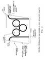
- FIG. 2shows a multi-ring resonator geometry which may be used for an optical spectrum reshaper (OSR);
- OSRoptical spectrum reshaper
- FIG. 3shows typical spectral response from a 3-ring resonator configuration
- FIG. 4defines the peak slope of the transmission profile for the optical spectrum reshaper (OSR).
- the spectral characteristics of the OSRcan be achieved using coupled micro-ring resonators, which are waveguide devices capable of being integrated.
- the micro-ring resonatorsgenerally comprise small (e.g., 4–25 ⁇ m radii) waveguide rings that are coupled to straight waveguide sections, as shown in FIG. 1 .
- a single ring resonatorhas a wavelength dependent transmission profile similar to a Fabry-Perot filter, or a single cavity etalon.
- micro-ring resonatorfunctions as follows.
- Light coupled into the micro-ring, E R1travels around the ring and couples back into the straight section, having picked up a phase according to ⁇ E R exp(i ⁇ ).
- ⁇is a fraction depending on the coupling and the loss
- ⁇is the phase shift caused by traveling around the ring.
- the output electric field at the end of the straight sectionis the interference between the through field E T and the multiplicity of waves, E R1 , E R2 , E R3, . . . that have traveled 1, 2, 3, . . . n times around the micro-ring.
- the interferenceis constructive, the output field has a peak in its transmission spectrum.
- the phase differenceis determined by the size and effective refractive index of the micro-ring.
- the part of the optical signal which is not transmitted at the “through port”is rejected at the “drop port” of the micro-ring resonator apparatus.
- a micro-ring resonator with multiple micro-ringscan have a transmission profile that is similar to a multi-cavity filter, as described in U.S. patent application Ser. No. 10/308,522, filed Dec. 3, 2002 by Daniel Mahgerefteh et al. for HIGH-SPEED TRANSMISSION SYSTEM COMPRISING A COUPLED MULTI-CAVITY OPTICAL SCANNER, which patent application is hereby incorporated herein by reference.
- the bandwidth and slope of the transmission profile of the multi-ring cavity OSRcan be designed by choosing the number, radius, and coupling coefficient of the micro-rings.
- coupled ring resonatorscan be implemented in integrated optics form using both dielectric-based (i.e., glass-based) and semiconductor-based material systems, as described, for example, by J. V. Hryniewicz et al., IEEE Photonics Technology Letters , vol. 12, No. 3, p. 320 (2000), which publication is hereby incorporated herein by reference.
- ring resonator geometrieshave been demonstrated using both planar and vertical coupling schemes.
- a 3-ring resonator, flat-topped, wavelength division multiplexed (WDM) ring resonator devicewas demonstrated by Little Optics ( Advances in Microring Resonators , Brent E. Little, LittleOptics, Inc, Integrated Photonics Research Conference, 2003), which publication is hereby incorporated herein by reference. Similar spectral responses have been demonstrated for ring resonator architectures implemented in a variety of material systems including Silicon, InP, GaAs, glass, Silica, etc.
- FIG. 2shows a preferred implementation of a multi-ring resonator geometry that may be used for CMLTM technology.
- the optical length of the ringis tailored to produce a periodicity of 50 GHz so as to allow the spectral response to be used for wavelength locking to the 50 GHz-spaced ITU grid, which is the common telecommunications standard, and also so as to allow the implementation of a tunable version of the CMLTM system.
- the couplings between the input and output waveguides and the rings, and the couplings between adjacent waveguide rings,can be controlled to produce the desired spectral response.
- FIG. 3is a graph plotting transmission as a function of optical frequency for the OSR which may be formed by the multi-ring resonator.
- the operating point of the input frequency modulated signalis at the edge of the transmission peak of the OSR.
- the input wavelengthis centered on the transmission peak of the multi-ring resonator so as to reduce loss.
- the edge of the transmissionis used to convert the frequency modulated signal to a substantially amplitude modulated signal.
- the transmission edge of the multi-ring resonatorcan also be adapted to convert amplitude modulation to appropriate frequency modulation so as to generate flat chirp and thereby increase the transmission distance of the resulting output signal in fiber with dispersion, as described in U.S. Provisional Patent Application Ser. No. 60/569,769, filed May 10, 2004 by Daniel Mahgerefteh et al. for FLAT CHIRP INDUCED BY AN OPTICAL FILTER EDGE, which patent application is hereby incorporated herein by reference.
- FIG. 4defines the peak slope of the transmission profile for the OSR.
- the peak slope of the transmission peak of the ring resonator OSRis preferably in the range of about 2 dB/GHz to about 3 dB/GHz for a system having a 10 Gb/s bit rate of operation.
- the bandwidth of the ring resonator filteris preferably about 0.8 times to about 1.2 times the bit rate of operation.
- the design parameters of the multi-ring resonatorcan be varied so as to create a transmission profile which is substantially Gaussian.
- a substantially Gaussian shapecan be beneficial.
- the spectral shapeis made to be nearly flat-topped for a low bit rate (e.g., 2.5 Gb/s) application, with a slope near the top of the filter of ⁇ 0.2 dB/GHz.
- the aforementioned CMLTM technologycan be applied at a 10 Gb/s transmission bit rate to distances of greater than 200 km of standard single mode fiber having a net dispersion of 3200 ps/nm, as described in U.S. Provisional Patent Application Ser. No. 60/548,230, filed Feb. 27, 2004 by Yasuhiro Matsui et al. for OPTICAL SYSTEM COMPRISING AN FM SOURCE AND A SPECTRAL RESHAPING ELEMENT, which patent application is hereby incorporated herein by reference. In this case, the requirements for the multi-ring resonator OSR transmission is different, as disclosed in U.S. Provisional Patent Application Ser. No. 60/629,741, filed Nov.
- a key parameter of the OSRis the slope of its logarithmic slope, defined as the ratio of the peak slope in dB/GHz to the frequency offset of the peak slope from the transmission peak in GHz, as shown in FIG. 4 .
- a low bit error rate after transmissionis obtained if the slope of the slope is approximately in the range of 0.38 dB/GHz 2 to 0.6 dB/GHz 2 .
- the slope of the OSR near the center of the transmissionshould be approximately linear.
- Deviations from linearityintroduce distortions in the resulting output eye diagram and increased bit error rate.
- a linear slopecorresponds to a round-topped shaped filter. So, for example, a flat-top filter, which has a near zero slope near the center, is generally not desirable for this long reach application.
- the 3 dB bandwidth of the bandpass OSRshould be in the range of 65% to 90% of the bit rate for this long reach application.
- a wavelength locking circuit for the CMLTM systemis described in U.S. patent application Ser. No. 10/680,607, filed Oct. 6, 2003 by Daniel Mahgerefteh et al. for FLAT DISPERSION FREQUENCY DISCRIMINATOR (FDFD), which patent application is hereby incorporated herein by reference.
- FDFDFLAT DISPERSION FREQUENCY DISCRIMINATOR
- a tap splitter on the input of the straight sectioncouples part of the input light so as to measure input power, P S , and a second tap at the output waveguide can be added to couple part of the output power and measure P T .
- Photodiodes placed to receive the outputs of the two taps, respectively,are then used as part of the wavelength locking circuit such as that described in the aforementioned U.S. patent application Ser. No. 10/680,607.
- the wavelength of the sourceis kept locked to the transmission edge of the multi-ring resonator by adjusting the wavelength of the source in order to keep the ratio P T /P S constant.
- the multi-ring resonator geometryis integrated with the source, to gain the benefit of wafer level fabrication whereby to obtain lower chip costs and increase yield.
- a key advantage of the multi-ring resonator in the CMLTM applicationis that the rejected light does not reflect back into the source, thus eliminating the need for an optical isolator.
- Thismakes it possible to integrate the source, such as a distributed feedback laser (DFB) with the multi-ring resonator OSR.
- Further advantages of an integrated version of the optical discriminatorinclude small size, fast thermal response time and higher wavelength sensitivity (for semiconductor-based implementations). In particular, the possibility of integrating the discriminator function together with the DFB laser on a common chip exists if InP is used as the material system.
- the relative spectral positions of the discriminator and the laser wavelengthcan track with temperature and allow a simple control algorithm to be used. It is, therefore, an embodiment of the present invention to integrate a frequency modulated source, such as a DFB laser, with the multi-ring cavity OSR.
- a frequency modulated sourcesuch as a DFB laser
- a DFB array(comprising a plurality of DFB lasers, each having a different wavelength of operation) is integrated on the same chip with a plurality of multi-ring resonators so as to form a multi-wavelength CMLTM source. These separate wavelengths are then combined by another multiplexer multi-ring resonator.
Landscapes
- Physics & Mathematics (AREA)
- Engineering & Computer Science (AREA)
- Microelectronics & Electronic Packaging (AREA)
- General Physics & Mathematics (AREA)
- Optics & Photonics (AREA)
- Optical Communication System (AREA)
- Semiconductor Lasers (AREA)
Abstract
Description
Claims (22)
Priority Applications (3)
| Application Number | Priority Date | Filing Date | Title |
|---|---|---|---|
| US11/015,591US7280721B2 (en) | 2002-11-06 | 2004-12-17 | Multi-ring resonator implementation of optical spectrum reshaper for chirp managed laser technology |
| US11/093,461US7558488B2 (en) | 2002-11-06 | 2005-03-30 | Reach extension by using external Bragg grating for spectral filtering |
| US11/702,436US7502532B2 (en) | 2002-11-06 | 2007-02-05 | Multi-ring resonator implementation of optical spectrum reshaper for chirp managed laser technology |
Applications Claiming Priority (9)
| Application Number | Priority Date | Filing Date | Title |
|---|---|---|---|
| US10/289,944US6963685B2 (en) | 2002-07-09 | 2002-11-06 | Power source for a dispersion compensation fiber optic system |
| US10/308,522US7663762B2 (en) | 2002-07-09 | 2002-12-03 | High-speed transmission system comprising a coupled multi-cavity optical discriminator |
| US10/680,607US7054538B2 (en) | 2002-10-04 | 2003-10-06 | Flat dispersion frequency discriminator (FDFD) |
| US53047903P | 2003-12-17 | 2003-12-17 | |
| US54823004P | 2004-02-27 | 2004-02-27 | |
| US56976904P | 2004-05-10 | 2004-05-10 | |
| US10/933,081US7406267B2 (en) | 2002-11-06 | 2004-09-02 | Method and apparatus for transmitting a signal using thermal chirp management of a directly modulated transmitter |
| US62974104P | 2004-11-19 | 2004-11-19 | |
| US11/015,591US7280721B2 (en) | 2002-11-06 | 2004-12-17 | Multi-ring resonator implementation of optical spectrum reshaper for chirp managed laser technology |
Related Parent Applications (5)
| Application Number | Title | Priority Date | Filing Date |
|---|---|---|---|
| US10/289,944Continuation-In-PartUS6963685B2 (en) | 2002-07-09 | 2002-11-06 | Power source for a dispersion compensation fiber optic system |
| US10/308,522Continuation-In-PartUS7663762B2 (en) | 2002-07-09 | 2002-12-03 | High-speed transmission system comprising a coupled multi-cavity optical discriminator |
| US10/680,607Continuation-In-PartUS7054538B2 (en) | 2002-10-04 | 2003-10-06 | Flat dispersion frequency discriminator (FDFD) |
| US10/933,081Continuation-In-PartUS7406267B2 (en) | 2002-11-06 | 2004-09-02 | Method and apparatus for transmitting a signal using thermal chirp management of a directly modulated transmitter |
| US11/016,466Continuation-In-PartUS7356264B2 (en) | 2002-11-06 | 2004-12-17 | Chirp managed laser with electronic pre-distortion |
Related Child Applications (3)
| Application Number | Title | Priority Date | Filing Date |
|---|---|---|---|
| US11/015,686Continuation-In-PartUS7376352B2 (en) | 2002-11-06 | 2004-12-17 | Chirp managed laser fiber optic system including an adaptive receiver |
| US11/093,461Continuation-In-PartUS7558488B2 (en) | 2002-11-06 | 2005-03-30 | Reach extension by using external Bragg grating for spectral filtering |
| US11/702,436ContinuationUS7502532B2 (en) | 2002-11-06 | 2007-02-05 | Multi-ring resonator implementation of optical spectrum reshaper for chirp managed laser technology |
Publications (3)
| Publication Number | Publication Date |
|---|---|
| US20050175356A1 US20050175356A1 (en) | 2005-08-11 |
| US20060228120A9 US20060228120A9 (en) | 2006-10-12 |
| US7280721B2true US7280721B2 (en) | 2007-10-09 |
Family
ID=34831556
Family Applications (2)
| Application Number | Title | Priority Date | Filing Date |
|---|---|---|---|
| US11/015,591Expired - LifetimeUS7280721B2 (en) | 2002-11-06 | 2004-12-17 | Multi-ring resonator implementation of optical spectrum reshaper for chirp managed laser technology |
| US11/702,436Expired - LifetimeUS7502532B2 (en) | 2002-11-06 | 2007-02-05 | Multi-ring resonator implementation of optical spectrum reshaper for chirp managed laser technology |
Family Applications After (1)
| Application Number | Title | Priority Date | Filing Date |
|---|---|---|---|
| US11/702,436Expired - LifetimeUS7502532B2 (en) | 2002-11-06 | 2007-02-05 | Multi-ring resonator implementation of optical spectrum reshaper for chirp managed laser technology |
Country Status (1)
| Country | Link |
|---|---|
| US (2) | US7280721B2 (en) |
Cited By (46)
| Publication number | Priority date | Publication date | Assignee | Title |
|---|---|---|---|---|
| US20050129072A1 (en)* | 2003-02-25 | 2005-06-16 | Parviz Tayebati | Optical beam steering for tunable laser applications |
| US20050271392A1 (en)* | 2002-11-06 | 2005-12-08 | Yasuhiro Matsui | Reach extension by using external bragg grating for spectral filtering |
| US20060002718A1 (en)* | 2002-11-06 | 2006-01-05 | Yasuhiro Matsui | Chirp managed directly modulated laser with bandwidth limiting optical spectrum reshaper |
| US20060018666A1 (en)* | 2002-11-06 | 2006-01-26 | Yasuhiro Matsui | Adiabatically frequency modulated source |
| US20060029396A1 (en)* | 2002-11-06 | 2006-02-09 | Daniel Mahgerefteh | Flat-topped chirp induced by optical filter edge |
| US20060039502A1 (en)* | 2002-11-06 | 2006-02-23 | Daniel Mahgerefteh | Phase correlated quadrature amplitude modulation |
| US20060078338A1 (en)* | 2002-11-06 | 2006-04-13 | Bart Johnson | Thermal chirp compensation systems for a chirp managed directly modulated laser (CML™) data Link |
| US20060233556A1 (en)* | 2002-07-09 | 2006-10-19 | Daniel Mahgerefteh | Power source for a dispersion compensation fiber optic system |
| US20060274993A1 (en)* | 2002-10-04 | 2006-12-07 | Daniel Mahgerefteh | Flat dispersion frequency discriminator (FDFD) |
| US20070012860A1 (en)* | 2005-05-05 | 2007-01-18 | Daniel Mahgerefteh | Optical source with ultra-low relative intensity noise (RIN) |
| US20070147847A1 (en)* | 2004-09-02 | 2007-06-28 | Xueyan Zheng | Method and apparatus for transmitting a signal using a chirp managed laser (CML) and an optical spectrum reshaper (OSR) before an optical receiver |
| US20070183792A1 (en)* | 2002-12-03 | 2007-08-09 | Mccallion Kevin | Widely tunable, dispersion tolerant transmitter |
| US20070286608A1 (en)* | 2002-12-03 | 2007-12-13 | Yasuhiro Matsui | Optical FM source based on intra-cavity phase and amplitude modulation in lasers |
| US20080002990A1 (en)* | 2002-11-06 | 2008-01-03 | Mccallion Kevin | Multi-ring resonator implementation of optical spectrum reshaper for chirp managed laser technology |
| US20080025731A1 (en)* | 2002-12-03 | 2008-01-31 | Daniel Mahgerefteh | Versatile compact transmitter for generation of advanced modulation formats |
| US20080158639A1 (en)* | 2006-10-24 | 2008-07-03 | Mccallion Kevin | Spectral response modification via spatial filtering with optical fiber |
| US20080159751A1 (en)* | 2002-12-03 | 2008-07-03 | Yasuhiro Matsui | Optical transmission using semiconductor optical amplifier (SOA) |
| US20080166130A1 (en)* | 2002-07-09 | 2008-07-10 | Daniel Mahgerefteh | Wavelength division multiplexing source using multifunctional filters |
| US20080181619A1 (en)* | 2007-01-22 | 2008-07-31 | Finisar Corporation | Method and apparatus for generating signals with increased dispersion tolerance using a directly modulated laser transmitter |
| US20080193143A1 (en)* | 2002-12-03 | 2008-08-14 | Daniel Mahgerefteh | Chirp-managed, electroabsorption-modulated laser |
| US20080240180A1 (en)* | 2002-12-03 | 2008-10-02 | Finisar Corporation | Optical fm source based on intra-cavity phase and amplitude modulation in lasers |
| US20080240733A1 (en)* | 2007-04-02 | 2008-10-02 | Finisar Corporation | Dispersion compensator for frequency reshaped optical signals |
| US20080247763A1 (en)* | 2007-04-06 | 2008-10-09 | Finisar Corporation | Chirped laser with passive filter element for differential phase shift keying generation |
| US20080247765A1 (en)* | 2002-07-09 | 2008-10-09 | Finisar Corporation | Power source for a dispersion compensation fiber optic system |
| US20080285977A1 (en)* | 2007-05-04 | 2008-11-20 | Massachusetts Institute Of Technology | Method and apparatus for transmitting optical signals |
| US20090003842A1 (en)* | 2007-04-06 | 2009-01-01 | Finisar Corporation | Chirped laser with passive filter element for differential phase shift keying generation |
| US20090016740A1 (en)* | 2002-12-03 | 2009-01-15 | Daniel Mahgerefteh | Method and apparatus for compensating for fiber nonlinearity in a transmission system |
| US20090041073A1 (en)* | 2007-04-13 | 2009-02-12 | Finisar Corporation | Dbr laser with improved thermal tuning efficiency |
| US20090060526A1 (en)* | 2002-12-03 | 2009-03-05 | Finisar Corporation | Optical fm source based on intra-cavity phase and amplitude modulation in lasers |
| US20090074020A1 (en)* | 2007-05-14 | 2009-03-19 | Finisar Corporation | DBR laser with improved thermal tuning effciency |
| US20090080905A1 (en)* | 2002-12-03 | 2009-03-26 | Nils Anders Olsson | High power, low distortion directly modulated laser transmitter |
| US7542683B2 (en) | 2002-12-03 | 2009-06-02 | Finisar Corporation | Chirp Managed Laser (CML) transmitter |
| US20090238224A1 (en)* | 2008-03-21 | 2009-09-24 | Finisar Corporation | Directly Modulated Laser with Isolated Modulated Gain Electrode for Improved Frequency Modulation |
| US20090251759A1 (en)* | 2006-06-10 | 2009-10-08 | Domash Lawrence H | Materials, thin films, optical filters, and devices including same |
| US20090269069A1 (en)* | 2008-04-25 | 2009-10-29 | Finisar Corporation | Passive wave division multiplexed transmitter having a directly modulated laser array |
| US7941057B2 (en) | 2006-12-28 | 2011-05-10 | Finisar Corporation | Integral phase rule for reducing dispersion errors in an adiabatically chirped amplitude modulated signal |
| US7962045B2 (en) | 2006-12-22 | 2011-06-14 | Finisar Corporation | Optical transmitter having a widely tunable directly modulated laser and periodic optical spectrum reshaping element |
| US7962044B2 (en) | 2007-02-02 | 2011-06-14 | Finisar Corporation | Temperature stabilizing packaging for optoelectronic components in a transmitter module |
| US7991291B2 (en) | 2007-02-08 | 2011-08-02 | Finisar Corporation | WDM PON based on DML |
| US8027593B2 (en) | 2007-02-08 | 2011-09-27 | Finisar Corporation | Slow chirp compensation for enhanced signal bandwidth and transmission performances in directly modulated lasers |
| CN102411141A (en)* | 2011-08-11 | 2012-04-11 | 太原理工大学 | Chaotic light emission device for chaotic laser ranging |
| US8160455B2 (en) | 2008-01-22 | 2012-04-17 | Finisar Corporation | Method and apparatus for generating signals with increased dispersion tolerance using a directly modulated laser transmitter |
| US8199785B2 (en) | 2009-06-30 | 2012-06-12 | Finisar Corporation | Thermal chirp compensation in a chirp managed laser |
| US8792531B2 (en) | 2003-02-25 | 2014-07-29 | Finisar Corporation | Optical beam steering for tunable laser applications |
| US9548878B2 (en) | 2008-03-12 | 2017-01-17 | Hypres, Inc. | Digital radio frequency transceiver system and method |
| US9806820B2 (en) | 2013-12-31 | 2017-10-31 | Huawei Technologies Co., Ltd. | Optical transmitter and optical transmission method |
Families Citing this family (28)
| Publication number | Priority date | Publication date | Assignee | Title |
|---|---|---|---|---|
| US7352968B2 (en)* | 2002-11-06 | 2008-04-01 | Finisar Corporation | Chirped managed, wavelength multiplexed, directly modulated sources using an arrayed waveguide grating (AWG) as multi-wavelength discriminator |
| US7187827B2 (en)* | 2005-04-26 | 2007-03-06 | Harris Corporation | Coupled waveguide optical microresonator |
| US7424187B2 (en)* | 2005-04-26 | 2008-09-09 | Harris Corporation | Optical microresonator with resonant waveguide imparting polarization |
| US7236679B2 (en)* | 2005-04-26 | 2007-06-26 | Harris Corporation | Optical microresonator coupling system and associated method |
| US7224866B2 (en)* | 2005-04-26 | 2007-05-29 | Harris Corporation | Apparatus and method for forming an optical microresonator |
| US7346241B2 (en)* | 2005-04-26 | 2008-03-18 | Harris Corporation | Optical microresonator with microcylinder and circumferential coating forming resonant waveguides |
| US7184629B2 (en)* | 2005-04-26 | 2007-02-27 | Harris Corporation | Spiral waveguide slow wave resonator structure |
| US7286734B2 (en)* | 2005-04-26 | 2007-10-23 | Harris Corporation | Optical microresonator with coupling elements for changing light direction |
| JP2008004633A (en)* | 2006-06-20 | 2008-01-10 | Nec Corp | Optical module and packaging method |
| ATE515115T1 (en)* | 2006-11-09 | 2011-07-15 | Pgt Photonics Spa | METHOD AND DEVICE FOR FLAWLESS TUNABLE OPTICAL FILTERING |
| ATE531150T1 (en)* | 2006-11-09 | 2011-11-15 | Mosaid Technologies Inc | METHOD AND DEVICE FOR FLAWLESS TUNABLE OPTICAL FILTERING |
| JP2008251673A (en)* | 2007-03-29 | 2008-10-16 | Nec Corp | Optical device and manufacturing method therefor |
| US7421168B1 (en) | 2007-07-02 | 2008-09-02 | Northrop Grumman Systems Corporation | Integrated optical channelizer |
| US20090046748A1 (en)* | 2007-08-14 | 2009-02-19 | Sumitomo Electric Industries, Ltd. | Light-emitting device with precisely tuned and narrowed spectral width of optical output and an optical signal source providing the same |
| US8139904B2 (en)* | 2007-09-18 | 2012-03-20 | International Business Machines Corporation | Method and apparatus for implementing optical deflection switching using coupled resonators |
| US8606055B2 (en)* | 2009-11-06 | 2013-12-10 | Cornell University | Pin diode tuned multiple ring waveguide resonant optical cavity switch and method |
| CN101840029B (en)* | 2010-04-28 | 2012-07-11 | 中国科学院半导体研究所 | An Integrated Reconfigurable Optical Add-Drop Multiplexer |
| US8781336B1 (en)* | 2011-02-10 | 2014-07-15 | Finisar Corporation | Optical filter for use in a laser transmitter |
| CN102780529B (en)* | 2012-07-13 | 2015-09-30 | 青岛海信宽带多媒体技术有限公司 | EPON and optical line terminal optical module thereof |
| US10447409B2 (en) | 2013-06-21 | 2019-10-15 | Northrop Grumman Systems Corporation | Optical channelizer for W-band detection |
| US10429676B2 (en) | 2015-07-23 | 2019-10-01 | Hewlett Packard Enterprise Development Lp | Ring waveguide modulators |
| EP3500892A4 (en) | 2016-08-18 | 2020-04-08 | The Regents of The University of California | COMPLETE MICROWAVE STABILIZATION OF MICRORESONATOR-BASED OPTICAL FREQUENCY COMBS |
| CN110168444B (en) | 2016-10-31 | 2023-02-14 | 加利福尼亚大学董事会 | Frequency comb generation for adiabatic dispersion management |
| CA3061993A1 (en) | 2017-05-22 | 2018-11-29 | Brolis Sensor Technology, Uab | Tunable hybrid iii-v/ iv laser sensor system-on-a-chip for real-time monitoring of a blood constituent concentration level |
| US11105979B2 (en) | 2017-08-30 | 2021-08-31 | The Regents Of The University Of California | Graphene microcavity frequency combs and related methods of manufacturing |
| EP3747092B1 (en) | 2018-02-02 | 2025-03-05 | Brolis Sensor Technology, UAB | Wavelength determination for widely tunable lasers and laser systems thereof |
| WO2020097241A1 (en) | 2018-11-06 | 2020-05-14 | The Regents Of The University Of California | Chip-scale frequency-comb assisted coherent lidar ranging with sub-micrometer precision |
| CN114355507B (en)* | 2022-01-25 | 2023-12-05 | 吉林大学 | Micro-ring resonator based on inverted ridge type silicon dioxide/polymer mixed waveguide and preparation method thereof |
Citations (18)
| Publication number | Priority date | Publication date | Assignee | Title |
|---|---|---|---|---|
| GB2107147A (en) | 1981-09-03 | 1983-04-20 | Standard Telephones Cables Ltd | Optical requency modulation system |
| US4805235A (en) | 1986-02-17 | 1989-02-14 | Nec Corporation | Optical transmitter comprising an optical frequency discriminator |
| US5371625A (en) | 1992-02-01 | 1994-12-06 | Alcatel N.V. | System for optically transmitting digital communications over an optical fiber with dispersion at the operating wavelength |
| US5416629A (en) | 1992-12-02 | 1995-05-16 | General Instrument Corporation | Intensity modulated digital optical communications using a frequency modulated signal laser |
| US5920416A (en) | 1996-02-23 | 1999-07-06 | Cit Alcatel | Optical method of transmitting digital data |
| US6104851A (en) | 1998-04-24 | 2000-08-15 | Mahgerefteh; Daniel | Transmission system comprising a semiconductor laser and a fiber grating discriminator |
| US6115403A (en) | 1997-07-22 | 2000-09-05 | Ciena Corporation | Directly modulated semiconductor laser having reduced chirp |
| US6298186B1 (en) | 2000-07-07 | 2001-10-02 | Metrophotonics Inc. | Planar waveguide grating device and method having a passband with a flat-top and sharp-transitions |
| US6331991B1 (en) | 1998-07-17 | 2001-12-18 | The United States Of America As Represented By The National Security Agency | Transmission system using a semiconductor laser and a fiber grating discriminator |
| US20020176659A1 (en)* | 2001-05-21 | 2002-11-28 | Jds Uniphase Corporation | Dynamically tunable resonator for use in a chromatic dispersion compensator |
| US6563623B1 (en) | 1998-07-20 | 2003-05-13 | Alcatel | System for transmitting optical data |
| US20040008933A1 (en) | 2002-07-09 | 2004-01-15 | Daniel Mahgerefteh | High-speed transmission system comprising a coupled multi-cavity optical discriminator |
| US20040096221A1 (en) | 2002-07-09 | 2004-05-20 | Daniel Mahgerefteh | Wavelength division multiplexing source using multifunctional filters |
| US20050111852A1 (en)* | 2002-11-06 | 2005-05-26 | Daniel Mahgerefteh | Method and apparatus for transmitting a signal using thermal chirp management of a directly modulated transmitter |
| US6963685B2 (en) | 2002-07-09 | 2005-11-08 | Daniel Mahgerefteh | Power source for a dispersion compensation fiber optic system |
| US20060029358A1 (en) | 2002-11-06 | 2006-02-09 | Daniel Mahgerefteh | Optical system comprising an FM source and a spectral reshaping element |
| US20060029396A1 (en) | 2002-11-06 | 2006-02-09 | Daniel Mahgerefteh | Flat-topped chirp induced by optical filter edge |
| US7054538B2 (en) | 2002-10-04 | 2006-05-30 | Azna Llc | Flat dispersion frequency discriminator (FDFD) |
Family Cites Families (79)
| Publication number | Priority date | Publication date | Assignee | Title |
|---|---|---|---|---|
| US3324295A (en) | 1963-11-07 | 1967-06-06 | Research Corp | Frequency modulation discriminator for optical signals |
| US3999105A (en) | 1974-04-19 | 1976-12-21 | International Business Machines Corporation | Liquid encapsulated integrated circuit package |
| US4038600A (en) | 1976-02-17 | 1977-07-26 | Westinghouse Electric Corporation | Power control on satellite uplinks |
| JPS62189832A (en) | 1986-02-17 | 1987-08-19 | Nec Corp | Optical transmitter |
| CA1279414C (en) | 1987-06-26 | 1991-01-22 | Makoto Nishio | Apparatus for discriminating an optical signal from others and an apparatus for tuning an optical wavelength filter used in the same |
| US5177750A (en) | 1991-07-30 | 1993-01-05 | Hewlett-Packard Company | Misalignment-tolerant, grating-tuned external-cavity laser with enhanced longitudinal mode selectivity |
| US5412474A (en) | 1992-05-08 | 1995-05-02 | Smithsonian Institution | System for measuring distance between two points using a variable frequency coherent source |
| US5293545A (en) | 1992-07-27 | 1994-03-08 | General Instrument Corporation | Optical source with reduced relative intensity noise |
| DE4234599A1 (en) | 1992-08-22 | 1994-02-24 | Sel Alcatel Ag | Optical transmitter |
| US5465264A (en) | 1993-11-22 | 1995-11-07 | Xerox Corporation | Electronic simulation for compensating laser diode thermal effects |
| US5856980A (en) | 1994-12-08 | 1999-01-05 | Intel Corporation | Baseband encoding method and apparatus for increasing the transmission rate over a communication medium |
| US5592327A (en) | 1994-12-16 | 1997-01-07 | Clark-Mxr, Inc. | Regenerative amplifier incorporating a spectral filter within the resonant cavity |
| US5477368A (en) | 1994-12-29 | 1995-12-19 | At&T Corp. | High power lightwave transmitter using highly saturated amplifier for residual AM suppression |
| TW304310B (en) | 1995-05-31 | 1997-05-01 | Siemens Ag | |
| US5737104A (en) | 1995-12-18 | 1998-04-07 | Dicon Fiberoptics | Wavelength division multiplexer and demultiplexer |
| US5953139A (en) | 1996-03-06 | 1999-09-14 | Cfx Communications Systems, Llc | Wavelength division multiplexing system |
| US5805235A (en) | 1996-04-03 | 1998-09-08 | Hyundai Electronics America | Bookmarking television program and channel selections |
| US5777773A (en) | 1996-10-31 | 1998-07-07 | Northern Telecom Limited | Optical frequency control system and method |
| US6096496A (en) | 1997-06-19 | 2000-08-01 | Frankel; Robert D. | Supports incorporating vertical cavity emitting lasers and tracking apparatus for use in combinatorial synthesis |
| JP3347644B2 (en) | 1997-07-11 | 2002-11-20 | サンテック株式会社 | Laser light source device |
| DE19734957C1 (en) | 1997-08-13 | 1998-12-24 | Lucent Tech Network Sys Gmbh | Wavelength stabilisation method for multi-channel optical transmission system |
| US6081361A (en) | 1997-10-17 | 2000-06-27 | Lucent Technologies Inc. | Sub-carrier multiplexing in broadband optical networks |
| US5974209A (en) | 1998-04-30 | 1999-10-26 | Cho; Pak Shing | System comprising an electroabsorption modulator and an optical discriminator |
| GB9813412D0 (en) | 1998-06-23 | 1998-08-19 | Cambrian Systems Corp | Optical FSK modulation and demodulation based on the thermal chirp for optical path overhead transfer using asymmetrical mach-zehnder interferometer |
| US6222861B1 (en) | 1998-09-03 | 2001-04-24 | Photonic Solutions, Inc. | Method and apparatus for controlling the wavelength of a laser |
| JP2000105313A (en) | 1998-09-30 | 2000-04-11 | Kazuro Kikuchi | Dispersion compensator |
| EP1142179A1 (en) | 1998-12-15 | 2001-10-10 | Ortel Corporation | Circuit for suppressing noise and distortion in linear fiber optic links |
| US6353623B1 (en) | 1999-01-04 | 2002-03-05 | Uniphase Telecommunications Products, Inc. | Temperature-corrected wavelength monitoring and control apparatus |
| JP4545266B2 (en) | 1999-02-15 | 2010-09-15 | 富士通オプティカルコンポーネンツ株式会社 | Optical module |
| US6359716B1 (en) | 1999-02-24 | 2002-03-19 | Massachusetts Institute Of Technology | All-optical analog FM optical receiver |
| US6473214B1 (en) | 1999-04-01 | 2002-10-29 | Nortel Networks Limited | Methods of and apparatus for optical signal transmission |
| US6580734B1 (en) | 1999-07-07 | 2003-06-17 | Cyoptics Ltd. | Laser wavelength stabilization |
| JP3784585B2 (en) | 1999-08-26 | 2006-06-14 | 富士通株式会社 | Method, optical device and system for optical fiber transmission |
| WO2001017076A2 (en) | 1999-09-02 | 2001-03-08 | Agility Communications, Inc. | Tunable laser source with integrated optical amplifier |
| US6687278B1 (en) | 1999-09-02 | 2004-02-03 | Agility Communications, Inc. | Method of generating an optical signal with a tunable laser source with integrated optical amplifier |
| CA2381766A1 (en) | 1999-09-03 | 2001-03-15 | The Regents Of The University Of California | Tunable laser source with integrated optical modulator |
| US6519065B1 (en) | 1999-11-05 | 2003-02-11 | Jds Fitel Inc. | Chromatic dispersion compensation device |
| US20030128980A1 (en)* | 2002-11-27 | 2003-07-10 | Abeles Joseph H. | Channelizer switch |
| DE60024404T2 (en) | 2000-02-02 | 2006-08-03 | Telefonaktiebolaget Lm Ericsson (Publ) | Method and device for predistorting a digital signal |
| JP2001284711A (en) | 2000-03-31 | 2001-10-12 | Hitachi Ltd | Optical transmission device and optical system using the same |
| US6834134B2 (en) | 2000-04-11 | 2004-12-21 | 3M Innovative Properties Company | Method and apparatus for generating frequency modulated pulses |
| JP2001320328A (en) | 2000-05-02 | 2001-11-16 | Oyokoden Lab Co Ltd | Optical communication method |
| US6943951B2 (en) | 2000-05-10 | 2005-09-13 | Oyokoden Lab Co., Ltd. | Optical component and dispersion compensation method |
| US6650667B2 (en) | 2000-05-16 | 2003-11-18 | The Furukawa Electric Co., Ltd. | Semiconductor laser apparatus, semiconductor laser module, optical transmitter and wavelength division multiplexing communication system |
| GB2380807B (en) | 2000-08-04 | 2004-07-07 | Jr Joseph David Evankow | Apparatus for polarization-independent optical polarization scrambler and a method for use therein |
| US6577013B1 (en) | 2000-09-05 | 2003-06-10 | Amkor Technology, Inc. | Chip size semiconductor packages with stacked dies |
| JP2002311235A (en) | 2000-09-14 | 2002-10-23 | Oyokoden Lab Co Ltd | Composite light diffusion compensating element and light diffusion compensating method using the same |
| US7050723B2 (en)* | 2001-01-19 | 2006-05-23 | Nippon Telegraph And Telephone Corporation | Laser oscillator, optical communication method and system |
| JP3879411B2 (en) | 2001-02-14 | 2007-02-14 | 日本電気株式会社 | Dispersion compensator |
| US6778307B2 (en) | 2001-02-21 | 2004-08-17 | Beyond 3, Inc. | Method and system for performing swept-wavelength measurements within an optical system |
| EP1235403B1 (en) | 2001-02-22 | 2012-12-05 | Panasonic Corporation | Combined frequency and amplitude modulation |
| JP2002267998A (en) | 2001-03-07 | 2002-09-18 | Sumitomo Osaka Cement Co Ltd | Wavelength dispersion compensation module, optical receiving circuit, and optical communication system |
| JP2002267834A (en) | 2001-03-07 | 2002-09-18 | Oyokoden Lab Co Ltd | Optical component, optical dispersion compensation device using the component and method for compensating optical dispersion |
| US6658031B2 (en) | 2001-07-06 | 2003-12-02 | Intel Corporation | Laser apparatus with active thermal tuning of external cavity |
| US6621836B2 (en) | 2001-03-29 | 2003-09-16 | The United States Of America As Represented By The Secretary Of The Navy | Tunable multi-frequency vertical cavity surface emitting laser |
| KR100408187B1 (en) | 2001-04-24 | 2003-12-03 | 한국과학기술원 | Transmission system of frequency modulated optical signal and Power and optical frequency monitoring system of frequency modulated optical signal |
| US7076170B2 (en) | 2001-05-14 | 2006-07-11 | University Of Maryland, Baltimore County | System and method for generating analog transmission signals |
| US6778318B2 (en)* | 2001-06-29 | 2004-08-17 | Hrl Laboratories, Llc | Optical-to-wireless WDM converter |
| US6631146B2 (en) | 2001-07-06 | 2003-10-07 | Intel Corporation | Tunable laser control system |
| JP3731505B2 (en) | 2001-07-18 | 2006-01-05 | 日本電気株式会社 | Optical receiver, optical data signal waveform optimization method, and optical data signal waveform optimization program |
| US6836487B1 (en) | 2001-08-31 | 2004-12-28 | Nlight Photonics Corporation | Spectrally tailored raman pump laser |
| US6950452B2 (en) | 2001-09-28 | 2005-09-27 | The Furukawa Electric Co., Ltd. | Semiconductor laser module and method for simultaneously reducing relative intensity noise (RIN) and stimulated brillouin scattering (SBS) |
| US7283694B2 (en) | 2001-10-09 | 2007-10-16 | Infinera Corporation | Transmitter photonic integrated circuits (TxPIC) and optical transport networks employing TxPICs |
| US6748133B2 (en) | 2001-11-26 | 2004-06-08 | Alliance Fiber Optic Products, Inc. | Compact multiplexing/demultiplexing modules |
| KR100444176B1 (en) | 2001-12-15 | 2004-08-09 | 한국전자통신연구원 | Optical deflector operated by electric signal and external cavity type of wave length tunable using the same |
| US7209669B2 (en) | 2002-02-01 | 2007-04-24 | Lucent Technologies Inc. | Method and apparatus for synchronizing a pulse carver and a data modulator for optical telecommunication |
| GB0206226D0 (en) | 2002-03-16 | 2002-05-01 | Intense Photonics Ltd | Electro-absorption modulator with broad optical bandwidth |
| US20030193974A1 (en) | 2002-04-16 | 2003-10-16 | Robert Frankel | Tunable multi-wavelength laser device |
| US6760142B2 (en) | 2002-05-13 | 2004-07-06 | Lucent Technologies Inc. | Delay interferometer optical pulse generator |
| US6778309B2 (en) | 2002-08-22 | 2004-08-17 | Triquint Technology Holding Co. | Electroabsorption modulator with tunable chirp |
| US20040076199A1 (en) | 2002-08-22 | 2004-04-22 | Agility Communications, Inc. | Chirp control of integrated laser-modulators having multiple sections |
| US20040081386A1 (en)* | 2002-10-25 | 2004-04-29 | Morse Michael T. | Method and apparatus for modulating an optical beam with a ring resonator having a charge modulated region |
| US7280721B2 (en) | 2002-11-06 | 2007-10-09 | Azna Llc | Multi-ring resonator implementation of optical spectrum reshaper for chirp managed laser technology |
| US7536113B2 (en) | 2002-11-06 | 2009-05-19 | Finisar Corporation | Chirp managed directly modulated laser with bandwidth limiting optical spectrum reshaper |
| US7433605B2 (en) | 2002-11-06 | 2008-10-07 | Finisar Corporation | Adiabatic frequency modulated transmitter with negative chirp |
| US20060029397A1 (en) | 2002-11-06 | 2006-02-09 | Daniel Mahgerefteh | Method and apparatus for transmitting a signal using simultaneous FM and AM modulation |
| US7564889B2 (en) | 2002-11-06 | 2009-07-21 | Finisar Corporation | Adiabatically frequency modulated source |
| US6947206B2 (en) | 2003-07-18 | 2005-09-20 | Kailight Photonics, Inc. | All-optical, tunable regenerator, reshaper and wavelength converter |
| US20050271394A1 (en) | 2004-06-02 | 2005-12-08 | James Whiteaway | Filter to improve dispersion tolerance for optical transmission |
- 2004
- 2004-12-17USUS11/015,591patent/US7280721B2/ennot_activeExpired - Lifetime
- 2007
- 2007-02-05USUS11/702,436patent/US7502532B2/ennot_activeExpired - Lifetime
Patent Citations (19)
| Publication number | Priority date | Publication date | Assignee | Title |
|---|---|---|---|---|
| US4561119A (en) | 1981-09-03 | 1985-12-24 | International Standard Electric Corporation | Optical frequency modulation system |
| GB2107147A (en) | 1981-09-03 | 1983-04-20 | Standard Telephones Cables Ltd | Optical requency modulation system |
| US4805235A (en) | 1986-02-17 | 1989-02-14 | Nec Corporation | Optical transmitter comprising an optical frequency discriminator |
| US5371625A (en) | 1992-02-01 | 1994-12-06 | Alcatel N.V. | System for optically transmitting digital communications over an optical fiber with dispersion at the operating wavelength |
| US5416629A (en) | 1992-12-02 | 1995-05-16 | General Instrument Corporation | Intensity modulated digital optical communications using a frequency modulated signal laser |
| US5920416A (en) | 1996-02-23 | 1999-07-06 | Cit Alcatel | Optical method of transmitting digital data |
| US6115403A (en) | 1997-07-22 | 2000-09-05 | Ciena Corporation | Directly modulated semiconductor laser having reduced chirp |
| US6104851A (en) | 1998-04-24 | 2000-08-15 | Mahgerefteh; Daniel | Transmission system comprising a semiconductor laser and a fiber grating discriminator |
| US6331991B1 (en) | 1998-07-17 | 2001-12-18 | The United States Of America As Represented By The National Security Agency | Transmission system using a semiconductor laser and a fiber grating discriminator |
| US6563623B1 (en) | 1998-07-20 | 2003-05-13 | Alcatel | System for transmitting optical data |
| US6298186B1 (en) | 2000-07-07 | 2001-10-02 | Metrophotonics Inc. | Planar waveguide grating device and method having a passband with a flat-top and sharp-transitions |
| US20020176659A1 (en)* | 2001-05-21 | 2002-11-28 | Jds Uniphase Corporation | Dynamically tunable resonator for use in a chromatic dispersion compensator |
| US20040008933A1 (en) | 2002-07-09 | 2004-01-15 | Daniel Mahgerefteh | High-speed transmission system comprising a coupled multi-cavity optical discriminator |
| US20040096221A1 (en) | 2002-07-09 | 2004-05-20 | Daniel Mahgerefteh | Wavelength division multiplexing source using multifunctional filters |
| US6963685B2 (en) | 2002-07-09 | 2005-11-08 | Daniel Mahgerefteh | Power source for a dispersion compensation fiber optic system |
| US7054538B2 (en) | 2002-10-04 | 2006-05-30 | Azna Llc | Flat dispersion frequency discriminator (FDFD) |
| US20050111852A1 (en)* | 2002-11-06 | 2005-05-26 | Daniel Mahgerefteh | Method and apparatus for transmitting a signal using thermal chirp management of a directly modulated transmitter |
| US20060029358A1 (en) | 2002-11-06 | 2006-02-09 | Daniel Mahgerefteh | Optical system comprising an FM source and a spectral reshaping element |
| US20060029396A1 (en) | 2002-11-06 | 2006-02-09 | Daniel Mahgerefteh | Flat-topped chirp induced by optical filter edge |
Non-Patent Citations (9)
| Title |
|---|
| Corvini, P.J. et al., Computer Simulation of High-Bit-Rate Optical Fiber Transmission Using Single-Frequency Lasers, Journal of Lightwave Technology, Nov. 1987, 1591-1595, vol. LT-5, No. 11. |
| Hyryniewicz, J.V. et al., Higher Order Filter Response in Coupled MicroRing Resonators, IEEE Photonics Technology Letters, Mar. 2000, 320-322, vol. 12, No. 3. |
| Kurtzke C. et al., Impact of Residual Amplitude modulation on the Performance of Disperion-Supported and Dispersion-Mediated Nonlinearity-Enhanced Transmission, Electronics Letters, Jun. 9, 1994, 988, vol. 30, No. 12. |
| Lee, Chang-Hee et al., Transmission of Directly Modulated 2.5-Gb/s Signals Over 250-km of Nondispersion-Shifted Fiber by Using a Spectral Filtering Method, IEEE Photonics Technology Letters, Dec. 1996, 1725-2727, vol. 8, No. 12. |
| Little, B. E., Advances in MicroRing Resonators, LittleOptics, Inc., Integrated Photonics Research Conference 2003. |
| Rasmussen, C.J. et al., Optimum Amplitude and Frequency-Modulation in an Optical Communication System Based on Dispersion Supported Transmission, Electronics Letters, Apr. 27, 1995, 746, vol. 31, No. 9. |
| Shalom, H., et al., On the Various Time Constants of Wavelength Changes of a DFB Laser Under Direct Modulation, IEEE Journal of Quantum Electronics, Oct. 1998, 1816-1822, vol. 34, No. 10. |
| Wedding, B., Analysis of Fibre Transfer Function and Determination of Receiver Frequency Response for Dispersion Supported Transmission, Electronics Letters, Jan. 6 1994, 58, vol. 30, No. 1. |
| Wedding, B., et al., 10-Gb/s Optical Transmission up to 253 km Via Standard Single-Mode Fiber Using the Method of Dispersion-Supported Transmission, Journal of Lightwave Technology, Oct. 1994, 1720; vol. 12, No. 10. |
Cited By (80)
| Publication number | Priority date | Publication date | Assignee | Title |
|---|---|---|---|---|
| US7663762B2 (en) | 2002-07-09 | 2010-02-16 | Finisar Corporation | High-speed transmission system comprising a coupled multi-cavity optical discriminator |
| US7477851B2 (en) | 2002-07-09 | 2009-01-13 | Finisar Corporation | Power source for a dispersion compensation fiber optic system |
| US20080166130A1 (en)* | 2002-07-09 | 2008-07-10 | Daniel Mahgerefteh | Wavelength division multiplexing source using multifunctional filters |
| US7616902B2 (en) | 2002-07-09 | 2009-11-10 | Finisar Corporation | Power source for a dispersion compensation fiber optic system |
| US20080247765A1 (en)* | 2002-07-09 | 2008-10-09 | Finisar Corporation | Power source for a dispersion compensation fiber optic system |
| US7657179B2 (en) | 2002-07-09 | 2010-02-02 | Finisar Corporation | Wavelength division multiplexing source using multifunctional filters |
| US20060233556A1 (en)* | 2002-07-09 | 2006-10-19 | Daniel Mahgerefteh | Power source for a dispersion compensation fiber optic system |
| US7492976B2 (en) | 2002-10-04 | 2009-02-17 | Finisar Corporation | Flat dispersion frequency discriminator (FDFD) |
| US20060274993A1 (en)* | 2002-10-04 | 2006-12-07 | Daniel Mahgerefteh | Flat dispersion frequency discriminator (FDFD) |
| US20060039502A1 (en)* | 2002-11-06 | 2006-02-23 | Daniel Mahgerefteh | Phase correlated quadrature amplitude modulation |
| US7742542B2 (en) | 2002-11-06 | 2010-06-22 | Finisar Corporation | Phase correlated quadrature amplitude modulation |
| US20060078338A1 (en)* | 2002-11-06 | 2006-04-13 | Bart Johnson | Thermal chirp compensation systems for a chirp managed directly modulated laser (CML™) data Link |
| US20060029396A1 (en)* | 2002-11-06 | 2006-02-09 | Daniel Mahgerefteh | Flat-topped chirp induced by optical filter edge |
| US20080002990A1 (en)* | 2002-11-06 | 2008-01-03 | Mccallion Kevin | Multi-ring resonator implementation of optical spectrum reshaper for chirp managed laser technology |
| US7564889B2 (en) | 2002-11-06 | 2009-07-21 | Finisar Corporation | Adiabatically frequency modulated source |
| US7558488B2 (en) | 2002-11-06 | 2009-07-07 | Finisar Corporation | Reach extension by using external Bragg grating for spectral filtering |
| US7536113B2 (en)* | 2002-11-06 | 2009-05-19 | Finisar Corporation | Chirp managed directly modulated laser with bandwidth limiting optical spectrum reshaper |
| US20060018666A1 (en)* | 2002-11-06 | 2006-01-26 | Yasuhiro Matsui | Adiabatically frequency modulated source |
| US7505694B2 (en) | 2002-11-06 | 2009-03-17 | Finisar Corporation | Thermal chirp compensation systems for a chirp managed directly modulated laser (CML™) data link |
| US7502532B2 (en)* | 2002-11-06 | 2009-03-10 | Finisar Corporation | Multi-ring resonator implementation of optical spectrum reshaper for chirp managed laser technology |
| US20060002718A1 (en)* | 2002-11-06 | 2006-01-05 | Yasuhiro Matsui | Chirp managed directly modulated laser with bandwidth limiting optical spectrum reshaper |
| US20050271392A1 (en)* | 2002-11-06 | 2005-12-08 | Yasuhiro Matsui | Reach extension by using external bragg grating for spectral filtering |
| US20080240180A1 (en)* | 2002-12-03 | 2008-10-02 | Finisar Corporation | Optical fm source based on intra-cavity phase and amplitude modulation in lasers |
| US7809280B2 (en) | 2002-12-03 | 2010-10-05 | Finisar Corporation | Chirp-managed, electroabsorption-modulated laser |
| US20070286608A1 (en)* | 2002-12-03 | 2007-12-13 | Yasuhiro Matsui | Optical FM source based on intra-cavity phase and amplitude modulation in lasers |
| US7925172B2 (en) | 2002-12-03 | 2011-04-12 | Finisar Corporation | High power, low distortion directly modulated laser transmitter |
| US7474859B2 (en) | 2002-12-03 | 2009-01-06 | Finisar Corporation | Versatile compact transmitter for generation of advanced modulation formats |
| US7907648B2 (en) | 2002-12-03 | 2011-03-15 | Finisar Corporation | Optical FM source based on intra-cavity phase and amplitude modulation in lasers |
| US20090016740A1 (en)* | 2002-12-03 | 2009-01-15 | Daniel Mahgerefteh | Method and apparatus for compensating for fiber nonlinearity in a transmission system |
| US7480464B2 (en) | 2002-12-03 | 2009-01-20 | Finisar Corporation | Widely tunable, dispersion tolerant transmitter |
| US7860404B2 (en) | 2002-12-03 | 2010-12-28 | Finisar Corporation | Optical FM source based on intra-cavity phase and amplitude modulation in lasers |
| US7613401B2 (en) | 2002-12-03 | 2009-11-03 | Finisar Corporation | Optical FM source based on intra-cavity phase and amplitude modulation in lasers |
| US20090060526A1 (en)* | 2002-12-03 | 2009-03-05 | Finisar Corporation | Optical fm source based on intra-cavity phase and amplitude modulation in lasers |
| US20080193143A1 (en)* | 2002-12-03 | 2008-08-14 | Daniel Mahgerefteh | Chirp-managed, electroabsorption-modulated laser |
| US7813648B2 (en) | 2002-12-03 | 2010-10-12 | Finisar Corporation | Method and apparatus for compensating for fiber nonlinearity in a transmission system |
| US20070183792A1 (en)* | 2002-12-03 | 2007-08-09 | Mccallion Kevin | Widely tunable, dispersion tolerant transmitter |
| US20090080905A1 (en)* | 2002-12-03 | 2009-03-26 | Nils Anders Olsson | High power, low distortion directly modulated laser transmitter |
| US20080159751A1 (en)* | 2002-12-03 | 2008-07-03 | Yasuhiro Matsui | Optical transmission using semiconductor optical amplifier (SOA) |
| US7542683B2 (en) | 2002-12-03 | 2009-06-02 | Finisar Corporation | Chirp Managed Laser (CML) transmitter |
| US7609977B2 (en) | 2002-12-03 | 2009-10-27 | Finisar Corporation | Optical transmission using semiconductor optical amplifier (SOA) |
| US20080025731A1 (en)* | 2002-12-03 | 2008-01-31 | Daniel Mahgerefteh | Versatile compact transmitter for generation of advanced modulation formats |
| US20050129072A1 (en)* | 2003-02-25 | 2005-06-16 | Parviz Tayebati | Optical beam steering for tunable laser applications |
| US8792531B2 (en) | 2003-02-25 | 2014-07-29 | Finisar Corporation | Optical beam steering for tunable laser applications |
| US7630425B2 (en) | 2003-02-25 | 2009-12-08 | Finisar Corporation | Optical beam steering for tunable laser applications |
| US20070147847A1 (en)* | 2004-09-02 | 2007-06-28 | Xueyan Zheng | Method and apparatus for transmitting a signal using a chirp managed laser (CML) and an optical spectrum reshaper (OSR) before an optical receiver |
| US7639955B2 (en) | 2004-09-02 | 2009-12-29 | Finisar Corporation | Method and apparatus for transmitting a signal using a chirp managed laser (CML) and an optical spectrum reshaper (OSR) before an optical receiver |
| US20070012860A1 (en)* | 2005-05-05 | 2007-01-18 | Daniel Mahgerefteh | Optical source with ultra-low relative intensity noise (RIN) |
| US20090251759A1 (en)* | 2006-06-10 | 2009-10-08 | Domash Lawrence H | Materials, thin films, optical filters, and devices including same |
| US7697186B2 (en) | 2006-10-24 | 2010-04-13 | Finisar Corporation | Spectral response modification via spatial filtering with optical fiber |
| US20080158639A1 (en)* | 2006-10-24 | 2008-07-03 | Mccallion Kevin | Spectral response modification via spatial filtering with optical fiber |
| US7962045B2 (en) | 2006-12-22 | 2011-06-14 | Finisar Corporation | Optical transmitter having a widely tunable directly modulated laser and periodic optical spectrum reshaping element |
| US7941057B2 (en) | 2006-12-28 | 2011-05-10 | Finisar Corporation | Integral phase rule for reducing dispersion errors in an adiabatically chirped amplitude modulated signal |
| US20080181619A1 (en)* | 2007-01-22 | 2008-07-31 | Finisar Corporation | Method and apparatus for generating signals with increased dispersion tolerance using a directly modulated laser transmitter |
| US8131157B2 (en) | 2007-01-22 | 2012-03-06 | Finisar Corporation | Method and apparatus for generating signals with increased dispersion tolerance using a directly modulated laser transmitter |
| US7962044B2 (en) | 2007-02-02 | 2011-06-14 | Finisar Corporation | Temperature stabilizing packaging for optoelectronic components in a transmitter module |
| US8027593B2 (en) | 2007-02-08 | 2011-09-27 | Finisar Corporation | Slow chirp compensation for enhanced signal bandwidth and transmission performances in directly modulated lasers |
| US7991291B2 (en) | 2007-02-08 | 2011-08-02 | Finisar Corporation | WDM PON based on DML |
| US7697847B2 (en) | 2007-04-02 | 2010-04-13 | Finisar Corporation | Dispersion compensator for frequency reshaped optical signals |
| US20080240733A1 (en)* | 2007-04-02 | 2008-10-02 | Finisar Corporation | Dispersion compensator for frequency reshaped optical signals |
| US20090003842A1 (en)* | 2007-04-06 | 2009-01-01 | Finisar Corporation | Chirped laser with passive filter element for differential phase shift keying generation |
| US20080247763A1 (en)* | 2007-04-06 | 2008-10-09 | Finisar Corporation | Chirped laser with passive filter element for differential phase shift keying generation |
| US8204386B2 (en) | 2007-04-06 | 2012-06-19 | Finisar Corporation | Chirped laser with passive filter element for differential phase shift keying generation |
| US7991297B2 (en) | 2007-04-06 | 2011-08-02 | Finisar Corporation | Chirped laser with passive filter element for differential phase shift keying generation |
| US20090041073A1 (en)* | 2007-04-13 | 2009-02-12 | Finisar Corporation | Dbr laser with improved thermal tuning efficiency |
| US7760777B2 (en) | 2007-04-13 | 2010-07-20 | Finisar Corporation | DBR laser with improved thermal tuning efficiency |
| US8073342B2 (en) | 2007-05-04 | 2011-12-06 | Massachusetts Institute Of Technology | Method and apparatus for transmitting optical signals |
| US20080285977A1 (en)* | 2007-05-04 | 2008-11-20 | Massachusetts Institute Of Technology | Method and apparatus for transmitting optical signals |
| US20090074020A1 (en)* | 2007-05-14 | 2009-03-19 | Finisar Corporation | DBR laser with improved thermal tuning effciency |
| US7778295B2 (en) | 2007-05-14 | 2010-08-17 | Finisar Corporation | DBR laser with improved thermal tuning efficiency |
| US8160455B2 (en) | 2008-01-22 | 2012-04-17 | Finisar Corporation | Method and apparatus for generating signals with increased dispersion tolerance using a directly modulated laser transmitter |
| US9548878B2 (en) | 2008-03-12 | 2017-01-17 | Hypres, Inc. | Digital radio frequency transceiver system and method |
| US10382132B2 (en) | 2008-03-12 | 2019-08-13 | Hypres, Inc. | Digital radio frequency transceiver system and method |
| US7869473B2 (en) | 2008-03-21 | 2011-01-11 | Finisar Corporation | Directly modulated laser with isolated modulated gain electrode for improved frequency modulation |
| US20090238224A1 (en)* | 2008-03-21 | 2009-09-24 | Finisar Corporation | Directly Modulated Laser with Isolated Modulated Gain Electrode for Improved Frequency Modulation |
| US20090269069A1 (en)* | 2008-04-25 | 2009-10-29 | Finisar Corporation | Passive wave division multiplexed transmitter having a directly modulated laser array |
| US8260150B2 (en) | 2008-04-25 | 2012-09-04 | Finisar Corporation | Passive wave division multiplexed transmitter having a directly modulated laser array |
| US8199785B2 (en) | 2009-06-30 | 2012-06-12 | Finisar Corporation | Thermal chirp compensation in a chirp managed laser |
| CN102411141A (en)* | 2011-08-11 | 2012-04-11 | 太原理工大学 | Chaotic light emission device for chaotic laser ranging |
| CN102411141B (en)* | 2011-08-11 | 2015-10-28 | 太原理工大学 | A kind of chaos light emitting devices for chaos laser range-measurement |
| US9806820B2 (en) | 2013-12-31 | 2017-10-31 | Huawei Technologies Co., Ltd. | Optical transmitter and optical transmission method |
Also Published As
| Publication number | Publication date |
|---|---|
| US20080002990A1 (en) | 2008-01-03 |
| US20060228120A9 (en) | 2006-10-12 |
| US20050175356A1 (en) | 2005-08-11 |
| US7502532B2 (en) | 2009-03-10 |
Similar Documents
| Publication | Publication Date | Title |
|---|---|---|
| US7280721B2 (en) | Multi-ring resonator implementation of optical spectrum reshaper for chirp managed laser technology | |
| US8260150B2 (en) | Passive wave division multiplexed transmitter having a directly modulated laser array | |
| CA2006125C (en) | Optical communication systems using fabry-perot cavities | |
| US5448390A (en) | Wavelength division multiplex bothway optical communication system | |
| US7962045B2 (en) | Optical transmitter having a widely tunable directly modulated laser and periodic optical spectrum reshaping element | |
| US7477851B2 (en) | Power source for a dispersion compensation fiber optic system | |
| US11784463B2 (en) | Silicon photonics based tunable laser | |
| Yamamoto | Characteristics of AlGaAs Fabry-Perot cavity type laser amplifiers | |
| US6208454B1 (en) | All-optical mach-zehnder wavelength converter with monolithically integrated laser | |
| US6259847B1 (en) | Optical communication system including broadband all-pass filter for dispersion compensation | |
| US20040258360A1 (en) | External gain element with mode converter and high index contrast waveguide | |
| EP3065237B1 (en) | A temperature insensitive laser | |
| Lunardi et al. | Tunable dispersion compensation at 40-Gb/s using a multicavity etalon all-pass filter with NRZ, RZ, and CS-RZ modulation | |
| CN105409070A (en) | Tunable U-laser transmitter with integrated Mach-Zehnder modulator | |
| US7283701B2 (en) | Optical fiber transmission system with increased effective modal bandwidth transmission | |
| US7352968B2 (en) | Chirped managed, wavelength multiplexed, directly modulated sources using an arrayed waveguide grating (AWG) as multi-wavelength discriminator | |
| Guan et al. | Modulation bandwidth enhancement and frequency chirp suppression in two-section DFB laser | |
| Jin et al. | Development and verification of an on-board integrated optics scheme for a 50G/10G combo PON system | |
| Pommarede et al. | Transmission OVER 50km at 10Gbs/s with a hybrid III-V on silicon integrated tunable laser and electro-absorption modulator | |
| Xia et al. | 25Gbps EA-modulated widely tunable V-cavity laser transmitter | |
| Kwon et al. | Electroabsorption modulator‐integrated distributed Bragg reflector laser diode for C‐band WDM‐based networks | |
| JP2010206768A (en) | Optical transmission apparatus and method | |
| EP4523354A1 (en) | Methods and systems for optical transmitters exploiting multiple gain elements | |
| EP0598387B1 (en) | Optical transmission line and distortion reduction technique | |
| Lamy et al. | Titanium dioxide waveguides for data transmissions at 1.55 µm and 1.98 µm |
Legal Events
| Date | Code | Title | Description |
|---|---|---|---|
| AS | Assignment | Owner name:AZNA LLC, MASSACHUSETTS Free format text:ASSIGNMENT OF ASSIGNORS INTEREST;ASSIGNORS:MCCALLION, KEVIN;TAYEBATI, PARVIZ;REEL/FRAME:016703/0129 Effective date:20050411 | |
| STCF | Information on status: patent grant | Free format text:PATENTED CASE | |
| FEPP | Fee payment procedure | Free format text:PAT HOLDER NO LONGER CLAIMS SMALL ENTITY STATUS, ENTITY STATUS SET TO UNDISCOUNTED (ORIGINAL EVENT CODE: STOL); ENTITY STATUS OF PATENT OWNER: LARGE ENTITY | |
| AS | Assignment | Owner name:FINISAR CORPORATION, CALIFORNIA Free format text:ASSIGNMENT OF ASSIGNORS INTEREST;ASSIGNOR:AZNA LLC;REEL/FRAME:020654/0738 Effective date:20080130 | |
| FPAY | Fee payment | Year of fee payment:4 | |
| FPAY | Fee payment | Year of fee payment:8 | |
| FPAY | Fee payment | Year of fee payment:8 | |
| SULP | Surcharge for late payment | Year of fee payment:7 | |
| MAFP | Maintenance fee payment | Free format text:PAYMENT OF MAINTENANCE FEE, 12TH YEAR, LARGE ENTITY (ORIGINAL EVENT CODE: M1553); ENTITY STATUS OF PATENT OWNER: LARGE ENTITY Year of fee payment:12 | |
| AS | Assignment | Owner name:BANK OF AMERICA, N.A., AS ADMINISTRATIVE AGENT, NO Free format text:NOTICE OF GRANT OF SECURITY INTEREST IN PATENTS;ASSIGNORS:II-VI INCORPORATED;MARLOW INDUSTRIES, INC.;EPIWORKS, INC.;AND OTHERS;REEL/FRAME:050484/0204 Effective date:20190924 Owner name:BANK OF AMERICA, N.A., AS ADMINISTRATIVE AGENT, NORTH CAROLINA Free format text:NOTICE OF GRANT OF SECURITY INTEREST IN PATENTS;ASSIGNORS:II-VI INCORPORATED;MARLOW INDUSTRIES, INC.;EPIWORKS, INC.;AND OTHERS;REEL/FRAME:050484/0204 Effective date:20190924 | |
| AS | Assignment | Owner name:II-VI DELAWARE, INC., DELAWARE Free format text:ASSIGNMENT OF ASSIGNORS INTEREST;ASSIGNOR:FINISAR CORPORATION;REEL/FRAME:052286/0001 Effective date:20190924 | |
| AS | Assignment | Owner name:JPMORGAN CHASE BANK, N.A., AS COLLATERAL AGENT, NEW YORK Free format text:SECURITY INTEREST;ASSIGNORS:II-VI INCORPORATED;II-VI DELAWARE, INC.;M CUBED TECHNOLOGIES, INC.;AND OTHERS;REEL/FRAME:060562/0254 Effective date:20220701 | |
| AS | Assignment | Owner name:PHOTOP TECHNOLOGIES, INC., CALIFORNIA Free format text:PATENT RELEASE AND REASSIGNMENT;ASSIGNOR:BANK OF AMERICA, N.A., AS ADMINISTRATIVE AGENT;REEL/FRAME:060574/0001 Effective date:20220701 Owner name:II-VI OPTOELECTRONIC DEVICES, INC., NEW JERSEY Free format text:PATENT RELEASE AND REASSIGNMENT;ASSIGNOR:BANK OF AMERICA, N.A., AS ADMINISTRATIVE AGENT;REEL/FRAME:060574/0001 Effective date:20220701 Owner name:II-VI DELAWARE, INC., PENNSYLVANIA Free format text:PATENT RELEASE AND REASSIGNMENT;ASSIGNOR:BANK OF AMERICA, N.A., AS ADMINISTRATIVE AGENT;REEL/FRAME:060574/0001 Effective date:20220701 Owner name:II-VI PHOTONICS (US), INC., MASSACHUSETTS Free format text:PATENT RELEASE AND REASSIGNMENT;ASSIGNOR:BANK OF AMERICA, N.A., AS ADMINISTRATIVE AGENT;REEL/FRAME:060574/0001 Effective date:20220701 Owner name:M CUBED TECHNOLOGIES, INC., CONNECTICUT Free format text:PATENT RELEASE AND REASSIGNMENT;ASSIGNOR:BANK OF AMERICA, N.A., AS ADMINISTRATIVE AGENT;REEL/FRAME:060574/0001 Effective date:20220701 Owner name:II-VI OPTICAL SYSTEMS, INC., CALIFORNIA Free format text:PATENT RELEASE AND REASSIGNMENT;ASSIGNOR:BANK OF AMERICA, N.A., AS ADMINISTRATIVE AGENT;REEL/FRAME:060574/0001 Effective date:20220701 Owner name:FINISAR CORPORATION, CALIFORNIA Free format text:PATENT RELEASE AND REASSIGNMENT;ASSIGNOR:BANK OF AMERICA, N.A., AS ADMINISTRATIVE AGENT;REEL/FRAME:060574/0001 Effective date:20220701 Owner name:OPTIUM CORPORATION, CALIFORNIA Free format text:PATENT RELEASE AND REASSIGNMENT;ASSIGNOR:BANK OF AMERICA, N.A., AS ADMINISTRATIVE AGENT;REEL/FRAME:060574/0001 Effective date:20220701 Owner name:COADNA PHOTONICS, INC., PENNSYLVANIA Free format text:PATENT RELEASE AND REASSIGNMENT;ASSIGNOR:BANK OF AMERICA, N.A., AS ADMINISTRATIVE AGENT;REEL/FRAME:060574/0001 Effective date:20220701 Owner name:KAILIGHT PHOTONICS, INC., CALIFORNIA Free format text:PATENT RELEASE AND REASSIGNMENT;ASSIGNOR:BANK OF AMERICA, N.A., AS ADMINISTRATIVE AGENT;REEL/FRAME:060574/0001 Effective date:20220701 Owner name:LIGHTSMYTH TECHNOLOGIES, INC., OREGON Free format text:PATENT RELEASE AND REASSIGNMENT;ASSIGNOR:BANK OF AMERICA, N.A., AS ADMINISTRATIVE AGENT;REEL/FRAME:060574/0001 Effective date:20220701 Owner name:EPIWORKS, INC., ILLINOIS Free format text:PATENT RELEASE AND REASSIGNMENT;ASSIGNOR:BANK OF AMERICA, N.A., AS ADMINISTRATIVE AGENT;REEL/FRAME:060574/0001 Effective date:20220701 Owner name:MARLOW INDUSTRIES, INC., TEXAS Free format text:PATENT RELEASE AND REASSIGNMENT;ASSIGNOR:BANK OF AMERICA, N.A., AS ADMINISTRATIVE AGENT;REEL/FRAME:060574/0001 Effective date:20220701 Owner name:II-VI INCORPORATED, PENNSYLVANIA Free format text:PATENT RELEASE AND REASSIGNMENT;ASSIGNOR:BANK OF AMERICA, N.A., AS ADMINISTRATIVE AGENT;REEL/FRAME:060574/0001 Effective date:20220701 |