US7278775B2 - Enhanced LCD backlight - Google Patents
Enhanced LCD backlightDownload PDFInfo
- Publication number
- US7278775B2 US7278775B2US11/223,660US22366005AUS7278775B2US 7278775 B2US7278775 B2US 7278775B2US 22366005 AUS22366005 AUS 22366005AUS 7278775 B2US7278775 B2US 7278775B2
- Authority
- US
- United States
- Prior art keywords
- light
- light guide
- scattering
- backlight
- region
- Prior art date
- Legal status (The legal status is an assumption and is not a legal conclusion. Google has not performed a legal analysis and makes no representation as to the accuracy of the status listed.)
- Expired - Lifetime
Links
Images


Classifications
- G—PHYSICS
- G02—OPTICS
- G02B—OPTICAL ELEMENTS, SYSTEMS OR APPARATUS
- G02B6/00—Light guides; Structural details of arrangements comprising light guides and other optical elements, e.g. couplings
- G02B6/0001—Light guides; Structural details of arrangements comprising light guides and other optical elements, e.g. couplings specially adapted for lighting devices or systems
- G02B6/0011—Light guides; Structural details of arrangements comprising light guides and other optical elements, e.g. couplings specially adapted for lighting devices or systems the light guides being planar or of plate-like form
- G02B6/0033—Means for improving the coupling-out of light from the light guide
- G02B6/0035—Means for improving the coupling-out of light from the light guide provided on the surface of the light guide or in the bulk of it
- G02B6/004—Scattering dots or dot-like elements, e.g. microbeads, scattering particles, nanoparticles
- G02B6/0041—Scattering dots or dot-like elements, e.g. microbeads, scattering particles, nanoparticles provided in the bulk of the light guide
- G—PHYSICS
- G02—OPTICS
- G02B—OPTICAL ELEMENTS, SYSTEMS OR APPARATUS
- G02B6/00—Light guides; Structural details of arrangements comprising light guides and other optical elements, e.g. couplings
- G02B6/0001—Light guides; Structural details of arrangements comprising light guides and other optical elements, e.g. couplings specially adapted for lighting devices or systems
- G02B6/0011—Light guides; Structural details of arrangements comprising light guides and other optical elements, e.g. couplings specially adapted for lighting devices or systems the light guides being planar or of plate-like form
- G02B6/0033—Means for improving the coupling-out of light from the light guide
- G02B6/005—Means for improving the coupling-out of light from the light guide provided by one optical element, or plurality thereof, placed on the light output side of the light guide
- G02B6/0051—Diffusing sheet or layer
- G—PHYSICS
- G02—OPTICS
- G02B—OPTICAL ELEMENTS, SYSTEMS OR APPARATUS
- G02B6/00—Light guides; Structural details of arrangements comprising light guides and other optical elements, e.g. couplings
- G02B6/0001—Light guides; Structural details of arrangements comprising light guides and other optical elements, e.g. couplings specially adapted for lighting devices or systems
- G02B6/0011—Light guides; Structural details of arrangements comprising light guides and other optical elements, e.g. couplings specially adapted for lighting devices or systems the light guides being planar or of plate-like form
- G02B6/0033—Means for improving the coupling-out of light from the light guide
- G02B6/005—Means for improving the coupling-out of light from the light guide provided by one optical element, or plurality thereof, placed on the light output side of the light guide
- G02B6/0053—Prismatic sheet or layer; Brightness enhancement element, sheet or layer
- G—PHYSICS
- G02—OPTICS
- G02B—OPTICAL ELEMENTS, SYSTEMS OR APPARATUS
- G02B6/00—Light guides; Structural details of arrangements comprising light guides and other optical elements, e.g. couplings
- G02B6/0001—Light guides; Structural details of arrangements comprising light guides and other optical elements, e.g. couplings specially adapted for lighting devices or systems
- G02B6/0011—Light guides; Structural details of arrangements comprising light guides and other optical elements, e.g. couplings specially adapted for lighting devices or systems the light guides being planar or of plate-like form
- G02B6/0033—Means for improving the coupling-out of light from the light guide
- G02B6/005—Means for improving the coupling-out of light from the light guide provided by one optical element, or plurality thereof, placed on the light output side of the light guide
- G02B6/0055—Reflecting element, sheet or layer
- G—PHYSICS
- G02—OPTICS
- G02B—OPTICAL ELEMENTS, SYSTEMS OR APPARATUS
- G02B6/00—Light guides; Structural details of arrangements comprising light guides and other optical elements, e.g. couplings
- G02B6/0001—Light guides; Structural details of arrangements comprising light guides and other optical elements, e.g. couplings specially adapted for lighting devices or systems
- G02B6/0011—Light guides; Structural details of arrangements comprising light guides and other optical elements, e.g. couplings specially adapted for lighting devices or systems the light guides being planar or of plate-like form
- G02B6/0033—Means for improving the coupling-out of light from the light guide
- G02B6/0056—Means for improving the coupling-out of light from the light guide for producing polarisation effects, e.g. by a surface with polarizing properties or by an additional polarizing elements
- G—PHYSICS
- G02—OPTICS
- G02B—OPTICAL ELEMENTS, SYSTEMS OR APPARATUS
- G02B6/00—Light guides; Structural details of arrangements comprising light guides and other optical elements, e.g. couplings
- G02B6/0001—Light guides; Structural details of arrangements comprising light guides and other optical elements, e.g. couplings specially adapted for lighting devices or systems
- G02B6/0011—Light guides; Structural details of arrangements comprising light guides and other optical elements, e.g. couplings specially adapted for lighting devices or systems the light guides being planar or of plate-like form
- G02B6/0033—Means for improving the coupling-out of light from the light guide
- G02B6/0035—Means for improving the coupling-out of light from the light guide provided on the surface of the light guide or in the bulk of it
- G02B6/0038—Linear indentations or grooves, e.g. arc-shaped grooves or meandering grooves, extending over the full length or width of the light guide
- G—PHYSICS
- G02—OPTICS
- G02B—OPTICAL ELEMENTS, SYSTEMS OR APPARATUS
- G02B6/00—Light guides; Structural details of arrangements comprising light guides and other optical elements, e.g. couplings
- G02B6/0001—Light guides; Structural details of arrangements comprising light guides and other optical elements, e.g. couplings specially adapted for lighting devices or systems
- G02B6/0011—Light guides; Structural details of arrangements comprising light guides and other optical elements, e.g. couplings specially adapted for lighting devices or systems the light guides being planar or of plate-like form
- G02B6/0033—Means for improving the coupling-out of light from the light guide
- G02B6/0035—Means for improving the coupling-out of light from the light guide provided on the surface of the light guide or in the bulk of it
- G02B6/0045—Means for improving the coupling-out of light from the light guide provided on the surface of the light guide or in the bulk of it by shaping at least a portion of the light guide
- G02B6/0046—Tapered light guide, e.g. wedge-shaped light guide
- G—PHYSICS
- G02—OPTICS
- G02B—OPTICAL ELEMENTS, SYSTEMS OR APPARATUS
- G02B6/00—Light guides; Structural details of arrangements comprising light guides and other optical elements, e.g. couplings
- G02B6/0001—Light guides; Structural details of arrangements comprising light guides and other optical elements, e.g. couplings specially adapted for lighting devices or systems
- G02B6/0011—Light guides; Structural details of arrangements comprising light guides and other optical elements, e.g. couplings specially adapted for lighting devices or systems the light guides being planar or of plate-like form
- G02B6/0065—Manufacturing aspects; Material aspects
- G—PHYSICS
- G02—OPTICS
- G02B—OPTICAL ELEMENTS, SYSTEMS OR APPARATUS
- G02B6/00—Light guides; Structural details of arrangements comprising light guides and other optical elements, e.g. couplings
- G02B6/0001—Light guides; Structural details of arrangements comprising light guides and other optical elements, e.g. couplings specially adapted for lighting devices or systems
- G02B6/0011—Light guides; Structural details of arrangements comprising light guides and other optical elements, e.g. couplings specially adapted for lighting devices or systems the light guides being planar or of plate-like form
- G02B6/0075—Arrangements of multiple light guides
- G02B6/0078—Side-by-side arrangements, e.g. for large area displays
Definitions
- the inventiongenerally relates to an enhanced backlight and method of manufacture and more specifically its use as an LCD backlight.
- CMOS backlighting assembliesuse a linear cold cathode fluorescent lamp (CCFL) to inject light into the edge of a clear light guide.
- CCFLlinear cold cathode fluorescent lamp
- diffusing white spotsare often printed on the bottom of the light guide. These spots reflectively diffuse light out of the light guide.
- the control over the angular spread of the reflected light from the dotsis very poor; a significant amount of light is redirected back toward the lamp or other to areas where the light is absorbed.
- the poor control over lightalso directs light into wide angles and viewing zones where it is often undesired.
- the loss of lightresults in dimmer displays or lost electrical power. Minimizing electrical power drain and maximizing brightness are critical in portable and handheld devices such as laptop computers and mobile phones.
- LEDsare becoming utilized more in backlight assemblies instead of CCFLs. Since LEDs are closer to being a point source, LED light can be controlled more efficiently than the extended source CCFL.
- the lightis scattered in all directions, up to the critical angle of the light guide air interface. The refracted angular spread of light out of the light guide can reach angles approaching 90 degrees from the surface. Additional diffuser films used to reduce the visibility of the white dots spread this light further into undesired, i.e., wider, angles.
- Optical filmssuch as prismatic films are then necessary, to “rein in” a portion of this light back toward 0 degrees (the direction perpendicular to the surface).
- Optical filmssuch as prismatic films are then necessary, to “rein in” a portion of this light back toward 0 degrees (the direction perpendicular to the surface).
- the present inventionprovides an improved backlight assembly with inherently more flexibility for display system designers and higher optical efficiency.
- By using one or more asymmetrically scattering regions in combination with a light guidemore control over the scattering of light can be obtained, and the optical efficiency can be increased.
- light guide backlightswith a reduced component count and a more efficient way of controlling angular light scattering in the x, y, and z directions is provided by the invention.
- a light guidecontains substantially aligned asymmetric particles that preferentially scatter light along one or more axis.
- asymmetric scattering regionsare optically coupled to a substantially non-scattering light guide and a reflector.
- One or more of these scattering regionscan contain asymmetric particles wherein the particle sizes may vary between 2 and 100 microns in the smaller dimension.
- the light scattering regionsmay be substantially orthogonal in their axis of alignment.
- the light guidesmay be manufactured by embossing, stamping, or compression molding a light guide in a suitable light guide material containing asymmetric particles substantially aligned in one direction.
- the light scattering light guide or non-scattering light guidemay be used with one or more light sources, collimating films or symmetric or asymmetric scattering films to produce an efficient backlight that can be combined with a liquid crystal display or other transmissive display.
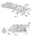
- FIG. 1is a schematic cross-sectional side view of a traditional liquid crystal display backlight
- FIG. 2is a schematic cross-sectional side view of one embodiment of an enhanced LCD backlight of the invention utilizing CCFL light sources with asymmetric particles contained within the light guide;
- FIG. 3is a perspective view of the embodiment of FIG. 2 ;
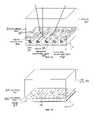
- FIG. 4is a perspective view of one embodiment of an enhanced LCD backlight of the invention utilizing LEDs with asymmetric particles contained within the light guide;
- FIG. 5is a perspective view of one embodiment of an enhanced LCD backlight of the invention utilizing LEDs with asymmetric particles of varying densities contained within the light guide;
- FIG. 6is an example of a side emitting LED from LUMILEDS Inc.
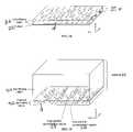
- FIG. 7is a perspective view of an LCD backlight utilizing side-emitting LEDs (Prior Art);
- FIG. 8is a perspective view of one embodiment of an enhanced LCD backlight of the invention utilizing side-emitting LEDs with asymmetric particles contained in a region optically coupled to the light guide;
- FIG. 9is a perspective view of one embodiment of an enhanced LCD backlight of the invention utilizing two CCFLs with asymmetric particles contained in a region optically coupled to the light guide;
- FIG. 10is a perspective view of one embodiment of an enhanced LCD backlight of the invention utilizing two CCFLs with asymmetric particles of varying densities contained in a region optically coupled to the light guide;
- FIG. 11is a perspective view of one embodiment of an enhanced LCD backlight of the invention utilizing two CCFLs with two regions containing asymmetric particles aligned with their axis crossed and optically coupled to the bottom of the light guide;
- FIG. 12is a perspective view of one embodiment of an enhanced LCD backlight of the invention utilizing two CCFLs with two regions containing asymmetric particles aligned with their axis crossed and optically coupled to the top of the light guide;
- FIG. 13is a perspective view of one embodiment of an enhanced LCD backlight of the invention utilizing two CCFLs with two regions containing asymmetric particles aligned with their axis crossed and optically coupled to the top and bottom of the light guide;
- FIG. 14is a perspective view of one embodiment of an enhanced LCD backlight of the invention with asymmetric particles contained within the tapered light guide and two CCFL light sources;
- FIG. 15is a perspective view of one embodiment of an enhanced LCD backlight of the invention utilizing two CCFLs with a light guide region composed of two regions containing asymmetric particles aligned with their axis crossed;
- FIG. 16is a perspective view of one embodiment of an enhanced LCD of the invention using the enhanced backlight of FIG. 9 ;
- FIG. 17is a perspective view of one embodiment of an enhanced LCD of the invention using the enhanced backlight of FIG. 9 and two crossed collimating films;
- FIG. 18is a perspective view of one embodiment of an enhanced LCD of the invention using the enhanced backlight of FIG. 9 and two crossed collimating films and an additional diffuser;
- FIG. 19is a perspective view of one embodiment of an enhanced LCD of the invention using the enhanced backlight of FIG. 9 , two crossed collimating films and a reflective polarizer;
- FIG. 20is a perspective view of one embodiment of an enhanced LCD of the invention using the enhanced backlight of FIG. 9 , two crossed collimating films with one of the collimating films containing asymmetric particles;
- FIG. 21is a perspective view of one embodiment of an enhanced LCD of the invention using an enhanced backlight with a high refractive index light guide and a low refractive index coating with crossed collimating films;
- FIG. 22is a perspective view of one embodiment of an enhanced backlight of the invention with a light guide positioned above cold cathode fluorescent lamps with varying concentration of dispersed phase particles;
- FIG. 23is a perspective view of one embodiment of a light guide used in the enhanced backlight of FIG. 9 ;
- FIG. 24is a perspective view of one embodiment of a light guide of the invention used with non-spherical particles in between the input and output surfaces of the light guide;
- FIG. 25is a perspective view of one embodiment of a light guide used in the enhanced backlight of FIG. 22 .
- “Speckle”includes scintillation or the optical interference pattern visible on a diffusing element.
- “Speckle Contrast”is defined herein as the ratio of the standard deviation of the intensity fluctuation to the mean intensity over the area of interest.
- Diffuse and “diffusing” as defined hereinincludes light scattering by reflection, refraction or diffraction from particles, surfaces, or layers or regions.
- Dispersed phaserefers to regions of material that are distinct from the surrounding material. They are confined regions having distinct boundaries of different optical or physical characteristics without regard to specific shapes and sizes.
- the particlewill typically scatter light if the optical properties such as refractive index is different from that of its surrounding material in at least one of the x, y, or z directions.
- the optical properties of the particle as described hereinmay be considered as independent of how it was made.
- a dispersed phasemay refer to the lower concentration of two immiscible blends that were extruded, or it may refer to glass fibers that were added to a material before extrusion to form dispersed phases (glass fibers) in a continuous phase matrix.
- micro-bodiesinclude particles, particulates, dispersed phases, phases within a matrix of material, gaseous bubbles within a material, voids, spheres, microspheres, hollow microspheres, fibers, etc.
- Polarizeras defined herein include absorbing or reflecting polarizers. These include dye and iodine based polarizers and reflective polarizers such as DBEF films from 3M. Linear or circular polarizers are also included. As used in these embodiments, it is commonly known that polarizers may be combined with waveplates or birefringent films in order to increase light recycling efficiency. For example, a quarter-wave film may be combined with a reflective polarizer to rotate the polarization state of the light such that more may pass through the polarizer.
- Optically coupledis defined herein as a condition wherein two regions or layers are coupled such that the intensity of light passing from one region to the other is not substantial reduced by Fresnel interfacial reflection losses due to differences in refractive indices between the regions.
- “Optically coupling” methodsinclude methods of coupling wherein the two regions coupled together have similar refractive indices or using an optical adhesive with a refractive index substantially near or in between the regions or layers. Examples of “Optically coupling” include lamination using an index-matched optical adhesive, coating a region or layer onto another region or layer, or hot lamination using applied pressure to join two or more layers or regions that have substantially close refractive indices. Thermal transfer is another method that can be used to optically couple two regions of material.
- Primary or “Prismatic sheet” or “Prismatic structure”is defined herein as a surface relief structure that refracts light toward a desired direction. This refraction can provide collimating properties to light passing through the film.
- the structurecan include arrays of elongated prism structures, micro-lens structures, and other surface relief structures known in the art.
- Light guideor “waveguide” refers to a region bounded by the condition that light rays traveling at an angle that is larger than the critical angle will reflect and remain within the region. In a light guide, the light will reflect or TIR (totally internally reflect) if it the angle ( ⁇ ) does not satisfy the condition
- n 1is the refractive index of the medium inside the light guide and n 2 is the refractive index of the medium outside the light guide.
- n 2is air with a refractive index of n ⁇ 1, however, high and low refractive index materials can be used to achieve light guide regions.
- the light guidemay comprise reflective components such as reflective films, aluminized coatings, surface relief features, and other components that can re-direct or reflect light.
- the light guidemay also contain non-scattering regions.
- Lightcan be incident on a light guide region from the sides or below and surface relief features or light scattering particles, phases or elements within the region can direct light into larger angles such that it totally internally reflects, or into smaller angles such that the light escapes the light guide.
- the light guidedoes not need to be optically coupled to all of its components to be considered as a light guide.
- a regioncan be functional as a waveguide for the purposes illustrated herein, as long as the thickness is larger than the wavelength of light of interest.
- a light guidemay be a 5 micron region with 2 micron ⁇ 3 micron ellipsoidal dispersed particles, or it may be a 3 millimeter diffuser plate with 2.5 micron ⁇ 70 micron dispersed phase particles.
- the “gain” of a light scattering elementis the ratio of the maximum luminance of an illuminated light transmitting material in a given direction relative to the luminance of a theoretically perfect diffuser in the same direction.
- a known amount of lightis directed to the sheet, and the maximum luminance is measured using a standard luminance meter. The maximum luminance of light measured is then compared to a theoretically “perfect” diffusive material.
- the gain for an imperfect diffuseris the value of the maximum luminance (ML) divided by the value of the luminance of the theoretically perfect diffuser.
- MLmaximum luminance
- the gainwill be maximum (ML) and larger than 1 for a given viewing direction (typically measured orthogonal to the plane of the diffuser).
- a high gain screenwill typically be brighter when viewed orthogonal to the plane than at other angles. Because the light transmitted by the material can never be more than the amount of light supplied, less light must be transmitted at angles other than the angle of maximum luminance.
- Angle of viewis a measurement of illumination for all angles relative to two perpendicular axes (i.e., x and y) in the plane of the material.
- the angle of viewis measured by applying a “full-width at half maximum” approach, a “full-width at one-third maximum” approach, and a “full-width at one-tenth maximum approach.”
- the AOV at full-width at half maximum( ⁇ (1 ⁇ 2)) is calculated from sum of the absolute value of the angles (measured from an orthogonal to the plane of the material) at which the measured luminance is one-half the maximum luminance measured and noted.
- the AOV ⁇ (1 ⁇ 2) in the horizontal direction for the screenwould be 70°.
- the AOV at full-width at one-third maximum ( ⁇ (1 ⁇ 3)) and the AOV at full-width at one-tenth maximum ( ⁇ ( 1/10))are calculated similarly, except that they are calculated from the angles at which the luminance is one-third and one-tenth of the maximum luminance respectively.
- the “asymmetry ratio”is the horizontal AOV ⁇ (1 ⁇ 2) divided by the vertical AOV ⁇ (1 ⁇ 2), and thus is a measure of the degree of asymmetry between the horizontal luminance and the vertical luminance of the diffuser.
- Planarizationrefers to the adding of a material to a surface relief pattern or structure to increase the flatness of the surface. This can be measured by the surface roughness. An increased flatness (lower surface roughness) can promote better adhesion and in some cases have improved optical, mechanical or physical performance.
- a “spherical” or “symmetric” particleincludes those substantially resembling a sphere.
- a spherical particlemay contain surface incongruities and irregularities but has a generally circular cross-section in substantially all directions.
- a “spheroid”is a type of ellipsoid wherein two of the 3 axes are equal.
- An “asymmetric” particleis referred to here as an “ellipsoidal” particle wherein each of the three axis can be a different length.
- ellipsoidal particlesresemble squashed or stretched spheres.
- Non-spherical” particlesinclude ellipsoidal particles and other particles defined by shapes that do resemble a sphere such as those that not have constant radii. For example, a non-spherical particle may have finger-like extensions within one plane (amoeba-like) and substantially planar in a perpendicular plane.
- the present inventionprovides an improved light guide with inherently more flexibility for display system designers and higher optical efficiency.
- a light guide containing substantially aligned asymmetric particlesBy using a light guide containing substantially aligned asymmetric particles, more efficient control of the light scattering can be achieved.
- One or more regions containing asymmetric particlesmay be used and the particle sizes may vary between 2 and 100 microns in the smaller dimension.
- the light scattering regionsmay be substantially orthogonal in their axis of alignment.
- one or more asymmetrically scattering filmscan be used in combination with a backlight light guide and a reflector to produce an efficient backlight system.
- the light guidesmay be manufactured by embossing, stamping, or compression molding a light guide in a suitable light guide material containing asymmetric particles substantially aligned in one direction.
- the light scattering light guide or non-scattering light guidemay be used with one or more light sources, collimating films or symmetric or asymmetric scattering films to produce an efficient backlight that can be combined with a liquid crystal display or other transmissive display.
- the efficiency of the recycling of light by using reflective polarizerscan also be increased.
- the non-spherical particlescan be added to the matrix material during processing or they can be created during manufacturing.
- particles not substantially asymmetric in shapemay be stretched along an axis after coating or during or after an extruding process such that they become asymmetric in shape.
- Other methods for achieving a single region of non-spherical particles in a regionare disclosed in U.S. Pat. No. 5,932,342, the text of which is incorporated herein by reference.
- multiple layers or multi-region methodssuch as co-extrusion, optical lamination, optical coupling, thermal bonding, multiple regions containing light scattering particles can be combined into a single light scattering element.
- the degree of stretchingcan control the asymmetry and thus achieve a desired level of asymmetric light scattering.
- the asymmetric particlesmay have a large variation in size depending on the desired level of asymmetry.
- Methods including co-extrusion, laminating, thermal bonding, etc.can be used to achieve multiple regions containing dispersed phases with improved optical performance.
- the dispersed phase materialmay blended with the continuous phase material in a compounding step, a tumbling mixer, in a solvent blending process, or within an extruder.
- the asymmetric particles in the light guideare obtained by reducing particles in size in the x, y or other directions by stretching a film after or during extrusion.
- the particleshave a refractive index n p1 different from the host matrix material refractive index n h1 defined by at least one of
- the differential refractive index ( ⁇ n MP )defined as the absolute value of the difference between the index of refraction of the matrix (n M1 ) and the index of refraction of the particles (n P1 ), or
- ,may be from about 0.005 to about 0.2, and preferably is from about 0.007 to about 0.1 in the x, y, or z directions.
- non-spherical particlesWhen more than one type of non-spherical particles are used within a light diffusing sheet, they may have a refractive index n p2 in the x, y, or z direction that is the same or different to that of the continuous phase or the dispersed phase refractive index.
- the asymmetric featurestypically are all oriented with their major axes substantially in one direction in the plane of the surface of the material.
- the particlesare made from a material which is capable of being deformed at a processing temperature in order to create their non-spherical shape by stretching.
- the shapemay resemble a non-spherical ellipsoid or shapes that have non-constant radii in the x, y, or z direction may also be formed.
- the domainsmay appear randomly shaped in one plane (amoeba-like) and substantially planar in a perpendicular plane.
- the volume density of the particle, the average size and shape, and the index of refraction in the x, y, and z directionsmay be optimized to control desired properties of the light guide.
- the average dimension of a dispersed domain or particle in the x, y, or z direction in the matrixmay be from about 1 ⁇ m to about 30 ⁇ m, preferably from about 2 ⁇ m to about 15 ⁇ m, and most preferably from about 2 ⁇ m to about 5 ⁇ m in the minor dimension.
- the average dimension of a dispersed domain or particle in the x, y, or z direction in the matrixmay be from about 2 ⁇ m to about 2 cm, preferably from about 5 ⁇ m to about 1 cm, and most preferably from about 10 ⁇ m to about 500 ⁇ m in the major dimension.
- the differential refractive index ( ⁇ n ME )is defined as the absolute value of the difference between the index of refraction of the matrix (n M ) and the index of refraction of the ellipsoidal particles (n E ), or
- ,may be from about 0.005 to about 0.2, and preferably is from about 0.007 to about 0.1 in the x, y, or z direction.
- Suitable materials for the particlesinclude acrylics such as polymethylacrylates; polystyrenes; polyethylenes; polypropylenes; organic acid cellulose esters such as cellulose acetate butyrates, cellulose acetates, and cellulose acetate propionates; polycarbonates; or silicones.
- the particlesmay also contain coatings of higher or lower refractive index materials, or they may be hollow materials containing a gas mixture such as air.
- polyethylenemay be used.
- transmissive micro-bodiesinclude those that are not deformed during the extrusion or manufacturing process. These include spherical or non-spherical materials that have fibrous, plate-like or other orientable shapes. These include inorganic fibrous material, glass fibers, mica, silica, cross-linked polymers, plate-like materials, fibrous polymer materials with high melting points or high glass transition temperatures.
- the micro-bodiesmay be aligned during the manufacturing process, such as alignment due to stretching or extruding the region containing the dispersed micro-bodies.
- the light guidemay also contain a surface relief structure on one or more surfaces of the material.
- the asymmetric surface relief structurecan be manufactured by techniques as described above, e.g., embossing.
- the surface reliefdesirably contains asymmetrically shaped features predominantly aligned in the horizontal or vertical directions such that they refract, diffract, scatter, diffuse the incident light in the horizontal or vertical directions.
- the surface relief structure of the light guidemay help reflect, diffract, refract, or scatter light into the light guide.
- the surface relief structure of the light guidemay collimate light (bring it toward smaller angles towards the display normal for example).
- the surface relief structure lightcan be collimated.
- the asymmetric microbodiesshould be oriented horizontally (i.e., perpendicular to the lenticules) so the scattering is substantially in the vertical direction (i.e., parallel to the lenticules).
- the collimated lightis focused through the non-spherical particles with the light scattering only in the vertical direction.
- the alignment of the asymmetric micro-bodiescan also vary. By aligning the particles with respect to the prismatic structure at angles other than parallel or perpendicular, other asymmetric viewing angles can be achieved.
- the asymmetric micro-bodieswill inevitably cause some scattering in the minor axis. This may be designed to be very small, or significant.
- the scattering in the minor axisis chosen to be just sufficient to diffuse the specular component of the light source in the plane perpendicular to major axis of the prismatic structure.
- Multiple-element diffusers in accordance with the inventionare desirably optically coupled to one another, i.e., so the intensity of light passing from one region to the other is not substantially reduced due to Fresnel interfacial reflection losses due to differences in refractive indices between the regions.
- Optical coupling methodsinclude joining two regions having similar refractive indices, or by using an optical adhesive with a refractive index substantially near or in between the elements or layers.
- Particles that are significantly smaller than the wavelength of lightmay be added to alter the effective refractive index.
- the size of the particlesare less than 1/10 th the wavelength of light. In a preferred embodiment, the size of the particles are less than 1/20 th the wavelength of light of interest such that significant additional scattering (forward or backward) does not take place.
- These particlesmay be symmetric, asymmetric, or random in shape.
- very fine particles of titanium dioxidemay be added to a material to increase the effective refractive index of the material. The effective refractive index change can adjust the scattering properties of the material, refractive properties, and the interfacial reflections.
- the diffusers of the inventionmay also include an optional hardcoat to increase the stability of the element, and/or an optional anti-reflective coating.
- the hardcoatmay be any light-transmissive support layer, such as a siloxane-based polymer layer.
- FIG. 1shows a prior art light guide section 10 in a backlight, where white dots 12 scatter the light in a Lambertian-like manner, thus sending a significant amount of light toward the light source 14 (i.e., back scattering). A large percentage of this light is lost (i.e., it escapes the light guide and is therefore unusable) when it reaches the edge 16 of the light guide 10 where the light was coupled in originally. As shown in FIG. 1 , light reflecting off of the white dots 12 is scattered in the ⁇ y and ⁇ x and +z directions. This is inadequate control over the scattering, and light sent to wide angles is lost.
- FIG. 2illustrates one embodiment of an enhanced LCD backlight of this invention, wherein light from a CCFL 14 is directed into the edge 16 of a light guide 10 containing asymmetric particles 18 .
- This light guide 10will have less backscatter and more light will be coupled out of the light guide 10 in the forward direction (+z direction).
- the asymmetric particles 18will preferentially scatter light in a forward direction (+x direction) and out of the light guide 10 (+z direction).
- the light guide 10may be formed by casting or forming a sufficiently thick polymer material 20 containing asymmetric particles 18 .
- a further embodiment of an enhanced backlightmay include additional light diffusing films or regions and collimating sheets. Birefringent films and reflective polarizers may also be used to increase backlight efficiency.
- FIG. 3illustrates a perspective view of the backlight light guide 10 shown in FIG. 2 .
- the asymmetric particles 18 in the light guide 10predominantly scatter light from the CCFL 14 that is traveling in the +x direction into the ⁇ z directions.
- the ⁇ z direction scatteringwill reach a reflector and be re-directed in the +z direction.
- linear CCFLs 14are used, very little scattering is needed in the y direction, because the lamp 14 is essentially a linear extended source in the y direction.
- an asymmetric scattering regionis more efficient, because it predominantly scatters light in the ⁇ z directions and very little, if any, in the ⁇ y directions.
- FIG. 4illustrates an embodiment of this invention of an enhanced LCD backlight wherein LEDs 14 are used with an asymmetrically scattering light guide 10 .
- LEDs 14are used to couple light in from the edge of the light guide 10 more control over the light can be achieved due to the ability to substantially collimate light from the LEDs 14 using collimating lenses 24 .
- the directionality of the light from LEDscan be more tightly controlled, relative to the CCFLs.
- the angular distribution of lightcan be better controlled by using an asymmetric scattering region.
- the light from the LEDs 14is traveling substantially only in the +x direction with very little divergence in the ⁇ y directions.
- the asymmetric particles 18are aligned such that they will diffuse the light predominantly out of the light guide 10 .
- FIG. 5illustrates a further embodiment of this invention of an enhanced LCD backlight wherein the density of particles 18 varies throughout the length of the light guide 10 .
- a backlight light guide 10containing uniform particle densities throughout the light guide 10 and a high concentration of particles 18 , the light intensity uniformity can be poor. With a uniform high density of particles 18 more light is scattered out of the light guide 10 closer to the light source 14 .
- the non-uniformityis controlled by the size and spacing of the white dots with typically more printed white area further from the light source. By varying the density (concentration) of asymmetric particles 18 in different regions of the light guide 10 a more uniform output can be achieved. As shown in FIG.
- the optimum variation in particle densitycould change from low to high to low density regions.
- Other density patterns or variationsare envisioned that can provide a uniform light output intensity for a specific light source arrangement.
- the variation in particle densitymay be controlled in the manufacturing process of the asymmetric light guide 10 .
- an extruder for a filmcan be designed to accept feeds from different mixtures containing different concentrations of particles within the same host matrix.
- This film or sheetcould be extruded sufficiently thick to function as a light guide for a specific light source or multiple sheets or film layers could be combined.
- the thicknessis also reduced as shown in FIG. 5 because of the wedge shape of the light guide 10 . In this manner, the wedge shape helps reflect light from the surfaces or a reflector 22 such that it can escape the total internal reflection condition and be a more uniform backlight.
- LED based backlightscan also use the side emitting LEDs 14 such as those manufactured by LUMILEDS ( FIG. 6 ). These side emitting LEDs 14 can be used in the central portion of a light guide such that the LEDs 14 are in a row and the light output totally internally reflects in the light guide 10 from the center line outwards as shown in FIG. 7 (Prior Art). As shown in FIG. 7 , the light from the LEDs 14 enters through the hole in the light guide 10 and is totally internally reflected within the light guide 10 . If one were to use printed white dots or an HSOT light guide 10 , the light would scatter into undesirable angles and the system would be less efficient.
- the line configuration of the LEDs 14provides light along the ⁇ y directions. A symmetric diffuser placed on top of the light guide 10 of FIG. 4 or an HSOT would scatter light unnecessarily in the ⁇ y directions.
- Asymmetric scattering regionsallow additional control of the scattered light.
- the scattering regionsmay be located within the light guide region, or alternatively, the asymmetric scattering regions may be located above or below a substantially transparent light guide region.
- the scattering regionsmay become part of the light guide. In other words, the light may scatter in the scattering regions and a portion of this light may be totally internally reflected at an air-scattering region interface.
- FIG. 8illustrates another embodiment of this invention wherein a light scattering film 30 is optically coupled to a substantially non-scattering light guide 10 with the scattering particles 18 in the film 30 arranged parallel to a line of LEDs 14 located within the planar region of the light guide 10 .
- a light scattering film 30is optically coupled to a substantially non-scattering light guide 10 with the scattering particles 18 in the film 30 arranged parallel to a line of LEDs 14 located within the planar region of the light guide 10 .
- the light from the LEDs 14does not need to be substantially scattered in the ⁇ y directions.
- the reflector 22 beneath the light guide 14will re-direct light in the ⁇ z direction to the +z direction out of the light guide 10 .
- More than one light scattering film 30 or region with the same or different alignment axismay be used to achieve a desired angular profile of light output.
- FIG. 9illustrates an embodiment of this invention wherein a substantially planar asymmetric light scattering region 32 is located on the underside of a light guide 10 with a reflector 22 beneath.
- Light from two opposite ends of the light guide 10enter the edge from two CCFL lamps 14 .
- a portion of the light that reaches the asymmetric diffusive region 32scatters in the ⁇ z directions. There is very little scatter in the ⁇ y directions.
- the light that does not scatterreaches the reflector 22 and either scatters on the way back through the region 32 or is directed through total internal reflection to another region of the scattering film. As a result, less light is scattered back towards the edges or sides and more is directed out of the light guide 10 in the +z direction.
- FIG. 10illustrates a further embodiment of an enhanced backlight wherein the density of asymmetric particles 18 varies related to the distance from the light sources 14 .
- the regions 26 closer to the CCFLs 14contain a lower density of asymmetric light scattering particles 18 relative to the central portion 28 . This creates a more uniform light output with the scattering effects.
- the light guide 10may also be tapered and the backlight can contain additional symmetric or asymmetric diffusers, reflective polarizers, or collimating films between the light guide and the polarizer of the liquid crystal cell.
- FIG. 11shows another embodiment of this invention of an enhanced LCD backlight light guide 10 with two asymmetric scattering regions 32 and 34 aligned orthogonally between a reflective surface 22 and a light guide 10 .
- the light from the CCFL 14 aligned in the y directionwill reach the y-aligned asymmetric region 32 and most of the light will scatter in the ⁇ z directions and not be scattered unnecessarily in the x direction.
- the light from the CCFL 14 aligned in the x directionwill substantially pass through the y-aligned asymmetric region 32 and pass on to the x-aligned asymmetric region 34 . This light will then be scattered predominantly in the ⁇ z directions without having been scattered unnecessarily in the y direction.
- the light scattering regions 32 and 34are films located beneath the light guide 10 .
- the density, particle asymmetry and refractive index difference, and thickness of the two orthogonal scattering regions 32 and 34control the horizontal and vertical light scattering profile (thus viewing zones). These parameters can be adjusted individually for either layer to control the light profile.
- the light scattering regions 32 and 34could be located in separated (spaced apart) regions to create a multi-phase scattering region that will reduce the speckle contrast of the display.
- Asymmetric and symmetric particles 18may be located within the same region of the light guide 10 .
- the axis of the asymmetric scattering regions 32 and 34may be aligned at an angle theta with respect to each other. As shown, two CCFLs 14 are used. One, or more than two CCFLs or LEDs 14 may also be used in this configuration.
- FIG. 12shows another embodiment of an enhanced LCD backlight wherein two asymmetrically scattering regions 32 and 34 aligned at an angle with respect to each other are place between a light guide 10 and the polarizer optically coupled to a liquid crystal cell.
- the scattering axesare perpendicular to each other.
- the polarizer, liquid crystal cell, and other optical filmsare not shown for clarity.
- the light from the each of the CCFLs 14scatters similar to that in FIG. 11 .
- FIG. 13An additional embodiment of an enhanced LCD backlight is shown in FIG. 13 .
- This configurationis similar to the one in FIG. 12 except that one of asymmetric light scattering regions 34 is located beneath the light guide 10 with the other region 32 located above the light guide 10 .
- LLDs 14may be used instead of CCFLs 14 in this configuration. By spacing apart the scattering regions 32 and 34 with the light guide 10 , the speckle contrast can be reduced.
- FIG. 14shows another embodiment of this invention of an enhanced backlight light guide wherein a light guide 10 that is tapered from both ends contains asymmetric particles 18 that are substantially aligned in the y direction.
- the taperingcauses more light to be coupled out of the light guide 10 toward the center, giving a more uniform light distribution.
- the tapering of the light guide 10could also be used with LEDs 14 .
- the taperingcould also be in the y direction as well as the x direction.
- FIG. 15illustrates a further embodiment of this invention wherein the light guide is composed of two asymmetric scattering regions 32 and 34 .
- the lightis scattered similar to the embodiment illustrated in FIG. 11 except that the light is totally internally reflected within one or more of the light scattering regions 32 and 34 .
- the light scattering regions 32 and 34could be constructed of sufficient thickness such that the light from the light sources 14 (LEDs, CCFL, etc) could be coupled into the scattering regions 32 and 34 .
- the horizontal and vertical scatteringcan be easily controlled.
- the parameters of the scattering region(s) 32 and 34can be controlled to create a sufficiently uniform brightness across the backlight.
- the orthogonal light scattering particles 18may be combined within the same region that also functions as a light guide.
- FIG. 16illustrates a further embodiment of this invention of an enhanced liquid crystal display wherein the light guide 10 of FIG. 9 is combined with two polarizers 36 and liquid crystal cell 38 (which contains glass substrates, spacers, alignment regions, liquid crystal material and other materials known to those in the industry, not shown).
- collimating filmsmay not be needed to achieve a liquid crystal display with a desired viewing angle.
- the light from the LCDexits substantially diffused in the ⁇ x directions and much less in the ⁇ y directions.
- This LCDwould have a wide viewing angle in the horizontal direction and a small vertical viewing angle and the resulting brightness would be much higher than that of a comparable backlight with a wide horizontal and vertical viewing angle.
- FIG. 17illustrates a further embodiment of this invention of an enhanced LCD wherein two substantially crossed collimating films 40 and 42 such as Brightness Enhancement Film from 3M or RCF film manufactured by REFLEXITE are added to the configuration of FIG. 16 .
- Collimating films 40 and 42can direct at least a portion of the light from wide angles to angles closer to the normal (+z direction). This could be used to further increase the on-axis brightness of the LCD relative to that of FIG. 16 .
- the light scattering region 32 parameterscan be adjusted in conjunction with the collimating films 40 and 42 to achieve the desired angular light profile output and uniformity.
- the collimating films 40 and 42may contain prismatic structures 44 with parameters that vary across the film. The height of the prismatic structures 44 can vary lengthwise along the prisms 44 .
- the pitch of the prisms 44may be non-constant.
- the pitchcould be randomly chosen or it could be pre-determined to be a non-regular spacing.
- the apex angle of the prisms 44could also vary with a regular or irregular pitch.
- the pitch of the prisms 44could also vary lengthwise along the prisms.
- the prisms 44could extend at an angle relative to the edge of the film.
- FIG. 18illustrates a further embodiment of this invention of an enhanced LCD backlight wherein a diffuser 46 is added to the light guide configuration of FIG. 17 .
- a symmetric or asymmetric diffuser 46is added between the light guide 10 and the collimating films 40 and 42 .
- the diffuser 46can reduce the appearance of speckle from the backlight. This is more critical when LEDs are used as light sources 14 versus CCFLs.
- the additional diffuser 46will also reduce the appearance of non-uniformities in the backlight intensity variations.
- a diffusive surface relief structuremay be used beneath the collimating film structures 40 and 42 as is the case with the RCF film.
- FIG. 19illustrates a further embodiment of this invention of an enhanced LCD backlight wherein a reflective polarizer 48 is positioned above the top collimating film 40 and the liquid crystal cell 38 and polarizers 36 .
- a reflective polarizer 48is often used with LCD backlights to recycle the light such that more can be used.
- the reflective polarizer 48is aligned to transmit light of the desired polarization (S-wave, for example) and reflect P-wave polarized light. By passing back through the diffusers after reflection and scattering the polarization of this light can be rotated such that upon reaching the reflective polarizer 48 for a second time, more can pass through.
- S-wavedesired polarization
- the polarizationcan be rotated due to stress birefringence of one or more of the optical films or light guides or the polarization can be de-polarized be the scattering off the white dots.
- the asymmetric scattering regions 32can be designed to have a specific birefringence such that the light is rotated efficiently such that a higher percentage of the light can pass back through the reflective polarizer 48 on the second pass. Additionally, because the control of the light scattering is more efficient with the volumetric asymmetric scattering regions 32 , the recycled light also scatters more efficiently, thus more of it passes through the reflective polarizer 48 on the second or later passes and the display is brighter.
- FIG. 20illustrates a further embodiment of this invention of an enhanced LCD backlight wherein one of the asymmetric scattering regions is located within the collimating film 42 .
- the asymmetrically scattering collimating film 42can contain asymmetrically shaped light scattering particles 18 within the substrate 50 , the prismatic structures 44 , or in both regions. One or more of these regions 50 and 44 may contain substantially symmetric particles 18 .
- the details of such asymmetric collimating films 42are further described in U.S. Patent Application No. 60/605,956, the entire contents of which are incorporated herein by reference.
- the embodiments described for an enhanced light diffusing sheetcan be used with the enhanced LCD backlight invention described herein.
- FIG. 21illustrates a further embodiment of this invention of an enhanced LCD backlight wherein the light guide 10 is made using a high refractive index material.
- a high refractive index materialBy optically coating a low refractive index region 52 on the top surface of the light guide 10 , an additional film such as a collimating film 42 may be optically coupled to the surface. This can reduce the number of air gaps required and simplify the assembly process.
- the high and low refractive index materialscan still enable a light guide that will allow the light to reflect multiple times to create uniformity across the backlight.
- the low refractive index materialcould be an aerogel, sol-gel or plastic with microscopic pores. It may also be an adhesive such that it can also function to adhere a film such as the collimating film 42 to the light guide 10 .
- the high refractive index materialcould be commonly known high refractive index polymers or other material such as Nitto Denko's high-refractive index thermosetting polymer capable of reaching a refractive index of 1.76 (See Nitto Deniko Press Release, 11 Nov. 2003, at http://www.nitto.com/company/release/03 — 11 — 11/index.html). Additional diffusers, collimating films 40 , and polarizers 36 may be used to produce the desired light output. CCFLs or LEDs 14 may be used in conjunction with the high refractive index light guide 10 .
- a low refractive index planarization layeris used above the collimating film 42 so that an additional collimating film 40 may be optically coupled to the first collimating film 42 and retain its light collimating characteristics.
- this second collimating film 40could have a planarization layer, thus allowing other films such as a reflective polarizer to be optically coupled to it, further reducing system thickness and difficulties associated with required air gaps.
- FIG. 22illustrates an embodiment of this invention wherein a light guide 10 containing a higher concentration of dispersed particles 18 directly above fluorescent lamps 14 in a backlight can improve the luminance uniformity of the backlight.
- the illuminance on the light scattering region 32 of the light guide 10 directly above the lamps 14is higher because it is closer to the light sources 14 and occupies a larger angular extent of the radiance in that region 32 .
- the luminance from the light guide 10would be higher in the regions near the light sources 14 .
- an asymmetric diffusing region 32the luminance uniformity across the light guide 10 would still be improved, although it is unlikely to be sufficiently uniform for a thin diffuser.
- the light scattering region 32 of FIG. 22contains regions with higher concentration of asymmetric particles 18 in the regions closer to the light source.
- the regions with the high illuminancespread the light into larger angles (in the x-z plane).
- the concentrationis reduced, allowing the light to pass through the light scattering region 32 and contribute to illuminance averaging by combining with that of another light source.
- the uniformitycan be further increased by adding a second light diffusing region within the light guide 10 or between the light guide 10 and the display.
- a second light diffusing regionwill reduce the speckle contrast of the display and increase the uniformity and display contrast.
- a reduction in thickness in regions between the light sources 14can achieve a similar affect.
- both the concentration and the thicknesscan be reduced as illustrated in FIG. 5 .
- FIG. 23illustrates an embodiment of this invention wherein a light guide 10 comprises a light scattering region 32 and a non-scattering region 54 .
- the scattering region 32contains non-spherical dispersed phase domains 18 and can be used to create the uniform luminance backlight of FIG. 9 .
- FIG. 24illustrates an embodiment of this invention wherein a light guide 10 comprises a light scattering region 32 and a reflector 22 that can be used to scatter the incident light into angles that do not satisfy the total internal reflection condition at the output boundary.
- the scattering region 32contains non-spherical dispersed phase domains 18 .
- FIG. 25illustrates an embodiment of this invention wherein a light guide 10 comprises a light scattering region 32 and a non-scattering region 54 .
- the scattering region 32contains non-spherical dispersed phase domains 18 with a spatially varying concentration and can be used to create the uniform luminance backlight of FIG. 22 .
- Additional diffusive layers or regionsmay be added to the top of the light guide or bottom of the light guide.
- the asymmetric scattering regions described hereinmay be located at the top or bottom of the light guide and may be aligned at an angle with respect to an edge.
- the reflective filmsmay be reflective polarizers.
- Light from LEDsmay be directed into one or more of the edges or surfaces of a light guide.
- Forward directing LEDsmay be used behind an LCD panel wherein the asymmetric diffuse layers or regions will smooth out the intensity “hot-spots” where needed. For example, if three lines of forward directing LEDs are located behind an LCD, an asymmetric diffuser which will diffuse the light more in a direction perpendicular to the direction of the lines will more efficiently create a uniform intensity distribution and result in higher forward light output.
- White LEDs or LEDs of multiple colors such as red, green, and bluemay be used.
- the size, shape, concentration, and orientation of the asymmetric particlesmay be controlled to produce the desired intensity variation, and direction of light output.
- a light focusing patternis embossed into the exiting surface of the light guide.
- this structurewould be that of a saw tooth nature, or an array of prisms or lens-like features such as is known in the industry.
- optical filmsmay be used in combination with the asymmetric diffusing region and light guide.
- Such optical filmsas prismatic films, polarizers, reflective polarizers, waveplates etc. may be used to increase brightness, efficiency or performance of the LCD.
- Tapered or un-tapered light guidesmay be used with a light guide that contains asymmetric particles or a substantially non-diffusing light guide with an asymmetric diffusing region on the top or bottom of the substrate.
- the tapermay be a constant angle or it may be a curved shape to produce a desired light output profile.
- the backlightmay be used with liquid crystal displays. It can also be appreciated that the backlight of the invention can enhance the performance of other types of displays such as backlit signs, electrophoretic displays, LCD TV's, LCD monitors, and other active or passive transmissive displays known to those in the display industry.
- An enhanced LCD backlightin accordance with the present invention, can be produced as described in FIG. 3 , that is designed to have increased optical efficiency and therefore increased brightness relative to existing backlights. This is possible because the volumetric asymmetric diffusive region within the light guide allows for better control over the light scattering.
- Light from two CCFL lampsis coupled into the light guide.
- the light guidecontains light scattering particles in a host matrix material.
- the particle chosenmay be a polystyrene bead of diameter 5 ⁇ m dispersed at concentrations up to 10% by volume in a host matrix of acrylic. Other choices of particles and host matrix may provide equivalent performance.
- Asymmetry and alignment of the asymmetrycan be created by stretching or extrusion processes.
- the asymmetrically diffusing light guidecan be created by extruding, casting or coating, the mixture containing the particles.
- the light guidemay be 2.5 mm in thickness and this may be achieved by optically coupling more than one layer or region containing asymmetric particles.
- One or more collimating filmssuch as 3M's Brightness Enhancement Film can be added to the top of the light guide to direct more light toward the on-axis direction.
- a reflective polarizersuch as 3M's DBEF film can be added to increase the brightness through polarized light recycling. To further reduce speckle, scattering regions can be separated by a non-scattering region.
- An enhanced LCD backlightin accordance with the present invention, can be produced as described in FIG. 11 , that is designed to have increased optical efficiency and therefore increased brightness relative to existing backlights. This is possible because the volumetric asymmetric diffusive region below the light guide allows for better control over the light scattering.
- Two crossed asymmetric light scattering regionsare optically coupled to the non-scattering light guide. Light from two CCFL lamps is coupled into the light guide.
- the asymmetric light scattering regionscontain asymmetric particles in a host matrix material. The regions may be created by creating a mixture consisting of polystyrene bead particles of diameter 5 ⁇ m dispersed at concentrations up to 10% by volume in a host matrix of acrylic. Other choices of particles and host matrix may provide equivalent performance.
- the asymmetrically diffusing regionscan be created by extruding, casting or coating, the mixture containing the particles. These regions or films may be optically coupled to the light guide film in a crossed configuration. Light scattering regions with different scattering properties may be used to give an asymmetric angle of view when coupled to an LCD.
- One or more collimating filmssuch as 3M's Brightness Enhancement Film can be added to the top of the light guide to direct more light toward the on-axis direction.
- a reflective polarizersuch as 3M's DBEF film can be added to increase the brightness through polarized light recycling.
- the scattering regionscan be separated by a non-scattering region.
- An enhanced LCD backlightin accordance with the present invention, can be produced as described in FIG. 8 , that is designed to have increased optical efficiency and therefore increased brightness relative to existing backlights. This is possible because the volumetric asymmetric diffusive region within the light guide allows for better control over the light scattering.
- the light guidecontains asymmetric light scattering particles aligned parallel to the line of LEDs.
- the asymmetric light scattering light guidecontain asymmetric particles in a host matrix material.
- the regionsmay be created by creating a mixture consisting of polystyrene bead particles of diameter 5 ⁇ m dispersed at concentrations up to 10% by volume in a host matrix of acrylic.
- the asymmetrically diffusing light guidecan be created by extruding, casting or coating, the mixture containing the particles.
- concentration of the light scattering particlescan be chosen to provide the optimum uniformity of light output from the light guide.
- a reflectoris optically coupled to the underside of the light guide as illustrated in FIG. 8 .
- One or more collimating filmssuch as 3M's Brightness Enhancement Film can be added to the top of the light guide to direct more light toward the on-axis direction.
- a reflective polarizersuch as 3M's DBEF film can be added to increase the brightness through polarized light recycling.
- the scattering regionscan be separated by a non-scattering region.
Landscapes
- Physics & Mathematics (AREA)
- General Physics & Mathematics (AREA)
- Optics & Photonics (AREA)
- Planar Illumination Modules (AREA)
- Optical Elements Other Than Lenses (AREA)
Abstract
Description
where n1is the refractive index of the medium inside the light guide and n2is the refractive index of the medium outside the light guide. Typically, n2is air with a refractive index of n≈1, however, high and low refractive index materials can be used to achieve light guide regions. The light guide may comprise reflective components such as reflective films, aluminized coatings, surface relief features, and other components that can re-direct or reflect light. The light guide may also contain non-scattering regions. Light can be incident on a light guide region from the sides or below and surface relief features or light scattering particles, phases or elements within the region can direct light into larger angles such that it totally internally reflects, or into smaller angles such that the light escapes the light guide. The light guide does not need to be optically coupled to all of its components to be considered as a light guide. A region can be functional as a waveguide for the purposes illustrated herein, as long as the thickness is larger than the wavelength of light of interest. For example, a light guide may be a 5 micron region with 2 micron×3 micron ellipsoidal dispersed particles, or it may be a 3 millimeter diffuser plate with 2.5 micron×70 micron dispersed phase particles.
- 1. Light sources: CCFL; LED; OLED; electroluminescent material; laser diode; fluorescent bulb; substantially planar fluorescent bulb; halogen bulb; incandescent bulb; metal halide bulb;
- 2. Light source color: Red; green; blue; white; cyan; magenta; yellow;
- 3. Light source location: one edge of the light guide; more than one edge of a light guide; opposite side of the light guide than the liquid crystal cell; within the light guide;
- 4. Spacing between light scattering regions, polarizers, light guides: air gap; optically coupled.
- 5. Scattering region:
- a. Scattering region location: above the light guide; below the light guide; within the light guide; above collimating film(s); below collimating film(s); in between collimating films; within the prismatic structures; in the substrate of the prismatic structures; in both the prismatic structures and in the substrate; in regions of the substrate or prismatic structures wherein the regions are separated by a non-diffusing region (multi-phase).
- b. Diffusing particle shapes: Symmetric; or asymmetric particles; or a combination of both.
- c. Diffusing particles refractive index: average refractive index npwherein |np−nm|>0.001; refractive index npxand npy, in the x and y directions respectively, wherein |npx−nm|>0.001; |npy−nm|>0.001; or |npy−nm|>0.001 and |npx−nm|>0.001.
- d. Diffusing particles density: substantially constant; varying along the y axis; varying along the x axis; varying along the z axis;
- e. Asymmetric particle alignment: substantially parallel to the prisms; substantially perpendicular to the prisms; or at an angle beta with respect to the prisms.
- 6. Prismatic Collimating films:
- a. Prism Pitch: Constant; non-constant (irregular); random.
- b. Prism Orientation: At an angle, phi, with respect to a predetermined edge; or at an angle phi2, wherein phi2 varies across the length of the prisms.
- c. Prism height: Constant; varying lengthwise across the length of the prisms; varying from one prism to another.
- d. Prism Apex angle: At a constant angle, alpha; or at an angle alpha2, wherein alpha2 varies across the length of the prisms; or at an angle alpha3, wherein alpha3 can vary from one prismatic structure to the next
- e. Prism structure refractive index: nm, with the region in optical contact with the prism structure having a refractive index n1wherein nm>n1.
- f. Surface structure on sheet face opposite prism face: planar; prismatic; microlens array; surface relief structure providing pre-determined angular scattering (included ruled structure, holographic diffuser); any combination of the above structures.
- 7. Reflector type: aluminized film; aluminized light guide; multilayer film (such as 3M's ESR film); reflective polarizer; transflective; micro-voided film; white scattering paint or coating; a region containing white scattering dots.
- 8. Reflector location: on the opposite side of the light guide than the liquid crystal cell; between the light guide and the LCD; between the polarizers in the LCD (transflective LCD)
- 9. Birefringent material location: between the light guide and the reflector; within the substrate of a light scattering film; within the substrate of a collimating film; between the light guide and the liquid crystal cell;
- 10. Polarizer type: Reflective linear polarizer; reflective circular polarizer; absorptive linear polarizer; absorptive circular polarizer;
- 11. Polarizer location: viewer side of the liquid crystal cell; backlight side of the liquid crystal cell; between the light guide and a reflector; between the light guide and a collimating film; between a collimating film the absorptive polarizer optically coupled to the liquid crystal cell; between the light guide and the absorptive polarizer optically coupled to the liquid crystal cell;
- 12. Light guide type: symmetrically scattering; asymmetrically scattering; substantially non-scattering; tapered; at least two faces parallel; refractive index nd<1.52; refractive index nd>1.5
- 13. Light guide surface features: planar, symmetric scattering structure; asymmetric scattering structure (such as a holographically formed pattern); random scattering structure; prismatic structure; grooved structure; embossed structure; optically coupled to a low refractive index coating;
Claims (25)
Priority Applications (3)
| Application Number | Priority Date | Filing Date | Title |
|---|---|---|---|
| US11/223,660US7278775B2 (en) | 2004-09-09 | 2005-09-09 | Enhanced LCD backlight |
| US11/848,759US20080043490A1 (en) | 2005-09-09 | 2007-08-31 | Enhanced Light Guide |
| US12/775,631US8033706B1 (en) | 2004-09-09 | 2010-05-07 | Lightguide comprising a low refractive index region |
Applications Claiming Priority (2)
| Application Number | Priority Date | Filing Date | Title |
|---|---|---|---|
| US60823304P | 2004-09-09 | 2004-09-09 | |
| US11/223,660US7278775B2 (en) | 2004-09-09 | 2005-09-09 | Enhanced LCD backlight |
Related Child Applications (1)
| Application Number | Title | Priority Date | Filing Date |
|---|---|---|---|
| US11/848,759ContinuationUS20080043490A1 (en) | 2004-09-09 | 2007-08-31 | Enhanced Light Guide |
Publications (2)
| Publication Number | Publication Date |
|---|---|
| US20060056166A1 US20060056166A1 (en) | 2006-03-16 |
| US7278775B2true US7278775B2 (en) | 2007-10-09 |
Family
ID=35431355
Family Applications (1)
| Application Number | Title | Priority Date | Filing Date |
|---|---|---|---|
| US11/223,660Expired - LifetimeUS7278775B2 (en) | 2004-09-09 | 2005-09-09 | Enhanced LCD backlight |
Country Status (2)
| Country | Link |
|---|---|
| US (1) | US7278775B2 (en) |
| WO (1) | WO2006031545A1 (en) |
Cited By (38)
| Publication number | Priority date | Publication date | Assignee | Title |
|---|---|---|---|---|
| US20050141239A1 (en)* | 2003-12-29 | 2005-06-30 | Chae Gee S. | Image display device and operating method thereof |
| US20060092618A1 (en)* | 2004-11-04 | 2006-05-04 | Toshiaki Tanaka | Illuminating apparatus and display apparatus using the same |
| US20070081780A1 (en)* | 2003-09-11 | 2007-04-12 | Koninklijke Philips Electronics, N.V. | Lamp system |
| US20080062686A1 (en)* | 2004-09-24 | 2008-03-13 | Koninklijke Philips Electronics, N.V. | Illumination System |
| US20090034292A1 (en)* | 2007-07-31 | 2009-02-05 | Luminus Devices, Inc. | Illumination assembly including wavelength converting material |
| US20090080198A1 (en)* | 2007-06-29 | 2009-03-26 | Dialight Lumidrives Limited | Spatial luminance |
| US20100067257A1 (en)* | 2008-09-17 | 2010-03-18 | 3M Innovative Properties Company | Patterned adhesives for reflectors |
| US20100097821A1 (en)* | 2008-10-16 | 2010-04-22 | Osram Sylvania, Inc. | Light emitting diode-based lamp having a volume scattering element |
| US20100171929A1 (en)* | 2009-01-08 | 2010-07-08 | 3M Innovative Properties Company | Dry erasable projection article and system |
| US20100213835A1 (en)* | 2009-02-11 | 2010-08-26 | Anthony Mo | LED Diffusion Techniques |
| US20100321952A1 (en)* | 2009-05-01 | 2010-12-23 | Zane Coleman | Light emitting devices and applications thereof |
| US20110165703A1 (en)* | 2007-10-09 | 2011-07-07 | Fujitsu Semiconductor Limited | Thermal treatment apparatus, thermal treatment method and method of manufacturing semiconductor device |
| US20110176313A1 (en)* | 2010-01-15 | 2011-07-21 | Chi Lin Technology Co., Ltd. | Optical unit and light guide plate and ink thereof |
| US7991257B1 (en) | 2007-05-16 | 2011-08-02 | Fusion Optix, Inc. | Method of manufacturing an optical composite |
| US20110194305A1 (en)* | 2010-02-11 | 2011-08-11 | Compal Electronics, Inc. | Decoration panel |
| US20110199286A1 (en)* | 2010-02-13 | 2011-08-18 | Robin Dziama | Spherical Electronic LCD Display |
| DE102010018031A1 (en)* | 2010-04-23 | 2011-10-27 | Osram Opto Semiconductors Gmbh | Surface light guide and method for producing a surface light guide |
| DE102010018033A1 (en)* | 2010-04-23 | 2011-10-27 | Osram Opto Semiconductors Gmbh | Surface light guide and surface radiator |
| US20120051092A1 (en)* | 2009-05-06 | 2012-03-01 | I2Ic Corporation | Light Source Comprising Light Deflecting Particles |
| US20120127397A1 (en)* | 2009-07-31 | 2012-05-24 | Dal Nippon Printing Co., Ltd | Light guide plate, method for producing light guide plate, surface light source device, and liquid crystal display device |
| US20130028558A1 (en)* | 2011-07-25 | 2013-01-31 | Microsoft Corporation | Wedge Light Guide |
| US20130077340A1 (en)* | 2006-05-25 | 2013-03-28 | I2Ic Corporation | Multi-colored illuminator with a varying concentration of particles |
| US20130222732A1 (en)* | 2007-12-28 | 2013-08-29 | 3M Innovative Properties Company | Backlighting System Including A Specular Partial Reflector And A Circular-Mode Reflective Polarizer |
| TWI426332B (en)* | 2009-12-31 | 2014-02-11 | Chi Lin Optoelectronics Co Ltd | Backlight module and optical plate thereof |
| US20140196328A1 (en)* | 2014-02-16 | 2014-07-17 | Mark Swartz | Edge lit sign incorporating a mirror |
| US8915002B2 (en) | 2013-01-31 | 2014-12-23 | 3M Innovative Properties Company | Self illuminated signage for printed graphics |
| US8922888B2 (en) | 2009-11-23 | 2014-12-30 | 3M Innovative Properties Company | Front projection screen with high contrast |
| US20150009648A1 (en)* | 2012-02-17 | 2015-01-08 | 3M Innovative Properties Company | Backlight light guide |
| US9070312B2 (en) | 2013-11-05 | 2015-06-30 | 3M Innovative Properties Company | Hybrid self illuminated and actively back lit signage for printed graphics |
| US9091411B2 (en) | 2012-11-02 | 2015-07-28 | Osram Sylvania Inc. | Illumination techniques and devices |
| WO2015151092A1 (en) | 2014-04-02 | 2015-10-08 | Yissum Research Development Company Of The Hebrew University Of Jerusalem Ltd. | Polarized light source device |
| US9291752B2 (en) | 2013-08-19 | 2016-03-22 | 3M Innovative Properties Company | Retroreflecting optical construction |
| US20160097890A1 (en)* | 2009-04-21 | 2016-04-07 | Sergiy Vasylyev | Collimating illumination systems employing planar waveguide |
| US9897744B2 (en) | 2015-09-29 | 2018-02-20 | Apple Inc. | Backlight assembly having assymetric light leakage promoting features |
| US20190121012A1 (en)* | 2017-10-23 | 2019-04-25 | Samsung Electronics Co., Ltd. | Display apparatus with a diffusion plate support member |
| US20200012030A1 (en)* | 2018-07-05 | 2020-01-09 | Samsung Display Co., Ltd. | Backlight unit and display device including the same |
| US11169391B2 (en) | 2017-04-08 | 2021-11-09 | Leia Inc. | Multiview backlight, mode-switchable backlight, and 2D/3D mode-switchable display |
| US12259113B2 (en) | 2022-10-22 | 2025-03-25 | Coronet Inc. | Light fixture for low profile installation |
Families Citing this family (134)
| Publication number | Priority date | Publication date | Assignee | Title |
|---|---|---|---|---|
| TWI289708B (en) | 2002-12-25 | 2007-11-11 | Qualcomm Mems Technologies Inc | Optical interference type color display |
| US20040207774A1 (en)* | 2003-04-17 | 2004-10-21 | Gothard David L. | Illumination apparatus for LCD/organic displays |
| US7342705B2 (en) | 2004-02-03 | 2008-03-11 | Idc, Llc | Spatial light modulator with integrated optical compensation structure |
| JP4604801B2 (en)* | 2004-12-27 | 2011-01-05 | 三菱電機株式会社 | Planar light source device and display device using the same |
| US20070014020A1 (en)* | 2005-07-13 | 2007-01-18 | Eastman Kodak Company | Low birefringent light redirecting film |
| US20070116896A1 (en)* | 2005-11-23 | 2007-05-24 | Samsung Electro-Mechanics Co., Ltd. | Method for manufacturing front scattering film having no wavelength dependency |
| JP2007163627A (en)* | 2005-12-12 | 2007-06-28 | Epson Imaging Devices Corp | Illumination device, electro-optical device and electronic apparatus |
| TWM296387U (en)* | 2005-12-23 | 2006-08-21 | Coretronic Corp | Backlight module |
| US20070236939A1 (en)* | 2006-03-31 | 2007-10-11 | 3M Innovative Properties Company | Structured Composite Optical Films |
| TWI363195B (en) | 2006-04-14 | 2012-05-01 | Sony Corp | Optical sheet, back-light device and liquid crystal display device |
| KR101244669B1 (en)* | 2006-05-09 | 2013-03-18 | 엘지디스플레이 주식회사 | Backlight unit and liquid crystal display device having the same |
| JP2009538516A (en)* | 2006-05-25 | 2009-11-05 | アイ2アイシー コーポレイション | Extraction of light with a preferred radiation pattern from a light emitting medium |
| JP4809130B2 (en)* | 2006-05-31 | 2011-11-09 | タッチパネル・システムズ株式会社 | Acoustic wave type touch panel |
| DE102006030955A1 (en)* | 2006-07-03 | 2008-01-10 | Röhm Gmbh | Extruded polymer plates for anisotropic light scattering with high dimensional stability |
| US20080037283A1 (en)* | 2006-07-17 | 2008-02-14 | Eastman Kodak Company | Backlight apparatus with particular light-redirecting film |
| US7784954B1 (en) | 2006-07-25 | 2010-08-31 | Fusion Optix, Inc. | Polarization sensitive light homogenizer |
| EP2049365B1 (en)* | 2006-08-01 | 2017-12-13 | 3M Innovative Properties Company | Illumination device |
| EP1943551A2 (en) | 2006-10-06 | 2008-07-16 | Qualcomm Mems Technologies, Inc. | Light guide |
| EP1943555B1 (en)* | 2006-10-06 | 2012-05-02 | QUALCOMM MEMS Technologies, Inc. | Optical loss structure integrated in an illumination apparatus of a display |
| EP1958010A2 (en)* | 2006-10-10 | 2008-08-20 | Qualcomm Mems Technologies, Inc | Display device with diffractive optics |
| DE102006056150A1 (en)* | 2006-11-28 | 2008-05-29 | Patent-Treuhand-Gesellschaft für elektrische Glühlampen mbH | Electromagnetic rays radiating device for use in display device, has radiation uncoupling surface arranged in ray path of radiation-emitting arrangement, and radiation-steering unit directing electromagnetic ray to uncoupling surface |
| US20080130286A1 (en)* | 2006-12-04 | 2008-06-05 | Hartter David L | Backlit Devices With Multiwall Sheets And Methods Of Making The Same |
| US7722224B1 (en) | 2006-12-15 | 2010-05-25 | Fusion Optix, Inc. | Illuminating device incorporating a high clarity scattering layer |
| DE102006060409B4 (en)* | 2006-12-20 | 2021-06-24 | Osram Gmbh | Method of manufacturing a light guide |
| US20100055409A1 (en)* | 2007-01-02 | 2010-03-04 | Kolon Industries, Inc. | Optical composite and method of manufacturing the same |
| JP4910842B2 (en)* | 2007-04-02 | 2012-04-04 | ソニー株式会社 | Optical sheet and display device |
| CN101681056B (en)* | 2007-05-20 | 2013-03-27 | 3M创新有限公司 | Backlight and display system using same |
| WO2008151292A1 (en)* | 2007-06-05 | 2008-12-11 | I2Ic Corporation | A polarized light source |
| JP4874875B2 (en)* | 2007-06-07 | 2012-02-15 | 富士フイルム株式会社 | Surface lighting device |
| JP4856037B2 (en) | 2007-09-28 | 2012-01-18 | 富士フイルム株式会社 | Surface lighting device |
| US20090103006A1 (en)* | 2007-10-17 | 2009-04-23 | Tte Indianapolis | Backlight assembly and liquid crystal display device using the same |
| US8068710B2 (en) | 2007-12-07 | 2011-11-29 | Qualcomm Mems Technologies, Inc. | Decoupled holographic film and diffuser |
| DE102007059732B4 (en)* | 2007-12-12 | 2020-11-12 | Pictiva Displays International Limited | Light emitting device |
| KR20100124754A (en)* | 2008-02-22 | 2010-11-29 | 오스람 옵토 세미컨덕터스 게엠베하 | Optical arrangement and production method |
| US20110013382A1 (en)* | 2008-04-02 | 2011-01-20 | Sharp Kabushiki Kaisha | Area light source and display device including the area light source |
| KR101052799B1 (en)* | 2008-05-28 | 2011-07-29 | 엘지전자 주식회사 | Optical sheet, backlight unit and liquid crystal display including the same |
| KR20090126719A (en)* | 2008-06-05 | 2009-12-09 | 삼성전자주식회사 | Optical member, backlight assembly and display device comprising same |
| JP2010205713A (en)* | 2008-06-27 | 2010-09-16 | Seiko Instruments Inc | Lighting device, and display device using the same |
| US20110176325A1 (en)* | 2008-07-10 | 2011-07-21 | 3M Innovative Properties Company | Viscoelastic lightguide |
| EP2317350A4 (en)* | 2008-07-24 | 2012-09-26 | Yupo Corp | LIGHT REFLECTOR AND LEVEL LIGHT OF ILLUMINATION AND ILLUMINATION DEVICE WITH LIGHT REFLECTOR |
| US9285531B2 (en)* | 2008-08-08 | 2016-03-15 | 3M Innovative Properties Company | Lightguide having a viscoelastic layer for managing light |
| US8057056B2 (en)* | 2008-08-09 | 2011-11-15 | Tsinghua University | Light guide plates and backlight module |
| JP5357462B2 (en)* | 2008-08-12 | 2013-12-04 | 住友化学株式会社 | Light guide plate |
| GB2463913B (en)* | 2008-09-29 | 2012-07-04 | Iti Scotland Ltd | Light guide device |
| WO2010042564A2 (en)* | 2008-10-06 | 2010-04-15 | Uni-Pixel Displays, Inc. | Cavity reflector light injection for flat panel displays |
| GB2464916B (en) | 2008-10-21 | 2013-07-31 | Iti Scotland Ltd | Light Guides |
| KR20100054209A (en)* | 2008-11-14 | 2010-05-25 | 엘지이노텍 주식회사 | Liquid crystal display device and method of fabricating light guide plate |
| US10214686B2 (en) | 2008-12-30 | 2019-02-26 | Nanosys, Inc. | Methods for encapsulating nanocrystals and resulting compositions |
| US11198270B2 (en)* | 2008-12-30 | 2021-12-14 | Nanosys, Inc. | Quantum dot films, lighting devices, and lighting methods |
| US8343575B2 (en) | 2008-12-30 | 2013-01-01 | Nanosys, Inc. | Methods for encapsulating nanocrystals and resulting compositions |
| US9063264B2 (en)* | 2009-02-09 | 2015-06-23 | 3M Innovative Properties Company | Simplified edge-lit backlight system |
| EP2404201B1 (en) | 2009-03-05 | 2016-07-27 | Design LED Products Limited | Light guides |
| EP2404202B1 (en) | 2009-03-05 | 2016-08-10 | Design LED Products Limited | Light guides |
| US8093673B2 (en) | 2009-07-31 | 2012-01-10 | Aptina Imaging Corporation | Columnated backside illumination structure |
| US20110075262A1 (en)* | 2009-09-28 | 2011-03-31 | Chao-Ying Lin | Asymmetric light diffuser and methods for manufacturing the same |
| WO2011047385A1 (en) | 2009-10-17 | 2011-04-21 | Qd Vision, Inc. | An optical, component, products including same, and methods for making same |
| US8922733B2 (en) | 2009-10-24 | 2014-12-30 | 3M Innovative Properties Company | Light source and display system incorporating same |
| EP2510389B1 (en)* | 2009-12-08 | 2017-07-12 | 3M Innovative Properties Company | Optical constructions incorporating a light guide and low refractive index films |
| JP5695085B2 (en) | 2010-01-13 | 2015-04-01 | スリーエム イノベイティブ プロパティズ カンパニー | Lighting device with viscoelastic light guide |
| KR20120115568A (en)* | 2010-02-10 | 2012-10-18 | 쓰리엠 이노베이티브 프로퍼티즈 컴파니 | Illumination device having viscoelastic layer |
| WO2011130155A1 (en) | 2010-04-12 | 2011-10-20 | 3M Innovative Properties Company | Optical stack |
| DE102010018034A1 (en)* | 2010-04-23 | 2011-10-27 | Osram Opto Semiconductors Gmbh | Surface light guide and surface radiator |
| US8692784B2 (en)* | 2010-04-28 | 2014-04-08 | Getac Technology Corporation | Illuminant human interface device |
| US8735791B2 (en) | 2010-07-13 | 2014-05-27 | Svv Technology Innovations, Inc. | Light harvesting system employing microstructures for efficient light trapping |
| US20120099204A1 (en)* | 2010-10-26 | 2012-04-26 | Fusion Optix, Inc. | Thermally Stable Optical Element |
| KR102496406B1 (en) | 2010-11-10 | 2023-02-06 | 나노시스, 인크. | Quantum dot films, lighting devices, and lighting methods |
| US8902484B2 (en) | 2010-12-15 | 2014-12-02 | Qualcomm Mems Technologies, Inc. | Holographic brightness enhancement film |
| JP5197782B2 (en)* | 2011-03-04 | 2013-05-15 | 株式会社東芝 | Backlight device and display device |
| US9091797B2 (en) | 2011-06-24 | 2015-07-28 | Samsung Electronics Co., Ltd. | Light guide panel, surface light source apparatus including light guide panel, and flat panel display including surface light source apparatus |
| JP5838049B2 (en)* | 2011-06-24 | 2015-12-24 | 三星電子株式会社Samsung Electronics Co.,Ltd. | Light guide plate and surface light source device |
| GB2492398A (en)* | 2011-06-30 | 2013-01-02 | Fusion Optix Inc | Manufacturing an optical composite using inverted light collimating surface features |
| TWI497131B (en)* | 2011-08-03 | 2015-08-21 | Hon Hai Prec Ind Co Ltd | Manufactruing method of multi-function light guide plate and a multi-function light guide plate |
| DE102011084458A1 (en)* | 2011-10-13 | 2013-04-18 | BSH Bosch und Siemens Hausgeräte GmbH | Household appliance with at least one luminous element in the treatment room |
| WO2013078278A1 (en)* | 2011-11-23 | 2013-05-30 | 3M Innovative Properties Company | Optical stack with asymmetric diffuser |
| BR112014014861A2 (en)* | 2011-12-21 | 2017-06-13 | Inventio Ag | light panel for escalator, treadmill or elevator car |
| US9223080B2 (en) | 2012-04-24 | 2015-12-29 | Qualcomm Mems Technologies, Inc. | Light guide with narrow angle light output and methods |
| US8979347B2 (en) | 2012-04-24 | 2015-03-17 | Qualcomm Mems Technologies, Inc. | Illumination systems and methods |
| TW201346398A (en)* | 2012-05-10 | 2013-11-16 | Hon Hai Prec Ind Co Ltd | Light guide plate and method of manufacturing the same |
| US9235057B2 (en) | 2012-05-18 | 2016-01-12 | Reald Inc. | Polarization recovery in a directional display device |
| US9188731B2 (en) | 2012-05-18 | 2015-11-17 | Reald Inc. | Directional backlight |
| EP2850488A4 (en) | 2012-05-18 | 2016-03-02 | Reald Inc | Directional backlight |
| US9350980B2 (en)* | 2012-05-18 | 2016-05-24 | Reald Inc. | Crosstalk suppression in a directional backlight |
| US9678267B2 (en) | 2012-05-18 | 2017-06-13 | Reald Spark, Llc | Wide angle imaging directional backlights |
| KR102099590B1 (en) | 2012-05-18 | 2020-04-10 | 리얼디 스파크, 엘엘씨 | Controlling light sources of a directional backlight |
| US9239490B2 (en)* | 2012-09-14 | 2016-01-19 | Apple, Inc. | Displays with reflective polarizers |
| US9568772B2 (en) | 2012-09-14 | 2017-02-14 | Apple Inc. | Displays with elevated backlight efficiency |
| CN102997133B (en)* | 2012-11-20 | 2016-07-06 | 京东方科技集团股份有限公司 | Double vision backlight module and liquid crystal indicator |
| TWI489179B (en)* | 2012-12-14 | 2015-06-21 | Wistron Corp | Method and equipment for manufacturing light guide plate and light guide plate therewith |
| WO2014097976A1 (en)* | 2012-12-21 | 2014-06-26 | シャープ株式会社 | Liquid crystal display device |
| CN111487707A (en) | 2013-02-22 | 2020-08-04 | 瑞尔D斯帕克有限责任公司 | directional backlight |
| US9082326B2 (en)* | 2013-05-02 | 2015-07-14 | 3M Innovative Properties Company | Self illuminated shaped and two-sided signage for printed graphics |
| KR102254799B1 (en) | 2013-06-17 | 2021-05-24 | 리얼디 스파크, 엘엘씨 | Controlling light sources of a directional backlight |
| EP3058562A4 (en) | 2013-10-14 | 2017-07-26 | RealD Spark, LLC | Control of directional display |
| KR102366346B1 (en) | 2013-10-14 | 2022-02-23 | 리얼디 스파크, 엘엘씨 | Light input for directional backlight |
| CN103913798B (en)* | 2014-03-28 | 2015-11-25 | 京东方科技集团股份有限公司 | Light guide plate, backlight module, display device and method for manufacturing light guide plate |
| EP3161550A4 (en) | 2014-06-26 | 2018-04-18 | RealD Spark, LLC | Directional privacy display |
| WO2016057690A1 (en) | 2014-10-08 | 2016-04-14 | Reald Inc. | Directional backlight |
| US10356383B2 (en) | 2014-12-24 | 2019-07-16 | Reald Spark, Llc | Adjustment of perceived roundness in stereoscopic image of a head |
| RU2596062C1 (en) | 2015-03-20 | 2016-08-27 | Автономная Некоммерческая Образовательная Организация Высшего Профессионального Образования "Сколковский Институт Науки И Технологий" | Method for correction of eye image using machine learning and method of machine learning |
| WO2016168345A1 (en) | 2015-04-13 | 2016-10-20 | Reald Inc. | Wide angle imaging directional backlights |
| US10054734B2 (en) | 2015-05-08 | 2018-08-21 | Apple Inc. | Liquid crystal display with backlight |
| CN107850804B (en) | 2015-05-27 | 2021-06-11 | 瑞尔D斯帕克有限责任公司 | Wide-angle imaging directional backlight |
| DE102015210508A1 (en)* | 2015-06-09 | 2016-12-15 | Osram Gmbh | Lighting device with LEDs |
| CN113641038A (en)* | 2015-06-09 | 2021-11-12 | 瑞仪光电(苏州)有限公司 | Backlight Module |
| CN106292055A (en)* | 2015-06-09 | 2017-01-04 | 瑞仪光电(苏州)有限公司 | Quantum dot enhanced film and backlight module |
| KR102370682B1 (en)* | 2015-08-06 | 2022-03-07 | 삼성디스플레이 주식회사 | Display device |
| KR20170019086A (en)* | 2015-08-11 | 2017-02-21 | 삼성전자주식회사 | A back light unit and a display apparatus |
| US10437092B2 (en)* | 2015-08-18 | 2019-10-08 | Denso International America, Inc. | Projected display in control dial |
| TWI705897B (en)* | 2015-09-03 | 2020-10-01 | 迎輝科技股份有限公司 | Optical film, and light-emitting device and display containing the optical film |
| US10475418B2 (en) | 2015-10-26 | 2019-11-12 | Reald Spark, Llc | Intelligent privacy system, apparatus, and method thereof |
| US11231544B2 (en)* | 2015-11-06 | 2022-01-25 | Magic Leap, Inc. | Metasurfaces for redirecting light and methods for fabricating |
| WO2017083526A1 (en) | 2015-11-10 | 2017-05-18 | Reald Inc. | Distortion matching polarization conversion systems and methods thereof |
| WO2017083583A1 (en) | 2015-11-13 | 2017-05-18 | Reald Spark, Llc | Surface features for imaging directional backlights |
| EP3374692B1 (en) | 2015-11-13 | 2021-02-24 | RealD Spark, LLC | Wide angle imaging directional backlights |
| KR20170064039A (en)* | 2015-11-30 | 2017-06-09 | 엘지디스플레이 주식회사 | Optical Film And Liquid Crystal Display Comprising The Same |
| CN114143495B (en) | 2016-01-05 | 2025-07-15 | 瑞尔D斯帕克有限责任公司 | Gaze Correction for Multi-View Images |
| WO2017193012A1 (en) | 2016-05-06 | 2017-11-09 | Magic Leap, Inc. | Metasurfaces with asymetric gratings for redirecting light and methods for fabricating |
| EP3458897B1 (en) | 2016-05-19 | 2025-04-02 | RealD Spark, LLC | Wide angle imaging directional backlights |
| US10425635B2 (en) | 2016-05-23 | 2019-09-24 | Reald Spark, Llc | Wide angle imaging directional backlights |
| WO2018129059A1 (en) | 2017-01-04 | 2018-07-12 | Reald Spark, Llc | Optical stack for imaging directional backlights |
| US10466394B2 (en) | 2017-01-27 | 2019-11-05 | Magic Leap, Inc. | Diffraction gratings formed by metasurfaces having differently oriented nanobeams |
| CN110476090B (en) | 2017-01-27 | 2023-04-25 | 奇跃公司 | Antireflective coating for supersurfaces |
| US10401553B2 (en)* | 2017-03-21 | 2019-09-03 | Keiwa Inc. | Liquid crystal display device and turning film for liquid crystal display device |
| EP3607387A4 (en) | 2017-04-03 | 2020-11-25 | RealD Spark, LLC | Segmented imaging directional backlights |
| CN111183405A (en) | 2017-08-08 | 2020-05-19 | 瑞尔D斯帕克有限责任公司 | Adjust the digital representation of the head area |
| WO2019090246A1 (en) | 2017-11-06 | 2019-05-09 | Reald Spark, Llc | Privacy display apparatus |
| KR102759510B1 (en) | 2018-01-25 | 2025-02-04 | 리얼디 스파크, 엘엘씨 | Touchscreen for privacy display |
| US10684406B2 (en)* | 2018-03-16 | 2020-06-16 | Rockwell Collins, Inc. | Flexible light guide and lighting system |
| US11668977B2 (en)* | 2018-12-14 | 2023-06-06 | 3M Innovative Properties Company | Liquid crystal display having a frontside light control film |
| CN116194812A (en) | 2020-09-16 | 2023-05-30 | 瑞尔D斯帕克有限责任公司 | Vehicle Exterior Lighting |
| CN112882286A (en)* | 2020-12-15 | 2021-06-01 | 马鞍山晶智科技有限公司 | Peep-proof backlight module |
| US11966049B2 (en) | 2022-08-02 | 2024-04-23 | Reald Spark, Llc | Pupil tracking near-eye display |
| WO2024035796A1 (en) | 2022-08-11 | 2024-02-15 | Reald Spark, Llc | Anamorphic directional illumination device |
| CN221351904U (en)* | 2023-11-16 | 2024-07-16 | 深圳市玛威尔显控科技有限公司 | High-brightness display screen |
Citations (9)
| Publication number | Priority date | Publication date | Assignee | Title |
|---|---|---|---|---|
| US3984176A (en)* | 1974-01-31 | 1976-10-05 | Kabushiki Kaisha Daini Seikosha | Reflective plates for a liquid crystal display device |
| US5932342A (en)* | 1996-11-14 | 1999-08-03 | Nashua Corporation | Optical diffusers obtained by fluid phase mixing of incompatible materials |
| US6268961B1 (en)* | 1999-09-20 | 2001-07-31 | 3M Innovative Properties Company | Optical films having at least one particle-containing layer |
| US6517914B1 (en)* | 1999-09-21 | 2003-02-11 | Daicel Chemical Industries, Ltd. | Anisotropic light-scattering film |
| WO2003046648A1 (en) | 2001-11-27 | 2003-06-05 | Fineoptics Co. | Dsf mold device for manufacturing lightguide in a backlight system |
| US6712481B2 (en)* | 1995-06-27 | 2004-03-30 | Solid State Opto Limited | Light emitting panel assemblies |
| US6818263B2 (en)* | 2000-05-31 | 2004-11-16 | Nitto Denko Corporation | Resin sheets containing dispersed particles and liquid crystal displays |
| US6829071B2 (en)* | 1999-04-22 | 2004-12-07 | 3M Innovative Properties Company | Optical devices using reflecting polarizing materials |
| US6992827B2 (en)* | 2001-10-23 | 2006-01-31 | Sharp Kabushiki Kaisha | Antiglare film, method for fabricating the same, polarizer element and display device employing the same, and internal diffusion film |
- 2005
- 2005-09-09USUS11/223,660patent/US7278775B2/ennot_activeExpired - Lifetime
- 2005-09-09WOPCT/US2005/031795patent/WO2006031545A1/enactiveApplication Filing
Patent Citations (9)
| Publication number | Priority date | Publication date | Assignee | Title |
|---|---|---|---|---|
| US3984176A (en)* | 1974-01-31 | 1976-10-05 | Kabushiki Kaisha Daini Seikosha | Reflective plates for a liquid crystal display device |
| US6712481B2 (en)* | 1995-06-27 | 2004-03-30 | Solid State Opto Limited | Light emitting panel assemblies |
| US5932342A (en)* | 1996-11-14 | 1999-08-03 | Nashua Corporation | Optical diffusers obtained by fluid phase mixing of incompatible materials |
| US6829071B2 (en)* | 1999-04-22 | 2004-12-07 | 3M Innovative Properties Company | Optical devices using reflecting polarizing materials |
| US6268961B1 (en)* | 1999-09-20 | 2001-07-31 | 3M Innovative Properties Company | Optical films having at least one particle-containing layer |
| US6517914B1 (en)* | 1999-09-21 | 2003-02-11 | Daicel Chemical Industries, Ltd. | Anisotropic light-scattering film |
| US6818263B2 (en)* | 2000-05-31 | 2004-11-16 | Nitto Denko Corporation | Resin sheets containing dispersed particles and liquid crystal displays |
| US6992827B2 (en)* | 2001-10-23 | 2006-01-31 | Sharp Kabushiki Kaisha | Antiglare film, method for fabricating the same, polarizer element and display device employing the same, and internal diffusion film |
| WO2003046648A1 (en) | 2001-11-27 | 2003-06-05 | Fineoptics Co. | Dsf mold device for manufacturing lightguide in a backlight system |
Non-Patent Citations (4)
| Title |
|---|
| International Search Report for PCT/US2005/031795, mailed Jan. 19, 2006. |
| Nitto Denko Press Release, Nov. 11, 2003, 2 pages, http://www.nitto.com/company/release/03<SUB>-</SUB>11<SUB>-</SUB>11/index.html. |
| Okumura et al. J. Opt. A: Pure Appl. Opt., 5:S269-S275 (2003). |
| Patent Abstracts of Japan for JP 2001 159704, vol. 2000, No. 23 (2001). |
Cited By (68)
| Publication number | Priority date | Publication date | Assignee | Title |
|---|---|---|---|---|
| US7441934B2 (en)* | 2003-09-11 | 2008-10-28 | Koninklijke Philips Electronics N.V. | Lamp system |
| US20070081780A1 (en)* | 2003-09-11 | 2007-04-12 | Koninklijke Philips Electronics, N.V. | Lamp system |
| US20050141239A1 (en)* | 2003-12-29 | 2005-06-30 | Chae Gee S. | Image display device and operating method thereof |
| US7548224B2 (en)* | 2003-12-29 | 2009-06-16 | Lg Display Co., Ltd. | Image display device and operating method thereof |
| US20080062686A1 (en)* | 2004-09-24 | 2008-03-13 | Koninklijke Philips Electronics, N.V. | Illumination System |
| US20060092618A1 (en)* | 2004-11-04 | 2006-05-04 | Toshiaki Tanaka | Illuminating apparatus and display apparatus using the same |
| US7828473B2 (en)* | 2004-11-04 | 2010-11-09 | Hitachi Displays, Ltd. | Illuminating apparatus and display apparatus using the same |
| US20130077340A1 (en)* | 2006-05-25 | 2013-03-28 | I2Ic Corporation | Multi-colored illuminator with a varying concentration of particles |
| US7991257B1 (en) | 2007-05-16 | 2011-08-02 | Fusion Optix, Inc. | Method of manufacturing an optical composite |
| US20090080198A1 (en)* | 2007-06-29 | 2009-03-26 | Dialight Lumidrives Limited | Spatial luminance |
| US8147099B2 (en)* | 2007-06-29 | 2012-04-03 | Dialight Lumidrives Limited | Apparatus and method for receiving light from a point-like source and emitting light over an extended surface area |
| US20090034292A1 (en)* | 2007-07-31 | 2009-02-05 | Luminus Devices, Inc. | Illumination assembly including wavelength converting material |
| US8585273B2 (en)* | 2007-07-31 | 2013-11-19 | Rambus Delaware Llc | Illumination assembly including wavelength converting material |
| US20110165703A1 (en)* | 2007-10-09 | 2011-07-07 | Fujitsu Semiconductor Limited | Thermal treatment apparatus, thermal treatment method and method of manufacturing semiconductor device |
| US8304261B2 (en)* | 2007-10-09 | 2012-11-06 | Fujitsu Semiconductor Limited | Thermal treatment apparatus, thermal treatment method and method of manufacturing semiconductor device |
| US20130222732A1 (en)* | 2007-12-28 | 2013-08-29 | 3M Innovative Properties Company | Backlighting System Including A Specular Partial Reflector And A Circular-Mode Reflective Polarizer |
| US9488859B2 (en) | 2007-12-28 | 2016-11-08 | 3M Innovative Properties Company | Backlighting system including a specular partial reflector and a circular-mode reflective polarizer |
| US8804069B2 (en)* | 2007-12-28 | 2014-08-12 | 3M Innovative Properties Company | Backlighting system including a specular partial reflector and a circular-mode reflective polarizer |
| US20120087010A1 (en)* | 2008-09-17 | 2012-04-12 | 3M Innovative Properties Company | Patterned adhesives for reflectors |
| US8870436B2 (en) | 2008-09-17 | 2014-10-28 | 3M Innovative Properties Company | Patterned adhesives for reflectors |
| US20100067257A1 (en)* | 2008-09-17 | 2010-03-18 | 3M Innovative Properties Company | Patterned adhesives for reflectors |
| US20100097821A1 (en)* | 2008-10-16 | 2010-04-22 | Osram Sylvania, Inc. | Light emitting diode-based lamp having a volume scattering element |
| WO2010044985A3 (en)* | 2008-10-16 | 2010-07-08 | Osram Sylvania Inc. | Light emitting diode-based lamp having a volume scattering element |
| US20100171929A1 (en)* | 2009-01-08 | 2010-07-08 | 3M Innovative Properties Company | Dry erasable projection article and system |
| US8220932B2 (en) | 2009-01-08 | 2012-07-17 | 3M Innovative Properties Company | Dry erasable projection article and system |
| US20100213835A1 (en)* | 2009-02-11 | 2010-08-26 | Anthony Mo | LED Diffusion Techniques |
| US8125127B2 (en) | 2009-02-11 | 2012-02-28 | Anthony Mo | Reflective device for area lighting using narrow beam light emitting diodes |
| US9551816B2 (en) | 2009-04-15 | 2017-01-24 | 3M Innovative Properties Company | Retroreflecting optical construction |
| US9880342B2 (en)* | 2009-04-21 | 2018-01-30 | Svv Technology Innovations, Inc. | Collimating illumination systems employing planar waveguide |
| US20160097890A1 (en)* | 2009-04-21 | 2016-04-07 | Sergiy Vasylyev | Collimating illumination systems employing planar waveguide |
| US8721152B2 (en) | 2009-05-01 | 2014-05-13 | Abl Ip Holding Llc | Light emitting devices and applications thereof |
| US20100321953A1 (en)* | 2009-05-01 | 2010-12-23 | Zane Coleman | Light emitting devices and applications thereof |
| US8794812B2 (en) | 2009-05-01 | 2014-08-05 | Abl Ip Holding Llc | Light emitting devices and applications thereof |
| US20100321952A1 (en)* | 2009-05-01 | 2010-12-23 | Zane Coleman | Light emitting devices and applications thereof |
| US8783898B2 (en) | 2009-05-01 | 2014-07-22 | Abl Ip Holding Llc | Light emitting devices and applications thereof |
| US20120051092A1 (en)* | 2009-05-06 | 2012-03-01 | I2Ic Corporation | Light Source Comprising Light Deflecting Particles |
| US8876354B2 (en)* | 2009-05-06 | 2014-11-04 | Udayan Kanade | Light source comprising light deflecting particles |
| US9551824B2 (en)* | 2009-07-31 | 2017-01-24 | Dai Nippon Printing Co., Ltd. | Light guide plate, method for producing light guide plate, surface light source device, and liquid crystal display device |
| KR101385796B1 (en)* | 2009-07-31 | 2014-04-16 | 다이니폰 인사츠 가부시키가이샤 | Light-guiding plate, light-guiding plate manufacturing method, surface light-source device, and liquid crystal display device |
| US20120127397A1 (en)* | 2009-07-31 | 2012-05-24 | Dal Nippon Printing Co., Ltd | Light guide plate, method for producing light guide plate, surface light source device, and liquid crystal display device |
| US8922888B2 (en) | 2009-11-23 | 2014-12-30 | 3M Innovative Properties Company | Front projection screen with high contrast |
| TWI426332B (en)* | 2009-12-31 | 2014-02-11 | Chi Lin Optoelectronics Co Ltd | Backlight module and optical plate thereof |
| US20110176313A1 (en)* | 2010-01-15 | 2011-07-21 | Chi Lin Technology Co., Ltd. | Optical unit and light guide plate and ink thereof |
| US8398292B2 (en)* | 2010-01-15 | 2013-03-19 | Chi Lin Technology Co., Ltd. | Optical unit and light guide plate and ink thereof |
| US8459859B2 (en)* | 2010-02-11 | 2013-06-11 | Compal Electronics, Inc. | Decoration panel |
| US20110194305A1 (en)* | 2010-02-11 | 2011-08-11 | Compal Electronics, Inc. | Decoration panel |
| US20110199286A1 (en)* | 2010-02-13 | 2011-08-18 | Robin Dziama | Spherical Electronic LCD Display |
| US8998479B2 (en) | 2010-04-23 | 2015-04-07 | Osram Opto Semiconductor Gmbh | Surface light guide and planar emitter |
| DE102010018033A1 (en)* | 2010-04-23 | 2011-10-27 | Osram Opto Semiconductors Gmbh | Surface light guide and surface radiator |
| DE102010018031A1 (en)* | 2010-04-23 | 2011-10-27 | Osram Opto Semiconductors Gmbh | Surface light guide and method for producing a surface light guide |
| US9108369B2 (en)* | 2011-07-25 | 2015-08-18 | Microsoft Technology Licensing, Llc | Wedge light guide |
| US20130028558A1 (en)* | 2011-07-25 | 2013-01-31 | Microsoft Corporation | Wedge Light Guide |
| US20150009648A1 (en)* | 2012-02-17 | 2015-01-08 | 3M Innovative Properties Company | Backlight light guide |
| US9632353B2 (en)* | 2012-02-17 | 2017-04-25 | 3M Innovative Properties Company | Backlight light guide |
| US9091411B2 (en) | 2012-11-02 | 2015-07-28 | Osram Sylvania Inc. | Illumination techniques and devices |
| US8915002B2 (en) | 2013-01-31 | 2014-12-23 | 3M Innovative Properties Company | Self illuminated signage for printed graphics |
| US9171489B2 (en) | 2013-01-31 | 2015-10-27 | 3M Innovative Properties Company | Self illuminated signage for printed graphics |
| US9291752B2 (en) | 2013-08-19 | 2016-03-22 | 3M Innovative Properties Company | Retroreflecting optical construction |
| US9208704B2 (en) | 2013-11-05 | 2015-12-08 | 3M Innovative Properties Company | Hybrid self illuminated and actively back lit signage for printed graphics |
| US9070312B2 (en) | 2013-11-05 | 2015-06-30 | 3M Innovative Properties Company | Hybrid self illuminated and actively back lit signage for printed graphics |
| US20140196328A1 (en)* | 2014-02-16 | 2014-07-17 | Mark Swartz | Edge lit sign incorporating a mirror |
| WO2015151092A1 (en) | 2014-04-02 | 2015-10-08 | Yissum Research Development Company Of The Hebrew University Of Jerusalem Ltd. | Polarized light source device |
| US9897744B2 (en) | 2015-09-29 | 2018-02-20 | Apple Inc. | Backlight assembly having assymetric light leakage promoting features |
| US11169391B2 (en) | 2017-04-08 | 2021-11-09 | Leia Inc. | Multiview backlight, mode-switchable backlight, and 2D/3D mode-switchable display |
| US20190121012A1 (en)* | 2017-10-23 | 2019-04-25 | Samsung Electronics Co., Ltd. | Display apparatus with a diffusion plate support member |
| US10732339B2 (en)* | 2017-10-23 | 2020-08-04 | Samsung Electronics Co., Ltd. | Display apparatus with means for preventing light leakage due to a diffusion plate support member insertion hole |
| US20200012030A1 (en)* | 2018-07-05 | 2020-01-09 | Samsung Display Co., Ltd. | Backlight unit and display device including the same |
| US12259113B2 (en) | 2022-10-22 | 2025-03-25 | Coronet Inc. | Light fixture for low profile installation |
Also Published As
| Publication number | Publication date |
|---|---|
| WO2006031545A1 (en) | 2006-03-23 |
| US20060056166A1 (en) | 2006-03-16 |
Similar Documents
| Publication | Publication Date | Title |
|---|---|---|
| US7278775B2 (en) | Enhanced LCD backlight | |
| US20080043490A1 (en) | Enhanced Light Guide | |
| US7914192B2 (en) | Enhanced light diffusing sheet | |
| EP2160644B1 (en) | Semi-specular components in hollow cavity light recycling backlights | |
| US7826703B2 (en) | Planar illuminating device | |
| JP4762217B2 (en) | Light guide plate, light guide plate unit, and planar illumination device | |
| US8807774B2 (en) | Semispecular hollow backlight with gradient extraction | |
| KR101489399B1 (en) | Lcd displays with light redirection | |
| US7784954B1 (en) | Polarization sensitive light homogenizer | |
| US7614775B2 (en) | Light guide member, planar lighting device using the same, and rod-type lighting device | |
| US7448787B2 (en) | Prism sheet and backlight unit employing the same | |
| US20060250707A1 (en) | Optical film having a surface with rounded pyramidal structures | |
| JP5145957B2 (en) | Light guide connector, backlight unit, and display device | |
| US20060290253A1 (en) | Enhanced Diffusing Plates, Films and Backlights | |
| CN101095077A (en) | Optical film having a structured surface with concave pyramid-shaped structures | |
| KR20100126389A (en) | Backlight with selected output luminous flux distribution and display system using the same | |
| JP2008192598A (en) | Backlight of lcd display using expansion illuminating apparatus | |
| TWI428639B (en) | Diffuser plate, backlight unit and liquid crystal display having the same | |
| JPWO2007049618A1 (en) | Light diffusion plate and direct type backlight device | |
| US20110032449A1 (en) | Perforated backlight | |
| JP2010086669A (en) | Surface lighting device | |
| JP2009093863A (en) | Surface lighting device |
Legal Events
| Date | Code | Title | Description |
|---|---|---|---|
| AS | Assignment | Owner name:FUSION OPTIX INC., MASSACHUSETTS Free format text:ASSIGNMENT OF ASSIGNORS INTEREST;ASSIGNORS:YEO, TERENCE E.;COLEMAN, ZANE A.;REEL/FRAME:017281/0690 Effective date:20051128 | |
| AS | Assignment | Owner name:RILEY, JAMES J., PENNSYLVANIA Free format text:SECURITY AGREEMENT;ASSIGNOR:FUSION OPTIX, INC;REEL/FRAME:020518/0927 Effective date:20080118 Owner name:RILEY, JAMES J.,PENNSYLVANIA Free format text:SECURITY AGREEMENT;ASSIGNOR:FUSION OPTIX, INC;REEL/FRAME:020518/0927 Effective date:20080118 | |
| AS | Assignment | Owner name:CREE LED LIGHTING SOLUTIONS, INC., NORTH CAROLINA Free format text:CONFIRMATORY STATEMENT OF RIGHTS;ASSIGNOR:FUSION OPTIX, INC.;REEL/FRAME:021561/0112 Effective date:20080915 Owner name:CREE LED LIGHTING SOLUTIONS, INC.,NORTH CAROLINA Free format text:CONFIRMATORY STATEMENT OF RIGHTS;ASSIGNOR:FUSION OPTIX, INC.;REEL/FRAME:021561/0112 Effective date:20080915 | |
| AS | Assignment | Owner name:CREE, INC., NORTH CAROLINA Free format text:CONFIRMATORY STATEMENT OF RIGHTS;ASSIGNOR:FUSION OPTIX, INC.;REEL/FRAME:025413/0634 Effective date:20101123 | |
| FPAY | Fee payment | Year of fee payment:4 | |
| SULP | Surcharge for late payment | ||
| AS | Assignment | Owner name:FUSION OPTIX, INC., MASSACHUSETTS Free format text:RELEASE BY SECURED PARTY;ASSIGNOR:RILEY, AS COLLATERAL AGENT, JAMES J;REEL/FRAME:028865/0961 Effective date:20120828 | |
| AS | Assignment | Owner name:MASSACHUSETTS DEVELOPMENT FINANCE AGENCY, MASSACHU Free format text:ASSIGNMENT OF ASSIGNORS INTEREST;ASSIGNOR:FUSION OPTIX INC.;REEL/FRAME:029062/0794 Effective date:20120831 | |
| REMI | Maintenance fee reminder mailed | ||
| LAPS | Lapse for failure to pay maintenance fees | ||
| STCH | Information on status: patent discontinuation | Free format text:PATENT EXPIRED DUE TO NONPAYMENT OF MAINTENANCE FEES UNDER 37 CFR 1.362 | |
| FP | Lapsed due to failure to pay maintenance fee | Effective date:20151009 | |
| FEPP | Fee payment procedure | Free format text:PETITION RELATED TO MAINTENANCE FEES FILED (ORIGINAL EVENT CODE: PMFP) | |
| FEPP | Fee payment procedure | Free format text:PETITION RELATED TO MAINTENANCE FEES DISMISSED (ORIGINAL EVENT CODE: PMFS); ENTITY STATUS OF PATENT OWNER: SMALL ENTITY | |
| AS | Assignment | Owner name:FUSION OPTIX INC., MASSACHUSETTS Free format text:RELEASE BY SECURED PARTY;ASSIGNOR:MASSACHUSETTS DEVELOPMENT FINANCE AGENCY;REEL/FRAME:047721/0017 Effective date:20181204 | |
| FEPP | Fee payment procedure | Free format text:PETITION RELATED TO MAINTENANCE FEES FILED (ORIGINAL EVENT CODE: PMFP); ENTITY STATUS OF PATENT OWNER: SMALL ENTITY | |
| FEPP | Fee payment procedure | Free format text:SURCHARGE, PETITION TO ACCEPT PYMT AFTER EXP, UNINTENTIONAL. (ORIGINAL EVENT CODE: M2558); ENTITY STATUS OF PATENT OWNER: SMALL ENTITY Free format text:PETITION RELATED TO MAINTENANCE FEES GRANTED (ORIGINAL EVENT CODE: PMFG); ENTITY STATUS OF PATENT OWNER: SMALL ENTITY | |
| MAFP | Maintenance fee payment | Free format text:PAYMENT OF MAINTENANCE FEE, 8TH YR, SMALL ENTITY (ORIGINAL EVENT CODE: M2552); ENTITY STATUS OF PATENT OWNER: SMALL ENTITY Year of fee payment:8 | |
| PRDP | Patent reinstated due to the acceptance of a late maintenance fee | Effective date:20190506 | |
| STCF | Information on status: patent grant | Free format text:PATENTED CASE | |
| FEPP | Fee payment procedure | Free format text:MAINTENANCE FEE REMINDER MAILED (ORIGINAL EVENT CODE: REM.); ENTITY STATUS OF PATENT OWNER: SMALL ENTITY | |
| FEPP | Fee payment procedure | Free format text:11.5 YR SURCHARGE- LATE PMT W/IN 6 MO, SMALL ENTITY (ORIGINAL EVENT CODE: M2556); ENTITY STATUS OF PATENT OWNER: SMALL ENTITY | |
| MAFP | Maintenance fee payment | Free format text:PAYMENT OF MAINTENANCE FEE, 12TH YR, SMALL ENTITY (ORIGINAL EVENT CODE: M2553); ENTITY STATUS OF PATENT OWNER: SMALL ENTITY Year of fee payment:12 |