US7278203B2 - Random-period chip transfer apparatus - Google Patents
Random-period chip transfer apparatusDownload PDFInfo
- Publication number
- US7278203B2 US7278203B2US10/677,180US67718003AUS7278203B2US 7278203 B2US7278203 B2US 7278203B2US 67718003 AUS67718003 AUS 67718003AUS 7278203 B2US7278203 B2US 7278203B2
- Authority
- US
- United States
- Prior art keywords
- carrier
- coaxial
- effectors
- transfer apparatus
- chip
- Prior art date
- Legal status (The legal status is an assumption and is not a legal conclusion. Google has not performed a legal analysis and makes no representation as to the accuracy of the status listed.)
- Expired - Lifetime, expires
Links
Images


Classifications
- B—PERFORMING OPERATIONS; TRANSPORTING
- B65—CONVEYING; PACKING; STORING; HANDLING THIN OR FILAMENTARY MATERIAL
- B65G—TRANSPORT OR STORAGE DEVICES, e.g. CONVEYORS FOR LOADING OR TIPPING, SHOP CONVEYOR SYSTEMS OR PNEUMATIC TUBE CONVEYORS
- B65G47/00—Article or material-handling devices associated with conveyors; Methods employing such devices
- B65G47/74—Feeding, transfer, or discharging devices of particular kinds or types
- B65G47/84—Star-shaped wheels or devices having endless travelling belts or chains, the wheels or devices being equipped with article-engaging elements
- B65G47/846—Star-shaped wheels or wheels equipped with article-engaging elements
- B65G47/848—Star-shaped wheels or wheels equipped with article-engaging elements the article-engaging elements being suction or magnetic means
- B—PERFORMING OPERATIONS; TRANSPORTING
- B65—CONVEYING; PACKING; STORING; HANDLING THIN OR FILAMENTARY MATERIAL
- B65B—MACHINES, APPARATUS OR DEVICES FOR, OR METHODS OF, PACKAGING ARTICLES OR MATERIALS; UNPACKING
- B65B15/00—Attaching articles to cards, sheets, strings, webs, or other carriers
- B65B15/04—Attaching a series of articles, e.g. small electrical components, to a continuous web
- B—PERFORMING OPERATIONS; TRANSPORTING
- B65—CONVEYING; PACKING; STORING; HANDLING THIN OR FILAMENTARY MATERIAL
- B65G—TRANSPORT OR STORAGE DEVICES, e.g. CONVEYORS FOR LOADING OR TIPPING, SHOP CONVEYOR SYSTEMS OR PNEUMATIC TUBE CONVEYORS
- B65G29/00—Rotary conveyors, e.g. rotating discs, arms, star-wheels or cones
- G—PHYSICS
- G06—COMPUTING OR CALCULATING; COUNTING
- G06K—GRAPHICAL DATA READING; PRESENTATION OF DATA; RECORD CARRIERS; HANDLING RECORD CARRIERS
- G06K19/00—Record carriers for use with machines and with at least a part designed to carry digital markings
- G06K19/06—Record carriers for use with machines and with at least a part designed to carry digital markings characterised by the kind of the digital marking, e.g. shape, nature, code
- G06K19/067—Record carriers with conductive marks, printed circuits or semiconductor circuit elements, e.g. credit or identity cards also with resonating or responding marks without active components
- G06K19/07—Record carriers with conductive marks, printed circuits or semiconductor circuit elements, e.g. credit or identity cards also with resonating or responding marks without active components with integrated circuit chips
- G06K19/077—Constructional details, e.g. mounting of circuits in the carrier
- G06K19/07718—Constructional details, e.g. mounting of circuits in the carrier the record carrier being manufactured in a continuous process, e.g. using endless rolls
- G—PHYSICS
- G06—COMPUTING OR CALCULATING; COUNTING
- G06K—GRAPHICAL DATA READING; PRESENTATION OF DATA; RECORD CARRIERS; HANDLING RECORD CARRIERS
- G06K19/00—Record carriers for use with machines and with at least a part designed to carry digital markings
- G06K19/06—Record carriers for use with machines and with at least a part designed to carry digital markings characterised by the kind of the digital marking, e.g. shape, nature, code
- G06K19/067—Record carriers with conductive marks, printed circuits or semiconductor circuit elements, e.g. credit or identity cards also with resonating or responding marks without active components
- G06K19/07—Record carriers with conductive marks, printed circuits or semiconductor circuit elements, e.g. credit or identity cards also with resonating or responding marks without active components with integrated circuit chips
- G06K19/077—Constructional details, e.g. mounting of circuits in the carrier
- G06K19/07749—Constructional details, e.g. mounting of circuits in the carrier the record carrier being capable of non-contact communication, e.g. constructional details of the antenna of a non-contact smart card
- G06K19/0775—Constructional details, e.g. mounting of circuits in the carrier the record carrier being capable of non-contact communication, e.g. constructional details of the antenna of a non-contact smart card arrangements for connecting the integrated circuit to the antenna
- H—ELECTRICITY
- H01—ELECTRIC ELEMENTS
- H01L—SEMICONDUCTOR DEVICES NOT COVERED BY CLASS H10
- H01L21/00—Processes or apparatus adapted for the manufacture or treatment of semiconductor or solid state devices or of parts thereof
- H01L21/67—Apparatus specially adapted for handling semiconductor or electric solid state devices during manufacture or treatment thereof; Apparatus specially adapted for handling wafers during manufacture or treatment of semiconductor or electric solid state devices or components ; Apparatus not specifically provided for elsewhere
- H01L21/67005—Apparatus not specifically provided for elsewhere
- H01L21/67011—Apparatus for manufacture or treatment
- H01L21/67132—Apparatus for placing on an insulating substrate, e.g. tape
- H—ELECTRICITY
- H01—ELECTRIC ELEMENTS
- H01L—SEMICONDUCTOR DEVICES NOT COVERED BY CLASS H10
- H01L21/00—Processes or apparatus adapted for the manufacture or treatment of semiconductor or solid state devices or of parts thereof
- H01L21/67—Apparatus specially adapted for handling semiconductor or electric solid state devices during manufacture or treatment thereof; Apparatus specially adapted for handling wafers during manufacture or treatment of semiconductor or electric solid state devices or components ; Apparatus not specifically provided for elsewhere
- H01L21/67005—Apparatus not specifically provided for elsewhere
- H01L21/67011—Apparatus for manufacture or treatment
- H01L21/67144—Apparatus for mounting on conductive members, e.g. leadframes or conductors on insulating substrates
- H—ELECTRICITY
- H05—ELECTRIC TECHNIQUES NOT OTHERWISE PROVIDED FOR
- H05K—PRINTED CIRCUITS; CASINGS OR CONSTRUCTIONAL DETAILS OF ELECTRIC APPARATUS; MANUFACTURE OF ASSEMBLAGES OF ELECTRICAL COMPONENTS
- H05K13/00—Apparatus or processes specially adapted for manufacturing or adjusting assemblages of electric components
- H05K13/02—Feeding of components
- B—PERFORMING OPERATIONS; TRANSPORTING
- B65—CONVEYING; PACKING; STORING; HANDLING THIN OR FILAMENTARY MATERIAL
- B65H—HANDLING THIN OR FILAMENTARY MATERIAL, e.g. SHEETS, WEBS, CABLES
- B65H2701/00—Handled material; Storage means
- B65H2701/10—Handled articles or webs
- B65H2701/19—Specific article or web
- B65H2701/1914—Cards, e.g. telephone, credit and identity cards
- Y—GENERAL TAGGING OF NEW TECHNOLOGICAL DEVELOPMENTS; GENERAL TAGGING OF CROSS-SECTIONAL TECHNOLOGIES SPANNING OVER SEVERAL SECTIONS OF THE IPC; TECHNICAL SUBJECTS COVERED BY FORMER USPC CROSS-REFERENCE ART COLLECTIONS [XRACs] AND DIGESTS
- Y10—TECHNICAL SUBJECTS COVERED BY FORMER USPC
- Y10T—TECHNICAL SUBJECTS COVERED BY FORMER US CLASSIFICATION
- Y10T29/00—Metal working
- Y10T29/49—Method of mechanical manufacture
- Y10T29/49002—Electrical device making
- Y10T29/49004—Electrical device making including measuring or testing of device or component part
- Y—GENERAL TAGGING OF NEW TECHNOLOGICAL DEVELOPMENTS; GENERAL TAGGING OF CROSS-SECTIONAL TECHNOLOGIES SPANNING OVER SEVERAL SECTIONS OF THE IPC; TECHNICAL SUBJECTS COVERED BY FORMER USPC CROSS-REFERENCE ART COLLECTIONS [XRACs] AND DIGESTS
- Y10—TECHNICAL SUBJECTS COVERED BY FORMER USPC
- Y10T—TECHNICAL SUBJECTS COVERED BY FORMER US CLASSIFICATION
- Y10T29/00—Metal working
- Y10T29/49—Method of mechanical manufacture
- Y10T29/49002—Electrical device making
- Y10T29/49117—Conductor or circuit manufacturing
- Y10T29/49124—On flat or curved insulated base, e.g., printed circuit, etc.
- Y10T29/4913—Assembling to base an electrical component, e.g., capacitor, etc.
- Y—GENERAL TAGGING OF NEW TECHNOLOGICAL DEVELOPMENTS; GENERAL TAGGING OF CROSS-SECTIONAL TECHNOLOGIES SPANNING OVER SEVERAL SECTIONS OF THE IPC; TECHNICAL SUBJECTS COVERED BY FORMER USPC CROSS-REFERENCE ART COLLECTIONS [XRACs] AND DIGESTS
- Y10—TECHNICAL SUBJECTS COVERED BY FORMER USPC
- Y10T—TECHNICAL SUBJECTS COVERED BY FORMER US CLASSIFICATION
- Y10T29/00—Metal working
- Y10T29/53—Means to assemble or disassemble
- Y10T29/53039—Means to assemble or disassemble with control means energized in response to activator stimulated by condition sensor
- Y—GENERAL TAGGING OF NEW TECHNOLOGICAL DEVELOPMENTS; GENERAL TAGGING OF CROSS-SECTIONAL TECHNOLOGIES SPANNING OVER SEVERAL SECTIONS OF THE IPC; TECHNICAL SUBJECTS COVERED BY FORMER USPC CROSS-REFERENCE ART COLLECTIONS [XRACs] AND DIGESTS
- Y10—TECHNICAL SUBJECTS COVERED BY FORMER USPC
- Y10T—TECHNICAL SUBJECTS COVERED BY FORMER US CLASSIFICATION
- Y10T29/00—Metal working
- Y10T29/53—Means to assemble or disassemble
- Y10T29/5313—Means to assemble electrical device
- Y10T29/53174—Means to fasten electrical component to wiring board, base, or substrate
- Y10T29/53178—Chip component
- Y—GENERAL TAGGING OF NEW TECHNOLOGICAL DEVELOPMENTS; GENERAL TAGGING OF CROSS-SECTIONAL TECHNOLOGIES SPANNING OVER SEVERAL SECTIONS OF THE IPC; TECHNICAL SUBJECTS COVERED BY FORMER USPC CROSS-REFERENCE ART COLLECTIONS [XRACs] AND DIGESTS
- Y10—TECHNICAL SUBJECTS COVERED BY FORMER USPC
- Y10T—TECHNICAL SUBJECTS COVERED BY FORMER US CLASSIFICATION
- Y10T29/00—Metal working
- Y10T29/53—Means to assemble or disassemble
- Y10T29/5313—Means to assemble electrical device
- Y10T29/53191—Means to apply vacuum directly to position or hold work part
Definitions
- the present inventionrelates to a transfer apparatus for transferring parts onto works with revolving end-effectors.
- This apparatusis a rotary type mounting apparatus having multiple transfer heads, which revolve to mount chips on works in sequence.
- the transfer headsare arranged coaxially around a main shaft and revolve in a circular orbit around the shaft.
- Operation stagesare set at fixed positions on the orbit such as a suction stage where the transfer head sucks a chip from a chip feeder, and a mounting stage where the transfer head mounts the sucked chip on the work.
- the transfer headsstop at each of the operation stages to transfer chips.
- the mounting apparatusis equipped with a fixed cam having a curve to substantially stop the transfer heads by canceling the rotational speed transmitted from the main shaft to the heads.
- RFID tagsradio frequency identification
- the mass production of RF tagsmay also require following processes or process technologies; feeding electronic parts for RF transmission/reception continuously at a constant pitch without halting them; receiving the fed parts without halting them; transferring the received parts without halting them onto sheet-type works having an antenna element formed on it while the works are moving continuously and are fed side by side in a constant pitch; arranging, sticking, or electrically connecting the parts onto the work. If the periodic motion of the transfer heads is rigidly fixed, following problems may occur for the mass production mentioned above.
- Another conventional transfer mechanismwhich includes a single transfer head and has an electronic cam driven by a single motor with which period can be changed.
- the single transfer headis not adaptable for high-speed mass production even though it may ensure positioning accuracy.
- the object of the present inventionis to provide a random-period chip transfer apparatus that can realize accurate positioning and high-speed transfer, and that can also respond to changes of the speeds and pitches at which chips and works are fed.
- a chip transfer apparatusfor transferring chips onto works, comprises a first carrier for carrying chips thereon; a second carrier for carrying works thereon; a plurality of end-effectors receiving chips from the first carrier and transferring the chips onto the works carried by the second carrier; a plurality of coaxial revolvers, each of which has one end-effector, and can revolve around one common axis independently; and servo drives, each of which drives each of coaxial revolvers to independently and randomly change periodic revolving speed of each coaxial revolver; wherein each of the end-effectors is inseparably mounted on each of the coaxial revolvers and distributed in one common circle around the axis, wherein each of the end-effectors moves sequentially keeping their order by the action of said servo drives, and is synchronized with the first carrier movement to receive a chip from the first carrier at substantially zero speed relative to said first carrier, and is synchronized with the second carrier movement to transfer the received chip onto the work
- the end-effectors of the coaxial revolversare arranged in a circle coaxial with the revolvers axis, and are revolved independently in sequence, and sequentially receive chips from the first carrier at substantially zero speed relative to the carrier by synchronizing the end-effector with the carrier, and transfer the received chips onto the works on the second carrier at substantially zero speed relative to the carrier by synchronizing the end-effector with the carrier while they are revolving with each own periodic speed changed and controlled independently.
- Thiscan realize high positioning accuracy and high-speed transfer in response to changes of the speeds and pitches at which chips and works are fed. For example, if the end-effectors are six in number, they can receive chips fed at a speed that is nearly six times the revolving speed. Chips can be fed at a constant pitch sequentially without halting.
- the end-effectorscan receive the fed chips without halting them and transfer the received chips onto works moving at a constant pitch sequentially without halting.
- each of the coaxial revolversincludes a coaxial bearing arranged in order on the axial direction having an inner race fixed to an outer race of the coaxially adjacent bearing, and having an outer race fixed to an inner race of the coaxially adjacent another bearing; the inner race of the bearing on one end side being fixed to an outer race of an additional bearing which inner race is fixed to one fixed side and the outer race of the bearing on the other end side being fixed to the other fixed side; each of the end-effectors being inseparably fixed to the inner race of the associated bearing, and the outer race of the associated bearing being activated by a rotational driving force of each of the servo drives.
- the coaxial revolverssupport each other.
- the coaxial revolversare three in number, they can be driven by three general-purpose servo control system motors positioned at different angles around the axis. This makes it possible to average and distribute the external forces exerted on the bearing axis. Because the coaxial revolvers can revolve independently of each other, the drive wheels made up on each outer race of the associated bearing can be connected to general-purpose servo control system motors so that their revolving speed/phase change control and position correction control can be done. Since a space surrounding each of the outer races of the bearings is wide enough, it is possible to house more accurate direct drive/control in place of the general-purpose servo control system.
- each of the coaxial revolversis individually and independently made its periodic speed change and phase control by the operation of the associated servo drive.
- independent control of the revolution of each end-effectorenables free pitch changes and real-time fine position adjustment of chips and works. This enables high-speed and accurate transfer.
- the transfer apparatusfurther comprising a measuring unit for measuring the speed of the chips carried on the first carrier and/or the speed of the works carried on the second carrier; the servo drives being operated on the basis of the measurement result of the measuring unit.
- a measuring unitfor measuring the speed of the chips carried on the first carrier and/or the speed of the works carried on the second carrier
- the servo drivesbeing operated on the basis of the measurement result of the measuring unit.
- each of the end-effectorsreceives a chip from the first carrier at substantially zero speed relative to the first carrier synchronized with the first carrier movement, and transfers the received chip onto a predetermined position of the work on the second carrier at substantially zero speed relative to the second carrier synchronized with the second carrier movement.
- Thisenables high-speed and accurate transfer even in a case where the feeding speed of chips, which depends on the moving speed of the first carrier, is lower than the moving speed of works, which depends on the moving speed of the second carrier.
- This casemay be a case where the end-effectors transfer chips onto works that are larger in size than the chips.
- each of the first and second carriersis a rotating cylinder or a conveyor belt.
- the end-effectorscan receive chips by approaching the chips carried on a rotating cylinder or a running conveyor belt and transfer the received chips onto works by approaching the works carried on a rotating cylinder or a running conveyor belt.
- the chipsare electronic parts
- the worksare IC card parts or RF tag parts in the form of sheets.
- FIG. 1is a conceptual view of a chip transfer apparatus embodying the present invention.
- FIG. 2Ais a perspective view of chips and works, showing how the transfer apparatus transfers the chips onto the works.
- FIG. 2Bis a perspective view of one of the chips and one of the works.
- FIG. 3is a graph of changes in revolving angle with time, showing the revolution of the end-effectors of the transfer apparatus.
- FIG. 4Ais a schematic diagram of one of the end-effectors, showing how each of them revolves.
- FIG. 4Bis a graph of a change in revolving angle with time, showing the revolution shown in FIG. 4A .
- FIG. 5is a partial perspective view of the end-effectors.
- FIG. 6Ais an end view of a transfer engine of the transfer apparatus.
- FIG. 6Bis a cross section taken along line A-B-C-O-D in FIG. 6A .
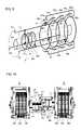
- FIG. 7is an exploded perspective view of a coaxial revolver of the transfer engine.
- FIGS. 8A , 8 B and 8 Care axial sections of the three coaxial revolvers of the transfer engine.
- FIG. 9is a skeleton diagram equivalent to FIG. 6B .
- FIG. 10is a side view of the two transfer engines of the transfer apparatus.
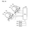
- FIG. 11is a block diagram of the servo drive system of the transfer apparatus.
- FIG. 1shows a chip transfer apparatus 1 embodying the present invention.
- the transfer apparatus 1includes a first carrier 3 , a second carrier 5 and two transfer engines 6 .
- the first carrier 3carries chips 2 on it and feeds the carried chips.
- the second carrier 5carries works 4 , onto which chips 2 can be transferred.
- Each transfer engine 6includes three coaxial revolvers 10 .
- the coaxial revolvers 10 of the two transfer engines 6revolve coaxially with each other around a horizontal axis CL ( FIG. 6B ).
- Each coaxial revolver 10 of one of the engines 6is fitted with an end-effector 71 , 73 or 75 .
- Each coaxial revolver 10 of the other engine 6is fitted with an end-effector 72 , 74 or 76 .
- Each of the end-effectors 71 - 76receives a chip 2 from the first carrier 3 and transfers the received chip onto a work 4 on the second carrier 5 .
- the end-effectors 71 - 76are arranged at intervals in a circle coaxial with the horizontal axis CL ( FIG. 6B ). While the end-effectors 71 - 76 are revolving around the horizontal axis CL, they receive chips 2 in order from the first carrier 3 at a nearly zero speed relative to this carrier synchronously with the rotation of this carrier. While the end-effectors 71 - 76 are revolving around the horizontal axis CL, they transfer in order the received chips 2 to predetermined positions on works 4 on the second carrier 5 at a nearly zero speed relative to this carrier synchronously with the movement of this carrier. During the revolution of each of the end-effectors 71 - 76 , timing adjustment is independently carried out for the reception and transfer on the revolving orbit, and period change control is independently carried out for the speed adjustment at that time.
- FIG. 6BSix angular positions Q 1 -Q 6 are predetermined around the horizontal axis CL ( FIG. 6B ).
- the end-effector 71is in the angular position Q 1 , where it receives a chip 2 from the first carrier 3 .
- the end-effector 72is in the angular position Q 2 , where it is moving toward the second carrier 5 .
- the end-effector 73is in the angular position Q 3 , where it transfers a chip 2 onto a work 4 .
- the other end-effectors 74 , 75 and 76are in the angular positions Q 4 , Q 5 and Q 6 respectively, where they are moving toward the first carrier 3 .
- the first carrier 3is a cylindrical or columnar rotor and adjoins a chip feeder 30 .
- the first carrier 3receives a chip 2 at a point P 0 from the chip feeder 30 and transfers the received chip 2 at a point P 1 to one of the coaxial revolvers 10 .
- the first carrier 3rotates at a constant speed and carries chips 2 at regular intervals on its cylindrical wall.
- the cylindrical wallmay be formed with holes, through which air can be sucked to hold chips 2 on the wall. It is possible to release the held chips 2 by stopping the suction or applying positive pressure at a predetermined rotary position.
- the chip feeder 30takes the form of a roller, around which a tape may temporarily retain chips 2 on it until they are fed. Alternatively, a continuous material might be fed and cut into chips, which might then be fed to the chip feeder 30 .
- the second carrier 5may include a belt, which can be moved by four rollers 51 - 54 .
- the start end of the beltis fed from a roll (not shown), and the other end is taken up by another roll (not shown).
- Each of the two carriers 3 and 5is so adjusted by a drive (not shown) and a drive control system (not shown) as to operate at a constant speed.
- a drivenot shown
- a drive control systemnot shown
- the conditions of the chips 2 and works 4are photographed by three measuring units 103 , 106 and 105 , which may be cameras.
- the image processing of the photographsmakes it possible to detect irregular pitches, abnormal positions, foreign substances and other abnormalities.
- the moving speeds of the chips 2 and works 4are measured by the measuring units 103 , 106 and 105 so that the revolution of the coaxial revolvers 10 can be controlled.
- the transfer apparatus 1transfer chips 2 that are electronic parts for RF reception and transmission onto works 4 each having an antenna 41 .
- the works 4may be carried on the second carrier 5 in the form of a belt.
- the works 4may be printed, photographically formed or otherwise integrally formed on a flexible substrate in the form of a tape as the second carrier 5 .
- Both terminals 42 of the antenna 41 on each work 4may be coated in advance with conductive resin for electric connection.
- Each chip 2is mounted between the antenna terminals 42 on one of the works 4 .
- the RF tagsare so small as to be called sesame chips.
- the RF tagsneed to be tens of microns or some microns in accuracy for the positioning accuracy of the chips 2 . This can be realized by the transfer apparatus 1 .
- the chips 2can be mounted as stated above while the works 4 are conveyed in series without halting.
- the transfer apparatus 1can be used not only to produce RF tags, but also to transfer and mount electronic parts onto IC card parts etc.
- the foregoing high-speed and accurate transfercan be realized by the revolution of the end-effectors.
- the end-effector revolutionwill be described below with reference to FIG. 3 , which shows changes with time in the revolving angles of the end-effectors.
- the curves C 1 -C 6 in FIG. 3represent the movement of the end-effectors 71 - 76 respectively.
- the revolving angles q 1 -q 6 of the end-effectors 71 - 76 at a time t 1correspond to the angular positions Q 1 -Q 6 ( FIG. 1 ) respectively.
- the angular position Q 1is on the plane where the axes of the first carrier 3 and coaxial revolvers 10 extend.
- the angular position Q 1is the starting point of the revolving angles ⁇ .
- the end-effectors 71 - 76revolve counterclockwise in FIG. 1 .
- the end-effectors 71 - 76receive chips 2 from the first carrier 3 cyclically at a period (pitch) T 1 .
- the period T 1is determined by the rotational speed of the first carrier 3 and the intervals at which chips 2 are carried on this carrier.
- the end-effectors 71 - 76receive chips 2 , transfer the received chips and revolve cyclically at a period T 2 .
- the period T 2 for a small number of cyclesis about six times T 1 (T 2 nearly equal 6 ⁇ T 1 ).
- the revolution of each of the six end-effectorsis independently controlled so that chips can be fed and transferred at a speed that is about six times the revolving speed of the end-effectors.
- each end-effectorreceives a chip 2 at the angular position Q 1 , where its revolving angle is zero, at the time t 1 while it is revolving at a speed V 1 .
- the end-effector 71transfers the received chip 2 onto a work at the angular position Q 3 , where its revolving angle is ⁇ 1 , at a time t 2 while it is revolving at a speed V 2 .
- the end-effector 71revolves at a constant speed during a time period a 1 or a 5 so as to move at nearly zero speed relative to the chip synchronously with the moving speed of the chip.
- the end-effector 71revolves at a constant speed during a time period a 3 at nearly zero speed relative to the work synchronously with the moving speed of the work.
- the end-effector 71accelerates and decelerates during time periods a 2 and a 4 respectively while it is revolving in the orbit.
- the camera 105may measure a pitch variation of works 4 on the second carrier 5 , and the end-effector 71 may have to transfer the chip 2 on it onto one of the works a time *t earlier.
- the end-effector 71can be so accelerated as to make the curve of FIG. 4B to pass through a point f 1 in place of a point f. This makes it possible to transfer the chip 2 accurately to the predetermined position on the work 4 .
- by independently controlling the revolution of each of the end-effectors 71 - 76it is possible to transfer chips 2 onto works 4 accurately at high speed.
- Each of the end-effectors 71 - 76is fitted with a suction pad 70 near its one end.
- the suction pad 70has a hole formed through it for pneumatic control.
- the end-effectorreceives a chip by means of suction through the pad hole and transfers the received chip by making the pressure normal or positive.
- the suction pad 70revolves together with the end-effector.
- the transfer engines 6are positioned coaxially with and opposite each other.
- the three end-effectors of one of the setsare positioned alternately with those of the other set in the same circle around the horizontal axis CL.
- FIG. 6Ashows the three end-effectors 71 , 73 and 75 of one of the two transfer engines 6 .
- the transfer engine 6includes three fixed frames 60 a , 60 b and 60 c , four large-diameter coaxial bearings, a hollow shaft 60 and three small-diameter coaxial bearings 61 , 63 and 65 .
- the large-diameter bearingsare positioned between the fixed frames 60 a and 60 c .
- the inner races of the small-diameter bearings 61 , 63 and 65are fixed to the hollow shaft 60 , which is fixed to the fixed frame 60 a .
- the end-effectors 71 , 73 and 75take the form of bars extending eccentrically from and in parallel with the horizontal axis CL.
- the large-diameter and small-diameter bearingssupport the end-effectors 71 , 73 and 75 in such a manner that the end-effectors can revolve on the horizontal axis CL.
- These partsform the associated coaxial revolvers 10 (FIGS. 7 and 8 A- 8 C).
- the end-effector 71is supported at its end portion adjacent to its suction pad 70 by the small-diameter bearing 61 on the hollow shaft 60 .
- the other end portion of the end-effector 71is fixed to the inner race 81 of the large-diameter bearings by a connector ring 90 .
- the inner race 81is supported by an outer race 80 of the large-diameter bearing.
- the outer race 80is fixed to the fixed frame 60 c .
- the inner race 81is fixed to the outer race 82 of the axially adjacent large-diameter bearing by an annular connector 91 .
- the outer periphery of the annular connector 91is surrounded by and fixed to a drive wheel 92 , which is also fixed to the outer race 82 .
- the drive wheel 92has teeth (a precision gear or the like) formed on its outer periphery, which may be driven by a timing belt.
- the outer race 82is supported by an inner race 83 of the large diameter bearing ( FIGS. 6B and 8B ).
- a circumferentially adjacent another end-effector 73is fixed to the inner race 83 by a connector ring 90 ( FIG. 8B ).
- the coaxial revolvers 10 including the end-effectors 73 and 75are constructed similarly to the above-mentioned coaxial revolver 10 including the end-effector 71 ( FIGS. 6B , 7 and 8 A- 8 C). Specifically, end-effectors 73 and 75 are fixed to inner races 83 and 85 of the large-diameter bearings by connector rings 90 . The inner races 83 and 85 are fixed to outer races 84 and 86 of the axially adjacent large-diameter bearings by the annular connectors 93 and 95 respectively. The outer races 84 and 86 of large-diameter bearings can be rotated by drive wheels 94 and 96 . The outer race 86 is supported by an inner race 88 . Those races 86 , 88 are of the “additional” large-diameter bearing. The inner race 88 is fixed to the fixed frame 60 a.
- Each of three coaxial revolvers 10includes one end-effector, one large-diameter bearing, one annular connector, one drive wheel.
- the annular connectorfixes the inner race and the outer race of the axially adjacent two large-diameter bearings each of which is of one of the circumferentially adjacent two end-effectors.
- the outer race and inner race at both ends of the connected four bearingsare fixed to fixed frames.
- the transfer engine 6is structured so that three coaxial revolvers 10 support each other.
- FIG. 11shows the servo drive system of the transfer apparatus.
- This drive systemincludes a CPU 100 for the servo control of the drive of the coaxial revolvers 10 .
- the CPU 100makes independent servo control of six motors M, each of which drives one of the coaxial revolvers 10 .
- each drive wheel 92 , 94 or 96is connected to a general-purpose servo control system motor so that revolving speed/phase change control and position correction control can be made. It is possible to disperse or cancel the external pressure exerted on the revolving axis through the drive wheels 92 , 94 and 96 , by positioning the three motors M for each drive wheel at different angles around this axis.
- the outer peripheries of the drive wheels 92 , 94 and 96are surrounded by an open space, where various mechanisms can be fitted. This makes it possible to replace the general-purpose servo control system motors with direct drive mechanisms for more accurate control.
- the hollow shaft 60 of each transfer engine 6has three holes 70 a formed through its cylindrical wall and a center hole 70 b formed through its end wall adjacent to the frame 60 a .
- Negative pressure for the chip suctionis applied through the communicating path made of the holes of the suction pads 70 ; the spaces in the end-effectors; holes and slits of the small-diameter bearings 61 , 63 and 65 ; and the shaft holes 70 a and 70 b ; by a pneumatic controller (not shown), which is fitted to the transfer apparatus.
- the small-diameter bearings 61 , 83 and 65are formed with pressure control holes (not shown). While the small-diameter bearings 61 , 83 and 65 are rotating with the end-effectors 71 - 76 , the pressure control holes can be connected to a pipe line (not shown) for release so that chips can be released from the suction pads 70 .
- the present inventionis not limited to the preferred embodiment, which may be modified into various forms.
- a continuous materialmight be cut into chips, which might then be fed at a constant pitch onto the first carrier 3 .
- the transfer apparatusmight be fitted with means of alignment for pitch-stabilizing correction and position correction.
- the transfer apparatusmight also be fitted with a non-halt phase synchronizer for making the work intervals on the second carrier 5 constant without halting the works being fed. This could make the transfer apparatus more efficient.
- the transfer apparatuscan also be used as a converting machine, a printer, a labeler, a semiconductor producing apparatus or the like for transfer-printing of coating liquid on continuous or separated sheets, and an apparatus for transfer, relocation, lamination or arrangement of small chips or labels.
Landscapes
- Engineering & Computer Science (AREA)
- Microelectronics & Electronic Packaging (AREA)
- Computer Hardware Design (AREA)
- Physics & Mathematics (AREA)
- General Physics & Mathematics (AREA)
- Manufacturing & Machinery (AREA)
- Theoretical Computer Science (AREA)
- Condensed Matter Physics & Semiconductors (AREA)
- Power Engineering (AREA)
- Mechanical Engineering (AREA)
- Specific Conveyance Elements (AREA)
- Container, Conveyance, Adherence, Positioning, Of Wafer (AREA)
- Supply And Installment Of Electrical Components (AREA)
- Arrangements For Transmission Of Measured Signals (AREA)
Abstract
Description
1. Field of the Invention
The present invention relates to a transfer apparatus for transferring parts onto works with revolving end-effectors.
2. Description of the Related Art
Conventionally, there has been such an electronic parts mounting apparatus available in the field of semiconductor production for receiving chips, transferring the received chips onto works and arranging, sticking or electrically connecting the transferred chips on the works (e.g., Japanese Laid-Open Patent Publication No. H10-145091). This apparatus is a rotary type mounting apparatus having multiple transfer heads, which revolve to mount chips on works in sequence. The transfer heads are arranged coaxially around a main shaft and revolve in a circular orbit around the shaft. Operation stages are set at fixed positions on the orbit such as a suction stage where the transfer head sucks a chip from a chip feeder, and a mounting stage where the transfer head mounts the sucked chip on the work. The transfer heads stop at each of the operation stages to transfer chips. In order to keep the main shaft rotating while the transfer heads are stopping, the mounting apparatus is equipped with a fixed cam having a curve to substantially stop the transfer heads by canceling the rotational speed transmitted from the main shaft to the heads. Thus an apparatus is realized which can mount chips while its main shaft is continuously rotating.
However such apparatus for mounting electronic parts mentioned above transfers chips by means of transfer heads, the periodic motion is rigid because the motion is generated by mechanical cams. Accordingly, the transfer heads are constrained to move in conjunction with the rotation of the main shaft.
Recently, commodity control by means of disposable type RFID (radio frequency identification) tags is made in several field as a result of advancement of information technology and requirement of the laborsaving for information management. This requires mass production of cheap RFID tags (RF tags or radio tags). The mass production of RF tags may also require following processes or process technologies; feeding electronic parts for RF transmission/reception continuously at a constant pitch without halting them; receiving the fed parts without halting them; transferring the received parts without halting them onto sheet-type works having an antenna element formed on it while the works are moving continuously and are fed side by side in a constant pitch; arranging, sticking, or electrically connecting the parts onto the work. If the periodic motion of the transfer heads is rigidly fixed, following problems may occur for the mass production mentioned above. That is, it is necessary to replace the cam troublesomely for every products of a different size or pitch. Besides, because the motion of the transfer heads is limited, the heads cannot follow an irregular change of the pitch of fed parts or an irregular change of the pitch of moving works. Those transfer heads cannot respond to random pitch changes or real-time fine adjustment, and consequently, accurate parts positioning is impossible.
Another conventional transfer mechanism is known, which includes a single transfer head and has an electronic cam driven by a single motor with which period can be changed. However, the single transfer head is not adaptable for high-speed mass production even though it may ensure positioning accuracy.
Accordingly, the object of the present invention is to provide a random-period chip transfer apparatus that can realize accurate positioning and high-speed transfer, and that can also respond to changes of the speeds and pitches at which chips and works are fed.
In order to attain the above object, according to the present invention, a chip transfer apparatus for transferring chips onto works, comprises a first carrier for carrying chips thereon; a second carrier for carrying works thereon; a plurality of end-effectors receiving chips from the first carrier and transferring the chips onto the works carried by the second carrier; a plurality of coaxial revolvers, each of which has one end-effector, and can revolve around one common axis independently; and servo drives, each of which drives each of coaxial revolvers to independently and randomly change periodic revolving speed of each coaxial revolver; wherein each of the end-effectors is inseparably mounted on each of the coaxial revolvers and distributed in one common circle around the axis, wherein each of the end-effectors moves sequentially keeping their order by the action of said servo drives, and is synchronized with the first carrier movement to receive a chip from the first carrier at substantially zero speed relative to said first carrier, and is synchronized with the second carrier movement to transfer the received chip onto the work on the second carrier at substantially zero speed relative to the second carrier, and is independently changed its revolving speed during the periodic motion including said receiving and transferring motion.
The end-effectors of the coaxial revolvers are arranged in a circle coaxial with the revolvers axis, and are revolved independently in sequence, and sequentially receive chips from the first carrier at substantially zero speed relative to the carrier by synchronizing the end-effector with the carrier, and transfer the received chips onto the works on the second carrier at substantially zero speed relative to the carrier by synchronizing the end-effector with the carrier while they are revolving with each own periodic speed changed and controlled independently. This can realize high positioning accuracy and high-speed transfer in response to changes of the speeds and pitches at which chips and works are fed. For example, if the end-effectors are six in number, they can receive chips fed at a speed that is nearly six times the revolving speed. Chips can be fed at a constant pitch sequentially without halting. The end-effectors can receive the fed chips without halting them and transfer the received chips onto works moving at a constant pitch sequentially without halting.
It is possible to transfer chips accurately to predetermined positions on works by accelerating or decelerating the end-effectors in response to pitch variations of works on the second carrier. Thus, the independent control of the revolution of each end-effector enables free pitch changes and real-time fine adjustments of chips and works, which enable high-speed and accurate transfer. By independently correcting the position of each end-effector, it is possible to achieve tens of microns and some microns in accuracy, thereby improving the productivity and the mounting quality.
Preferably, in the transfer apparatus, each of the coaxial revolvers includes a coaxial bearing arranged in order on the axial direction having an inner race fixed to an outer race of the coaxially adjacent bearing, and having an outer race fixed to an inner race of the coaxially adjacent another bearing; the inner race of the bearing on one end side being fixed to an outer race of an additional bearing which inner race is fixed to one fixed side and the outer race of the bearing on the other end side being fixed to the other fixed side; each of the end-effectors being inseparably fixed to the inner race of the associated bearing, and the outer race of the associated bearing being activated by a rotational driving force of each of the servo drives. In this case, the coaxial revolvers support each other. If the coaxial revolvers are three in number, they can be driven by three general-purpose servo control system motors positioned at different angles around the axis. This makes it possible to average and distribute the external forces exerted on the bearing axis. Because the coaxial revolvers can revolve independently of each other, the drive wheels made up on each outer race of the associated bearing can be connected to general-purpose servo control system motors so that their revolving speed/phase change control and position correction control can be done. Since a space surrounding each of the outer races of the bearings is wide enough, it is possible to house more accurate direct drive/control in place of the general-purpose servo control system.
Preferably, in the transfer apparatus, each of the coaxial revolvers is individually and independently made its periodic speed change and phase control by the operation of the associated servo drive. In this case, independent control of the revolution of each end-effector enables free pitch changes and real-time fine position adjustment of chips and works. This enables high-speed and accurate transfer.
Preferably, the transfer apparatus further comprising a measuring unit for measuring the speed of the chips carried on the first carrier and/or the speed of the works carried on the second carrier; the servo drives being operated on the basis of the measurement result of the measuring unit. In this case, without using indirect information based on the first carrier and/or the second carrier motion control information, it is possible to use directly obtained speed and/or position data of chips and/or works. Therefore accurate and real-time control of the coaxial revolvers revolution is possible. This enables high-speed and accurate transfer.
Preferably, in the transfer apparatus, even if the first and second carriers move at different speeds, each of the end-effectors receives a chip from the first carrier at substantially zero speed relative to the first carrier synchronized with the first carrier movement, and transfers the received chip onto a predetermined position of the work on the second carrier at substantially zero speed relative to the second carrier synchronized with the second carrier movement. This enables high-speed and accurate transfer even in a case where the feeding speed of chips, which depends on the moving speed of the first carrier, is lower than the moving speed of works, which depends on the moving speed of the second carrier. This case may be a case where the end-effectors transfer chips onto works that are larger in size than the chips.
Preferably, in the transfer apparatus, each of the first and second carriers is a rotating cylinder or a conveyor belt. In this case, the end-effectors can receive chips by approaching the chips carried on a rotating cylinder or a running conveyor belt and transfer the received chips onto works by approaching the works carried on a rotating cylinder or a running conveyor belt.
Preferably, in the transfer apparatus, the chips are electronic parts, and the works are IC card parts or RF tag parts in the form of sheets. In this case, it is possible to improve the productivity and quality of IC cards or RF tags by means of the foregoing operation and effect/s of the transfer apparatus.
The end-effectors71-76 are arranged at intervals in a circle coaxial with the horizontal axis CL (FIG. 6B ). While the end-effectors71-76 are revolving around the horizontal axis CL, they receivechips 2 in order from thefirst carrier 3 at a nearly zero speed relative to this carrier synchronously with the rotation of this carrier. While the end-effectors71-76 are revolving around the horizontal axis CL, they transfer in order the receivedchips 2 to predetermined positions onworks 4 on thesecond carrier 5 at a nearly zero speed relative to this carrier synchronously with the movement of this carrier. During the revolution of each of the end-effectors71-76, timing adjustment is independently carried out for the reception and transfer on the revolving orbit, and period change control is independently carried out for the speed adjustment at that time.
Six angular positions Q1-Q6 are predetermined around the horizontal axis CL (FIG. 6B ). InFIG. 1 , the end-effector 71 is in the angular position Q1, where it receives achip 2 from thefirst carrier 3. InFIG. 1 , the end-effector 72 is in the angular position Q2, where it is moving toward thesecond carrier 5. InFIG. 1 , the end-effector 73 is in the angular position Q3, where it transfers achip 2 onto awork 4. InFIG. 1 , the other end-effectors first carrier 3.
Thefirst carrier 3 is a cylindrical or columnar rotor and adjoins achip feeder 30. Thefirst carrier 3 receives achip 2 at a point P0 from thechip feeder 30 and transfers the receivedchip 2 at a point P1 to one of thecoaxial revolvers 10. Normally, thefirst carrier 3 rotates at a constant speed and carrieschips 2 at regular intervals on its cylindrical wall. The cylindrical wall may be formed with holes, through which air can be sucked to holdchips 2 on the wall. It is possible to release the heldchips 2 by stopping the suction or applying positive pressure at a predetermined rotary position. As shown inFIG. 1 , thechip feeder 30 takes the form of a roller, around which a tape may temporarily retainchips 2 on it until they are fed. Alternatively, a continuous material might be fed and cut into chips, which might then be fed to thechip feeder 30.
Thesecond carrier 5 may include a belt, which can be moved by four rollers51-54. The start end of the belt is fed from a roll (not shown), and the other end is taken up by another roll (not shown).
Each of the twocarriers chips 2 are transferred ontoworks 4, the conditions of thechips 2 and works4 are photographed by three measuringunits chips 2 are transferred ontoworks 4, the moving speeds of thechips 2 and works4 are measured by the measuringunits coaxial revolvers 10 can be controlled.
For the production of RF tags, as shown inFIGS. 2A and 2B , thetransfer apparatus 1transfer chips 2 that are electronic parts for RF reception and transmission ontoworks 4 each having anantenna 41. Theworks 4 may be carried on thesecond carrier 5 in the form of a belt. Alternatively, theworks 4 may be printed, photographically formed or otherwise integrally formed on a flexible substrate in the form of a tape as thesecond carrier 5. Bothterminals 42 of theantenna 41 on eachwork 4 may be coated in advance with conductive resin for electric connection. Eachchip 2 is mounted between theantenna terminals 42 on one of theworks 4. The RF tags are so small as to be called sesame chips. The RF tags need to be tens of microns or some microns in accuracy for the positioning accuracy of thechips 2. This can be realized by thetransfer apparatus 1. For mass production of cheap RF tags, thechips 2 can be mounted as stated above while theworks 4 are conveyed in series without halting. Thetransfer apparatus 1 can be used not only to produce RF tags, but also to transfer and mount electronic parts onto IC card parts etc.
The foregoing high-speed and accurate transfer can be realized by the revolution of the end-effectors. The end-effector revolution will be described below with reference toFIG. 3 , which shows changes with time in the revolving angles of the end-effectors. The curves C1-C6 inFIG. 3 represent the movement of the end-effectors71-76 respectively. The revolving angles q1-q6 of the end-effectors71-76 at a time t1 correspond to the angular positions Q1-Q6 (FIG. 1 ) respectively. The angular position Q1 is on the plane where the axes of thefirst carrier 3 andcoaxial revolvers 10 extend. The angular position Q1 is the starting point of the revolving angles θ. The end-effectors71-76 revolve counterclockwise inFIG. 1 . With reference toFIG. 3 , the end-effectors71-76 receivechips 2 from thefirst carrier 3 cyclically at a period (pitch) T1. The period T1 is determined by the rotational speed of thefirst carrier 3 and the intervals at which chips2 are carried on this carrier. The end-effectors71-76 receivechips 2, transfer the received chips and revolve cyclically at a period T2. The period T2 for a small number of cycles is about six times T1 (T2 nearly equal 6×T1). The average period T2 for a large number of cycles is six times T1 (T2=6×T1). The revolution of each of the six end-effectors is independently controlled so that chips can be fed and transferred at a speed that is about six times the revolving speed of the end-effectors.
The revolution of each end-effector will be described with reference toFIGS. 4A and 4B , which show the change with time in the revolving angle of the end-effector 71. The end-effector 71 receives achip 2 at the angular position Q1, where its revolving angle is zero, at the time t1 while it is revolving at a speed V1. The end-effector 71 transfers the receivedchip 2 onto a work at the angular position Q3, where its revolving angle is θ1, at a time t2 while it is revolving at a speed V2. The end-effector 71 returns to the angular position Q1, where its revolving angle is 2π, at a time t3 (=t1+T2). In order to receive achip 2 moving on the first carrier, the end-effector 71 revolves at a constant speed during a time period a1 or a5 so as to move at nearly zero speed relative to the chip synchronously with the moving speed of the chip. Likewise, in order to transfer achip 2 onto a work moving on the second carrier, the end-effector 71 revolves at a constant speed during a time period a3 at nearly zero speed relative to the work synchronously with the moving speed of the work. The end-effector 71 accelerates and decelerates during time periods a2 and a4 respectively while it is revolving in the orbit.
Not only speed adjustment but also time adjustment are made during the time periods a2 and a4. For example, with reference toFIGS. 1 and 4B , thecamera 105 may measure a pitch variation ofworks 4 on thesecond carrier 5, and the end-effector 71 may have to transfer thechip 2 on it onto one of the works a time *t earlier. In this case, the end-effector 71 can be so accelerated as to make the curve ofFIG. 4B to pass through a point f1 in place of a point f. This makes it possible to transfer thechip 2 accurately to the predetermined position on thework 4. Thus, by independently controlling the revolution of each of the end-effectors71-76, it is possible to transferchips 2 ontoworks 4 accurately at high speed.
The structure of thecoaxial revolvers 10 andtransfer engines 6 will be described below with reference toFIGS. 5-10 . Each of the end-effectors71-76 is fitted with asuction pad 70 near its one end. Thesuction pad 70 has a hole formed through it for pneumatic control. The end-effector receives a chip by means of suction through the pad hole and transfers the received chip by making the pressure normal or positive. Thesuction pad 70 revolves together with the end-effector. As shown inFIG. 5 , the three end-effectors effectors FIG. 10 , thetransfer engines 6 are positioned coaxially with and opposite each other. The three end-effectors of one of the sets are positioned alternately with those of the other set in the same circle around the horizontal axis CL.
The revolving mechanisms of thecoaxial revolvers 10 will be described below. The end-effector 71 is supported at its end portion adjacent to itssuction pad 70 by the small-diameter bearing 61 on thehollow shaft 60. The other end portion of the end-effector 71 is fixed to theinner race 81 of the large-diameter bearings by aconnector ring 90. Theinner race 81 is supported by anouter race 80 of the large-diameter bearing. Theouter race 80 is fixed to the fixedframe 60c. Theinner race 81 is fixed to theouter race 82 of the axially adjacent large-diameter bearing by anannular connector 91. The outer periphery of theannular connector 91 is surrounded by and fixed to adrive wheel 92, which is also fixed to theouter race 82. Thedrive wheel 92 has teeth (a precision gear or the like) formed on its outer periphery, which may be driven by a timing belt. Theouter race 82 is supported by aninner race 83 of the large diameter bearing (FIGS. 6B and 8B ). A circumferentially adjacent another end-effector 73 is fixed to theinner race 83 by a connector ring90 (FIG. 8B ).
Thecoaxial revolvers 10 including the end-effectors coaxial revolver 10 including the end-effector71 (FIGS. 6B ,7 and8A-8C). Specifically, end-effectors inner races inner races outer races annular connectors outer races drive wheels outer race 86 is supported by aninner race 88. Thoseraces inner race 88 is fixed to the fixedframe 60a.
Each of threecoaxial revolvers 10 includes one end-effector, one large-diameter bearing, one annular connector, one drive wheel. The annular connector fixes the inner race and the outer race of the axially adjacent two large-diameter bearings each of which is of one of the circumferentially adjacent two end-effectors. The outer race and inner race at both ends of the connected four bearings are fixed to fixed frames. Thus the large-diameter (three plus one additional) four bearings are connected by so-called cascade connection. Thetransfer engine 6 is structured so that threecoaxial revolvers 10 support each other.
The suction and release of chips by the end-effectors71-76 will be described below with reference toFIG. 6B . Thehollow shaft 60 of eachtransfer engine 6 has threeholes 70aformed through its cylindrical wall and acenter hole 70bformed through its end wall adjacent to theframe 60a. Negative pressure for the chip suction is applied through the communicating path made of the holes of thesuction pads 70; the spaces in the end-effectors; holes and slits of the small-diameter bearings diameter bearings diameter bearings suction pads 70.
The present invention is not limited to the preferred embodiment, which may be modified into various forms. For example, a continuous material might be cut into chips, which might then be fed at a constant pitch onto thefirst carrier 3. In this case, the transfer apparatus might be fitted with means of alignment for pitch-stabilizing correction and position correction. The transfer apparatus might also be fitted with a non-halt phase synchronizer for making the work intervals on thesecond carrier 5 constant without halting the works being fed. This could make the transfer apparatus more efficient. The transfer apparatus can also be used as a converting machine, a printer, a labeler, a semiconductor producing apparatus or the like for transfer-printing of coating liquid on continuous or separated sheets, and an apparatus for transfer, relocation, lamination or arrangement of small chips or labels.
Claims (14)
1. A chip transfer apparatus for transferring chips onto works, the apparatus comprising:
a first carrier for carrying chips thereon;
a second carrier for carrying works thereon;
a plurality of end-effectors configured to receive chips from said first carrier and to transfer the chips onto the works carried by the second carrier;
a first plurality of coaxial revolvers, each of which has one of said end-effectors, each of the coaxial revolvers configured to revolve around one stationary common axis independently; and
a plurality of servo drives, each configured to drive a respective one of said coaxial revolvers independently and to change a periodic revolving speed of the respective coaxial revolver,
wherein each of said end-effectors is affixed to a respective one of said coaxial revolvers and all of the end-effectors are distributed in one stationary common circle around said one stationary common axis,
wherein each of said end-effectors revolves independently along the one stationary common circle in sequential order in a periodic motion by the action of said servo drives, and
wherein the servo drives are configured to change a respective revolving speed of each of the end-effectors independently during the periodic motion.
2. The transfer apparatus according toclaim 1 , further comprising:
a rigid frame including a first end and a second end, the first and second ends disposed oppositely along the axial direction;
a first plurality of coaxial bearings including a first coaxial bearing through a last coaxial bearing, each of the coaxial bearings respectively including an inner race and an outer race, the outer race of the first coaxial bearing being affixed to the first end of the rigid frame and the inner race of the last coaxial bearing being affixed to the second end of the rigid frame,
wherein each of said coaxial revolvers includes a respective one of the first through a next-to-last one of the coaxial bearings arranged in sequential order in the axial direction,
wherein the inner race of each of the first through the next-to-last one of the coaxial bearings is fixed to an outer race of an adjacent coaxial bearing, and
each of said end-effectors being connected to a corresponding coaxial revolver proximal to the inner race of the associated bearing, and the outer race of the associated bearing being activated by a rotational driving force of a corresponding one of said servo drives.
3. The transfer apparatus according toclaim 2 , further comprising a second plurality of coaxial bearings, the second plurality of coaxial bearings having a diameter smaller than the first plurality of coaxial bearings.
4. The transfer apparatus according toclaim 1 , wherein each of the servo drives is configured to individually and independently change the periodic revolving speed and phase control of a respective one of the coaxial revolvers.
5. The transfer apparatus according toclaim 4 , further comprising:
a measuring unit configured to measure a speed of the chip carried on the first carrier and/or a speed of the work carried on the second carrier,
wherein the servo drives operates based on a measurement from the measuring unit.
6. The transfer apparatus according toclaim 5 , wherein the measuring unit includes a camera.
7. The transfer apparatus according toclaim 5 , further comprising:
a control unit configured to receive input from the measuring unit and to control the plurality of servo drives.
8. The transfer apparatus according toclaim 4 , wherein, even when the first and second carriers move in a forward direction at different speeds, each of the end-effectors receives a chip from the first carrier at substantially zero speed in the forward direction relative to the first carrier synchronized with the first carrier movement, and transfers the received chip onto a predetermined position of the work on the second carrier at substantially zero speed in the forward direction relative to the second carrier synchronized with the second carrier movement.
9. The transfer apparatus according toclaim 8 , wherein each of the first and second carriers is a rotating cylinder or a conveyor belt.
10. The transfer apparatus according toclaim 1 , wherein the chips are electronic parts, and
wherein the works are IC card parts or RF tag parts in a form of sheets.
11. The transfer apparatus according toclaim 1 , wherein each end-effector is further configured to receive the chip from the first carrier in synchronization with the first carrier such that the end-effector has substantially zero speed with respect to the chip in a forward direction in which the first carrier conveys the chip when the end-effector receives the chip, and
wherein each end-effector is further configured to transfer the chip onto a work conveyed by the second carrier in synchronization with the second carrier such that the end-effector has substantially zero speed with respect to the work in a second direction in which the second carrier conveys the work when the end-effector transfers the chip onto the work.
12. The transfer apparatus according toclaim 1 , wherein the end-effectors include a pneumatic mechanism.
13. The transfer apparatus according toclaim 1 , further comprising:
a second plurality of coaxial revolvers opposite the first plurality of coaxial revolvers, and
a second plurality of servo drives configured to rotate the second plurality of coaxial revolvers about the one common axis,
wherein each of the second plurality of coaxial revolvers is distributed around the one common circle alternatingly with adjacent ones of the first plurality of coaxial revolvers.
14. The transfer apparatus according toclaim 1 , wherein the servo drives include a motor operatively connected to a drive wheel.
Priority Applications (1)
| Application Number | Priority Date | Filing Date | Title |
|---|---|---|---|
| US11/849,806US7643904B2 (en) | 2003-02-07 | 2007-09-04 | Random-period chip transfer method |
Applications Claiming Priority (2)
| Application Number | Priority Date | Filing Date | Title |
|---|---|---|---|
| JP2003031165AJP3739752B2 (en) | 2003-02-07 | 2003-02-07 | Small-piece transfer device capable of random-cycle shifting |
| JP2003-31165 | 2003-02-07 |
Related Child Applications (1)
| Application Number | Title | Priority Date | Filing Date |
|---|---|---|---|
| US11/849,806DivisionUS7643904B2 (en) | 2003-02-07 | 2007-09-04 | Random-period chip transfer method |
Publications (2)
| Publication Number | Publication Date |
|---|---|
| US20040154161A1 US20040154161A1 (en) | 2004-08-12 |
| US7278203B2true US7278203B2 (en) | 2007-10-09 |
Family
ID=32820878
Family Applications (2)
| Application Number | Title | Priority Date | Filing Date |
|---|---|---|---|
| US10/677,180Expired - LifetimeUS7278203B2 (en) | 2003-02-07 | 2003-10-02 | Random-period chip transfer apparatus |
| US11/849,806Expired - LifetimeUS7643904B2 (en) | 2003-02-07 | 2007-09-04 | Random-period chip transfer method |
Family Applications After (1)
| Application Number | Title | Priority Date | Filing Date |
|---|---|---|---|
| US11/849,806Expired - LifetimeUS7643904B2 (en) | 2003-02-07 | 2007-09-04 | Random-period chip transfer method |
Country Status (8)
| Country | Link |
|---|---|
| US (2) | US7278203B2 (en) |
| EP (1) | EP1595278B1 (en) |
| JP (1) | JP3739752B2 (en) |
| KR (1) | KR100849934B1 (en) |
| CN (1) | CN100349256C (en) |
| DE (1) | DE602004010071T2 (en) |
| TW (1) | TWI322647B (en) |
| WO (1) | WO2004070797A1 (en) |
Cited By (23)
| Publication number | Priority date | Publication date | Assignee | Title |
|---|---|---|---|---|
| US20050284917A1 (en)* | 2004-06-24 | 2005-12-29 | Checkpoint Systems, Inc. | Die attach area cut-on-fly method and apparatus |
| US20070053310A1 (en)* | 2005-09-08 | 2007-03-08 | Haruhiko Ishizawa | Manufacturing method of electronic device |
| US20070085069A1 (en)* | 2003-12-26 | 2007-04-19 | Shinko Electric Co., Ltd. | Method and apparatus for manufacturing ic chip packaged device |
| US20070107205A1 (en)* | 2003-05-08 | 2007-05-17 | Bernhard Mende | Device and method for linking microchip modules with antennas |
| US20070161154A1 (en)* | 2004-01-15 | 2007-07-12 | Hitachi Chemical Co., Ltd. | Manufacturing method for electronic device |
| US20080003092A1 (en)* | 2006-06-30 | 2008-01-03 | Petar Baclija | Rotary union connection |
| US20090061561A1 (en)* | 2005-04-18 | 2009-03-05 | Kousuke Tanaka | Method of producing electronic apparatus |
| US20090206012A1 (en)* | 2006-06-23 | 2009-08-20 | Tim Wirsching | Sorting device and method for sorting rfid tags |
| USD624059S1 (en)* | 2006-11-02 | 2010-09-21 | First Impression Systems, Llc | EAS antenna |
| US20100326796A1 (en)* | 2009-06-30 | 2010-12-30 | Bradley Edward Walsh | Methods and apparatuses for transferring discrete articles between carriers |
| US8020283B2 (en)* | 2004-09-22 | 2011-09-20 | Avery Dennison Corporation | High-speed RFID circuit placement device |
| US20120110840A1 (en)* | 2007-11-01 | 2012-05-10 | Makoto Takayanagi | Chip mounter |
| US20120210554A1 (en)* | 2011-02-23 | 2012-08-23 | Samsung Techwin Co., Ltd. | Apparatus and method for picking up and mounting bare dies |
| US8607959B2 (en) | 2012-04-16 | 2013-12-17 | The Procter & Gamble Company | Rotational assemblies and methods for transferring discrete articles |
| US20140030849A1 (en)* | 2011-11-07 | 2014-01-30 | Taiwan Semiconductor Manufacturing Company, Ltd. | Pick-and-Place Tool for Packaging Process |
| US8720666B2 (en) | 2012-04-16 | 2014-05-13 | The Procter & Gamble Company | Apparatuses for transferring discrete articles |
| US8820513B2 (en) | 2012-04-16 | 2014-09-02 | The Procter & Gamble Company | Methods for transferring discrete articles |
| US8833542B2 (en) | 2012-04-16 | 2014-09-16 | The Procter & Gamble Company | Fluid systems and methods for transferring discrete articles |
| US9266314B2 (en) | 2012-10-23 | 2016-02-23 | The Procter & Gamble Company | Carrier members or transfer surfaces having a resilient member |
| US9463942B2 (en) | 2013-09-24 | 2016-10-11 | The Procter & Gamble Company | Apparatus for positioning an advancing web |
| US9511952B1 (en) | 2015-06-23 | 2016-12-06 | The Procter & Gamble Company | Methods for transferring discrete articles |
| US9511951B1 (en) | 2015-06-23 | 2016-12-06 | The Procter & Gamble Company | Methods for transferring discrete articles |
| US20230139972A1 (en)* | 2020-01-27 | 2023-05-04 | Panasonic Holding Corporation | Laminating device, and manufacturing device for laminated electrode assembly |
Families Citing this family (83)
| Publication number | Priority date | Publication date | Assignee | Title |
|---|---|---|---|---|
| US7384496B2 (en)* | 2004-02-23 | 2008-06-10 | Checkpoint Systems, Inc. | Security tag system for fabricating a tag including an integrated surface processing system |
| JP4734857B2 (en)* | 2004-06-25 | 2011-07-27 | シンフォニアテクノロジー株式会社 | IC chip assembly manufacturing apparatus |
| JP4692718B2 (en)* | 2004-12-07 | 2011-06-01 | シンフォニアテクノロジー株式会社 | IC chip assembly manufacturing apparatus |
| CN101023009A (en)* | 2004-09-22 | 2007-08-22 | 哈里斯股份有限公司 | Conveyance device |
| CN101018722B (en)* | 2004-09-22 | 2011-09-07 | 哈里斯股份有限公司 | Transfer apparatus |
| DE102004056238B3 (en)* | 2004-11-22 | 2006-03-30 | Arccure Technologies Gmbh | Method and arrangement for the production of RFID tags |
| CN101073296B (en)* | 2004-12-03 | 2011-07-06 | 哈里斯股份有限公司 | Interposer Engagement Device |
| EP1833290A4 (en)* | 2004-12-03 | 2009-11-11 | Hallys Corp | Electronic component production method and electronic component production equipment |
| ATE488985T1 (en) | 2004-12-03 | 2010-12-15 | Hallys Corp | INTERMEDIATE BONDING DEVICE |
| WO2006067207A1 (en)* | 2004-12-23 | 2006-06-29 | Crown Packaging Technology, Inc. | Multi-stage process handling equipment |
| EP1694107A1 (en)* | 2005-02-17 | 2006-08-23 | KLARER, Christoph | Device and method for picking and delivering an electronic component |
| DE102005016930A1 (en)* | 2005-03-09 | 2006-09-21 | Mühlbauer Ag | RFID chip and strip substrate contact surfaces electrical and mechanical connection establishing method for transponder, involves hooking chip surfaces having hooks/lugs with substrate surfaces having hooks/lugs with size in nanometer range |
| WO2006109678A1 (en)* | 2005-04-06 | 2006-10-19 | Hallys Corporation | Electronic component manufacturing apparatus |
| US20090166431A1 (en)* | 2005-04-18 | 2009-07-02 | Hallys Corporation | Electronic component and manufacturing method thereof |
| US7623034B2 (en)* | 2005-04-25 | 2009-11-24 | Avery Dennison Corporation | High-speed RFID circuit placement method and device |
| DE102005026127B4 (en)* | 2005-06-07 | 2007-02-08 | Koenig & Bauer Ag | Printing machine and a method for producing a printed product |
| CN101209007A (en)* | 2005-06-27 | 2008-06-25 | 松下电器产业株式会社 | Mounting Condition Determination Method |
| US7569932B2 (en)* | 2005-11-18 | 2009-08-04 | Checkpoint Systems, Inc. | Rotary chip attach |
| US7555826B2 (en) | 2005-12-22 | 2009-07-07 | Avery Dennison Corporation | Method of manufacturing RFID devices |
| DE102006014437B4 (en)* | 2006-03-27 | 2010-03-11 | Mühlbauer Ag | Method and device for the production of RFID smart labels or smart label inlays |
| US7828217B2 (en)* | 2006-03-27 | 2010-11-09 | Muhlbauer Ag | Method and device for producing RFID smart labels or smart label inlays |
| JP4829033B2 (en)* | 2006-08-09 | 2011-11-30 | 株式会社小森コーポレーション | Information recording medium supply device |
| JP5226525B2 (en)* | 2006-10-06 | 2013-07-03 | 株式会社 ハリーズ | Expander unit, and electronic component manufacturing apparatus including the expander unit |
| US7823269B2 (en)* | 2006-10-17 | 2010-11-02 | Tagsys Sas | Method for manufacturing an auxiliary antenna |
| JP5234929B2 (en)* | 2008-06-06 | 2013-07-10 | 株式会社 ハリーズ | Transfer equipment |
| FR2933681B1 (en)* | 2008-07-10 | 2011-04-29 | Thomas Cocirta | DEVICE FOR MOVING AND POSITIONING CONTAINERS BY INDEPENDENT AND RE-CIRCULATING TROLLEYS |
| KR101017673B1 (en)* | 2008-07-18 | 2011-02-25 | 주식회사 에이스테크놀로지 | Built-in antenna for the headset |
| EP2398723A1 (en)* | 2009-02-20 | 2011-12-28 | AMB Apparate + Maschinenbau GmbH | Device for separating disc-shaped elements |
| US20110015754A1 (en)* | 2009-07-16 | 2011-01-20 | Teknimed | Articular implant comprising at least two cavities |
| JP5672067B2 (en)* | 2010-03-09 | 2015-02-18 | 株式会社リコー | Method and apparatus for producing reversible thermosensitive recording medium, and reversible thermosensitive recording medium |
| US8701271B2 (en)* | 2010-04-14 | 2014-04-22 | Avery Dennison Corporation | Method of assembly of articles |
| TWI402931B (en)* | 2010-08-16 | 2013-07-21 | Mpi Corp | Grain conveyor |
| US10574016B2 (en)* | 2011-03-13 | 2020-02-25 | Norman R BYRNE | Process for forming end product with initial and simultaneous formation of subcomponents from separate work pieces |
| US9061832B2 (en)* | 2011-11-21 | 2015-06-23 | R.A. Jones & Co. | Pouch transfer apparatus and methods |
| KR20140099857A (en)* | 2011-12-07 | 2014-08-13 | 이스메카 세미컨덕터 홀딩 에스.아. | A Component Handing Assembly |
| JP2013137285A (en)* | 2011-12-28 | 2013-07-11 | Advantest Corp | Pitch change device, electronic component handling device and electronic component testing device |
| JP2013137284A (en) | 2011-12-28 | 2013-07-11 | Advantest Corp | Electronic component transfer device, electronic component handling device and electronic component testing device |
| EP2610189B1 (en)* | 2011-12-30 | 2015-06-17 | Krones AG | Method and device for transferring container decorations |
| CN103544519B (en)* | 2012-07-13 | 2016-05-11 | 东莞市锐祥智能卡科技有限公司 | The method of double-interface card sheet automatic wire arrangement and groove milling and device thereof |
| WO2014040061A1 (en)* | 2012-09-10 | 2014-03-13 | Ortho Transmission, Llc | Transcutaneous implant for skeletal attachment of external prosthetic devices |
| JP2014075531A (en)* | 2012-10-05 | 2014-04-24 | Samsung Techwin Co Ltd | Component mounting apparatus |
| TWI474432B (en)* | 2012-11-15 | 2015-02-21 | Lextar Electronics Corp | Die grain positioning device, grain positioning system with grain positioning device and grain positioning method of light emitting diode display panel |
| CA2889253C (en) | 2012-11-23 | 2015-11-17 | Transformix Engineering Inc. | Computer numerical control assembly or processing of components |
| CN103182577B (en)* | 2013-01-21 | 2015-06-03 | 广州市明森机电设备有限公司 | Chip welding method of dual-interface card and equipment thereof |
| US9181036B2 (en)* | 2013-02-27 | 2015-11-10 | Graham Packaging Company, L.P. | Automatic rotary transfer apparatus and method |
| US9763370B2 (en)* | 2013-03-15 | 2017-09-12 | National Technology & Engineering Solutions Of Sandia, Llc | Apparatus for assembly of microelectronic devices |
| CN103241403A (en)* | 2013-05-24 | 2013-08-14 | 无锡市崇安区科技创业服务中心 | Automatic LED braiding device |
| JP5844774B2 (en)* | 2013-06-06 | 2016-01-20 | アイダエンジニアリング株式会社 | Servo transfer feeder and control method of servo transfer feeder |
| EP3060513B1 (en) | 2013-10-25 | 2017-07-05 | Transformix Engineering Inc. | Flexible feeding and closing machine for hinged caps |
| DE102014104230A1 (en)* | 2014-03-26 | 2015-10-01 | Osram Opto Semiconductors Gmbh | Radiation-emitting component and method for producing a radiation-emitting component |
| CN104148833B (en)* | 2014-08-01 | 2015-09-30 | 广州市明森机电设备有限公司 | A kind of Double interface intelligent card chip welding method and welding equipment |
| US9633883B2 (en) | 2015-03-20 | 2017-04-25 | Rohinni, LLC | Apparatus for transfer of semiconductor devices |
| GB2549250B (en)* | 2016-02-15 | 2021-06-30 | Pragmatic Printing Ltd | Apparatus and method for manufacturing plurality of electronic circuits |
| JP6312270B2 (en)* | 2016-03-25 | 2018-04-18 | 株式会社写真化学 | Electronic device manufacturing method and device using device chip |
| DE102016115186A1 (en)* | 2016-08-16 | 2018-02-22 | Osram Opto Semiconductors Gmbh | Method for mounting semiconductor chips and device for transferring semiconductor chips |
| CN107887295B (en)* | 2016-09-30 | 2019-07-23 | 上海微电子装备(集团)股份有限公司 | A kind of chip bonding device and bonding method |
| US10141215B2 (en) | 2016-11-03 | 2018-11-27 | Rohinni, LLC | Compliant needle for direct transfer of semiconductor devices |
| US10471545B2 (en) | 2016-11-23 | 2019-11-12 | Rohinni, LLC | Top-side laser for direct transfer of semiconductor devices |
| US10504767B2 (en) | 2016-11-23 | 2019-12-10 | Rohinni, LLC | Direct transfer apparatus for a pattern array of semiconductor device die |
| CN106783717A (en)* | 2016-12-23 | 2017-05-31 | 合肥矽迈微电子科技有限公司 | Flip-chip patch device and method |
| US10062588B2 (en) | 2017-01-18 | 2018-08-28 | Rohinni, LLC | Flexible support substrate for transfer of semiconductor devices |
| GB2563600B (en)* | 2017-06-19 | 2022-05-11 | Pragmatic Printing Ltd | Apparatus and method for manufacturing plurality of electronic circuits |
| DE102017124582A1 (en)* | 2017-10-20 | 2019-04-25 | Asm Assembly Systems Gmbh & Co. Kg | Complementary tool for chip transfer device with removal tool and turning tool |
| CN108323150A (en)* | 2017-12-29 | 2018-07-24 | 重庆市中光电显示技术有限公司 | FPC feeding machines |
| TWI646618B (en)* | 2018-01-09 | 2019-01-01 | 宏碁股份有限公司 | Micro component transfer device and related method |
| CN108454998B (en)* | 2018-03-20 | 2023-06-23 | 湖州市湖芯物联网科技有限公司 | RFID label continuous production system and process |
| US10410905B1 (en) | 2018-05-12 | 2019-09-10 | Rohinni, LLC | Method and apparatus for direct transfer of multiple semiconductor devices |
| US11094571B2 (en) | 2018-09-28 | 2021-08-17 | Rohinni, LLC | Apparatus to increase transferspeed of semiconductor devices with micro-adjustment |
| IT201800009341A1 (en)* | 2018-10-11 | 2020-04-11 | Kern Italia Srl | Machine for applying cards on paper supports and the like. |
| DE102018009475A1 (en)* | 2018-12-03 | 2020-06-04 | Giesecke+Devrient Currency Technology Gmbh | Application and fastening of individual elements on a substrate web |
| TWI686895B (en)* | 2019-04-19 | 2020-03-01 | 台灣愛司帝科技股份有限公司 | Chip transferring machine |
| CN110012657A (en)* | 2019-05-15 | 2019-07-12 | 深圳市兴华炜科技有限公司 | The transfer method and Related product of high-speed paster |
| CN111115244B (en)* | 2020-01-13 | 2021-08-27 | 山东大学 | Device and method for automatically grabbing samples on conveyor belt |
| DE102020001439B3 (en)* | 2020-02-21 | 2021-06-10 | Mühlbauer Gmbh & Co. Kg | Apparatus and method for transferring electronic components from a first to a second carrier |
| CN111313039B (en)* | 2020-03-30 | 2024-06-04 | 江苏氢导智能装备有限公司 | Laminating equipment |
| AR118939A1 (en)* | 2020-05-15 | 2021-11-10 | Marisa Rosana Lattanzi | COMBINED MACHINE TO PRODUCE LAMINAR SEPARATORS FOR PRODUCTS CONTAINED IN BOXES AND DRAWERS |
| US20220059406A1 (en)* | 2020-08-21 | 2022-02-24 | Advanced Semiconductor Engineering, Inc. | Method for manufacturing semiconductor package |
| CN113369874B (en)* | 2021-07-23 | 2023-04-21 | 明基生物技术(上海)有限公司 | Dialyser cap mounting machine |
| CN114194452B (en)* | 2022-02-17 | 2022-04-26 | 四川永星电子有限公司 | Automatic detection mechanism for S parameter of radio frequency chip type load band |
| JP2023149779A (en)* | 2022-03-31 | 2023-10-13 | 本田技研工業株式会社 | Joint device |
| CN116117475B (en)* | 2023-01-31 | 2024-01-23 | 东台市凯润精密机械股份有限公司 | Cloud server rack component is pressed and is riveted mobile conveying device |
| CN116631929B (en)* | 2023-07-24 | 2024-01-05 | 广东工业大学 | A chip transfer method, system, equipment and medium based on a swing arm crystal bonding machine |
| CN119812088B (en)* | 2025-03-13 | 2025-05-16 | 芯蓥智铖(重庆)科技有限公司 | A semiconductor product handling control method, system and storage medium |
Citations (180)
| Publication number | Priority date | Publication date | Assignee | Title |
|---|---|---|---|---|
| US3946961A (en) | 1970-03-25 | 1976-03-30 | Steiner American Corporation | Automatic towel winding machine |
| US4506779A (en)* | 1980-12-12 | 1985-03-26 | G.D. Societa Per Azioni | Device for transferring bar shaped articles |
| JPS60227428A (en) | 1984-04-26 | 1985-11-12 | Shinkawa Ltd | Chip bonding device |
| US4558397A (en) | 1983-12-19 | 1985-12-10 | Amp Incorporated | Interposer connector for surface mounting a ceramic chip carrier to a printed circuit board |
| US4558778A (en)* | 1982-06-23 | 1985-12-17 | Sasib S.P.A. | Transferring device for rod-like articles |
| US4619043A (en) | 1983-05-02 | 1986-10-28 | Tdk Corporation | Apparatus and method for mounting chip type electronic parts |
| US4656478A (en) | 1984-07-30 | 1987-04-07 | Asulab S.A. | Passive transponder for locating avalanche victims |
| US4746618A (en) | 1987-08-31 | 1988-05-24 | Energy Conversion Devices, Inc. | Method of continuously forming an array of photovoltaic cells electrically connected in series |
| US4767487A (en)* | 1985-10-18 | 1988-08-30 | Kimberly-Clark Corporation | Method for repositioning discrete articles |
| JPH01308097A (en) | 1988-06-07 | 1989-12-12 | Hitachi Ltd | Electronic component mounting equipment |
| US4915565A (en) | 1984-03-22 | 1990-04-10 | Sgs-Thomson Microelectronics, Inc. | Manipulation and handling of integrated circuit dice |
| JPH0298902A (en) | 1988-10-05 | 1990-04-11 | Taiyo Yuden Co Ltd | Transfer apparatus of chip-shaped electronic component |
| US4951388A (en)* | 1988-06-21 | 1990-08-28 | Matsushita Electric Industrial Co., Ltd. | Method of mounting electronic components |
| JPH0322023B2 (en) | 1981-08-24 | 1991-03-26 | Canon Kk | |
| US5078375A (en) | 1990-12-06 | 1992-01-07 | Tamarack Products, Inc. | Method of superposing webs |
| US5153983A (en)* | 1990-02-15 | 1992-10-13 | Matsushita Electric Industrial Co., Ltd. | Rotary head type electrical component placing apparatus |
| US5188212A (en) | 1991-05-27 | 1993-02-23 | Winkler & Dunnebier Maschinenfabrik Und Eisengiesserei Kg | Rotating transport apparatus |
| EP0534454A1 (en) | 1991-09-26 | 1993-03-31 | Japan Tobacco Inc. | Work mounting apparatus |
| US5235736A (en) | 1992-06-15 | 1993-08-17 | Motorola, Inc. | Self-fixturing method for assembling an antenna/receiver combination |
| JPH05235592A (en) | 1992-02-26 | 1993-09-10 | Matsushita Electric Ind Co Ltd | Chip type electronic parts aligning and supplying device |
| US5399224A (en) | 1992-09-17 | 1995-03-21 | Thomas J. Lipton Co. | Method and apparatus for producing tagged articles |
| WO1995021423A1 (en) | 1994-02-04 | 1995-08-10 | Giesecke & Devrient Gmbh | Data carrier with an electronic module and process for producing the same |
| US5528222A (en) | 1994-09-09 | 1996-06-18 | International Business Machines Corporation | Radio frequency circuit and memory in thin flexible package |
| US5564888A (en) | 1993-09-27 | 1996-10-15 | Doan; Carl V. | Pick and place machine |
| EP0749270A1 (en) | 1995-06-14 | 1996-12-18 | Matsushita Electric Industrial Co., Ltd. | Automatic electronic part mounting apparatus |
| US5612068A (en)* | 1994-03-14 | 1997-03-18 | Leybold Aktiengesellschaft | Apparatus for the transfer of substrates |
| US5615476A (en) | 1993-10-26 | 1997-04-01 | Giesecke & Devrient Gmbh | Method for producing identity cards having electronic modules |
| JPH09240176A (en) | 1996-03-08 | 1997-09-16 | Olympus Optical Co Ltd | Ic card and its manufacture |
| US5690773A (en) | 1994-02-24 | 1997-11-25 | Gemplus Card International | Method for the manufacture of a contact-free or hybrid card |
| US5700536A (en) | 1996-02-07 | 1997-12-23 | Tamarack Products, Inc. | Integrated label, method and apparatus |
| JPH1050736A (en) | 1996-08-06 | 1998-02-20 | Tosok Corp | Die bonding head of die bonder |
| US5751256A (en) | 1994-03-04 | 1998-05-12 | Flexcon Company Inc. | Resonant tag labels and method of making same |
| JPH10145091A (en) | 1996-11-08 | 1998-05-29 | Matsushita Electric Ind Co Ltd | Electronic component mounting equipment |
| JPH10163252A (en) | 1996-11-28 | 1998-06-19 | Matsushita Electric Ind Co Ltd | Flip chip mounting device |
| US5778525A (en)* | 1995-11-06 | 1998-07-14 | Matsushita Electric Industrial Co., Ltd. | Component mounting apparatus and method, and component mounting equipment |
| US5825291A (en) | 1996-04-10 | 1998-10-20 | Sentry Technology Corporation | Electronic article surveillance system |
| US5826328A (en) | 1996-03-25 | 1998-10-27 | International Business Machines | Method of making a thin radio frequency transponder |
| US5837349A (en) | 1992-10-09 | 1998-11-17 | Illinois Tool Works Inc. | Method and apparatus for producing oriented plastic strap, and strap produced thereby |
| WO1999035691A1 (en) | 1998-01-09 | 1999-07-15 | Microchip Technology Incorporated | An integrated circuit (ic) package including accompanying ic chip and coil and a method of production therefor |
| JPH11204993A (en) | 1998-01-13 | 1999-07-30 | Yamaha Motor Co Ltd | Method and device for part mounting |
| JPH11220293A (en) | 1998-01-30 | 1999-08-10 | Yamaha Motor Co Ltd | Part mounting method and equipment |
| US5946791A (en) | 1993-04-13 | 1999-09-07 | Micron Technology, Inc. | Method for testing and mounting integrated circuits onto printed circuit boards |
| JPH11261297A (en) | 1998-03-16 | 1999-09-24 | Matsushita Electric Ind Co Ltd | Electronic component mounting method and device |
| JPH11282997A (en) | 1998-03-31 | 1999-10-15 | Osaki Engineering Kk | IC card manufacturing equipment |
| US5967011A (en) | 1995-10-27 | 1999-10-19 | Windmoller & Holscher | Device for removal of slips from a continuously transported slip web |
| US5966903A (en) | 1998-05-27 | 1999-10-19 | Lucent Technologies Inc. | High speed flip-chip dispensing |
| US5972152A (en) | 1997-05-16 | 1999-10-26 | Micron Communications, Inc. | Methods of fixturing flexible circuit substrates and a processing carrier, processing a flexible circuit and processing a flexible circuit substrate relative to a processing carrier |
| US5973600A (en) | 1997-09-11 | 1999-10-26 | Precision Dynamics Corporation | Laminated radio frequency identification device |
| US5972156A (en) | 1994-09-09 | 1999-10-26 | Intermec Ip Corp. | Method of making a radio frequency identification tag |
| JPH11317599A (en) | 1998-03-05 | 1999-11-16 | Taiyo Yuden Co Ltd | Electronic component arrangement method and device thereof |
| JPH11330791A (en) | 1998-05-14 | 1999-11-30 | Matsushita Electric Ind Co Ltd | Electronic component mounting device |
| US6018299A (en) | 1998-06-09 | 2000-01-25 | Motorola, Inc. | Radio frequency identification tag having a printed antenna and method |
| US6019865A (en) | 1998-01-21 | 2000-02-01 | Moore U.S.A. Inc. | Method of forming labels containing transponders |
| WO2000014773A1 (en) | 1998-09-03 | 2000-03-16 | Fraunhofer-Gesellschaft zur Förderung der angewandten Forschung e.V. | Method for handling a plurality of circuit chips |
| WO2000016285A1 (en) | 1998-09-11 | 2000-03-23 | Motorola Inc. | An integrated circuit assembly and method of assembly |
| US6081243A (en) | 1997-09-09 | 2000-06-27 | Micron Technology, Inc. | Methods of forming conductive lines, methods of forming antennas, methods of forming wireless communication devices, conductive lines, antennas, and wireless communications devices |
| US6091332A (en) | 1998-06-09 | 2000-07-18 | Motorola, Inc. | Radio frequency identification tag having printed circuit interconnections |
| US6100804A (en) | 1998-10-29 | 2000-08-08 | Intecmec Ip Corp. | Radio frequency identification system |
| JP2000227950A (en) | 1998-12-31 | 2000-08-15 | Eastman Kodak Co | Transferable supporting body and its manufacture |
| US6107920A (en) | 1998-06-09 | 2000-08-22 | Motorola, Inc. | Radio frequency identification tag having an article integrated antenna |
| JP2000244199A (en) | 1999-02-22 | 2000-09-08 | Juki Corp | Surface mount component mounting machine and electronic component supply method |
| JP2000244196A (en) | 1999-02-22 | 2000-09-08 | Juki Corp | Surface mount component mounting machine |
| US6123796A (en) | 1995-10-13 | 2000-09-26 | Superior Label Systems, Inc. | Method of making and applying combination article security target and printed label |
| WO2000064229A1 (en) | 1999-04-15 | 2000-10-26 | Amerasia International Technology, Inc. | Contact module, as for a smart card, and method for making same |
| US6140146A (en) | 1999-08-03 | 2000-10-31 | Intermec Ip Corp. | Automated RFID transponder manufacturing on flexible tape substrates |
| US6145901A (en) | 1996-03-11 | 2000-11-14 | Rich; Donald S. | Pick and place head construction |
| US6147662A (en) | 1999-09-10 | 2000-11-14 | Moore North America, Inc. | Radio frequency identification tags and labels |
| US6147605A (en) | 1998-09-11 | 2000-11-14 | Motorola, Inc. | Method and apparatus for an optimized circuit for an electrostatic radio frequency identification tag |
| US6164551A (en) | 1997-10-29 | 2000-12-26 | Meto International Gmbh | Radio frequency identification transponder having non-encapsulated IC chip |
| JP2001035989A (en) | 1999-07-16 | 2001-02-09 | Toppan Forms Co Ltd | Method of forming an antenna circuit having an IC chip |
| US6189208B1 (en) | 1998-09-11 | 2001-02-20 | Polymer Flip Chip Corp. | Flip chip mounting technique |
| US6215401B1 (en) | 1996-03-25 | 2001-04-10 | Intermec Ip Corp. | Non-laminated coating for radio frequency transponder (RF tag) |
| US6219911B1 (en) | 1998-03-23 | 2001-04-24 | Polymer Flip Chip Corp. | Flip chip mounting technique |
| JP2001127495A (en) | 2000-09-21 | 2001-05-11 | Matsushita Electric Ind Co Ltd | Chip mounting method |
| JP2001135992A (en) | 1999-11-08 | 2001-05-18 | Matsushita Electric Ind Co Ltd | Component mounting device and component mounting method |
| US6246327B1 (en) | 1998-06-09 | 2001-06-12 | Motorola, Inc. | Radio frequency identification tag circuit chip having printed interconnection pads |
| WO2001044086A1 (en) | 1999-12-16 | 2001-06-21 | Zuiko Corporation | Method and device for transportation |
| US6252508B1 (en) | 1995-10-11 | 2001-06-26 | Motorola, Inc. | Radio frequency identification tag arranged for magnetically storing tag state information |
| US6259408B1 (en) | 1999-11-19 | 2001-07-10 | Intermec Ip Corp. | RFID transponders with paste antennas and flip-chip attachment |
| US6262692B1 (en) | 1999-01-13 | 2001-07-17 | Brady Worldwide, Inc. | Laminate RFID label and method of manufacture |
| US6265977B1 (en) | 1998-09-11 | 2001-07-24 | Motorola, Inc. | Radio frequency identification tag apparatus and related method |
| WO2001054058A1 (en) | 2000-01-17 | 2001-07-26 | Rafsec Oy | Method to manufacture a smart label inlet web and a smart label inlet web |
| US20010012682A1 (en) | 1999-11-29 | 2001-08-09 | Georges Kayanakis | Manufacturing process of a hybrid contact-contactless smart card with an antenna support made of fibrous material |
| WO2001061646A1 (en) | 2000-02-18 | 2001-08-23 | Moore North America, Inc. | Rfid manufacturing concepts |
| US6280544B1 (en) | 1999-04-21 | 2001-08-28 | Intermec Ip Corp. | RF tag application system |
| US6290507B1 (en) | 1997-10-30 | 2001-09-18 | Intercon Systems, Inc. | Interposer assembly |
| US20010025413A1 (en) | 1997-02-04 | 2001-10-04 | Fuji Machine Mfg. Co. Ltd. | Circuit-component mounting mehtod and circuit-component mounting system |
| JP2001319938A (en) | 2000-05-09 | 2001-11-16 | Yamaha Motor Co Ltd | Chip transfer device |
| US6320556B1 (en) | 2000-01-19 | 2001-11-20 | Moore North America, Inc. | RFID foil or film antennas |
| US20010046126A1 (en) | 2000-02-18 | 2001-11-29 | Colello Gary M. | Flip-chip RF-ID tag |
| US6331221B1 (en) | 1998-04-15 | 2001-12-18 | Micron Technology, Inc. | Process for providing electrical connection between a semiconductor die and a semiconductor die receiving member |
| US20020011677A1 (en) | 2000-03-14 | 2002-01-31 | Kabushiki Kaisha Toshiba | Semiconductor device and method of making the same |
| US6350342B1 (en) | 1996-09-09 | 2002-02-26 | Tamarack Products Inc. | Method of making integrated label products |
| WO2001095241A8 (en) | 2000-06-06 | 2002-04-04 | Rafsec Oy | A method and an apparatus for manufacturing a smart label inlet web |
| US6369711B1 (en) | 2000-06-09 | 2002-04-09 | Intermec Ip Corp | Profile corrected label with RFID transponder and method for making same |
| US6384727B1 (en) | 2000-08-02 | 2002-05-07 | Motorola, Inc. | Capacitively powered radio frequency identification device |
| WO2002037414A1 (en) | 2000-11-01 | 2002-05-10 | Rafsec Oy | A method for the manufacture of a smart label, and a smart label |
| US6392545B2 (en) | 1999-08-27 | 2002-05-21 | Micron Technology, Inc. | Electrical apparatuses, and methods of forming electrical apparatuses |
| JP2002151892A (en) | 2000-11-15 | 2002-05-24 | Matsushita Electric Ind Co Ltd | Electronic component mounting equipment and electronic component mounting line |
| US6394346B1 (en) | 1999-10-07 | 2002-05-28 | Cubic Corporation | Contactless smart card high production encoding machine |
| US20020067268A1 (en) | 2000-12-01 | 2002-06-06 | Youbok Lee | Radio frequency identification tag on a single layer substrate |
| DE19805031C2 (en) | 1998-02-09 | 2002-06-13 | Peter Kammer | Method and device for producing chip cards |
| WO2002049093A1 (en) | 2000-12-11 | 2002-06-20 | Rafsec Oy | A smart label web and a method for its manufacture |
| US6410415B1 (en) | 1999-03-23 | 2002-06-25 | Polymer Flip Chip Corporation | Flip chip mounting technique |
| JP2002182701A (en) | 2000-12-11 | 2002-06-26 | Yamaha Motor Co Ltd | Servo controller and surface mounting machine provided with the same |
| DE10120269C1 (en) | 2001-04-25 | 2002-07-25 | Muehlbauer Ag | Microchip transponder manufacturing method has chip module carrier band combined with antenna carrier band with chip module terminals coupled to antenna |
| US6445977B1 (en) | 1999-02-01 | 2002-09-03 | Mirae Corporation | Carrier handling apparatus for a module IC handler, and method therefor |
| US6456228B1 (en) | 1999-02-09 | 2002-09-24 | Magnus Granhed | Encapsulated antenna in passive transponders |
| JP2002298107A (en) | 2001-03-30 | 2002-10-11 | Toppan Forms Co Ltd | Non-contact IC media and method of manufacturing the same |
| JP2002298108A (en) | 2001-03-30 | 2002-10-11 | Toppan Forms Co Ltd | Non-contact IC media interposer and method of manufacturing the same |
| JP2002298104A (en) | 2001-03-30 | 2002-10-11 | New Japan Radio Co Ltd | Method for manufacturing rfid label |
| WO2002082368A1 (en) | 2001-04-06 | 2002-10-17 | Rafsec Oy | A smart card web and a method for its manufacture |
| JP2002313979A (en) | 2001-04-09 | 2002-10-25 | Sony Corp | Interposer and electronic circuit device |
| US6479777B2 (en) | 1997-11-12 | 2002-11-12 | Murata Manufacturing Co., Inc. | Electronic parts conveying apparatus and method |
| US20020167405A1 (en) | 2001-02-12 | 2002-11-14 | Matrics, Inc. | Radio frequency identification architecture |
| US6492717B1 (en) | 1999-08-03 | 2002-12-10 | Motorola, Inc. | Smart card module and method of assembling the same |
| JP2002366915A (en) | 2001-06-06 | 2002-12-20 | Dainippon Printing Co Ltd | RFID tag with high designability and method of manufacturing the same |
| JP2003006594A (en) | 2001-06-22 | 2003-01-10 | Toppan Forms Co Ltd | Method for forming RF-ID media using double-sided tape |
| WO2003007232A1 (en) | 2001-07-12 | 2003-01-23 | Sokymat S.A. | Lead frame antenna |
| WO2002093625B1 (en) | 2001-02-02 | 2003-02-13 | Avery Dennison Corp | Method of making a flexible substrate containing self-assembling microstructures |
| WO2003012734A1 (en) | 2001-07-26 | 2003-02-13 | Muehlbauer Ag | Method for connecting microchip modules to antennas, which are placed on a first supporting strip, in order to produce a transponder |
| FR2775533B1 (en) | 1998-02-27 | 2003-02-14 | Gemplus Sca | ELECTRONIC DEVICE WITH NON-CONTACT ELECTRONIC MEMORY, AND METHOD FOR MANUFACTURING SUCH A DEVICE |
| US20030036249A1 (en) | 2001-08-06 | 2003-02-20 | Bauer Donald G. | Chip alignment and placement apparatus for integrated circuit, MEMS, photonic or other devices |
| US6525410B1 (en) | 1998-07-24 | 2003-02-25 | Texas Instruments Incorporated | Integrated circuit wireless tagging |
| US6523734B1 (en) | 1999-06-22 | 2003-02-25 | Omron Corporation | Method for joining wiring boards and manufacturing data carrier and device for mounting electronic component modules |
| US20030062783A1 (en) | 2001-08-29 | 2003-04-03 | Sunonwealth Electric Machine Industry Co., Ltd. | Supporting structure for a rotor |
| US6549176B2 (en) | 2001-08-15 | 2003-04-15 | Moore North America, Inc. | RFID tag having integral electrical bridge and method of assembling the same |
| US20030070289A1 (en) | 2000-02-15 | 2003-04-17 | Samsung Techwin Co., Ltd., A Corporation Of The Republic Of Korea | Part mounter and method for mounting parts |
| US20030089444A1 (en) | 2000-04-07 | 2003-05-15 | Roland Melzer | Method and apparatus for producing data carriers equipped with an integrated transponder |
| US6570490B1 (en) | 1997-05-19 | 2003-05-27 | Hitachi, Ltd. | Contactless IC card |
| DE19634473C2 (en) | 1996-07-11 | 2003-06-26 | David Finn | Process for the production of a chip card |
| US20030136503A1 (en) | 2002-01-18 | 2003-07-24 | Avery Dennison Corporation | RFID label technique |
| JP2003243890A (en) | 2002-02-21 | 2003-08-29 | Matsushita Electric Ind Co Ltd | Component mounting apparatus, component mounting head interference avoidance control method, and component mounting head interference avoidance control program |
| JP2003283121A (en) | 2002-03-25 | 2003-10-03 | Toppan Forms Co Ltd | Connection method between conductive connection parts |
| JP2003283120A (en) | 2002-03-25 | 2003-10-03 | Toppan Forms Co Ltd | Connection method between conductive connection parts |
| JP2003281936A (en) | 2002-03-25 | 2003-10-03 | Toppan Forms Co Ltd | Conductive ink and RF-ID media using the same |
| US6630887B2 (en) | 1999-08-27 | 2003-10-07 | Micron Technology, Inc. | Electrical apparatuses, and methods of forming electrical apparatuses |
| JP2003288570A (en) | 2002-03-27 | 2003-10-10 | Toppan Forms Co Ltd | Non-contact type IC media and manufacturing method thereof |
| EP1352835A2 (en) | 2002-04-09 | 2003-10-15 | AZIONARIA COSTRUZIONI MACCHINE AUTOMATICHE-A.C.M.A.-S.p.A. | Device for transferring articles and wrapping machine comprising such a device |
| US6667192B1 (en) | 1999-06-15 | 2003-12-23 | Gemplus | Device and method for making devices comprising at least a chip fixed on a support |
| WO2003107266A1 (en) | 2002-06-14 | 2003-12-24 | Sequoias | Method for production of antennae for rfid transponders |
| US20040005754A1 (en) | 2000-11-20 | 2004-01-08 | Rafsec Oy | Method for attaching an integrated circuit on a silicon chip to a smart label |
| JP2004038573A (en) | 2002-07-03 | 2004-02-05 | Toray Eng Co Ltd | Noncontact id card and its manufacturing method |
| WO2004012896A1 (en) | 2002-08-02 | 2004-02-12 | Symbol Technologies, Inc. | Method and appartus for high volume assembly of radio frequency identification tags |
| US6696952B2 (en) | 2000-08-04 | 2004-02-24 | Hei, Inc. | Structures and assembly methods for radio-frequency-identification modules |
| US20040037053A1 (en) | 2002-03-18 | 2004-02-26 | Masanori Akita | Noncontact ID card and method of manufacturing the same |
| US20040072385A1 (en) | 2002-10-15 | 2004-04-15 | Bauer Donald G. | Chip alignment and placement apparatus for integrated circuit, mems, photonic or other devices |
| US20040088855A1 (en) | 2002-11-11 | 2004-05-13 | Salman Akram | Interposers for chip-scale packages, chip-scale packages including the interposers, test apparatus for effecting wafer-level testing of the chip-scale packages, and methods |
| US6736257B2 (en)* | 2001-08-25 | 2004-05-18 | Hauni Maschinenbau Ag | Device and method for transferring articles in the tobacco-processing industry |
| US20040102870A1 (en) | 2002-11-26 | 2004-05-27 | Andersen Scott Paul | RFID enabled paper rolls and system and method for tracking inventory |
| WO2004046762A1 (en) | 2002-11-15 | 2004-06-03 | Smartag(S) Pte Ltd | Rfid tag for an object having metallic portions, tag coupler and method thereof |
| US6745945B1 (en) | 1999-04-29 | 2004-06-08 | Schlumberger Systemes | Method for making contactless cards by lamination and contactless card obtained by said method |
| JP2004179611A (en) | 2002-11-25 | 2004-06-24 | F & K Delvotec Bondtechnik Gmbh | Chip transfer station of bonding machine |
| JP2004180217A (en) | 2002-11-29 | 2004-06-24 | Toppan Printing Co Ltd | Method of forming wireless tag and antenna for wireless tag |
| US20040117985A1 (en) | 2002-07-09 | 2004-06-24 | Chung Kevin Kwong-Tai | Electronic circuit construction method, as for a wireless RF tag |
| US20040125040A1 (en) | 2002-12-31 | 2004-07-01 | Ferguson Scott Wayne | RFID device and method of forming |
| JP2004220304A (en) | 2003-01-15 | 2004-08-05 | Toppan Printing Co Ltd | Method of forming antenna for wireless tag and wireless tag |
| US6779733B2 (en) | 2000-02-22 | 2004-08-24 | Toray Engineering Company, Limited | Noncontact id card or the like and method of manufacturing the same |
| US6782613B1 (en) | 1998-04-10 | 2004-08-31 | Micron Technology, Inc. | Method of making an interposer with contact structures |
| US20040168310A1 (en) | 1999-09-03 | 2004-09-02 | Matsushita Electric Industrial Co., Ltd. | Method and apparatus for mounting components |
| US6786419B2 (en) | 2001-06-14 | 2004-09-07 | Ask S.A. | Contactless smart card with an antenna support and a chip support made of fibrous material |
| WO2004079646A1 (en) | 2003-03-05 | 2004-09-16 | Martin Scattergood | Module comprising a coiled wire-wound coil for an rfid-transponder card and rfid-transponder card comprising said module |
| JP2004265953A (en) | 2003-02-25 | 2004-09-24 | Matsushita Electric Ind Co Ltd | Electronic component mounting apparatus and electronic component mounting method |
| US6798121B2 (en) | 2000-03-17 | 2004-09-28 | Matsushita Electric Industrial Co., Ltd. | Module with built-in electronic elements and method of manufacture thereof |
| US20040188531A1 (en) | 2003-03-24 | 2004-09-30 | Gengel Glenn W. | RFID tags and processes for producing RFID tags |
| US20040192011A1 (en) | 2003-03-25 | 2004-09-30 | Bruce Roesner | Chip attachment in an RFID tag |
| US20040201112A1 (en) | 2003-04-10 | 2004-10-14 | Ranjith Divigalpitiya | Durable electronic assembly with conductive adhesive |
| US20040212544A1 (en) | 1999-03-24 | 2004-10-28 | Pennaz Thomas J. | Circuit chip connector and method of connecting a circuit chip |
| US20040215350A1 (en) | 2003-03-25 | 2004-10-28 | Roesner Bruce B. | Attachment of RFID modules to antennas |
| US6820314B2 (en) | 1995-05-19 | 2004-11-23 | International Post Corporation Sc | Method of making radio frequency identification tags |
| EP1479040A1 (en) | 2002-02-19 | 2004-11-24 | Koninklijke Philips Electronics N.V. | Method of manufacturing a transponder |
| US20050003924A1 (en) | 2003-05-27 | 2005-01-06 | Toyota Jidosha Kabushiki Kaisha | Multistage transmission |
| US20050001785A1 (en) | 2002-12-31 | 2005-01-06 | Ferguson Scott Wayne | RFID device and method of forming |
| US20050155219A1 (en) | 2001-01-09 | 2005-07-21 | Mirae Corporation | Index head in semiconductor device test handler |
| JP2005286171A (en) | 2004-03-30 | 2005-10-13 | Matsushita Electric Ind Co Ltd | Rotary type component mounting equipment |
| WO2005096435A1 (en) | 2004-03-11 | 2005-10-13 | Avery Dennison Corporation | Rfid device with patterned antenna, and method of making |
| US6957481B1 (en) | 1998-03-09 | 2005-10-25 | Gemplus | Method for making contactless cards |
| DE19840226B4 (en) | 1998-09-03 | 2006-02-23 | Fraunhofer-Gesellschaft zur Förderung der angewandten Forschung e.V. | Method of applying a circuit chip to a carrier |
| US7061769B1 (en) | 2005-03-11 | 2006-06-13 | Jung-Che Chang | USB/OTG-interface storage card |
| US7066393B2 (en) | 2001-05-31 | 2006-06-27 | Rafsec Oy | Smart label and a smart label web |
Family Cites Families (8)
| Publication number | Priority date | Publication date | Assignee | Title |
|---|---|---|---|---|
| US3946931A (en)* | 1974-11-27 | 1976-03-30 | Western Electric Company, Inc. | Methods of and apparatus for bonding an article to a substrate |
| US4548668A (en)* | 1983-01-10 | 1985-10-22 | Continental Can Company, Inc. | Combination machine for assembling container components |
| SE462333B (en)* | 1987-01-23 | 1990-06-11 | Moelnlycke Ab | DEVICE FOR TRANSFER OF ARTICLES FROM A FIRST TO ANOTHER TRANSPORT ROAD |
| JPH0590790A (en)* | 1991-09-26 | 1993-04-09 | Japan Tobacco Inc | Work mounting machine |
| US5311763A (en)* | 1992-02-27 | 1994-05-17 | Conner Peripherals, Inc. | Method and apparatus for measuring bearing friction |
| KR100485002B1 (en)* | 1996-02-16 | 2005-08-29 | 가부시키가이샤 에바라 세이사꾸쇼 | Workpiece polishing apparatus and method |
| JP4255162B2 (en)* | 1999-04-01 | 2009-04-15 | 富士機械製造株式会社 | Electrical component mounting method and electrical component mounting system |
| DE10063313A1 (en)* | 2000-12-19 | 2002-06-27 | Atlantic Zeiser Gmbh | Process for processing, in particular reading, programming or the like, card-shaped information carriers |
- 2003
- 2003-02-07JPJP2003031165Apatent/JP3739752B2/ennot_activeExpired - Fee Related
- 2003-10-02USUS10/677,180patent/US7278203B2/ennot_activeExpired - Lifetime
- 2004
- 2004-02-05EPEP04708503Apatent/EP1595278B1/ennot_activeExpired - Lifetime
- 2004-02-05KRKR1020057014451Apatent/KR100849934B1/ennot_activeExpired - Lifetime
- 2004-02-05CNCNB2004800036830Apatent/CN100349256C/ennot_activeExpired - Lifetime
- 2004-02-05TWTW093102693Apatent/TWI322647B/ennot_activeIP Right Cessation
- 2004-02-05DEDE602004010071Tpatent/DE602004010071T2/ennot_activeExpired - Lifetime
- 2004-02-05WOPCT/JP2004/001231patent/WO2004070797A1/enactiveIP Right Grant
- 2007
- 2007-09-04USUS11/849,806patent/US7643904B2/ennot_activeExpired - Lifetime
Patent Citations (202)
| Publication number | Priority date | Publication date | Assignee | Title |
|---|---|---|---|---|
| US3946961A (en) | 1970-03-25 | 1976-03-30 | Steiner American Corporation | Automatic towel winding machine |
| US4506779A (en)* | 1980-12-12 | 1985-03-26 | G.D. Societa Per Azioni | Device for transferring bar shaped articles |
| JPH0322023B2 (en) | 1981-08-24 | 1991-03-26 | Canon Kk | |
| US4558778A (en)* | 1982-06-23 | 1985-12-17 | Sasib S.P.A. | Transferring device for rod-like articles |
| US4619043A (en) | 1983-05-02 | 1986-10-28 | Tdk Corporation | Apparatus and method for mounting chip type electronic parts |
| US4558397A (en) | 1983-12-19 | 1985-12-10 | Amp Incorporated | Interposer connector for surface mounting a ceramic chip carrier to a printed circuit board |
| US4915565A (en) | 1984-03-22 | 1990-04-10 | Sgs-Thomson Microelectronics, Inc. | Manipulation and handling of integrated circuit dice |
| JPS60227428A (en) | 1984-04-26 | 1985-11-12 | Shinkawa Ltd | Chip bonding device |
| US4656478A (en) | 1984-07-30 | 1987-04-07 | Asulab S.A. | Passive transponder for locating avalanche victims |
| US4767487A (en)* | 1985-10-18 | 1988-08-30 | Kimberly-Clark Corporation | Method for repositioning discrete articles |
| US4746618A (en) | 1987-08-31 | 1988-05-24 | Energy Conversion Devices, Inc. | Method of continuously forming an array of photovoltaic cells electrically connected in series |
| JPH01308097A (en) | 1988-06-07 | 1989-12-12 | Hitachi Ltd | Electronic component mounting equipment |
| US4951388A (en)* | 1988-06-21 | 1990-08-28 | Matsushita Electric Industrial Co., Ltd. | Method of mounting electronic components |
| JPH0298902A (en) | 1988-10-05 | 1990-04-11 | Taiyo Yuden Co Ltd | Transfer apparatus of chip-shaped electronic component |
| US5153983A (en)* | 1990-02-15 | 1992-10-13 | Matsushita Electric Industrial Co., Ltd. | Rotary head type electrical component placing apparatus |
| US5078375A (en) | 1990-12-06 | 1992-01-07 | Tamarack Products, Inc. | Method of superposing webs |
| US5188212A (en) | 1991-05-27 | 1993-02-23 | Winkler & Dunnebier Maschinenfabrik Und Eisengiesserei Kg | Rotating transport apparatus |
| EP0534454A1 (en) | 1991-09-26 | 1993-03-31 | Japan Tobacco Inc. | Work mounting apparatus |
| JPH05235592A (en) | 1992-02-26 | 1993-09-10 | Matsushita Electric Ind Co Ltd | Chip type electronic parts aligning and supplying device |
| US5235736A (en) | 1992-06-15 | 1993-08-17 | Motorola, Inc. | Self-fixturing method for assembling an antenna/receiver combination |
| US5399224A (en) | 1992-09-17 | 1995-03-21 | Thomas J. Lipton Co. | Method and apparatus for producing tagged articles |
| US5837349A (en) | 1992-10-09 | 1998-11-17 | Illinois Tool Works Inc. | Method and apparatus for producing oriented plastic strap, and strap produced thereby |
| US5946791A (en) | 1993-04-13 | 1999-09-07 | Micron Technology, Inc. | Method for testing and mounting integrated circuits onto printed circuit boards |
| US5564888A (en) | 1993-09-27 | 1996-10-15 | Doan; Carl V. | Pick and place machine |
| US5615476A (en) | 1993-10-26 | 1997-04-01 | Giesecke & Devrient Gmbh | Method for producing identity cards having electronic modules |
| WO1995021423A1 (en) | 1994-02-04 | 1995-08-10 | Giesecke & Devrient Gmbh | Data carrier with an electronic module and process for producing the same |
| US5690773A (en) | 1994-02-24 | 1997-11-25 | Gemplus Card International | Method for the manufacture of a contact-free or hybrid card |
| US5751256A (en) | 1994-03-04 | 1998-05-12 | Flexcon Company Inc. | Resonant tag labels and method of making same |
| US5612068A (en)* | 1994-03-14 | 1997-03-18 | Leybold Aktiengesellschaft | Apparatus for the transfer of substrates |
| US5972156A (en) | 1994-09-09 | 1999-10-26 | Intermec Ip Corp. | Method of making a radio frequency identification tag |
| US6078259A (en) | 1994-09-09 | 2000-06-20 | Intermec Ip Corp. | Radio frequency identification tag |
| US5528222A (en) | 1994-09-09 | 1996-06-18 | International Business Machines Corporation | Radio frequency circuit and memory in thin flexible package |
| US6820314B2 (en) | 1995-05-19 | 2004-11-23 | International Post Corporation Sc | Method of making radio frequency identification tags |
| EP0749270A1 (en) | 1995-06-14 | 1996-12-18 | Matsushita Electric Industrial Co., Ltd. | Automatic electronic part mounting apparatus |
| US6252508B1 (en) | 1995-10-11 | 2001-06-26 | Motorola, Inc. | Radio frequency identification tag arranged for magnetically storing tag state information |
| US6123796A (en) | 1995-10-13 | 2000-09-26 | Superior Label Systems, Inc. | Method of making and applying combination article security target and printed label |
| US5967011A (en) | 1995-10-27 | 1999-10-19 | Windmoller & Holscher | Device for removal of slips from a continuously transported slip web |
| US5778525A (en)* | 1995-11-06 | 1998-07-14 | Matsushita Electric Industrial Co., Ltd. | Component mounting apparatus and method, and component mounting equipment |
| US5700536A (en) | 1996-02-07 | 1997-12-23 | Tamarack Products, Inc. | Integrated label, method and apparatus |
| JPH09240176A (en) | 1996-03-08 | 1997-09-16 | Olympus Optical Co Ltd | Ic card and its manufacture |
| US6145901A (en) | 1996-03-11 | 2000-11-14 | Rich; Donald S. | Pick and place head construction |
| US6215401B1 (en) | 1996-03-25 | 2001-04-10 | Intermec Ip Corp. | Non-laminated coating for radio frequency transponder (RF tag) |
| US5826328A (en) | 1996-03-25 | 1998-10-27 | International Business Machines | Method of making a thin radio frequency transponder |
| US5825291A (en) | 1996-04-10 | 1998-10-20 | Sentry Technology Corporation | Electronic article surveillance system |
| DE19634473C2 (en) | 1996-07-11 | 2003-06-26 | David Finn | Process for the production of a chip card |
| JPH1050736A (en) | 1996-08-06 | 1998-02-20 | Tosok Corp | Die bonding head of die bonder |
| US6350342B1 (en) | 1996-09-09 | 2002-02-26 | Tamarack Products Inc. | Method of making integrated label products |
| JPH10145091A (en) | 1996-11-08 | 1998-05-29 | Matsushita Electric Ind Co Ltd | Electronic component mounting equipment |
| JPH10163252A (en) | 1996-11-28 | 1998-06-19 | Matsushita Electric Ind Co Ltd | Flip chip mounting device |
| US20010025413A1 (en) | 1997-02-04 | 2001-10-04 | Fuji Machine Mfg. Co. Ltd. | Circuit-component mounting mehtod and circuit-component mounting system |
| US5972152A (en) | 1997-05-16 | 1999-10-26 | Micron Communications, Inc. | Methods of fixturing flexible circuit substrates and a processing carrier, processing a flexible circuit and processing a flexible circuit substrate relative to a processing carrier |
| US6570490B1 (en) | 1997-05-19 | 2003-05-27 | Hitachi, Ltd. | Contactless IC card |
| US6081243A (en) | 1997-09-09 | 2000-06-27 | Micron Technology, Inc. | Methods of forming conductive lines, methods of forming antennas, methods of forming wireless communication devices, conductive lines, antennas, and wireless communications devices |
| US5973600A (en) | 1997-09-11 | 1999-10-26 | Precision Dynamics Corporation | Laminated radio frequency identification device |
| US6164551A (en) | 1997-10-29 | 2000-12-26 | Meto International Gmbh | Radio frequency identification transponder having non-encapsulated IC chip |
| US6290507B1 (en) | 1997-10-30 | 2001-09-18 | Intercon Systems, Inc. | Interposer assembly |
| US6479777B2 (en) | 1997-11-12 | 2002-11-12 | Murata Manufacturing Co., Inc. | Electronic parts conveying apparatus and method |
| WO1999035691A1 (en) | 1998-01-09 | 1999-07-15 | Microchip Technology Incorporated | An integrated circuit (ic) package including accompanying ic chip and coil and a method of production therefor |
| JPH11204993A (en) | 1998-01-13 | 1999-07-30 | Yamaha Motor Co Ltd | Method and device for part mounting |
| US6019865A (en) | 1998-01-21 | 2000-02-01 | Moore U.S.A. Inc. | Method of forming labels containing transponders |
| JPH11220293A (en) | 1998-01-30 | 1999-08-10 | Yamaha Motor Co Ltd | Part mounting method and equipment |
| DE19805031C2 (en) | 1998-02-09 | 2002-06-13 | Peter Kammer | Method and device for producing chip cards |
| FR2775533B1 (en) | 1998-02-27 | 2003-02-14 | Gemplus Sca | ELECTRONIC DEVICE WITH NON-CONTACT ELECTRONIC MEMORY, AND METHOD FOR MANUFACTURING SUCH A DEVICE |
| US6094138A (en) | 1998-02-27 | 2000-07-25 | Motorola, Inc. | Integrated circuit assembly and method of assembly |
| JPH11317599A (en) | 1998-03-05 | 1999-11-16 | Taiyo Yuden Co Ltd | Electronic component arrangement method and device thereof |
| US6957481B1 (en) | 1998-03-09 | 2005-10-25 | Gemplus | Method for making contactless cards |
| JPH11261297A (en) | 1998-03-16 | 1999-09-24 | Matsushita Electric Ind Co Ltd | Electronic component mounting method and device |
| US6219911B1 (en) | 1998-03-23 | 2001-04-24 | Polymer Flip Chip Corp. | Flip chip mounting technique |
| JPH11282997A (en) | 1998-03-31 | 1999-10-15 | Osaki Engineering Kk | IC card manufacturing equipment |
| US6782613B1 (en) | 1998-04-10 | 2004-08-31 | Micron Technology, Inc. | Method of making an interposer with contact structures |
| US6331221B1 (en) | 1998-04-15 | 2001-12-18 | Micron Technology, Inc. | Process for providing electrical connection between a semiconductor die and a semiconductor die receiving member |
| US6501157B1 (en) | 1998-04-15 | 2002-12-31 | Micron Technology, Inc. | Substrate for accepting wire bonded or flip-chip components |
| JPH11330791A (en) | 1998-05-14 | 1999-11-30 | Matsushita Electric Ind Co Ltd | Electronic component mounting device |
| US5966903A (en) | 1998-05-27 | 1999-10-19 | Lucent Technologies Inc. | High speed flip-chip dispensing |
| US6107920A (en) | 1998-06-09 | 2000-08-22 | Motorola, Inc. | Radio frequency identification tag having an article integrated antenna |
| US6018299A (en) | 1998-06-09 | 2000-01-25 | Motorola, Inc. | Radio frequency identification tag having a printed antenna and method |
| US6246327B1 (en) | 1998-06-09 | 2001-06-12 | Motorola, Inc. | Radio frequency identification tag circuit chip having printed interconnection pads |
| US6091332A (en) | 1998-06-09 | 2000-07-18 | Motorola, Inc. | Radio frequency identification tag having printed circuit interconnections |
| US6525410B1 (en) | 1998-07-24 | 2003-02-25 | Texas Instruments Incorporated | Integrated circuit wireless tagging |
| WO2000014773A1 (en) | 1998-09-03 | 2000-03-16 | Fraunhofer-Gesellschaft zur Förderung der angewandten Forschung e.V. | Method for handling a plurality of circuit chips |
| US6514790B1 (en) | 1998-09-03 | 2003-02-04 | Fraunhofer-Gesellschaft Zur Foerderung Der Angewandten Forschung E.V. | Method for handling a plurality of circuit chips |
| DE19840226B4 (en) | 1998-09-03 | 2006-02-23 | Fraunhofer-Gesellschaft zur Förderung der angewandten Forschung e.V. | Method of applying a circuit chip to a carrier |
| US6189208B1 (en) | 1998-09-11 | 2001-02-20 | Polymer Flip Chip Corp. | Flip chip mounting technique |
| WO2000016285A1 (en) | 1998-09-11 | 2000-03-23 | Motorola Inc. | An integrated circuit assembly and method of assembly |
| US6265977B1 (en) | 1998-09-11 | 2001-07-24 | Motorola, Inc. | Radio frequency identification tag apparatus and related method |
| US6147605A (en) | 1998-09-11 | 2000-11-14 | Motorola, Inc. | Method and apparatus for an optimized circuit for an electrostatic radio frequency identification tag |
| US6100804A (en) | 1998-10-29 | 2000-08-08 | Intecmec Ip Corp. | Radio frequency identification system |
| JP2000227950A (en) | 1998-12-31 | 2000-08-15 | Eastman Kodak Co | Transferable supporting body and its manufacture |
| US6262692B1 (en) | 1999-01-13 | 2001-07-17 | Brady Worldwide, Inc. | Laminate RFID label and method of manufacture |
| US6445977B1 (en) | 1999-02-01 | 2002-09-03 | Mirae Corporation | Carrier handling apparatus for a module IC handler, and method therefor |
| US6456228B1 (en) | 1999-02-09 | 2002-09-24 | Magnus Granhed | Encapsulated antenna in passive transponders |
| JP2000244196A (en) | 1999-02-22 | 2000-09-08 | Juki Corp | Surface mount component mounting machine |
| JP2000244199A (en) | 1999-02-22 | 2000-09-08 | Juki Corp | Surface mount component mounting machine and electronic component supply method |
| US6410415B1 (en) | 1999-03-23 | 2002-06-25 | Polymer Flip Chip Corporation | Flip chip mounting technique |
| US20040212544A1 (en) | 1999-03-24 | 2004-10-28 | Pennaz Thomas J. | Circuit chip connector and method of connecting a circuit chip |
| US6891110B1 (en) | 1999-03-24 | 2005-05-10 | Motorola, Inc. | Circuit chip connector and method of connecting a circuit chip |
| WO2000064229A1 (en) | 1999-04-15 | 2000-10-26 | Amerasia International Technology, Inc. | Contact module, as for a smart card, and method for making same |
| US6280544B1 (en) | 1999-04-21 | 2001-08-28 | Intermec Ip Corp. | RF tag application system |
| US6745945B1 (en) | 1999-04-29 | 2004-06-08 | Schlumberger Systemes | Method for making contactless cards by lamination and contactless card obtained by said method |
| US6667192B1 (en) | 1999-06-15 | 2003-12-23 | Gemplus | Device and method for making devices comprising at least a chip fixed on a support |
| US6523734B1 (en) | 1999-06-22 | 2003-02-25 | Omron Corporation | Method for joining wiring boards and manufacturing data carrier and device for mounting electronic component modules |
| JP2001035989A (en) | 1999-07-16 | 2001-02-09 | Toppan Forms Co Ltd | Method of forming an antenna circuit having an IC chip |
| US6140146A (en) | 1999-08-03 | 2000-10-31 | Intermec Ip Corp. | Automated RFID transponder manufacturing on flexible tape substrates |
| US20030102541A1 (en) | 1999-08-03 | 2003-06-05 | Gore Kiron P. | Smart card module and method of assembling the same |
| US6492717B1 (en) | 1999-08-03 | 2002-12-10 | Motorola, Inc. | Smart card module and method of assembling the same |
| US6392545B2 (en) | 1999-08-27 | 2002-05-21 | Micron Technology, Inc. | Electrical apparatuses, and methods of forming electrical apparatuses |
| US6630887B2 (en) | 1999-08-27 | 2003-10-07 | Micron Technology, Inc. | Electrical apparatuses, and methods of forming electrical apparatuses |
| US20040168310A1 (en) | 1999-09-03 | 2004-09-02 | Matsushita Electric Industrial Co., Ltd. | Method and apparatus for mounting components |
| US6147662A (en) | 1999-09-10 | 2000-11-14 | Moore North America, Inc. | Radio frequency identification tags and labels |
| US6394346B1 (en) | 1999-10-07 | 2002-05-28 | Cubic Corporation | Contactless smart card high production encoding machine |
| JP2001135992A (en) | 1999-11-08 | 2001-05-18 | Matsushita Electric Ind Co Ltd | Component mounting device and component mounting method |
| US6259408B1 (en) | 1999-11-19 | 2001-07-10 | Intermec Ip Corp. | RFID transponders with paste antennas and flip-chip attachment |
| US6406935B2 (en) | 1999-11-29 | 2002-06-18 | Ask S.A. | Manufacturing process of a hybrid contact-contactless smart card with an antenna support made of fibrous material |
| US20010012682A1 (en) | 1999-11-29 | 2001-08-09 | Georges Kayanakis | Manufacturing process of a hybrid contact-contactless smart card with an antenna support made of fibrous material |
| WO2001044086A1 (en) | 1999-12-16 | 2001-06-21 | Zuiko Corporation | Method and device for transportation |
| WO2001054058A1 (en) | 2000-01-17 | 2001-07-26 | Rafsec Oy | Method to manufacture a smart label inlet web and a smart label inlet web |
| US6320556B1 (en) | 2000-01-19 | 2001-11-20 | Moore North America, Inc. | RFID foil or film antennas |
| US20030070289A1 (en) | 2000-02-15 | 2003-04-17 | Samsung Techwin Co., Ltd., A Corporation Of The Republic Of Korea | Part mounter and method for mounting parts |
| US20020195195A1 (en) | 2000-02-18 | 2002-12-26 | Moore North America, Inc.. | RFID manufacturing concepts |
| US20010046126A1 (en) | 2000-02-18 | 2001-11-29 | Colello Gary M. | Flip-chip RF-ID tag |
| US6451154B1 (en) | 2000-02-18 | 2002-09-17 | Moore North America, Inc. | RFID manufacturing concepts |
| WO2001061646A1 (en) | 2000-02-18 | 2001-08-23 | Moore North America, Inc. | Rfid manufacturing concepts |
| US7014729B2 (en) | 2000-02-18 | 2006-03-21 | Moore Wallace North America, Inc. | RFID manufacturing concepts |
| US20020195194A1 (en) | 2000-02-18 | 2002-12-26 | Moore North America, Inc.. | RFID manufacturing concepts |
| US6779733B2 (en) | 2000-02-22 | 2004-08-24 | Toray Engineering Company, Limited | Noncontact id card or the like and method of manufacturing the same |
| US20020011677A1 (en) | 2000-03-14 | 2002-01-31 | Kabushiki Kaisha Toshiba | Semiconductor device and method of making the same |
| US6798121B2 (en) | 2000-03-17 | 2004-09-28 | Matsushita Electric Industrial Co., Ltd. | Module with built-in electronic elements and method of manufacture thereof |
| US20030089444A1 (en) | 2000-04-07 | 2003-05-15 | Roland Melzer | Method and apparatus for producing data carriers equipped with an integrated transponder |
| JP2001319938A (en) | 2000-05-09 | 2001-11-16 | Yamaha Motor Co Ltd | Chip transfer device |
| WO2001095241A8 (en) | 2000-06-06 | 2002-04-04 | Rafsec Oy | A method and an apparatus for manufacturing a smart label inlet web |
| US20030121986A1 (en) | 2000-06-06 | 2003-07-03 | Rafsec Oy | Method and an apparatus for manufacturing a smart label inlet web |
| US6369711B1 (en) | 2000-06-09 | 2002-04-09 | Intermec Ip Corp | Profile corrected label with RFID transponder and method for making same |
| US6384727B1 (en) | 2000-08-02 | 2002-05-07 | Motorola, Inc. | Capacitively powered radio frequency identification device |
| US6696952B2 (en) | 2000-08-04 | 2004-02-24 | Hei, Inc. | Structures and assembly methods for radio-frequency-identification modules |
| JP2001127495A (en) | 2000-09-21 | 2001-05-11 | Matsushita Electric Ind Co Ltd | Chip mounting method |
| WO2002037414A1 (en) | 2000-11-01 | 2002-05-10 | Rafsec Oy | A method for the manufacture of a smart label, and a smart label |
| JP2002151892A (en) | 2000-11-15 | 2002-05-24 | Matsushita Electric Ind Co Ltd | Electronic component mounting equipment and electronic component mounting line |
| US20040005754A1 (en) | 2000-11-20 | 2004-01-08 | Rafsec Oy | Method for attaching an integrated circuit on a silicon chip to a smart label |
| US6424263B1 (en) | 2000-12-01 | 2002-07-23 | Microchip Technology Incorporated | Radio frequency identification tag on a single layer substrate |
| US20020067268A1 (en) | 2000-12-01 | 2002-06-06 | Youbok Lee | Radio frequency identification tag on a single layer substrate |
| US6496113B2 (en) | 2000-12-01 | 2002-12-17 | Microchip Technology Incorporated | Radio frequency identification tag on a single layer substrate |
| WO2002049093A1 (en) | 2000-12-11 | 2002-06-20 | Rafsec Oy | A smart label web and a method for its manufacture |
| JP2002182701A (en) | 2000-12-11 | 2002-06-26 | Yamaha Motor Co Ltd | Servo controller and surface mounting machine provided with the same |
| US20040004295A1 (en) | 2000-12-11 | 2004-01-08 | Rafsec Oy | Smart label web and a method for its manufacture |
| US20050155219A1 (en) | 2001-01-09 | 2005-07-21 | Mirae Corporation | Index head in semiconductor device test handler |
| WO2002093625B1 (en) | 2001-02-02 | 2003-02-13 | Avery Dennison Corp | Method of making a flexible substrate containing self-assembling microstructures |
| US20020167405A1 (en) | 2001-02-12 | 2002-11-14 | Matrics, Inc. | Radio frequency identification architecture |
| JP2002298104A (en) | 2001-03-30 | 2002-10-11 | New Japan Radio Co Ltd | Method for manufacturing rfid label |
| JP2002298108A (en) | 2001-03-30 | 2002-10-11 | Toppan Forms Co Ltd | Non-contact IC media interposer and method of manufacturing the same |
| JP2002298107A (en) | 2001-03-30 | 2002-10-11 | Toppan Forms Co Ltd | Non-contact IC media and method of manufacturing the same |
| WO2002082368A1 (en) | 2001-04-06 | 2002-10-17 | Rafsec Oy | A smart card web and a method for its manufacture |
| JP2002313979A (en) | 2001-04-09 | 2002-10-25 | Sony Corp | Interposer and electronic circuit device |
| US20040089408A1 (en) | 2001-04-25 | 2004-05-13 | Volker Brod | Method for connecting microchips to an antenna arranged on a support strip for producing a transponder |
| US6972394B2 (en) | 2001-04-25 | 2005-12-06 | Muehlbauer Ag | Method for connecting microchips to an antenna arranged on a support strip for producing a transponder |
| DE10120269C1 (en) | 2001-04-25 | 2002-07-25 | Muehlbauer Ag | Microchip transponder manufacturing method has chip module carrier band combined with antenna carrier band with chip module terminals coupled to antenna |
| US7066393B2 (en) | 2001-05-31 | 2006-06-27 | Rafsec Oy | Smart label and a smart label web |
| JP2002366915A (en) | 2001-06-06 | 2002-12-20 | Dainippon Printing Co Ltd | RFID tag with high designability and method of manufacturing the same |
| US6786419B2 (en) | 2001-06-14 | 2004-09-07 | Ask S.A. | Contactless smart card with an antenna support and a chip support made of fibrous material |
| JP2003006594A (en) | 2001-06-22 | 2003-01-10 | Toppan Forms Co Ltd | Method for forming RF-ID media using double-sided tape |
| WO2003007232A1 (en) | 2001-07-12 | 2003-01-23 | Sokymat S.A. | Lead frame antenna |
| US20040194876A1 (en) | 2001-07-26 | 2004-10-07 | Ludger Overmeyer | Method for connecting microchip modules to antennas, which are placed on a first supporting strip, in order to produce a transponder |
| WO2003012734A1 (en) | 2001-07-26 | 2003-02-13 | Muehlbauer Ag | Method for connecting microchip modules to antennas, which are placed on a first supporting strip, in order to produce a transponder |
| US20030036249A1 (en) | 2001-08-06 | 2003-02-20 | Bauer Donald G. | Chip alignment and placement apparatus for integrated circuit, MEMS, photonic or other devices |
| US6549176B2 (en) | 2001-08-15 | 2003-04-15 | Moore North America, Inc. | RFID tag having integral electrical bridge and method of assembling the same |
| US6736257B2 (en)* | 2001-08-25 | 2004-05-18 | Hauni Maschinenbau Ag | Device and method for transferring articles in the tobacco-processing industry |
| US20030062783A1 (en) | 2001-08-29 | 2003-04-03 | Sunonwealth Electric Machine Industry Co., Ltd. | Supporting structure for a rotor |
| US20030136503A1 (en) | 2002-01-18 | 2003-07-24 | Avery Dennison Corporation | RFID label technique |
| US6951596B2 (en) | 2002-01-18 | 2005-10-04 | Avery Dennison Corporation | RFID label technique |
| US20050252605A1 (en) | 2002-01-18 | 2005-11-17 | Alan Green | RFID label technique |
| EP1479040A1 (en) | 2002-02-19 | 2004-11-24 | Koninklijke Philips Electronics N.V. | Method of manufacturing a transponder |
| JP2003243890A (en) | 2002-02-21 | 2003-08-29 | Matsushita Electric Ind Co Ltd | Component mounting apparatus, component mounting head interference avoidance control method, and component mounting head interference avoidance control program |
| US20040037053A1 (en) | 2002-03-18 | 2004-02-26 | Masanori Akita | Noncontact ID card and method of manufacturing the same |
| JP2003283121A (en) | 2002-03-25 | 2003-10-03 | Toppan Forms Co Ltd | Connection method between conductive connection parts |
| JP2003283120A (en) | 2002-03-25 | 2003-10-03 | Toppan Forms Co Ltd | Connection method between conductive connection parts |
| JP2003281936A (en) | 2002-03-25 | 2003-10-03 | Toppan Forms Co Ltd | Conductive ink and RF-ID media using the same |
| JP2003288570A (en) | 2002-03-27 | 2003-10-10 | Toppan Forms Co Ltd | Non-contact type IC media and manufacturing method thereof |
| EP1352835A2 (en) | 2002-04-09 | 2003-10-15 | AZIONARIA COSTRUZIONI MACCHINE AUTOMATICHE-A.C.M.A.-S.p.A. | Device for transferring articles and wrapping machine comprising such a device |
| WO2003107266A1 (en) | 2002-06-14 | 2003-12-24 | Sequoias | Method for production of antennae for rfid transponders |
| JP2004038573A (en) | 2002-07-03 | 2004-02-05 | Toray Eng Co Ltd | Noncontact id card and its manufacturing method |
| US20040117985A1 (en) | 2002-07-09 | 2004-06-24 | Chung Kevin Kwong-Tai | Electronic circuit construction method, as for a wireless RF tag |
| WO2004012896A1 (en) | 2002-08-02 | 2004-02-12 | Symbol Technologies, Inc. | Method and appartus for high volume assembly of radio frequency identification tags |
| US20040072385A1 (en) | 2002-10-15 | 2004-04-15 | Bauer Donald G. | Chip alignment and placement apparatus for integrated circuit, mems, photonic or other devices |
| US20040088855A1 (en) | 2002-11-11 | 2004-05-13 | Salman Akram | Interposers for chip-scale packages, chip-scale packages including the interposers, test apparatus for effecting wafer-level testing of the chip-scale packages, and methods |
| WO2004046762A1 (en) | 2002-11-15 | 2004-06-03 | Smartag(S) Pte Ltd | Rfid tag for an object having metallic portions, tag coupler and method thereof |
| JP2004179611A (en) | 2002-11-25 | 2004-06-24 | F & K Delvotec Bondtechnik Gmbh | Chip transfer station of bonding machine |
| US20040102870A1 (en) | 2002-11-26 | 2004-05-27 | Andersen Scott Paul | RFID enabled paper rolls and system and method for tracking inventory |
| JP2004180217A (en) | 2002-11-29 | 2004-06-24 | Toppan Printing Co Ltd | Method of forming wireless tag and antenna for wireless tag |
| US20050001785A1 (en) | 2002-12-31 | 2005-01-06 | Ferguson Scott Wayne | RFID device and method of forming |
| US20040125040A1 (en) | 2002-12-31 | 2004-07-01 | Ferguson Scott Wayne | RFID device and method of forming |
| JP2004220304A (en) | 2003-01-15 | 2004-08-05 | Toppan Printing Co Ltd | Method of forming antenna for wireless tag and wireless tag |
| JP2004265953A (en) | 2003-02-25 | 2004-09-24 | Matsushita Electric Ind Co Ltd | Electronic component mounting apparatus and electronic component mounting method |
| WO2004079646A1 (en) | 2003-03-05 | 2004-09-16 | Martin Scattergood | Module comprising a coiled wire-wound coil for an rfid-transponder card and rfid-transponder card comprising said module |
| US20040188531A1 (en) | 2003-03-24 | 2004-09-30 | Gengel Glenn W. | RFID tags and processes for producing RFID tags |
| US20040215350A1 (en) | 2003-03-25 | 2004-10-28 | Roesner Bruce B. | Attachment of RFID modules to antennas |
| WO2004088571A3 (en) | 2003-03-25 | 2006-07-06 | Bella Id Solutions Inc | Attachment of rfid modules to antennas |
| US20040192011A1 (en) | 2003-03-25 | 2004-09-30 | Bruce Roesner | Chip attachment in an RFID tag |
| US20040201112A1 (en) | 2003-04-10 | 2004-10-14 | Ranjith Divigalpitiya | Durable electronic assembly with conductive adhesive |
| US20050003924A1 (en) | 2003-05-27 | 2005-01-06 | Toyota Jidosha Kabushiki Kaisha | Multistage transmission |
| WO2005096435A1 (en) | 2004-03-11 | 2005-10-13 | Avery Dennison Corporation | Rfid device with patterned antenna, and method of making |
| JP2005286171A (en) | 2004-03-30 | 2005-10-13 | Matsushita Electric Ind Co Ltd | Rotary type component mounting equipment |
| WO2006009934A1 (en) | 2004-06-18 | 2006-01-26 | Avery Dennison Corporation | Rfid device and method of forming |
| US7061769B1 (en) | 2005-03-11 | 2006-06-13 | Jung-Che Chang | USB/OTG-interface storage card |
Cited By (40)
| Publication number | Priority date | Publication date | Assignee | Title |
|---|---|---|---|---|
| US20070107205A1 (en)* | 2003-05-08 | 2007-05-17 | Bernhard Mende | Device and method for linking microchip modules with antennas |
| US7488619B2 (en)* | 2003-12-26 | 2009-02-10 | Shinko Electric Co., Ltd. | Method and apparatus for manufacturing IC chip packaged device |
| US20070085069A1 (en)* | 2003-12-26 | 2007-04-19 | Shinko Electric Co., Ltd. | Method and apparatus for manufacturing ic chip packaged device |
| US20070161154A1 (en)* | 2004-01-15 | 2007-07-12 | Hitachi Chemical Co., Ltd. | Manufacturing method for electronic device |
| US20100218899A1 (en)* | 2004-06-24 | 2010-09-02 | Checkpoint Systems, Inc. | Die attach area cut-on-fly method and apparatus |
| US7709294B2 (en)* | 2004-06-24 | 2010-05-04 | Checkpoint Systems, Inc. | Die attach area cut-on-fly method and apparatus |
| US20050284917A1 (en)* | 2004-06-24 | 2005-12-29 | Checkpoint Systems, Inc. | Die attach area cut-on-fly method and apparatus |
| US8020283B2 (en)* | 2004-09-22 | 2011-09-20 | Avery Dennison Corporation | High-speed RFID circuit placement device |
| US20090061561A1 (en)* | 2005-04-18 | 2009-03-05 | Kousuke Tanaka | Method of producing electronic apparatus |
| US7776654B2 (en)* | 2005-04-18 | 2010-08-17 | Hitachi Chemical Co., Ltd. | Method of producing electronic apparatus |
| US20070053310A1 (en)* | 2005-09-08 | 2007-03-08 | Haruhiko Ishizawa | Manufacturing method of electronic device |
| US7526854B2 (en)* | 2005-09-08 | 2009-05-05 | Renesas Technology Corp. | Manufacturing method of electronic device |
| US7982154B2 (en)* | 2006-06-23 | 2011-07-19 | Muehlbauer Ag | Sorting device and method for sorting RFID tags |
| US20090206012A1 (en)* | 2006-06-23 | 2009-08-20 | Tim Wirsching | Sorting device and method for sorting rfid tags |
| US20080003092A1 (en)* | 2006-06-30 | 2008-01-03 | Petar Baclija | Rotary union connection |
| USD624059S1 (en)* | 2006-11-02 | 2010-09-21 | First Impression Systems, Llc | EAS antenna |
| US20120110840A1 (en)* | 2007-11-01 | 2012-05-10 | Makoto Takayanagi | Chip mounter |
| US8800139B2 (en)* | 2007-11-01 | 2014-08-12 | Trinc.Org | Method of chip mounting onto downwardly-facing mounting surface of printed circuit board |
| US20100326796A1 (en)* | 2009-06-30 | 2010-12-30 | Bradley Edward Walsh | Methods and apparatuses for transferring discrete articles between carriers |
| US8100253B2 (en) | 2009-06-30 | 2012-01-24 | The Procter & Gamble Company | Methods and apparatuses for transferring discrete articles between carriers |
| US20120210554A1 (en)* | 2011-02-23 | 2012-08-23 | Samsung Techwin Co., Ltd. | Apparatus and method for picking up and mounting bare dies |
| US9105760B2 (en)* | 2011-11-07 | 2015-08-11 | Taiwan Semiconductor Manufacturing Company, Ltd. | Pick-and-place tool for packaging process |
| US20140030849A1 (en)* | 2011-11-07 | 2014-01-30 | Taiwan Semiconductor Manufacturing Company, Ltd. | Pick-and-Place Tool for Packaging Process |
| US9966357B2 (en) | 2011-11-07 | 2018-05-08 | Taiwan Semiconductor Manufacturing Company, Ltd. | Pick-and-place tool for packaging process |
| US8607959B2 (en) | 2012-04-16 | 2013-12-17 | The Procter & Gamble Company | Rotational assemblies and methods for transferring discrete articles |
| US9266684B2 (en) | 2012-04-16 | 2016-02-23 | The Procter & Gamble Company | Fluid systems and methods for transferring discrete articles |
| US8944235B2 (en) | 2012-04-16 | 2015-02-03 | The Procter & Gamble Company | Rotational assemblies for transferring discrete articles |
| US8820513B2 (en) | 2012-04-16 | 2014-09-02 | The Procter & Gamble Company | Methods for transferring discrete articles |
| US9221621B2 (en) | 2012-04-16 | 2015-12-29 | The Procter & Gamble Company | Apparatuses for transferring discrete articles |
| US9227794B2 (en) | 2012-04-16 | 2016-01-05 | The Procter & Gamble Company | Methods for transferring discrete articles |
| US9999551B2 (en) | 2012-04-16 | 2018-06-19 | The Procter & Gamble Company | Methods for transferring discrete articles |
| US8833542B2 (en) | 2012-04-16 | 2014-09-16 | The Procter & Gamble Company | Fluid systems and methods for transferring discrete articles |
| US9283121B1 (en) | 2012-04-16 | 2016-03-15 | The Procter & Gamble Company | Apparatuses for transferring discrete articles |
| US8720666B2 (en) | 2012-04-16 | 2014-05-13 | The Procter & Gamble Company | Apparatuses for transferring discrete articles |
| US9603751B2 (en) | 2012-04-16 | 2017-03-28 | The Procter & Gamble Company | Methods for transferring discrete articles |
| US9266314B2 (en) | 2012-10-23 | 2016-02-23 | The Procter & Gamble Company | Carrier members or transfer surfaces having a resilient member |
| US9463942B2 (en) | 2013-09-24 | 2016-10-11 | The Procter & Gamble Company | Apparatus for positioning an advancing web |
| US9511951B1 (en) | 2015-06-23 | 2016-12-06 | The Procter & Gamble Company | Methods for transferring discrete articles |
| US9511952B1 (en) | 2015-06-23 | 2016-12-06 | The Procter & Gamble Company | Methods for transferring discrete articles |
| US20230139972A1 (en)* | 2020-01-27 | 2023-05-04 | Panasonic Holding Corporation | Laminating device, and manufacturing device for laminated electrode assembly |
Also Published As
| Publication number | Publication date |
|---|---|
| EP1595278A1 (en) | 2005-11-16 |
| DE602004010071D1 (en) | 2007-12-27 |
| TW200421951A (en) | 2004-10-16 |
| WO2004070797A1 (en) | 2004-08-19 |
| US20080005895A1 (en) | 2008-01-10 |
| TWI322647B (en) | 2010-03-21 |
| KR20050100659A (en) | 2005-10-19 |
| US20040154161A1 (en) | 2004-08-12 |
| KR100849934B1 (en) | 2008-08-04 |
| JP2004265920A (en) | 2004-09-24 |
| US7643904B2 (en) | 2010-01-05 |
| DE602004010071T2 (en) | 2008-09-11 |
| CN100349256C (en) | 2007-11-14 |
| JP3739752B2 (en) | 2006-01-25 |
| EP1595278B1 (en) | 2007-11-14 |
| CN1748286A (en) | 2006-03-15 |
Similar Documents
| Publication | Publication Date | Title |
|---|---|---|
| US7278203B2 (en) | Random-period chip transfer apparatus | |
| US7721872B2 (en) | Transfer apparatus | |
| US20070227858A1 (en) | Conveying Apparatus | |
| US5970865A (en) | Apparatus and method for printing multi-color images onto cylindrical body | |
| EP1846876B1 (en) | High-speed rfid circuit placement method and device | |
| US20100172737A1 (en) | High-speed rfid circuit placement method and device | |
| EP3684625B1 (en) | Container decoration apparatus and method | |
| US10252545B2 (en) | Apparatus and method for printing on containers | |
| CN116568514A (en) | Sheet-fed printing unit configured as a screen printing unit and method for operating a sheet-fed printing unit configured as a screen printing unit | |
| WO2020026878A1 (en) | Electronic component mounting device and method for manufacturing electronic component mounted body | |
| CN116568513A (en) | Sheet-fed printing unit with two base modules, designed as a screen printing unit | |
| CN116368012B (en) | Sheet-fed printing unit configured as a screen printing unit | |
| CN212499396U (en) | Screen printing machine | |
| JP2001024002A (en) | High-speed die transfer apparatus and method | |
| JPS5856881A (en) | printing device | |
| JPS5851152A (en) | Small solid article printing mechanism |
Legal Events
| Date | Code | Title | Description |
|---|---|---|---|
| AS | Assignment | Owner name:HALLYS CORPORATION, JAPAN Free format text:ASSIGNMENT OF ASSIGNORS INTEREST;ASSIGNORS:AOYAMA, HIROSHI;NISHIGAWA, RYOICHI;REEL/FRAME:014570/0312 Effective date:20030925 | |
| STCF | Information on status: patent grant | Free format text:PATENTED CASE | |
| FEPP | Fee payment procedure | Free format text:PAYOR NUMBER ASSIGNED (ORIGINAL EVENT CODE: ASPN); ENTITY STATUS OF PATENT OWNER: SMALL ENTITY | |
| FPAY | Fee payment | Year of fee payment:4 | |
| FPAY | Fee payment | Year of fee payment:8 | |
| MAFP | Maintenance fee payment | Free format text:PAYMENT OF MAINTENANCE FEE, 12TH YR, SMALL ENTITY (ORIGINAL EVENT CODE: M2553); ENTITY STATUS OF PATENT OWNER: SMALL ENTITY Year of fee payment:12 |